

Lennox HSXA12-018, HSXA12-024, HSXA12-030, HSXA12-048, HSXA12-036 Installation Instructions Manual
...
INSTALLATION
©2002 Lennox Industries Inc.
Dallas, Texas
HSXA12 Outdoor Unit
HSXA12 outdoor units use R410A which is an ozone
friendly HFC refrigerant. This unit must be installed with a
matching indoor coil and line set as outlined in the Lennox
Engineering Handbook. HSXA12 outdoor units are designed for use in expansion valve (TXV) and fixed orifice
systems. Refer to the Lennox Engineering Handbook for
expansion valve kits which must be ordered separately. A
filter dryer approved for use with R410A has been shipped
with the unit. This component must be installed prior to operating the unit. Failure to install the provided filter dryer
will void the warranty.
INSTRUCTIONS
HSXA12 Series Units
CONDENSING UNITS
504,540M
04/04
Supersedes 12/03
Table of Contents
HSXA12 Outdoor Unit 1. . . . . . . . . . . . . . . . . . . . . . . . . . .
Shipping And Packing List 1. . . . . . . . . . . . . . . . . . . . . . .
General Information 1. . . . . . . . . . . . . . . . . . . . . . . . . . . . .
Unit Dimensions 2. . . . . . . . . . . . . . . . . . . . . . . . . . . . . . . .
Setting the Unit 3. . . . . . . . . . . . . . . . . . . . . . . . . . . . . . . . .
Electrical 3. . . . . . . . . . . . . . . . . . . . . . . . . . . . . . . . . . . . . .
Refrigerant Piping 5. . . . . . . . . . . . . . . . . . . . . . . . . . . . . .
Flushing Existing Line Set & Indoor Coil 5. . . . . . . . . . .
Refrigerant Metering Device 11. . . . . . . . . . . . . . . . . . . .
Manifold Gauge Set 11. . . . . . . . . . . . . . . . . . . . . . . . . . . .
Service Valves 12. . . . . . . . . . . . . . . . . . . . . . . . . . . . . . . .
Leak Testing 13. . . . . . . . . . . . . . . . . . . . . . . . . . . . . . . . . .
Evacuation 13. . . . . . . . . . . . . . . . . . . . . . . . . . . . . . . . . . .
Start−up 14. . . . . . . . . . . . . . . . . . . . . . . . . . . . . . . . . . . . . .
Charging 14. . . . . . . . . . . . . . . . . . . . . . . . . . . . . . . . . . . . .
System Operation 18. . . . . . . . . . . . . . . . . . . . . . . . . . . . .
Maintenance 18. . . . . . . . . . . . . . . . . . . . . . . . . . . . . . . . . .
Optional Accessories 18. . . . . . . . . . . . . . . . . . . . . . . . . .
HSXA12 Check Points 19. . . . . . . . . . . . . . . . . . . . . . . . .
RETAIN THESE INSTRUCTIONS
FOR FUTURE REFERENCE
General Information
Litho U.S.A.
Shipping and Packing List
1 − Assembled HSXA12 outdoor unit
1 − Liquid line filter drier (approved for use with R410A
systems)
1 − Fixed orifice refrigerant metering device
Check equipment for shipping damage. If you find any
damage, immediately contact the last carrier.
WARNING
Improper installation, adjustment, alteration, service
or maintenance can cause property damage, personal injury or loss of life. Installation and service must
be performed by a qualified installer or service
agency.
IMPORTANT
This unit must be matched with an indoor coil as
specified in Lennox’ Engineering Handbook. Coils
previously charged with R22 must be flushed.
04/04
*2P0404*
These instructions are intended as a general guide and do
not supersede national or local codes in any way. Consult
authorities having jurisdiction before installation.
WARNING
This product and/or the indoor unit it is matched with
may contain fiberglass wool.
Disturbing the insulation during installation, maintenance, or repair will expose you to fiberglass wool
dust. Breathing this may cause lung cancer. (Fiberglass wool is known to the State of California to
cause cancer.)
Fiberglass wool may also cause respiratory, skin,
and eye irritation.
To reduce exposure to this substance or for further
information, consult material safety data sheets
available from address shown below, or contact your
supervisor.
Lennox Industries Inc.
P.O. Box 799900
Dallas, TX 75379−9900
504,540M
Page 1
*P504540M*
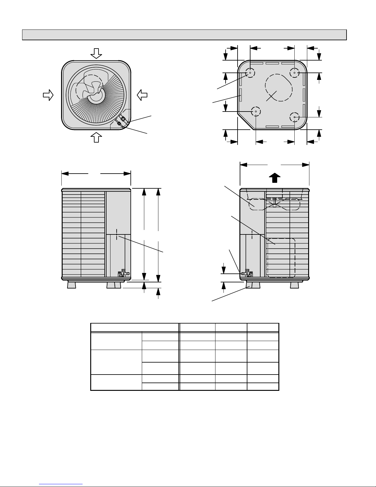
Unit Dimensions − inches (mm)
HSXA12-018
HSXA12-036
INLET
AIR
INLET AIR
INLET AIR
Top View
C
INLET
AIR
LIQUID LINE
CONNECTION
OPTIONAL UNIT
STAND-OFF KIT (4)
(Field Installed)
COIL DRAIN OUTLETS
(Around perimeter of base)
VAPOR LINE
CONNECTION
4-3/8
(111 )
6-3/8
(162)
OUTDOOR
COIL FAN
COMPRESSOR
4-3/8
(111 )
COMPRESSOR
6-3/8
(162)
Top View Base Section
C
DISCHARGE AIR
4-3/8
(111 )
4-3/8
(111 )
4-3/8
(111 )
4-3/8
(111 )
Side View
HSXA12-018
HSXA12-024
HSXA12-030
HSXA12-036
HSXA12-042
HSXA12-048
HSXA12-060
B
A
ELECTRICAL
INLETS
VAPOR &
LIQUID LINE
CONNECTION
2-3/4 (70)
2 (51)
3/4
(19)
OPTIONAL UNIT
STAND-OFF KIT (4)
(Field Installed)
Model No. A B C
in. 25 24-1/4 24-1/4
mm 635 616 616
in. 33 32-1/4 24-1/4
mm 838 819 616
in. 29 28−1/4 28−1/4
mm 737 718 718
Side View
Page 2
Setting the Unit
CAUTION
In order to avoid injury, take proper precaution when
lifting heavy objects.
CAUTION
Sharp sheet metal edges can cause injury. When
installing the unit, avoid accidental contact with
sharp edges.
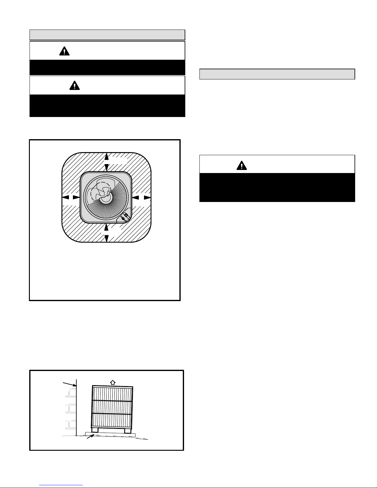
Refer to unit dimensions for sizing mounting slab, platforms or supports. Refer to figure 1 for installation clearances.
Installation Clearances
36
(914 mm)
36
(914 mm)
36*
(914 mm)
*NOTE − A service clearance of 30" (762 mm) must be maintained on one of the sides adjacent to the control box. Clearance to one of the other three sides must be 36" (914 mm).
Clearance to one of the remaining two sides may be 12" (304
mm) and the final side may be 6" (152 mm).
NOTE − A clearance of 24" (610 mm) must be maintained
between two units.
NOTE − 48" (1219 mm) clearance required on top
of unit. Maximum soffit overhang is 36" (914 mm).
Figure 1
Slab Mounting
When installing a unit at grade level, the top of the slab
should be high enough above the grade so that water from
higher ground will not collect around the unit. See figure 2.
Slab should have a slope tolerance away from the building
of 2 degrees or 2 inches per 5 feet (51 mm per 1524 mm).
Refer to roof mounting section for barrier construction if
unit must face prevailing winter winds.
Slab Mounting At Ground Level
structure
discharge air
36*
(914 mm)
Roof Mounting
Install unit at a minimum of 4 inches above the surface of
the roof. Care must be taken to ensure weight of unit is
properly distributed over roof joists and rafters. Either redwood or steel supports are recommended.
Electrical
In the U.S.A., wiring must conform with current local codes
and the current National Electric Code (NEC). In Canada,
wiring must conform with current local codes and the current
Canadian Electrical Code (CEC).
Refer to the furnace or blower coil installation instructions
for additional wiring application diagrams and refer to unit
nameplate for minimum circuit ampacity and maximum
overcurrent protection size.
WARNING
Unit must be grounded in accordance with national
and local codes.
ELECTRIC SHOCK HAZARD.
Can cause injury or death.
1 − Install line voltage power supply to unit from a properly
sized disconnect switch.
2 − Ground unit at unit disconnect switch or to an earth
ground.
NOTE − To facilitate conduit, a hole is in the bottom of
the control box. Connect conduit to the control box us
ing a proper conduit fitting.
NOTE − Units are approved for use only with copper
conductors.
24V, Class II circuit connections are made in the low
voltage junction box. Refer to figure 4 for field wiring
diagram.
NOTE − A complete unit wiring diagram is located in
side the unit control box cover.
3 − Install room thermostat (ordered separately) on an in-
side wall approximately in the center of the conditioned
area and 5 feet (1.5 m) from the floor. It should not be
installed on an outside wall or where it can be effected
by sunlight, drafts or vibrations.
4 − Install low voltage wiring from outdoor to indoor unit
and from thermostat to indoor unit. See figure 3.
Mounting slab must slope
away from building.
Figure 2
ground level
Page 3

Thermostat Designations
Thermostat Indoor Unit
R
W1
power
heat
R
W
NOTE − see unit wiring diagram for
power supply connections.
Outdoor Unit
Y
G
C
NOTE − If the indoor unit is not equipped with blower relay. It must be field−provided and installed (P−8−3251 or equivalent).
cooling
indoor blower
common
Y
G
C
Y1 Outdoor Unit
C Outdoor Unit
Figure 3
Typical Field Wiring Diagram
*
*
*
*May be optional
Figure 4
Page 4

Refrigerant Piping
If the HSXA12 unit is being installed with an indoor coil and
line set, make the refrigerant connections as outlined in this
section. If an existing line set and/or indoor coil is going to
be used to complete the HSXA12 system, refer to this section, as well as the flushing section which follows.
Field refrigerant piping consists of liquid and vapor lines
from the outdoor unit (sweat connections) to the indoor coil
(flare or sweat connections). Use Lennox L15 (sweat, nonflare) series line sets as shown in table 1 or use field-fabricated refrigerant lines. Refer to Refrigerant Piping Guide
(Corp. 9351−L9) for proper size, type, and application of
field−fabricated lines. Valve sizes are also listed in table 1.
Refrigerant Line Connections
HSXA12 Matched with New Indoor Coil and Line Set
If the HSXA12 is being used with an existing indoor coil
which was equipped with a liquid line which served as
a metering device (RFCI), the liquid line must be replaced prior to the installation of the HSXA12 unit.
If refrigerant lines are routed through a wall, seal and isolate
the opening so vibration is not transmitted to the building.
Table 1
Refrigerant Line Sets
Model
Valve Field Size
Connections
Liquid
Line
Vapor
Line
Recommended Line Set
Liquid
Line
Vapor
Line
L15
Line Sets
Installing Refrigerant Line
During the installation of any heat pump or a/c system, it is
important to properly isolate the refrigerant lines to prevent
unnecessary vibration. Line set contact with the structure
(wall, ceiling or floor) causes some objectionable noise
when vibration is translated into sound. As a result, more
energy or vibration can be expected. Closer attention to
line set isolation must be observed.
Following are some points to consider when placing and
installing a high−efficiency outdoor unit:
1- Placement − Be aware some localities are adopting
sound ordinances based on how noisy the unit is from
the adjacent property not at the original installation.
Install the unit as far as possible from the property line.
When possible, do not install the unit directly outside a
window. Glass has a very high level of sound transmission.
2- Line Set Isolation − The following illustrations demon-
strate procedures which ensure proper refrigerant line
set isolation. Figure 5 shows how to install line sets on
vertical runs. Figure 6 shows how to install line sets on
horizontal runs. Figure 7 shows how to make a transition
from horizontal to vertical. Finally, figure 8 shows how to
place the outdoor unit and line set.
L15−26
15 ft. − 50 ft.
(4.6 m − 15 m)
L15−41
15 ft. − 50 ft.
(4.6 m − 15 m)
L15−65
15 ft. − 50 ft.
(4.6 m − 15 m)
Field
Fabricated
−018
024
−030
−036
−042
−048
−060
3/8 in.
(10 mm)
3/8 in.
(10 mm)
3/8 in.
(10 mm)
3/8 in.
(10 mm)
5/8 in.
(16 mm)
3/4 in.
(19 mm)
7/8 in.
(22 mm)
1−1/8 in.
(29 mm)
3/8 in.
(10 mm)
3/8 in.
(10 mm)
3/8 in.
(10 mm)
3/8 in.
(10 mm)
5/8 in.
(19 mm)
3/4 in.
(19 mm)
7/8 in.
(22 mm)
1−1/8 in.
(29 mm)
NOTE − Units are designed for line sets of up to fifty feet (15
m). For applications longer than fifty feet, consult the Lennox Refrigerant Piping Guide (Corp. 9351−L9). Select line
set diameters from table 1 to ensure that oil returns to the
compressor.
Page 5
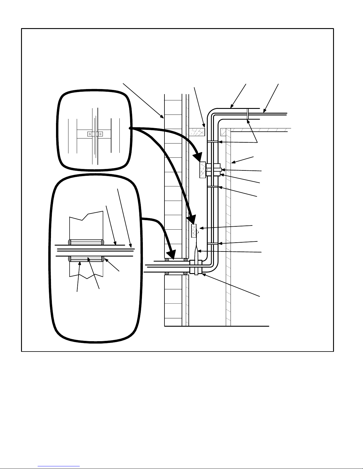
Refrigerant Line Sets
How To Install Vertical Runs
(new construction shown)
NOTE - Similar installation practices should be used if
line set is to be installed on exterior of outside wall.
Outside Wall
Wood Block
Between Studs
Liquid Line
Vapor Line
(wrapped with Armaflex)
Outside Wall
IMPORTANT - Refrigerant
lines must not contact wall.
Liquid LineVapor Line
Wire Tie
Inside Wall
Strap
Sleeve
Wire Tie
Wood Block
Wire Tie
Caulk
PVC Pipe
Fiberglass
Insulation
IMPORTANT - Refrigerant
lines must not contact
structure.
Strap
Sleeve
Figure 5
Page 6
 Loading...