

Lennox HS29-261, HS29-411, HS29-141, HS29-311, HS29-413 Unit Information
...
Service Literature
HS29 SERIES UNITS
The HS29 is a residential split-system condensing unit.
Condensing coil size, circuiting and air volume result in a
minimum SEER rating of 10.0. The series is designed for
use with an expansion valve or RFCIV system in the indoor unit. However, the HS29−651 and −060 use only the
TXV system.
The HS29−141 and −012 utilizes a rotary compressor. Other
HS29 units (−018, −024−2 and −211 through −653) utilize a reciprocating compressor. All compressors are hermetically sealed
for trouble-free operation and long service life. Compressor
components are spring-mounted within the sealed housing.
The compressor is installed in the unit on resilient rubber
mounts to assure quiet, vibration-free operation. A built-in
protection device assures protection from excessive
current and temperatures.
HS29−460 through HS29−650 models are furnished with
crankcase heaters to assure proper compressor lubrication at all times. The heater is temperature-actuated and
operates only when required. HS29−024−3 and HS29−030
through −060 units utilize a scroll compressor. The scroll operates like a standard compressor but it is unique in the way it
compresses refrigerant.
Several models are available in sizes ranging from 1 through 5
tons.
HS29
Corp. 9802−L3
Revised 04−2004
This manual is divided into sections which discuss the
major components, refrigerant system, charging procedure, maintenance and operation sequence.
All specifications in this manual are subject to change.
WARNING
Refrigerant can be harmful if it is inhaled. Refrigerant
must be used and recovered responsibly.
Failure to follow this warning may result in personal
injury or death.
IMPORTANT
Improper installation, adjustment, alteration, service
or maintenance can cause property damage, personal injury or loss of life. Installation and service must
be performed by a qualified installer or service
agency.
TABLE OF CONTENTS
Specifications 2. . . . . . . . . . . . . . . . . . . . . . . . . . . . . . . . .
Electrical Data 3. . . . . . . . . . . . . . . . . . . . . . . . . . . . . . . . .
I Unit Information 5. . . . . . . . . . . . . . . . . . . . . . . . . . . . . .
II Unit Components 5. . . . . . . . . . . . . . . . . . . . . . . . . . . . .
III Refrigerant System 8. . . . . . . . . . . . . . . . . . . . . . . . . .
IV Charging 11. . . . . . . . . . . . . . . . . . . . . . . . . . . . . . . . . . .
V Maintenance 13. . . . . . . . . . . . . . . . . . . . . . . . . . . . . . . .
VI Wiring Diagrams and Operation Sequence 15. . . . . .
Page 1
©1998 Lennox Industries Inc.
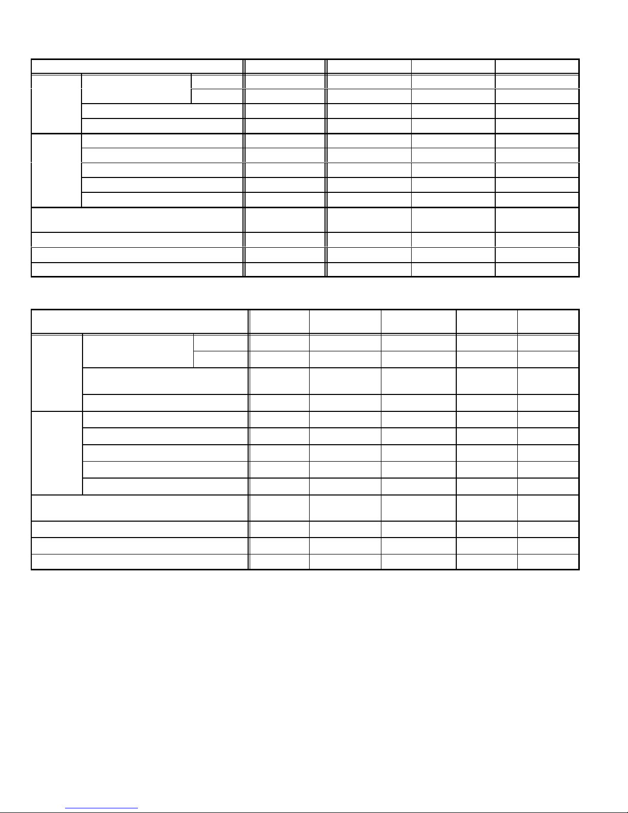
SPECIFICATIONS
Condenser
Fan
Fan
Model No. HS29-141 HS29-211 HS29-261 HS29-311
Condenser
Net face area - sq. ft. (m2)
Coil
Tube diameter in. (mm) & no. of rows 5/16 (7.9) 1 5/16 (7.9) 1 5/16 (7.9) 1 5/16 (7.9) 1
Fins per inch (m) 22 (866) 22 (866) 22 (866) 22 (866)
Diameter in. (mm) & no. of blades 18 (457) 3 18 (457) 3 18 (457) 3 18 (457) 3
Motor hp (W) 1/6 (124) 1/6 (124) 1/6 (124) 1/6 (124)
Condenser
Cfm (L/s) 2400 (1135) 2400 (1135) 2400 (1135) 2460 (1160)
Rpm 1105 1105 1105 1125
Watts 180 180 180 170
*Refrigerant charge furnished (HCFC-22)
Liquid line in. (mm) o.d. connection (sweat) 3/8 (9.5) 3/8 (9.5) 3/8 (9.5) 3/8 (9.5)
Suction line in. (mm) o.d. connection (sweat) 5/8 (15.9) 5/8 (15.9) 5/8 (15.9) 3/4 (19.1)
Shipping weight lbs. (kg) 1 package 146 (66) 146 (66) 148 (67) 157 (71)
*Refrigerant charge sufficient for 20 ft. (6.1 m) length of refrigerant lines.
3/8x5/16 in. (9.5x7.9mm) adaptor furnished for liquid line connection.
Model No.
Net face area - sq. ft. (m2)
Condenser
Coil
Tube diameter in. (mm) & no. of rows
Outer coil 7.56 (0.70) 11.33 (1.05) 11.33 (1.05) 13.22 (1.23)
Inner coil - - - - - - - - - - - - - - - -
2 lbs. 12 oz.
(1.25 kg)
3 lbs. 10 oz.
(1.64 kg))
3 lbs. 13 oz.
(1.73 kg))
4 lbs. 5 oz. (1.96 kg)
SPECIFICATIONS (contd.)
HS29-411
HS29-413
Outer coil 15.11 (1.40) 15.11 (1.40) 15.11 (1.40) 15.21 (1.41) 21.11 (1.96)
Inner coil - - - - 5.40 (0.50) 5.44 (0.50) 14.0 (13.4) 20.3 (1.89)
5/16 (7.9)
1
HS29-461
HS29-463
HS29-511
HS29-513
HS29-651
HS29-653
HS29-681
HS29-683
5/16 (7.9) 1.37 5/16 (7.9) 1.37 5/16 (7.9) 2 5/16 (7.9) 2
Fins per inch (m) 22 (866) 22 (866) 22 (866) 22 (866) 22 (866)
Diameter in. (mm) & no. of blades 18 (457) 4 18 (457) 4 18 (457) 4 18 (457) 4 18 (457) 4
Motor hp (W) 1/6 (124) 1/6 (124) 1/3 (249) 1/3 (249) 1/3 (249)
Condenser
Fan
Cfm (L/s) 2520 (1190) 2500 (1180) 2950 (1390) 2930 (1385) 2930 (1385)
Rpm 1100 1100 1100 1100 1100
Watts 200 200 310 310 310
*Refrigerant charge furnished (HCFC-22)
5 lbs. 0 oz.
(2.26 kg)
5 lbs. 9 oz. (2.52
kg)
6 lbs. 3 oz.
(2.81 kg)
7 lbs. 10 oz.
(3.46 kg)
12 lbs. 0 oz.
(5.44 kg)
Liquid line in. (mm) o.d. connection (sweat) 3/8 (9.5) 3/8 (9.5) 3/8 (9.5) 3/8 (9.5) 3/8 (9.5)
Suction line in. (mm) o.d. connection (sweat) 3/4 (19.1) 7/8 (22.2) 7/8 (22.2) 1-1/8 (28.6) 1-1/8 (28.6)
Shipping weight lbs. (kg) 1 package 165 (75) 191 (87) 196 (89) 212 (96) 254 (115)
*Refrigerant charge sufficient for 20 ft. (6.0 m) length of refrigerant lines.
Page 2
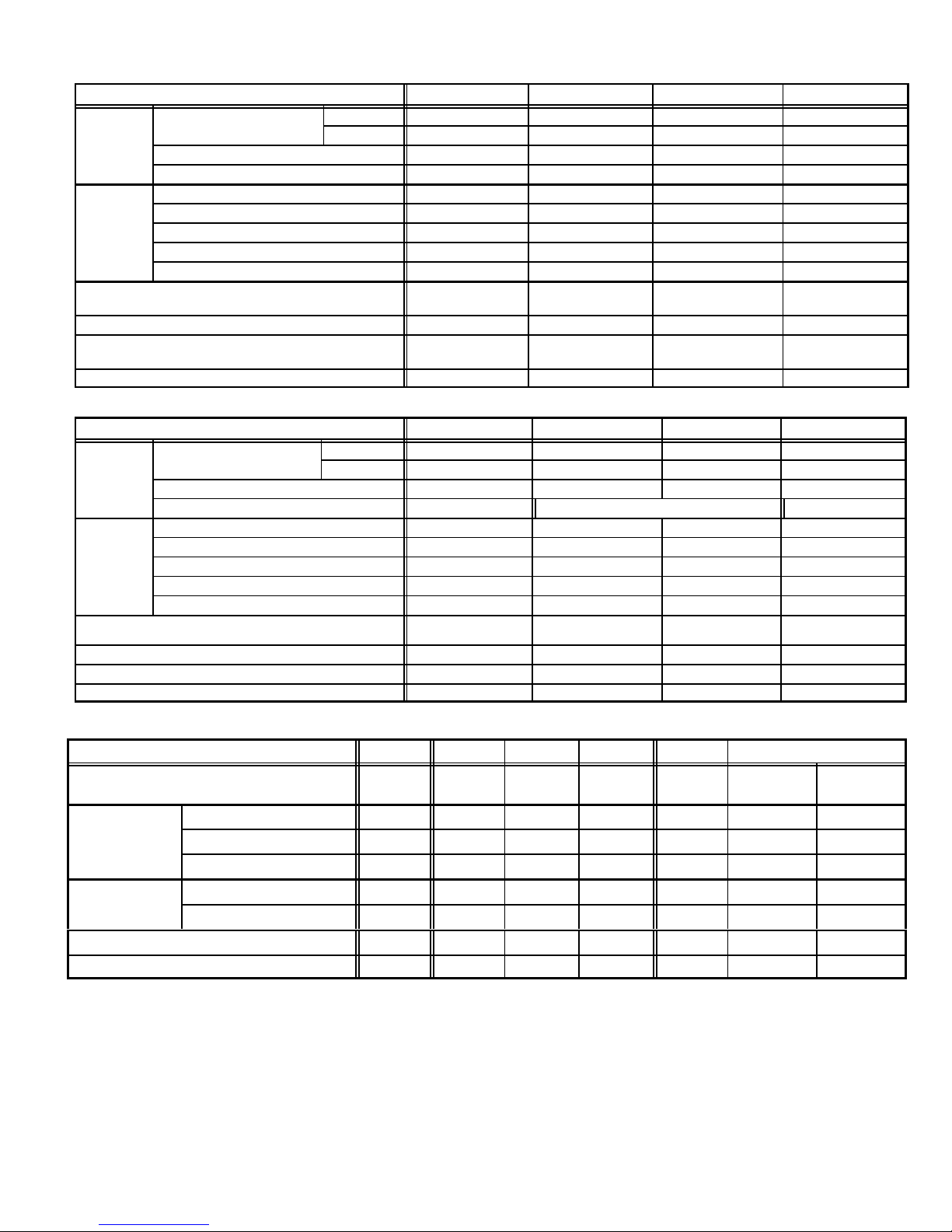
SPECIFICATIONS (contd.)
Condenser
Fan
Condenser
Fan
Condenser Coil
Model No. HS29-012 HS29-018 HS29-024 HS29-030
Outer coil 7.56 (0.70) 11.33 (1.05) 11.33 (1.05) 13.22 (1.23)
Inner coil - - - - - - - - - - - - - - - -
Condenser
Coil
Net face area - sq. ft. (m2)
Tube diameter in. (mm) & no. of rows 5/16 (7.9) 1 5/16 (7.9) 1 5/16 (7.9) 1 5/16 (7.9) 1
Fins per inch (m) 22 (866) 22 (866) 22 (866) 18 (748)
Diameter in. (mm) & no. of blades 18 (457) 3 18 (457) 3 18 (457) 3 18 (457) 3
Motor hp (W) 1/6 (124) 1/6 (124) 1/6 (124) 1/6 (124)
Condenser
Cfm (L/s) 2400 (1135) 2400 (1135) 2400 (1135) 2545 (1201)
Rpm 1105 1105 1105 1110
Watts 180 180 180 195
*Refrigerant charge furnished (HCFC-22)
3 lbs. 1 oz.
(1.38 kg)
3 lbs. 7 oz.
(1.55 kg)
3 lbs. 10 oz.
(1.64 kg)
4 lbs. 1 oz.
(1.83 kg)
Liquid line in. (mm) o.d. connection (sweat) 3/8 (9.5) 3/8 (9.5) 3/8 (9.5) 3/8 (9.5)
Suction line in. (mm) o.d. connection (sweat) 5/8 (15.9) 5/8 (15.9)
5/8 (15.9) −1, −2 units
3/4 (19) −3 units
3/4 (19.1)
Shipping weight lbs. (kg) 1 package 146 (66) 146 (66) 148 (67) 140 (64)
*Refrigerant charge sufficient for 15 ft. (4.5 m) length of refrigerant lines. 3/8 x 5/16 in. (9.5 x 7.9 mm) adaptor furnished for liquid line connection.
SPECIFICATIONS (contd.)
Model No. HS29-036 HS29-042 HS29-048 HS29-060
Outer coil 15.11 (1.40) 15.11 (1.40) 15.11 (1.40) 15.11 (1.40)
Inner coil - - - - 5.40 (0.50) 5.40 (0.50) 14.40 (1.34)
Condenser
Coil
Net face area - sq. ft. (m2)
Tube diameter in. (mm) & no. of rows 5/16 (7.9) 1 5/16 (7.9) 1.37 5/16 (7.9) 1.37 5/16 (7.9) 2
Fins per inch (m) 22 (866) 18 (748) 18 (748)
Diameter in. (mm) & no. of blades 18 (457) 4 18 (457) 4 18 (457) 4 18 (457) 4
Motor hp (W) 1/6 (124) 1/6 (124) 1/3 (249) 1/3 (249)
Condenser
Cfm (L/s) 2520 (1190) 2610 (1232) 3115 (1470) 3010 (1420)
Rpm 1100 1105 1125 1125
Watts 200 200 325 315
*Refrigerant charge furnished (HCFC-22)
1 ph−4 lbs. 6 oz. (1.98 kg)
3 ph−4 lbs 13 oz. (2.17 kg)
1 ph−5 lbs. 7 oz. (2.45 kg)
3 ph−5 lbs 6 oz. (2.43
1ph 5 lbs. 8 oz. (2.48 kg)
3ph 6 lbs 0 oz. (2.72)
1 ph 8 lbs. 0 oz. (3.62 kg)
3 ph 7 lbs 7 oz. (3.36)
Liquid line in. (mm) o.d. connection (sweat) 3/8 (9.5) 3/8 (9.5) 3/8 (9.5) 3/8 (9.5)
Suction line in. (mm) o.d. connection (sweat) 3/4 (19.1) 7/8 (22.2) 7/8 (22.2) 1-1/8 (28.6)
Shipping weight lbs. (kg) 1 package 145 (66) 158 (72) 191 (87) 207 (94)
*Refrigerant charge sufficient for 15 ft. (4.5 m) length of refrigerant lines.
ELECTRICAL DATA
Model No. HS29-141 HS29-211 HS29-261 HS29-311 HS29-411 HS29-413
Line voltage data 60 hz
208/230v
1ph
208/230v
1ph
Rated load amps 4.9 8.6 10.1 11.8 17.5 10.3 4.3
Compressor Power factor .97 .97 .96 .92 .90 .83 .83
Locked rotor amps 26.3 48.3 60.0 69.4 96.0 75.0 40.0
Condenser Coil
Fan Motor
Full load amps 1.1 1.1 1.1 1.1 1.1 1.1 0.55
Locked rotor amps 1.9 1.9 1.9 1.9 1.9 1.9 1.0
Rec. maximum fuse or circuit breaker size (amps) 15 15 20 25 40 20 10
*Minimum circuit ampacity 7.3 11.0 13.8 15.9 23.8 14.0 6.5
*Refer to National or Canadian Electrical Code manual to determine wire, fuse and disconnect size requirements.
NOTE Extremes of operating range are plus 10% and minus 5% of line voltage.
208/230v
1ph
208/230v
1ph
208/230v
1ph
208/230v
3ph
460v
3ph
Page 3
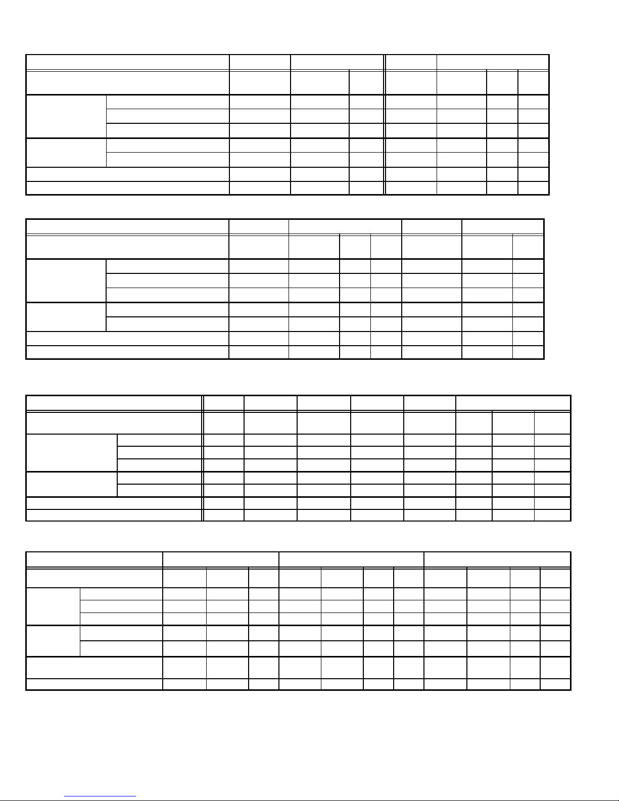
ELECTRICAL DATA
Condenser Coil
Condenser Coil
Condenser Coil
Model No. HS29-461 HS29-463 HS29-511 HS29-513
Line voltage data 60 hz
208/230v
1ph
208/230v
3ph
460v
3ph
208/230v
1ph
208/230v
3ph
460v
3ph
Rated load amps 17.5 12.8 6.4 23.4 14.0 7.1 5.8
Compressor Power factor .98 .93 .93 .98 .88 .88 .88
Locked rotor amps 92.0 87.0 44.0 110.0 91.0 46.0 37.0
Condenser Coil
Fan Motor
Full load amps 1.1 1.1 0.55 1.9 1.9 0.90 0.90
Locked rotor amps 1.9 1.9 1.0 4.1 4.1 2.1 2.1
Rec. maximum fuse or circuit breaker size (amps) 40 25 15 50 30 15 10
*Minimum circuit ampacity 23.0 17.1 8.6 31.2 19.4 9.8 8.2
*Refer to National or Canadian Electrical Code manual to determine wire, fuse and disconnect size requirements.
NOTE Extremes of operating range are plus 10% and minus 5% of line voltage.
ELECTRICAL DATA
Model No. HS29-651 HS29-653 HS29-681 HS29-683
Line voltage data 60 hz
208/230v
1ph
Rated load amps 26.9 17.3 9.0 7.1 27.1 18.6 7.9
Compressor Power factor .98 .86 .86 .86 .97 .86 .86
Locked rotor amps 123.0 128.0 64.0 51.0 175.0 128.0 63.0
Condenser Coil
Fan Motor
Full load amps 1.9 1.9 0.90 0.90 1.9 1.9 0.90
Locked rotor amps 4.1 4.1 2.1 2.1 4.1 2.1 2.1
Rec. maximum fuse or circuit breaker size (amps) 60 40 20 15 60 40 15
*Minimum circuit ampacity 35.5 23.5 12.2 9.8 35.8 24.2 10.8
*Refer to National or Canadian Electrical Code manual to determine wire, fuse and disconnect size requirements.
NOTE Extremes of operating range are plus 10% and minus 5% of line voltage.
208/230v
3ph
460v
3ph
575v
3ph
208/230v
1ph
208/230v
3ph
460v
575v
3ph
3ph
ELECTRICAL DATA
Model No. HS29-012 HS29-018 HS29-024−2 HS29-024−3 HS29-030 HS29-036
Line voltage data 60 hz 208/230v
1ph
Rated load amps 4.9 8.6 7.9 12.2 14.7 16.0 10.3 5.1
208/230v
1ph
208/230v
1ph
208/230v
1ph
208/230v
1ph
208/230
v
1ph
208/230v
3ph
460v
Compressor Power factor .97 .97 .97 .96 .90 .91 .83 .83
Locked rotor amps 26.3 48.3 48.3 61.0 84.0 100.0 77.0 39.0
Condenser Coil
Fan Motor
Full load amps 1.1 1.1 1.1 1.1 1.1 1.1 1.1 0.55
Locked rotor amps 1.9 1.9 1.9 1.9 1.9 1.9 1.9 1.0
Rec. maximum fuse or circuit breaker size (amps) 15 20 15 25 30 35 20 10
*Minimum circuit ampacity 7.3 11.9 11.0 16.4 19.5 21.1 14.0 6.9
*Refer to National or Canadian Electrical Code manual to determine wire, fuse and disconnect size requirements.
NOTE Extremes of operating range are plus 10% and minus 5% of line voltage.
ELECTRICAL DATA
Model No. HS29−042 HS29-048 HS29-060
Line voltage data 60 hz
208/230v
1ph
Rated load amps 20.3 12.4 6.4 23.7 12.8 6.4 5.1 28.8 15.4 7.6 5.9
Compressor Power factor .84 .93 .93 .98 .88 .88 .88 .95 0.86 0.86 0.86
Locked rotor amps 127.0 88.0 44.0 129.0 91.0 46.0 37.0 169.0 124.0 59.6 49.4
Condenser
Coil
Fan Motor
Rec. maximum fuse or circuit breaker
size (amps)
Full load amps 1.1 1.1 .55 1.9 1.9 0.9 0.9 1.9 1.9 0.90 0.90
Locked rotor amps 1.9 1.9 1.0 4.1 4.1 2.1 2.1 4.1 4.1 2.1 2.1
40 25 15 50 30 15 10 60 35 15 10
*Minimum circuit ampacity 26.4 16.6 8.6 31.5 17.9 8.9 7.3 37.9 21.2 10.4 8.3
*Refer to National or Canadian Electrical Code manual to determine wire, fuse and disconnect size requirements.
NOTE Extremes of operating range are plus 10% and minus 5% of line voltage.
208/230v
3ph
460v
3ph
208/230v
1ph
208/230v
3ph
460v
3ph
575v
3ph
208/230v
1ph
208/230v
3ph
460v
3ph
3ph
575v
3ph
Page 4
I − UNIT INFORMATION
HS29 condensing units are available in 1, 1 -1/2, 2, 2 -1/2, 3, 3
-1/2, 4 and 5 ton capacities.
All major components (indoor blower/coil) must be matched according to Lennox recommendations for the compressor to be
covered under warranty. Refer to the Engineering Handbook
for approved system matchups. A misapplied system will
cause erratic operation and can result in early compressor failure.
II − UNIT COMPONENTS
Unit components are illustrated in figure 3.
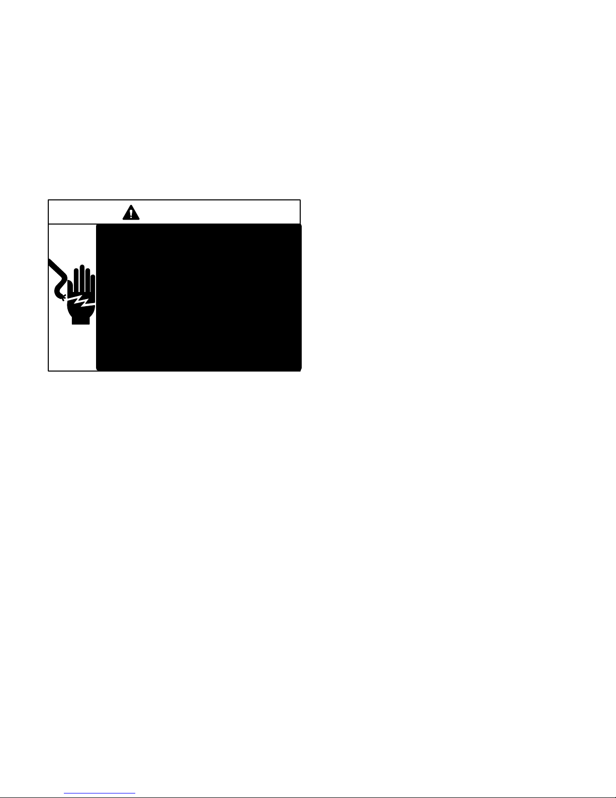
DANGER
Electric Shock Hazard.
May cause injury or death.
Disconnect all remote electrical power
supplies berore opening unit panel. Unit
may have multiple power supplies.
Some units are equipped with single−
pole contactors. When unit is equipped
with a single−pole contactor, line voltage
is present at all components (even when
unit is not in operation).
3 − Transformer T5
Transformer T5 is used on all J" voltage units. T5 is used as a
step-down transformer for the outdoor fan motor. The transformer is located inside the unit control box (see figure 1). The
transformer is rated at 3.4 VA with a 575 volt primary and a 460
volt secondary.
4 − Start Capacitor C7
All HS29−461, 511, 651, 012, 018 and 024−2 units use a
start capacitor (C7) wired in parallel with the compressor
side of the dual capacitor. The capacitor is located inside
the unit control box (see figure 1). C7 is switched off by
potential relay (K31) when the compressor nears full
speed. See side of capacitor for MFD ratings.
5 − Fan Capacitor C1
The fans in three-phase HS29−413, −463, −513, −653,
−683, −036, −042, −048 and −060 units use permanent split
capacitor motors. A single capacitor C1 is used for the
fan motor. The capacitor is located inside the unit control
box (see figure 1). See side of capacitor for MFD ratings.
6 − Potential (Start) Relay K31
A − Control Box (Figure 1 and Figure 2)
Electrical openings are provided under the control box cover. Field thermostat wiring is made to color-coded pigtail
connections.
1 − Compressor Contactor K1
The compressor is energized by a contactor located in the
control box. See figure 1 and figure 2. Single−pole and twopole contactors are used in single-phase units. See wiring
diagrms for specific unit. Three-pole contactors are used in
three-phase units. K1 is energized by the indoor thermostat terminal Y1 (24V) when thermostat demand is present.
HS29 units are not equipped with a 24V transformer. All
24 VAC controls are powered by the indoor unit. Refer to
wiring diagram.
2 − Dual Capacitor C12
The compressor (scroll, rotary or reciprocating) and fan
in single-phase units use permanent split capacitor motors. The capacitor is located inside the unit control box
(see figure 1 and figure 2). A single dual" capacitor
(C12) is used for both the fan motor and the compressor
(see unit wiring diagram). The fan side and the compressor side of the capacitor have different MFD ratings and
must be exact when replacing. See side of capacitor for
ratings.
All HS29−461, 511, 651, 012, 018 and 024−2 units use a
potential relay which controls the operation of the starting circuit. The potential relay is located inside the unit control box
(see figure 1). The relay is normally closed when contactor
K1 is de-energized. When K1 energizes, the compressor im-
mediately begins start-up. K31 remains closed during compressor start-up and the start capacitor C7 remains in the cir-
cuit. When the compressor reaches 75% of its speed, K31 is
energized. When K31 energizes, the contacts open and
the start capacitor C7 is taken out of the circuit.
B − Compressor
(Rotary, Reciprocating and Scroll)
HS29−141 and −012 units utilize a rotary compressor.
HS29−018,−024−2, and −211 through −653 units utilize a
conventional reciprocating compressor. See ELEC-
TRICAL DATA tables or compressor nameplate for compressor specifications.
HS29−024−3 and HS29−030 through −060 units utilize a scroll
compressor. The scroll compressor design is simple, efficient
and requires few moving parts. A cutaway diagram of the scroll
compressor is shown in figure 4. The scrolls are located in the
top of the compressor can and the motor is located just below.
The oil level is immediately below the motor.
Page 5
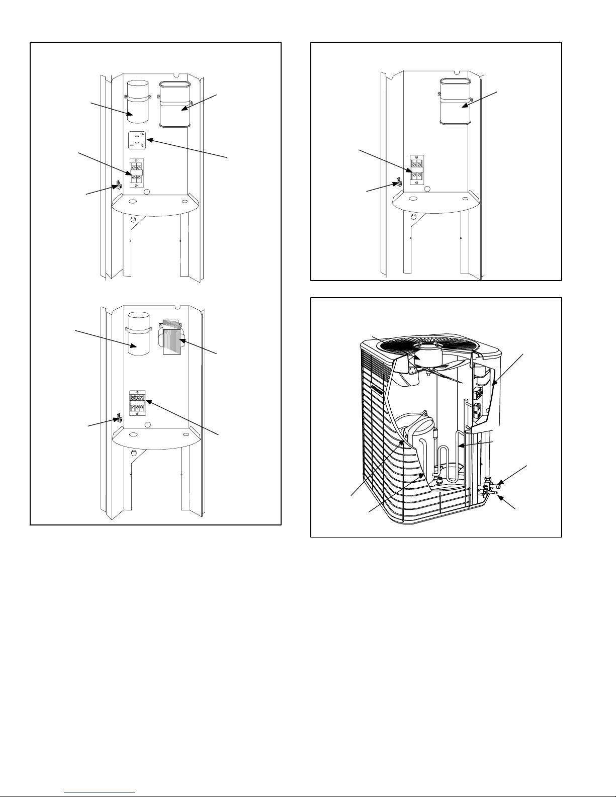
HS29 SINGLE-PHASE UNIT CONTROL BOX
WITH NON−SCROLL COMPRESSOR
HS29 SINGLE−PHASE UNIT CONTROL BOX
WITH SCROLL COMPRESSOR
START
CAPACITOR
(C7)
COMPRESSOR
CONTACTOR
(K1)
GROUNDING
LUG
DUAL CAPACITOR
RELAY (K31)
HS29 THREE-PHASE UNIT CONTROL BOX
FAN
CAPACITOR (C1)
TRANSFORMER
(T5) J" VOLT-
AGE UNITS ON LY
(C12)
POTENTIAL
COMPRESSOR
CONTACTOR
(K1)
GROUNDING
LUG
HS29 UNIT COMPONENTS
OUTDOOR
FAN/MOTOR
DUAL CAPACITOR
(C12)
FIGURE 2
CONTROL
BOX
GROUNDING
LUG
FIGURE 1
COMPRESSOR
CONTACTOR
(K1)
COMPRESSOR
SUCTION
LINE
FIGURE 3
DISCHARGE
LINE
SUCTION LINE
SERVICE VALVE
LIQUID LINE
SERVICE VALVE
Page 6
 Loading...