

Lennox HS27-024, HS27-042, HS27 Series, HS27-030, HS27-036 Installation Instructions Manual
INSTALLATION
2000 Lennox Industries Inc.
Dallas, Texas, USA
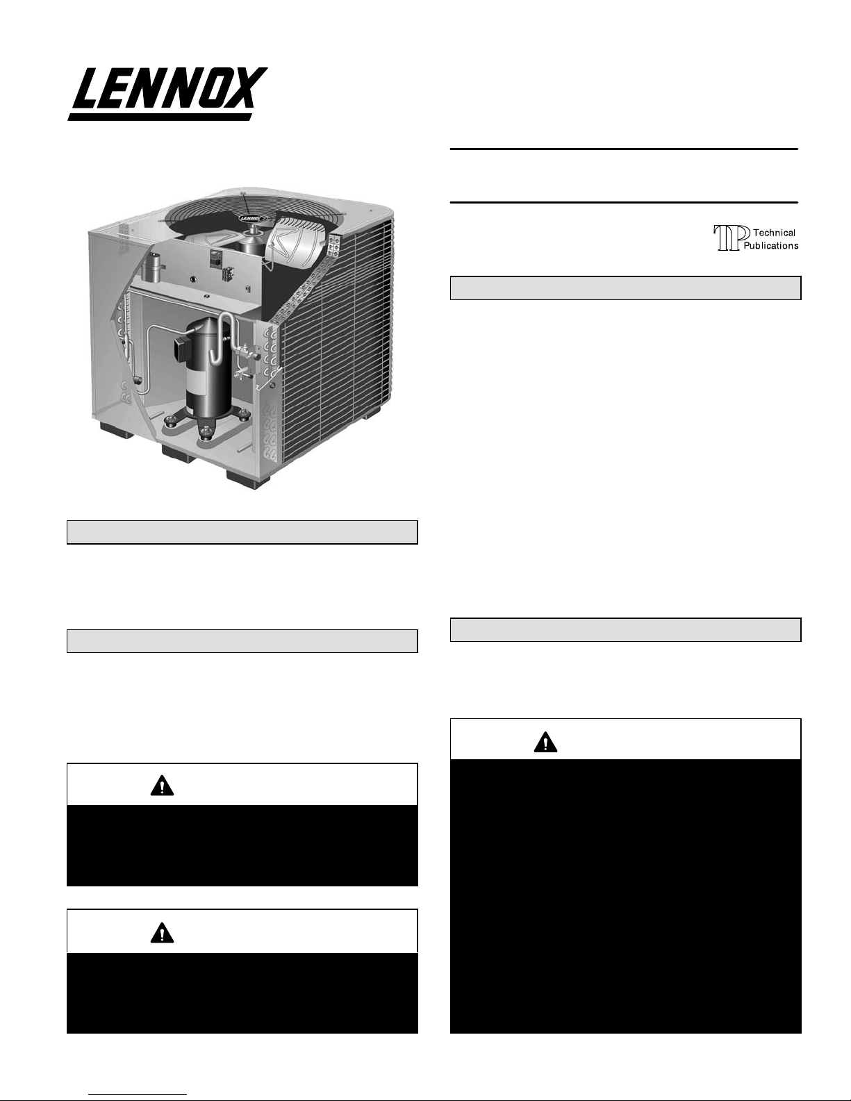
HS27 Outdoor Unit
HS27 outdoor units are designed for expansion valve systems only. They are not designed for RFC systems. Refer to
Lennox engineering handbook for expansion valve kits
which must be ordered separately.
Shipping & Packing List
1 − Assembled HS27 outdoor unit
2 − Grommets (for liquid and vapor lines)
1 − Bushing (for low voltage wiring)
Check equipment for shipping damage. If you find any
damage, immediately contact the last carrier.
WARNING
Improper installation, adjustment, alteration, service
or maintenance can cause property damage, personal injury or loss of life. Installation and service must
be performed by a qualified installer or service
agency.
IMPORTANT
The Clean Air Act of 1990 bans the intentional venting of refrigerant (CFC’s and HCFC’s) as of July 1,
1992. Approved methods of recovery, recycling or
reclaiming must be followed. Fines and/or incarceration may be levied for noncompliance.
INSTRUCTIONS
HS27 SERIES UNITS
CONDENSING UNITS
504,669M
02/04
Supersedes 12/02
Table of Contents
HS27 Outdoor Unit 1. . . . . . . . . . . . . . . . . . . . . . . . . . . . .
Shipping & Packing List 1. . . . . . . . . . . . . . . . . . . . . . . . .
General Information 1. . . . . . . . . . . . . . . . . . . . . . . . . . . . .
Unit Dimensions 2. . . . . . . . . . . . . . . . . . . . . . . . . . . . . . . .
Parts Arrangement 3. . . . . . . . . . . . . . . . . . . . . . . . . . . . .
Setting the Unit 3. . . . . . . . . . . . . . . . . . . . . . . . . . . . . . . . .
Electrical 3. . . . . . . . . . . . . . . . . . . . . . . . . . . . . . . . . . . . . .
Refrigerant Piping 5. . . . . . . . . . . . . . . . . . . . . . . . . . . . . .
Refrigerant Metering Device 9. . . . . . . . . . . . . . . . . . . . .
Manifold Gauge Set 9. . . . . . . . . . . . . . . . . . . . . . . . . . . . .
Service Valves 9. . . . . . . . . . . . . . . . . . . . . . . . . . . . . . . . .
Leak Testing 10. . . . . . . . . . . . . . . . . . . . . . . . . . . . . . . . . .
Evacuation 11. . . . . . . . . . . . . . . . . . . . . . . . . . . . . . . . . . .
Start−Up 12. . . . . . . . . . . . . . . . . . . . . . . . . . . . . . . . . . . . . .
Charging 12. . . . . . . . . . . . . . . . . . . . . . . . . . . . . . . . . . . . .
System Operation 14. . . . . . . . . . . . . . . . . . . . . . . . . . . . .
Maintenance 14. . . . . . . . . . . . . . . . . . . . . . . . . . . . . . . . . .
Optional Accessories 14. . . . . . . . . . . . . . . . . . . . . . . . . .
Start−up & Performance Check List 15. . . . . . . . . . . . . . .
RETAIN THESE INSTRUCTIONS
FOR FUTURE REFERENCE
General Information
These instructions are intended as a general guide and do
not supersede local codes in any way. Consult authorities
having jurisdiction before installation.
WARNING
This product and/or the indoor unit it is matched with
may contain fiberglass wool.
Disturbing the insulation during installation, maintenance, or repair will expose you to fiberglass wool
dust. Breathing this may cause lung cancer. (Fiberglass wool is known to the State of California to
cause cancer.)
Fiberglass wool may also cause respiratory, skin,
and eye irritation.
To reduce exposure to this substance or for further
information, consult material safety data sheets
available from address shown below, or contact your
supervisor.
Lennox Industries Inc.
P.O. Box 799900
Dallas, TX 75379−9900
Litho U.S.A.
02/04
*2P0204*
Page 1
504,669M
*P504669M*
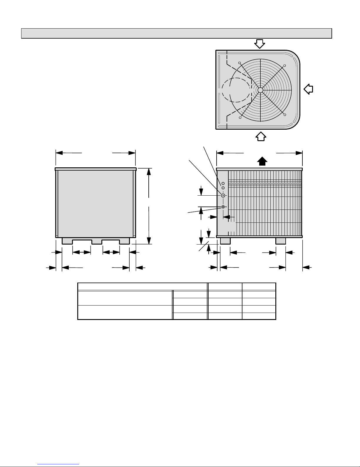
Unit Dimensions − inches (mm)
HS27-024
HS27-036
airinlet
inlet
COMPRESSOR
air
2
(51)
3-7/8
(98)
32-1/8 (816)
7-1/2
(191)
4-7/8 (22)
28-1/8 (714)
HS27-024
HS27-030
HS27-036
HS27-042
7-1/2
(191)
electrical
3-7/8
(98)
(51)
inlets
vapor line
inlet
A
liquid
line inlet
4-1/2 (114)
B
2-3/4 (70)
2
1-3/8
(35)
DISCHARGE AIR
2-9/16
(65)
4
(102)
Top View
34-1/16 (865)
18-5/8
(473)
26-5/8 (676)
Side ViewAccess View
Model No. A B
in. 30-7/8 12-3/4
mm 784 324
in. 40-7/8 19-3/4
mm 1038 502
airinlet
4
(102)
6-1/16
(154)
Page 2
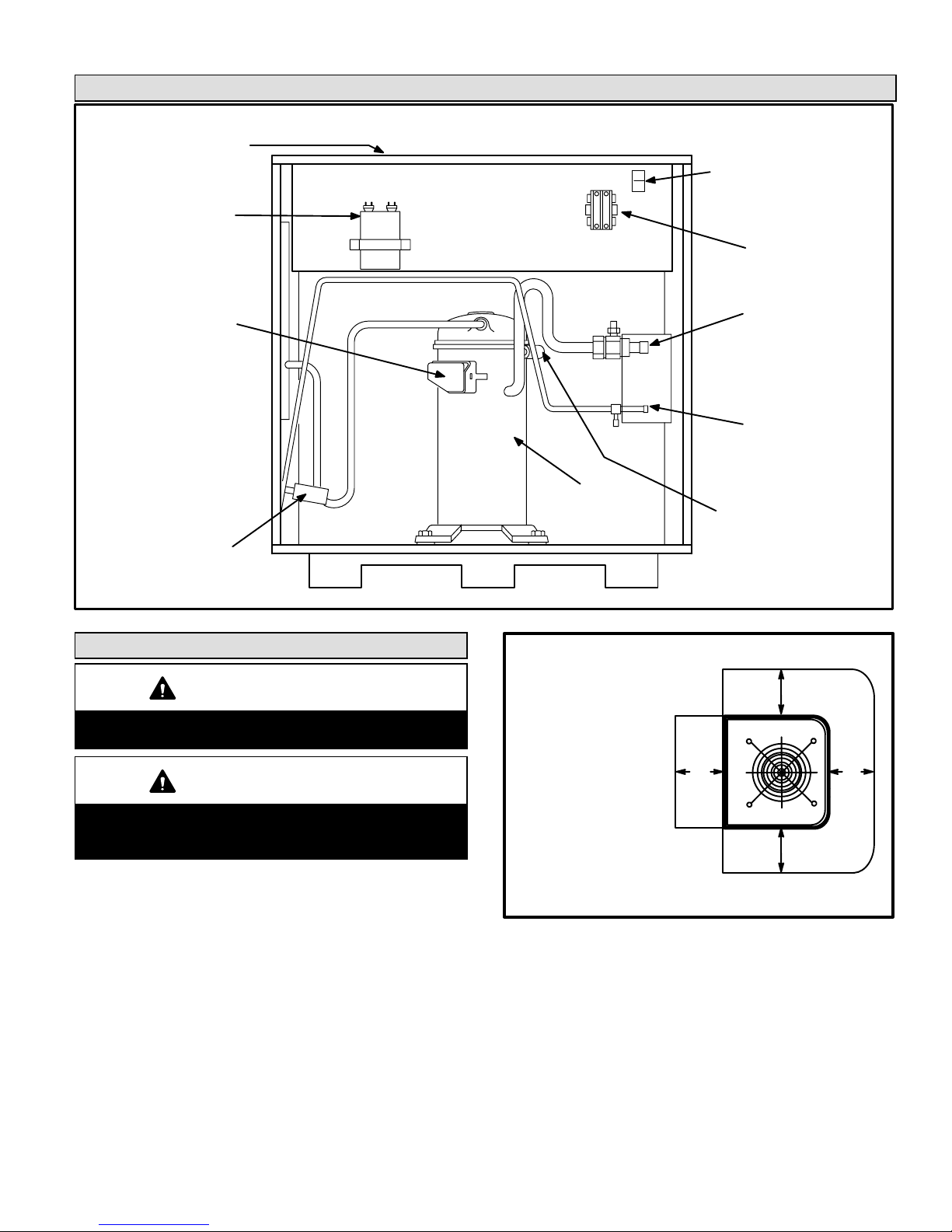
Parts Arrangement
outdoor fan
(not shown)
top of cabinet
run capacitor
ground lug
contactor
terminal box
high pressure
switch
Figure 1
Setting the Unit
CAUTION
In order to avoid injury, take proper precaution when
lifting heavy objects.
CAUTION
Danger of sharp metallic edges. Can cause injury.
Take care when servicing unit to avoid accidental
contact with sharp edges.
Refer to unit dimensions for sizing mounting slab, platforms, or supports. Refer to figure 2 for installation clearances.
vapor valve
and gauge port
liquid line
service valve
and gauge port
compressor
low pressure
switch
Installation Clearances
NOTE − A service access
clearance of 30" (762 mm)
must be maintained in front
of the service access panel.
Clearance to one side must
be 36" (914 mm). Clearance
to one of the remaining two
sides may be 12" (304 mm)
and the final side may be 6"
(152 mm).
NOTE − A clearance of 24" (610 mm)
must be maintained between two units.
NOTE − 48" (1219 mm) clearance required on top
of unit. Maximum soffit overhang is 36" (914 mm).
36"
(914 mm)
*36"
(914 mm)
*36"
(914 mm)
36"
(914 mm)
Figure 2
Page 3
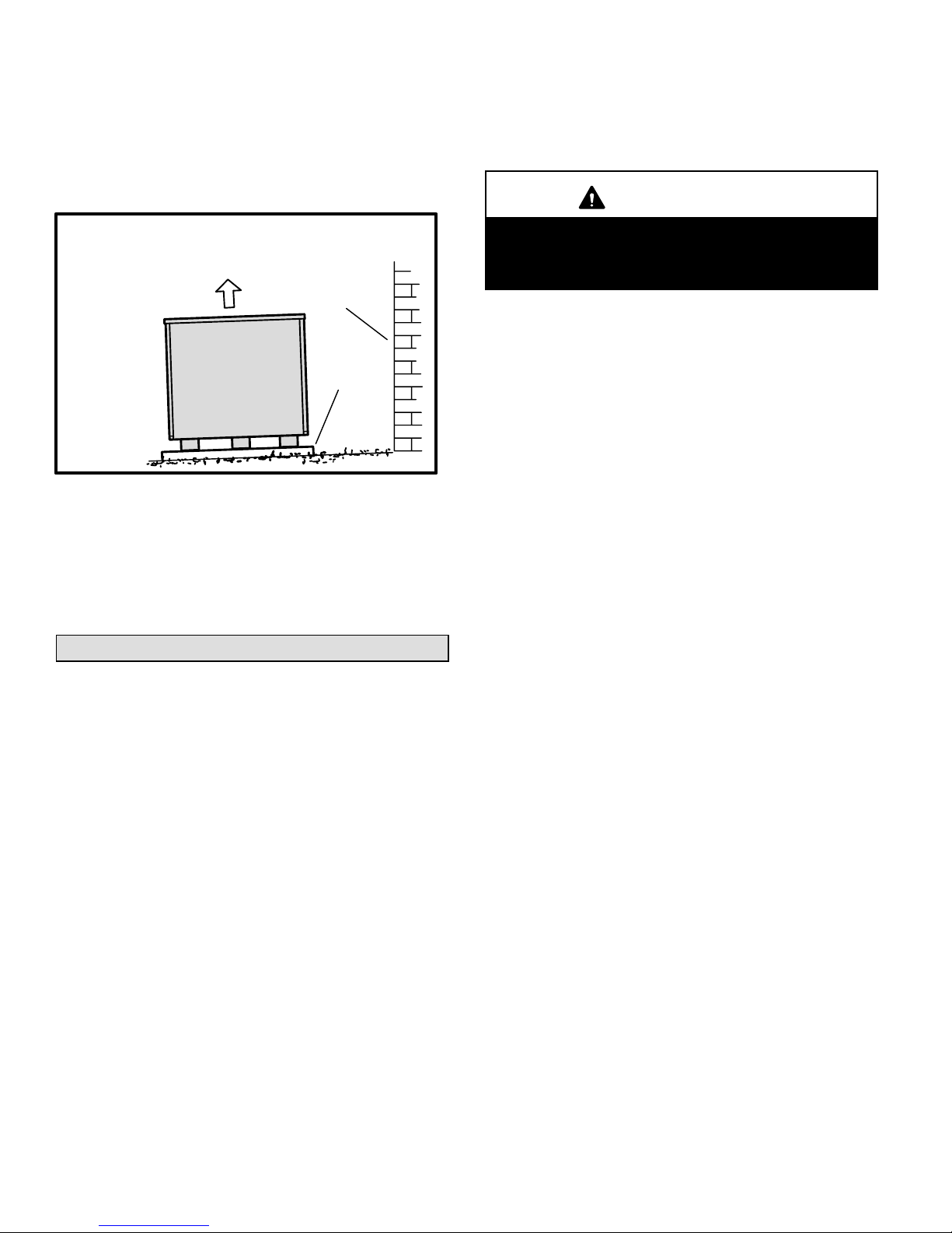
A − Slab Mounting
When you install the unit at grade level, the top of the slab
should be high enough above the grade so that water from
higher ground will not collect around the unit. See figure 3.
Slab should have a slope tolerance away from the building
of 2 degrees or 2 inches per 5 feet (51 mm per 1.5 m).
Refer to the furnace or blower coil installation instructions
for additional wiring application diagrams and refer to unit
nameplate for minimum circuit ampacity and maximum
overcurrent protection size.
WARNING
2 degrees or
2 in. per 5 foot
(51 mm per 1.5 m)
slope tolerance away
from building structure
ground level
Slab Mounting
discharge air
building
structure
mounting
slab
Figure 3
B − Roof Mounting
Install unit at a minimum of 4 inches above surface of the roof.
Care must be taken to ensure weight of unit is properly distributed over roof joists and rafters. Either redwood or steel supports are recommended.
Electrical
In the U.S.A., wiring must conform with current local codes
and the current National Electric Code (NEC). In Canada,
wiring must conform with current local codes and the current
Canadian Electrical Code (CEC).
Unit must be grounded in accordance with
national and local codes.
Electric Shock Hazard.
Can cause injury or death.
1. Install line voltage power supply to unit from a properly
sized disconnect switch.
2. Ground unit at unit disconnect switch or to an earth
ground.
NOTE − To facilitate conduit, a hole is in the bottom of
the control box. Connect conduit to the control box us
ing a proper conduit fitting.
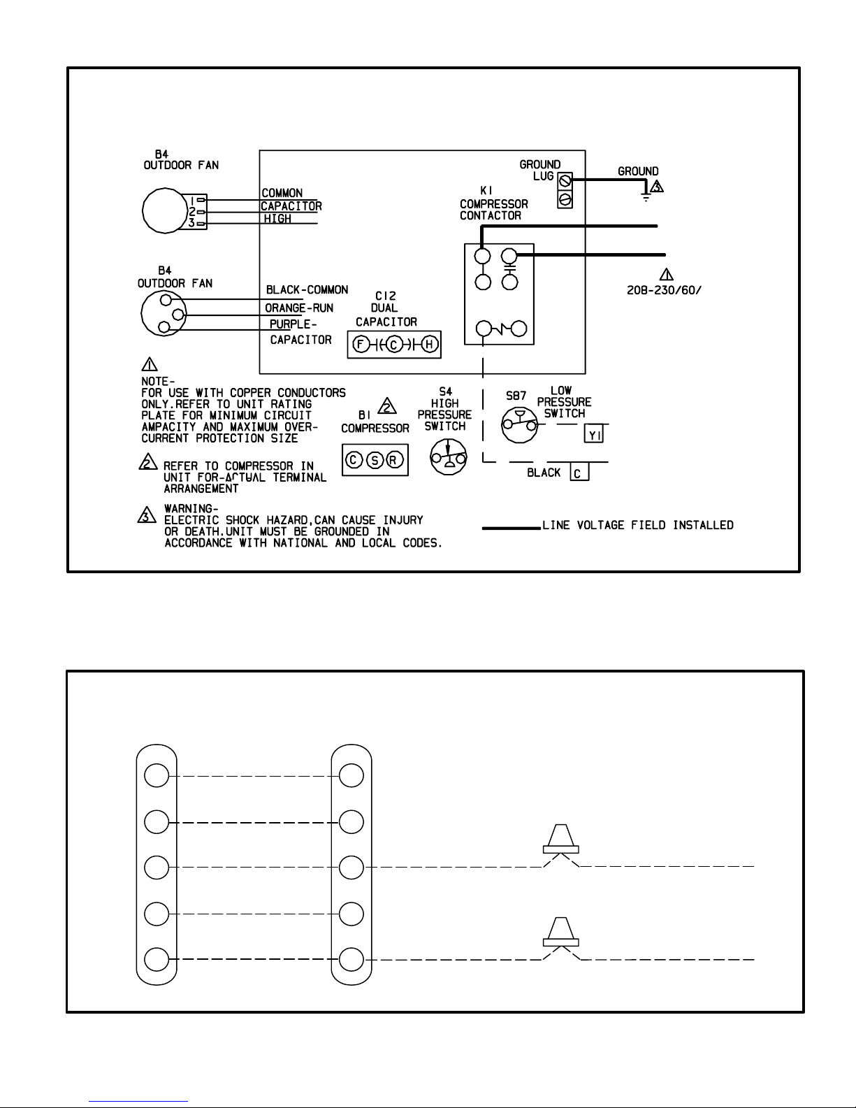
NOTE − Units are approved for use only with copper
conductors.
24V, Class II circuit connections are made in the low
voltage junction box. Refer to figure 4 for field wiring
diagram.
NOTE − A complete unit wiring diagram is located in
side the unit control box cover.
3. Install room thermostat (ordered separately) on an inside wall approximately in the center of the conditioned
area and 5 feet (1.5 m) from the floor. It should not be
installed on an outside wall or where it can be effected
by sunlight, drafts or vibrations.
4. Install low voltage wiring from outdoor to indoor unit
and from thermostat to indoor unit. See figure 5.
Page 4
(LEADLESS)
Outdoor Unit
Field Wiring Diagram
YELLOW
Thermostat Designations
Thermostat Furnace
R
W1
Y
G
C
power
heat
cooling
indoor blower
common
R
W
Y
G
C
Figure 4
NOTE − see unit wiring diagram for
power supply connections.
Outdoor Unit
Y1 Outdoor Unit
C Outdoor Unit
NOTE − If the indoor unit is not equipped with blower relay, it must be field−provided and installed (P−8−3251 or equivalent).
Figure 5
Page 5
 Loading...