

SERVICE
INFORMATION
Corp. 9622−L12
Revised 04−2002
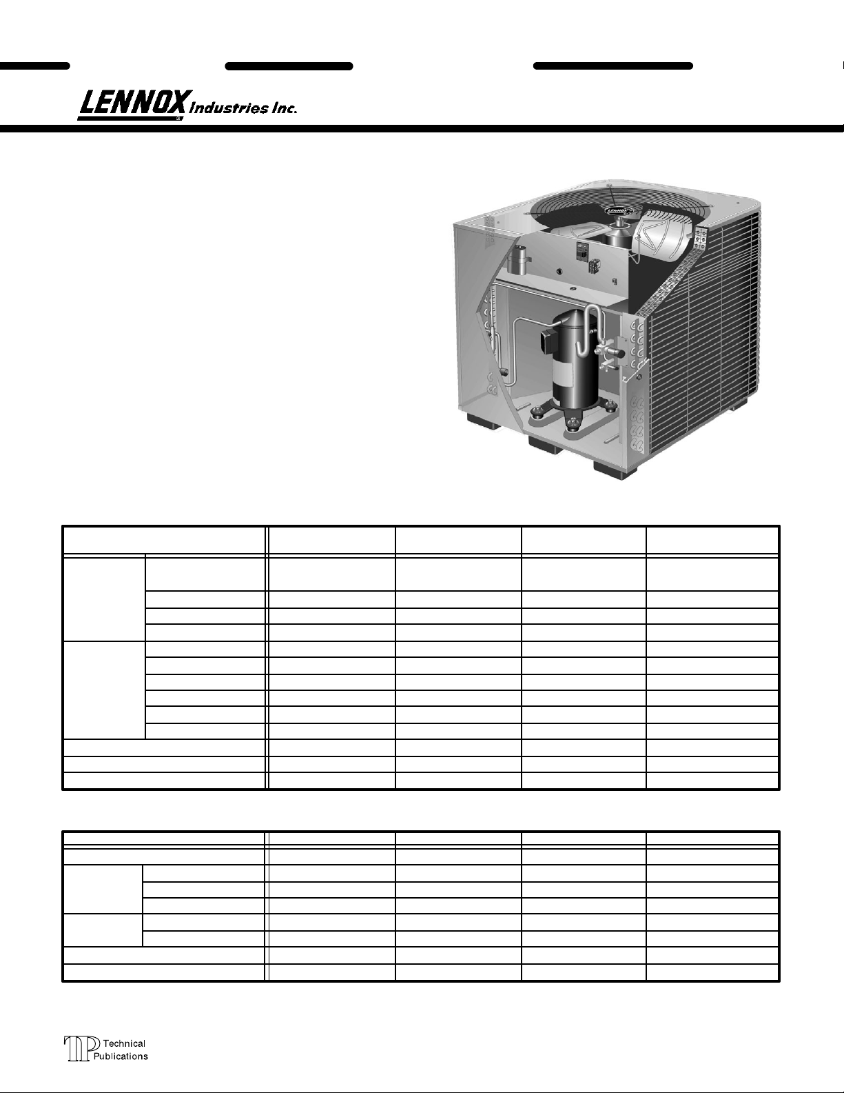
HS26 SERIES UNITS
The HS26 is a high efficiency residential split−system con
densing unit which features a scroll compressor. Early
model HS26 units (−261,−311,−411, and −461) are available
in sizes ranging from 2 through 3−1/2 tons. Late model
HS26 units (−018, −024, −030, −036, −042, −048 and −060)
are available in sizes ranging from 1−1/2 through 5 tons.
The series is designed for use with an expansion valve in
the indoor unit.This manual is divided into sections which
discuss the major components, refrigerant system, charg
ing procedure, maintenance and operation sequence. In
formation in this manual covers both early and late model
HS26 units.
All specifications in this manual are subject to change.
UNIT
HS26
EARLY/LATE
MODEL SERIES
Litho U.S.A.
Late Model
HS26 shown
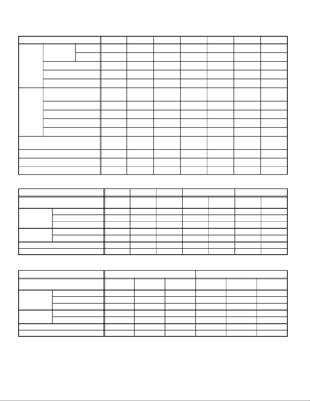
SPECIFICATIONS (Early Model)
Model No. HS26−261 HS26−311 HS26−411 HS26−461
Face area (sq.ft.)
Outdoor
Coil
Condenser
Fan
HCFC−22 (charge furnished)
Liquid line connection
Suction line connection
*Refrigerant charge sufficient for 25 ft. (7.6 m) length of refrigerant lines.
outer / inner
Tube diameter (in.)
No. of Rows
Fins per inch
Diameter (in.)
No. of Blades
Motor hp
Cfm
RPM
Watts
11.8/5.4 15.9/5.5 15.9/15.3 21.6/20.8
3/8 3/8 3/8 3/8
1.36 1.36 2.0 2.0
20 20 20 20
24 24 24 24
3333
1/6 1/6 1/6 1/6
3150 3150 3000 3230
820 820 820 820
210 210 230 205
7lbs. 11oz. 8lbs. 1oz. 9lbs. 0oz. 11lbs. 3oz.
3/8 3/8 3/8 3/8
3/4 3/4 3/4 11/8
ELECTRICAL DATA (Early Model)
Model No.
Line voltage data − 60hz./1 phase
Rated load amps
Compressor
Condenser
Fan Motor
Max fuse or c.b. size (amps)
*Minimum circuit ampacity
*Refer to National Electrical Code Manual to determine wire, fuse and disconnect size requirements.
NOTE − Extremes of operating range are plus 10% and minus 5% of line voltage
Power factor
Locked rotor amps
Full load amps
Locked rotor amps
HS26−261 HS26−311 HS26−411 HS26−461
208/230V 208/230V 208/230V 208/230V
11.6 13.5 18.0 20
.96 .96 .96 .97
62.5 76.0 90.5 107
1.1 1.1 1.1 1.1
2.0 2.0 2.0 2.0
25 30 40 45
15.6 18.0 23.6 26.1
Page 1
1996 Lennox Industries Inc.
Net face area
Condenser
Coil
Cond
Condenser Coil
Condenser Coil
Coil
SPECIFICATIONS (Late Model)
Model No. HS26018 HS26024 HS26030 HS26036 HS26042 HS26048 HS26060
Net face area
sq. ft. (m2)
Tube diameter in. (mm) 5/16 (7.9) 5/16 (7.9) 5/16 (7.9) 5/16 (7.9) 5/16 (7.9) 5/16 (7.9) 5/16 (7.9)
No. of rows 1.48 1.48 1.36 1.86 1.86 1.75 2
Fins per inch (m) 22 (866) 22 (866) 22 (866) 22 (866) 22 (866) 22 (866) 22 (866)
Outer coil 11.9 (1.11) 11.9 (1.11) 16.0 (1.59) 16.0 (1.59) 16.0 (1.59) 18.2 (1.69) 21.6 (2.01)
Inner coil 5.5 (0.51) 5.5 (0.51) 5.6 (0.52) 13.3 (1.24) 13.3 (1.24) 13.3 (1.24) 20.8 (1.93)
Dia. − in. (mm) no. of blades 20 (508) − 4 20 (508) − 4 24 (610) − 3 24 (610) − 3 24 (610) − 3
Motor hp (W) 1/10 (75) 1/6 (124) 1/6 (124) 1/6 (124) 1/6 (124) 1/4 (187) 1/4 (187)
enser
Fan Cfm (L/s) 2500 (1180) 2450 (1155) 3150 (1485) 3150 (1485) 3000 (1415) 3900 (1840) 4200 (1980)
Rpm 825 825 825 825 825 820 820
Watts 160 210 225 225 230 310 350
*Refrigerant HCFC22 charge furnished
Liquid line (o.d.) in. (mm) sweat 3/8 (9.5) 3/8 (9.5) 3/8 (9.5) 3/8 (9.5) 3/8 (9.5) 3/8 (9.5) 3/8 (9.5)
Suction line (o.d.) in. (mm) sweat 5/8 (16) 3/4 (19) 3/4 (19) 3/4 (19) 7/8 (22.2) 7/8 (22.2) 11/8 (28.6)
Shipping weight lbs. (kg) 1 package 177 (80) 185 (84) 192 (87) 221 (100) 231 (105) 274 (124) 308 (140)
*Refrigerant charge sufficient for 25 ft. (7.6 m) length of refrigerant lines.
4 lbs. 1 oz.
(1.84 kg)
4 lbs. 1 oz.
(1.84 kg)
5 lbs. 1 oz.
(2.30 kg)
5 lbs. 13 oz.
(2.64 kg)
6 lbs. 11 oz.
(3.03 kg)
24 (610) 424 (610)
7 lbs. 5 oz.
(3.32 kg)
4
10 lbs. 8 oz.
(4.76 kg)
ELECTRICAL DATA (Late Model)
Model No. HS26018 HS26024 HS26030 HS26036 HS26042
Line voltage data 60hz
Rated load amps 8.4 10.3 13.5 16.0 10.3 18.0 12.5
Compressor Power factor 0.97 0.96 0.96 0.96 0.82 0.94 0.82
Locked rotor amps 47 56 72.5 88 77 104 88
Condenser Coil
Fan Motor
Rec. max. fuse or circuit breaker size (amps) 15 20 30 35 20 40 25
*Minimum circuit ampacity 13 14 18 21.3 14 23.6 16.4
*Refer to National or Canadian Electrical Code manual to determine wire, fuse and disconnect size requirements.
NOTE Extremes of operating range are plus 10% and minus 5% of line voltage.
Full load amps 0.8 1.1 1.1 1.1 1.1 1.1 1.1
Locked rotor amps 1.6 2.0 2.0 2.0 2.0 2.0 2.0
208/230v
1ph
208/230v
1ph
208/230v
1ph
208/230v
1ph
208/230v
3ph
208/230v
1ph
208/230v
3ph
ELECTRICAL DATA (Late Model)
Model No. HS26048 HS26060
Line voltage data 60hz
Rated load amps 23.7 13.5 7.4 28.8 17.4 9.0
Compressor Power factor .97 .87 .87 .97 .85 .85
Locked rotor amps 129 99 49.5 169 123 62
Condenser Coil
Fan Motor
Rec. max. fuse or circuit breaker size (amps) 50 30 15 60 40 20
*Minimum circuit ampacity 31.4 18.6 10.4 37.7 23.5 12.4
*Refer to National or Canadian Electrical Code manual to determine wire, fuse and disconnect size requirements.
NOTE Extremes of operating range are plus 10% and minus 5% of line voltage.
Full load amps 1.7 1.7 1.1 1.7 1.7 1.1
Locked rotor amps 3.1 3.1 2.2 3.1 3.1 2.2
208/230v
1ph
208/230v
3ph
460v
3ph
208/230v
1ph
208/230v
3ph
460v
3ph
Page 2
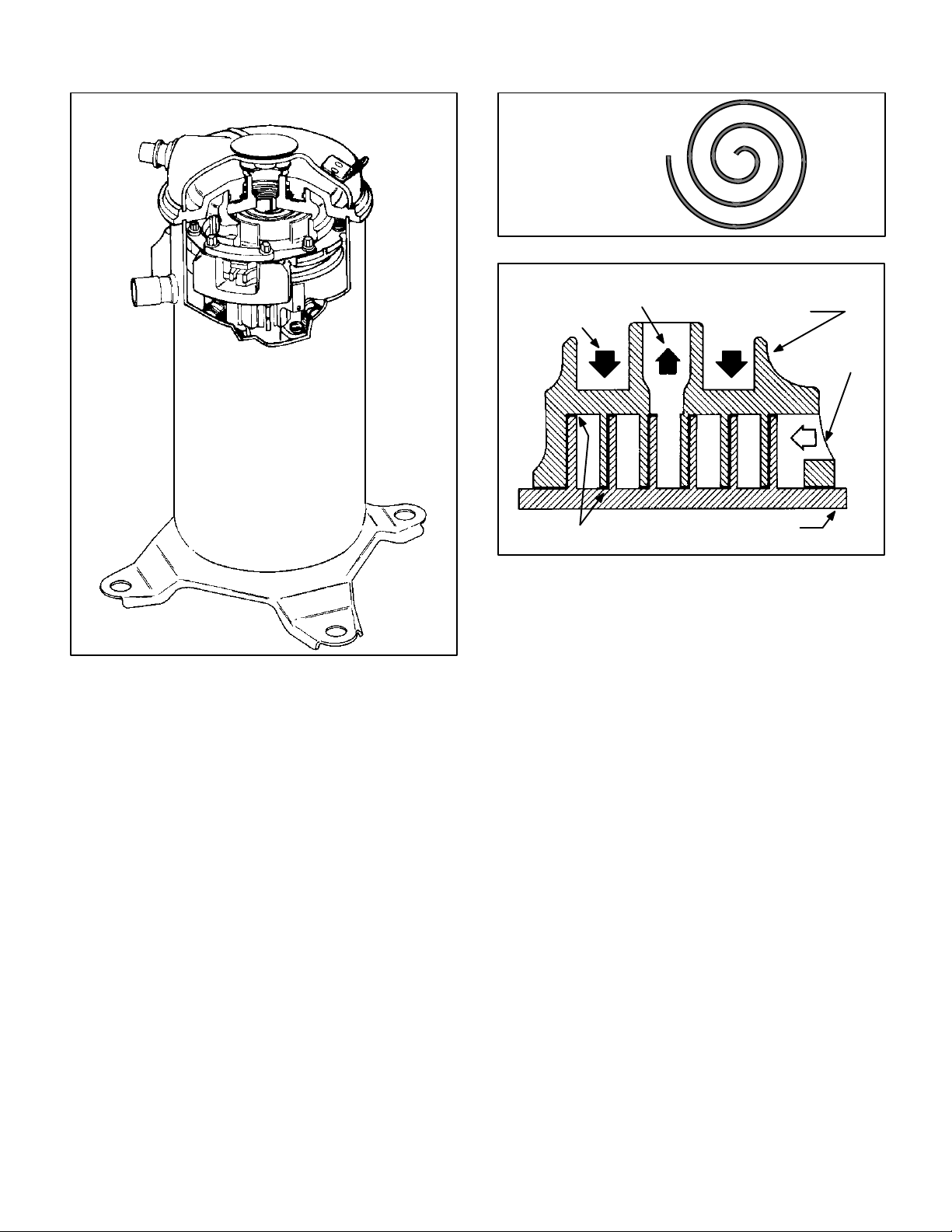
DISCHARGE
SUCTION
SCROLL COMPRESSOR
SCROLL FORM
CROSS−SECTION OF SCROLLS
DISCHARGE
DISCHARGE
PRESSURE
FIGURE 2
STATIONARY SCROLL
SUCTION
Early Model HS26
Compressor shown
FIGURE 1
I−APPLICATION
All major components (indoor blower and coil) must be
matched according to Lennox recommendations for the
compressor to be covered under warranty. Refer to the
Engineering Handbook for approved system matchups. A
misapplied system will cause erratic operation and can re
sult in early compressor failure.
II−SCROLL COMPRESSOR
The scroll compressor design is simple, efficient and re
quires few moving parts. A cutaway diagram of the scroll
compressor is shown in figure 1.The scrolls are located in
the top of the compressor can and the motor is located just
below. The oil level is immediately below the motor.
The scroll is a simple compression concept centered
around the unique spiral shape of the scroll and its inherent
properties. Figure 2 shows the basic scroll form. Two iden
tical scrolls are mated together forming concentric spiral
shapes (figure 3 ). One scroll remains stationary, while the
other is allowed to orbit" (figure 4). Note that the orbiting
scroll does not rotate or turn but merely orbits" the station
ary scroll.
TIPS SEALED BY
DISCHARGE PRESSURE
ORBITING SCROLL
FIGURE 3
The counterclockwise orbiting scroll draws gas into the out
er crescent shaped gas pocket created by the two scrolls
(figure 4 − 1). The centrifugal action of the orbiting scroll
seals off the flanks of the scrolls (figure 4 − 2). As the orbiting
motion continues, the gas is forced toward the center of the
scroll and the gas pocket becomes compressed (figure 4
−3). When the compressed gas reaches the center, it is dis
charged vertically into a chamber and discharge port in the
top of the compressor (figure1). The discharge pressure
forcing down on the top scroll helps seal off the upper and
lower edges (tips) of the scrolls (figure 3 ). During a single
orbit, several pockets of gas are compressed simultaneous
ly providing smooth continuous compression.
The scroll compressor is tolerant to the effects of liquid re
turn. If liquid enters the scrolls, the orbiting scroll is allowed
to separate from the stationary scroll. The liquid is worked
toward the center of the scroll and is discharged. If the
compressor is replaced, conventional Lennox cleanup
practices must be used.
Due to its efficiency, the scroll compressor is capable of
drawing a much deeper vacuum than reciprocating com
pressors. Deep vacuum operation can cause internal fu
site arcing resulting in damaged internal parts and will re
sult in compressor failure. Never use a scroll compressor
for evacuating or pumping−down" the system. This type of
damage can be detected and will result in denial of warran
ty claims.
NOTE − During operation, the head of a scroll compressor
may be hot since it is in constant contact with discharge
gas.
Page 3
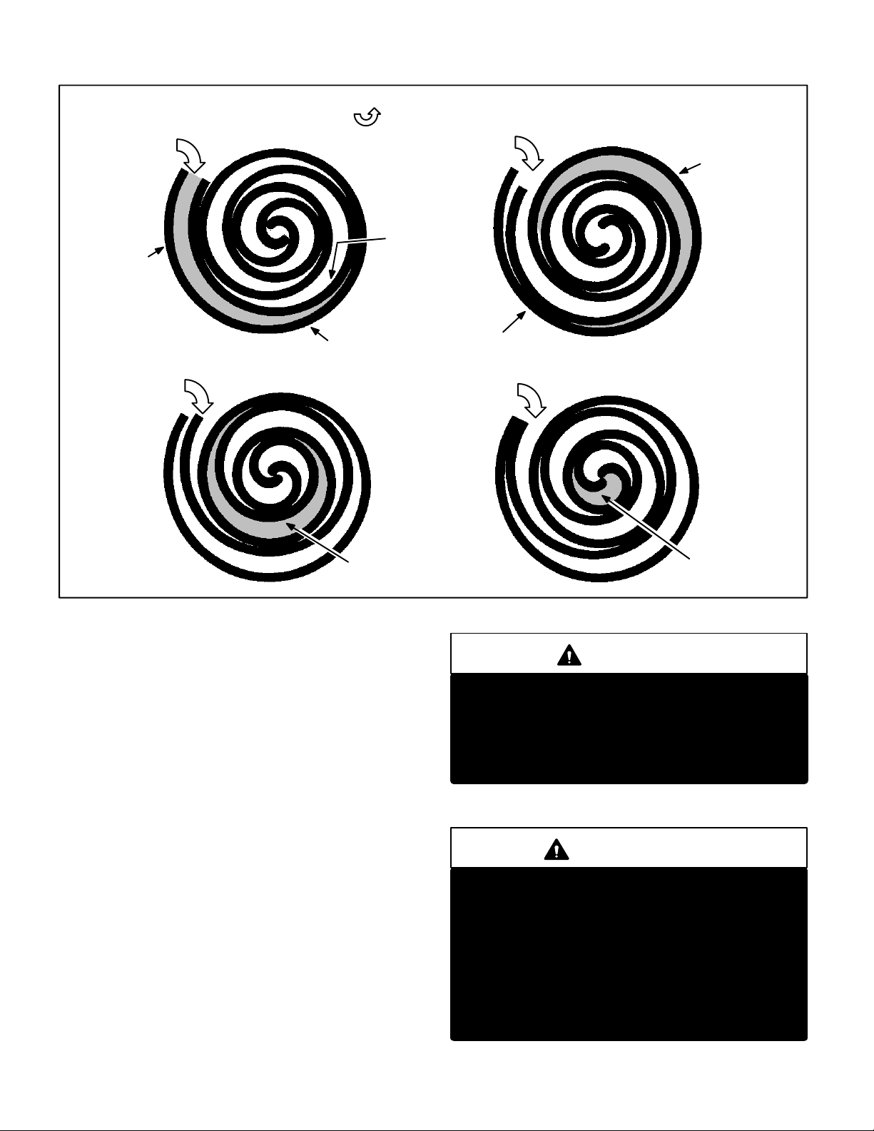
SUCTION
POCKET
HOW A SCROLL WORKS
MOVEMENT OF ORBIT
SUCTION
ORBITING
SCROLL
SUCTION
INTERMEDIATE
PRESSURE
GAS
CRESCENT
SHAPED GAS
POCKET
12
FLANKS
STATIONARY SCROLL
SUCTION
SEALED BY
CENTRIFUGAL
FORCE
SUCTION
34
HIGH
PRESSURE
GAS
FIGURE4
III−UNIT COMPONENTS
A−Transformer
The contactor coil, time delay and temperature sensor
are all energized by 24VAC supplied by the indoor unit.
All other controls in the outdoor unit are powered by line
voltage. Refer to unit wiring diagram. The HS26 is not
equipped with an internal line voltage to 24V transform
er.
B−Contactor
The compressor is energized by a contactor located in the
control box. Early model units use single−pole contactors.Late
model single−phase units use single pole and two−pole con
tactors. See wiring diagrams for specific unit. Late model
three−phase units use three−pole contactors. The contactor is
energized by indoor thermostat terminal Y when thermostat
demand is present.
DISCHARGE
POCKET
CAUTION
Some HS26 units use single−pole contactors. One
leg of the compressor, capacitor and condenser
fan are connected to line voltage at all times. Po
tential exists for electrical shock resulting in inju
ry or death. Remove all power at disconnect be
fore servicing
ELECTROSTATIC DISCHARGE (ESD)
Precautions and Procedures
CAUTION
Electrostatic discharge can affect electronic
components. Take precautions during unit instal
lation and service to protect the unit’s electronic
controls. Precautions will help to avoid control
exposure to electrostatic discharge by putting
the unit, the control and the technician at the
same electrostatic potential. Neutralize electro
static charge by touching hand and all tools on an
unpainted unit surface before performing any
service procedure.
Page 4
C−TD1−1 Time Delay (Early Models)
Some early model HS26 units are equipped with a Lennox−
built TD1−1 time delay located in the control box (figure 5).
The time delay is electrically connected between thermostat
terminal Y and the compressor contactor. On initial thermo
stat demand, the compressor contactor is delayed for 8.5
seconds. At the end of the delay, the compressor is allowed
to energize. When thermostat demand is satisfied, the time
delay opens the circuit to the compressor contactor coil and
the compressor is de−energized.
The time delay performs no other functions. Without the
delay it would be possible to short cycle the compressor. A
scroll compressor, when short cycled, can run backward if
head pressure is still high. It does not harm a scroll com
pressor to run backward, but it could cause a nuisance trip
of safety limits (internal overload). For this reason, if a
TD1−1 delay should fail, it must be replaced. Do not bypass
the control.
D−TOC Timed Off Control
(Early and Late Models)
Some early and all late model HS26 units are equipped with
a TOC, timed off control.The TOC is located in the control
box (figure 6). The time delay is electrically connected be
tween thermostat terminal Y and the compressor contactor.
Between cycles, the compressor contactor is delayed for 5
minutes + 2 minutes. At the end of the delay, the compres
sor is allowed to energize. When thermostat demand is sat
isfied, the time delay opens the circuit to the compressor
contactor coil and the compressor is de−energized. Without
the time delay it would be possible to short cycle the com
pressor. A scroll compressor, when short cycled, can run
backward if head pressure is still high. It does not harm a
scroll compressor to run backward, but it could cause a nui
sance tripout of safety limits. For this reason, if a TOC fails it
must be replaced.
DANGER
DO NOT ATTEMPT TO REPAIR THE TD1−1 OR THE
TOC CONTROL. UNSAFE OPERATION WILL RE
SULT. IF THE CONTROL IS FOUND TO BE INOP
ERATIVE, SIMPLY REPLACE IT.
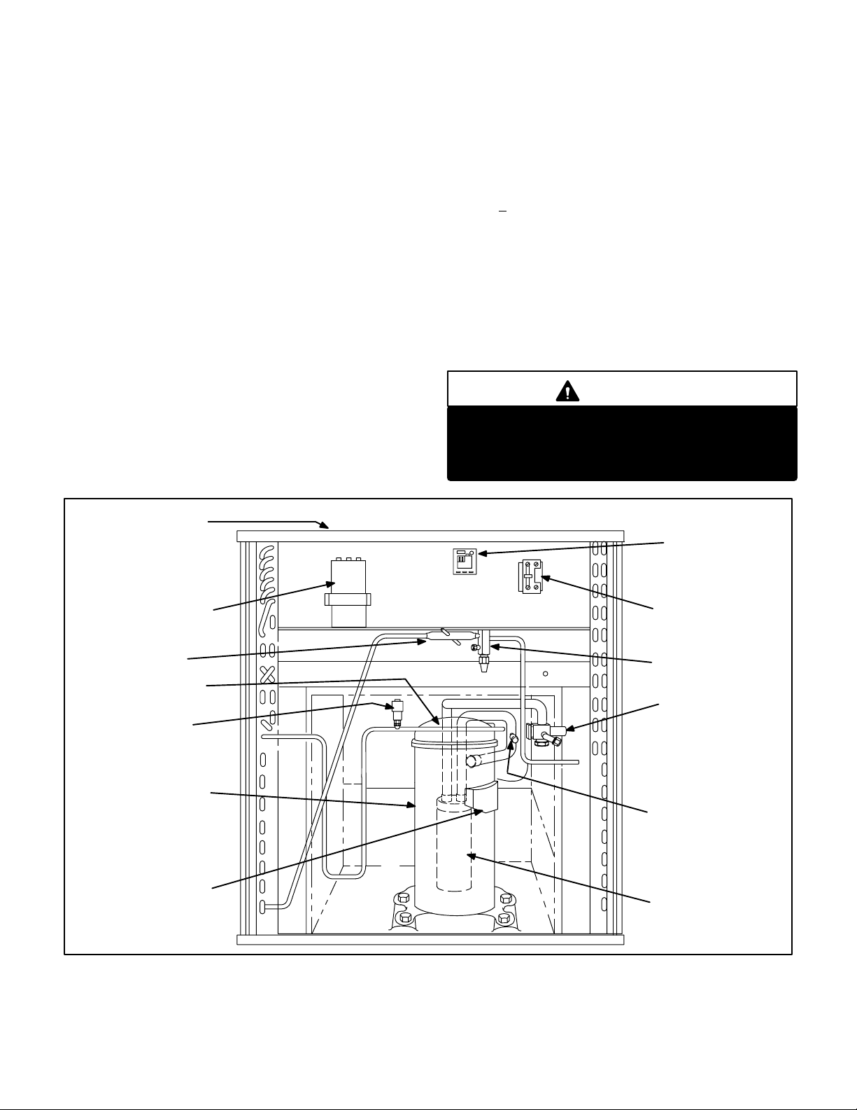
CONDENSER FAN
(NOT SHOWN)
TOP OF CABINET
DUAL CAPACITOR
THERMOMETER
WELL
COMPRESSOR
TEMPERATURE
SENSOR
HIGH
PRESSURE
SWITCH
COMPRESSOR
COMPRESSOR
TERMINAL BOX
HS26 UNIT COMPONENTS (EARLY MODEL)
TD−1 TIME DELAY
OR T.O.C. TIMED OFF
CONTROL
CONTACTOR
LIQUID LINE
SERVICE VALVE
AND GAUGE PORT
SUCTION
VALV E
AND GAUGE PORT
LOW PRES
SURE SWITCH
ACCUMULATOR
(411, 461 only
all others equipped
with suction muffler)
FIGURE 5
Page 5
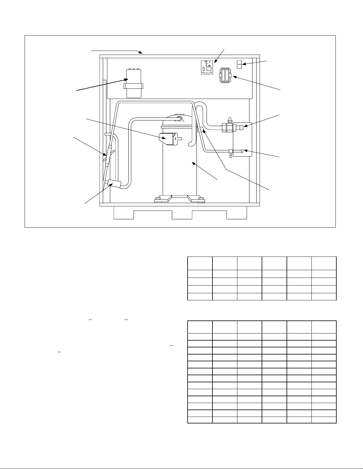
CONDENSER FAN
(NOT SHOWN)
TOP OF CABINET
PARTS ARRANGEMENT FOR HS26 (LATE MODEL)
TIMED OFF CONTROL (TOC)
GROUND LUG
DUAL CAPACITOR
TERMINAL BOX
THERMOME
TER
WELL
HIGH PRESSURE
SWITCH
FIGURE 6
E−Compressor
Tables1 and 2 show the specifications for compressors
used in HS26 series units.
F−Compressor High Temperature Limit
(Early Models)
Each scroll compressor in the HS26−261, −311, −411, −461
is equipped with a compressor high temperature limit lo
cated on the outside top of the compressor. The sensor is a
SPST thermostat which opens when the discharge tem
perature exceeds 280_F + 8_F (138_C + 4.5_C) on a tem
perature rise. When the switch opens, the circuit to the
compressor contactor and the time delay is de−energized
and the unit shuts off. The switch automatically resets
when the compressor temperature drops below 130_F +
14_F. (54_C + 8_C)
The sensor can be accessed by prying off the snap plug on
top of the compressor (see figure 7). Make sure to securely
seal the limit after replacement. The limit pigtails are lo
cated inside the unit control box. Figure 8 shows the ar
rangement of compressor line voltage terminals and dis
charge sensor pigtails.
CONTACTOR
SUCTION VALVE
AND GAUGE PORT
LIQUID LINE
SERVICE VALVE
AND GAUGE
PORT
COMPRESSOR
LOW PRESSURE
SWITCH
Table 1 (Early Models)
HS 26
Unit
−261 208/230 1 62.5 11.6 28*
−311 208/230 1 76.0 13.5 28*
−411 208/230 1 90.5 18.0 34*
−461 208/230 1 107 20.0 38*
*Shipped with conventional white oil (Sontex 200LT). 3GS oil may be
used if additional oil is required.
Vac Phase LRA RLA Oil fl.oz.
Table 2 (Late Models)
HS26
Unit
−018 208/230 1 47.0 8.4 38*
−024 208/230 1 56.0 10.3 30*
−030 208/230 1 72.5 13.5 30*
−036 208/230 1 88.0 16.0 42*
−042 208/230 1 104.0 18.0 42*
−048 208/230 1 129.0 23.7 53*
−060 208/230 1 169.0 28.8 50*
−036 208/230 3 88.8 10.3 42*
−042 208/230 3 77.0 12.5 42*
−048 208/230 3 99.0 13.5 53*
−048 460 3 49.5 7.4 53*
−060 208/230 3 123.0 17.4 53*
−060 460 3 62.0 9.0 53*
*Shipped with conventional white oil (Sontex 200LT). 3GS oil may be
used if additional oil is required.
Vac Phase LRA RLA Oil fl. oz.
Page 6
 Loading...