

SERVICE
INFORMATION
Corp. 9327-L3 Litho U.S.A.
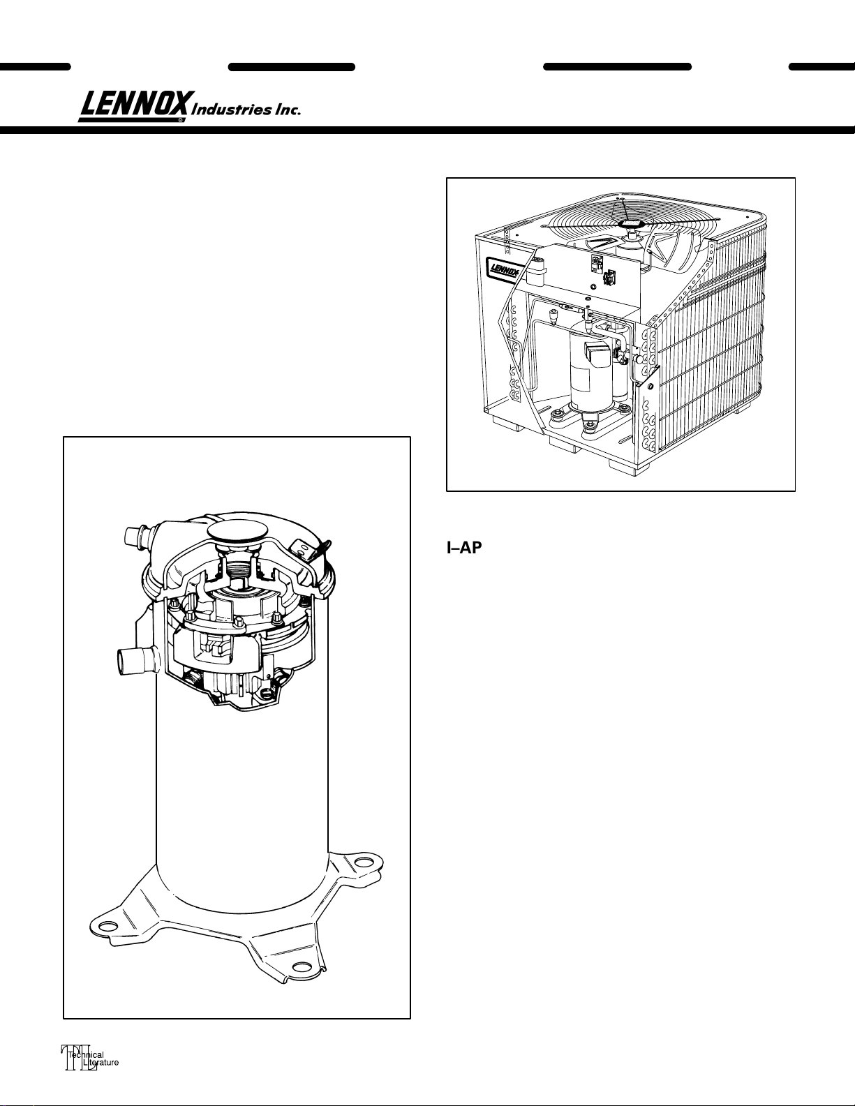
HS25 SERIES UNITS
The HS25 is a high efficiency residential split–system
condensing unit which features a scroll compressor. It
operates much like a standard condensing unit, but the
HS25’s scroll compressor is unique in the way that it
compresses refrigerant. Several models are available in
sizes ranging from 1–1/2 through 5 tons. The series is designed for use with an expansion valve in the indoor unit.
This manual is divided into sections which discuss the
major components, refrigerant system, charging procedure, maintenance and operation sequence.
All specifications in this manual are subject to change.
UNIT
HS25
DISCHARGE
SUCTION
SCROLL COMPRESSOR
I–APPLICATION
All major components (indoor blower/coil) must be
matched according to Lennox recommendations for
the compressor to be covered under warranty. Refer to
the Engineering Handbook for approved system
matchups. A misapplied system will cause erratic operation and can result in early compressor failure.
II–SCROLL COMPRESSOR
The scroll compressor design is simple, efficient and
requires few moving parts. A cutaway diagram of the
scroll compressor is shown on the cover. The scrolls
are located in the top of the compressor can and the
motor is located just below. The oil level is immediately below the motor.
The scroll is a simple compression concept centered
around the unique spiral shape of the scroll and its inherent properties. Figure 1 shows the basic scroll form.
Two identical scrolls are mated together forming concentric spiral shapes (figure 2). One scroll remains stationary, while the other is allowed to orbit (figure 3).
Note that the orbiting scroll does not rotate or turn but
merely orbits the stationary scroll.
1993 Lennox Industries Inc.
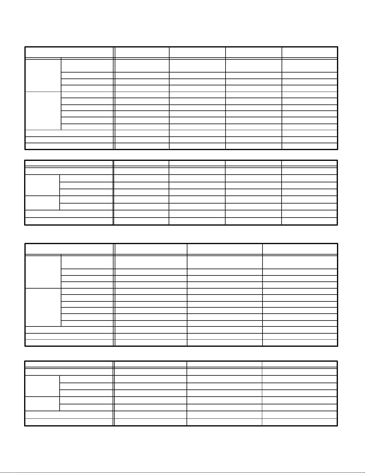
SPECIFICATIONS
Model No. HS25–261 HS25–311 HS25–411
HS25–211
Face area (sq.ft.)
Outdoor
Coil
Condenser
Fan
HCFC–22 (charge furnished)
Liquid line connection
Suction line connection
inner / outer
Tube diameter (in.)
No. of Rows
Fins per inch
Diameter (in.)
No. of Blades
Motor hp
Cfm
RPM
Watts
- - -/11.8 5.4/11.8 5.5/15.9
3/8 3/8 3/8 3/8
1.0 1.48 1.36 1.36
20 20 20 20
20 20 24 24
44 33
1/6 1/6 1/6 1/6
2600 2450 3150 3150
820 820 820 820
200 210 215 210
6lbs. 2oz. 6lbs. 8oz. 8lbs. 1oz. 8lbs. 1oz.
3/8 3/8 3/8 3/8
5/8 3/4 3/4 3/4
ELECTRICAL DATA
Model No.
Line voltage data – 60hz./1 phase
Rated load amps
Compressor
Condenser
Fan Motor
Max fuse or c.b. size (amps)
*Minimum circuit ampacity
*Refer to National Electrical Code Manual to determine wire, fuse and disconnect size requirements.
NOTE – Extremes of operating range are plus 10% and minus 5% of line voltage
Power factor
Locked rotor amps
Full load amps
Locked rotor amps
HS25–211
208/230V 208/230V 208/230V 208/230V
9.7
.96
50.0
1.1 1.1 1.1 1.1
2.0 2.0 2.0 2.0
20
13.3
HS25–261 HS25–311 HS25–411
SPECIFICATIONS
Model No. HS25–511 HS25–651HS25–461
5.5/15.9
11.6 13.5 18.0
.96 .96 .96
62.5 76.0 90.5
25 30 40
15.6 18.0 23.6
Face area (sq.ft.)
Outdoor
Coil
Condenser
Fan
HCFC–22 (charge furnished)
Liquid line connection
Suction line connection
inner / outer
Tube diameter (in.)
No. of Rows
Fins per inch
Diameter (in.)
No. of Blades
Motor hp
Cfm
RPM
Watts
ELECTRICAL DATA
Model No.
Line voltage data – 60hz./1 phase
Rated load amps
Compressor
Condenser
Fan Motor
Max fuse or c.b. size (amps)
*Minimum circuit ampacity
*Refer to National Electrical Code Manual to determine wire, fuse and disconnect size requirements.
NOTE – Extremes of operating range are plus 10% and minus 5% of line voltage
Power factor
Locked rotor amps
Full load amps
Locked rotor amps
20.8/21.6 20.8/21.68.8/15.9
3/8 3/83/8
2.0 2.01.57
20 2020
24 2424
443
1/4 1/41/6
3870 42503100
840 820820
330 350205
13lbs. 8oz. 15lbs. 8oz.8lbs. 5oz.
3/8 3/83/8
7/8 1-1/87/8
HS25–511 HS25–651HS25–461
208/230V 208/230V208/230V
23.7 28.820
.89 0.97.97
129 169107
1.7 1.61.1
3.1 3.82.0
50 6045
31.3 37.726.1
Page 2
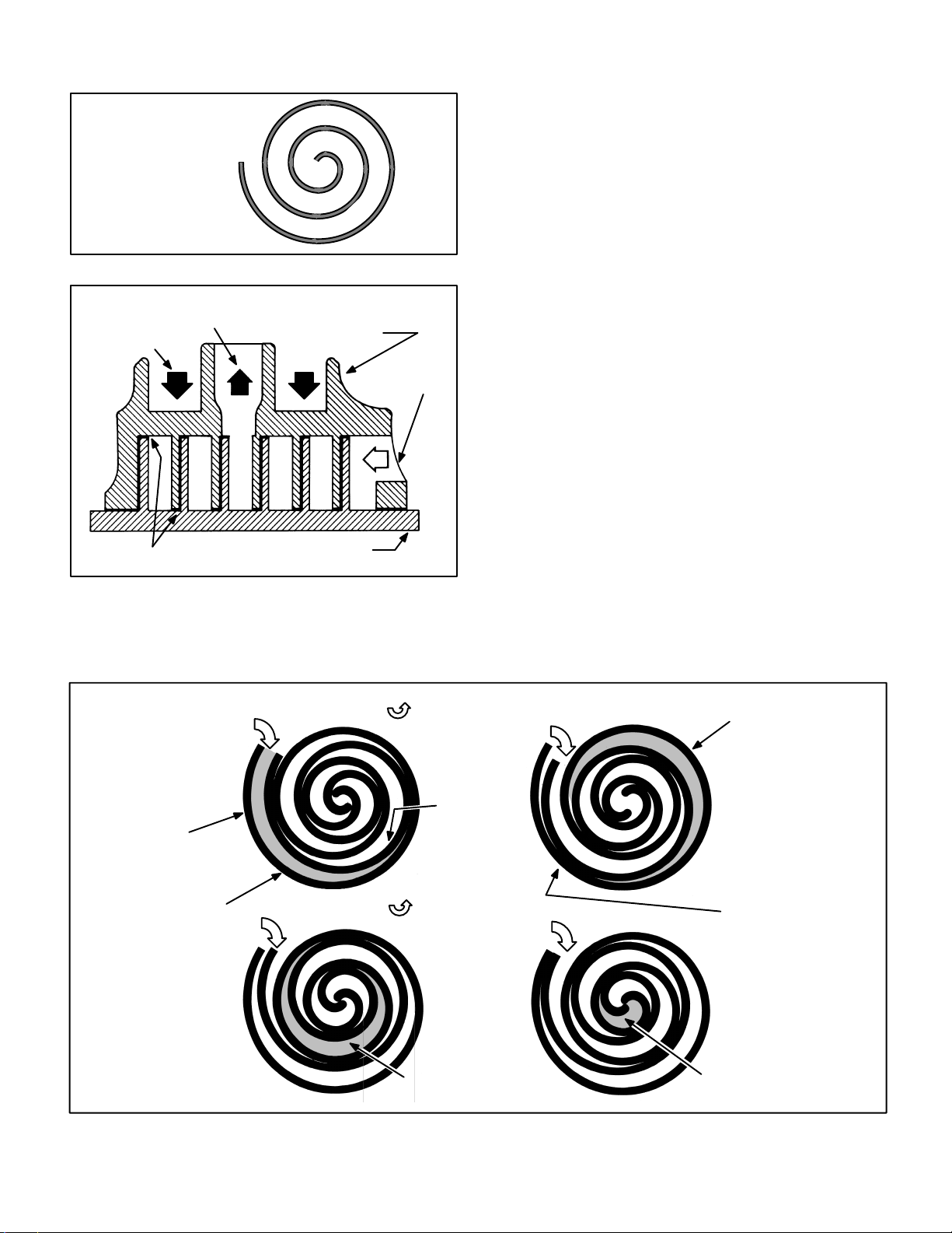
SCROLL FORM
FIGURE 1
CROSS–SECTION OF SCROLLS
DISCHARGE
DISCHARGE
PRESSURE
TIPS SEALED BY
DISCHARGE PRESSURE
STATIONARY SCROLL
SUCTION
ORBITING SCROLL
FIGURE 2
NOTE – During operation, the head of a scroll compressor may be hot since it is in constant contact
with discharge gas.
The counterclockwise orbiting scroll draws gas into the
outer crescent shaped gas pocket created by the two
scrolls (figure 3 – 1). The centrifugal action of the orbiting scroll seals off the flanks of the scrolls (figure 3 – 2).
As the orbiting motion continues, the gas is forced toward the center of the scroll and the gas pocket becomes compressed (figure 3 – 3). When the compressed gas reaches the center, it is discharged vertically into a chamber and discharge port in the top of the
compressor (figure 2). The discharge pressure forcing
down on the top scroll helps seal off the upper and lower edges (tips) of the scrolls (figure 2). During a single
orbit, several pockets of gas are compressed simultaneously providing smooth continuous compression.
The scroll compressor is tolerant to the effects of liquid
return. If liquid enters the scrolls, the orbiting scroll is
allowed to separate from the stationary scroll. The liquid is worked toward the center of the scroll and is discharged. If the compressor is replaced, conventional
Lennox cleanup practices must be used.
Due to its efficiency, the scroll compressor is capable
of drawing a much deeper vacuum than reciprocating
compressors. Deep vacuum operation can cause internal fusite arcing resulting in damaged internal parts
and will result in compressor failure. Never use a scroll
compressor for evacuating or “pumping–down” the
system. This type of damage can be detected and will
result in denial of warranty claims.
SUCTION
POCKET
STATIONARY SCROLL
HOW A SCROLL WORKS
SUCTION
MOVEMENT OF ORBIT
SUCTION
ORBITING
SCROLL
INTERMEDIATE
PRESSURE
GAS
CRESCENT
SHAPED GAS
POCKET
12
FLANKS
SEALED BY
CENTRIFUGAL FORCE
SUCTION
MOVEMENT OF ORBIT
SUCTION
34
HIGH
PRESSURE GAS
FIGURE 3
DISCHARGE
POCKET
Page 3
 Loading...