

Page 1
SERVICE
INFORMATION
Corp. 9327-L3 Litho U.S.A.
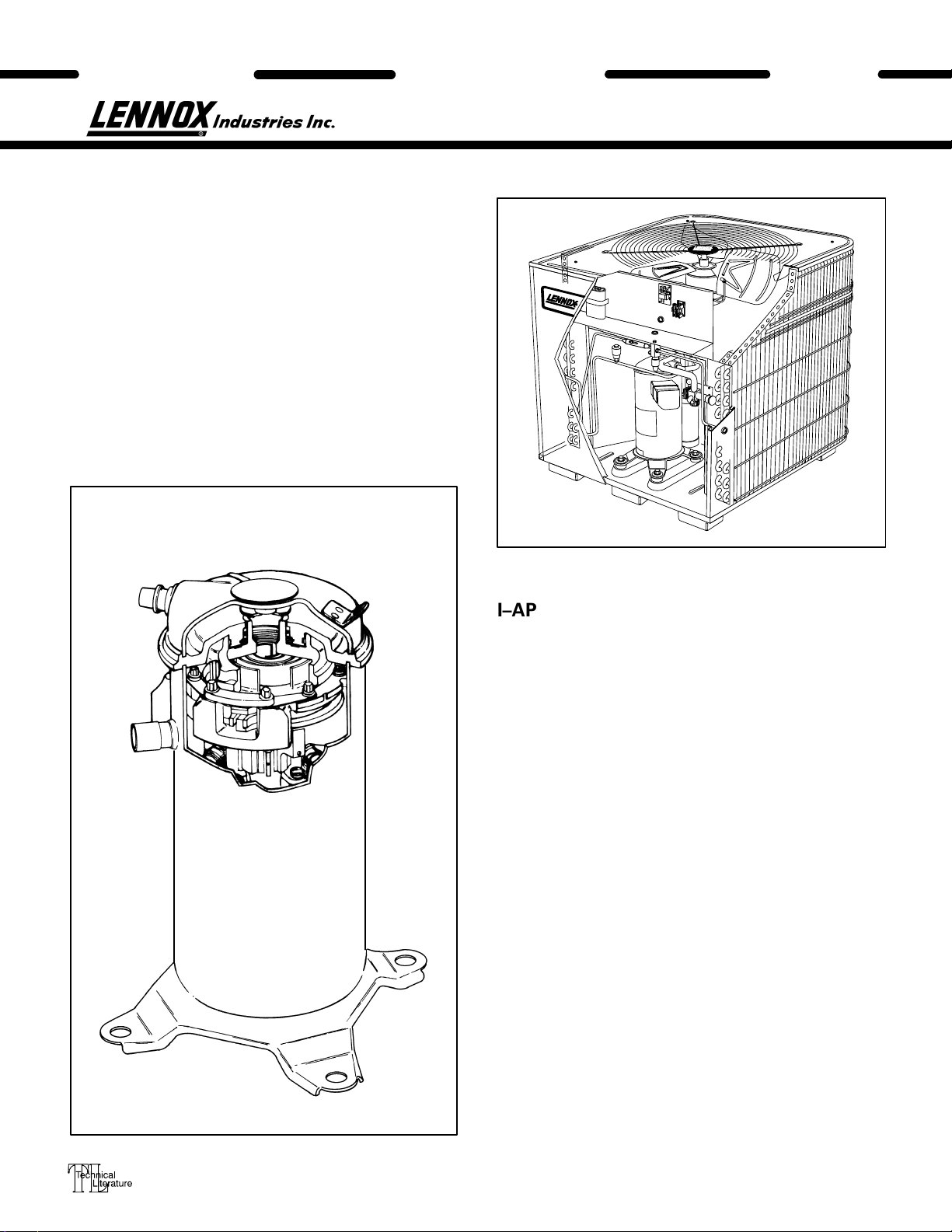
HS25 SERIES UNITS
The HS25 is a high efficiency residential split–system
condensing unit which features a scroll compressor. It
operates much like a standard condensing unit, but the
HS25’s scroll compressor is unique in the way that it
compresses refrigerant. Several models are available in
sizes ranging from 1–1/2 through 5 tons. The series is designed for use with an expansion valve in the indoor unit.
This manual is divided into sections which discuss the
major components, refrigerant system, charging procedure, maintenance and operation sequence.
All specifications in this manual are subject to change.
UNIT
HS25
DISCHARGE
SUCTION
SCROLL COMPRESSOR
I–APPLICATION
All major components (indoor blower/coil) must be
matched according to Lennox recommendations for
the compressor to be covered under warranty. Refer to
the Engineering Handbook for approved system
matchups. A misapplied system will cause erratic operation and can result in early compressor failure.
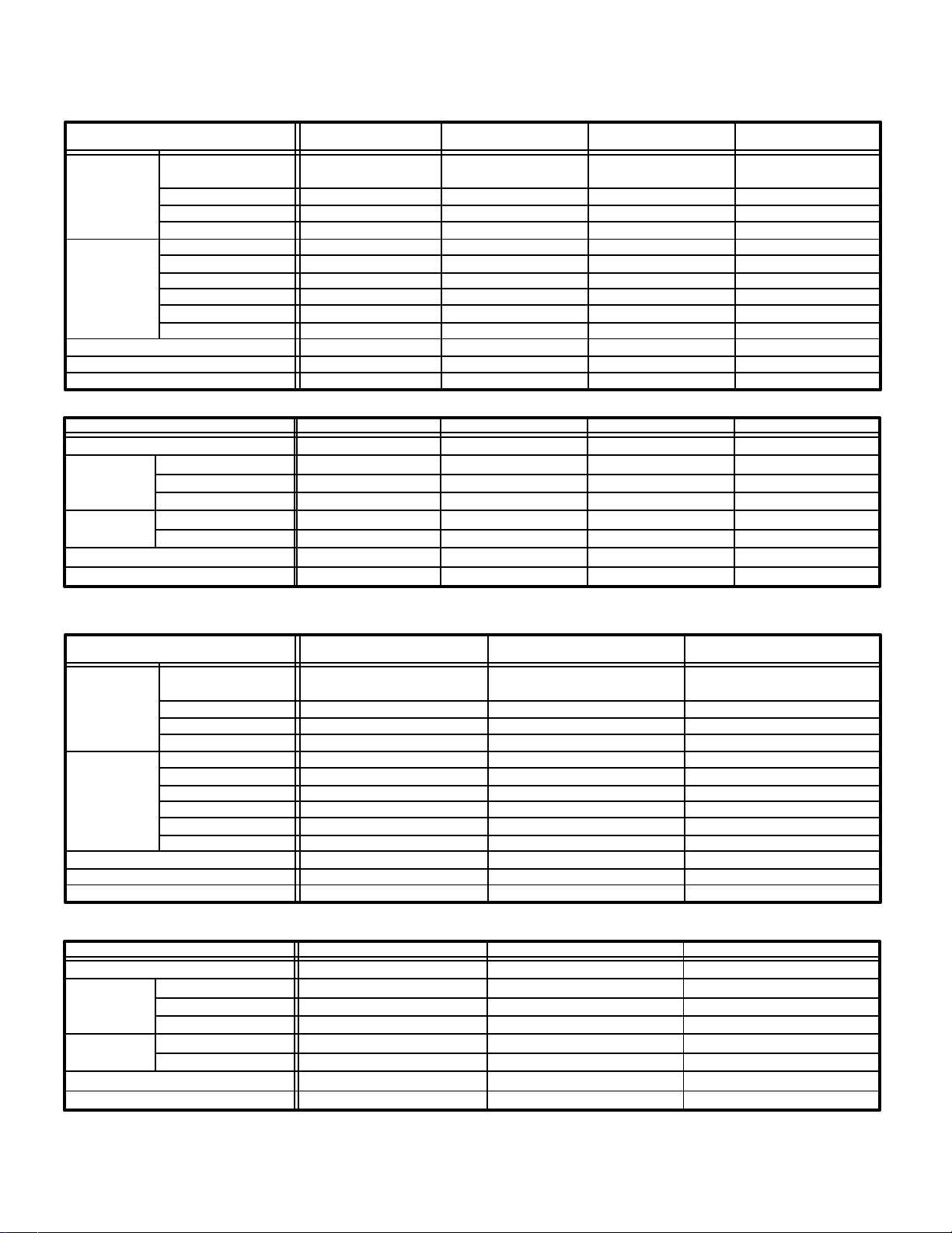
II–SCROLL COMPRESSOR
The scroll compressor design is simple, efficient and
requires few moving parts. A cutaway diagram of the
scroll compressor is shown on the cover. The scrolls
are located in the top of the compressor can and the
motor is located just below. The oil level is immediately below the motor.
The scroll is a simple compression concept centered
around the unique spiral shape of the scroll and its inherent properties. Figure 1 shows the basic scroll form.
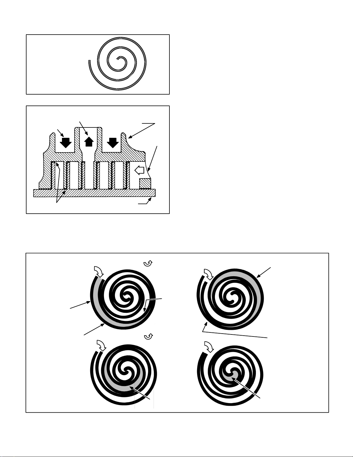
Two identical scrolls are mated together forming concentric spiral shapes (figure 2). One scroll remains stationary, while the other is allowed to orbit (figure 3).
Note that the orbiting scroll does not rotate or turn but
merely orbits the stationary scroll.
1993 Lennox Industries Inc.
Page 2
SPECIFICATIONS
Model No. HS25–261 HS25–311 HS25–411
HS25–211
Face area (sq.ft.)
Outdoor
Coil
Condenser
Fan
HCFC–22 (charge furnished)
Liquid line connection
Suction line connection
inner / outer
Tube diameter (in.)
No. of Rows
Fins per inch
Diameter (in.)
No. of Blades
Motor hp
Cfm
RPM
Watts
- - -/11.8 5.4/11.8 5.5/15.9
3/8 3/8 3/8 3/8
1.0 1.48 1.36 1.36
20 20 20 20
20 20 24 24
44 33
1/6 1/6 1/6 1/6
2600 2450 3150 3150
820 820 820 820
200 210 215 210
6lbs. 2oz. 6lbs. 8oz. 8lbs. 1oz. 8lbs. 1oz.
3/8 3/8 3/8 3/8
5/8 3/4 3/4 3/4
ELECTRICAL DATA
Model No.
Line voltage data – 60hz./1 phase
Rated load amps
Compressor
Condenser
Fan Motor
Max fuse or c.b. size (amps)
*Minimum circuit ampacity
*Refer to National Electrical Code Manual to determine wire, fuse and disconnect size requirements.
NOTE – Extremes of operating range are plus 10% and minus 5% of line voltage
Power factor
Locked rotor amps
Full load amps
Locked rotor amps
HS25–211
208/230V 208/230V 208/230V 208/230V
9.7
.96
50.0
1.1 1.1 1.1 1.1
2.0 2.0 2.0 2.0
20
13.3
HS25–261 HS25–311 HS25–411
SPECIFICATIONS
Model No. HS25–511 HS25–651HS25–461
5.5/15.9
11.6 13.5 18.0
.96 .96 .96
62.5 76.0 90.5
25 30 40
15.6 18.0 23.6
Face area (sq.ft.)
Outdoor
Coil
Condenser
Fan
HCFC–22 (charge furnished)
Liquid line connection
Suction line connection
inner / outer
Tube diameter (in.)
No. of Rows
Fins per inch
Diameter (in.)
No. of Blades
Motor hp
Cfm
RPM
Watts
ELECTRICAL DATA
Model No.
Line voltage data – 60hz./1 phase
Rated load amps
Compressor
Condenser
Fan Motor
Max fuse or c.b. size (amps)
*Minimum circuit ampacity
*Refer to National Electrical Code Manual to determine wire, fuse and disconnect size requirements.
NOTE – Extremes of operating range are plus 10% and minus 5% of line voltage
Power factor
Locked rotor amps
Full load amps
Locked rotor amps
20.8/21.6 20.8/21.68.8/15.9
3/8 3/83/8
2.0 2.01.57
20 2020
24 2424
443
1/4 1/41/6
3870 42503100
840 820820
330 350205
13lbs. 8oz. 15lbs. 8oz.8lbs. 5oz.
3/8 3/83/8
7/8 1-1/87/8
HS25–511 HS25–651HS25–461
208/230V 208/230V208/230V
23.7 28.820
.89 0.97.97
129 169107
1.7 1.61.1
3.1 3.82.0
50 6045
31.3 37.726.1
Page 2
Page 3
SCROLL FORM
FIGURE 1
CROSS–SECTION OF SCROLLS
DISCHARGE
DISCHARGE
PRESSURE
TIPS SEALED BY
DISCHARGE PRESSURE
STATIONARY SCROLL
SUCTION
ORBITING SCROLL
FIGURE 2
NOTE – During operation, the head of a scroll compressor may be hot since it is in constant contact
with discharge gas.
The counterclockwise orbiting scroll draws gas into the
outer crescent shaped gas pocket created by the two
scrolls (figure 3 – 1). The centrifugal action of the orbiting scroll seals off the flanks of the scrolls (figure 3 – 2).
As the orbiting motion continues, the gas is forced toward the center of the scroll and the gas pocket becomes compressed (figure 3 – 3). When the compressed gas reaches the center, it is discharged vertically into a chamber and discharge port in the top of the
compressor (figure 2). The discharge pressure forcing
down on the top scroll helps seal off the upper and lower edges (tips) of the scrolls (figure 2). During a single
orbit, several pockets of gas are compressed simultaneously providing smooth continuous compression.
The scroll compressor is tolerant to the effects of liquid
return. If liquid enters the scrolls, the orbiting scroll is
allowed to separate from the stationary scroll. The liquid is worked toward the center of the scroll and is discharged. If the compressor is replaced, conventional
Lennox cleanup practices must be used.
Due to its efficiency, the scroll compressor is capable
of drawing a much deeper vacuum than reciprocating
compressors. Deep vacuum operation can cause internal fusite arcing resulting in damaged internal parts
and will result in compressor failure. Never use a scroll
compressor for evacuating or “pumping–down” the
system. This type of damage can be detected and will
result in denial of warranty claims.
SUCTION
POCKET
STATIONARY SCROLL
HOW A SCROLL WORKS
SUCTION
MOVEMENT OF ORBIT
SUCTION
ORBITING
SCROLL
INTERMEDIATE
PRESSURE
GAS
CRESCENT
SHAPED GAS
POCKET
12
FLANKS
SEALED BY
CENTRIFUGAL FORCE
SUCTION
MOVEMENT OF ORBIT
SUCTION
34
HIGH
PRESSURE GAS
FIGURE 3
DISCHARGE
POCKET
Page 3
Page 4

III–UNIT COMPONENTS
A–Transformer
The contactor coil, time delay and temperature sensor are all energized by 24VAC supplied by the indoor
unit. All other controls in the outdoor unit are powered by line voltage. Refer to unit wiring diagram.
The HS25 is not equipped with an internal line voltage to 24V transformer.
B–Contactor
The compressor is energized by a contactor located in
the control box. HS25-211 through -511 units use SPST
contactors. HS25-651 units use a DPST contactor. The
contactor is energized by indoor thermostat terminal Y
when thermostat demand is present.
WARNING
HS25 UNITS USING SINGLE-POLE CONTACTORS:
ONE LEG OF COMPRESSOR, CAPACITOR AND
CONDENSER FAN ARE CONNECTED TO LINE
VOLTAGE AT ALL TIMES. POTENTIAL EXISTS FOR
ELECTRICAL SHOCK RESULTING IN INJURY OR
DEATH. REMOVE ALL POWER AT DISCONNECT
BEFORE SERVICING.
C–TD1–1 Time Delay
Each HS25 is equipped with a Lennox built TD1–1 time
delay located in the control box (figure 4). The time
delay is electrically connected between thermostat terminal Y and the compressor contactor. On initial thermostat demand, the compressor contactor is delayed
for 8.5 seconds. At the end of the delay, the compressor
is allowed to energize. When thermostat demand is satisfied, the time delay opens the circuit to the compressor contactor coil and the compressor is de–energized.
The time delay performs no other functions. Without
the delay it would be possible to short cycle the compressor. A scroll compressor, when short cycled, can
run backward if head pressure is still high. It does not
harm a scroll compressor to run backward, but it could
cause a nuisance tripout of safety limits (internal overload). For this reason, if a TD1–1 delay should fail, it
must be replaced. Do not bypass the control.
DANGER
DO NOT ATTEMPT TO REPAIR THIS CONTROL.
UNSAFE OPERATION WILL RESULT. IF THE CONTROL IS FOUND TO BE INOPERATIVE, SIMPLY REPLACE THE ENTIRE CONTROL.
CONDENSER FAN
(NOT SHOWN)
TOP OF CABINET
DUAL CAPACITOR
THERMOMETER
WELL
COMPRESSOR
TEMPERATURE
SENSOR
HIGH
PRESSURE
SWITCH
COMPRESSOR
COMPRESSOR
TERMINAL BOX
HS25 UNIT COMPONENTS
TD1–1
TIME DELAY
CONTACTOR
LIQUID LINE
SERVICE VALVE
AND GAUGE PORT
SUCTION LINE
SERVICE VALVE
AND GAUGE PORT
LOW
PRESSURE
SWITCH
ACCUMULATOR
HS25-511/651
ONLY
FIGURE 4
Page 4
Page 5

D–Compressor
Table 1 shows the specifications of compressors used
in HS25 series units.
TABLE 1
Unit Phase LRA RLA
HS25–211 1 50.0 9.7 24*
HS25–261
HS25–311
HS25–411
HS25–461
HS25–511
HS25–651
*Shipped with conventional white oil (Sontex 200LT). 3GS oil
may be used if additional oil is required.
1
1
1
1
1
1
62.5
76.0
90.5
107
129
169
11.6
13.5
18.0
20.0
23.7
28.8
Oil
fl.oz.
28*
28*
34*
38*
52*
54*
E–Temperature Sensor
Scroll compressors up to 3-1/2 tons are equipped with
a temperature sensor located on the outside top of the
compressor. The sensor is a SPST thermostat which
opens when the discharge temperature exceeds 280F
+ 8F on a temperature rise. When the switch opens,
the circuit to the compressor contactor and the time
delay is de–energized and the unit shuts off. The switch
automatically resets when the compressor temperature drops below 130F + 14F.
The sensor can be accessed by prying off the snap plug
on top of the compressor (see figure 6). Make sure to
securely seal the sensor after replacement. The sensor
pigtails are located inside the unit control box. Figure 5
shows the arrangement of compressor line voltage
terminals and discharge sensor pigtails.
COMPRESSOR TERMINAL BOX
DISCHARGE TEMPERATURE
SENSOR WIRES
TO CONTROL BOX
(TO COMP. TERM. BOX IN
-461 UNITS)
3-1/2 TON
AND SMALLER ONLY
COMPRESSOR
TERMINALS
C
S
R
WARNING
COMPRESSOR MUST BE GROUNDED. DO
NOT OPERATE WITHOUT PROTECTIVE COVER
OVER TERMINALS. DISCONNECT ALL POWER
BEFORE REMOVING PROTECTIVE COVER.
DISCHARGE CAPACITORS BEFORE SERVICING
UNIT. COMPRESSOR WIRING DIAGRAM IS
FURNISHED INSIDE COMPRESSOR TERMINAL
BOX COVER. FAILURE TO FOLLOW THESE
PRECAUTIONS COULD CAUSE ELECTRICAL
SHOCK RESULTING IN INJURY OR DEATH.
FIGURE 5
F–High Pressure Switch
A manual-reset single-pole single-throw high pressure
switch located in the discharge line of the compressor
shuts off the compressor when discharge pressure rises
above the factory setting. The switch is normally closed
and is permanently adjusted to trip (open) at 410 + 10 psi.
See figure 4 for reset switch location.
SCROLL HIGH TEMPERATURE LIMIT CHANGEOUT (3-1/2 ton and smaller only)
SEALANT
(BLUE)
THERMAL GREASE
(WHITE)
COMPRESSOR
PLASTIC CAP
PRONG
GROMMET
LIMIT
(THERMOSTAT)
Instructions
1- With power off, disconnect wiring to limit.
2- Dislodge limit/cap assembly from compressor. Plastic cap and sili-
cone seal will break away. Discard all pieces.
3- Remove thermostat and grommet from compressor. Thoroughly
clean all blue adhesive and white silicone thermal grease from compressor and the inside of the thermostat tube. Thermostat tube should
be clean and free of debris.
4- Using Lennox kit 93G8601, dip end of thermostat into plastic bottle la-
beled “Silicone Thermal Grease G.E. #G641” and coat end of thermostat. Carefully insert thermostat/grommet assembly into thermostat
tube of compressor. Avoid contact with top of compressor.
5- Clean excess thermal grease from under cap lip and top lip of com-
pressor opening.
6- Install protector assembly as shown, feeding wire leads through
channel provided in cap.
7- Apply a bead of sealant around lip of cap at area shown in illustration
and into the thermostat tube area.
8- Install assembly as shown. Align wires to channel in compressor
shell. Sufficient force is required to snap plastic cap into tube to en-
gage all three prongs.
9- Re-connect wiring.
10-After completing thermostat replacement, discard remaining parts.
FIGURE 6
Page 5
Page 6

G–Low Pressure Switch
An auto-reset single-pole single-throw low pressure
switch located in the suction line of the compressor
shuts off the compressor when suction pressure drops
below the factory setting. The switch is normally
closed and is permanently adjusted to trip (open) at 25
+ 5 psi. The switch automatically resets when suction
line pressure rises above 55 + 5 psi. See figure 4 for reset switch location.
H–Dual Capacitor
The compressor and fan on all models use permanent
split capacitor motors. A single “dual” capacitor is used
for both the fan motor and the compressor (see unit wiring diagram). The fan side of the capacitor and the compressor side of the capacitor have different mfd ratings.
The capacitor is located inside the unit control box (see
figure 4). Table 2 shows the ratings of the dual capacitor.
TABLE 2
Units MFD VAC
HS25–211
HS25–261
HS25–311
HS25–411, -461
HS25–511
HS25–651
HS25 DUAL CAPACITOR RATING
Terminal
FAN
HERM
FAN
HERM
FAN
HERM
FAN
HERM
FAN
HERM
FAN
HERM
25
30
35
35
10
40
10
55
5
5
5
5
370
440
I–Condenser Fan Motor
All units use single–phase PSC fan motors which require a run capacitor. The “FAN” side of the dual capacitor is used for this purpose. The specifications table on
page 1 of this manual shows the specifications of outdoor fans used in HS25s. In all units, the outdoor fan is
controlled by the compressor contactor.
IV–REFRIGERANT SYSTEM
A–Plumbing
Field refrigerant piping consists of liquid and suction
lines from the outdoor unit (sweat connections). Use
Lennox L10 series line sets as shown in table 3 or field
fabricated refrigerant lines. Refer to the piping section
of the Lennox Service Unit Information Manual
(SUI–803–L9) for proper size, type and application of
field–fabricated lines.
Separate discharge and suction service ports are provided at the compressor for connection of gauge manifold during charging procedure.
TABLE 3
Model No.
HS25–211
HS25–261
HS25–311
HS25–411
HS25–461
HS25-511
LIQUID SUCTION L10
LINE LINE LINE SETS
3/8 in. 5/8 in.
3/8 in. 3/4 in.
3/8 in. 7/8 in.
3/8 in. 1-1/8 in.HS25–651
L10–26
20 ft. – 50 ft.
L10–41
20 ft. – 50 ft.
L10–65
20 ft. – 50 ft.
Field Fabricate
B–Service Valves
The liquid line and suction line service valves and
gauge ports are accessible by removing the compressor access cover. Full service liquid and suction line
valves are used. See figures 7 and 8. The service ports
are used for leak testing, evacuating, charging and
checking charge.
LIQUID LINE SERVICE VALVE
TO
CONDENSER
COIL
NO SCHRADER
TO LINE
SET
IMPORTANT
SERVICE
PORT CAP
SERVICE PORT OPEN
TO LINE SET WHEN
FRONT SEATED AND
CLOSED (OFF)
WHEN BACK
SEATED
STEM CAP
A schrader valve is not
provided on the liquid line
service port. Valve must
be backseated to turn off
pressure to service port.
KNIFE EDGE SEAL
VALVE STEM
USE SERVICE
WRENCH
(PART #18P66,
54B64 or 12P95)
FIGURE 7
1 – Liquid Line Service Valve
A full-service liquid line valve made by one of several
manufacturers may be used. All liquid line service
valves function the same way, differences are in
construction. Valves manufactured by Parker are
forged assemblies. Valves manufactured by Primore
are brazed together. Valves are not rebuildable. If a
valve has failed it must be replaced. The liquid line service valve is illustrated in figure 7.
The valve is equipped with a service port. There is no
schrader valve installed in the liquid line service port. A
service port cap is supplied to seal off the port.
The liquid line service valve is a front and back seating
valve. When the valve is backseated the service port is
not pressurized. The service port cap can be removed
and gauge connections can be made.
Page 6
Page 7

To Access Service Port:
1– Remove the stem cap. Use a service wrench
(part #18P66, 54B64 or 12P95) to make sure the service valve is backseated.
CAUTION
The service port cap is used to seal the liquid line
service valve. Access to service port requires
backseating the service valve to isolate the
service port from the system. Failure to do so
will cause refrigerant leakage.
SUCTION LINE SERVICE VALVE (VALVE OPEN)
INSERT HEX WRENCH
HERE (PART #49A71 AND
SERVICE WRENCH)
INLET
(FROM INDOOR COIL)
SCHRADER VALVE
SNAP RING
KNIFE EDGE
SEAL
STEM CAP
IMPORTANT
A schrader valve is not provided on the liquid line
service port. Valve must be backseated to turn off
pressure to service port.
2– Remove service port cap and connect high pressure
gauge to service port.
3– Using service wrench, open valve stem (one turn
clockwise) from backseated position.
4– When finished using port, backseat stem with ser-
vice wrench. Tighten firmly.
5– Replace service port and stem cap. Tighten finger
tight, then tighten an additional 1/6 turn.
To Close Off Service Port:
1– Using service wrench, backseat valve.
a – Turn stem counterclockwise.
b – Tighten firmly.
To Open Liquid Line Service Valve:
1– Remove the stem cap with an adjustable wrench.
2– Using service wrench, backseat valve.
a – Turn stem counterclockwise until backseated.
b – Tighten firmly.
3– Replace stem cap, finger tighten then tighten an
additional 1/6 turn.
To Close Liquid Line Service Valve:
1– Remove the stem cap with an adjustable wrench.
2– Turn the stem in clockwise with a service wrench to
front seat the valve. Tighten firmly.
3– Replace stem cap, finger tighten then tighten an
additional 1/6 turn.
2 – Suction Line (Seating Type) Service Valve
A full service non-backseating suction line service valve
is used on all HS25 series units. Different manufacturers
of valves may be used. All suction line service valves
function the same way, differences are in construction.
Valves manufactured by Parker are forged assemblies. Primore and Aeroquip valves are brazed together. Valves are not rebuildable. If a valve has
failed it must be replaced. The suction line service
valve is illustrated in figure 8.
The valve is equipped with a service port. A schrader
valve is factory installed. A service port cap is supplied to protect the schrader valve from contamination and assure a leak free seal.
SERVICE PORT
CAP
SERVICE PORT
OUTLET
(TO COMPRESSOR)
SUCTION LINE SERVICE VALVE (VALVE CLOSED)
KNIFE EDGE SEAL
(FROM INDOOR COIL)
SERVICE PORT
SCHRADER VALVE OPEN
TO LINE SET WHEN
INLET
SERVICE PORT
CAP
VALVE IS CLOSED
(FRONT SEATED)
SNAP RING
STEM
CAP
INSERT
HEX WRENCH HERE
(PART #49A71 AND
SERVICE
WRENCH)
(VALVE
FRONT SEATED)
OUTLET
(TO COMPRESSOR)
FIGURE 8
To Access Schrader Port:
1– Remove service port cap with an adjustable wrench.
2– Connect gauge to the service port.
3– When testing is completed, replace service port cap.
Tighten finger tight, then an additional 1/6 turn.
To Open Suction Line Service Valve:
1– Remove stem cap with an adjustable wrench.
2– Using service wrench and 5/16” hex head extension
(part #49A71) back the stem out counterclockwise
until the valve stem just touches the retaining ring.
DANGER
Do not attempt to backseat this valve. Attempts to
backseat this valve will cause snap ring to explode
from valve body under pressure of refrigerant.
Personal injury and unit damage will result.
3– Replace stem cap tighten firmly. Tighten finger
tight, then tighten an additional 1/6 turn.
To Close Suction Line Service Valve:
1– Remove stem cap with an adjustable wrench.
2– Use service wrench and 5/16” hex head extension
(part #49A71) turn stem clockwise to seat the valve.
Tighten firmly.
Page 7
Page 8

3– Replace stem cap. Tighten finger tight, then tight-
en an additional 1/6 turn.
V–CHARGING
The unit is factory–charged with the amount of
HCFC-22 refrigerant indicated on the unit rating plate.
This charge is based on a matching indoor coil and outdoor coil with a 25 foot (6096mm) line set. For varying
lengths of line set, refer to table 4 for refrigerant charge
adjustment. A blank space is provided on the unit rating plate to list actual field charge.
LIQUID LINE
SET DIAMETER
1/4 in. (6 mm)
5/16 in. (8mm)
3/8 in. (10 mm)
*If line set is greater than 20 ft. (6.09m) add this amount. If line set
is less than 20 feet (6.09m) subtract this amount
Units are designed for line sets up to 50ft. Consult Lennox
Refrigerant Piping Manual for line sets over 50ft.
TABLE 4
Ounce per 5 foot (ml per mm) adjust
from 20 foot (6096 mm) line set*
1 ounce per 5 feet (30 ml per 1524 mm)
2 ounce per 5 feet (60 ml per 1524 mm)
3 ounce per 5 feet (90 ml per 1524 mm)
IMPORTANT
If line length is greater than 20 feet (6096mm), add
this amount. If line length is less than 20 feet (6096
mm), subtract this amount.
A–Leak Testing
1– Attach gauge manifold and connect a drum of dry
nitrogen to center port of gauge manifold.
2– Add a small amount of refrigerant to the lines. Open
high pressure valve on gauge manifold. Pressurize
line set and indoor coil to 150 psig (1034 kPa).
WARNING
Danger of Explosion.
Can cause injury, death and equipment
damage.
When using dry nitrogen, use a pressure–reducing regulator, set at 150
psig (1034 kPa) or less to prevent excessive pressure.
3– Check lines and connections for leaks.
NOTE – If electronic leak detector is used, add a trace of
refrigerant to nitrogen for detection by leak detector.
4– Release nitrogen pressure from the system, cor-
rect any leaks and recheck.
B–Evacuating the System
Evacuating the system of non–condensables is critical
for proper operation of the unit. Non–condensables are
defined as any gas that will not condense under temperatures and pressures present during operation of an air
conditioning system. Non–condensable such as water
vapor, combines with refrigerant to produce substances
that corrode copper piping and compressor parts.
1– Attach gauge manifold and connect vacuum
pump (with vacuum gauge) to center port of
gauge manifold. With both gauge manifold ser-
vice valves open, start pump and evacuate evaporator and refrigerant lines.
IMPORTANT
A temperature vacuum gauge, mercury vacuum
(U–tube), or thermocouple gauge should be used.
The usual Bourdon tube gauges are not accurate
enough in the vacuum range.
IMPORTANT
The compressor should never be used to evacuate
a refrigeration or air conditioning system.
CAUTION
Danger of Equipment Damage. Avoid deep vacuum operation. Do not use compressors to evacuate
a system. Extremely low vacuums can cause internal arcing and compressor failure. Damage caused
by deep vacuum operation will void warranty.
2– Evacuate system to absolute pressure of .92 inches
of mercury, 23 mm of mercury, or 23,000 microns.
3– After system has been evacuated to an absolute
pressure of .92 inches mercury, 23 mm mercury, or
23,000 microns, close manifold valve to center port.
4– Stop vacuum pump and disconnect from gauge
manifold. Attach a drum of dry nitrogen to center
port of gauge manifold, open drum valve slightly
to purge line, then break vacuum in system to 3
psig (20.7 kPa) pressure by opening manifold high
pressure valve to center port.
5– Close nitrogen valve, disconnect drum from man-
ifold center port and release nitrogen from system.
6– Reconnect vacuum pump to manifold center port
hose. Evacuate the system to an absolute pressure
less than .197 inches of mercury, 5 mm of mercury,
or 5000 microns, then turn off vacuum pump. If the
absolute pressure rises above .197 inches of mercury, 5 mm of mercury, or 5000 microns within a
20–minute period after stopping vacuum pump,
repeat step 6. If not, evacuation is complete.
This evacuation procedure is adequate for a new
installation with clean and dry lines. If excessive
moisture is present, the evacuation process may
be required more than once.
7– After evacuation has been completed, close gauge
manifold service valves. Disconnect vacuum
pump from manifold center port and connect refrigerant drum. Pressurize system slightly with refrigerant to break vacuum.
C–Charging
If the system is completely void of refrigerant, the recommended and most accurate method of charging is
to weigh the refrigerant into the unit according to the
total amount shown on the unit nameplate. Also refer
to the SPECIFICATIONS tables on page 2.
Page 8
Page 9

If weighing facilities are not available or if unit is just
low on charge, the following procedure applies.
The following procedures are intended as a general
guide for use with expansion valve systems only. For
best results, indoor temperature should be between
70 °F and 80 °F. Outdoor temperature should be 60 °F or
above. Slight variations in charging temperature and
pressure should be expected. Large variations may indicate a need for further servicing.
APPROACH METHOD (TXV SYSTEMS)
(Ambient Temperature of 60F [16C] or Above)
1– Connect gauge manifold. Connect an upright
HCFC-22 drum to center port of gauge manifold.
IMPORTANT
The following procedure requires accurate readings of ambient (outdoor) temperature, liquid
temperature and liquid pressure for proper charg-
ing. Use a thermometer with accuracy of +2 °F and
a pressure gauge with accuracy of +5 PSIG.
2– Record outdoor air (ambient) temperature.
3– Operate indoor and outdoor units in cooling mode.
Allow units to run until system pressures stabilize.
4– Make sure thermometer well is filled with mineral oil
before checking liquid line temperature.
5– Place thermometer in well and read liquid line tem-
perature. Liquid line temperature should be a few degrees warmer than the outdoor air temperature.
Table 5 shows how many degrees warmer the liquid
line temperature should be.
Add refrigerant to make the liquid line cooler.
Recover refrigerant to make the liquid line warmer.
6– When unit is properly charged liquid line pressures
should approximate those in table 6.
APPROACH METHOD – EXPANSION VALVE SYSTEMS
Model
HS25–211
HS25–261
HS25–311
HS25–411
HS25–461
HS25–511
HS25–651
TABLE 5
Liquid Line °F Warmer Than Outside
(Ambient) Temperature
1
7+
7+1
3+
1
4+
1
5+
1
1
3+
4+
1
IMPORTANT
Use table 6 as a general guide for performing maintenance checks. Table 6 is not a procedure for charging the system. Minor variations in these pressures
may be expected due to differences in installations.
Significant deviations could mean that the system
is not properly charged or that a problem exists
with some component in the system. Used prudently, table 6 could serve as a useful service guide.
D–Oil Charge
Refer toTable 1 on page 5.
VI–MAINTENANCE
At the beginning of each heating or cooling season, the
system should be cleaned as follows:
A–Outdoor Unit
1– Clean and inspect condenser coil. (Coil may be
flushed with a water hose).
2– Visually inspect all connecting lines, joints and
coils for evidence of oil leaks.
IMPORTANT
If insufficient heating or cooling occurs, the unit
should be gauged and refrigerant charge checked.
B–Indoor Coil
1– Clean coil if necessary.
2– Check connecting lines and coil for oil leaks.
3–Check condensate line and clean if necessary.
C–Indoor Unit
1– Clean or change filters.
2– Adjust blower cooling speed. Check static pressure
drop over coil to determine correct blower CFM. Re-
fer to Lennox Engineering Handbook.
3– Belt Drive Blowers - Check condition/tension.
4– Check all wiring for loose connections.
5– Check for correct voltage at unit.
6– Check amp–draw on blower motor.
Unit nameplate_________Actual_________.
OUTDOOR COIL
ENTERING AIR
TEMPERATURE
65° F (TXV)
75
° F (TXV)
° F (TXV)
85
95
° F (TXV)
105° F (TXV)
HS25–211
LIQ.
+ 10
PSIG
138
162
189
222
255
SUC.
10
+
PSIG
78
79
80
82
84
TABLE 6
HS25–261 HS25–311 HS25–411
SUC.
LIQ.
10
+
PSIG PSIG
143
167
195
229
263
+ 10
73
77
80
82
84
NORMAL OPERATING PRESSURES
LIQ.
+ 10
PSIG PSIG
140
160
186
216
254
SUC.
+ 10
69
74
78
80
81
LIQ.
+
10
PSIG PSIG
136
160
191
225
260
Page 9
SUC.
+ 10
74
76
78
79
80
HS25–461
10
SUC.
+ 10
69
72
74
76
78
LIQ.
+
PSIG PSIG
149
176
209
244
275
HS25–511
LIQ.
SUC.
+ 10
PSIG PSIG
138
163
182
222
255
+ 10
73
75
76
78
79
HS25–651
LIQ.
+ 10
PSIG PSIG
138
164
185
228
260
SUC.
+ 10
69
73
74
75
76
Page 10

VII–DIAGRAMS / OPERATING SEQUENCE
A–Unit Diagram
B–Operation Sequence
1– WARNING–HS25 units using single–pole
contactors: Capacitor terminal “COM,”
orange condenser fan wire and red “R”
compressor wire are all connected to L2
at all times. Remove all power at disconnect before servicing.
2– Cooling demand energizes thermostat
terminal Y. Voltage from terminal Y
passes through discharge temperature
sensor (compressor thermostat) and low
pressure switch to energize time delay
terminal 2.
3– Time delay action is at the beginning of a
thermostat demand. When energized,
time delay TD1–1 delays 8.5 seconds before energizing TD1–1 terminal 3. When
TD1–1 terminal 3 is energized, the contactor coil is energized.
4– When compressor contactor is ener-
gized, N.O. contacts close to energize
compressor terminal “C” (black wire)
and black condenser fan motor wire.
Condenser fan and compressor immediately begin operating.
Page 10
 Loading...