

Lennox HPXA16 series Installation Instructions Manual
INSTALLATION
'1_2006 Lennox Industries Jnc,
Dallas, Texas, USA
RETAIN THESE INSTRUCTIONS
FOR FUTURE REFERENCE
_, WARNING
CAUTION
A IMPORTANT
INSTRUCTIONS
HPXA16 Series Units
HEAT PUMP UNITS _Technical
504,954M LLJJ Publications
08/06 Litho U.S.A.
Supersedes 03/06
HPXA16 Outdoor Unit .......................... 1
Shipping & Packing List ........................ 2
General Information ........................... 2
Unit Dimensions ............................... 2
Parts Arrangement ............................ 3
Setting the Unit ............................... 3
Electrical ..................................... 4
Refrigerant Piping ............................. 6
Refrigerant Metering Device .................... 8
Flushing Existing Line Set & Indoor Coil .......... 8
Manifold Gauge Set ........................... 10
Service Valves ................................ 10
Leak Testing .................................. 11
Evacuation ................................... 12
Start-Up ...................................... 12
Refrigerant Charging .......................... 12
System Operation ............................. 15
Defrost System ............................... 16
Maintenance .................................. 21
Optional Accessories .......................... 21
Check Points ................................. 22
Homeowner Information:
Maintenance .................................. 23
Thermostat Operation .......................... 24
_, IMPORTANT
08/06
IIIIIIIIIIIIIIIIIIIIIIIIIIIIIIIIIIIIIIII
Lennox HPXA16 outdoor units use HFC-410A refrigerant.
This unit must be installed with a matching indoor coil and
line set as outlined in the Lennox Engineering Handbook.
Elite®Series HPXA16 outdoor units are designed for use
in check expansion valve (CTXV) systems only and must
not be used with other refrigerant flow control devices,
See Lennox Engineering Handbook list of indoor expan-
sion valve kits (ordered separately).
Page 1
504,954M
IIIIIIIIIIIIIIIIIIIIIIIIIIIIIIIIIIIIIIIIIIIIIIIIII
Check unit for shipping damage, Consult last carrier imme-
diately if damage is found,
1 -Assembled HPXA16 outdoor unit
2 - Grommets (for liquid and vapor lines)
When servicing or repairing HVAC components, ensure
the fasteners are appropriately tightened, Table 1 shows
torque values for fasteners.
Table 1
Torque Requirements
Part Recommended Torque
Service valve cap 8 ft.- lb. 11NM
Sheetmetal screws 16 in.- lb. 2 NM
Machine screws #10 28 in.- lb. 3 NM
Compressor bolts 90 in.- lb. 10 NM
Gauge port seal cap 8 ft.- lb. 11NM
These instructions are intended as a general guide and do
not supersede local codes in any way. Consult authorities
who have jurisdiction before installation,
WARNING
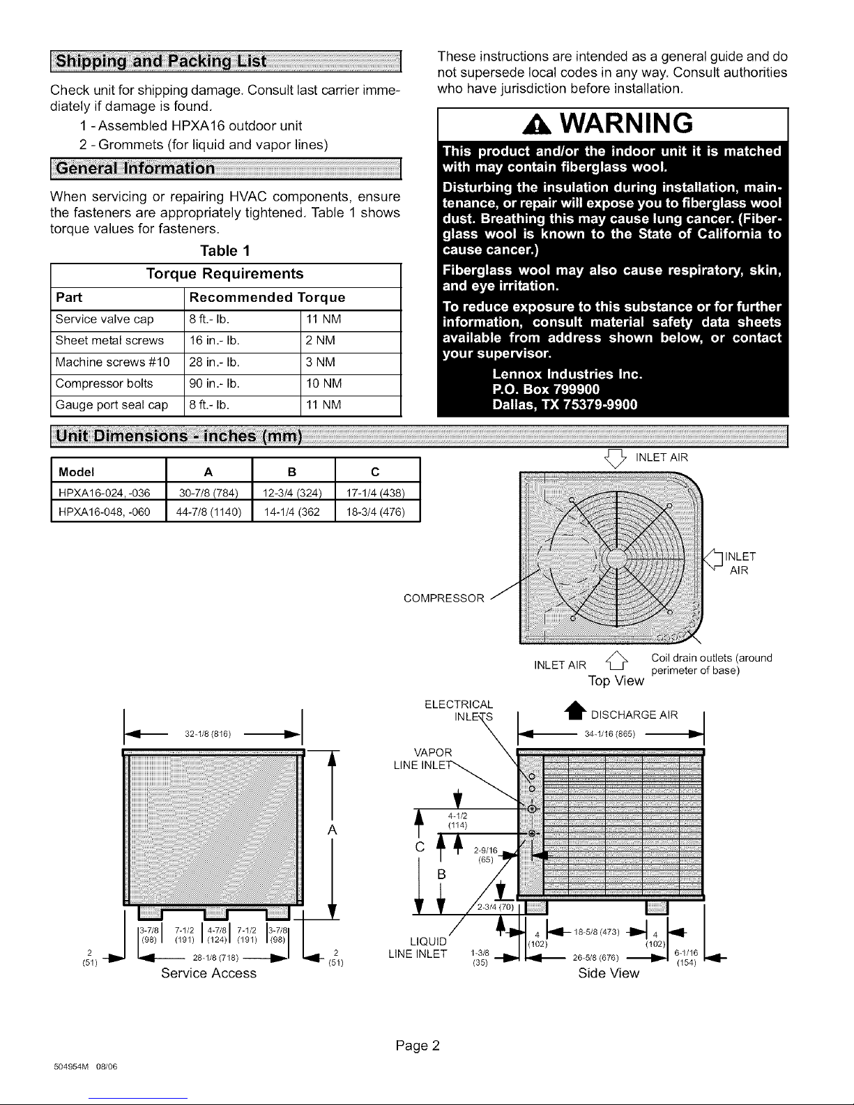
Model A B C
HPXA16-024,-036 30-7/8 (784) 12-3/4 (324) 17-1/4 (438)
HPXA16-048, -060 44-7/8 (1140) 14-1/4 (362 18-3/4 (476)
_i 32-1/8 (816) i_
i
A
COMPRESSOR j
ELECTRICAL
VAPOR
LINE INLET'-_
(114)
4-1/2
C J_ 2-_/16
B
INLET AIR
INLET AIR
O INLET
z_ Coil drain outlets (around
perimeter of base)
Top View
AIR
504954M 08/06
(51)
2
LIQUID
LINE INLET 1-3/6
(35)
Page 2
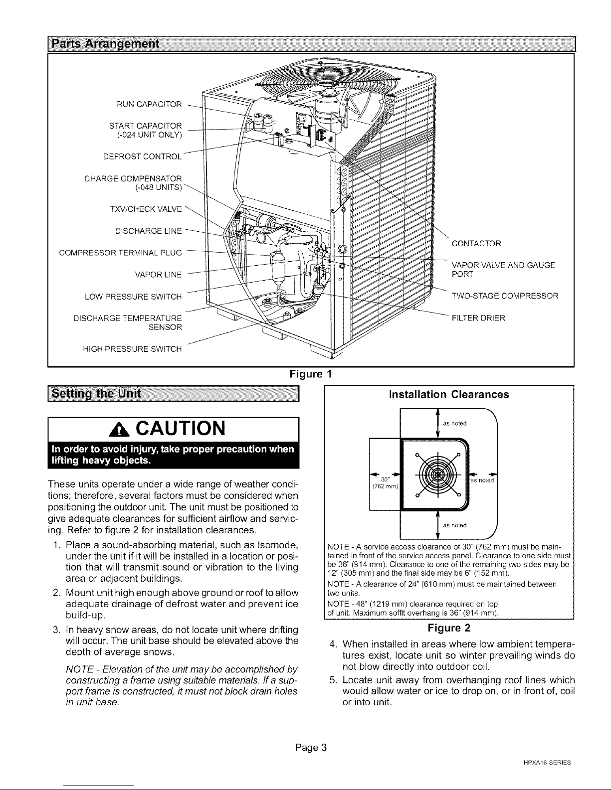
RUN CAPACITOR
START CAPACITOR
(-024 UNIT ONLY)
CHARGE COMPENSATOR
(-048 UNITS)
TXV/CHECK VALVE
DISCHARGE LINE
COMPRESSOR TERMINAL PLUG
VAPOR LINE
CONTACTOR
VAPOR VALVE AND GAUGE
PORT
LOW PRESSURE SWITCH
DISCHARGE TEMPERATURE
SENSOR
HIGH PRESSURE SWITCH
Figure 1
CAUTION
These units operate under a wide range of weather condi-
tions; therefore, several factors must be considered when
positioning the outdoor unit. The unit must be positioned to
give adequate clearances for sufficient airflow and servic-
ing. Refer to figure 2 for installation clearances.
1. Place a sound-absorbing material, such as Isomode,
under the unit if it will be installed in a location or posi-
tion that will transmit sound or vibration to the living
area or adjacent buildings.
2. Mount unit high enough above ground or roof to allow
adequate drainage of defrost water and prevent ice
build-up.
3. In heavy snow areas, do not locate unit where drifting
will occur. The unit base should be elevated above the
depth of average snows.
NOTE -Elevation of the unit may be accomplished by
constructing a frame using suitable materials. If a sup-
port frame is constructed, it must not block drain holes
in unit base.
TWO-STAGE COMPRESSOR
DRIER
Installation Clearances
as noted
(762 mm)
,,11-30" _ _} not_
l as noted J
NOTE - A service access clearance of 30" (762 mm) must be main-
tained in front of the service access panel. Clearance to one side must
be 36" (914 mm), Clearance to one of the remaining two sides may be
12" (305 mm) and the final side may be 6" (152 ram).
NOTE -A clearance of 24" (610 mm) must be maintained between
two units.
NOTE -48" (1219 mm) clearance required on top
of unit. Maximum soffit overhang is 36" (914 mm).
Figure 2
4. When installed in areas where low ambient tempera-
tures exist, locate unit so winter prevailing winds do
not blow directly into outdoor coil.
5. Locate unit away from overhanging roof lines which
would allow water or ice to drop on, or in front of, coil
or into unit.
Page 3
HPXA16 SERIES
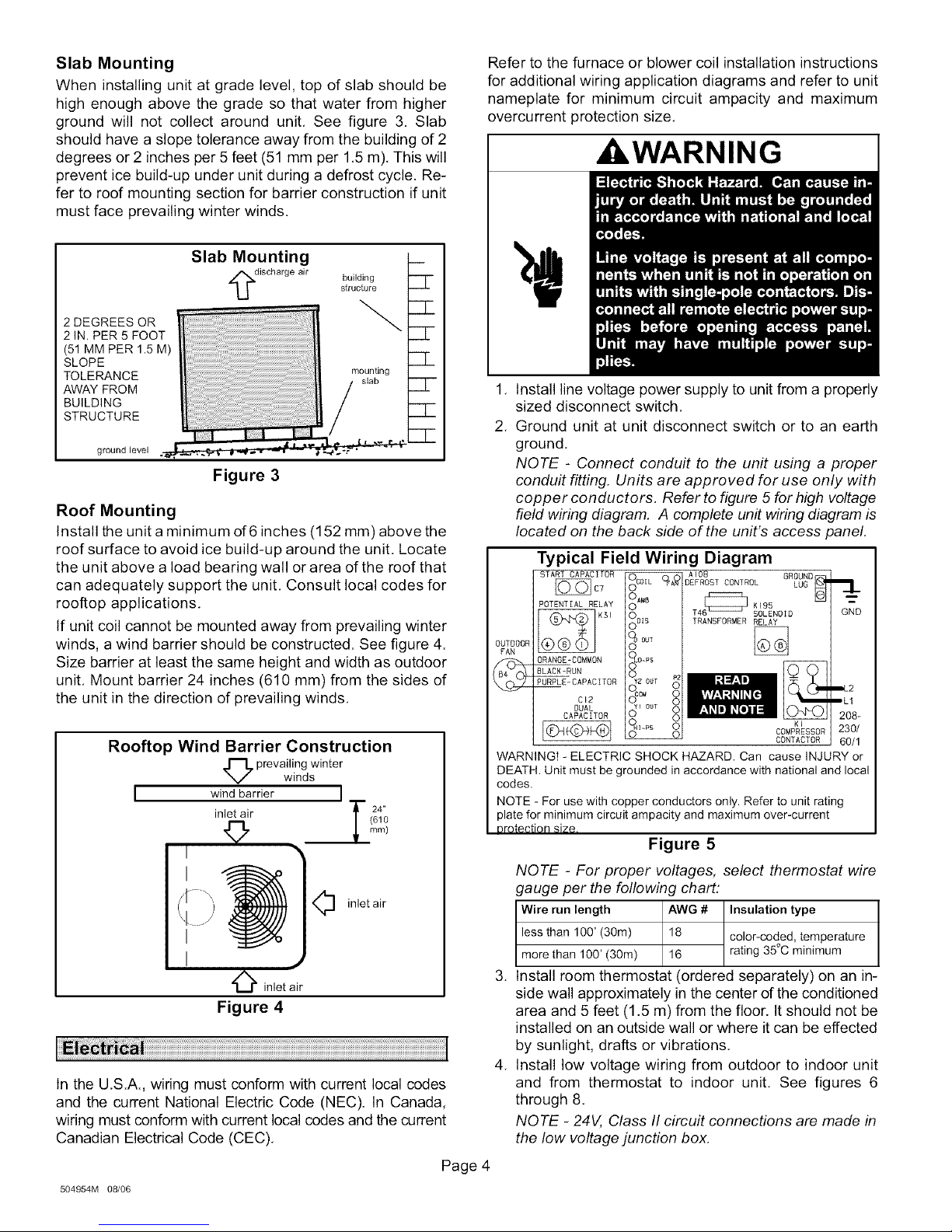
Slab Mounting
When installing unit at grade level, top of slab should be
high enough above the grade so that water from higher
ground will not collect around unit, See figure 3. Slab
should have a slope tolerance away from the building of 2
degrees or 2 inches per 5 feet (51 mm per 1,5 m), This will
prevent ice build-up under unit during a defrost cycle. Re-
fer to roof mounting section for barrier construction if unit
must face prevailing winter winds.
Slab Mounting
Refer to the furnace or blower coil installation instructions
for additional wiring application diagrams and refer to unit
nameplate for minimum circuit ampacity and maximum
overcurrent protection size.
_WARNING
discharge air building
2 DEGREES OR
2 IN. PER 5 FOOT
(51 MM PER 1.5 M)
SLOPE
TOLERANCE mounting
AWAY FROM / slab
BUILDING
STRUCTURE
ground level
structure
/
Figure 3
Roof Mounting
Install the unit a minimum of 6inches (152 mm) above the
roof surface to avoid ice build-up around the unit. Locate
the unit above a load bearing wall or area of the roof that
can adequately support the unit. Consult local codes for
rooftop applications.
If unit coil cannot be mounted away from prevailing winter
winds, a wind barrier should be constructed. See figure 4.
Size barrier at least the same height and width as outdoor
unit, Mount barrier 24 inches (610 mm) from the sides of
the unit in the direction of prevailing winds.
Rooftop Wind Barrier Construction
O prevailing winter
I wind barrier I
inlet air T (21'0
winds
© _Lmm/
I
I
O inlet air
I
I
O inlet air
Figure 4
In the U,S.A., wiring must conform with current local codes
and the current National Electric Code (NEC). In Canada,
wiring must conform with current local codes and the current
Canadian Electrical Code (CEC).
,J
.
Install line voltage power supply to unit from a properly
sized disconnect switch,
2,
Ground unit at unit disconnect switch or to an earth
ground,
NOTE - Connect conduit to the unit using a proper
conduit fitting. Units are approved for use only with
copper conductors, Refer to figure 5 for high voltage
field wiring diagram, A complete unit wiring diagram is
located on the back side of the unit's access panel.
Typical Field Wiring Diagram
START CAPACITOR AI08 GROUND
POTENTIAL RELAY 6[_ K195
OUTDOOR
FAN
ORANGE-COMMON
BLACK-RUN
PURPLE-CAPACITOR
WARNING! - ELECTRIC SHOCK HAZARD. Can cause INJURY or
DEATH. Unit must be grounded in accordance with national and local
codes.
NOTE - For use with copper conductors only. Refer to unit rating
alate for minimum circuit ampacity and maximum over-current
3rotection size
C7
KSI TRANSFORMER RELA_
C_8
DUAL
CAPACITOR
DEFROST CONTROL LUG
r_
T4 SOLENOID
GND
_2
ILl
208-
KI
COMPRESSOR 230/
CONTACTOR 60/1
Figure 5
NOTE - For proper voltages, select thermostat wire
gauge per the following chart:
Wire run length AWG # Insulation type
less than 100' (30m) 18 color-coded, temperature
more than 100' (30m) 16 rating 35°C minimum
.
Install room thermostat (ordered separately) on an in-
side wall approximately in the center d the conditioned
area and 5 feet (1.5 m) from the floor. It should not be
installed on an outside wall or where it can be effected
by sunlight, drafts or vibrations,
.
Install low voltage wiring from outdoor to indoor unit
and from thermostat to indoor unit, See figures 6
through 8.
NOTE - 24V, Class II circuit connections are made in
the low voltage junction box.
504954M 08/06
Page 4
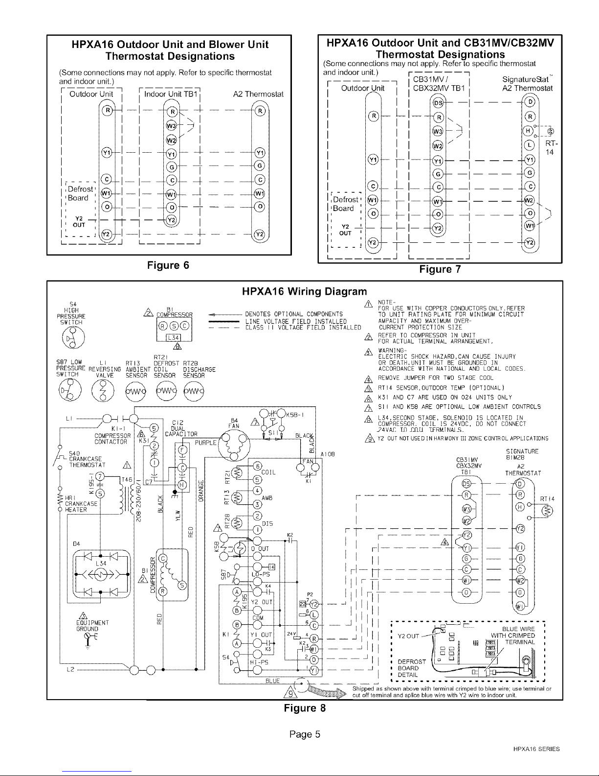
HPXA16 Outdoor Unit and Blower Unit
Thermostat Designations
(Some connections may not apply. Refer to specific thermostat
and indoor unit
Outdoor Unit
Indoor Unit TB1 I
]
A2 Thermostat
I I
I I
I I
©1
®1
',Board
,Defrost _
i
i Y2 __
:out
L.....
q--I--
-i- i--
J--i--_lI i
- --t J
Figure 6
HPXA16 Outdoor Unit and CB31MV/CB32MV
Thermostat Designations
(Some connections may not apply. Refer to specific thermostat
and indoor unit.) r i
Outdoor Unit / CBX32MV TB1 A2 Thermostat
®
_ L_I_ _..
- v- -•
©
_ LI__® I
I[Defrost,
I 'Board
I:
i Y2 i
I, OUT '
I,
i_ _ _ _ )
L
®
- +---®- -i
@
CB31MV/ I Signature_at
q
/
I I
_---
i i
I
I
If ®--i
i
I I
k I
®
(_) [ 1R4T"
@
®
@.L
@f
@
Figure 7
$4
HIGH Z_ BI
PRESSURE
SW[TCH_ _L_
$87 LDW LI RTE3 DEFROST RT28
PRESSURE REVERSING AMBIENT CDIL OISCHARGE
SWITCH VALVE SENSOR SENSOR SENSOR
COMPRESSOR
RT21
HPXA16 Wiring Diagram
--,_,--_DENOTES OPTIONAL COMPONENTS
-- -- -- CLASS II VOLTAGE FIELD INSTALLED
LINE VOLTAGE FIELD INSTALLED
z_K5B-I
BLAC_I
COIL FAN
@ KI
_ AIO8
49
_MB
@
-(z)OIS K2
LO-PS
P2
rl
s©
__YI OUT 24v
HI-PS
©
'©
NOTE-
A
FOR USE WITH COPPER CONDUCTORS ONLY.REFER
TO UNIT RATING PLATE FOR MINIMUM CIRCUIT
AMPACITY AND MAXIMUM OVER-
CURRENT PROTECTION SIZE
REFER TO COMPRESSOR IN UNIT
A
FOR ACTUAL TERMINAL ARRANGEMENT,
WARNING-
A
ELECTRIC SHOCK HAZARD,CAN CAUSE INJURY
OR DEATH,UNIT MUST BE GROUNDED IN
ACCORDANCE WITH NATIONAL AND LOCAL CODES•
REMOVE JUMPER FOR TWO STAGE COOL
A
RTi4 SENSOR,OUTDOOR TEMP IOPTIONAL)
A
K31 AND C7 ARE USED ON 024 UNITS ONLY
A
SII AND KSB ARE OPTIONAL LOW AMBIENT CONTROLS
A
L3¢,SECOND STAGE, SOLENOID IS LOCATED IN
A
COMPRESSOR, COIL IS 24VOC, DO NOT CONNECT
24VAC T_OY_IU TER_[N_.
z_Y2 OUT NOTUSEDIN HARMONYIIIZONE CON_ OL APPLICATIONS
SIGNATURE
CB31MV
CBX32MV
TBI
I
81MBB
THERMOSTAT
-- 9 IRT,A
I
I
r
I
rl
I
II
rl
FT
A
-_):>-I-
Q-I--
-4_-I- -
II
II
II
J
II
Y2 OUT _-_ -- 0 WITH CRIMPED
II
II
DEFROST o
wF
BOARD _'/'_lil
DETAIL _ _'_-_-_
, _ F" BLUE WIRE
1 °_ m _1 TERM,NAL
/I I 111
A2
®®
c_
BLUE { _ __
Z_ Shipped as shown above with terminal crimped to blue wire; use terminal or
cut off terminal and splice blue wire with Y2 wire to indoor unit.
Figure 8
Page 5
HPXA16 SERIES
If the HPXA16 unit is being installed with a new indoor coil
and line set, the refrigerant connections should be made
as outlined in this section. If an existing line set and/or in-
door coil is going to be used to complete the HPXA16 sys-
tem, refer to the following section which includes flushing
procedures.
Field refrigerant piping consists of liquid and vapor lines
from the outdoor unit (sweat connections) to the indoor coil
(flare or sweat connections). Use Lennox L15 (sweat, non-
flare) series line sets as shown in table 2 or use field-fabri-
cated refrigerant lines. Valve sizes are also listed in table 2.
Refrigerant Connections - HPXA16 Matched
with New Indoor Coil and Line Set
If an existing indoor coil which was equipped with an RFCl
metering device is being replaced, the liquid line must also
be replaced prior to the installation of the HPXA16 unit.
Table 2
Refrigerant Line Sets
Field
Mod-
el
-024
-036
-048
-060
Connections
Liquid Vapor
Line Line
3/8in. 7/8 in
(10 mm) (22 mm)
3/8 in, 1-1/8 in.
(10 mm) (29 mm)
Recommended Line Set
Liquid Vapor L15
Line Line Line Sets
3/8 in, 7/8 in L15-65
(10ram) (22ram) 15ft,-50ft,
(4.6 m - 15 m)
3/8 in, 1-1/8 in, Field
(10 ram) (29 ram) Fabricated
NOTE - Units are designed for fine sets of up to fifty feet
(15m),
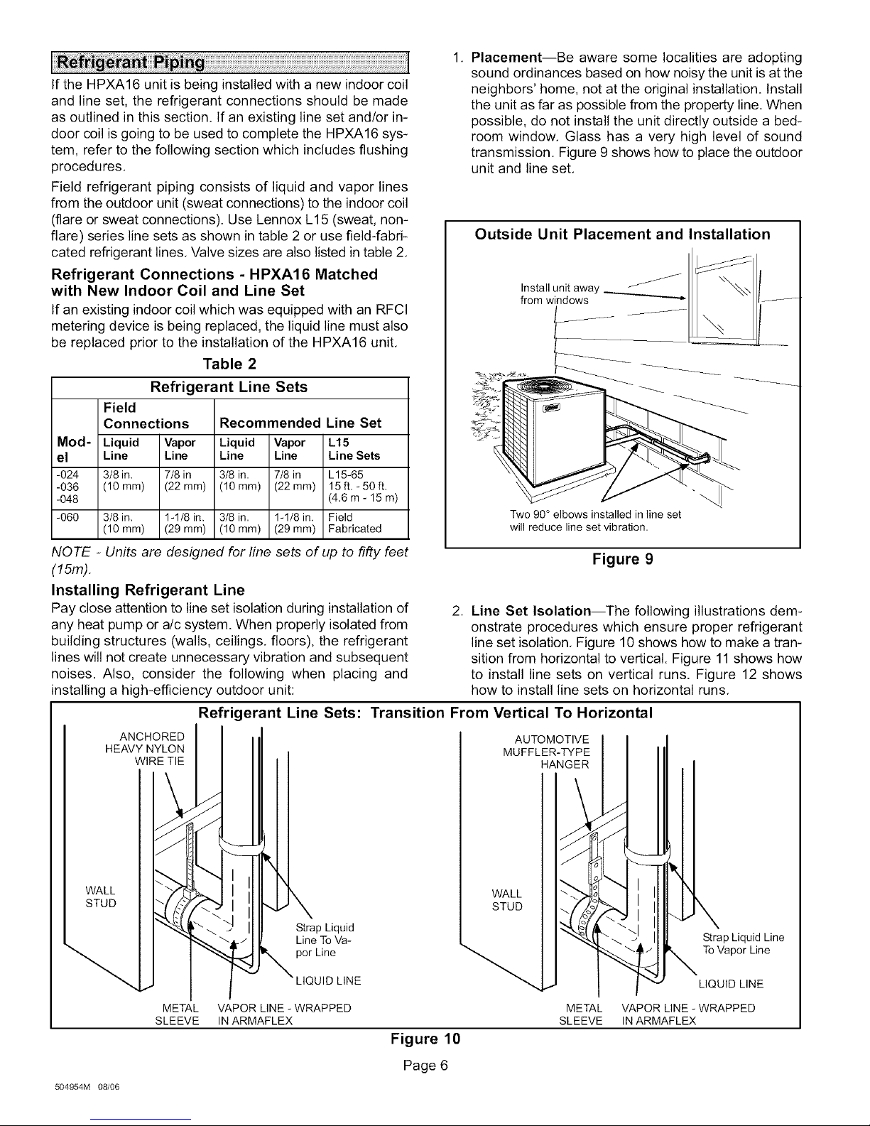
Installing Refrigerant Line
Pay close attention to line set isolation during installation of
any heat pump or a/c system. When properly isolated from
building structures (walls, ceilings, floors), the refrigerant
lines will not create unnecessary vibration and subsequent
noises. Also, consider the following when placing and
installing a high-efficiency outdoor unit:
Refrigerant Line Sets:
ANCHORED
HEAVY NYLON
WIRE TIE
Transition From Vertical To Horizontal
1, Placement--Be aware some localities are adopting
sound ordinances based on how noisy the unit is at the
neighbors' home, not at the original installation. Install
the unit as far as possible from the property line, When
possible, do not install the unit directly outside a bed-
room window, Glass has a very high level of sound
transmission, Figure 9 shows how to place the outdoor
unit and line set,
Outside Unit Placement and Installation
Two 90° elbows installed in line set
will reduce line set vibration,
Figure 9
2. Line Set Isolation--The following illustrations dem-
onstrate procedures which ensure proper refrigerant
line set isolation, Figure 10shows how to make a tran-
sition from horizontal to vertical. Figure 11 shows how
to install line sets on vertical runs. Figure 12 shows
how to install line sets on horizontal runs,
AUTOMOTIVE
MUFFLER-_PE
HANGER
WALL
STUD
METAL VAPOR LINE - WRAPPED
SLEEVE IN ARMAFLEX
504954M 08/06
Strap Liquid
Line To Va-
por Line
UID LINE
WALL
STUD
Strap Liquid Line
To Vapor Line
LIQUID LINE
METAL VAPOR LINE - WRAPPED
SLEEVE IN ARMAFLEX
Figure 10
Page 6
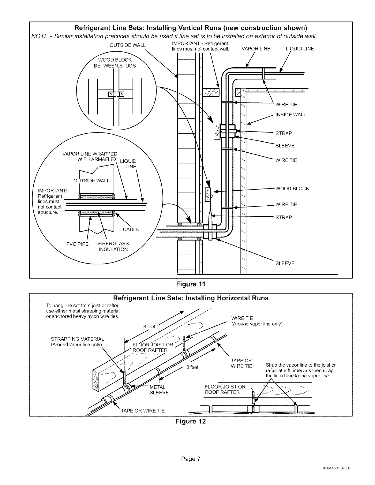
Refrigerant Line Sets: Installing Vertical Runs (new construction shown)
NOTE - Similar installation practices should be used if line set is to be installed on exterior of outside wall.
OUTSIDE WALL IMPORTANT - Refrigerant
VAPOR LINE WRAPPED
lines must not contact wall. VAPOR LINE LI UID LINE
-_. WIRE TIE
INSIDE WALL
- STRAP
SLEEVE
"_- WIRE TIE
IMPORTANT!
Refrigerant
lines must
not contact
structure.
1_ CAULK
PVC PIPE FIBERGLASS
INSULATION
Figure 11
Refrigerant Line Sets: Installing Horizontal Runs
To hang line set from joist or rafter,
use either metal strapping material
or anchored heavy nylon wire ties. WIRE TIE
8 feet (Around vapor line only)
STRAPPING MATERIAL
(Around vapor line only)
FLOOR JOIST OR
ROOF RAFTER
r\
8 feet WIRE TIE
METAL FLOOR JOIST OR .
SLEEVE ROOF RAFTER
"_ ----------WOOD BLOCK
_. _ WIRE TIE
STRAP
SLEEVE
TAPE OR
Strap the vapor line to the joist or
rafter at 8 ft. intervals then strap
the liquid line to the vapor line.
TAPE OR WIRE TIE _rl
Figure 12
Page 7
HPXA16 SERIES

Isolation Grommets
Locate the provided isolation grommets. Use a knife to slit
the webbing on each grommet. Slide larger grommet onto
vapor line and smaller grommet onto liquid line. Insert
grommets into mullion to isolate refrigerant lines from
sheet metal edges,
WARNING I
II Metering Device Installation
_ o O-RING EXPANSION VALVE &
_-_% / /O-RING (See NOTE)
@
/ ° STRA,NER
DISTRIBUTOR __ LITQuU;DLINE
NOTE - Ifnecessary,remove HCFC-22 flowcontroldevice(fixed
orifice/checkexpansionvalve)fromexistinglinesetbeforeinstalling
HFC-410A approvedexpansionvalveand o-ring.
Figure 13
Brazing Connection Procedure
1, The end of the refrigerant line must be cut square and
its internal shape must remain round. The line must be
free of nicks or dents and must be deburred (I,D, and
O.D,)
2, Before making line set connections, use dry nitrogen
to purge the refrigerant piping. This will help to prevent
oxidation and the introduction of moisture into the sys-
tem.
3, Use silver alloy brazing rods (5 or 6 percent minimum
silver alloy for copper4o-copper brazing or 45 percent
silver alloy for copper-to-brass or coppeFto-steel
brazing). Wrap a wet cloth around the valve body and
the copper tube stub. Remove light maroon washers
from service valves and shield light maroon stickers in
order to protect them during brazing, Braze the line set
to the service valve,
4, Quench the joint with water or a wet cloth to prevent
heat damage to the valve core and opening port,
NOTE - The tube end must stay bottomed in the fitting
during final assembly to ensure proper seating, seal-
ing and rigidity.
HPXA16 units may be used in check expansion valve
(CTXV) systems only, See indoor coil installation instruc-
tions and the Lennox engineering handbook for approved
HFC-410A TXV match-ups and application information,
NOTE - HFC-410A systems will not operate properly with
an HCFC-22 valve.
Check Expansion Valve Systems
Check expansion valves equipped with either Chatleff or
flare-type fittings are available from Lennox. Refer to the
Engineering Handbook forapplicable expansion valves for
use with specific match-ups.
If you install a check expansion valve with an indoor coil
that includes a fixed orifice, remove the orifice before the
check expansion valve is installed. See figure 13 for instal-
lation of the check expansion valve.
A, IMPORTANT
NOTE -If the indoor unit line and set are new, skip this sec-
tion and go on to the Manifold Gauge Set section.
_WARNING
A IMPORTANT
504954M 0_06
Page 8
 Loading...