

Lennox HPXA16-024, HPXA16-048, HPXA16 -060, HPXA16-036 Installation Instructions Manual
INSTALLATION
2006 Lennox Industries Inc.
Dallas, Texas, USA
RETAIN THESE INSTRUCTIONS
FOR FUTURE REFERENCE
WARNING
Improper installation, adjustment, alteration, service or maintenance can cause personal injury, loss
of life, or damage to property.
Installation and service must be performed by a
qualified installer or service agency.
CAUTION
Physical contact with metal edges and corners
while applying excessive force or rapid motion can
result in personal injury. Be aware of, and use
caution when working near these areas during
installation or while servicing this equipment.
IMPORTANT
This unit must be matched with an indoor coil as
specified in Lennox’ Engineering Handbook.
Coils previously charged with HCFC−22 must be
flushed.
IMPORTANT
The Clean Air Act of 1990 bans the intentional venting of refrigerant (CFC’s, HFC’s, and HCFC’s) as of
July 1, 1992. Approved methods of recovery, recycling or reclaiming must be followed. Fines and/or incarceration may be levied for noncompliance.
INSTRUCTIONS
HPXA16 Series Units
HEAT PUMP UNITS
504,954M
08/06
Supersedes 03/06
Table of Contents
HPXA16 Outdoor Unit 1. . . . . . . . . . . . . . . . . . . . . . . . . .
Shipping & Packing List 2. . . . . . . . . . . . . . . . . . . . . . . .
General Information 2. . . . . . . . . . . . . . . . . . . . . . . . . . .
Unit Dimensions 2. . . . . . . . . . . . . . . . . . . . . . . . . . . . . . .
Parts Arrangement 3. . . . . . . . . . . . . . . . . . . . . . . . . . . .
Setting the Unit 3. . . . . . . . . . . . . . . . . . . . . . . . . . . . . . .
Electrical 4. . . . . . . . . . . . . . . . . . . . . . . . . . . . . . . . . . . . .
Refrigerant Piping 6. . . . . . . . . . . . . . . . . . . . . . . . . . . . .
Refrigerant Metering Device 8. . . . . . . . . . . . . . . . . . . .
Flushing Existing Line Set & Indoor Coil 8. . . . . . . . . .
Manifold Gauge Set 10. . . . . . . . . . . . . . . . . . . . . . . . . . .
Service Valves 10. . . . . . . . . . . . . . . . . . . . . . . . . . . . . . . .
Leak Testing 11. . . . . . . . . . . . . . . . . . . . . . . . . . . . . . . . . .
Evacuation 12. . . . . . . . . . . . . . . . . . . . . . . . . . . . . . . . . . .
Start−Up 12. . . . . . . . . . . . . . . . . . . . . . . . . . . . . . . . . . . . . .
Refrigerant Charging 12. . . . . . . . . . . . . . . . . . . . . . . . . .
System Operation 15. . . . . . . . . . . . . . . . . . . . . . . . . . . . .
Defrost System 16. . . . . . . . . . . . . . . . . . . . . . . . . . . . . . .
Maintenance 21. . . . . . . . . . . . . . . . . . . . . . . . . . . . . . . . . .
Optional Accessories 21. . . . . . . . . . . . . . . . . . . . . . . . . .
Check Points 22. . . . . . . . . . . . . . . . . . . . . . . . . . . . . . . . .
Homeowner Information:
Maintenance 23. . . . . . . . . . . . . . . . . . . . . . . . . . . . . . . . . .
Thermostat Operation 24. . . . . . . . . . . . . . . . . . . . . . . . . .
HPXA16 Outdoor Unit
Lennox HPXA16 outdoor units use HFC−410A refrigerant.
This unit must be installed with a matching indoor coil and
line set as outlined in the Lennox Engineering Handbook.
Elite® Series HPXA16 outdoor units are designed for use
in check expansion valve (CTXV) systems only and must
not be used with other refrigerant flow control devices.
See Lennox Engineering Handbook list of indoor expansion valve kits (ordered separately).
Litho U.S.A.
08/06 504,954M
*2P0806* *P504954M*
Page 1
Shipping and Packing List
Check unit for shipping damage. Consult last carrier immediately if damage is found.
1 − Assembled HPXA16 outdoor unit
2 − Grommets (for liquid and vapor lines)
General Information
When servicing or repairing HVAC components, ensure
the fasteners are appropriately tightened. Table 1 shows
torque values for fasteners.
Table 1
Torque Requirements
Part Recommended Torque
Service valve cap 8 ft.− lb. 11 NM
Sheet metal screws 16 in.− lb. 2 NM
Machine screws #10 28 in.− lb. 3 NM
Compressor bolts 90 in.− lb. 10 NM
Gauge port seal cap 8 ft.− lb. 11 NM
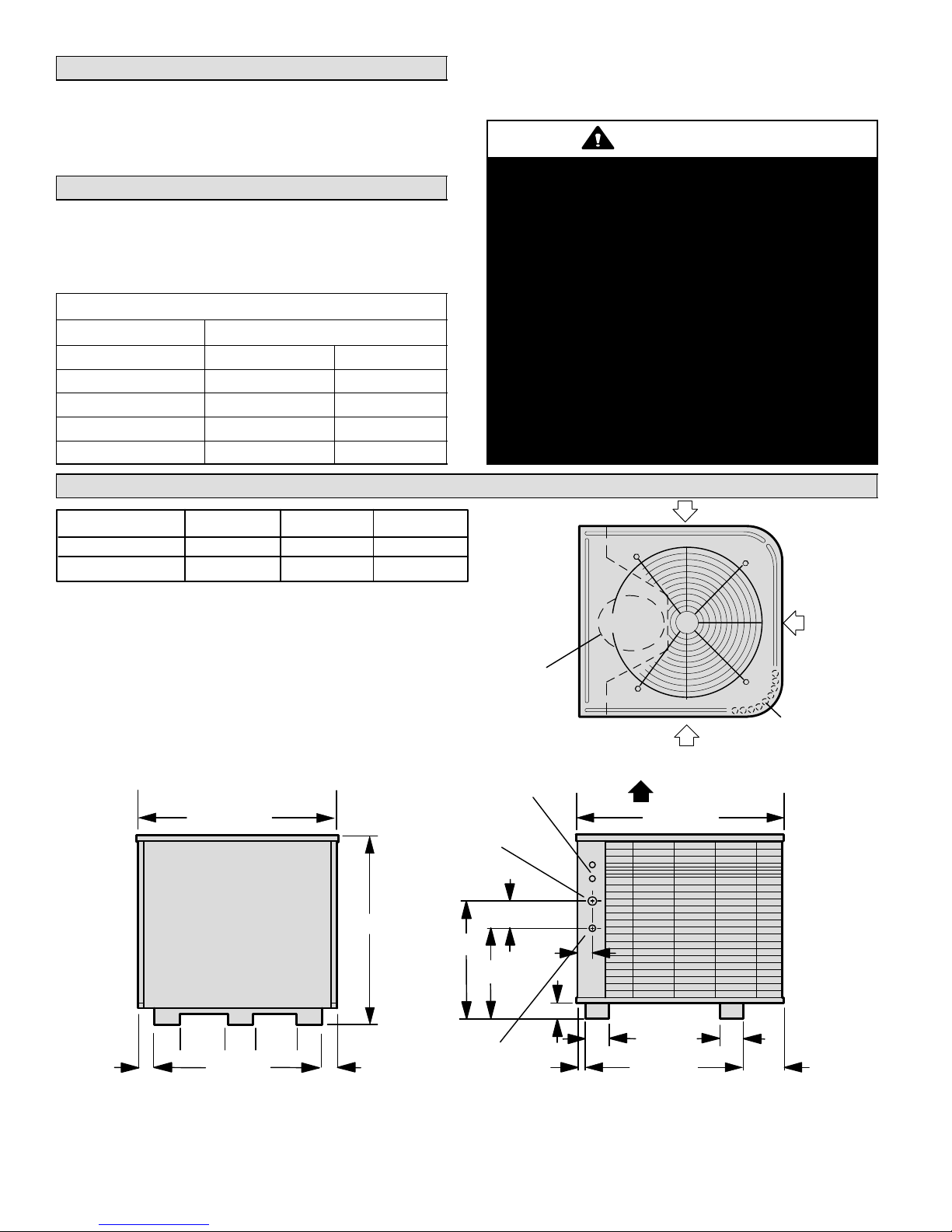
Unit Dimensions − inches (mm)
Model A B C
HPXA16−024, −036 30-7/8 (784) 12-3/4 (324) 17-1/4 (438)
HPXA16−048, −060 44-7/8 (1140) 14-1/4 (362 18-3/4 (476)
These instructions are intended as a general guide and do
not supersede local codes in any way. Consult authorities
who have jurisdiction before installation.
WARNING
This product and/or the indoor unit it is matched
with may contain fiberglass wool.
Disturbing the insulation during installation, maintenance, or repair will expose you to fiberglass wool
dust. Breathing this may cause lung cancer. (Fiberglass wool is known to the State of California to
cause cancer.)
Fiberglass wool may also cause respiratory, skin,
and eye irritation.
To reduce exposure to this substance or for further
information, consult material safety data sheets
available from address shown below, or contact
your supervisor.
Lennox Industries Inc.
P.O. Box 799900
Dallas, TX 75379−9900
INLET AIR
(51)
INLET
AIR
COMPRESSOR
INLET AIR
Coil drain outlets (around
perimeter of base)
Top View
ELECTRICAL
INLETS
32-1/8 (816) 34-1/16 (865)
VAPOR
LINE INLET
4-1/2
A
(114)
C
2-9/16
(65)
DISCHARGE AIR
B
2-3/4 (70)
4-7/8
(124)
7−1/2
(191)
3-7/8
(98)
(51)
18-5/8 (473)
2
LIQUID
LINE INLET
1-3/8
(35)
4
(102)
26−5/8 (676)
4
(102)
6-1/16
(154)
7−1/2
3-7/8
(191)
2
(98)
28-1/8 (718)
Side ViewService Access
504954M 08/06
Page 2
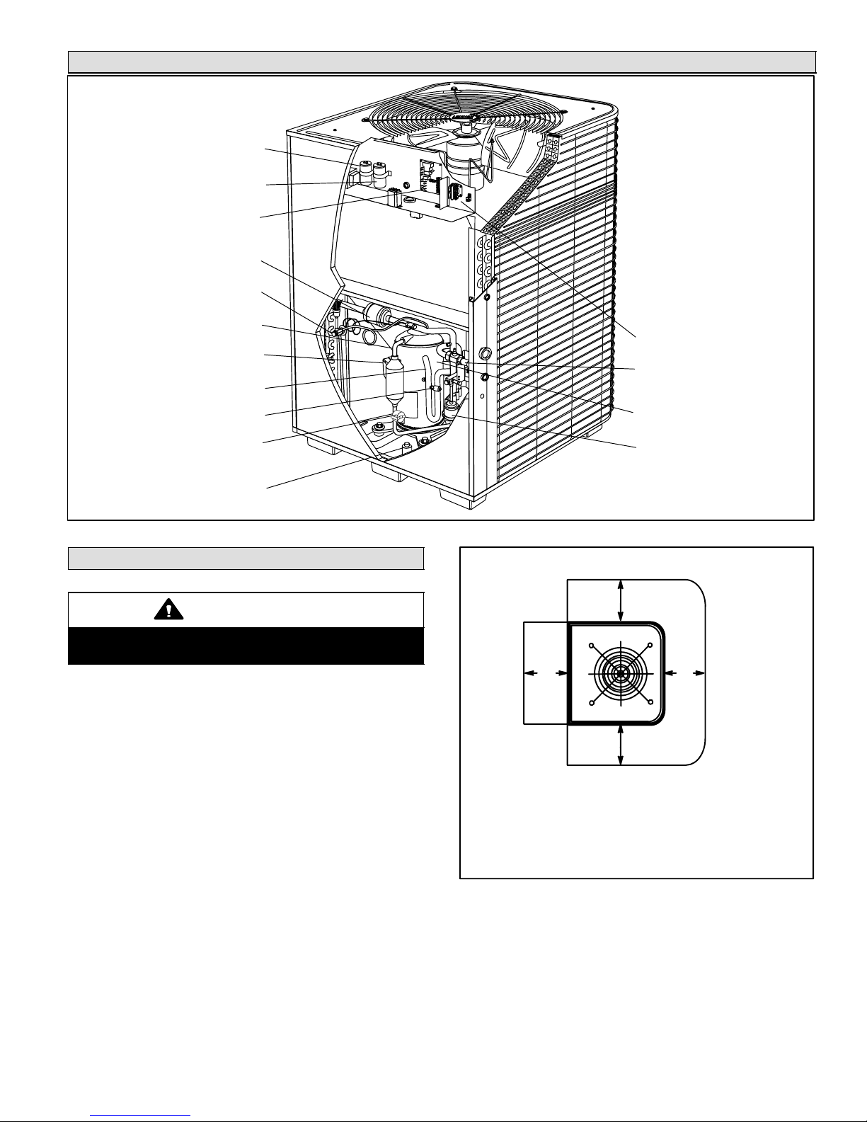
Parts Arrangement
RUN CAPACITOR
START CAPACITOR
(−024 UNIT ONLY)
DEFROST CONTROL
CHARGE COMPENSATOR
(−048 UNITS)
TXV/CHECK VALVE
DISCHARGE LINE
COMPRESSOR TERMINAL PLUG
VAPOR LINE
LOW PRESSURE SWITCH
DISCHARGE TEMPERATURE
SENSOR
HIGH PRESSURE SWITCH
Setting the Unit
CAUTION
In order to avoid injury, take proper precaution when
lifting heavy objects.
CONTACTOR
VAPOR VALVE AND GAUGE
PORT
TWO−STAGE COMPRESSOR
FILTER DRIER
Figure 1
Installation Clearances
as noted
These units operate under a wide range of weather conditions; therefore, several factors must be considered when
positioning the outdoor unit. The unit must be positioned to
give adequate clearances for sufficient airflow and servicing. Refer to figure 2 for installation clearances.
1. Place a sound−absorbing material, such as Isomode,
under the unit if it will be installed in a location or position that will transmit sound or vibration to the living
area or adjacent buildings.
2. Mount unit high enough above ground or roof to allow
adequate drainage of defrost water and prevent ice
build−up.
3. In heavy snow areas, do not locate unit where drifting
will occur. The unit base should be elevated above the
depth of average snows.
NOTE − Elevation of the unit may be accomplished by
constructing a frame using suitable materials. If a support frame is constructed, it must not block drain holes
in unit base.
Page 3
30"
(762 mm)
NOTE − A service access clearance of 30" (762 mm) must be maintained in front of the service access panel. Clearance to one side must
be 36" (914 mm). Clearance to one of the remaining two sides may be
12" (305 mm) and the final side may be 6" (152 mm).
NOTE − A clearance of 24" (610 mm) must be maintained between
two units.
NOTE − 48" (1219 mm) clearance required on top
of unit. Maximum soffit overhang is 36" (914 mm).
as noted
as noted
Figure 2
4. When installed in areas where low ambient temperatures exist, locate unit so winter prevailing winds do
not blow directly into outdoor coil.
5. Locate unit away from overhanging roof lines which
would allow water or ice to drop on, or in front of, coil
or into unit.
HPXA16 SERIES
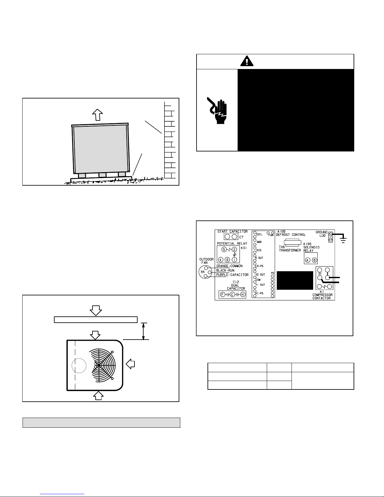
Slab Mounting
color coded, temperature
When installing unit at grade level, top of slab should be
high enough above the grade so that water from higher
ground will not collect around unit. See figure 3. Slab
should have a slope tolerance away from the building of 2
degrees or 2 inches per 5 feet (51 mm per 1.5 m). This will
prevent ice build−up under unit during a defrost cycle. Refer to roof mounting section for barrier construction if unit
must face prevailing winter winds.
Slab Mounting
discharge air
2 DEGREES OR
2 IN. PER 5 FOOT
(51 MM PER 1.5 M)
SLOPE
TOLERANCE
AWAY FROM
BUILDING
STRUCTURE
ground level
building
structure
mounting
slab
Figure 3
Roof Mounting
Install the unit a minimum of 6 inches (152 mm) above the
roof surface to avoid ice build−up around the unit. Locate
the unit above a load bearing wall or area of the roof that
can adequately support the unit. Consult local codes for
rooftop applications.
If unit coil cannot be mounted away from prevailing winter
winds, a wind barrier should be constructed. See figure 4.
Size barrier at least the same height and width as outdoor
unit. Mount barrier 24 inches (610 mm) from the sides of
the unit in the direction of prevailing winds.
Rooftop Wind Barrier Construction
prevailing winter
winds
wind barrier
inlet air
inlet air
24"
(610
mm)
inlet air
Figure 4
Electrical
In the U.S.A., wiring must conform with current local codes
and the current National Electric Code (NEC). In Canada,
wiring must conform with current local codes and the current
Canadian Electrical Code (CEC).
Refer to the furnace or blower coil installation instructions
for additional wiring application diagrams and refer to unit
nameplate for minimum circuit ampacity and maximum
overcurrent protection size.
WARNING
Electric Shock Hazard. Can cause injury or death. Unit must be grounded
in accordance with national and local
codes.
Line voltage is present at all components when unit is not in operation on
units with single-pole contactors. Disconnect all remote electric power supplies before opening access panel.
Unit may have multiple power supplies.
1. Install line voltage power supply to unit from a properly
sized disconnect switch.
2. Ground unit at unit disconnect switch or to an earth
ground.
NOTE − Connect conduit to the unit using a proper
conduit fitting. Units are approved for use only with
copper conductors. Refer to figure 5 for high voltage
field wiring diagram. A complete unit wiring diagram is
located on the back side of the unit’s access panel.
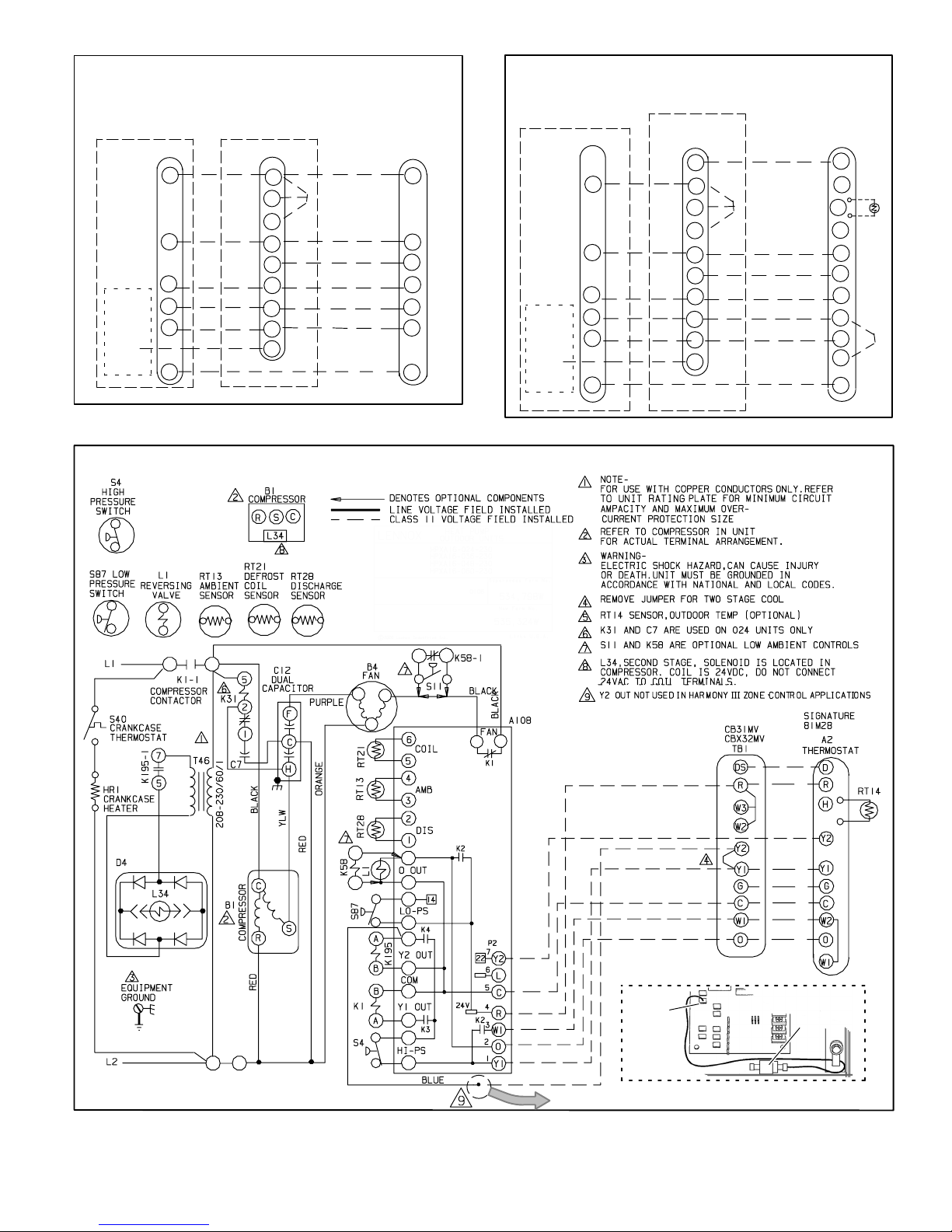
Typical Field Wiring Diagram
GND
READ
WARNING
AND NOTE
WARNING! − ELECTRIC SHOCK HAZARD. Can cause INJURY or
DEATH. Unit must be grounded in accordance with national and local
codes.
NOTE − For use with copper conductors only. Refer to unit rating
plate for minimum circuit ampacity and maximum over-current
protection size.
Figure 5
NOTE − For proper voltages, select thermostat wire
gauge per the following chart:
Wire run length AWG # Insulation type
less than 100’ (30m) 18
more than 100’ (30m) 16
3. Install room thermostat (ordered separately) on an inside wall approximately in the center of the conditioned
area and 5 feet (1.5 m) from the floor. It should not be
installed on an outside wall or where it can be effected
by sunlight, drafts or vibrations.
4. Install low voltage wiring from outdoor to indoor unit
and from thermostat to indoor unit. See figures 6
through 8.
NOTE − 24V, Class II circuit connections are made in
the low voltage junction box.
color−coded, temperature
rating 35ºC minimum
L2
L1
208−
230/
60/1
504954M 08/06
Page 4
HPXA16 Outdoor Unit and Blower Unit
Thermostat Designations
(Some connections may not apply. Refer to specific thermostat
and indoor unit.)
Outdoor Unit Indoor Unit TB1
Defrost
Board
Y2
OUT
R
Y1
C
W1
O
Y2
R
W3
W2
Y1
G
C
W1
O
Y2
A2 Thermostat
R
Y1
G
C
W1
O
Y2
HPXA16 Outdoor Unit and CB31MV/CB32MV
Thermostat Designations
(Some connections may not apply. Refer to specific thermostat
and indoor unit.)
Outdoor Unit
Defrost
W1
Board
Y2
OUT
Y2
R
Y1
C
O
CB31MV /
CBX32MV TB1
DS
R
W3
W2
Y1
G
C
W1
O
Y2
SignatureStat
A2 Thermostat
D
R
H
L
Y1
G
C
W2
O
W1
Y2
RT−
14
Figure 6
Figure 7
HPXA16 Wiring Diagram
Figure 8
Page 5
BLUE WIRE
Y2 OUT
DEFROST
BOARD
DETAIL
Shipped as shown above with terminal crimped to blue wire; use terminal or
cut off terminal and splice blue wire with Y2 wire to indoor unit.
WITH CRIMPED
TERMINAL
HPXA16 SERIES
Refrigerant Piping
If the HPXA16 unit is being installed with a new indoor coil
and line set, the refrigerant connections should be made
as outlined in this section. If an existing line set and/or indoor coil is going to be used to complete the HPXA16 system, refer to the following section which includes flushing
procedures.
Field refrigerant piping consists of liquid and vapor lines
from the outdoor unit (sweat connections) to the indoor coil
(flare or sweat connections). Use Lennox L15 (sweat, nonflare) series line sets as shown in table 2 or use field-fabricated refrigerant lines. Valve sizes are also listed in table 2.
Refrigerant Connections − HPXA16 Matched
with New Indoor Coil and Line Set
If an existing indoor coil which was equipped with an RFCI
metering device is being replaced, the liquid line must also
be replaced prior to the installation of the HPXA16 unit.
Table 2
Refrigerant Line Sets
Field
Connections
Model
−024
−036
−048
−060 3/8 in.
Liquid
Line
3/8 in.
(10 mm)
(10 mm)
Vapor
Line
7/8 in
(22 mm)
1−1/8 in.
(29 mm)
Recommended Line Set
Liquid
Line
3/8 in.
(10 mm)
3/8 in.
(10 mm)
Vapor
Line
7/8 in
(22 mm)
1−1/8 in.
(29 mm)
L15
Line Sets
L15−65
15 ft. − 50 ft.
(4.6 m − 15 m)
Field
Fabricated
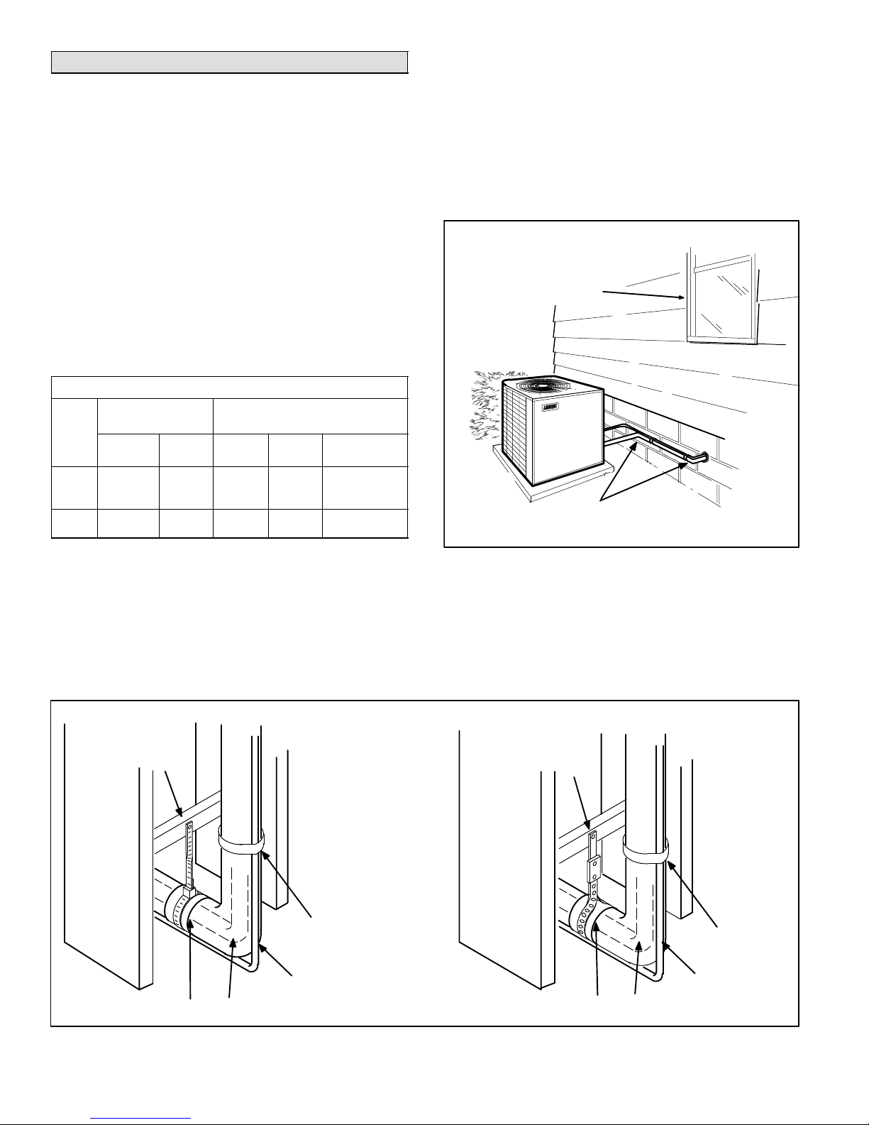
1. PlacementBe aware some localities are adopting
sound ordinances based on how noisy the unit is at the
neighbors’ home, not at the original installation. Install
the unit as far as possible from the property line. When
possible, do not install the unit directly outside a bedroom window. Glass has a very high level of sound
transmission. Figure 9 shows how to place the outdoor
unit and line set.
Outside Unit Placement and Installation
Install unit away
from windows
Two 90° elbows installed in line set
will reduce line set vibration.
NOTE − Units are designed for line sets of up to fifty feet
(15m).
Installing Refrigerant Line
Pay close attention to line set isolation during installation of
any heat pump or a/c system. When properly isolated from
building structures (walls, ceilings. floors), the refrigerant
lines will not create unnecessary vibration and subsequent
noises. Also, consider the following when placing and
installing a high−efficiency outdoor unit:
Refrigerant Line Sets: Transition From Vertical To Horizontal
ANCHORED
HEAVY NYLON
WIRE TIE
WALL
STUD
Strap Liquid
Line To Vapor Line
Figure 9
2. Line Set IsolationThe following illustrations demonstrate procedures which ensure proper refrigerant
line set isolation. Figure 10 shows how to make a transition from horizontal to vertical. Figure 11 shows how
to install line sets on vertical runs. Figure 12 shows
how to install line sets on horizontal runs.
AUTOMOTIVE
MUFFLER-TYPE
HANGER
WALL
STUD
Strap Liquid Line
To Vapor Line
METAL
SLEEVE
504954M 08/06
VAPOR LINE − WRAPPED
IN ARMAFLEX
LIQUID LINE
Figure 10
Page 6
METAL
SLEEVE
LIQUID LINE
VAPOR LINE − WRAPPED
IN ARMAFLEX
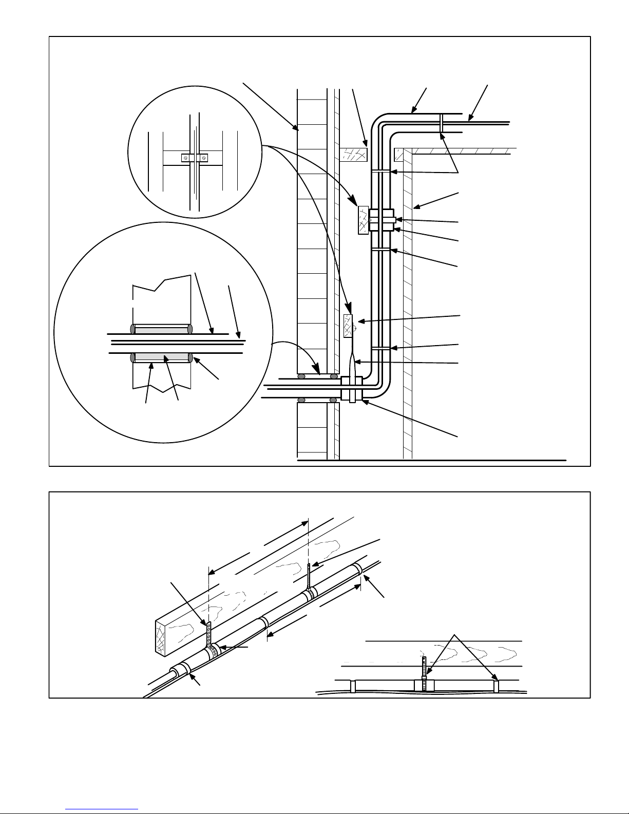
Refrigerant Line Sets: Installing Vertical Runs (new construction shown)
NOTE − Similar installation practices should be used if line set is to be installed on exterior of outside wall.
IMPORTANT - Refrigerant
lines must not contact wall.
LIQUID LINEVAPOR LINE
WIRE TIE
INSIDE WALL
STRAP
SLEEVE
WIRE TIE
WOOD BLOCK
WIRE TIE
STRAP
VAPOR LINE WRAPPED
IMPORTANT!
Refrigerant
lines must
not contact
structure.
WOOD BLOCK
BETWEEN STUDS
WITH ARMAFLEX
OUTSIDE WALL
OUTSIDE WALL
LIQUID
LINE
PVC PIPE
FIBERGLASS
INSULATION
Refrigerant Line Sets: Installing Horizontal Runs
To hang line set from joist or rafter,
use either metal strapping material
or anchored heavy nylon wire ties.
STRAPPING MATERIAL
(Around vapor line only)
CAULK
8 feet
FLOOR JOIST OR
ROOF RAFTER
METAL
SLEEVE
Figure 11
8 feet
WIRE TIE
(Around vapor line only)
TAPE OR
WIRE TIE
FLOOR JOIST OR
ROOF RAFTER
SLEEVE
Strap the vapor line to the joist or
rafter at 8 ft. intervals then strap
the liquid line to the vapor line.
TAPE OR WIRE TIE
Figure 12
Page 7
HPXA16 SERIES
Isolation Grommets
Locate the provided isolation grommets. Use a knife to slit
the webbing on each grommet. Slide larger grommet onto
vapor line and smaller grommet onto liquid line. Insert
grommets into mullion to isolate refrigerant lines from
sheet metal edges.
WARNING
Polyol ester (POE) oils used with HFC−410A refrigerant absorb moisture very quickly. It is very important that the refrigerant system be kept closed
as much as possible. DO NOT remove line set caps
or service valve stub caps until you are ready to
make connections.
Brazing Connection Procedure
1. The end of the refrigerant line must be cut square and
its internal shape must remain round. The line must be
free of nicks or dents and must be deburred (I.D. and
O.D.)
2. Before making line set connections, use dry nitrogen
to purge the refrigerant piping. This will help to prevent
oxidation and the introduction of moisture into the system.
3. Use silver alloy brazing rods (5 or 6 percent minimum
silver alloy for copper−to−copper brazing or 45 percent
silver alloy for copper−to−brass or copper−to−steel
brazing). Wrap a wet cloth around the valve body and
the copper tube stub. Remove light maroon washers
from service valves and shield light maroon stickers in
order to protect them during brazing. Braze the line set
to the service valve.
4. Quench the joint with water or a wet cloth to prevent
heat damage to the valve core and opening port.
NOTE − The tube end must stay bottomed in the fitting
during final assembly to ensure proper seating, sealing and rigidity.
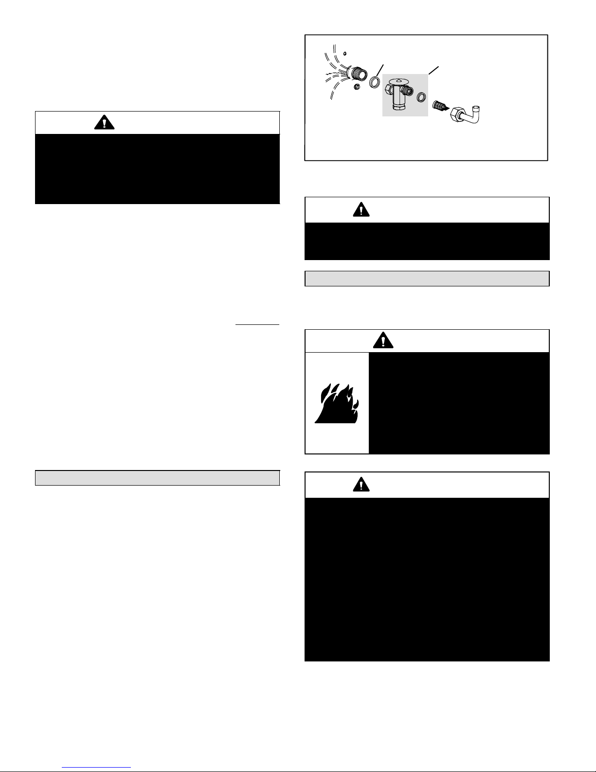
Metering Device Installation
O−RING
DISTRIBUTOR
NOTE − If necessary, remove HCFC−22 flow control device (fixed
orifice/check expansion valve) from existing line set before installing
HFC−410A approved expansion valve and o−ring.
EXPANSION VALVE &
O−RING (See NOTE)
STRAINER
LIQUID LINE
STUB
Figure 13
IMPORTANT
Failure to remove a fixed orifice when installing an
expansion valve on the indoor coil will result in improper operation and damage to the system.
Flushing Existing Line Set & Indoor Coil
NOTE − If the indoor unit line and set are new, skip this section and go on to the Manifold Gauge Set section.
WARNING
Danger of fire. Bleeding the refrigerant charge from only the high side
may result in the low side shell and
suction tubing being pressurized. Application of a brazing torch while
pressurized may result in ignition of
the refrigerant and oil mixture − check
the high and low pressures before unbrazing.
Refrigerant Metering Device
HPXA16 units may be used in check expansion valve
(CTXV) systems only. See indoor coil installation instructions and the Lennox engineering handbook for approved
HFC−410A TXV match−ups and application information.
NOTE − HFC−410A systems will not operate properly with
an HCFC−22 valve.
Check Expansion Valve Systems
Check expansion valves equipped with either Chatleff or
flare−type fittings are available from Lennox. Refer to the
Engineering Handbook for applicable expansion valves for
use with specific match-ups.
If you install a check expansion valve with an indoor coil
that includes a fixed orifice, remove the orifice before the
check expansion valve is installed. See figure 13 for installation of the check expansion valve.
504954M 08/06
IMPORTANT
If this unit is being matched with an approved line
set or indoor coil which was previously charged
with HCFC−22 refrigerant, or if it is being matched
with a coil which was manufactured before January of 1999, the coil and line set must be flushed
prior to installation. Take care to empty all existing
traps.
Polyol ester (POE) oils are used in Lennox units
charged with HFC−410A refrigerant. Residual mineral oil can act as an insulator, preventing proper
heat transfer. It can also clog the check expansion
valve, reducing system performance and capacity.
Failure to properly flush the system per the instructions below will void the warranty.
Page 8
 Loading...