

Page 1
INSTALLATION
2006 Lennox Industries Inc.
Dallas, Texas, USA
RETAIN THESE INSTRUCTIONS
FOR FUTURE REFERENCE
WARNING
Improper installation, adjustment, alteration, service or maintenance can cause personal injury, loss
of life, or damage to property.
Installation and service must be performed by a
qualified installer or service agency.
CAUTION
Physical contact with metal edges and corners
while applying excessive force or rapid motion can
result in personal injury. Be aware of, and use
caution when working near these areas during
installation or while servicing this equipment.
IMPORTANT
This unit must be matched with an indoor coil as
specified in Lennox’ Engineering Handbook.
Coils previously charged with HCFC−22 must be
flushed.
IMPORTANT
The Clean Air Act of 1990 bans the intentional venting of refrigerant (CFC’s, HFC’s, and HCFC’s) as of
July 1, 1992. Approved methods of recovery, recycling or reclaiming must be followed. Fines and/or incarceration may be levied for noncompliance.
INSTRUCTIONS
HPXA16 Series Units
HEAT PUMP UNITS
504,954M
08/06
Supersedes 03/06
Table of Contents
HPXA16 Outdoor Unit 1. . . . . . . . . . . . . . . . . . . . . . . . . .
Shipping & Packing List 2. . . . . . . . . . . . . . . . . . . . . . . .
General Information 2. . . . . . . . . . . . . . . . . . . . . . . . . . .
Unit Dimensions 2. . . . . . . . . . . . . . . . . . . . . . . . . . . . . . .
Parts Arrangement 3. . . . . . . . . . . . . . . . . . . . . . . . . . . .
Setting the Unit 3. . . . . . . . . . . . . . . . . . . . . . . . . . . . . . .
Electrical 4. . . . . . . . . . . . . . . . . . . . . . . . . . . . . . . . . . . . .
Refrigerant Piping 6. . . . . . . . . . . . . . . . . . . . . . . . . . . . .
Refrigerant Metering Device 8. . . . . . . . . . . . . . . . . . . .
Flushing Existing Line Set & Indoor Coil 8. . . . . . . . . .
Manifold Gauge Set 10. . . . . . . . . . . . . . . . . . . . . . . . . . .
Service Valves 10. . . . . . . . . . . . . . . . . . . . . . . . . . . . . . . .
Leak Testing 11. . . . . . . . . . . . . . . . . . . . . . . . . . . . . . . . . .
Evacuation 12. . . . . . . . . . . . . . . . . . . . . . . . . . . . . . . . . . .
Start−Up 12. . . . . . . . . . . . . . . . . . . . . . . . . . . . . . . . . . . . . .
Refrigerant Charging 12. . . . . . . . . . . . . . . . . . . . . . . . . .
System Operation 15. . . . . . . . . . . . . . . . . . . . . . . . . . . . .
Defrost System 16. . . . . . . . . . . . . . . . . . . . . . . . . . . . . . .
Maintenance 21. . . . . . . . . . . . . . . . . . . . . . . . . . . . . . . . . .
Optional Accessories 21. . . . . . . . . . . . . . . . . . . . . . . . . .
Check Points 22. . . . . . . . . . . . . . . . . . . . . . . . . . . . . . . . .
Homeowner Information:
Maintenance 23. . . . . . . . . . . . . . . . . . . . . . . . . . . . . . . . . .
Thermostat Operation 24. . . . . . . . . . . . . . . . . . . . . . . . . .
HPXA16 Outdoor Unit
Lennox HPXA16 outdoor units use HFC−410A refrigerant.
This unit must be installed with a matching indoor coil and
line set as outlined in the Lennox Engineering Handbook.
Elite® Series HPXA16 outdoor units are designed for use
in check expansion valve (CTXV) systems only and must
not be used with other refrigerant flow control devices.
See Lennox Engineering Handbook list of indoor expansion valve kits (ordered separately).
Litho U.S.A.
08/06 504,954M
*2P0806* *P504954M*
Page 1
Page 2
Shipping and Packing List
Check unit for shipping damage. Consult last carrier immediately if damage is found.
1 − Assembled HPXA16 outdoor unit
2 − Grommets (for liquid and vapor lines)
General Information
When servicing or repairing HVAC components, ensure
the fasteners are appropriately tightened. Table 1 shows
torque values for fasteners.
Table 1
Torque Requirements
Part Recommended Torque
Service valve cap 8 ft.− lb. 11 NM
Sheet metal screws 16 in.− lb. 2 NM
Machine screws #10 28 in.− lb. 3 NM
Compressor bolts 90 in.− lb. 10 NM
Gauge port seal cap 8 ft.− lb. 11 NM
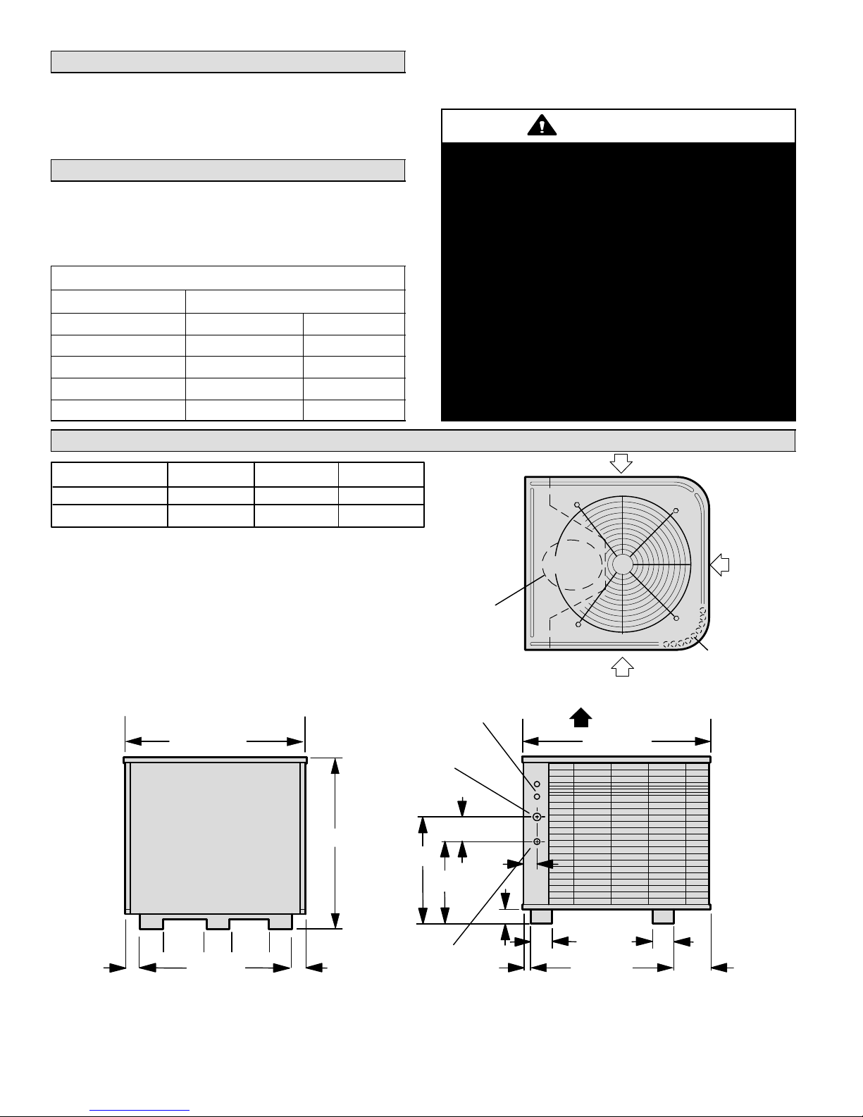
Unit Dimensions − inches (mm)
Model A B C
HPXA16−024, −036 30-7/8 (784) 12-3/4 (324) 17-1/4 (438)
HPXA16−048, −060 44-7/8 (1140) 14-1/4 (362 18-3/4 (476)
These instructions are intended as a general guide and do
not supersede local codes in any way. Consult authorities
who have jurisdiction before installation.
WARNING
This product and/or the indoor unit it is matched
with may contain fiberglass wool.
Disturbing the insulation during installation, maintenance, or repair will expose you to fiberglass wool
dust. Breathing this may cause lung cancer. (Fiberglass wool is known to the State of California to
cause cancer.)
Fiberglass wool may also cause respiratory, skin,
and eye irritation.
To reduce exposure to this substance or for further
information, consult material safety data sheets
available from address shown below, or contact
your supervisor.
Lennox Industries Inc.
P.O. Box 799900
Dallas, TX 75379−9900
INLET AIR
(51)
INLET
AIR
COMPRESSOR
INLET AIR
Coil drain outlets (around
perimeter of base)
Top View
ELECTRICAL
INLETS
32-1/8 (816) 34-1/16 (865)
VAPOR
LINE INLET
4-1/2
A
(114)
C
2-9/16
(65)
DISCHARGE AIR
B
2-3/4 (70)
4-7/8
(124)
7−1/2
(191)
3-7/8
(98)
(51)
18-5/8 (473)
2
LIQUID
LINE INLET
1-3/8
(35)
4
(102)
26−5/8 (676)
4
(102)
6-1/16
(154)
7−1/2
3-7/8
(191)
2
(98)
28-1/8 (718)
Side ViewService Access
504954M 08/06
Page 2
Page 3
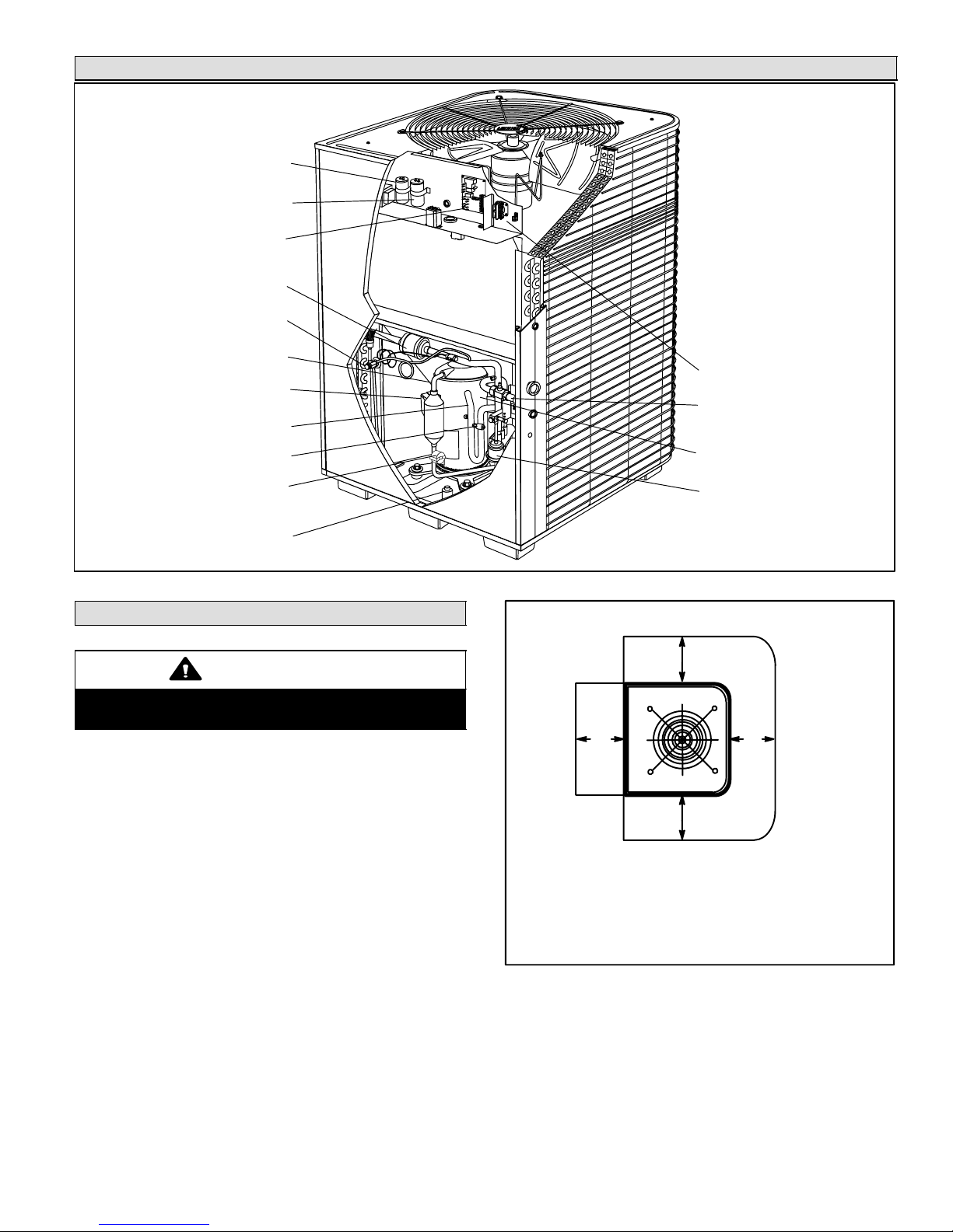
Parts Arrangement
RUN CAPACITOR
START CAPACITOR
(−024 UNIT ONLY)
DEFROST CONTROL
CHARGE COMPENSATOR
(−048 UNITS)
TXV/CHECK VALVE
DISCHARGE LINE
COMPRESSOR TERMINAL PLUG
VAPOR LINE
LOW PRESSURE SWITCH
DISCHARGE TEMPERATURE
SENSOR
HIGH PRESSURE SWITCH
Setting the Unit
CAUTION
In order to avoid injury, take proper precaution when
lifting heavy objects.
CONTACTOR
VAPOR VALVE AND GAUGE
PORT
TWO−STAGE COMPRESSOR
FILTER DRIER
Figure 1
Installation Clearances
as noted
These units operate under a wide range of weather conditions; therefore, several factors must be considered when
positioning the outdoor unit. The unit must be positioned to
give adequate clearances for sufficient airflow and servicing. Refer to figure 2 for installation clearances.
1. Place a sound−absorbing material, such as Isomode,
under the unit if it will be installed in a location or position that will transmit sound or vibration to the living
area or adjacent buildings.
2. Mount unit high enough above ground or roof to allow
adequate drainage of defrost water and prevent ice
build−up.
3. In heavy snow areas, do not locate unit where drifting
will occur. The unit base should be elevated above the
depth of average snows.
NOTE − Elevation of the unit may be accomplished by
constructing a frame using suitable materials. If a support frame is constructed, it must not block drain holes
in unit base.
Page 3
30"
(762 mm)
NOTE − A service access clearance of 30" (762 mm) must be maintained in front of the service access panel. Clearance to one side must
be 36" (914 mm). Clearance to one of the remaining two sides may be
12" (305 mm) and the final side may be 6" (152 mm).
NOTE − A clearance of 24" (610 mm) must be maintained between
two units.
NOTE − 48" (1219 mm) clearance required on top
of unit. Maximum soffit overhang is 36" (914 mm).
as noted
as noted
Figure 2
4. When installed in areas where low ambient temperatures exist, locate unit so winter prevailing winds do
not blow directly into outdoor coil.
5. Locate unit away from overhanging roof lines which
would allow water or ice to drop on, or in front of, coil
or into unit.
HPXA16 SERIES
Page 4
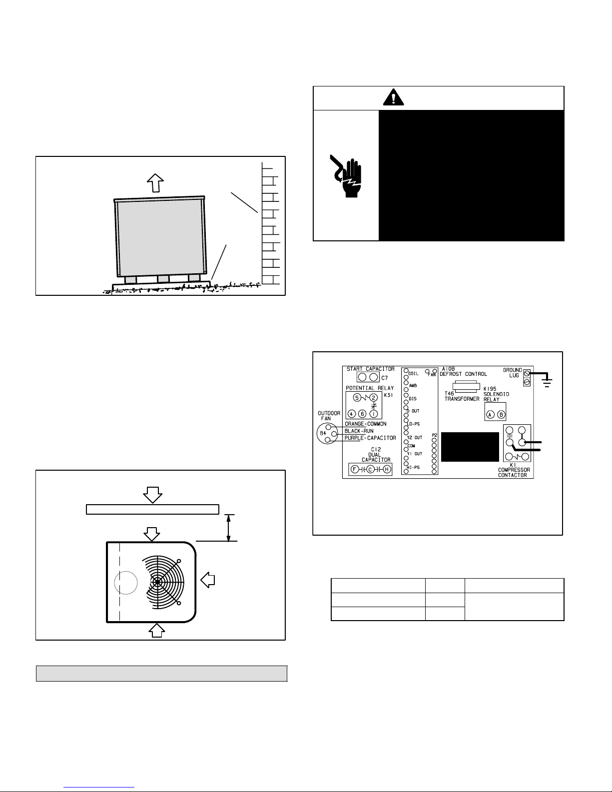
Slab Mounting
color coded, temperature
When installing unit at grade level, top of slab should be
high enough above the grade so that water from higher
ground will not collect around unit. See figure 3. Slab
should have a slope tolerance away from the building of 2
degrees or 2 inches per 5 feet (51 mm per 1.5 m). This will
prevent ice build−up under unit during a defrost cycle. Refer to roof mounting section for barrier construction if unit
must face prevailing winter winds.
Slab Mounting
discharge air
2 DEGREES OR
2 IN. PER 5 FOOT
(51 MM PER 1.5 M)
SLOPE
TOLERANCE
AWAY FROM
BUILDING
STRUCTURE
ground level
building
structure
mounting
slab
Figure 3
Roof Mounting
Install the unit a minimum of 6 inches (152 mm) above the
roof surface to avoid ice build−up around the unit. Locate
the unit above a load bearing wall or area of the roof that
can adequately support the unit. Consult local codes for
rooftop applications.
If unit coil cannot be mounted away from prevailing winter
winds, a wind barrier should be constructed. See figure 4.
Size barrier at least the same height and width as outdoor
unit. Mount barrier 24 inches (610 mm) from the sides of
the unit in the direction of prevailing winds.
Rooftop Wind Barrier Construction
prevailing winter
winds
wind barrier
inlet air
inlet air
24"
(610
mm)
inlet air
Figure 4
Electrical
In the U.S.A., wiring must conform with current local codes
and the current National Electric Code (NEC). In Canada,
wiring must conform with current local codes and the current
Canadian Electrical Code (CEC).
Refer to the furnace or blower coil installation instructions
for additional wiring application diagrams and refer to unit
nameplate for minimum circuit ampacity and maximum
overcurrent protection size.
WARNING
Electric Shock Hazard. Can cause injury or death. Unit must be grounded
in accordance with national and local
codes.
Line voltage is present at all components when unit is not in operation on
units with single-pole contactors. Disconnect all remote electric power supplies before opening access panel.
Unit may have multiple power supplies.
1. Install line voltage power supply to unit from a properly
sized disconnect switch.
2. Ground unit at unit disconnect switch or to an earth
ground.
NOTE − Connect conduit to the unit using a proper
conduit fitting. Units are approved for use only with
copper conductors. Refer to figure 5 for high voltage
field wiring diagram. A complete unit wiring diagram is
located on the back side of the unit’s access panel.
Typical Field Wiring Diagram
GND
READ
WARNING
AND NOTE
WARNING! − ELECTRIC SHOCK HAZARD. Can cause INJURY or
DEATH. Unit must be grounded in accordance with national and local
codes.
NOTE − For use with copper conductors only. Refer to unit rating
plate for minimum circuit ampacity and maximum over-current
protection size.
Figure 5
NOTE − For proper voltages, select thermostat wire
gauge per the following chart:
Wire run length AWG # Insulation type
less than 100’ (30m) 18
more than 100’ (30m) 16
3. Install room thermostat (ordered separately) on an inside wall approximately in the center of the conditioned
area and 5 feet (1.5 m) from the floor. It should not be
installed on an outside wall or where it can be effected
by sunlight, drafts or vibrations.
4. Install low voltage wiring from outdoor to indoor unit
and from thermostat to indoor unit. See figures 6
through 8.
NOTE − 24V, Class II circuit connections are made in
the low voltage junction box.
color−coded, temperature
rating 35ºC minimum
L2
L1
208−
230/
60/1
504954M 08/06
Page 4
Page 5
HPXA16 Outdoor Unit and Blower Unit
Thermostat Designations
(Some connections may not apply. Refer to specific thermostat
and indoor unit.)
Outdoor Unit Indoor Unit TB1
Defrost
Board
Y2
OUT
R
Y1
C
W1
O
Y2
R
W3
W2
Y1
G
C
W1
O
Y2
A2 Thermostat
R
Y1
G
C
W1
O
Y2
HPXA16 Outdoor Unit and CB31MV/CB32MV
Thermostat Designations
(Some connections may not apply. Refer to specific thermostat
and indoor unit.)
Outdoor Unit
Defrost
W1
Board
Y2
OUT
Y2
R
Y1
C
O
CB31MV /
CBX32MV TB1
DS
R
W3
W2
Y1
G
C
W1
O
Y2
SignatureStat
A2 Thermostat
D
R
H
L
Y1
G
C
W2
O
W1
Y2
RT−
14
Figure 6
Figure 7
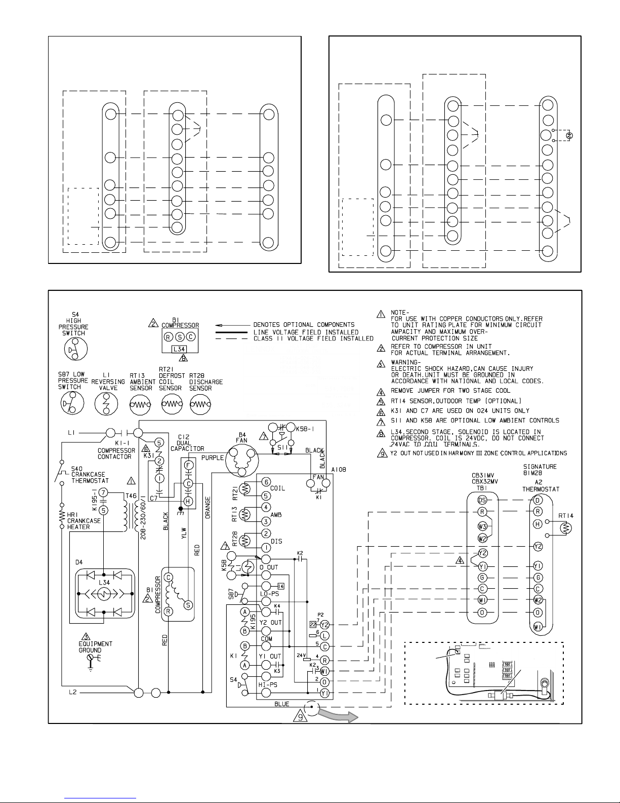
HPXA16 Wiring Diagram
Figure 8
Page 5
BLUE WIRE
Y2 OUT
DEFROST
BOARD
DETAIL
Shipped as shown above with terminal crimped to blue wire; use terminal or
cut off terminal and splice blue wire with Y2 wire to indoor unit.
WITH CRIMPED
TERMINAL
HPXA16 SERIES
Page 6
Refrigerant Piping
If the HPXA16 unit is being installed with a new indoor coil
and line set, the refrigerant connections should be made
as outlined in this section. If an existing line set and/or indoor coil is going to be used to complete the HPXA16 system, refer to the following section which includes flushing
procedures.
Field refrigerant piping consists of liquid and vapor lines
from the outdoor unit (sweat connections) to the indoor coil
(flare or sweat connections). Use Lennox L15 (sweat, nonflare) series line sets as shown in table 2 or use field-fabricated refrigerant lines. Valve sizes are also listed in table 2.
Refrigerant Connections − HPXA16 Matched
with New Indoor Coil and Line Set
If an existing indoor coil which was equipped with an RFCI
metering device is being replaced, the liquid line must also
be replaced prior to the installation of the HPXA16 unit.
Table 2
Refrigerant Line Sets
Field
Connections
Model
−024
−036
−048
−060 3/8 in.
Liquid
Line
3/8 in.
(10 mm)
(10 mm)
Vapor
Line
7/8 in
(22 mm)
1−1/8 in.
(29 mm)
Recommended Line Set
Liquid
Line
3/8 in.
(10 mm)
3/8 in.
(10 mm)
Vapor
Line
7/8 in
(22 mm)
1−1/8 in.
(29 mm)
L15
Line Sets
L15−65
15 ft. − 50 ft.
(4.6 m − 15 m)
Field
Fabricated
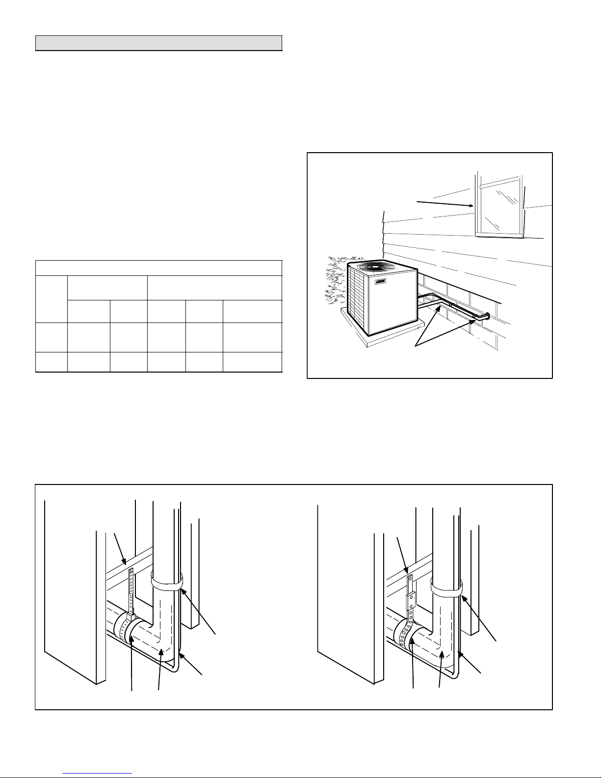
1. PlacementBe aware some localities are adopting
sound ordinances based on how noisy the unit is at the
neighbors’ home, not at the original installation. Install
the unit as far as possible from the property line. When
possible, do not install the unit directly outside a bedroom window. Glass has a very high level of sound
transmission. Figure 9 shows how to place the outdoor
unit and line set.
Outside Unit Placement and Installation
Install unit away
from windows
Two 90° elbows installed in line set
will reduce line set vibration.
NOTE − Units are designed for line sets of up to fifty feet
(15m).
Installing Refrigerant Line
Pay close attention to line set isolation during installation of
any heat pump or a/c system. When properly isolated from
building structures (walls, ceilings. floors), the refrigerant
lines will not create unnecessary vibration and subsequent
noises. Also, consider the following when placing and
installing a high−efficiency outdoor unit:
Refrigerant Line Sets: Transition From Vertical To Horizontal
ANCHORED
HEAVY NYLON
WIRE TIE
WALL
STUD
Strap Liquid
Line To Vapor Line
Figure 9
2. Line Set IsolationThe following illustrations demonstrate procedures which ensure proper refrigerant
line set isolation. Figure 10 shows how to make a transition from horizontal to vertical. Figure 11 shows how
to install line sets on vertical runs. Figure 12 shows
how to install line sets on horizontal runs.
AUTOMOTIVE
MUFFLER-TYPE
HANGER
WALL
STUD
Strap Liquid Line
To Vapor Line
METAL
SLEEVE
504954M 08/06
VAPOR LINE − WRAPPED
IN ARMAFLEX
LIQUID LINE
Figure 10
Page 6
METAL
SLEEVE
LIQUID LINE
VAPOR LINE − WRAPPED
IN ARMAFLEX
Page 7
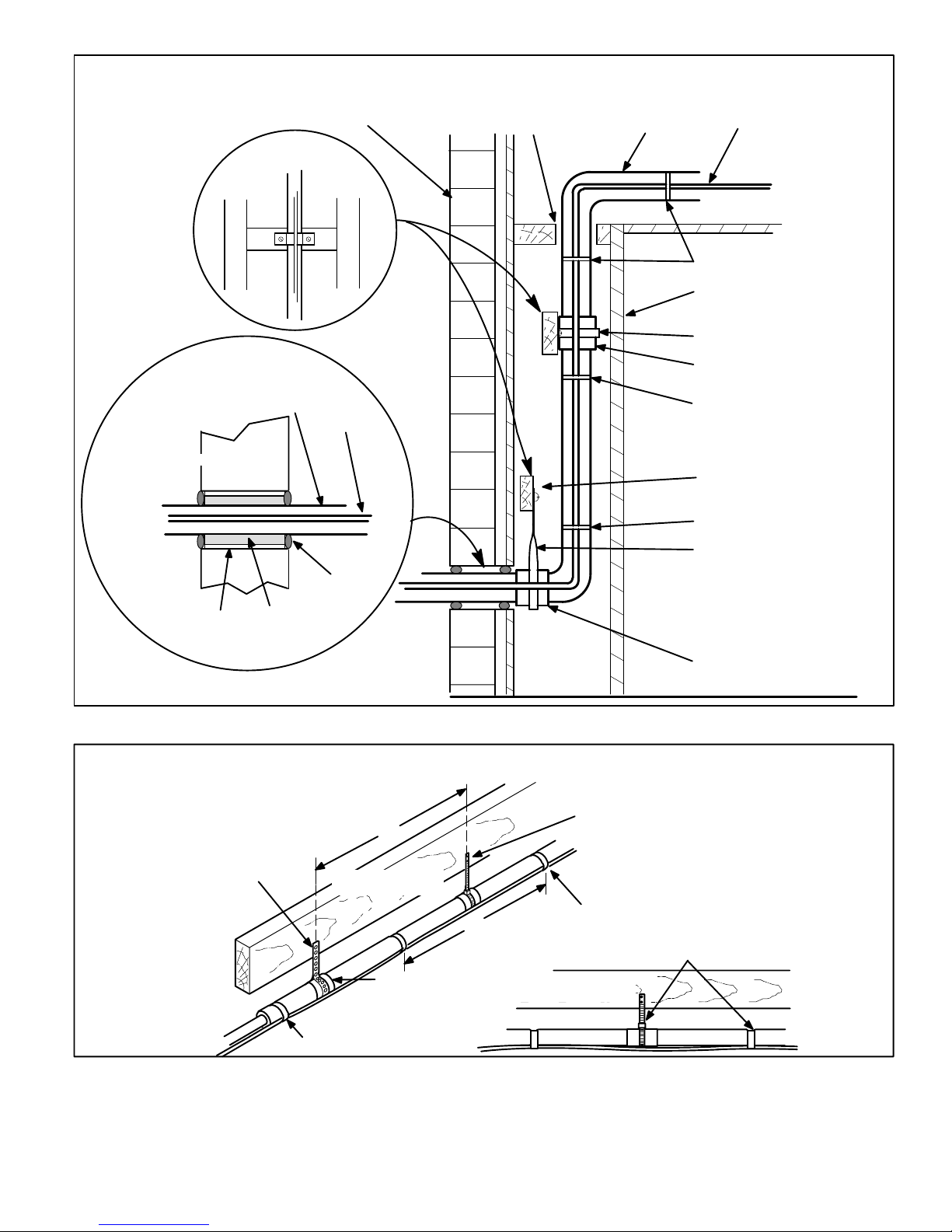
Refrigerant Line Sets: Installing Vertical Runs (new construction shown)
NOTE − Similar installation practices should be used if line set is to be installed on exterior of outside wall.
IMPORTANT - Refrigerant
lines must not contact wall.
LIQUID LINEVAPOR LINE
WIRE TIE
INSIDE WALL
STRAP
SLEEVE
WIRE TIE
WOOD BLOCK
WIRE TIE
STRAP
VAPOR LINE WRAPPED
IMPORTANT!
Refrigerant
lines must
not contact
structure.
WOOD BLOCK
BETWEEN STUDS
WITH ARMAFLEX
OUTSIDE WALL
OUTSIDE WALL
LIQUID
LINE
PVC PIPE
FIBERGLASS
INSULATION
Refrigerant Line Sets: Installing Horizontal Runs
To hang line set from joist or rafter,
use either metal strapping material
or anchored heavy nylon wire ties.
STRAPPING MATERIAL
(Around vapor line only)
CAULK
8 feet
FLOOR JOIST OR
ROOF RAFTER
METAL
SLEEVE
Figure 11
8 feet
WIRE TIE
(Around vapor line only)
TAPE OR
WIRE TIE
FLOOR JOIST OR
ROOF RAFTER
SLEEVE
Strap the vapor line to the joist or
rafter at 8 ft. intervals then strap
the liquid line to the vapor line.
TAPE OR WIRE TIE
Figure 12
Page 7
HPXA16 SERIES
Page 8
Isolation Grommets
Locate the provided isolation grommets. Use a knife to slit
the webbing on each grommet. Slide larger grommet onto
vapor line and smaller grommet onto liquid line. Insert
grommets into mullion to isolate refrigerant lines from
sheet metal edges.
WARNING
Polyol ester (POE) oils used with HFC−410A refrigerant absorb moisture very quickly. It is very important that the refrigerant system be kept closed
as much as possible. DO NOT remove line set caps
or service valve stub caps until you are ready to
make connections.
Brazing Connection Procedure
1. The end of the refrigerant line must be cut square and
its internal shape must remain round. The line must be
free of nicks or dents and must be deburred (I.D. and
O.D.)
2. Before making line set connections, use dry nitrogen
to purge the refrigerant piping. This will help to prevent
oxidation and the introduction of moisture into the system.
3. Use silver alloy brazing rods (5 or 6 percent minimum
silver alloy for copper−to−copper brazing or 45 percent
silver alloy for copper−to−brass or copper−to−steel
brazing). Wrap a wet cloth around the valve body and
the copper tube stub. Remove light maroon washers
from service valves and shield light maroon stickers in
order to protect them during brazing. Braze the line set
to the service valve.
4. Quench the joint with water or a wet cloth to prevent
heat damage to the valve core and opening port.
NOTE − The tube end must stay bottomed in the fitting
during final assembly to ensure proper seating, sealing and rigidity.
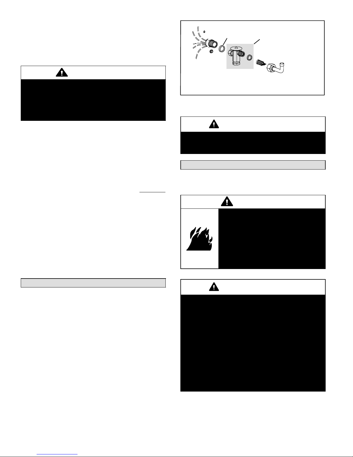
Metering Device Installation
O−RING
DISTRIBUTOR
NOTE − If necessary, remove HCFC−22 flow control device (fixed
orifice/check expansion valve) from existing line set before installing
HFC−410A approved expansion valve and o−ring.
EXPANSION VALVE &
O−RING (See NOTE)
STRAINER
LIQUID LINE
STUB
Figure 13
IMPORTANT
Failure to remove a fixed orifice when installing an
expansion valve on the indoor coil will result in improper operation and damage to the system.
Flushing Existing Line Set & Indoor Coil
NOTE − If the indoor unit line and set are new, skip this section and go on to the Manifold Gauge Set section.
WARNING
Danger of fire. Bleeding the refrigerant charge from only the high side
may result in the low side shell and
suction tubing being pressurized. Application of a brazing torch while
pressurized may result in ignition of
the refrigerant and oil mixture − check
the high and low pressures before unbrazing.
Refrigerant Metering Device
HPXA16 units may be used in check expansion valve
(CTXV) systems only. See indoor coil installation instructions and the Lennox engineering handbook for approved
HFC−410A TXV match−ups and application information.
NOTE − HFC−410A systems will not operate properly with
an HCFC−22 valve.
Check Expansion Valve Systems
Check expansion valves equipped with either Chatleff or
flare−type fittings are available from Lennox. Refer to the
Engineering Handbook for applicable expansion valves for
use with specific match-ups.
If you install a check expansion valve with an indoor coil
that includes a fixed orifice, remove the orifice before the
check expansion valve is installed. See figure 13 for installation of the check expansion valve.
504954M 08/06
IMPORTANT
If this unit is being matched with an approved line
set or indoor coil which was previously charged
with HCFC−22 refrigerant, or if it is being matched
with a coil which was manufactured before January of 1999, the coil and line set must be flushed
prior to installation. Take care to empty all existing
traps.
Polyol ester (POE) oils are used in Lennox units
charged with HFC−410A refrigerant. Residual mineral oil can act as an insulator, preventing proper
heat transfer. It can also clog the check expansion
valve, reducing system performance and capacity.
Failure to properly flush the system per the instructions below will void the warranty.
Page 8
Page 9
IMPORTANT
The Environmental Protection Agency prohibits the
intentional venting of HFC refrigerants during maintenance, service, repair and disposal of appliance.
Approved methods of recovery, recycling or reclaiming must be followed.
CAUTION
This procedure should not be performed on systems which contain contaminants (Example: compressor burn out).
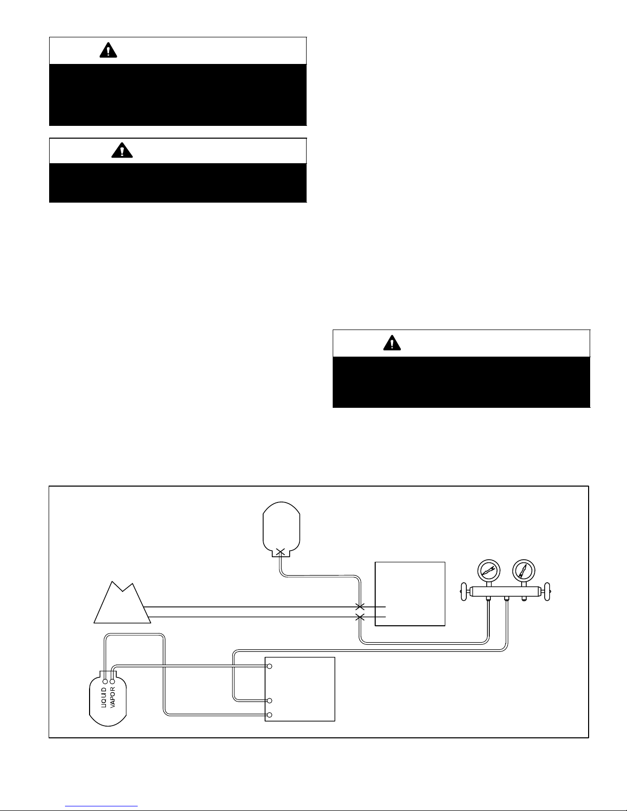
Required Equipment
You will need the following equipment in order to flush the
existing line set and indoor coil: two clean HCFC−22 recovery bottles, an oilless recovery machine with a pump down
feature, and two sets of gauges (one for use with HCFC−22
and one for use with the HFC−410A).
Flushing Procedure
1. Remove existing HCFC−22 refrigerant using the appropriate procedure below.
If the existing outdoor unit is not equipped with
shut−off valves, or if the unit is not operational
AND you plan to use the existing HCFC−22 refrigerant to flush the system −
Disconnect all power to the existing outdoor unit.
Connect to the existing unit, a clean recovery cyl-
inder and the recovery machine according to the
instructions provided with the recovery machine.
Remove all HCFC−22 refrigerant from the existing
system. Check gauges after shutdown to confirm
that the entire system is completely void of refrigerant.
Disconnect the liquid and vapor lines from the ex-
isting outdoor unit.
If the existing outdoor unit is equipped with
manual shut−off valves AND you plan to use NEW
HCFC−22 refrigerant to flush the system −
Start the existing HCFC−22 system in the cooling
mode and close the liquid line valve.
Pump all of the existing HCFC−22 refrigerant back
into the outdoor unit. (It may be necessary to bypass the low pressure switches to ensure complete refrigerant evacuation.)
When the low side system pressures reach 0 psig,
close the vapor line valve.
Disconnect all power to the existing outdoor unit.
Check gauges after shutdown to confirm that the
valves are not allowing refrigerant to flow back into
the low side of the system.
Disconnect the liquid and vapor lines from the ex-
isting outdoor unit.
2. Remove the existing outdoor unit. Set the new
HFC−410A unit and follow the brazing connection procedure (see page 8) to make line set connections.
DO NOT install metering device at this time.
3. Make low voltage and line voltage connections to the
new outdoor unit. DO NOT turn on power to the unit
or open the outdoor unit service valves at this
time.
IMPORTANT
The line set and indoor coil must be flushed with
at least the same amount of clean refrigerant that
previously charged the system. Check the charge
in the flushing cylinder before proceeding.
4. Remove the existing refrigerant flow control orifice or
thermal expansion/check valve before continuing with
flushing procedures. The existing devices are not approved for use with HFC−410A refrigerant and may
prevent proper flushing. Use a field−provided fitting to
reconnect the lines.
EXISTING
INDOOR COIL
RECOVERY CYLINDER
Inverted HCFC−22 Cylinder
(Contains clean
HCFC−22 to be used for
flushing)
EXISTING VAPOR LINE
EXISTING LIQUID LINE
Flushing Connections
VAPOR LINE
SERVICE VALVE
LIQUID LINE
SERVICE VALVE
Tank Return
Inlet
Discharge
RECOVERY MACHINE
Figure 14
Page 9
Low
Pressure
HPXA16
UNIT
NOTE − The inverted HCFC−22 cylinder must contain at least the
same amount of refrigerant as was
recovered from the existing system.
GAUGE MANIFOLD
High
Pressure
ClosedOpened
HPXA16 SERIES
Page 10

5. Remove the pressure tap valve cores from the
HPXA16 unit’s service valves. Connect an HCFC−22
cylinder with clean refrigerant to the vapor service
valve. Connect the HCFC−22 gauge set to the liquid
line valve and connect a recovery machine with an
empty recovery tank to the gauge set.
6. Set the recovery machine for liquid recovery and start
the recovery machine. Open the gauge set valves to
allow the recovery machine to pull a vacuum on the existing system line set and indoor coil.
7. Invert the cylinder of clean HCFC−22 and open its
valve to allow liquid refrigerant to flow into the system
through the vapor line valve. Allow the refrigerant to
pass from the cylinder and through the line set and the
indoor coil before it enters the recovery machine.
8. After all of the liquid refrigerant has been recovered,
switch the recovery machine to vapor recovery so that
all of the HCFC−22 vapor is recovered.
NOTE − A single system flush should remove all of the
mineral oil from the existing refrigerant lines and indoor coil. A second flushing may be done (using clean
refrigerant) if insufficient amounts of mineral oil were
removed during the first flush. Each time the system
is flushed, you must allow the recovery machine
to pull a vacuum on the system at the end of the
procedure.
9. Close the valve on the inverted HCFC−22 drum and
the gauge set valves. Pump the remaining refrigerant
out of the recovery machine and turn the machine off.
10. Use dry nitrogen to break the vacuum on the refrigerant lines and indoor coil before removing the recovery
machine, gauges and HCFC−22 refrigerant drum. Reinstall pressure tap valve cores into HPXA16 service
valves.
11. Install the provided check expansion valve (approved
for use with HFC−410A refrigerant) in the liquid line at
the indoor coil.
Manifold Gauge Set
Manifold gauge sets used with systems charged with
HFC−410A refrigerant must be capable of handling the
higher system operating pressures. The gauges should be
rated for use with pressures of 0 − 800 on the high side and
a low side of 30" vacuum to 250 psi with dampened speed
to 500 psi. Gauge hoses must be rated for use at up to 800
psi of pressure with a 4000 psi burst rating.
Service Valves
The liquid line and vapor line service valves (figures 15 and
16) and gauge ports are used for leak testing, evacuating,
charging, and checking charge. See table for torque requirements.
Front-Seated Liquid Line Service Valve
(Valve Shown Closed)
Insert hex wrench here
CAP
STEM
CAP
(Valve Shown Open)
insert hex wrench here
CAP
STEM
CAP
Service port Is open to
line set when valve is
closed (front seated)
SERVICE
PORT
To
indoor coil
To outdoor coil
SERVICE
PORT
To
indoor coil
To outdoor coil
Figure 15
Ball−Type Vapor Valve (Valve Closed)
STEM
USE ADJUSTABLE WRENCH
TO OPEN: ROTATE STEM
COUNTER-CLOCKWISE 90°.
TO CLOSE: ROTATE STEM
CLOCKWISE 90°.
TO
INDOOR
COIL
CAP
STEM
SERVICE PORT
SCHRADER VALVE
TO
OUTDOOR
COIL
BALL (SHOWN
CLOSED)
SERVICE
PORT CAP
Figure 16
Each valve is equipped with a service port which has a factory−installed Schrader valve. A service port cap protects
the Schrader valve from contamination and serves as the
primary leak seal.
504954M 08/06
Page 10
Page 11

IMPORTANT
Service valves are closed to the outdoor unit and
open to line set connections. Do not open until refrigerant lines have been leak tested and evacuated.
All precautions should be exercised in keeping the
system free from dirt, moisture and air.
To Access Schrader Port:
1. Remove service port cap with an adjustable wrench.
2. Connect gauge to the service port.
3. When testing is completed, replace service port cap. Replace the stem cap. Tighten finger tight; then torque per
table 1 (Page 2).
To Open Front-Seated Service Valves:
1. Remove stem cap with an adjustable wrench.
2. Use a service wrench with a hex−head extension
(3/16" for liquid-line valve sizes; 5/16" for vapor-line
valve sizes) to back the stem out counterclockwise as
far as it will go.
3. Replace the stem cap. Tighten finger tight; then torque
per table 1 (Page 2).
To Close Front-Seated Service Valves:
1. Remove the stem cap with an adjustable wrench.
2. Use a service wrench with a hex−head extension
(3/16" for liquid-line valve sizes; 5/16" for vapor-line
valve sizes) to turn the stem clockwise to seat the
valve. Tighten it firmly.
3. Replace the stem cap. Tighten finger tight; then torque
per table 1 (Page 2).
Ball-Type Service Valve (Vapor Line)
Ball-type service valves function the same way as the other valves; the difference is in the construction. These
valves are not rebuildable. If a valve has failed, you must
replace it. A ball valve is illustrated in figure 16.
The ball valve is equipped with a service port with a factory−
installed Schrader valve. A service port cap protects the
Schrader valve from contamination and assures a leak−
free seal.
Leak Testing
After the line set has been connected to the indoor and outdoor units, the line set connections and indoor unit must be
checked for leaks.
WARNING
Refrigerant can be harmful if it is inhaled. Refrigerant must be used and recovered responsibly.
Failure to follow this warning may result in personal
injury or death.
WARNING
Fire, Explosion and Personal Safety
Hazard.
Failure to follow this warning could
result in damage, personal injury or
death.
Never use oxygen to pressurize or
purge refrigeration lines. Oxygen,
when exposed to a spark or open
flame, can cause damage by fire and/
or an explosion, that could result in
personal injury or death.
WARNING
When using a high pressure gas such
as dry nitrogen to pressurize a refrigeration or air conditioning system,
use a regulator that can control the
pressure down to 1 or 2 psig (6.9 to
13.8 kPa).
Using an Electronic Leak Detector
1. Connect a cylinder of HFC−410A to the center port of
the manifold gauge set.
2. With both manifold valves closed, open the valve on
the HFC−410A cylinder (vapor only).
3. Open the high pressure side of the manifold to allow
the HFC−410A into the line set and indoor unit. Weigh
in a trace amount of HFC−410A . [A trace amount is a
maximum of 2 ounces (57 g) or 3 pounds (31 kPa)
pressure.] Close the valve on the HFC−410A cylinder
and the valve on the high pressure side of the manifold
gauge set. Disconnect the HFC−410A cylinder.
4. Connect a cylinder of dry nitrogen with a pressure regulating valve to the center port of the manifold gauge
set.
5. Connect the manifold gauge set high pressure hose to
the vapor valve service port. (Normally, the high pres-
sure hose is connected to the liquid line port; however,
connecting it to the vapor port better protects the manifold gauge set from high pressure damage.)
6. Adjust the dry nitrogen pressure to 150 psig (1034
kPa). Open the valve on the high side of the manifold
gauge set which will pressurize line set and indoor unit.
7. After a few minutes, open a refrigerant port to ensure
the refrigerant you added is adequate to be detected.
(Amounts of refrigerant will vary with line lengths.)
Check all joints for leaks. Purge dry nitrogen and
HFC−410A mixture. Correct any leaks and recheck.
IMPORTANT
Leak detector must be capable of sensing HFC refrigerant.
Page 11
HPXA16 SERIES
Page 12

Evacuation
Evacuating the system of noncondensables is critical for
proper operation of the unit. Noncondensables are defined
as any gas that will not condense under temperatures and
pressures present during operation of an air conditioning
system. Noncondensables and water vapor combine with
refrigerant to produce substances that corrode copper piping and compressor parts.
IMPORTANT
Use a thermocouple or thermistor electronic vacuum
gauge that is calibrated in microns. Use an instrument
that reads from 50 microns to at least 23,000 microns.
1. Connect manifold gauge set to the service valve ports
as follows:
low pressure gauge to vapor line service valve
high pressure gauge to liquid line service valve
2. Connect micron gauge.
3. Connect the vacuum pump (with vacuum gauge) to
the center port of the manifold gauge set.
4. Open both manifold valves; start the vacuum pump.
5. Evacuate the line set and indoor unit to an absolute
pressure of 23,000 microns (29.01 inches of mercury). During the early stages of evacuation, it is desirable to close the manifold gauge valve at least once to
determine if there is a rapid rise in absolute pressure.
A rapid rise in pressure indicates a relatively large
leak. If this occurs, repeat the leak testing procedure.
NOTE − The term absolute pressure means the total
actual pressure within a given volume or system,
above the absolute zero of pressure. Absolute pressure in a vacuum is equal to atmospheric pressure minus vacuum pressure.
6. When the absolute pressure reaches 23,000 microns
(29.01 inches of mercury), close the manifold gauge
valves, turn off the vacuum pump and disconnect the
manifold gauge center port hose from vacuum pump.
Attach the manifold center port hose to a dry nitrogen
cylinder with pressure regulator set to 150 psig (1034
kPa) and purge the hose. Open the manifold gauge
valves to break the vacuum in the line set and indoor
unit. Close the manifold gauge valves.
WARNING
Danger of Equipment Damage! Avoid deep vacuum operation. Do not use compressors to evacuate a system. Extremely low vacuums can cause
internal arcing and compressor failure. Damage
caused by deep vacuum operation will void warranty.
7. Shut off the dry nitrogen cylinder and remove the manifold gauge hose from the cylinder. Open the manifold
gauge valves to release the dry nitrogen from the line
set and indoor unit.
8. Reconnect the manifold gauge to the vacuum pump,
turn the pump on, and continue to evacuate the line set
and indoor unit until the absolute pressure does not
rise above 500 microns (29.9 inches of mercury) within
a 20−minute period after shutting off the vacuum pump
and closing the manifold gauge valves.
9. When the absolute pressure requirement above has
been met, disconnect the manifold hose from the vacuum pump and connect it to an upright cylinder of
HFC−410A refrigerant. Open the manifold gauge
valves to break the vacuum from 1 to 2 psig positive
pressure in the line set and indoor unit. Close manifold
gauge valves and shut off the HFC−410A cylinder and
remove the manifold gauge set.
Start−Up
IMPORTANT
If unit is equipped with crankcase heater, it should
be energized 24 hours before unit start−up to prevent compressor damage as a result of slugging.
1. Rotate fan to check for frozen bearings or binding.
2. Inspect all factory− and field-installed wiring for loose
connections.
3. After evacuation is complete, open the liquid line and
vapor line service valves (counterclockwise) to release refrigerant charge (contained in outdoor unit)
into the system.
4. Replace stem caps and secure finger tight, then tighten an additional (1/6) one-sixth of a turn.
5. Check voltage supply at the disconnect switch. The
voltage must be within the range listed on the unit
nameplate. If not, do not start the equipment until the
power company has been consulted and the voltage
condition has been corrected.
6. Set the thermostat for a cooling demand. Turn on power to indoor blower unit and close the outdoor unit disconnect to start the unit.
7. Recheck voltage while the unit is running. Power must
be within range shown on the nameplate.
Refrigerant Charging
This system is charged with HFC−410A refrigerant which
operates at much higher pressures than HCFC−22. The
field−provided check expansion valve for the indoor unit
must be approved for use with HFC−410A. This unit is NOT
approved for use with coils which include metering orifices
or capillary tubes.
Factory Charge
The unit is factory−charged with the amount of HFC−410A
refrigerant indicated on the unit rating plate. This charge is
based on a matching indoor coil and outdoor coil with a 15
foot (4.6 m) line set. For varying lengths of line set, refer to
table 3 for refrigerant charge adjustment.
504954M 08/06
Page 12
Page 13

EXPANSION/
CHECK VALVE
LOW
PRESSURE
HPXA16 Cooling Cycle (Showing Gauge Manifold Connections)
HUGH
PRESSURE
BIFLOW
FILTER /
DRIER
MUFFLER
DISTRIBUTOR
OUTDOOR
COIL
OUTDOOR UNIT
REVERSING VALVE
NOTE − ARROWS INDICATE
DIRECTION OF REFRIGERANT FLOW
INDOOR UNIT
GAUGE MANIFOLD
TO
HFC−410
A DRUM
NOTE − Use gauge ports on vapor line valve and liquid valve for evacuating refrigerant lines and indoor coil. Use vapor
gauge port to measure vapor pressure during charging.
LIQUID
LINE
SERVICE
PORT
COMPRESSOR
VAPOR
SERVICE
PORT
VAPOR
LINE
VALV E
EXPANSION/CHECK VALVE
Figure 17
Table 3
Refrigerant Charge per Line Set Lengths
Liquid Line
Set Diameter
3/8 in. (9.5mm) 3 ounces per 5 feet (85 grams per 1.52 meter)
*Add the amount shown if line length is greater than 15’ (4.57m), subtract the amount shown if less than 15’.
Ounces per 5 feet (grams per 1.52 meter)
adjust from 15 ft. (4.57m) line set*
IMPORTANT
Mineral oils are not compatible with HFC−410A. If
oil must be added, it must be a polyol ester oil.
The compressor is charged with sufficient polyol
ester oil for approved line set lengths.
Checking Charge
The outdoor unit should be charged during warm weather.
However, applications arise in which charging must occur
in the colder months. The method of charging is deter-
mined by the outdoor ambient temperature.
Measure the liquid line temperature and the outdoor ambient temperature as outlined below:
1. Connect the manifold gauge set to the service valves:
low pressure gauge to vapor valve service port
high pressure gauge to liquid valve service port
Close manifold gauge set valves. Connect the center
manifold hose to an upright cylinder of HFC−410A. See
figure 17.
2. Set the room thermostat to call for heat. This will
create the necessary load for properly charging the
system in the cooling cycle.
3. Record outdoor ambient temperature using a digital
thermometer.
4. When the heating demand has been satisfied, switch
the thermostat to cooling mode with a set point of 68F
Page 13
(20C). When pressures have stabilized, use a digital
thermometer to record the liquid line temperature.
5. The outdoor temperature will determine which charging method to use. Proceed with whichever of the following charging procedure deemed appropriate for the
situation.
Charge Using the Weigh-in Method –
Outdoor Temperature < 65F (18C)
If the system is void of refrigerant, or if the outdoor ambient
temperature is cool, first, locate and repair any leaks and
then weigh in the refrigerant charge into the unit.
1. Recover the refrigerant from the unit.
2. Conduct leak check; evacuate as previously outlined.
3. Weigh in the unit nameplate charge. If weighing facilities are not available or if charging the unit during
warm weather, use one of the following procedures.
Charge Using the Subcooling Method –
Outdoor Temperature < 65°F (18°C)
When the outdoor ambient temperature is below 65°F
(18°C), use the subcooling method to charge the unit. It
may be necessary to restrict the air flow through the outdoor coil to achieve pressures in the 325−375 psig
(2240−2585 kPa) range. These higher pressures are necessary for checking the charge. Block equal sections of air
intake panels and move obstructions sideways until the liquid pressure is in the 325−375 psig (2240−2585 kPa) range.
See figure 18.
Blocking Outdoor Coil
Figure 18
VAPOR
SERVICE
PORT
INDOOR
COIL
*Outdoor coil should be blocked one
side at a time with cardboard or plastic
sheet until proper testing pressures
are reached.
cardboard or plastic sheet
*Four−sided unit shown.
HPXA16 SERIES
Page 14

1. With the manifold gauge hose still on the liquid service
port and the unit operating stably, use a digital thermometer to record the liquid line temperature.
2. At the same time, record the liquid line pressure reading.
3. Use a temperature/pressure chart for HFC−410A to
determine the saturation temperature for the liquid line
pressure reading. See table 4.
Table 4
HFC−410A Temperature (°F) − Pressure (Psig)
°F Psig °F Psig °F Psig °F Psig
32 100.8 63 178.5 94 290.8 125 445.9
33 102.9 64 181.6 95 295.1 126 451.8
34 105.0 65 184.3 96 299.4 127 457.6
35 107.1 66 187.7 97 303.8 128 463.5
36 109.2 67 190.9 98 308.2 129 469.5
37 111.4 68 194.1 99 312.7 130 475.6
38 113.6 69 197.3 100 317.2 131 481.6
39 115.8 70 200.6 101 321.8 132 487.8
40 118.0 71 203.9 102 326.4 133 494.0
41 120.3 72 207.2 103 331.0 134 500.2
42 122.6 73 210.6 104 335.7 135 506.5
43 125.0 74 214.0 105 340.5 136 512.9
44 127.3 75 217.4 106 345.3 137 519.3
45 129.7 76 220.9 107 350.1 138 525.8
46 132.2 77 224.4 108 355.0 139 532.4
47 134.6 78 228.0 109 360.0 140 539.0
48 137.1 79 231.6 11 0 365.0 141 545.6
49 139.6 80 235.3 111 370.0 142 552.3
50 142.2 81 239.0 11 2 375.1 143 559.1
51 144.8 82 242.7 11 3 380.2 144 565.9
52 147.4 83 246.5 11 4 385.4 145 572.8
53 150.1 84 250.3 11 5 390.7 146 579.8
54 152.8 85 254.1 11 6 396.0 147 586.8
55 155.5 86 258.0 11 7 401.3 148 593.8
56 158.2 87 262.0 11 8 406.7 149 601.0
57 161.0 88 266.0 11 9 412.2 150 608.1
58 163.9 89 270.0 120 417.7 151 615.4
59 166.7 90 274.1 121 423.2 152 622.7
60 169.6 91 278.2 122 428.8 153 630.1
61 172.6 92 282.3 123 434.5 154 637.5
62 175.4 93 286.5 124 440.2 155 645.0
4. Subtract the liquid line temperature from the saturation
temperature (according to the chart) to determine subcooling. (Saturation temperature − Liquid line tem-
perature = Subcooling)
5. Compare the subcooling value with those in table 5. If
subcooling is greater than shown, recover some refrigerant. If subcooling is less than shown, add some re-
frigerant. Be aware of the HFC−410A refrigerant cylinder. It will be light maroon−colored. Refrigerant should
be added through the vapor line valve in the liquid
state.
NOTE − Some HFC−410A cylinders are equipped with a dip
tube that allows you to draw liquid refrigerant from the bottom of the cylinder without turning the cylinder upside−
down. The cylinder will be marked if it is equipped with a dip
tube.
Table 5
Subcooling Values for Charging
Second Stage (High Capacity)
Model Number
HPXA16−024 11.0 + 1 (6 + .5)
HPXA16−036 8.5 + 1 (4.7 + .5)
HPXA16−048 7.5 + 1 (4.1 + .5)
HPXA16−060 7.0 + 1 (3.9 + .5)
Subcooling Values Conversion Temp. −
Liquid Line Temp. °F (°C)
Charge Using the Approach Method –
Outdoor Temperature >
The following procedure is intended as a general guide and
is for use on expansion valve systems only. For best results, indoor temperature should be 70°F (21°C) to 80°F
(26°C). Monitor system pressures while charging.
1. Record outdoor ambient temperature using a digital
thermometer.
2. Attach high pressure gauge set and operate unit for
several minutes to allow system pressures to stabilize.
3. Compare stabilized pressures with those provided in
tables 6 and 7, Normal Operating Pressures."
65F (18C)
IMPORTANT
Use tables 6 & 7 as a general guide when performing
maintenance checks. This is not a procedure for
charging the unit.
Minor variations in these pressures may be expected due to differences in installations. Significant differences could mean that the system is not
properly charged or that a problem exists with some
component in the system.
Pressures higher than those listed indicate that the
system is overcharged. Pressures lower than those
listed indicate that the system is undercharged.
Continue to check adjusted charge using approach
values.
504954M 08/06
Page 14
Page 15
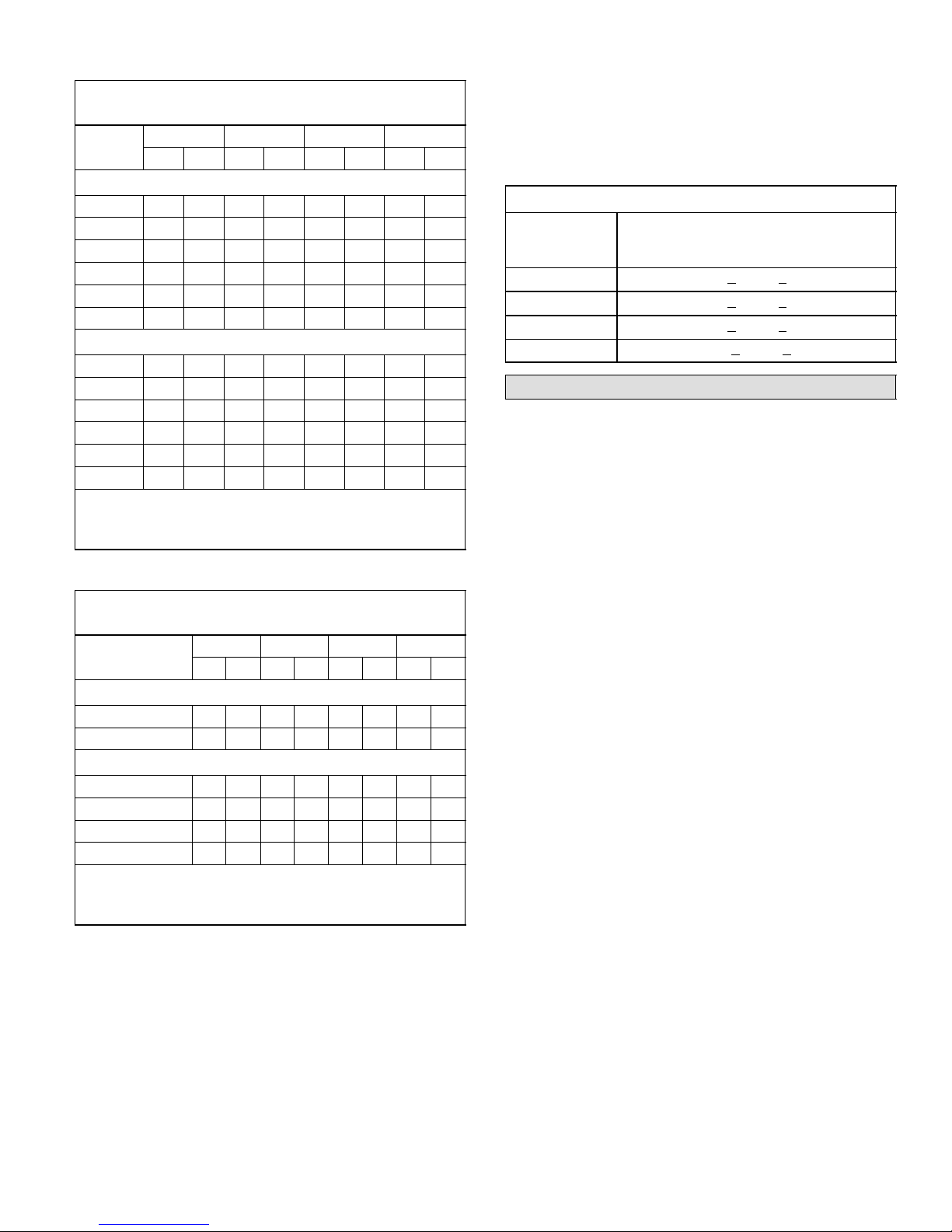
Table 6
°F (°C)**
°F (°C)**
HPXA16 Normal Operating Pressures
COOLING (Liquid ±10 & Vapor ±5 psig)*
°
°
**
65 (18.3) 217 143 227 142 222 140 225 140
75 (23.9) 250 145 262 145 258 143 259 142
85 (29.4) 291 147 305 146 298 145 293 146
95 (35.0) 336 149 352 148 343 147 356 147
105 (40.6) 386 151 403 152 402 147 408 147
115 (49.0) 440 153 458 155 452 152 455 151
65 (18.3) 222 143 244 136 232 134 249 126
75 (23.9) 256 145 282 139 266 136 289 134
85 (29.4) 302 145 325 142 309 139 330 140
95 (35.0) 349 147 377 144 359 142 378 143
105 (40.6) 403 149 428 146 410 144 433 146
115 (49.0) 464 152 488 148 468 147 492 149
*These are most−popular−match−up pressures. Indoor match
up, indoor air quality, and indoor load cause pressures to vary.
**Temperature of the air entering the outside coil.
−024 −036 −048 −060
Liq Vap Liq Va p Liq Vap Liq Vap
First Stage (Low Capacity)
Second Stage (High Capacity)
Table 7
HPXA16 Normal Operating Pressures
HEATING (Liquid ±10 & Vapor ±5 psig)
°
°
**
40 (4.4) 321 99 296 95 315 97 319 93
50 (10) 340 120 310 11 2 330 114 335 111
Second Stage (High Capacity)
20 (−7.0) 273 68 277 60 294 60 300 57
30 (−1.0) 296 80 296 74 303 75 312 70
40 (4.4) 321 95 321 88 314 90 323 83
50 (10) 341 115 341 104 325 106 339 97
*These are most−popular−match−up pressures. Indoor match
up, indoor air quality, and indoor load cause pressures to vary.
**Temperature of the air entering the outside coil.
4. Use the same digital thermometer used to check
outdoor ambient temperature to check liquid line
temperature. Verify the unit charge using the approach
method.
−024 −036 −048 −060
Liq Vap Liq Vap Liq Vap Liq Vap
First Stage (Low Capacity)
5. The difference between the ambient and liquid
temperatures should match values given in table 8. If
the values don’t agree with the those in table 8, add
refrigerant to lower the approach temperature or
recover refrigerant from the system to increase the
approach temperature.
Table 8
Approach Values for Charging
Second Stage (High Capacity) Ap-
Model Number
HPXA16−024 4.0 + 1 (2.2 + .5)
HPXA16−036 7.0 + 1 (3.9 + .5)
HPXA16−048 8.0 + 1 (4.4 + .5)
HPXA16−060 10.0 + 1 (5.6 + .5)
proach Temperature Liquid Line Temp. −
Outdoor Ambient °F (°C)
System Operation
The outdoor unit and indoor blower cycle on demand from
the room thermostat. When the thermostat blower switch
is in the ON position, the indoor blower operates continu-
ously.
Thermostat Operation
Some indoor thermostats incorporate isolating contacts
and an emergency heat function (which includes an amber
indicating light). The thermostat is not included with the
unit and must be purchased separately.
Emergency Heat (Amber Light)
An emergency heat function is designed into some room
thermostats. This feature is applicable when isolation of the
outdoor unit is required, or when auxiliary electric heat is
staged by outdoor thermostats. When the room thermostat is
placed in the emergency heat position, the outdoor unit control circuit is isolated from power and field-provided relays bypass the outdoor thermostats. An amber indicating light simultaneously comes on to remind the homeowner that he is
operating in the emergency heat mode.
Emergency heat is usually used during an outdoor unit
shutdown, but it should also be used following a power outage if power has been off for over an hour and the outdoor
temperature is below 50°F (10°C). System should be left in
the emergency heat mode at least six hours to allow the
crankcase heater sufficient time to prevent compressor
slugging.
Filter Drier
The unit is equipped with a large−capacity biflow filter drier
which keeps the system clean and dry. If replacement is
necessary, order another of like design and capacity. The
replacement filter drier must be suitable for use with
HFC−410A refrigerant.
Page 15
HPXA16 SERIES
Page 16
Defrost System
Defrost System Description
The demand defrost controller measures differential temperatures to detect when the system is performing poorly
because of ice build−up on the outdoor coil. The controller
self−calibrates" when the defrost system starts and after
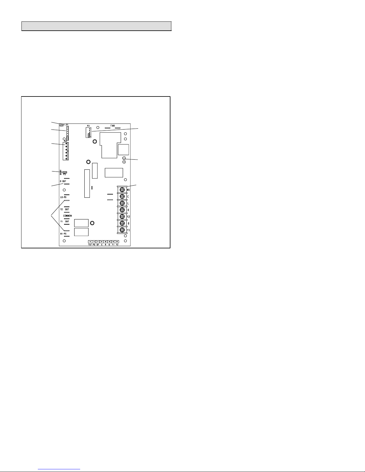
each system defrost cycle. The defrost control board components are shown in figure 19.
Defrost Control Board
Note − Component Locations Vary by Board Manufacturer.
TEST PINS
DEFROST
TERMINATION
PIN SETTINGS
SENSOR
PLUG IN
(COIL & AM-
BIENT
SENSORS)
DELAY
PINS
REVERSING
VALV E
PRESSURE
SWITCH CIR-
CUIT CONNEC-
TIONS
Figure 19
The control monitors ambient temperature, outdoor coil
temperature, and total run time to determine when a defrost cycle is required. The coil temperature probe is designed with a spring clip to allow mounting to the outside
coil tubing. The location of the coil sensor is important for
proper defrost operation.
NOTE − The demand defrost board accurately measures
the performance of the system as frost accumulates on the
outdoor coil. This typically will translate into longer running
time between defrost cycles as more frost accumulates on
the outdoor coil before the board initiates defrost cycles.
Defrost Board Diagnostic LEDs
The state (Off, On, Flashing) of two LEDs on the defrost
board (DS1 [Red] and DS2 [Green]) indicate diagnostics
conditions that are described in table 10 (on page 20).
LOW
AMBIENT
THERMOSTAT
PINS
DIAGNOSTIC
LEDS
24V TERMINAL
STRIP
CONNECTIONS
Defrost Board Pressure Switch Connections
The unit’s automatic reset pressure switches (LO PS − S87
and HI PS − S4) are factory−wired into the defrost board on
the LO−PS and HI−PS terminals, respectively.
Low Pressure Switch (LO−PS)When the low pressure
switch trips, the defrost board will cycle off the compressor,
and the strike counter in the board will count one strike.
The low pressure switch is ignored under the following
conditions:
during the defrost cycle and 90 seconds after the ter-
mination of defrost
when the average ambient sensor temperature is be-
low 15° F (−9°C)
for 90 seconds following the start up of the compressor
during "test" mode
High Pressure Switch (HI−PS)When the high pressure
switch trips, the defrost board will cycle off the compressor,
and the strike counter in the board will count one strike.
Defrost Board Pressure Switch Settings
High Pressure (auto reset) − trip at 590 psig; reset at 418
psig.
Low Pressure (auto reset) − trip at 25 psig; reset at 55
psig.
Pressure Switch 5−Strike Lockout
The internal control logic of the board counts the pressure
switch trips only while the Y1 (Input) line is active. If a pressure switch opens and closes four times during a Y1 (Input), the control logic will reset the pressure switch trip
counter to zero at the end of the Y1 (Input). If the pressure
switch opens for a fifth time during the current Y1 (Input),
the control will enter a lockout condition.
The 5−strike pressure switch lockout condition can be reset
by cycling OFF the 24−volt power to the control board or by
shorting the TEST pins between 1 to 2 seconds. All timer
functions (run times) will also be reset.
If a pressure switch opens while the Y1 Out line is engaged, a 5−minute short cycle will occur after the switch
closes.
Defrost System Sensors
Sensors connect to the defrost board through a field-replaceable harness assembly that plugs into the board (see
figure 21). Through the sensors, the board detects outdoor
ambient, coil, and discharge temperature fault conditions.
As the detected temperature changes, the resistance
across the sensor changes. Figure 20 shows how the resistance varies as the temperature changes for both type
of sensors. Sensor resistance values can be checked by
ohming across pins shown shown in table 9.
504954M 08/06
Page 16
Page 17
NOTE − When checking the ohms across a sensor, be
aware that a sensor showing a resistance value that is not
within the range shown in table 9, may be performing as
designed. However, if a shorted or open circuit is detected,
then the sensor may be faulty and the sensor harness will
need to be replaced.
NOTE − Under certain ambient conditions, the internal
cabinet temperature of the HPXA16−036 cabinet will
affect the temperature that is sensed by the coil sensor. This can set up a condition where the defrost
board may not initiate a defrost cycle. To overcome
this issue, the coil sensor should be moved to the alternate location on the other side of the cabinet to the
coil hairpin shown in figure 21.
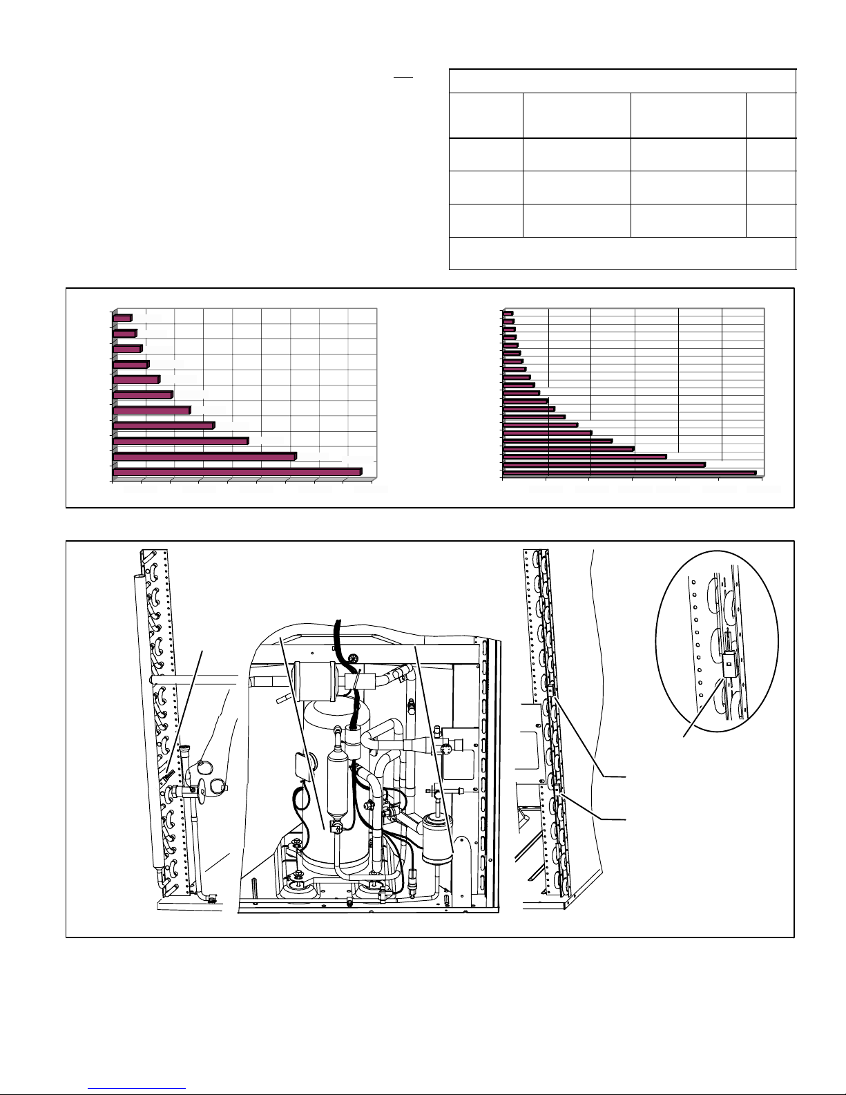
Table 9
Sensor Temperature / Resistance Range
Pins/W
ire
Color
(Black)
(Brown)
(Yellow)
Sensor
Temperature
Range °F (°C)
Resistance values
range (ohms)
Outdoor −35 (−37) to 120 (48) 280,000 to 3750 3 & 4
Coil −35 (−37) to 120 (48) 280,000 to 3750 5 & 6
Discharge (if
24 (−4) to 350 (176) 41,000 to 103 1 & 2
applicable)
Note: Sensor resistance decreases as sensed temperature increases
(see figure 20).
Ambient and Coil Sensor Discharge Sensor
100
TEMPERATURE (ºF)
5750
90
80
70
60
50
40
30
20
10
7450
9275
11775
15425
19975
26200
34375
46275
62700
0
10000 30000 50000 70000 90000 1000 2000 50004000 60003000
RESISTANCE (OHMS) RESISTANCE (OHMS)
85300
300
280
260
240
220
200
180
160
TEMPERATURE (ºF)
140
120
100
200
225
250
275
325
375
425
500
600
700
825
1000
Figure 20
Sensor Locations
DISCHARGE
LINE SENSOR
ALTERNATE
COIL
SENSOR
LOCATION.
AMBIENT SENSOR −
(Inside PVC tube) Extend
tip of plastic sensor just
outside of plastic sleeve.
1175
1400
1700
2025
2500
3000
3750
4650
5825
HPXA16−036 ALTERNATE
COIL SENSOR LOCATION
Figure 21
Page 17
COIL SENSOR DETAIL − Sensor
clips on the return bend as shown,
located on bends as follows:
HPXA16−024:
6th bend from top on outside
column.
HPXA16−036*, −048, −060:
5th bend from bottom on
outside column.
NOTE − DIAGRAMS ARE TYPICAL OF −024
AND −036 COIL; −048 & −060 COILS HAVE
MORE COIL SURFACE AREA AND
GREATER NUMBER OF BENDS.
* − −036 MODEL HAS ALTERNATE
LOCATION ON OPPOSITE SIDE AS SHOWN
TO THE LEFT
HPXA16 SERIES
Page 18

Defrost System Sensors
Ambient SensorThe ambient sensor considers out-
door temperatures below −35°F (−37°C) or above 120°F
(48°C) as a fault. If the ambient sensor is detected as being
open, shorted or out of the temperature range of the sensor, the board will not perform demand defrost operation.
The board will revert to time/temperature defrost operation
and will display the appropriate fault code. Heating and
cooling operation will be allowed in this fault condition.
Coil SensorThe coil temperature sensor considers outdoor temperatures below −35°F (−37°C) or above 120°F
(48°C) as a fault. If the coil temperature sensor is detected
as being open, shorted or out of the temperature range of
the sensor, the board will not perform demand or time/temperature defrost operation and will display the appropriate
fault code. Heating and cooling operation will be allowed in
this fault condition.
Discharge Line SensorIf the discharge line temperature exceeds a temperature of 300°F (148°C) during compressor operation, the board will de−energize the compressor contactor output (and the defrost output, if active). The
compressor will remain off until the discharge temperature
has dropped below 225°F (107°C) and the 5-minute anti−
short cycle delay has been satisfied. This sensor has two
fault and lockout codes:
1. If the board recognizes five high discharge line temperature faults during a single (Y1) compressor demand, it reverts to a lockout mode and displays the appropriate code. This code detects shorted sensor or
high discharge temperatures. (Code on board is Discharge Line Temperature Fault and Lockout").
2. If the board recognizes five temperature sensor range
faults during a single (Y1) compressor demand, it reverts to a lockout mode and displays the appropriate
code. The board detects open sensor or out-of-temperature sensor range. This fault is detected by allowing the unit to run for 90 seconds before checking sensor resistance. If the sensor resistance is not within
range after 90 seconds, the board will count one fault.
After 5 faults, the board will lockout. (Code on board
is Discharge Sensor Fault and Lockout").
The discharge line sensor, which covers a range of 150°F
(65°C) to 350°F (176°C), is designed to mount on a ½" refrigerant discharge line.
NOTE − Within a single room thermostat demand, if
5−strikes occur, the board will lockout the unit. Defrost
board 24 volt power R" must be cycled OFF" or the
TEST" pins on board must be shorted between 1 to 2 seconds to reset the board.
Second−Stage OperationIf the board receives a call for
second−stage compressor operation Y2" in heating or
cooling mode and the first-stage compressor output is active, the second-stage compressor solenoid output will be
energized.
NOTE − Figure 8 on page 5 shows the correct Y2 field wiring.
If first-stage compressor output is active in heating mode
and the outdoor ambient temperature is below the selected
compressor lock−in temperature, the second-stage compressor solenoid output will be energized without the Y2"
input. If the jumper is not connected to one of the temperature selection pins on P3 (40, 45, 50, 55°F), the default
lock−in temperature of 40°F (4.5°C) will be used.
The board de−energizes the second-stage compressor solenoid output immediately when the Y2" signal is removed
or the outdoor ambient temperature is 5°F above the selected compressor lock−in temperature, or the first-stage
compressor output is de−energized for any reason.
Defrost Temperature Termination Shunt (Jumper)
PinsThe defrost board selections are: 50, 70, 90, and
100°F (10, 21, 32 and 38°C). The shunt termination pin is
factory set at 50°F (10°C). If the temperature shunt is not
installed, the default termination temperature is 90°F
(32°C).
Delay Mode
The defrost board has a field−selectable function to reduce
occasional sounds that may occur while the unit is cycling
in and out of the defrost mode. When a jumper is installed
on the DELAY pins, the compressor will be cycled off for 30
seconds going in and out of the defrost mode. Units are
shipped with jumper installed on DELAY pins.
NOTE − The 30 second off cycle is NOT functional when
jumpering the TEST pins.
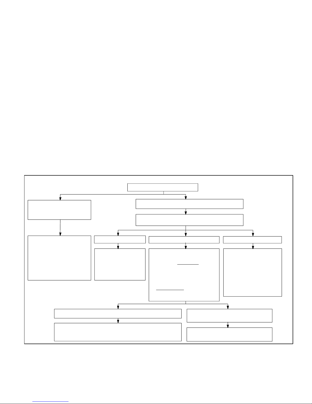
Operational Description
The defrost control board has three basic operational
modes: normal, defrost, and calibration.
Normal ModeThe demand defrost board monitors
the O line, to determine the system operating mode
(heat/cool), outdoor ambient temperature, coil temperature (outdoor coil) and compressor run time to determine when a defrost cycle is required.
Calibration ModeThe board is considered uncali-
brated when power is applied to the board, after cool
mode operation, or if the coil temperature exceeds the
termination temperature when it is in heat mode.
Calibration of the board occurs after a defrost cycle to
ensure that there is no ice on the coil. During calibration, the temperature of both the coil and the ambient
sensor are measured to establish the temperature differential which is required to allow a defrost cycle.
Defrost ModeThe following paragraphs provide a
detailed description of the defrost system operation.
Detailed Defrost System Operation
The demand defrost control board initiates a defrost cycle
based on either frost detection or time.
Frost DetectionIf the compressor runs longer than 34
minutes and the actual difference between the clear coil
and frosted coil temperatures exceeds the maximum difference allowed by the control, a defrost cycle will be initiated.
IMPORTANT − The demand defrost control board will allow
a greater accumulation of frost and will initiate fewer defrost cycles than a time/temperature defrost system.
504954M 08/06
Page 18
Page 19
TimeIf 6 hours of heating mode compressor run time
has elapsed since the last defrost cycle while the coil temperature remains below 35°F (2°C), the demand defrost
control will initiate a defrost cycle.
ActuationWhen the reversing valve is de−energized,
the Y1 circuit is energized, and the coil temperature is below 35°F (2°C), the board logs the compressor run time. If
the board is not calibrated, a defrost cycle will be initiated
after 34 minutes of heating mode compressor run time.
The control will attempt to self−calibrate after this (and all
other) defrost cycle(s).
Calibration success depends on stable system temperatures during the 20−minute calibration period. If the board
fails to calibrate, another defrost cycle will be initiated after
90 minutes of heating mode compressor run time. Once
the defrost board is calibrated, it initiates a demand defrost
cycle when the difference between the clear coil and
frosted coil temperatures exceeds the maximum difference allowed by the control OR after 6 hours of heating
mode compressor run time has been logged since the last
defrost cycle.
TerminationThe defrost cycle ends when the coil temperature exceeds the termination temperature or after 14
minutes of defrost operation. If the defrost is terminated by
the 14−minute timer, another defrost cycle will be initiated
after 34 minutes of run time.
Test Mode[NOTE − Coil sensor temperature must be
below 35ºF before the defrost board will initiate a
test" defrost.] When Y1 is energized and 24V power is
being applied to the board, a test cycle can be initiated by
placing the termination temperature jumper across the
Test" pins for 2 to 5 seconds. If the jumper remains across
the Test" pins longer than 5 seconds, the control will ignore the test pins and revert to normal operation. The
jumper will initiate one cycle per test.
Enter the TEST" mode by placing a shunt (jumper) across
the TEST" pins on the board after power−up. (The TEST"
pins are ignored and the test function is locked out if the
shunt is applied on the TEST" pins before power−up).
Board timings are reduced, the low−pressure switch is ignored and the board will clear any active lockout condition.
Each test pin shorting will result in one test event. For
each TEST" the shunt (jumper) must be removed for at
least 1 second and reapplied. Refer to flow chart (figure
22) for TEST" operation.
Note: The Y1 input must be active (ON) and the O" room
thermostat terminal into board must be inactive.
Defrost Board Diagnostics
See table 10 to determine defrost board operational conditions and to diagnose cause and solution to problems.
Short test pins for longer
than 1 second but less
than 2.0 seconds
Clear any short cycle lockout
and/or 5−strike fault lockout
function, if applicable. No
other functions will be
executed and unit will
continue in the mode it was
operating.
Test pin short REMAINS in place for more than 5 seconds Test pins short REMOVED before a
The unit will return to Heat mode uncalibrated with defrost
timer set for 34 minutes. No further test mode operation will
be executed until the test short is removed and re applied.
Test Mode
Y1 Active (0" line inactive)
Short test pins for more than 2.0 seconds
Clear any short cycle lockout or 5−strike fault
lockout function, if applicable.
If in COOLING Mode If in HEATING Mode If in DEFROST Mode
No further test mode
operation will be
executed until the test
short is removed and
reapplied.
The controller will check for
ambient and coil faults (open or
shorted). If a fault exists
will remain in Heat Mode and no
further test mode operation will
be executed until the test short
is removed and re applied. If
no fault exists
temperature is below 35ºF, the
unit will go into Defrost mode.
, the unit
and ambient
maximum of 5 seconds
The unit will remain in Defrost mode
until termination on time or temperature
The unit will terminate
defrost and enter Heat
Mode uncalibrated with
defrost timer set for 34
minute test. No further
test mode operation will
be executed until the test
short is removed and
reapplied.
Figure 22
Page 19
HPXA16 SERIES
Page 20
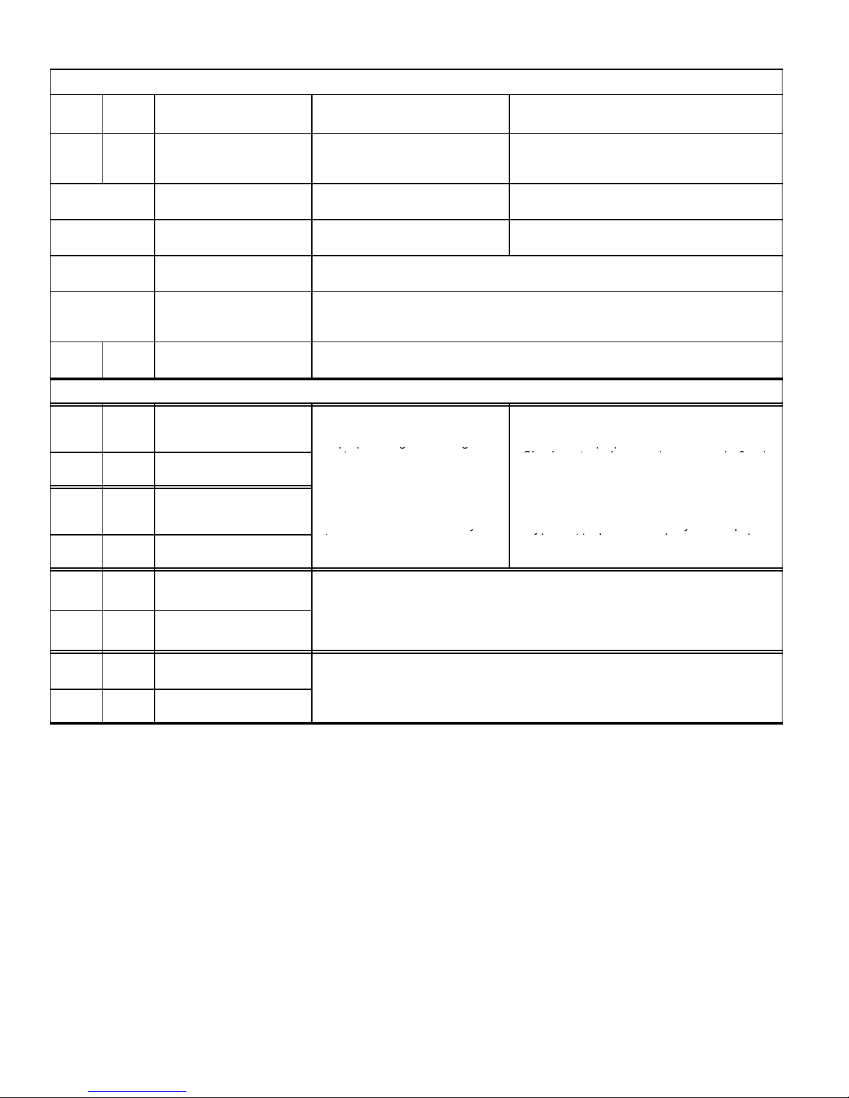
Table 10
pp g g
pp
installed
3
Check
d
y
yp
eration, the board will de−energize the compressor contactor output (and the defrost
Defrost Control Board Diagnostic LEDs
DS2
Green
OFF OFF Power problem No power (24V) to board termi-
DS1
Red
Condition/Code Possible Cause(s) Solution
1
Check control transformer power (24V).
nals R & C or board failure.
2
If power is available to board and LED(s) do
not light, replace board.
Simultaneous
SLOW Flash
Alternating
SLOW Flash
Simultaneous
FAST Flash
Alternating
FAST Flash
Normal operation Unit operating normally or in
None required.
standby mode.
5−minute anti−short cycle
delay
Initial power up, safety trip, end of
room thermostat demand.
None required (Jumper TEST pins to override)
Ambient Sensor Problem Sensor being detected open or shorted or out of temperature range. Board will re-
vert to time/temperature defrost operation. (System will still heat or cool).
Coil Sensor Problem Sensor being detected open or shorted or out of temperature range. Board will not
perform demand or time/temperature defrost operation. (System will still heat or
cool).
ON ON Circuit Board Failure Indicates that board has internal component failure. Cycle 24 volt power to board. If
code does not clear, replace board.
FAULT & LOCKOUT CODES (Each fault adds 1 strike to that code’s counter; 5 strikes per code = LOCKOUT)
OFF SLOW
Low Pressure Fault
Flash
OFF ON Low Pressure LOCKOUT
SLOW
OFF High Pressure Fault
Flash
ON OFF High Pressure LOCKOUT
1
Restricted air flow over indoor or
outdoor coil.
2
Improper refrigerant charge in
system.
3
Improper metering device
or incorrect operation
of metering device.
4
Incorrect or improper sensor
location or connection to system.
1
Remove any blockages or restrictions from
coils and/or fans. Check indoor and outdoor
fan motor for proper current draws.
2
Check system charge using approach & subcooling temperatures.
3
4
system operating pressures an
compare to unit charging charts.
Make sure all pressure switches and sensors
have secure connections to system to prevent
refrigerant leaks or errors in pressure and
temperature measurements.
SLOW
ON Discharge Line Tempera-
Flash
FAST
ON Discharge Line Tempera-
Flash
OFF Fast
Flash
Fast
OFF Discharge Sensor
Flash
This code detects shorted sensor or high discharge temperatures. If the discharge
ture Fault
line temperature exceeds a temperature of 300ºF (148ºC) during compressor op-
−
output if active). The compressor will remain off until the discharge temperature has
ture LOCKOUT
dropped below 225ºF (107ºC).
Discharge Sensor Fault The board detects open sensor or out of temperature sensor range. This fault is
detected by allowing the unit to run for 90 seconds before checking sensor resistance. If the sensor resistance is not within range after 90 seconds, the board will
LOCKOUT
count one fault. After 5 faults, the board will lockout.
504954M 08/06
Page 20
Page 21
Maintenance
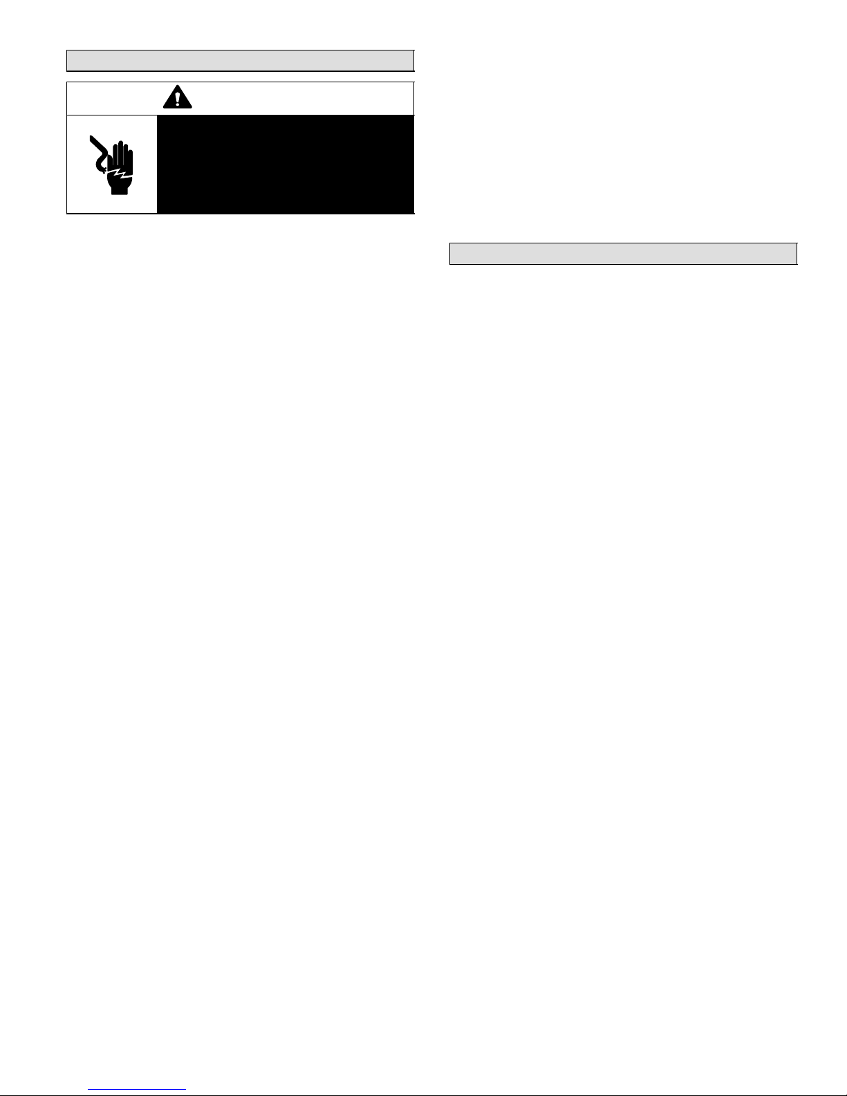
WARNING
Electric shock hazard. Can cause injury or death. Before attempting to perform any service or maintenance, turn
the electrical power to unit OFF at disconnect switch(es). Unit may have
multiple power supplies.
Before the start of each heating and cooling season, the
following service checks should be performed by a qualified service technician. First, turn off electrical power to the
unit prior to performing unit maintenance.
Inspect and clean the outdoor and indoor coils. The
outdoor coil may be flushed with a water hose.
NOTE − It may be necessary to flush the outdoor coil
more frequently if it is exposed to substances which
are corrosive or which block airflow across the coil
(e.g., pet urine, cottonwood seeds, etc.)
Visually inspect the refrigerant lines and coils for leaks.
Check wiring for loose connections.
Check voltage at the indoor and outdoor units (with
units operating).
Check the amperage draw at the outdoor fan motor,
compressor, and indoor blower motor. Values should
be compared with those given on unit nameplate.
Check, clean (or replace) indoor unit filters.
Check the refrigerant charge and gauge the system
pressures.
Check the condensate drain line for free and unob-
structed flow; clean, if necessary.
Adjust blower speed for cooling. Measure the pressure
drop over the coil to determine the correct blower CFM.
Refer to the unit information service manual for pressure
drop tables and procedure.
Check drive belt for wear and proper tension.
NOTE − If owner reports insufficient cooling, the unit
should be gauged and refrigerant charge checked. Refer to section on refrigerant charging in this instruction.
Optional Accessories
Refer to the Engineering Handbook for optional accessories that may apply to this unit. The following may or may
not apply:
Loss of charge kit
High pressure switch kit
Compressor monitor
Compressor crankcase heater
Hail guards
Mounting bases
Timed-off control
Stand−off Kit
Sound cover
Low ambient kit
Monitor kit
Dave Lennox SignatureStat
Room Thermostat
Page 21
HPXA16 SERIES
Page 22
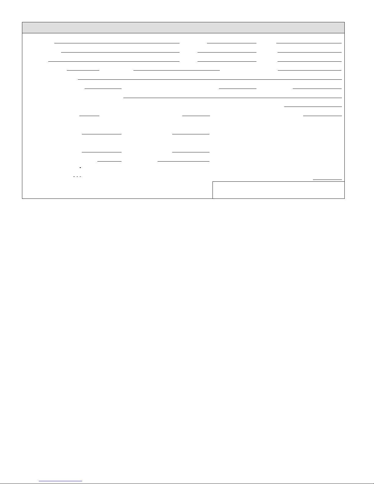
Start−Up and Performance Check List
Job Name Job no. Date
Job Location City State
Installer City State
Unit Model No. Serial No. Service Technician
Nameplate Voltage
Rated Load Ampacity Compressor Amperage: 1st Stage 2nd Stage:
Maximum Fuse or Circuit Breaker
Electrical Connections Tight? Indoor Filter clean? Supply Voltage (Unit Off)
Indoor Blower RPM S.P. Drop Over Indoor (Dry) Outdoor Coil Entering Air Temp.
COOLING (2ND STAGE)
Liquid Line Pressure: Vapor Pressure: Refrigerant Charge Checked?
HEATING (2ND STAGE)
Liquid Line Pressure: Vapor Pressure: Refrigerant Charge Checked?
Vapor Pressure; 1st Stage: 2nd Stage:
Refrigerant Lines: Leak Checked? Properly Insulated? Outdoor Fan Checked?
Service Valves: Fully Opened? Caps Tight? Voltage With Compressor Operating
SEQUENCE OF OPERATION
Heating Correct? Cooling Correct?
Calibrated? Properly Set? Level?
THERMOSTAT
504954M 08/06
Page 22
Page 23
2006 Lennox Industries Inc.
Dallas, Texas, USA
Homeowner Information − Maintenance
In order to ensure peak performance, your system must be
properly maintained. Clogged filters and blocked airflow
prevent your unit from operating at its most efficient level.
1. Ask your Lennox dealer to show you where your indoor
unit’s filter is located. It will be either at the indoor unit
(installed internal or external to the cabinet) or behind
a return air grille in the wall or ceiling. Check the filter
monthly and clean or replace it as needed.
2. Disposable filters should be replaced with a filter of the
same type and size.
NOTE − If you are unsure about the filter you need for
your system, call your Lennox dealer for assistance.
IMPORTANT
Turn off electrical power to the unit at the
disconnect switch before performing any
maintenance. The unit may have multiple power
supplies.
3. Many indoor units are equipped with reusable foam filters. These filters can be cleaned with a mild soap and
water solution. Rinse the filter thoroughly and let it dry
completely before it is returned to the unit or grille.
NOTE − The filter and all access panels must be in
place any time the unit is in operation.
4. Some systems are equipped with an electronic air
cleaner, designed to remove the majority of airborne
particles from the air passing through the cleaner. If
your system is so equipped, ask your dealer for maintenance instructions.
5. Inspect and clean indoor coil. The indoor evaporator
coil is equipped with a drain pan to collect condensate
formed as your system removes humidity from the inside air. Have your dealer show you the location of the
drain line and how to check for obstructions. (This
would also apply to an auxiliary drain, if installed.)
HPXA16
IMPORTANT
Sprinklers and soaker hoses should not be installed
where they could cause prolonged exposure to the
outdoor unit by treated water. Prolonged exposure
of the unit to treated water (i.e., sprinkler systems,
soakers, waste water, etc) will corrode the surface of
steel and aluminum parts and diminish performance
and longevity of the unit.
Heat Pump Operation
Your new Lennox heat pump has several characteristics
that you should be aware of:
Heat pumps satisfy heating demand by delivering
large amounts of warm air into the living space. This
is quite different from gas- or oil-fired furnaces or an
electric furnace which deliver lower volumes of considerably hotter air to heat the space.
Do not be alarmed if you notice frost on the outdoor coil
in the winter months. Frost develops on the outdoor
coil during the heating cycle when temperatures are
below 45°F (7°C). An electronic control activates a de-
frost cycle lasting 5 to 15 minutes at preset intervals
to clear the outdoor coil of the frost.
During the defrost cycle, you may notice steam rising
from the outdoor unit. This is a normal occurrence. The
thermostat may engage auxiliary heat during the defrost cycle to satisfy a heating demand; however, the
unit will return to normal operation at the conclusion of
the defrost cycle.
In case of extended power outage...
The heat pump is equipped with a compressor crankcase
heater which protects the compressor from refrigerant
slugging" during cold weather operation.
If power to your unit has been interrupted for several hours
or more, set the room thermostat selector to the Emergency Heat" setting to obtain temporary heat without the
risk of serious damage to the heat pump.
In Emergency Heat mode, all heating demand is satisfied
by auxiliary heat; heat pump operation is locked out. After a
six-hour compressor crankcase warm-up" period, the
thermostat can be switched to the Heat" setting and normal heat pump operation may resume.
Page 23
HPXA16 SERIES
Page 24

Thermostat Operation − Thermostat Operation
Though your thermostat may vary somewhat from the description below, its operation will be similar.
Temperature Setting Levers
Most heat pump thermostats have two temperature selector levers: one for heating and one for cooling. Set the levers or dials to the desired temperature setpoints for both
heating and cooling. Avoid frequent temperature adjustment; turning the unit off and back on before pressures
equalize puts stress on the unit compressor.
Fan Switch
In AUTO or INT (intermittent) mode, the blower operates
only when the thermostat calls for heating or cooling. This
mode is generally preferred when humidity control is a
priority. The ON or CONT mode provides continuous indoor blower operation, regardless of whether the compressor or auxiliary heat are operating. This mode is required when constant air circulation or filtering is desired.
System Switch
Set the system switch for heating, cooling or auto operation. The auto mode allows the heat pump to automatically
switch from heating mode to cooling mode to maintain predetermined comfort settings. Many heat pump thermostats are also equipped with an emergency heat mode
which locks out heat pump operation and provides temporary heat supplied by the auxiliary heat.
Indicating Light
Most heat pump thermostats have an amber light which in-
dicates when the heat pump is operating in the emergency
heat mode.
Temperature Indicator
The temperature indicator displays the actual room temperature.
Programmable Thermostats
Your Lennox system may be controlled by a programmable thermostat. These thermostats provide the added
feature of programmable time-of-day setpoints for both
heating and cooling. Refer to the user’s information manual provided with your particular thermostat for operation
details.
Preservice Check
If your system fails to operate, check the following before
calling for service:
Check to see that all electrical disconnect switches are
ON.
Make sure the room thermostat temperature selector
is properly set.
Make sure the room thermostat system switch is prop-
erly set.
Replace any blown fuses, or reset circuit breakers.
Make sure unit access panels are in place.
Make sure air filter is clean.
Locate unit model number and have it handy before
calling.
504954M 08/06
Page 24
 Loading...