

Lennox HPXA12 Series, HPXA12-018, HPXA12-024, HPXA12-030, HPXA12-036 Unit Information
...
Corp. 0208−L3
Service Literature
Revised 09−2004
HPXA12 SERIES UNITS
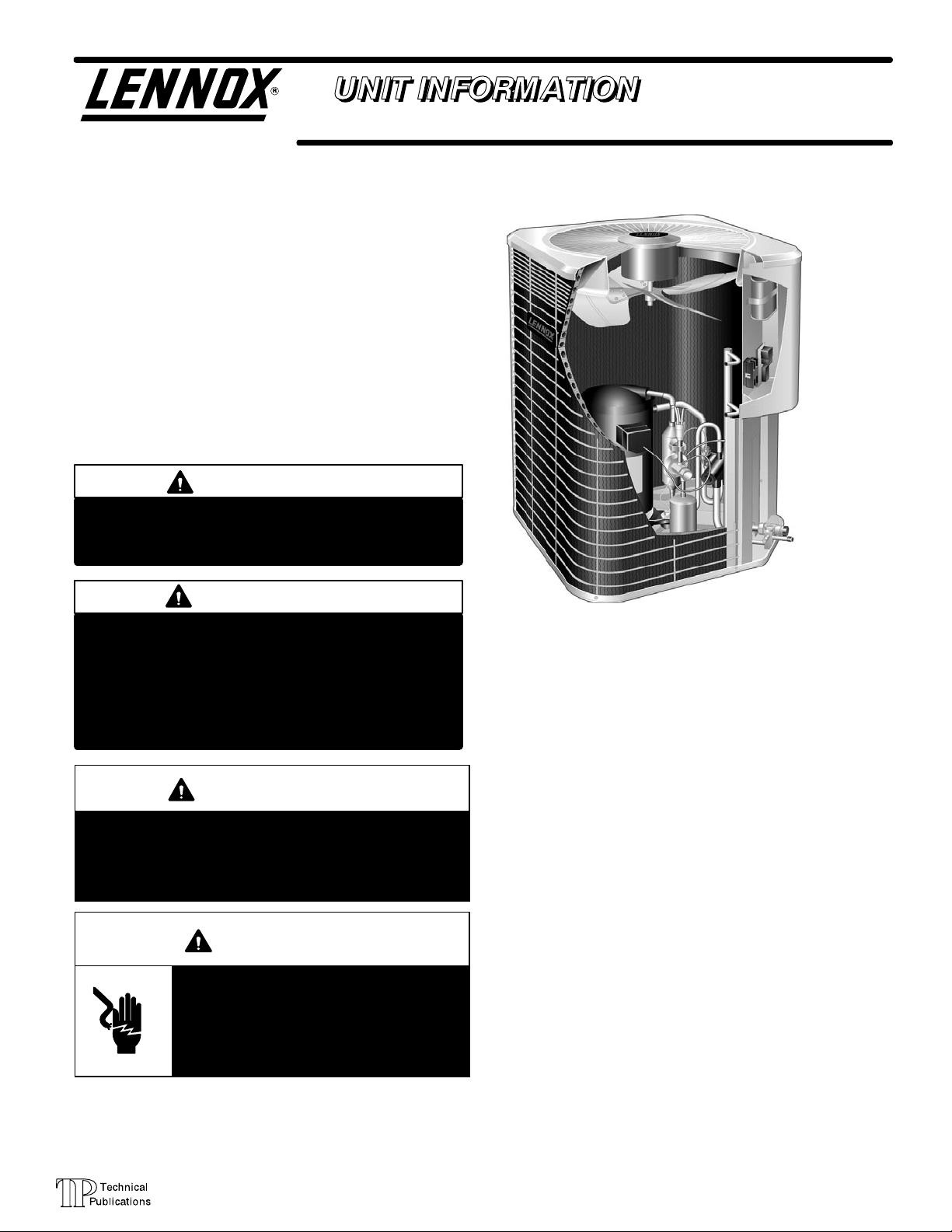
The HPXA12 is a high efficiency residential split−system
heat pump unit, which features a scroll compressor and
R410A refrigerant. HPXA12 units are available in sizes
ranging from 1 1/2 through 5 tons. The series is designed
for use with an expansion valve only (approved for use with
R410A) in the indoor unit.This manual is divided into sections which discuss the major components, refrigerant system, charging procedure, maintenance and operation sequence.
Information contained in this manual is intended for use by
qualified service technicians only. All specifications are
subject to change.
IMPORTANT
Operating pressures of this R410A unit are higher
than pressures in R22 units. Always use service
equipment rated for R410A.
HPXA12
WARNING
Warranty will be voided if covered equipment is removed from original installation site. Warranty will
not cover damage or defect resulting from:
Flood, wind, lightning, or installation and operation in a corrosive atmosphere (chlorine, fluorine,
salt, recycled waste water, urine, fertilizers, or other damaging chemicals).
WARNING
Improper installation, adjustment, alteration, service
or maintenance can cause property damage, personal injury or loss of life. Installation and service must
be performed by a qualified installer or service
agency.
WARNING
Electric shock hazard. Can cause injury
or death. Before attempting to perform
any service or maintenance, turn the
electrical power to unit OFF at disconnect switch(es). Unit may have multiple
power supplies.
TABLE OF CONTENTS
General 1. . . . . . . . . . . . . . . . . . . . . . . . . . . . . . . . . . . . . .
Specifications / Electrical 2. . . . . . . . . . . . . . . . . . . . . . . .
I Unit Information 5. . . . . . . . . . . . . . . . . . . . . . . . . . . . . .
II Unit Components 5. . . . . . . . . . . . . . . . . . . . . . . . . . . . .
III Refrigerant System 13. . . . . . . . . . . . . . . . . . . . . . . . . .
IV Charging 15. . . . . . . . . . . . . . . . . . . . . . . . . . . . . . . . . . .
V Service and Recovery 19. . . . . . . . . . . . . . . . . . . . . . . .
VI Maintenance 19. . . . . . . . . . . . . . . . . . . . . . . . . . . . . . . .
VII Wiring Diagram and Operating Sequence 20. . . . . .
Page 1
©2002 Lennox Industries Inc.
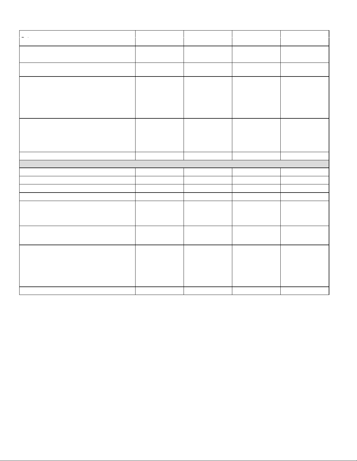
SPECIFICATIONS single phase
Fan
Net face area
Kit
M
General
Data
Connections
(sweat)
Refrigerant (R410A) furnished 7 lbs. 5 oz. (3.31 kg) 6 lbs. 12 oz. (3.06
Outdoor
Coil
Fan
Outdoor
Coil
Shipping Data lbs. (kg) 1 package 160 (73) 160 (73) 176 (80) 181 (82)
Diameter − in. (mm) & no. of blades
Net face area
sq. ft. (m2)
Tube diameter − in. (mm) & no. of rows
Nominal Tonnage (kW) 1.5 (5.3) 2 (7.0) 2.5 (8.8) 3 (10.6)
Liquid line o.d. − in. (mm) 3/8 (9.5) 3/8 (9.5) 3/8 (9.5) 3/8 (9.5)
Vapor line o.d. − in. (mm) 3/4 (19.1) 3/4 (19.1) 3/4 (19.1) 7/8 (22.2)
Model No. HPXA12−018 HPXA12−024 HPXA12−030 HPXA12−036
Motor hp (W)
Cfm (L/s)
Rpm
Watts
Outer coil
Inner coil
Fins per inch (m)
18 (457) − 3
1/6 (124)
2500 (1180)
1100
200
15.21 (1.41)
5.44 (0.51)
5/16 (8) − 1.37
18 (709)
kg)
18 (457) − 3 18 (457) − 4 18 (457) − 4
1/6 (124) 1/6 (124) 1/6 (124)
2500 (1180) 2450 (1155) 2450 (1155)
1100 1100 1100
200 200 200
15.21 (1.41) 15.21 (1.41) 15.21 (1.41)
5.44 (0.51) 14.50 (1.35) 14.50 (1.35)
5/16 (8) − 1.37 5/16 (8) − 2 5/16 (8) − 2
18 (709) 18 (709) 18 (709)
7 lbs. 12 oz. (3.51
kg)
8 lbs. 15 oz. (4.1 kg)
OPTIONAL ACCESSORIES − MUST BE ORDERED EXTRA
Compressor Monitor (Canada Only) 45F08 45F08 45F08 45F08
Hail Guards 17L73 17L73 17L73 17L73
Mild Ambient Kit (LB-101122) 32M08 32M08 32M08 32M08
Monitor Kit (Canada Only) 76F53 76F53 76F53 76F53
Outdoor
Thermostat
Kit
Plastic
ounting
Base
Refrigerant
Line Set
Unit Stand-Off Kit 94J45 94J45 94J45 94J45
Refer to National or Canadian Electrical Code manual to determine wire, fuse and disconnect size requirements.
Refrigerant charge is sufficient for 15 ft. (4.5 m) length line set.
NOTE − Extremes of operating range are plus 10% and minus 5% of line voltage
Part No. − Catalog Number MB2-S (69J06) MB2-S (69J06) MB2-S (69J06) MB2-S (69J06)
Suction/Vapor Line o.d. − in. (mm) 3/4 (19) 3/4 (19) 3/4 (19) 7/8 (22.2)
Liquid Line o.d. − in. (mm) 3/8 (9.5) 3/8 (9.5) 3/8 (9.5) 3/8 (9.5)
Thermostat 56A87 56A87 56A87 56A87
Mounting Box − US 31461 31461 31461 31461
Canada 33A29 33A29 33A29 33A29
Net Weight 6 lbs. (3 kg) 6 lbs. (3 kg) 6 lbs. (3 kg) 6 lbs. (3 kg)
30 ft. (9 m) length L15−41−30 L15−41−30 L15−41−30 L15−65−30
40 ft. (12 m) length L15−41−40 L15−41−40 L15−41−40 L15−65−40
50 ft. (15 m) length L15−41−50 L15−41−50 L15−41−50 L15−65−50
Page 2

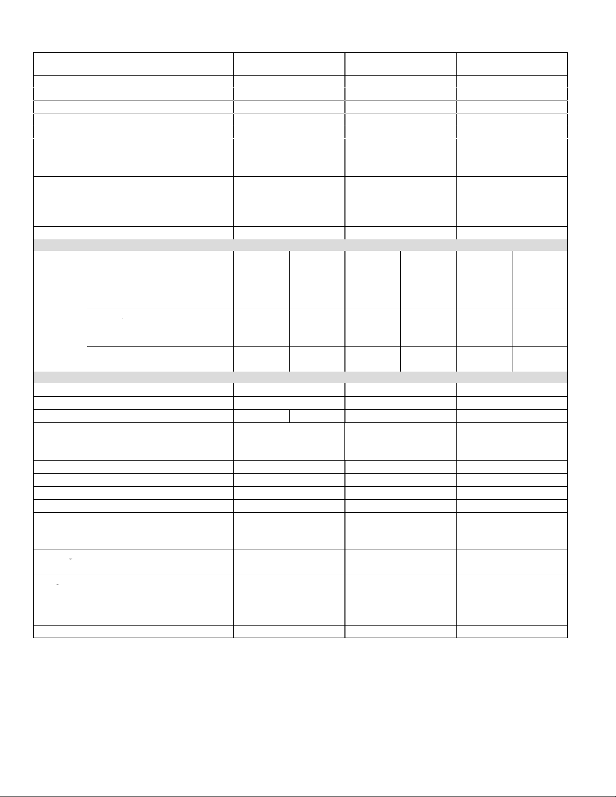
SPECIFICATIONS single phase Cont.
Fan
Net face area
Kit
M
g
p
General
Data
Connections
(sweat)
Refrigerant (R410A) furnished 9 lb. 2 oz. (4.13 kg) 11 lbs. 5 oz. (5.12 kg) 11 lbs. 3 oz. (5.06 kg)
Outdoor
Coil
Outdoor
Coil
Shipping Data lbs. (kg) 1 package 190 (86) 244 (111) 244 (111)
Diameter − in. (mm) & no. of blades 18 (457) − 4 22 (559) − 4 22 (559) − 4
Net face area
sq. ft. (m2)
Tube diameter − in. (mm) & no. of rows 5/16 (8) − 2 5/16 (8) − 2 5/16 (8) − 2
Nominal Tonnage (kW) 3.5 (12.3) 4 (14.1) 5 (17.6)
Liquid line o.d. − in. (mm) 3/8 (9.5) 3/8 (9.5) 3/8 (9.5)
Vapor line o.d. − in. (mm) 7/8 (22.2) 7/8 (22.2) 1−1/8 (28.6)
Model No. HPXA12−042 HPXA12−048 HPXA12−060
Motor hp (W) 1/3 (249) 1/3 (249) 1/3 (249)
Cfm (L/s) 2930 (1385) 3890 (1835) 3890 (1835)
Rpm 1100 1085 1085
Watts 310 375 375
Outer coil 15.21 (1.41) 21.11 (1.96) 21.11 (1.96)
Inner coil 14.50 (1.35) 20.31 (1.89) 20.31 (1.89)
Fins per inch (m) 22 (860) 22 (860) 22 (860)
OPTIONAL ACCESSORIES − MUST BE ORDERED EXTRA
Compressor Monitor (Canada Only) 45F08 45F08 45F08
Hail Guards 17L73 17L74 17L74
Mild Ambient Kit (LB-101122) 32M08 32M08 32M08
Monitor Kit (Canada Only) 76F53 76F53 76F53
Outdoor
Thermostat
Plastic
ounting
Base
Refrigerant
Line Set
Unit Stand-Off Kit 94J45 94J45 94J45
Refer to National or Canadian Electrical Code manual to determine wire, fuse and disconnect size requirements.
Refrigerant charge is sufficient for 20 ft. (6.1 m) length line set.
NOTE − Extremes of operating range are plus 10% and minus 5% of line voltage
Part No. − Catalog Number MB2-S (69J06) MB2-L (69J07) MB2-L (69J07)
Suction/Vapor Line o.d. − in. (mm) 7/8 (22.2) 7/8 (22.2) 1−1/8 (28.5)
Liquid Line o.d. − in. (mm) 3/8 (9.5) 3/8 (9.5) 3/8 (9.5)
Thermostat 56A87 56A87 56A87
Mounting Box − US 31461 31461 31461
Canada 33A29 33A29 33A29
Net Weight 6 lbs. (3 kg) 15 lbs. (7 kg) 15 lbs. (7 kg)
30 ft. (9 m) length L15−65−30 L15−65−30 Field Fabricate
40 ft. (12 m) length L15−65−40 L15−65−40 Field Fabricate
50 ft. (15 m) length L15−65−50 L15−65−50 Field Fabricate
ELECTRICAL DATA
Model No. HPXA12−018 HPXA12−024 HPXA12−030 HPXA12−036 HPXA12−042 HPXA12−048 HPXA12−060
Line voltage data − 60 hz − 1 phase 208/230v 208/230v 208/230v 208/230v 208/230v 208/230v 208/230v
Recommended maximum fuse or
circuit breaker size (amps)
{Minimum circuit ampacity 14.0 18.0 20.0 20.4 25.9 30.8 36.4
Compressor
Outdoor Coil
Fan Motor
Refer to National or Canadian Electrical Code manual to determine wire, fuse and disconnect size requirements.
NOTE Extremes of operating range are plus 10% and minus 5% of line voltage.
Rated load amps 10.3 13.5 15.1 15.4 19.2 23.1 27.6
Power factor .98 .98 .98 .98 .99 .99 .99
Locked rotor amps 51 61 72.5 83 104 134 158
Full load amps 1.1 1.1 1.1 1.1 1.9 1.9 1.9
Locked rotor amps 1.9 1.9 1.9 1.9 4.1 4.1 4.1
20 30 35 35 45 50 60
Page 3
SPECIFICATIONS three phase
Fan
Net face area
p
Kit
g
g
General
Data
Connections
(sweat)
1
Refrigerant (R410A) furnished 8 lbs. 15 oz. (4.1 kg) 11 lbs. 5 oz. (5.1 kg) 11 lbs. 3 oz. (5.1 kg)
Outdoor
Diameter − in. (mm) & no. of blades 18 (457) − 4 22 (559) − 4 22 (559) − 4
Nominal Tonnage (kW) 3 (10.6) 4 (14.1) 5 (17.6)
Liquid line o.d. − in. (mm) 3/8 (9.5) 3/8 (9.5) 3/8 (9.5)
Vapor line o.d. − in. (mm) 7/8 (22.2) 7/8 (22.2) 1−1/8 (28.6)
Coil
Outdoor
Coil
Net face area
sq. ft. (m2)
Tube diameter − in. (mm) & no. of rows 5/16 (8) − 2 5/16 (8) − 2 5/16 (8) − 2
Shipping Data 1 package − lbs. (kg) 181 (82) 244 (111) 244 (111)
ELECTRICAL DATA
Line voltage data − 60 hz − 3 phase 208/230V 460V 208/230V 460V 208/230V 460V
2
Maximum overcurrent protection (amps) 25 10 35 15 40 20
3
Minimum circuit ampacity 15.4 6.9 21.9 9.8 24.5 12.2
Compressor
Locked Rotor amps 77 35 91 46 137 62
Outdoor Coil
Fan Motor
Locked Rotor Amps 2.3 1 4.1 2.1 4.1 2.1
OPTIONAL ACCESSORIES − MUST BE ORDERED EXTRA
Compressor Low Ambient Cut−Off 45F08 45F08 45F08
Compressor Sound Cover 69J03 69J03 69J03
Compressor Crankcase Heater 67K90 67K89 Factory Installed Factory Installed
Freezestat
Hail Guards 17L73 17L74 17L74
Low Ambient Kit 54M89 54M89 54M89
Mild Weather Kit 33M07 33M07 33M07
Monitor Kit − Service Light 76F53 76F53 76F53
Outdoor
Thermostat
Kit
Mounting
Base
Refrigerant
Line Set
Unit Stand-Off Kit 94J45 94J45 94J45
NOTE − Extremes of operating range are plus 10% and minus 5% of line voltage.
1
Refrigerant charge is sufficient for 15 ft. (4.6 m) length line set.
2
HACR tyoe circuit breaker or fuse.
3
Refer to National or Canadian Electrical Code manual to determine wire, fuse and disconnect size requirements.
Mounting Box − US 31461 31461 31461
15 ft. (4.6 m) length L15−65−15 L15−65−15 Field Fabricate
40 ft. (12 m) length L15−65−40 L15−65−40 Field Fabricate
50 ft. (15 m) length L15−65−50 L15−65−50 Field Fabricate
Model No. HPXA12−036 HPXA12−048 HPXA12−060
Motor hp (W) 1/6 (124) 1/3 (249) 1/3 (249)
Cfm (L/s) 2450 (1155) 3890 (1835) 3890 (1835)
Rpm 1100 1085 1085
Watts 200 375 375
Outer coil 15.21 (1.41) 21.11 (1.96) 21.11 (1.96)
Inner coil 14.50 (1.35) 20.31 (1.89) 20.31 (1.89)
Fins per inch (m) 18 (709) 22 (860) 22 (860)
Model No. HPXA12−036
Rated load amps
−233
11.5 5.1 16 7.1 18.1 9
HPXA12−036
−463
HPXA12−048
−233
HPXA12−048
−463
HPXA12−060
−233
HPXA12−060
Power Factor .98 .98 .99 .99 .99 .99
Full load amps
1 .55 1.9 .9 1.9 .9
3/8 in. tubing 93G35 93G35 93G35
1/2 in. tubing 39H29 39H29 39H29
5/8 in. tubing 50A93 50A93 50A93
Thermostat 56A87 56A87 56A87
Canada 33A09 33A09 33A09
Model (Catalog) No. MB2-S (69J06) MB2-L (69J07) MB2-L (69J07)
Net Weight 6 lbs. (3 kg) 15 lbs. (7 kg) 15 lbs. (7 kg)
30 ft. (9 m) length L15−65−30 L15−65−30 Field Fabricate
−463
Page 4
I − UNIT INFORMATION
ELECTROSTATIC DISCHARGE (ESD)
Precautions and Procedures
CAUTION
Electrostatic discharge can affect electronic
components. Take precautions during unit installation and service to protect the unit’s electronic
controls. Precautions will help to avoid control
exposure to electrostatic discharge by putting
the unit, the control and the technician at the
same electrostatic potential. Neutralize electrostatic charge by touching hand and all tools on an
unpainted unit surface before performing any
service procedure.
All major components (indoor blower and coil) must be
matched according to Lennox recommendations for the
compressor to be covered under warranty. Refer to the Engineering Handbook for approved system matchups. A
missapplied system will cause erratic operation and can result in early compressor failure.
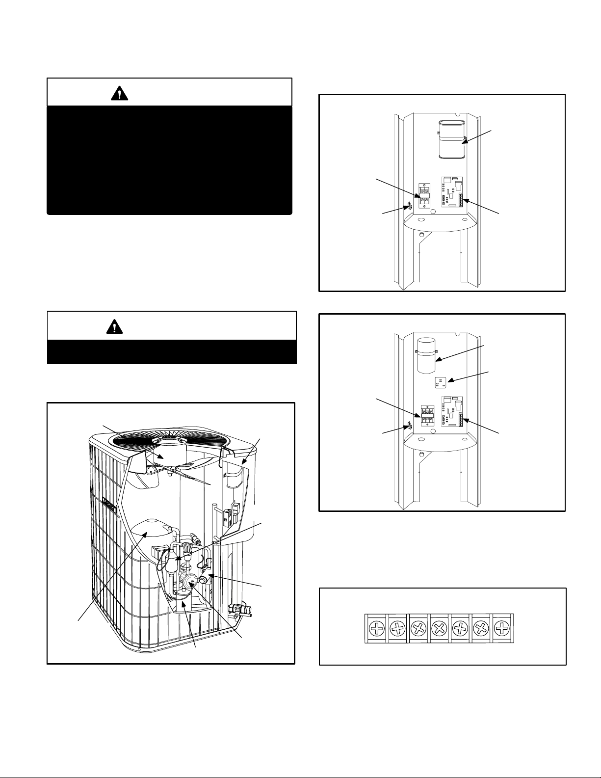
A − Control Box (Figures 2 and 3)
HPXA12 units are not equipped with a 24V transformer. All
24 VAC controls are powered by the indoor unit. Refer to
wiring diagram.
SINGLE PHASE UNIT CONTROL BOX
DUAL CAPACITOR
(C12)
COMPRESSOR
CONTACTOR
(K1)
DEFROST
GROUNDING
LUG
FIGURE 2
CONTROL
(A108)
IMPORTANT
This unit must be matched with an indoor coil as
specified in Lennox’ Engineering Handbook.
II − UNIT COMPONENTS
Unit components are illustrated in figure 1.
OUTDOOR
FAN/MOTOR
HPXA12 UNIT COMPONENTS
CONTROL
BOX
SUCTION
MUFFLER
REVERSING
VALV E
THREE PHASE UNIT CONTROL BOX
RUN CAPACITOR
(C1)
OUTDOOR FAN
RELAY (K10)
460 VOLTAGE
COMPRESSOR
CONTACTOR
(K1)
GROUNDING
LUG
ONLY
DEFROST
CONTROL
(A108)
FIGURE 3
Electrical openings are provided under the control box cover. Field thermostat wiring is made to a 24V terminal strip
located on the defrost control board located in the control
box. See figure 4.
24V THERMOSTAT TERMINAL STRIP
COMPRESSOR
BI-FLOW
FILTER DRIER
FIGURE 1
CHECK/EXPANSION
VALV E
Page 5
Y2
CRW1OY1L
FIGURE 4
1 − Compressor Contactor K1
The compressor is energized by a contactor located in the
control box. See figure 2. Single−pole contactors are used
in single−phase HPXA12 series units and three pole contactors are used in HPXA12 three−phase units. K1 is energized through the control board by the indoor thermostat
terminal Y1 (24V) when thermostat demand is present.
DANGER
Electric Shock Hazard.
May cause injury or death.
Line voltage is present at all components when unit is not in operation on
units with single pole contactors.
Disconnect all remote electrical power
supplies before opening unit panel.
Unit may have multiple power supplies.
2 − Outdoor Fan Relay K10 (460V units only)
Outdoor fan relay K10, used in 460V units only, is a SPST
normally open relay. K10 is energized by contactor K1
which in turn energizes outdoor fan B4 in response to thermostat demand.
3 − Run Capacitor C1 (three phase only)
The fan in all three−phase units uses a single−phase permanent split capacitor motor. A single capacitor C1 is used for
the fan motor. C1 is located inside the control box. See figure 3. Fan motor nameplate will have capacitor ratings.
The demand defrost board uses basic differential temperature means to detect degradation of system performance
due to ice build−up on the outdoor coil. Further, the controller uses self−calibrating" principles to calibrate itself when
the system starts and after each time the system defrosts.
The control board has defrost relays, anti−short cycle
timed−off control, pressure switch/safety control, 3−strike
lockout circuit, field test pins, ambient and coil temperature sensors, field selectable termination temperature and
a field low voltage connection terminal strip.
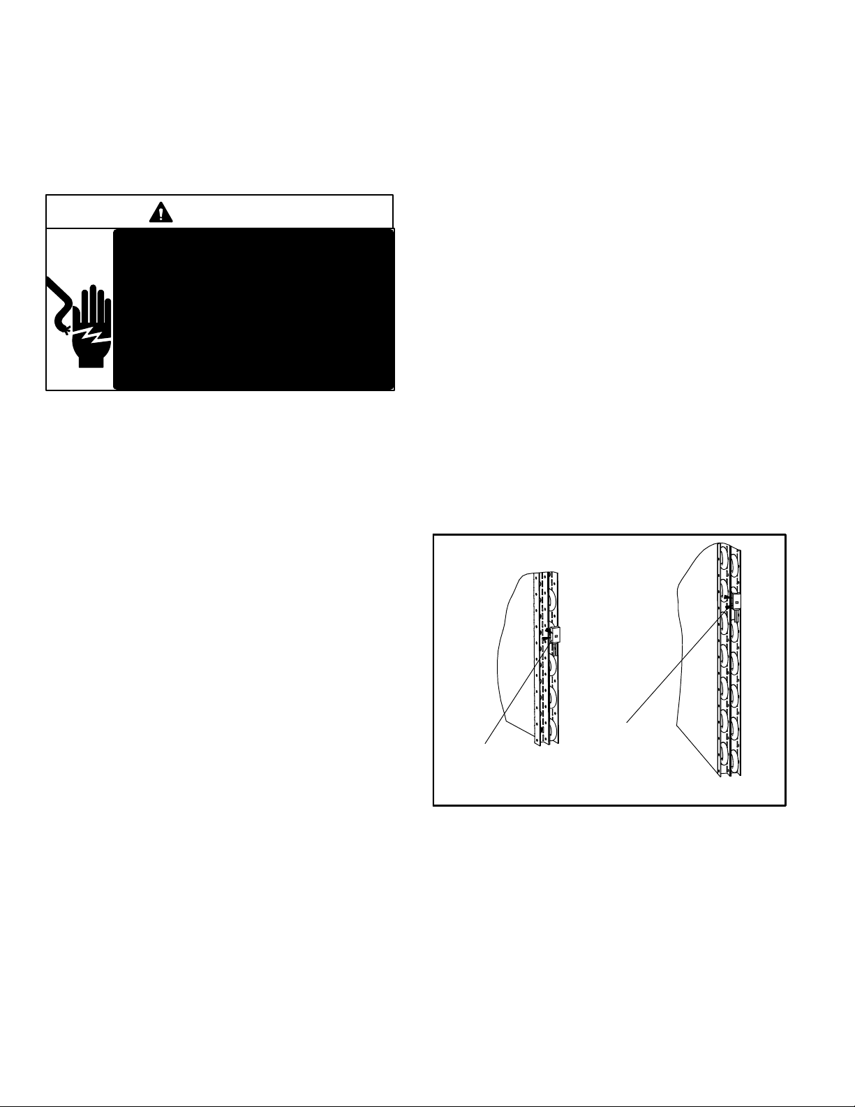
The control monitors ambient temperature, outdoor coil
temperature and total run time to determine when a defrost cycle is required. Two temperature probes are permanently attached to the control. The coil temperature
probe is designed with a spring clip to allow mounting to
the outside coil tubing. The location of the coil sensor is important for proper defrost operation. On HPXA12−018 &
−024 the sensor should located on the 4th hairpin bend
from the bottom. HPXA12−030 through −060 units the sensor should located on the 6th hairpin bend from the bottom. See figure 5.
NOTE − The logic of the Demand Defrost Board provides
accurate performance measurements of the system as
FROST accumulates on the outdoor coil. This will translate
into longer running time in the heating mode with FROST
accumulations on the outdoor coil before the board initiates
any defrost cycles.
COIL SENSOR LOCATION
4 − Dual Capacitor C12
The compressor and fan in single phase HPXA12 series units
use permanent split capacitor motors. The capacitor is located
inside the unit control box (see figure 2). A single dual" capacitor (C12) is used for both the fan motor and the compressor
(see unit wiring diagram). The fan side and the compressor
side of the capacitor have different MFD ratings. See side of
capacitor for ratings.
5 − Demand Defrost System
Boards 60L3901, 46M8201, 56M8501
The HPXA12 will be equipped with one of three model defrost boards. Differences are minimal:
Three strike lock out feature (60L3901)
Five strike out feature (46M8201, 56M8501)
Terminal T" for ambient sensor (60L3901)
Terminal Y2" for 2nd stage thermostat input (46M8201,
56M8501).
DELAY" pins (56M8501)
On HPXA12−030 /
On HPXA12−018,
−024 units,clip the coil
sensor clip on the 4th
bend from the bottom
The temperature probes cannot be detached from the control. The control and the attached probes MUST be replaced as a unit. Do not attempt to cut or splice probe wires.
−060 units,clip the coil
sensor clip on the 6th
bend from the bottom
FIGURE 5
Diagnostic LEDs
The defrost board uses two LEDs for diagnostics. The
LEDs flash a specific sequence according to the condition.
See table 1.
Page 6

HI−PS/LO−PS Terminals
High pressure switch (S4) is factory wired into the defrost
board HI−PS terminals. When (S4) trips, the defrost board
will cycle off the compressor and the strike counter in the
board will count one strike.
Low pressure switch (S87) is factory wired into the defrost
board LO−PS terminals. When (S87) trips, the defrost
board will cycle off the compressor and the strike counter
in the board will count one strike.
(S87) is ignored during certain conditions:
During the defrost cycle and 90 seconds after the
termination of defrost
When the average ambient sensor temperature is
below 15 F (−9)
For 90 seconds following the start up of the
compressor
During "Test" mode
3−Strike Lockout Feature
(Board 60L3901)
The internal control logic of the board counts the pres-
sure switch trips only while the Y1 (Input) line is active. If
a pressure switch opens and closes twice during a Y1
(Input), the control logic will reset the pressure switch
trip counter to zero at the end of the Y1 (Input). If the
pressure switch opens for a third time during the current
Y1 (Input), the control will enter a lockout condition.
The 3−strike pressure switch lockout condition can be re-
set by cycling OFF the 24−volt power supply to the control board or by shorting the TEST pins. All timer functions (run times) will also be reset.
If a pressure switch becomes open while the Y1 Out line
is engaged, a 5 minute short cycle will occur after the
switch closes.
5−Strike Lockout Feature
(Boards 46M8201, 56M8501)
The internal control logic of the board counts the pres-
sure switch trips only while the Y1 (Input) line is active. If
a pressure switch opens and closes 4 times during a Y1
(Input), the control logic will reset the pressure switch
trip counter to zero at the end of the Y1 (Input). If the
pressure switch opens for a fifth time during the current
Y1 (Input), the control will enter a lockout condition.
The 5−strike pressure switch lockout condition can be re-
set by cycling OFF the 24−volt power supply to the control board or by shorting the TEST pins. All timer functions (run times) will also be reset.
If a pressure switch becomes open while the Y1 Out line
is engaged, a 5 minute short cycle will occur after the
switch closes.
Operational Description
The demand defrost board has three basic operational
modes: Normal, Defrost, and Calibration.
Normal Mode
The demand defrost board monitors the O" line, to determine the system operating mode (heat/cool), outdoor ambient temperature, coil temperature (outdoor coil) and compressor run time to determine when a defrost cycle is required.
Defrost Mode
When a defrost cycle is initiated, the control energizes the
reversing valve solenoid and turns off the condenser fan.
The control will also put 24VAC on the W1" (auxiliary heat)
line. The unit will stay in this mode until either the coil sensor
temperature is above the selected termination temperature, the defrost time of 14 minutes has been completed, or
the room thermostat demand cycle has been satisfied. (If
the temperature select shunt is not installed, the default termination temperature will be 100°F.) If the room thermostat
demand cycle terminates the cycle, the defrost cycle will be
held until the next room thermostat demand cycle. If the coil
sensor temperature is still below the selected termination
temperature, the control will continue the defrost cycle until
the cycle is terminated in one of the methods mentioned
above. If a defrost is terminated by time and the coil temperature did not remain above 35°F (2°C) for 4 minutes, the
control will go to the 34−minute Time/Temperature mode.
DELAY" PINS
The 56M8501 defrost board has a field selectable function
to reduce occasional noise that may occur while the unit is
cycling in and out of defrost mode. When a jumper is
installed on the DELAY" pins, the compressor will cycle off
for 30 seconds going in and out of defrost mode. Units are
shipped with jumper installed on DELAY" pins.
NOTE − 30 second off cycle is not functional when
jumpering TEST" pins.
Calibration Mode
The board is considered uncalibrated when power is applied to the board, after cool mode operation, or if the coil
temperature exceeds the termination temperature when it
is in heat mode. Calibration of the board occurs after a defrost cycle to ensure that there is no ice on the coil. During
calibration, the temperature of both the coil and the ambient
sensor are measured to establish a temperature differential
required to allow a defrost cycle.
Page 7
 Loading...