

Page 1
06/04
*2P0604*
504,538M
*P504538M*
Page 1
2000 Lennox Industries Inc.
Dallas, Texas, USA
®
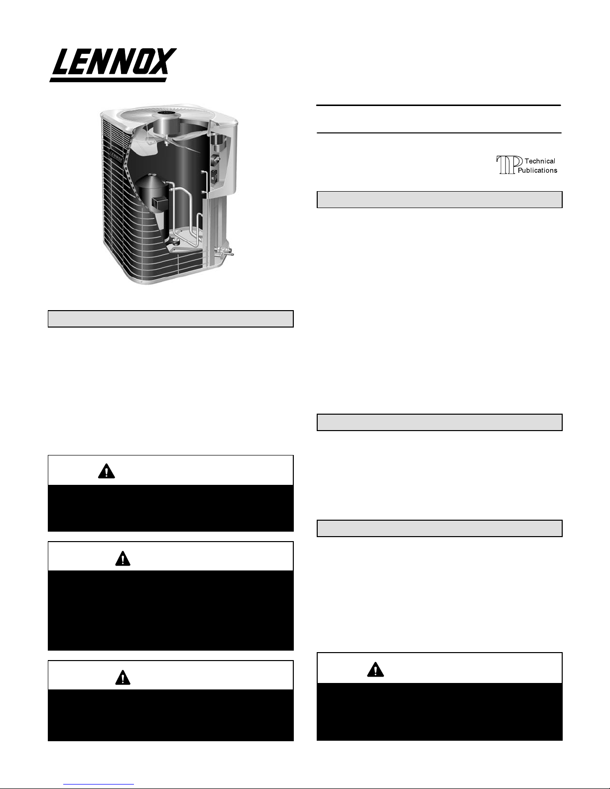
HP40 Heat Pump Unit
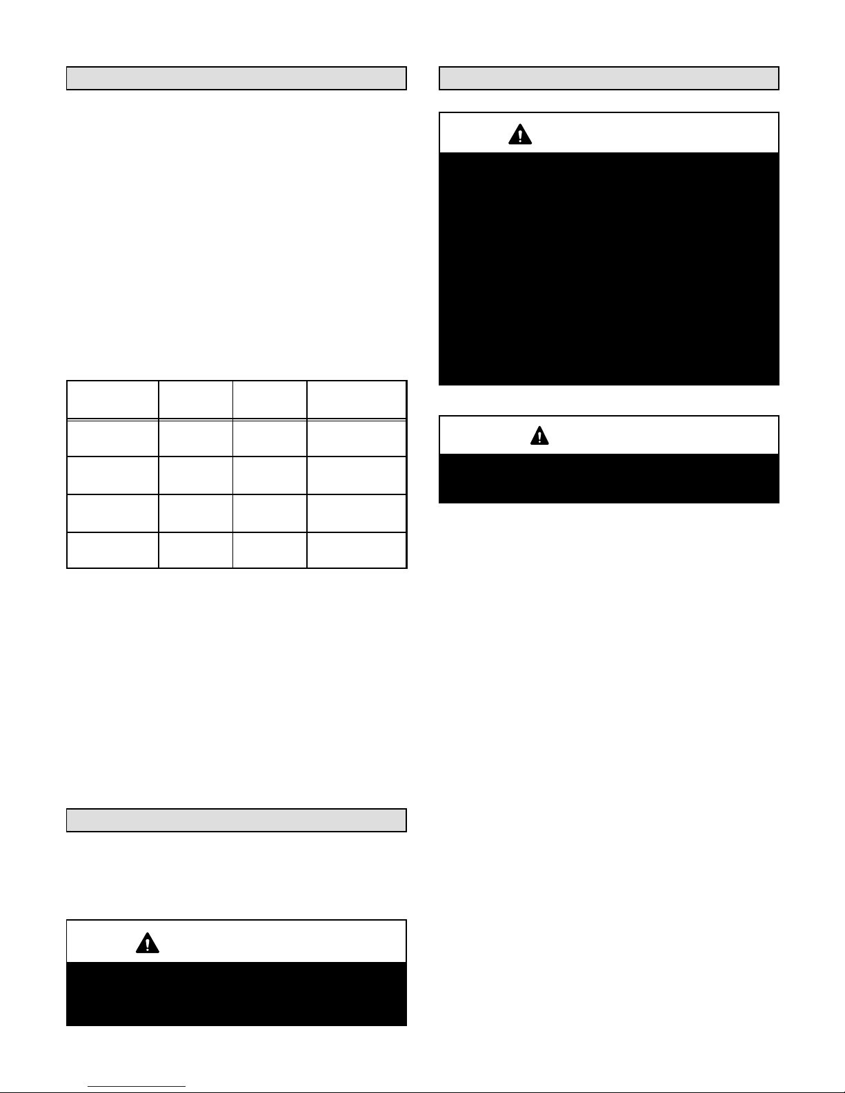
HP40 heat pumps use R407C which is an ozone friendly
HFC refrigerant. This unit must be installed with a matching indoor coil and line set as outlined in the Lennox Engineering Handbook. HP40 heat pumps are designed for
use in expansion valve systems only. They are not designed to be used in RFC systems. An expansion valve
and filter drier approved for use with R407C have been
shipped with the unit. These components must be
installed prior to unit operation.
IMPORTANT
This unit must be matched with an indoor coil as
specified in Lennox’ Engineering Handbook.
Coils previously charged with R22 must be
flushed.
WARNING
This equipment must only be installed and serviced
by properly qualified personnel. Equipment contains dangerous voltages and moving parts. Always switch off power supply before opening any
access panel. Electrical control panel doors and fan
access door must be locked to prevent unauthorized access at beginning of instruction.
WARNING
Refrigerant can be harmful if it is inhaled. Refrigerant must be used and recovered responsibly.
Failure to follow this warning may result in personal
injury or death.
INSTALLATION
INSTRUCTIONS
HP40 Heat Pump Units
HEAT PUMP UNITS
1−1/2 through 5 ton
504,538M
06/04
Supersedes 11/02
Table of Contents
HP40 Heat Pump Unit 1. . . . . . . . . . . . . . . . . . . . . . . . . .
Shipping & Packing List 1. . . . . . . . . . . . . . . . . . . . . . . . .
General Information 1. . . . . . . . . . . . . . . . . . . . . . . . . . . .
Unit Dimensions 2. . . . . . . . . . . . . . . . . . . . . . . . . . . . . . .
Setting the Unit 3. . . . . . . . . . . . . . . . . . . . . . . . . . . . . . . .
Electrical 4. . . . . . . . . . . . . . . . . . . . . . . . . . . . . . . . . . . . . .
Plumbing 5. . . . . . . . . . . . . . . . . . . . . . . . . . . . . . . . . . . . . .
Refrigerant Metering Device 5. . . . . . . . . . . . . . . . . . . . .
Manifold Gauge Set 7. . . . . . . . . . . . . . . . . . . . . . . . . . . .
Liquid & Vapor Line Service Valves 7. . . . . . . . . . . . . . .
Leak Testing 8. . . . . . . . . . . . . . . . . . . . . . . . . . . . . . . . . . .
System Evacuation 9. . . . . . . . . . . . . . . . . . . . . . . . . . . . .
Start−Up 9. . . . . . . . . . . . . . . . . . . . . . . . . . . . . . . . . . . . . . .
Charging Considerations 10. . . . . . . . . . . . . . . . . . . . . . .
System Operation 12. . . . . . . . . . . . . . . . . . . . . . . . . . . . .
Defrost System 12. . . . . . . . . . . . . . . . . . . . . . . . . . . . . . .
Maintenance 13. . . . . . . . . . . . . . . . . . . . . . . . . . . . . . . . . .
RETAIN THESE INSTRUCTIONS
FOR FUTURE REFERENCE
Shipping & Packing List
1 − Assembled HP40 heat pump unit
1 − Bag assembly:
1 − Sight glass
1 − Coupling reducer, 5/16 x 3/8 inch (024)
Check unit for shipping damage. If any damage is found,
contact the last carrier immediately.
General Information
These instructions are intended as a general guide and
do not supersede national or local codes in any way. Consult authorities having jurisdiction before installation.
The HP40 unit is CE marked" in accordance with the requirements of the latest European Directives for Electrical
and Machinery Safety and Electromagnetic Compatibility.
In addition, HP40 units have type Approval Certification
with the Gas Appliance Directive.
IMPORTANT
International Legislation bans the intentional venting of refrigerant (CFCs and HCFCs). Approved
methods of recovery, recycling or reclaiming must
be followed. Fines and/or incarceration may be levied for noncompliance.
Litho U.S.A.
Page 2
Page 2
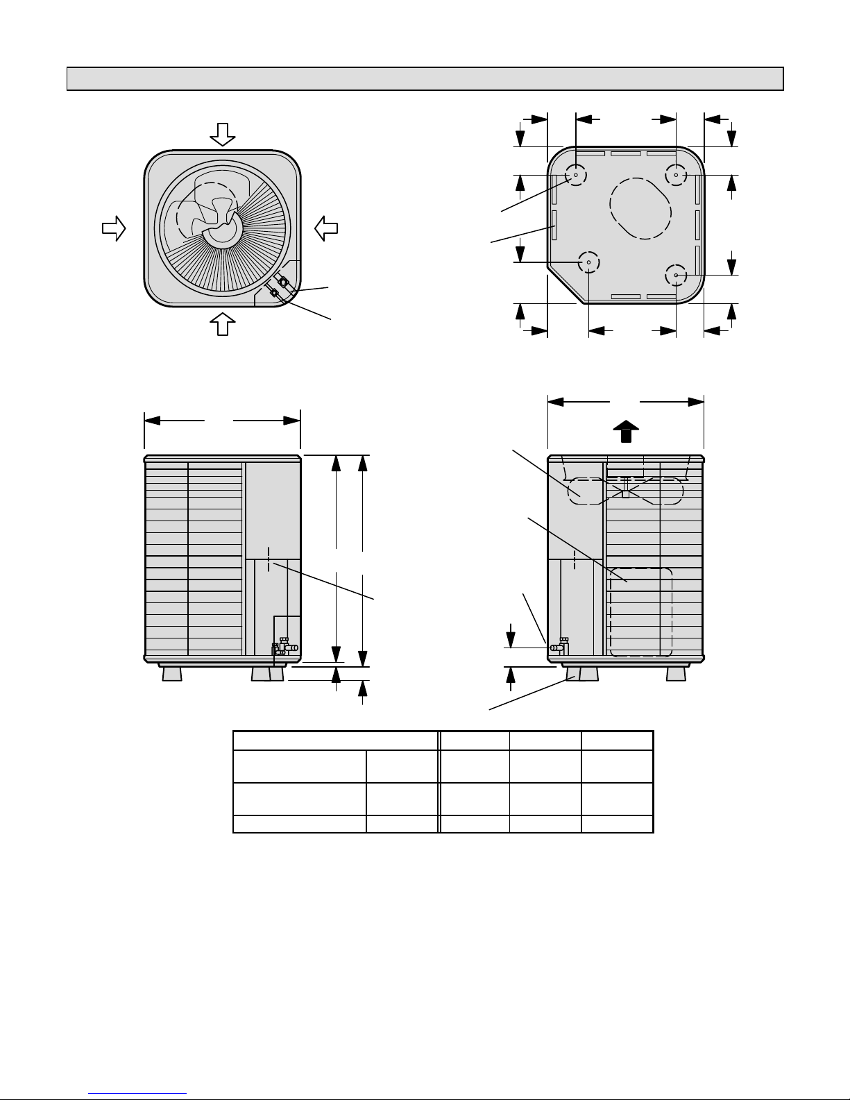
Unit Dimensions − mm
SIDE VIEW
VAPOR &
LIQUID LINE
CONNECTION
INLET
AIR
INLET
AIR
DISCHARGE AIR
SIDE VIEW
TOP VIEW
A
OUTDOOR
COIL FAN
COMPRESSOR
INLET AIR
INLET AIR
B
70
HP40
ELECTRICAL
INLETS
111
162
162
TOP VIEW BASE SECTION
51
19
111
111
111111
111
COMPRESSOR
COIL DRAIN OUTLETS
(Around perimeter of base)
OPTIONAL
STAND-OFF KIT
(Field−installed
4 required)
LIQUID LINE
CONNECTION
VAPOR LINE
CONNECTION
C
C
OPTIONAL
STAND-OFF KIT
(Field−installed
4 required)
Model Number A B C
HP40-018
HP40-024
mm 635 616 616
HP40-036
HP40-048
mm 838 819 616
HP40-060 mm 946 927 718
Page 3
Page 3
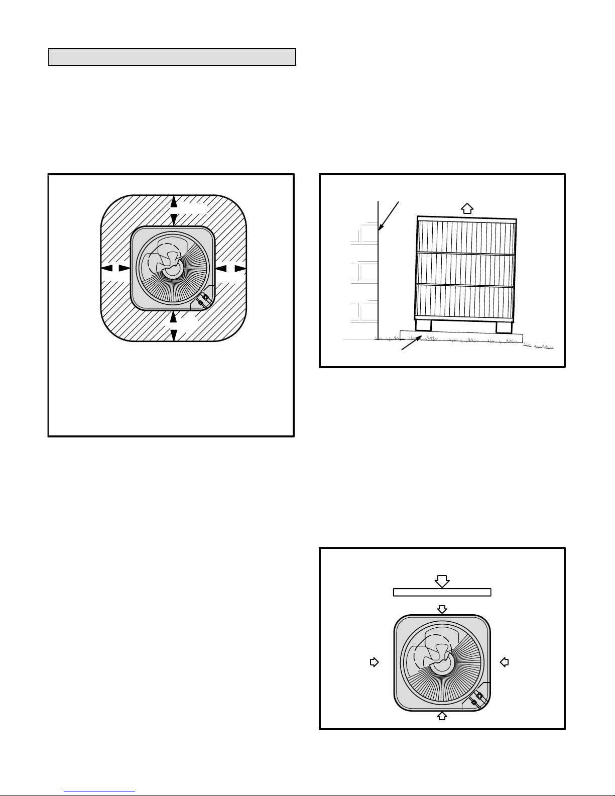
Setting the Unit
Heat pump units operate under a wide range of weather
conditions; therefore, several factors must be considered when positioning the outdoor unit. The unit must be
positioned to give adequate clearances for sufficient airflow and servicing. Maintain a minimum clearance of 610
mm between multiple units. Refer to figure 1 for installation clearances.
36
(914 mm)
Installation Clearances
36*
(914 mm)
*NOTE − A service clearance of 30" (762 mm) must be maintained on one of the sides adjacent to the control box. Clearance to one of the other three sides must be 36" (914 mm).
Clearance to one of the remaining two sides may be 12" (304
mm) and the final side may be 6" (152 mm).
36*
(914 mm)
NOTE − A clearance of 24" (610 mm) must be maintained
between two units.
NOTE − 48" (1219 mm) clearance required on top
of unit. Maximum soffit overhang is 36" (914 mm).
36
(914 mm)
FIGURE 1
1 − Place a sound-absorbing material, such as Isomode,
under the unit if it will be installed in a location or position that will transmit sound or vibration to the living
area or adjacent buildings.
2 − Install the unit high enough above the ground or roof
to allow adequate drainage of defrost water and prevent ice buildup.
3 − In areas that receive heavy snow, do not locate the
unit where drifting will occur. Ensure that the unit base
is elevated above the depth of average snows.
NOTE − Elevate the unit by constructing a frame using
suitable materials. If a support frame is constructed, it
must not block drain holes in the base of the unit.
4 − When you install the unit in areas where low ambient
temperatures exist, locate the unit so winter prevailing winds do not blow directly into outdoor coil.
5 − Locate unit away from overhanging roof lines which
would allow water or ice to drop on, or in front of, coil
or into unit.
Slab Mounting (See figure 2)
When the unit is installed at grade level, the top of the slab
should be high enough above the grade so that water
from higher ground will not collect around unit. Slab
should have a slope tolerance away from the building of 2
degrees or 51 mm per 1.5 m. This will prevent ice from
building up under the unit during a defrost cycle. Refer to
roof mounting section for barrier construction if unit must
face prevailing winter winds.
SLAB MOUNTING AT GROUND LEVEL
DISCHARGE AIR
MOUNTING SLAB MUST SLOPE
AWAY FROM BUILDING.
GROUND LEVEL
STRUCTURE
FIGURE 2
Roof Mounting (See figure 3)
If you are unable to mount the unit coil away from prevailing winter winds, construct a wind barrier. Size the barrier
at least the same height and width as the outdoor unit.
Mount the barrier 610 mm from the sides of the unit in the
direction of prevailing winds.
Install the unit at a minimum of 152 mm above the roof
surface to keep ice from building up around the unit. Locate the unit above a load bearing wall or area of the roof
that can adequately support the unit. Consult local codes
for rooftop applications.
WIND BARRIER
INLET AIR
INLET AIR
INLET AIR
INLET AIR
PREVAILING WINTER WINDS
ROOFTOP APPLICATION
WIND BARRIER CONSTRUCTION
FIGURE 3
Page 4
Page 4
Electrical
Wiring must conform with current local codes. An application diagram is included in this instruction and in the indoor
unit instructions.
Refer to the unit rating plate, located on the control box cover, for minimum circuit ampacity and maximum fuse size.
1 − Provide line voltage power supply to the unit from a
properly sized disconnect switch. The disconnect
switch should be located so that it is easily accessible
and within sight of the unit.
2 − Route the power and ground wires from the discon-
nect switch to the unit. The electrical openings are
provided under the control box cover. See the unit di-
mensions illustration on page 2.
3 − Remove the control box cover and connect the power
wiring to the contactor. Connect ground wire to ground
lug.
4 − Install the room thermostat (ordered separately) in
the conditioned area. Place the thermostat where it
will not be affected by sunlight, drafts, or vibration. Do
not install the thermostat on an outside wall. The most
desirable position for the thermostat is near the center of the conditioned area and approximately 1.5 m
from the floor.
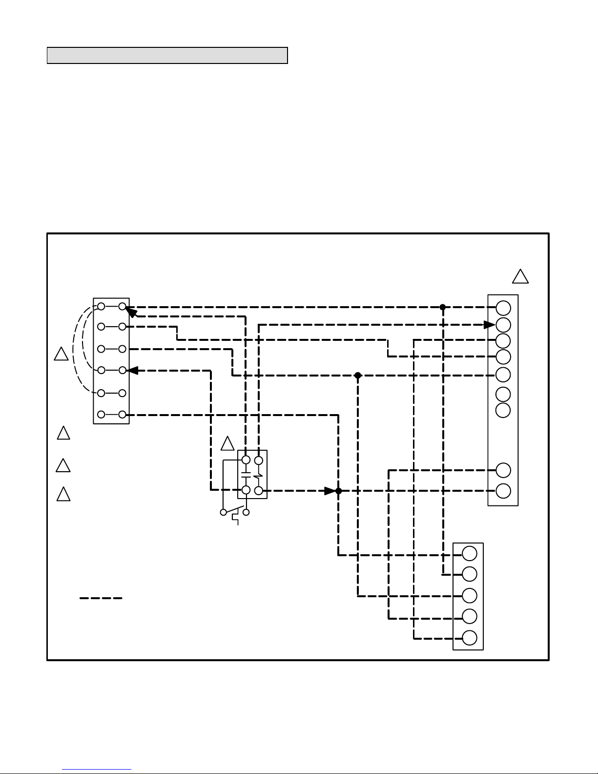
5 − Route 24VAC control wires from the thermostat to the
indoor unit and from the indoor unit to the defrost control terminals in the outdoor unit as shown in figure 4.
FIELD WIRING DIAGRAM FOR HP40 UNIT
W2
C
W1
G
O
Y1
S1 THERMOSTAT
1
LOW VOLTAGE
FIELD INSTALLED
1
EMERGENCY HEAT RELAY (USED ONLY
IF OUTDOOR THERMOSTAT IS USED)
FIELD PROVIDED AND INSTALLED NEAR
INDOOR UNIT 24VAC 5VA MAX NEC
CLASS 2.
2
NOTE−ALL REMAINING WIRES FACTORY INSTALLED
3
HP40
LOW VOLTAGE
TERMINAL
CONNECTIONS
THERMOSTAT HEAT ANTICIPATION SETTING .4 AMP ELECTRIC HEAT FOR THERMOSTATS WITH ADJUSTABLE ANTICIPATORS.
IF OUTDOOR THERMOSTAT IS USED, REMOVE JUMPER BETWEEN TERMINALS R"
AND W2."
R
Y2
E
COMMON
BEIGE (ELECTRIC HEAT)
ORANGE
YELLOW (COMPRESSOR)
RED (POWER)
TB1 TERMINAL STRIP
(INDOOR UNIT CONTROL BOX)
C
G
W1
W2
W3
R
S23
EM HEAT RELAY K26
OUTDOOR
THERMOSTAT
(IF USED)
2
3
R
C
O
W1
Y1
REVERSINNG VALVE
FIGURE 4
Page 5
Page 5
Plumbing
Field refrigerant piping consists of liquid and vapor lines
from the heat pump (sweat connections) to the indoor
evaporator coil. Use Lennox L15 (sweat connection) series line sets as shown in table 1 or use field-fabricated refrigerant lines. Refer to Refrigerant Piping Guide (Corp.
9351−L9) for proper size, type, and application of field−
fabricated lines.
If refrigerant tubes are routed through a wall, seal and isolate the opening so vibration is not transmitted to the
building.
NOTE − Line length should be no greater than 15.2 m. Select line set diameters from table 1 to ensure that the oil
returns to the compressor.
TABLE 1
REFRIGERANT LINE SET KITS
HP40 UNIT
LIQUID
LINE
SUCTION
LINE
L15 LINE
SETS
HP40−024 8 mm* 16 mm
L15 − 21
4.6 m − 15 m
HP40−036 10 mm 19 mm
L15 − 41
4.6 m − 15 m
HP40−048 10 mm 22 mm
L15 − 65
4.6 m − 15 m
HP40−060 10 mm 29 mm
FIELD
FABRICATED
*Use the coupling reducer that is supplied in the bag assembly.
Sweat Connection Procedure
1 − The ends of refrigerant lines must be cut square, free
from nicks or dents and deburred. The pipe must remain round. Do not pinch the end of the line.
2 − Wrap a wet cloth around the liquid line valve body and
copper tube stub to protect them from heat damage
during brazing. Wrap another wet cloth underneath
the liquid valve to protect the base paint.
3 − Quench the joints with a wet cloth to prevent possible
heat damage to the valve core and opening port.
Refrigerant Metering Device
HP40 units are applicable to thermal expansion valve
systems only. An expansion valve appropriate for use
with R407C refrigerant is shipped with the outdoor unit.
IMPORTANT
Failure to remove an existing refrigerant flow control orifice when installing an expansion valve on
the indoor coil will result in improper operation and
damage to the system.
Flushing Existing Line Set and Indoor Coil
IMPORTANT
If this unit is being matched with an approved line
set or indoor coil which was previously charged
with R22 refrigerant, or if it is being matched with
a coil which was manufactured before January of
1999, the coil and line set must be flushed prior to
installation. Take care to empty all existing traps.
Polyol ester (POE) oils are used in Lennox units
charged with R407C refrigerant. Polyol ester oils
are not compatible with mineral oils. Residual
mineral oil can act as an insulator, preventing
proper heat transfer. It can also clog the thermal
expansion valve, reducing system performance
and capacity.
Failure to properly flush the system per the instructions below will void the warranty.
CAUTION
This procedure should not be performed on systems which contain contaminants (Example:
compressor burn out).
Required Equipment
You will need the following equipment in order to flush the
existing line set and indoor coil: two clean R22 recovery
bottles, an oilless recovery machine with a pump down
feature, and two sets of gauges (one or use with R22 and
one for use with the R407C).
Flushing Procedure
1 − Remove existing R22 refrigerant using the appropri-
ate procedure below.
If the existing outdoor unit is not equipped with shut−
off valves, or if the unit is not operational AND you
plan to use the existing R22 refrigerant to flush the
system −− Disconnect all power to the existing out-
door unit. Connect the existing unit, a clean recovery
cylinder and the recovery machine according to the
instructions provided with the recovery machine. Remove all R22 refrigerant from the existing system.
Refer to gauges after shutdown to confirm that the
entire system is completely void of refrigerant. Disconnect the liquid and vapor lines from the existing
outdoor unit.
If the existing outdoor unit is equipped with manual
shut−off valves AND you plan to use NEW R22 refrigerant to flush the system −− Start the existing R22 sys-
tem in the cooling mode and close the liquid line
valve. Pump all of the existing R22 refrigerant back
into the outdoor unit. (It may be necessary to bypass
Page 6

Page 6
the low pressure switches to ensure complete refrigerant evacuation.) When low side system pressures
reach 0 psig, close the suction line valve. Disconnect
all power to the existing outdoor unit. Refer to gauges
after shutdown to confirm that the valves are not allowing refrigerant to flow back into the low side of the
system. Disconnect the liquid and vapor lines from
the existing outdoor unit.
2 − Remove the existing outdoor unit. Set the new
R407C unit and follow the brazing connection procedure to make line set connections. DO NOT install
provided R407C check/expansion valve at this
time.
Make low voltage and line voltage connections to the
new outdoor unit. DO NOT turn on power to the
unit or open the outdoor unit service valves at
this time.
3 − Remove the existing refrigerant flow control orifice or
thermal expansion/check valve before continuing
with flushing procedures. The existing devices are
not approved for use with R407C refrigerant and may
prevent proper flushing. Use a field−provided fitting to
reconnect the lines.
4 − Remove the pressure tap valve cores from the HP32
unit’s service valves. Connect an R22 cylinder with
clean refrigerant to the suction service valve. Connect the R22 gauge set to the liquid line valve and
connect a recovery machine with an empty recovery
tank to the gauge set.
IMPORTANT
The line set and indoor coil must be flushed with
at least the same amount of clean refrigerant that
previously charged the system. Check the charge
in the flushing cylinder before proceeding.
5 − Set the recovery machine for liquid recovery and
start the recovery machine. Open the gauge set
valves to allow the recovery machine to pull a vacuum on the existing system line set and indoor coil.
6 − Invert the cylinder of clean R22 and open its valve to
allow liquid refrigerant to flow into the system through
the suction line valve. Allow the refrigerant to pass
from the cylinder, through the line set and the indoor
coil before entering the recovery machine.
7 − After all of the liquid refrigerant has been recovered,
switch the recovery machine to vapor recovery so
that all of the R22 vapor is recovered. All the recovery
machine to pull a vacuum on the system.
NOTE − A single system flush should remove all of
the mineral oil from the existing refrigerant lines and
indoor coil. A second flushing may be done (using
clean refrigerant) if insufficient amounts of mineral oil
were removed during the first flush. Each time the
system is flushed, you must allow the recovery
machine to pull a vacuum on the system at the
end of the procedure.
FLUSHING CONNECTIONS
LOW
PRESSURE
HIGH
PRESSURE
SUCTION LINE
SERVICE VALVE
INDOOR COIL
HP40 UNIT
GAUGE MANIFOLD
RECOVERY MACHINE
INVERTED R22
CYLINDER
LIQUID LINE
SERVICE VALVE
INLET
DISCHARGE
TANK RETURN
CLOSEDOPENED
EXISTING
EXISTING SUCTION LINE
EXISTING LIQUID LINE
RECOVERY
CYLINDER
FIGURE 5
Page 7

Page 7
HP40 COOLING CYCLE (SHOWING MANIFOLD GAUGE CONNECTIONS)
OUTDOOR
COIL
DEFROST THERMOSTAT
EXPANSION/CHECK
VALV E
BIFLOW
FILTER / DRIER
TO
R407C
DRUM
LOW
PRESSURE
HIGH
PRESSURE
COMPRESSOR
REVERSING VALVE
VAPOR
LINE
VALV E
MUFFLER
NOTE − ARROWS INDICATE DIRECTION OF REFRIGERANT FLOW
SERVICE
PORT
SUCTION
EXPANSION/CHECK
VALV E
INDOOR UNIT
OUTDOOR UNIT
LIQUID LINE
SERVICE
PORT
GAUGE MANIFOLD
INTERNAL
COMPRESSOR
LIMIT
DISTRIBUTOR
INDOOR
COIL
FIGURE 6
8 − Close the valve on the inverted R22 drum and the
gauge set valves. Pump the remaining refrigerant
out of the recovery machine and turn the machine off.
9 − Use nitrogen to break the vacuum on the refrigerant
lines and indoor coil before removing the recovery
machine, gauges and R22 refrigerant drum. Reinstall pressure tap valve cores into HP32 service
valves.
10 −Install the provided check/expansion valve (ap-
proved for use with R407C refrigerant) in the liquid
line at the indoor coil.
Manifold Gauge Set
Manifold gauge sets used with systems charged with
R407C refrigerant must be able to accommodate higher
system operating pressures. The gauges should be rated
for pressures of 0−800 psi on the high side and a low side
of 30" vacuum to 250 psi with dampened speed of 500 psi.
Gauge hoses must be rated for use at up to 800 psi of
pressure with a 4000 psi burst rating.
Liquid & Vapor Line Service Valves
Access the liquid line and vapor line service valves (figures 7 and 8) and the gauge ports from inside the unit, behind access panel. The service ports are used for leak
testing, evacuating, charging, and checking the charge.
The valve is equipped with a service port, and a Schrader
valve is factory installed. A service port cap is supplied to
protect the Schrader valve from contamination and to serve
as the primary leak seal.
LIQUID AND VAPOR LINE SERVICE VALVES
VALVE OPEN)
SCHRADER
VALV E
SERVICE
PORT
SERVICE
PORT
CAP
INSERT HEX
WRENCH HERE
TO INDOOR
COIL
TO OUTDOOR
COIL
STEM CAP
SCHRADER VALVE OPEN
TO LINE SET WHEN VALVE IS
CLOSED (FRONT SEATED)
SERVICE
PORT
SERVICE
PORT CAP
STEM CAP
TO OUTDOOR
COIL
INSERT HEX
WRENCH HERE
(VALVE CLOSED)
(VALVE FRONT
SEATED)
TO INDOOR COIL
FIGURE 7
Page 8

Page 8
IMPORTANT
Service valves are closed to the heat pump unit and
open to line set connections. Do not open until refrigerant lines have been leak tested and evacuated. All precautions should be exercised in keeping
the system free from dirt, moisture and air.
Accessing the Schrader Port:
1 − Remove service port cap with an adjustable wrench.
2 − Connect gauge to the service port.
3 − When testing is completed, replace the service port
cap. Tighten finger tight, then tighten an additional 1/6
turn.
To Open Liquid or Vapor Line Service Valve:
1 − Remove the stem cap with an adjustable wrench.
2 − Use a service wrench with a hex−head extension to
back the stem out counterclockwise as far as possible.
WARNING
Do not attempt to backseat this valve. Attempts to
backseat this valve will cause the snap ring to explode from the valve body under pressure of the refrigerant. Personal injury and unit damage will result.
3 − Replace the stem cap. Tighten finger tight, then tighten
an additional 1/6 turn.
To Close Liquid or Vapor Line Service Valve:
1 − Remove the stem cap with an adjustable wrench.
2 − Use a service wrench with a hex−head extension to
turn the stem clockwise to seat the valve. Tighten
firmly.
3 − Replace the stem cap. Tighten finger tight, then tight-
en an additional 1/6 turn.
VAPOR LINE (BALL−TYPE) SERVICE VALVE
(VALVE OPEN)
SCHRADER
VALV E
SERVICE PORT
SERVICE
PORT
CAP
STEM CAP
TO OUTDOOR
COIL
STEM
USE ADJUSTABLE WRENCH.
ROTATE STEM CLOCKWISE 90 TO CLOSE.
ROTATE STEM COUNTERCLOCKWISE 90 TO OPEN.
BALL
(SHOWN OPEN)
TO INDOOR COIL
FIGURE 8
Vapor Line (Ball−Type) Service Valve −− 5−Ton Units
A ball-type full−service valve is used on five-ton units. These
vapor line service valves function the same way, the differences are in construction. Valves are not rebuildable. If a
valve has failed, it must be replaced. A ball valve is illustrated in figure 8.
The ball valve is equipped with a service port and a factory−installed Schrader valve. A service port cap is
supplied to protect the Schrader valve from contamination and to assure a leak−free seal.
Leak Testing
After the line set has been connected to the indoor and
outdoor units, check all connections for leaks.
IMPORTANT
The leak detector must be capable of sensing HFC
refrigerant.
WARNING
Never use oxygen to pressurize refrigeration or air
conditioning system. Oxygen will explode on contact with oil and could cause personal injury. When
using high pressure gas such as nitrogen for this
purpose, be sure to use a regulator that can control
the pressure down to a range of 6.9 to 13.8 kPa.
Using an Electronic Leak Detector
1 − Connect a cylinder of nitrogen with a pressure regulat-
ing valve to center port of manifold gauge set.
2 − Connect the high pressure hose of the manifold
gauge set to the service port of the vapor valve. (Normally, the high pressure hose is connected to the liquid line port, however, connecting it to the vapor port
better protects the manifold gauge set from high pressure damage.)
3 − With both manifold valves closed, open the valve on
the R407C cylinder (liquid only).
4 − Open the high pressure side of the manifold to allow
R407C into the line set and indoor unit. Weigh in a
trace amount of R407C. (A trace amount is a maximum of 59 ml or 21 kPa pressure.) Close the valve on
the R407C cylinder and the valve on the high pressure side of the manifold gauge set. Disconnect
R407C cylinder and attach a nitrogen cylinder.
5 − Adjust nitrogen pressure to 1034 kPa. Open the valve
on the high side of the manifold gauge set which will
pressurize line set and indoor unit.
6 − After a short period of time, open a refrigerant port to
make sure the refrigerant added is adequate to be detected. (Amounts of refrigerant will vary with line
lengths.) Check all joints for leaks. Purge nitrogen
and R407C mixture. Correct any leaks and recheck.
Page 9

Page 9
System Evacuation
WARNING
Unit contains a NITROGEN holding charge. The
holding charge must be purged and the system
must be evacuated prior to charging with R407C.
Evacuating the system of non−condensables is critical for
the unit to operate properly. Non−condensables are defined as any gas that will not condense under temperatures
and pressures present during operation of an air conditioning system. Non−condensables and water vapor combine
with refrigerant to produce substances that corrode copper
piping and compressor parts.
1− Connect manifold gauge set to the service valve ports
as follows:
low pressure gauge to suction line service valve
high pressure gauge to liquid line service valve
IMPORTANT − Compliant scroll compressors (as with
any refrigerant compressor) should never be used to
evacuate a refrigeration or air conditioning system.
NOTE − Use a temperature vacuum gauge, mercury
vacuum, or thermocouple gauge. The usual Bourdon
tube gauges are inaccurate in the vacuum range.
2 −The nitrogen holding charge in the unit must be re-
leased. Open both manifold valves to release the nitrogen from the unit. See the liquid and suction line
service valves section for how to operate the service
valves.
3 −Connect the vacuum pump (with vacuum gauge) to
the center port of the manifold gauge set.
4 −Open both manifold valves and start the vacuum
pump.
5 −Evacuate the line set, condensing unit, and indoor
unit to an absolute pressure of 23 mm (23,000 mi-
crons) of mercury. During the early stages of evacuation, it is desirable to close the manifold gauge valve
at least once to determine if there is a rapid rise in ab-
solute pressure. A rapid rise in pressure indicates a
relatively large leak. If this occurs, the leak testing
procedure must be repeated.
NOTE − The term absolute pressure means the total
actual pressure within a given volume or system,
above the absolute zero of pressure. Absolute pressure in a vacuum is equal to atmospheric pressure
minus vacuum pressure.
6 − When the absolute pressure reaches 23 mm (23,000
microns) of mercury, close the manifold gauge
valves, turn off the vacuum pump, and disconnect the
manifold gauge center port hose from the vacuum
pump. Attach the manifold center port hose to a nitro-
gen cylinder with the pressure regulator set to 150
psig (1034 kPa) and purge the hose. Open the manifold gauge valves to break the vacuum in the system.
Close the manifold gauge valves.
WARNING
Danger of Equipment Damage.
Avoid deep vacuum operation. Do not use compressors to evacuate a system.
Extremely low vacuums can cause internal arcing
and compressor failure.
Damage caused by deep vacuum operation will
void warranty.
7 −Shut off the nitrogen cylinder and remove the man-
ifold gauge hose from the cylinder. Open the manifold
gauge valves to release the nitrogen from the system.
8 −Reconnect the manifold gauge to the vacuum pump,
turn the pump on and continue to evacuate the system
until the absolute pressure does not rise above .5 mm
(500 microns) of mercury within a 20−minute period after shutting off the vacuum pump and closing the manifold gauge valves.
9 − When the absolute pressure requirement from step 9
has been met, disconnect the manifold gauge hose
from the vacuum pump. Then, weigh in a LIQUID
charge of R407C through the liquid and suction service valves.
Refer to the unit nameplate for the correct liquid
charge. If you can not measure in the total amount, refer to the start−up section and set the final system
charge according to the charging instructions. The
R407C refrigerant cylinder should be chocolate
brown.
Start−Up
Cooling Start-Up
1 − Check the unit disconnect switch to make sure power
is off.
2 − Rotate the fan to check for frozen bearings or binding.
3 − Inspect all factory and field-installed wiring for loose
connections.
4 − Replace the stem caps. Tighten finger tight, then
tighten an additional 1/6 turn.
5 − Check the voltage supply at the disconnect switch.
The voltage must be within the range listed on the unit
nameplate. If not, do not start the equipment until the
you have consulted the power company, and the voltage condition has been corrected.
6 − Set the thermostat for cooling demand, turn on the
power to the indoor blower coil, and close the heat
pump unit disconnect switch to start the unit.
Page 10

Page 10
7 − Recheck the unit voltage while the unit is running.
The power must be within the range shown on the
unit nameplate. Check the amperage draw of the
unit. Refer to the unit nameplate for approximate
running amps.
Charging
Liquid charge the unit with the amount of R407C refrigerant that is indicated on the nameplate.
IMPORTANT
If existing refrigerant lines which were previously
charged with R22 are going to be used, they must
first be flushed of existing mineral oil. Take care
to empty all existing traps. Polyol ester (POE) oils
are used in Lennox units charged with R407C refrigerant. Mineral oils are not compatible with
polyol ester oils.
This charge is based on a matching indoor coil and outdoor coil with a 4.6 m line set. For varying lengths of line
set, refer to table 2 for refrigerant charge adjustment.
TABLE 2
Liquid Line
Set Diameter
g per 1524 mm adjust
from 4.6 m line set*
8 mm 57 g per 1524 mm
10 mm 85 g per 1524 mm
*If line length is greater than 4.6 m, add this amount.
If line length is less than 4.6 m, subtract this amount.
Charging Using the Subcooling Method
If the outdoor ambient temperature is below 13C, airflow
over the outdoor coil will need to be reduced to drive up
the liquid line pressure to a range of 1379 to 1724 kPa. To
do this, block off the outdoor coil with cardboard or a plastic sheet.
BLOCKING OUTDOOR COIL
CARDBOARD OR
PLASTIC SHEET
OUTDOOR COIL SHOULD
BE BLOCKED ONE SIDE
AT A TIME WITH CARD−
BOARD OR PLASTIC
SHEET UNTIL PROPER
TESTING PRESSURES
ARE REACHED.
FIGURE 9
1 − Remove the cap from the liquid line service valve
stem and turn the stem clockwise 1/4 to 1/2 turn. This
will open the service port.
2 − With the manifold gauge hose still on the liquid ser-
vice port and the unit operating, read the liquid line
pressure.
3 − If the pressure is too low, block the airflow through
the outdoor coil until the liquid line pressure stabilizes in a range from 1379 to 1724 kPa. At that time,
record the liquid line temperature and the liquid line
pressure reading.
4 − Use a temperature/pressure chart for R407C to de-
termine the saturation temperature for the liquid line
pressure reading.
5 − Subtract the liquid line temperature from the satura-
tion temperature (according to the chart) to determine
subcooling. (Saturation temperature − Liquid line
temperature = Subcooling.) Subcooling should
be between 4.4−5.5°C. If subcooling is greater than
4.4 − 5.5°C, recover some refrigerant. If subcooling is
less than 4.4 − 5.5°C, add some refrigerant.
Page 11

Page 11
TABLE 3
R407C Saturated Liquid Temperature and Pressure Chart
Use this chart for subcooling only, not superheat.
Liquid Line Pressure
Liquid Line Pressure
S
aturated Liqu
id
Temperature °C
R407C
Psig (kPa)
R22
Psig (kPa)
S
aturated Liqu
id
Temperature °C
R407C
Psig (kPa)
R22
Psig (kPa)
15 116 (799) 102 (703) 33 197 (1358) 174 (1199)
16 118 (813) 104 (717) 33 200 (1378) 176 (1213)
16 120 (827) 105 (723) 34 203 (1399) 179 (1234)
17 123 (848) 107 (737) 35 206 (1420) 182 (1254)
17 125 (861) 109 (751) 35 210 (1447) 184 (1268)
18 127 (875) 111 (765) 36 213 (1468) 187 (1289)
18 129 (889) 113 (779) 36 216 (1489) 190 (1310)
19 131 (903) 115 (792) 37 219 (1509) 193 (1330)
20 134 (923) 117 (806) 37 222 (1530) 196 (1351)
20 136 (937) 119 (820) 38 226 (1558) 199 (1372)
21 138 (951) 121 (834) 38 229 (1578) 202 (1392)
21 141 (972) 123 (848) 39 232 (1599) 205 (1413)
22 143 (985) 126 (868) 40 236 (1627) 208 (1431)
22 146 (1006) 128 (882) 40 239 (1647) 211 (1454)
23 148 (1020) 130 (896) 41 242 (1668) 214 (1475)
23 151 (1041) 132 (910) 41 246 (1696) 217 (1496)
24 153 (1054) 134 (923) 42 249 (1716) 220 (1516)
25 156 (1075) 137 (944) 42 253 (1744) 223 (1537)
25 158 (1089) 139 (958) 43 257 (1771) 226 (1558)
26 161 (1110) 141 (972) 43 260 (1792) 229 (1578)
26 163 (1123) 144 (992) 44 264 (1820) 233 (1606)
27 166 (1144) 146 (1006) 45 268 (1847) 236 (1627)
27 169 (1165) 148 (1020) 45 271 (1868) 239 (1647)
28 171 (1179) 151 (1041) 46 275 (1896) 243 (1675)
28 174 (1199) 153 (1054) 47 279 (1923) 246 (1696)
29 177 (1220) 156 (1075) 47 283 (1951) 250 (1723)
30 180 (1241) 158 (1089) 47 287 (1978) 253 (1744)
30 183 (1261) 161 (1110) 48 290 (1999) 256 (1765)
31 186 (1282) 163 (1123) 48 294 (2027) 260 (1792)
31 188 (1296) 166 (1144) 51 315 (2171) 278 (1916)
32 191 (1316) 168 (1158) 54 336 (2316) 297 (2047)
32 194 (1337) 171 (1179) 57 358 (2468) 317 (2185)
Page 12

Page 12
System Operation
Filter Drier
The unit is equipped with a biflow filter drier. See figure 6.
If the filter needs to be replaced, order another of the
same design.
Thermostat Operation
Some heat pump thermostats incorporate isolating contacts and an emergency heat function (which includes an
amber indicating light). The thermostat is not included
with the unit and must be purchased separately.
Emergency Heat Function
Some thermostats have an emergency heat function.
This feature is applicable only to those systems that have
auxiliary electric heat staged by outdoor thermostats.
When the thermostat is placed in the emergency heat
position, the outdoor unit control circuit is isolated from
the power source, and field−provided relays bypass the
outdoor thermostats. An amber indicating light simultaneously comes on to remind the homeowner that the unit
is operating in the emergency heat mode.
Emergency heat is usually used during a heat pump shutdown. However, emergency heat should also be used following a power outage if the power has been off for over
an hour, and the outdoor temperature is below 10C. The
system should be left in the emergency heat mode for at
least six hours to allow the crankcase heater sufficient
time to prevent compressor from slugging.
Defrost System
The HP40 defrost system includes two components: a defrost thermostat and a defrost control.
Defrost Thermostat
The defrost thermostat is located on the liquid line between the check/expansion valve and the distributor.
When defrost thermostat senses 5.5°C or cooler, the thermostat contacts close and send a signal to the defrost
control board to start the defrost timing. It also terminates
defrost when the liquid line warms up to 21°C.
Defrost Control
The defrost control board includes the combined functions of a time/temperature defrost control, defrost relay,
diagnostic LEDs and terminal strip for field wiring connections. See figure 10.
The control provides automatic switching from normal
heating operation to defrost mode and back. During compressor cycle (call for defrost), the control accumulates
compressor run times at 30, 60, or 90 minute field−adjustable intervals. If the defrost thermostat is closed when the
selected compressor run time interval ends, the defrost
relay is energized and defrost begins.
HP40 DEFROST CONTROL BOARD
24V
TERMINAL
STRIP
HIGH PRESSURE SWITCH
SAFETY CIRCUIT
CONNECTIONS
NOTE − Remove factory−
installed jumper to add
pressure switch.
S4
CONNECTION FOR
OPTIONAL
HIGH PRESSURE
SWITCH
DEFROST
INTERVAL
TIMING PINS
High
Pressure
Switch
DIAGNOSTIC
LEDs
FIGURE 10
Page 13

Page 13
Defrost Control Timing Pins
Each timing pin selection provides a different accumulated compressor run time period during one thermostat run cycle. This time period must occur before a defrost cycle is initiated. The defrost interval can be adjusted to 30 (T1), 60 (T2), or 90 (T3) minutes. See figure
10. The defrost timing jumper is factory−installed to provide a 60−minute defrost interval. If the timing selector
jumper is not in place, the control defaults to a 90−minute defrost interval. The maximum defrost period is 14
minutes and cannot be adjusted.
A TEST option is provided for troubleshooting. The TEST
mode may be started any time the unit is in the heating mode and the defrost thermostat is closed or
jumpered. If the jumper is in the TEST position at power-
up, the control will ignore the test pins. When the jumper is
placed across the TEST pins for two seconds, the control
will enter the defrost mode. If the jumper is removed before an additional 5−second period has elapsed (7 seconds total), the unit will remain in defrost mode until the
defrost thermostat opens or 14 minutes have passed. If
the jumper is not removed until after the additional 5−second period has elapsed, the defrost will terminate and the
test option will not function again until the jumper is removed and re−applied.
Pressure Switch Circuit
The defrost control incorporates a pressure switch circuit
that allows the application of an optional high pressure
switch. See figure 10. During a demand cycle, the defrost
control will lock out the unit if the optional high pressure
switch opens. The diagnostic LEDs will display a pattern
for an open high pressure switch. See table 3. The unit will
remain locked out until the switch resets or is reset.
Remove the factory-installed jumper before connecting
the optional high pressure switch to the control board.
NOTE − If not using a pressure switch, the factoryinstalled jumper wire must be connected.
Diagnostic LEDs
The defrost board uses two LEDs for diagnostics. The
LEDs flash a specific sequence according to the condition.
TABLE 3
DEFROST CONTROL BOARD DIAGNOSTIC LED
MODE LED 1 LED 2
Normal operation /
power to board
Synchronized
Flash with LED 2
Synchronized
Flash with LED 1
Board failure or no power Off Off
Board failure On On
High pressure switch open Flash On
Maintenance
WARNING
Electric shock hazard. Can cause injury or death. Before attempting to
perform any service or maintenance,
turn the electrical power to unit OFF
at disconnect switch(es). Unit may
have multiple power supplies.
At the beginning of each heating or cooling season, check
the system as follows:
Heat Pump Unit
1 − Clean and inspect the outdoor coil. You may flush the
coil with a water hose. Make sure the power is off before you clean the coil.
2 − The outdoor unit fan motor is pre-lubricated and
sealed. The fan motor requires no more lubrication.
3 − Inspect all connecting lines, joints, and coils for evi-
dence of oil leaks.
4 − Check all wiring for loose connections.
5 − Check for correct voltage at the unit while the unit is
operating.
6 − Check amp draw on the heat pump fan motor.
Unit nameplate__________Actual__________.
7 − Inspect the drain holes in the coil compartment base
and clean them if necessary.
NOTE − If insufficient heating or cooling occurs, gauge the
unit and check the refrigerant charge.
Indoor Coil
1 − If necessary, clean the coil.
2 − Inspect the connecting lines, joints, and coil for evi-
dence of oil leaks.
4 − Check all wiring for loose connections.
5 − Check for correct voltage at the unit.
6 − Check the amp draw on the blower motor.
Motor nameplate__________Actual__________.
3 − Check the condensate line and clean it if necessary.
Indoor Unit
1 − Clean or change the filters.
2 − Lennox blower motors are pre-lubricated and perma-
nently sealed. The blower motor requires no more lubrication.
3 − Adjust the blower speed for cooling. Measure the
pressure drop over the coil to determine the correct
blower m
3
/s.
Page 14

Page 14
Start−Up and Performance Check List
Job Name
Job Location
Installer
Unit Model No.
Nameplate Voltage
Minimum Circuit Ampacity
Maximum Overcurrent Protection Size
Refrigerant Lines:
Outdoor Fan Checked?
Job No.
City
City
Serial No.
Date
State
State
Service Technician
Amps:
Supply Outdoor Fan
Compressor
Indoor Filter Clean?
Indoor Blower RPM
Electrical Connections Tight?
Supply Voltage (Unit Off)
Outdoor Coil Entering Air Temperature
Discharge Pressure Suction Pressure
COOLING SECTION
THERMOSTAT
Refrigerant Charge Checked?
Calibrated? Properly Set?
Level?
Properly Insulated?
Voltage With Compressor Operating
Leak Checked?
Service Valve Caps Tight?
S.P. Drop Over Evaporator (Dry)
Service Valves Fully Opened?
Page 15

Page 15
Page 16

Page 16
Lennox Industries
P.O. Box 174, Westgate Interchange,
Northampton NN5 5AG
Telephone: 01604 591159
Facsimile: 01604 587536
 Loading...