

Page 1
2001 Lennox Industries Inc.
Litho U.S.A.
Corp. 0101−L1
HP29
Service Literature
Litho U.S.A.
Heat Pumps−7.5 &10 Ton
(26.4 & 35.2 kw)
Revised 06−2003
HP29 HEAT PUMP SERIES
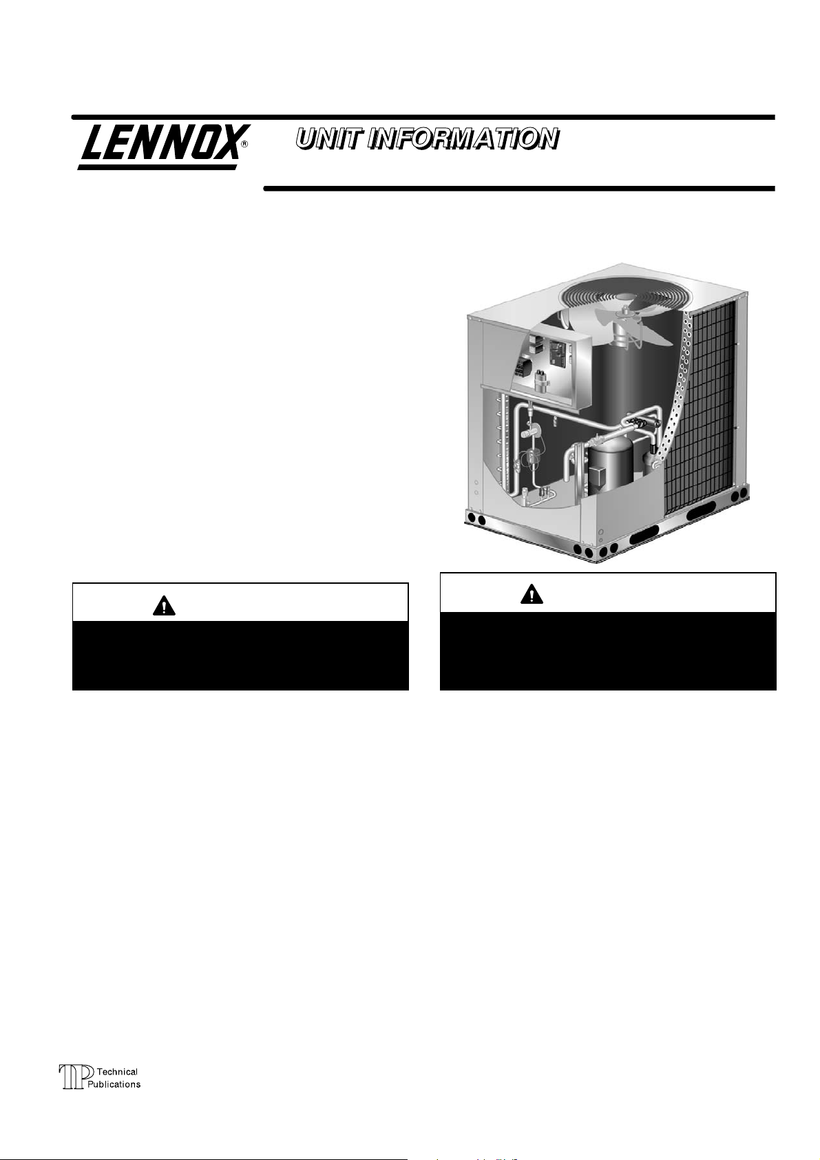
The HP29 7.5 and 10 (26.4 and 35.2 kW) ton heat pump
units are designated for light commercial applications, with
a remotely located blower−coil unit or a furnace with an
add−on evaporator coil. HP29 model units are equipped
with a scroll compressor. The HP29 heat pumps match
with the CB/CBH17 blower−coil units. All HP29 units are
three−phase.
This manual is divided into sections which discuss the ma
jor components, refrigerant system, charging procedure,
maintenance and operation sequence.
Information in this manual is intended for qualified service
technicians only. All specifications are subject to change.
Procedures in this manual are presented as recommenda
tions only and do not supersede or replace local or state
codes.
WARNING
Refrigerant can be harmful if it is inhaled. Refriger
ant must be used and recovered responsibly.
Failure to follow this warning may result in person
al injury or death.
HP29−090
WARNING
Improper installation, adjustment, alteration, ser
vice or maintenance can cause property damage,
personal injury or loss of life. Installation and service
must be performed by a qualified installer or service
agency.
TABLE of CONTENTS
Introduction Page 1. . . . . . . . . . . . . . . . . . . .
Specifications / Electrical Page 2. . . . . . . .
Parts Arrangement Page 4. . . . . . . . . . . . . .
I UNIT COMPONENTS Page 6. . . . . . . . . .
Control Box Page 6. . . . . . . . . . . . . . . . . . . .
Cooling Page 7. . . . . . . . . . . . . . . . . . . . . . . .
Defrost System Page 9. . . . . . . . . . . . . . . . .
II REFRIGERANT Page 13. . . . . . . . . . . . . . .
III START UP Page 14. . . . . . . . . . . . . . . . . . .
IV CHARGING Page 15. . . . . . . . . . . . . . . . .
Leak Testing Page 15. . . . . . . . . . . . . . . . . . .
Evacuating Page 16. . . . . . . . . . . . . . . . . . . . .
Charging Page 17. . . . . . . . . . . . . . . . . . . . . .
V MAINTENANCE Page 19. . . . . . . . . . . . . .
VI WIRING & OPERATION SEQUENCE
HP29−090 Page 20. . . . . . . . . . . . . . . . . . . . . .
HP29−120 .Page 23. . . . . . . . . . . . . . . . . . . . . .
Thermostat Connections .Page 26. . . . . . . . .
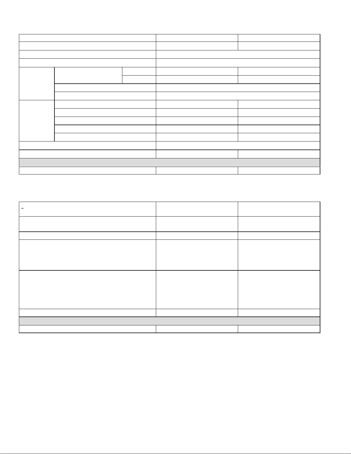
SPECIFICATIONS
Net face area
Outdoor
Outdoor
G
)
Fan(s)
Model No. HP29−090−2 HP29−120−2
Nominal Size − Tons (kW) 7.5 (26.4) 10 (35.2)
Liquid line (o.d.) in. (mm) connection (sweat) 5/8 (15.9)
Vapor line (o.d.) in. (mm) connection (sweat) 1−3/8 (34.9)
Outer coil 21.80 (2.03) (2) 29.34 (2.73)
Inner coil 20.94 (1.95) − − − −
Outdoor
Coil
Net face area
sq. ft. (m
2
)
Tube diameter in. (mm) & no. of rows 3/8 (9.5) − 2
Fins per inch (m) 20 (787)
Diameter in. (mm) & no. of blades (1) 24 (610) − 4 (2) 24 (610) − 3
Motor hp (W) (1) 1/2 (373) (2) 1/3 (249)
Coil
Fan(s)
Cfm (L/s) total air volume 5300 (2500) 8200 (3870)
Rpm 1075 1100
Motor Input − Watts 350 700
Refrigerant charge dry air
Shipping weight lbs. (kg) 1 package 506 (230) 604 (284)
OPTIONAL ACCESSORIES – Must Be Ordered Extra
Hail Guards 83K37 79K91
SPECIFICATIONS
General
Data
Connections
(sweat)
Refrigerant dry air holding charge dry air holding charge
Outdoor
Coil
Outdoor
Coil
Fan(s
Shipping lbs. (kg) 1 package 485 (220) 604 (284)
Liquid line (o.d.) − in. (mm) connection 5/8 (15.9) 5/8 (15.9)
Vapor line (o.d.) − in. (mm) connection 1−3/8 (34.9) 1−3/8 (34.9)
Net face area − sq. ft. (m2) Outer coil 30.0 (2.79) (2) 29.34 (2.73)
Tube diameter − in. (mm) & no. of rows 3/8 (9.5) − 2 3/8 (9.5) − 2
Diameter − in. (mm) & no. of blades (1) 24 (610) − 4 (2) 24 (610) − 3
Nominal Size − Tons (kW) 7.5 (26.4) 10 (35.2)
cfm (L/s) total air volume 5400 (2550) 8200 (3870)
Model No. HP29− 090−3 HP29−120−3
Inner coil 28.94 (2.69) − − −
Fins per inch (m) 20 (787) 20 (787)
Motor hp (W) (1) 3/4 (560) (2) 1/3 (249)
Rpm 1075 1100
Motor Input − Watts 600 700
OPTIONAL ACCESSORIES – Must Be Ordered Extra
Hail Guards 29M45 79K91
Page 2
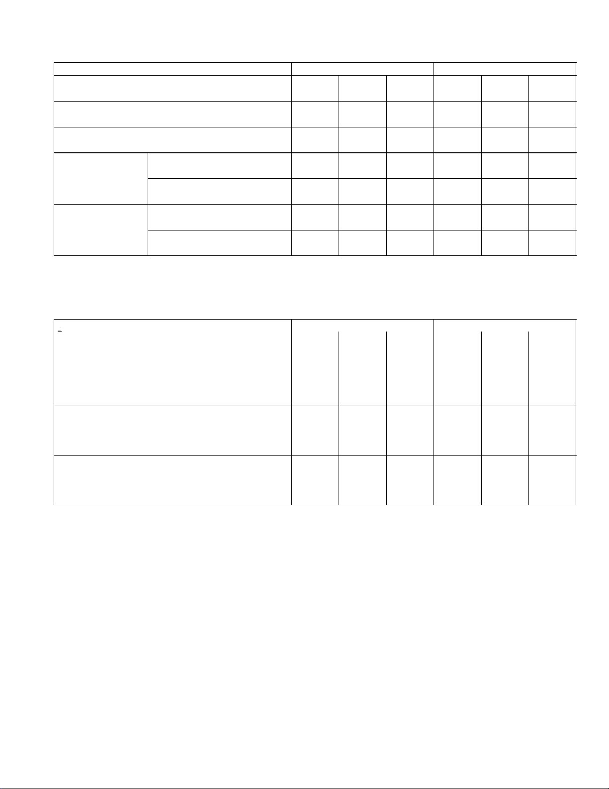
ELECTRICAL DATA
Outdoor Coil
G
FanMotor (1 phase)
Model No. HP29−090−2 HP29−120−2
Line voltage data 60 hz − 3 phase 208/230v 460v 575v 208/230v 460v 575v
Rec. max. fuse or circuit breaker size (amps) 60 30 25 80 40 25
{Minimum circuit ampacity 39 20 15 53 25 18
Rated load amps 28.8 14.7 10.8 37.8 17.2 12.4
Compressor (1)
Locked rotor amps 195 95 80 239 125 80
Full load amps (total) 3 1.5 1.2 2.4 (4.8) 1.3 (2.6) 1 (2)
FanMotor (1 phase)
{Refer to National or Canadian Electrical Code manual to determine wire, fuse and disconnect size requirements.
NOTE Extremes of operating range are plus and minus 10% of line voltage.
HACR type (under 100 amps). U.S. only.
Locked rotor amps (total) 6 3 2.9 4.7 (9.4) 2.4 (4.8) 1.9 (3.8)
ELECTRICAL DATA
General
Data
Line voltage data − 60 hz − 3 phase 208/230v 460v 575v 208/230v 460v 575v
Rec. max. fuse or circuit breaker size (amps) 60 35 25 80 40 25
{Minimum circuit ampacity 40 21 16 53 25 18
Compressor (1) Rated load amps 28.8 14.7 10.8 37.8 17.2 12.4
Outdoor Coil
{Refer to National or Canadian Electrical Code manual to determine wire, fuse and disconnect size requirements.
NOTE Extremes of operating range are plus and minus 10% of line voltage.
HACR type (under 100 amps). U.S. only.
Full load amps (total) 3.7 1.9 1.6 2.4 (4.8) 1.3 (2.6) 1 (2)
Locked rotor amps (total) 7.3 3.7 3.4 4.7 (9.4) 2.4 (4.8) 1.9 (3.8)
Model No. HP29−090−3 HP29−120−3
Locked rotor amps 195 95 80 239 125 80
Page 3
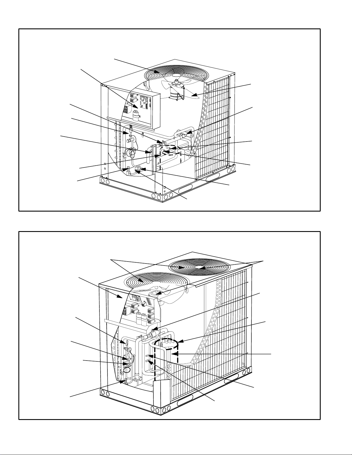
control box
vapor line
service valve
defrost thermostat
(S6)
HP29−090−3 MODEL PARTS ARRANGEMENT
fan guard
outdoor fan
(B4)
reversing
valve
discharge line thermostat
(S5)
compressor
(B1)
liquid line
service valve
control box
defrost pressure
loss of charge switch (S24)
low ambient switch
(S11)
FIGURE 1
HP29−120−3 MODEL PARTS ARRANGEMENT
fan guard
high pressure switch
(S4)
switch (S46)
outdoor fans
(B4, B5)
vapor line
service valve
defrost thermostat
(S6 [S124 not shown])
low ambient switch
(S11)
loss of charge switch
(S24)
liquid line
service valve
reversing
valve
compressor
(B1)
defrost pressure switch
(S46)
high pressure switch
(S4)
FIGURE 2
Page 4
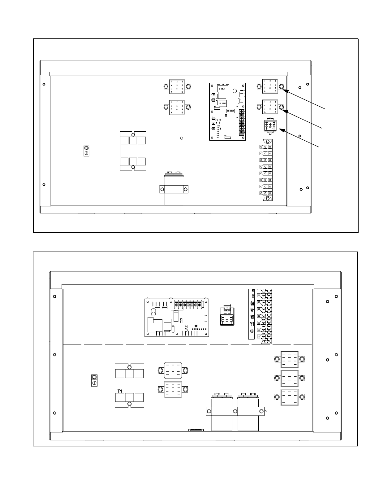
HP29−090−3 CONTROL BOX
transfer relay
K8
ground
lug
outdoor fan
relay K10
defrost/timer
capacitor C1
compressor
contactor
K1
FIGURE 3
HP29−120−3 CONTROL BOX
CMCI
terminal strip
TB 14
G1
W1
W2
Y1
low ambient
kit relay
K58
defrost relay
K4
R
G
C
latch relay
K6
ground
lug
compressor
contactor K1
cmc1 defrost / timer
outdoor fan
relay K10
outdoor fan
relay K68
low ambient
thermostat S41
FIGURE 4
relay switch
K6
capacitors
C1, C2
terminal strip
TB 14
transfer relay
K8
low ambient by−
pass realy
K58
defrost relay
K4
Page 5
I−UNIT COMPONENTS
The HP29−090 and HP29−120 components are shown in
figures 1 and 2.
A−CONTROL BOX COMPONENTS
The HP29−090 control box components are shown in fig
ure 3. The HP29−120P control box components are shown
in figure 4.
1 − Disconnect Switch S48
(Option −2 Units)
HP29 heat pumps units may be equipped with an optional
disconnect switch S48. S48 is a factory−installed toggle
switch used to disconnect power to the unit.
2 − Outdoor Fan Capacitors C1 (all units)
and C2 (120P)
All HP29 units use single−phase condenser fan motors.
Motors are equipped with a fan run capacitor to maximize
motor efficiency. Outdoor fan capacitors C1 and C2 assist
in the start up of condenser fan motors B4 and B5. Capaci
tor ratings are on outdoor fan motor nameplates.
3 − Compressor Contactor K1 (all units)
All compressor contactors are three−pole−double break
contactors with a 24V coil. K1 energizes compressor B1 in
both HP29−090 and HP29−120 units. The contactor is en
ergized from indoor thermostat terminal Y when thermo
stat demand is present.
4 − Low Ambient Thermostat S41
(HP29−120 only)
S41 is a N.C. limit which opens on temperature fall at 55+
5_F. The switch resets when temperature rises to 65+ 6_F.
S41 opens and de−energizes K68 which de−energizes out
door fan B5. When S41 closes, fans will be re−energi
zed.This intermittent fan operation increases indoor evap
orator coil temperature to prevent icing.
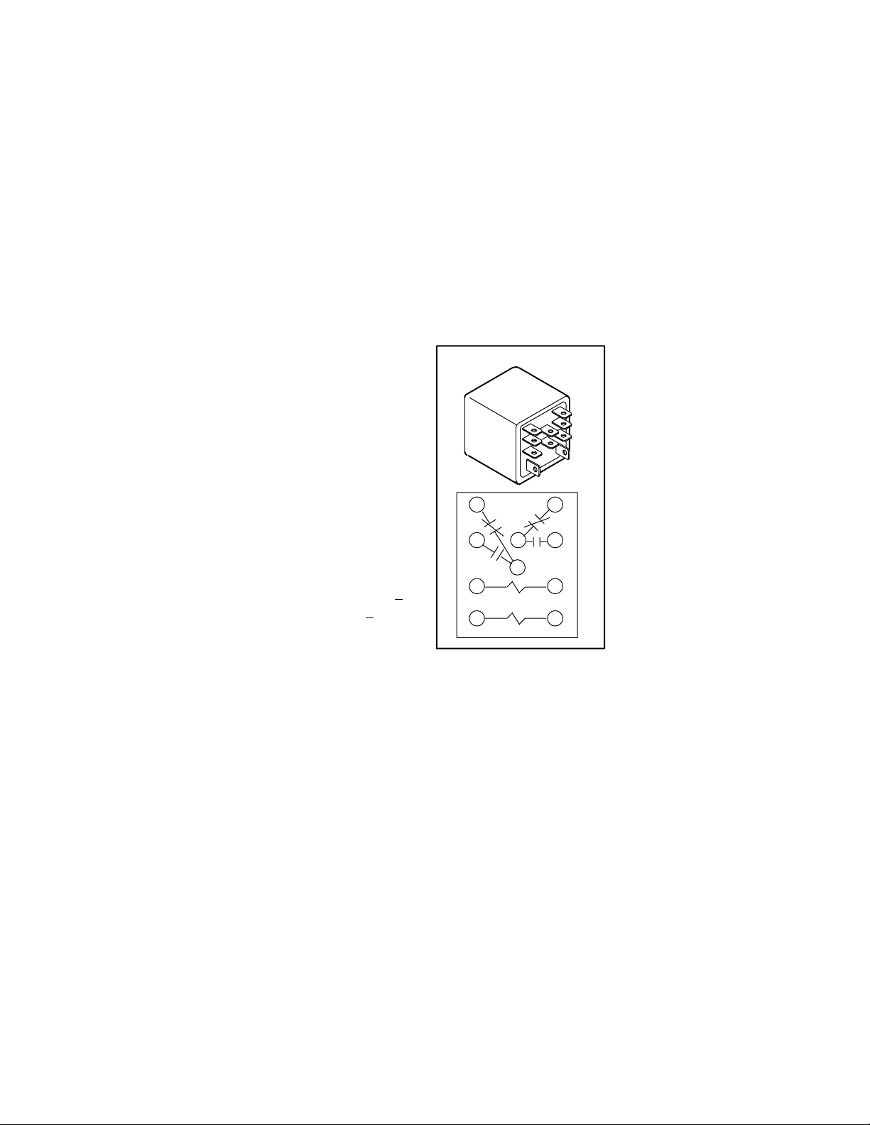
A latch relay (figure 5 ) has two coils: a SET" coil and a
RESET" coil. When 24VAC is applied to the SET" coil, the
normally open contacts close and the normally closed con
tacts open. When power is removed from the SET" coil,
nothing happens; the NO. contacts remain closed and the
N.C. contacts remain open. The contacts do not return to
their normal position until the RESET" coil is energized.
Once the contacts are reset, they remain in their normal
position when power is removed.
HP29 units use a DPDT
latch relay. Each set of nor
LATCH RELAY K6
14
568
10
9
RESET
13 14
FIGURE 5
mains in the cooling mode.
12
SET
mally open contacts con
trols a reversing valve.
When the SET" coil is en
ergized, the normally open
contacts close to energize
the reversing valve (there
by placing the unit in the
cooling mode). When pow
er is removed from the
SET" coil (such as when
thermostat demand is satis
fied), the normally open
contacts remain closed, the
reversing valve remains en
ergized and the unit re
5 − Latch Relay K6 (all units)
HP29 units are plumbed so that the unit is in cooling mode
when the reversing valve is energized. Latch relay K6 con
trols operation of the reversing valve and is controlled (indi
rectly) by the indoor thermostat. The combined operation
of latch relay K6 and transfer relay K8 allows the HP29
heat pumps to use a conventional heat/cool thermo
stat instead of a heat pump thermostat.
When a heating demand is initiated, the RESET" coil is
energized. The normally open contacts open and the re
versing valve is deenergized (thereby placing the unit in
the heating mode). When heat demand is satisfied and
power to the RESET" coil is removed, the normally open
contacts remain open, the normally closed contacts re
main closed and the unit remains in the heating mode.
Page 6
6 − Transfer Relay K8 (all units)
Transfer relay K8 ensures that the indoor blower will oper
ate during all modes of operation. K8 also completes the
circuit to Y1 on the defrost control board CMC1. The com
bined operation of latch relay K6 and transfer relay K8 al
lows the HP29 unit to use a conventional heat/cool thermo
stat instead of a heat pump thermostat. When there is a de
mand for cooling, K8−1 closes completing the Y1 circuit to
defrost control board CMC1 terminal Y1. Normally open
K6−1 closes energizing the reversing valve. K8−2 normaly
closed contacts ensure an unbroken circuit between in
door thermostat "G" and indoor blower contactor through
terminals "G" and "G1" on terminal strip TB14. When there
is a heat demand, normally closed K8−1 opens breaking
the Y1 circuit to the defrost control CMC1. Power is sent to
the "RESET" coil on K6. K6−1 opens de−energizing the re
versing valve. K8−2 closes sending voltage from "G1" to
the indoor blower control.
7 − Outdoor Fan Relay K10 (all units)
K68 (HP29−120)
Outdoor fan relay K10 is a DPDT relay and K68 is a SPDT
relay with a 24V coil. In all units K10 energizes outdoor fan
B4 (fan 1) in response to thermostat demand. In the
HP29−120, K68 energizes outdoor fan B5 (fan 2) in re
sponse to thermostat demand.
8 − Terminal Strip TB14 (all units)
TB14 terminal strip distributes 24V power from the thermo
stat to control box components.
9 − Low Ambient Bypass Relay K58
(all units)
K58 is a normally closed DPDT relay with a 24V coil, used
in both HP29−090 and HP29−120 units. K58 is wired paral
lel with the reversing valve L1. When L1 is energized in the
cooling cycle, K58 is also energized, opening K58−1. On
the HP29−120, K58−1 and K58−2 will open. This shuts off
power to the outdoor fans but does not by−pass S11 and
S41, which allow fans to cycle during cooling demand. Dur
ing heating demand, K58 remains closed by−passing S11
and S41 so fans can operate.
10 − GFI− J11 (Optional −2 units)
HP29 units may be equipped with a 110v ground fault in
terrupter (GFI). The GFI is located on the control box panel
on the HP29. Separate wiring must be run for the 110v re
ceptacle.
B−COOLING COMPONENTS
IMPORTANT
ALL major components (indoor blower/coil) must
be matched to Lennox recommendations for com
pressor to be covered under warranty. Refer to En
gineering Handbook for approved system match
ups.
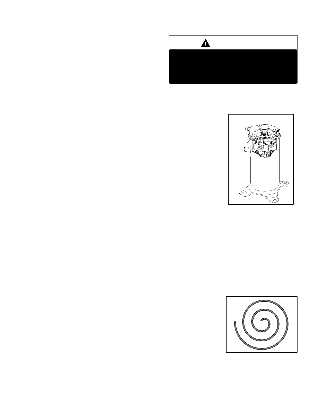
1 − Scroll Compressor B1
All HP29 units utilize a
scroll compressor. The
scroll compressor design
is simple, efficient and re
quires few moving parts.
A cutaway diagram of the
scroll compressor is
shown in figure 6. The
scrolls are located in the
top of the compressor can
and the motor is located in
the bottom of the com
pressor can. The oil level
is immediately below the
motor and oil is pressure
fed to the moving parts of the compressor. The lower portion
of the compressor shell is exposed to low side pressure while
only the very top of the shell is exposed to high side pressure.
The scroll is a simple compression concept centered
around the unique spiral shape of the scroll and its inherent
properties. Figure 7 shows the basic scroll form. Two iden
tical scrolls are mated together forming concentric spiral
shapes (figure 9). One
scroll remains station
ary, while the other is al
lowed to orbit (figure
8−1). Note that the orbit
ing scroll does not rotate
or turn but merely orbits
the stationary scroll.
SCROLL COMPRESSOR
DISCHARGE
SUCTION
FIGURE 6
Page 7
FIGURE 7
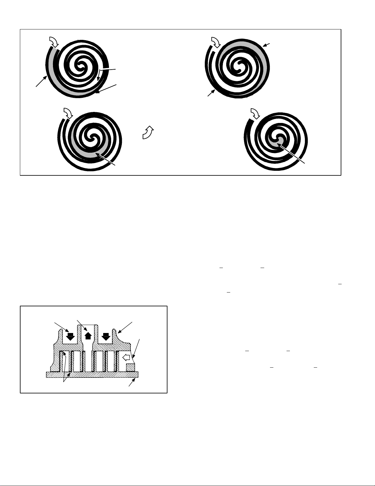
SUCTION
1
SUCTION
POCKET
SUCTION
ORBITING SCROLL
STATIONARY SCROLL
MOVEMENT OF ORBIT
SUCTION
2
FLANKS SEALED
BY CENTRIFIGUAL
FORCE
INTERMEDIATE PRESSURE
GAS
CRECENT SHAPED
GAS POCKET
SUCTION
3
The counterclockwise orbiting scroll draws gas into the
outer crescent shaped gas pocket created by the two
scrolls (figure 8−2). The centrifugal action of the orbiting
scroll seals off the flanks of the scrolls (figure 8−3). As the
orbiting motion continues, the gas is forced toward the cen
ter of the scroll and the gas pocket becomes compressed
(figure 8−4).
When compressed gas reaches the center, it is discharged
vertically into a chamber and discharge port in the top of
the compressor (figure 6). The discharge pressure forcing
down on the top scroll helps seal the upper and lower
edges (tips) of the scrolls (figure 9). During a single orbit,
several pockets of gas are compressed simultaneously
providing smooth continuous compression.
CROSS−SECTION OF SCROLLS
DISCHARGE
PRESSURE
TIPS SEALED BY
DISCHARGE PRESSURE
DISCHARGE
ORBITING SCROLL
FIGURE 9
HIGH PRESURE GAS
STATIONARY SCROLL
SUCTION
4
FIGURE 8
2 − Crankcase Heaters HR1 (all units)
All HP29 units use a belly−band crankcase heater. Heater
HR1 is wrapped around compressor B1. HR1 assures
proper compressor lubrication at all times.
3 − High Pressure Switch S4 (all units)
The high pressure switch is a manual−reset SPST N.C.
switch which opens on a pressure rise. The switch is lo
cated on the compressor discharge line and is wired to the
defrost control board CMC1. When discharge pressure
rises to 450 + 10 psig (3103 + 69 kPa) the switch opens and
the compressor is de−energized through the CMC1. The
switch will close when discharge pressure drops to 300 +
20 psig (2068 + 138 kPA).
4 − Low Ambient Switch S11 (all units)
The low ambient switch is an auto−reset SPST N.O. pres
sure switch, which allows for mechanical cooling operation
at low outdoor temperatures. All HP29 units are equipped
with S11. The switch is located in the liquid line. In all HP29
units, S11 is wired in series with fan relay K10. When liquid
pressure rises to 275 + 10 psig (1896 + 69 kPa), the switch
closes and the condenser fan is energized. When the dis
charge pressure drops to 150 + 10 psig (1034 + 69 kPa),
the switch opens and the condenser fan is de−energized.
This intermittent fan operation results in higher evaporat
ing temperature, allowing the system to operate without ic
ing the evaporator coil and losing capacity.
DISCHARGE
POCKET
Page 8
5 − Discharge Line Thermostat S5
S5 is an automatic reset SPST N.C. switch which opens on
a temperature rise. The switch is located on the discharge
line and wired in series with the CMCI board and S4 pres
sure switch. When discharge line temperature rises to
275° + 5°F the switch opens and the compressor is de−en
ergized through the CMCI. The switch automatically resets
when discharge temperature drops to 225° +
5°F.
6 − Loss of Charge Switch S24
The loss of charge switch is an auto−reset SPST N.O.
switch, which opens on pressure drop. The switch is lo
cated on the liquid line and is wired to the defrost control
board CMC1. When liquid pressure drops to 25 + 5 psig
(172 + 34 kPa), the switch opens and the compressor is de−
energized. The switch automatically resets when pressure
in the liquid line rises to 55 + 5 psig (379 + 34 kPa).
7 − Reversing Valve L1 (all units)
A reversing valve with an electromechanical solenoid is
used to reverse refrigerant flow during unit operation. L1 is
energized during cooling demand and defrost. See figures
12 and 13.
8 − Expansion Valves
The HP29−120−2 uses two expansion valves in the liquid
line adjacent to the left and right refrigerant coil. The
HP29−090−2 units have one expansion valve. Aliquid line
filter/drier and check valve are connected in parallel with
each expansion valve. The check valve allows for reverse
refrigerant flow. The HP29−120−3 uses two internally
checked expansion valveand the HP29−090−3 uses one in
ternally checked expansion valve. The valves are located
in the liquid line adjacent to the left and right refrigerant coil.
In all units expansion valve control is provided by a super
heat sensing bulb which is connected by a capillary tube to
the expansion valve. The sensing bulb is strapped to the
vapor line where it exits the coil. If the bulb senses low su
perheat, the expansion valve throttles down and restricts
refrigerant flow through the coil. When excessive super
heat is sensed, the valve opens to allow more refrigerant
flow through the coil. See figures 12 and 13.
9 − Condenser Fan B4 (both units)
B5 (HP29−120)
See page 2 for the specifications on the condenser fans
used in the HP29 units. All condenser fans have single−
phase motors. The HP29−090 units are equipped with a
single condenser fan. The HP29−120 is equipped with two
fans. The fan assembly may be removed for servicing by
removing the motor mounts nuts.
C−Defrost System
ELECTROSTATIC DISCHARGE (ESD)
Precautions and Procedures
CAUTION
Electrostatic discharge can affect electronic
components. Take precautions during unit instal
lation and service to protect the unit’s electronic
controls. Precautions will help to avoid control
exposure to electrostatic discharge by putting
the unit, the control and the technician at the
same electrostatic potential. Neutralize electro
static charge by touching hand and all tools on an
unpainted unit surface before performing any
service procedure.
The defrost system includes four components: a defrost
thermostat, defrost pressure switch, defrost relay and de
frost control.
Defrost Thermostat Switch S6, S124
Defrost thermostat switches S6 (refrigeration circuit one)
and S124 (refrigeration circuit two) are S.P.S.T. N.O. con
tacts which close on temperature fall (initiating defrost after
minimum run time of 30, 60, or 90 minutes). The switches
are located on each of the expansion valve distributor as
semblies. The switches monitor the outdoor coil saturation
temperature to determine when defrost is needed. When
the outdoor coil temperature falls to 35_ F+ 4_F (1.7_C +
2.2_C), the switch closes (initiating defrost after minimum
run time of 30, 60, or 90 minutes). When the temperature
rises to 60_F + 5_F (15.6_C + 2.8_C), the switch opens.
Defrost Pressure Switch S46
Defrost switch S46 is an auto−reset SPST N.C. pressure
switch which opens on pressure rise of 275 + 10 psi (1896
+ 69 kPa). When S46 opens, defrost operation ends. The
switch will reset when the unit receives a heat call and
pressure falls to 195 + 10 psi (1344 + 69 kPa). All HP29
units are equipped with this switch located on the dis
charge line. See figures 1 and 2. S46 is wired through the
K8 transfer relay to the defrost board CMC1.
Defrost Relay K4
Defrost relay K4 controls defrost in the HP29 units. K4 is
controlled by defrost board CMC1 and defrost pressure
switch S46. When K4 is energized, contacts close and de
frost is initiated.
Page 9
 Loading...