

HP27
Netfacearea
Coil
Fan
p
Outdoor Coil
Corp. 9621−L10
Service Literature
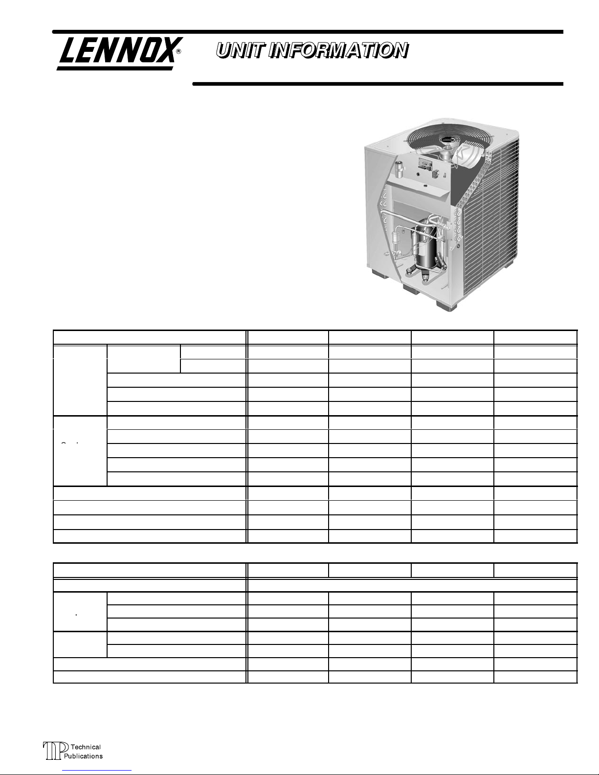
HP27 SERIES UNITS
The HP27 is a high efficiency residential split−system heat
pump which features a scroll compressor. It operates
much like a standard heat pump, but the scroll compressor
is unique in the way that it compresses refrigerant. Several
models are available in sizes ranging from 2 through 3-1/2
tons. The series uses expansion valves in the outdoor unit
and in the indoor unit.
This manual is divided into sections which discuss the major components, refrigerant system and charging procedures, maintenance and operation sequences. All specifications in this manual are subject to change.
Model No. HP27−024 HP27−030 HP27−036 HP27−042
Netfacearea
sq. ft. (m2)
Condenser
Condenser
Fan
Refrigerant furnished (HCFC-22) 12 lbs. 5 oz. (5.6 kg) 11 lbs. 5 oz. (5.1 kg) 11 lbs. 13 oz. (5.3 kg) 12 lbs. 12 oz. (5.8 kg)
Liquid line conn. o.d. in. (mm) (sweat) 3/8 (9.5) 3/8 (9.5) 3/8 (9.5) 3/8 (9.5)
Vapor line conn. o.d. in. (mm) (sweat) 3/4 (19) 3/4 (19) 7/8 (22.2) 7/8 (22.2)
Shipping wt. lbs. (kg) 1 package 268 (122) 271 (123) 328 (149) 328 (149)
Refrigerant charge sufficient for 15 ft. (4.5 m) length of refrigerant lines.
Line voltage data 208/230v 60hz−1ph
Compressor
Outdoor Coil
Fan Motor
Rec. max. fuse or circuit breaker size (amps) 20 25 30 40
Minimum circuit ampacity 13.8 16.2 17.8 23.4
Refer to National or Canadian Electrical Code manual to determine wire, fuse and disconnect size requirements.
NOTE Extremes of operating range are plus 10% and minus 5% of line voltage.
Tubediameter in. (mm) 5/16 (7.9) 5/16 (7.9) 5/16 (7.9) 5/16 (7.9)
No. of rows 2 2 2 2
Fins per inch (m) 22 (866) 22 (866) 22 (866) 22 (866)
Diameter in. (mm) No. of blades 24( 610) − 3 24( 610) − 3 24( 610) − 3 24( 610) − 3
Motor hp (W) 1/10 (75) 1/10 (75) 1/10 (75) 1/10 (75)
Cfm (L/s) 2800 (1320) 2800 (1320) 2800 (1320) 2800 (1320)
Rpm 825 825 825 825
Watts 165 165 170 170
Model No. HP27−024 HP27−030 HP27−036 HP27−042
Rated load amps 10.26 12.18 13.46 18.0
Power factor 0.96 0.96 0.96 0.97
Locked rotor amps 56 61 73 104
Full load amps 0.9 0.9 0.9 0.9
Locked rotor amps 1.6 1.6 1.6 1.6
Outer Coil 21.77 (2.02) 21.77 (2.02) 24.06 (2.24) 24.06 (2.24)
Inner Coil 21.11 (1.96) 21.11 (1.96) 23.33 (2.17) 23.33 (2.17)
Revised 08−2004
SPECIFICATIONS
ELECTRICAL DATA
Page 1
© 1997 Lennox Industries Inc.
Litho U.S.A.
DISCHARGE
SUCTION
SCROLL COMPRESSOR
CROSS−SECTION OF SCROLLS
DISCHARGE
DISCHARGE
PRESSURE
SCROLL FORM
FIGURE 2
STATIONARY SCROLL
SUCTION
FIGURE 1
I−APPLICATION
All major components (indoor blower/coils) must be
matched according to Lennox recommendations for the
compressor to be covered under warranty. Refer to the
Engineering Handbook for approved system matchups. A
misapplied system will cause erratic operation and can result in early compressor failure.
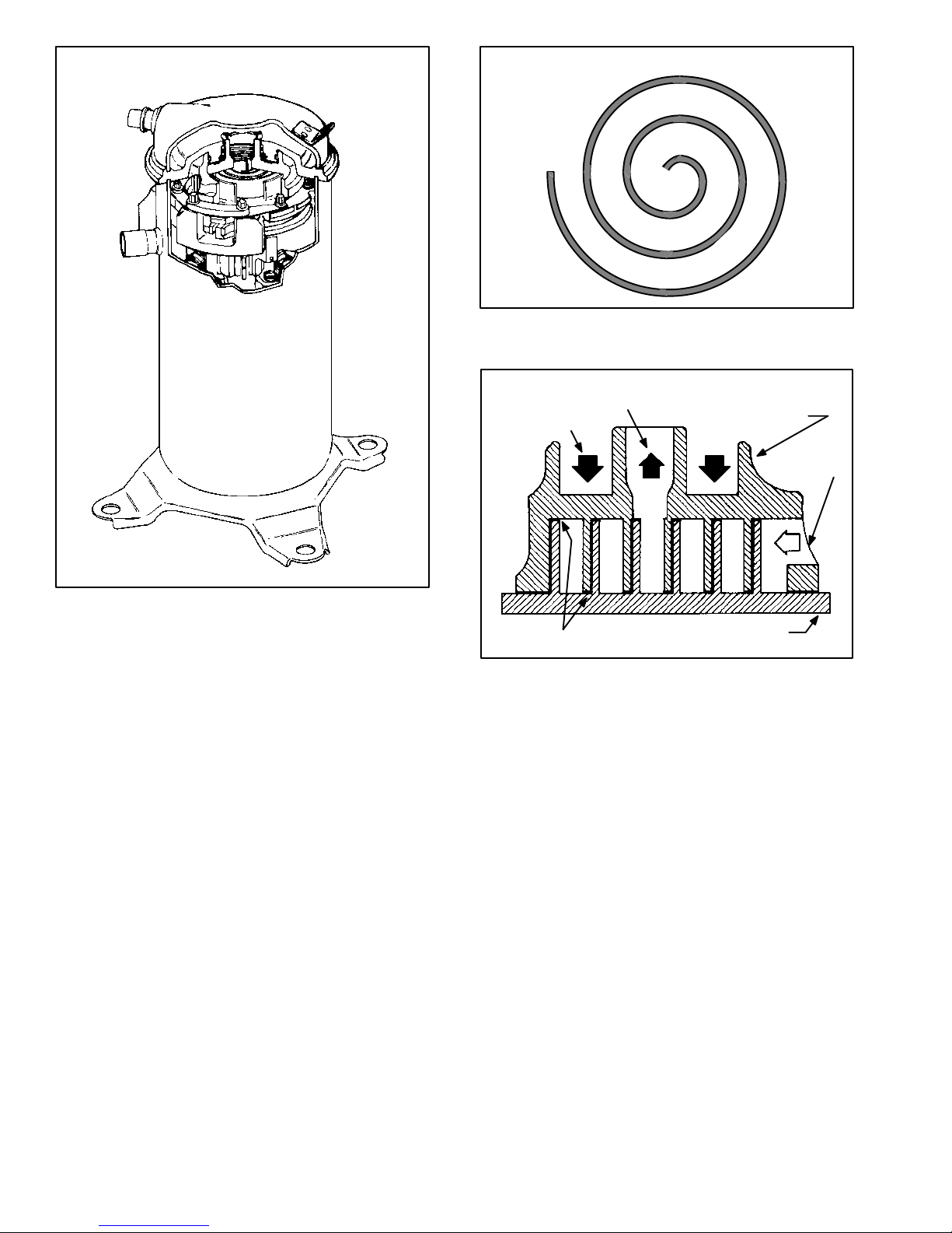
II−SCROLL COMPRESSOR
The scroll compressor design is simple, efficient and requires few moving parts. A cutaway diagram of the scroll
compressor is shown in figure 1. The scrolls are located in
the top of the compressor can and the motor is located in
the bottom of the compressor can. The oil level is immediately below the motor.
The scroll is a simple compression concept centered
around the unique spiral shape of the scroll and its inherent properties. Figure 2 shows the basic scroll form. Two
identical scrolls are mated together forming concentric
spiral shapes (figure 3). One scroll remains stationary,
while the other is allowed to "orbit" (figure 4). Note that the
orbiting scroll does not rotate or turn but merely orbits the
stationary scroll.
NOTE − The head of a scroll compressor may be hot since
it is in constant contact with discharge gas.
TIPS SEALED BY
DISCHARGE PRESSURE
ORBITING SCROLL
FIGURE 3
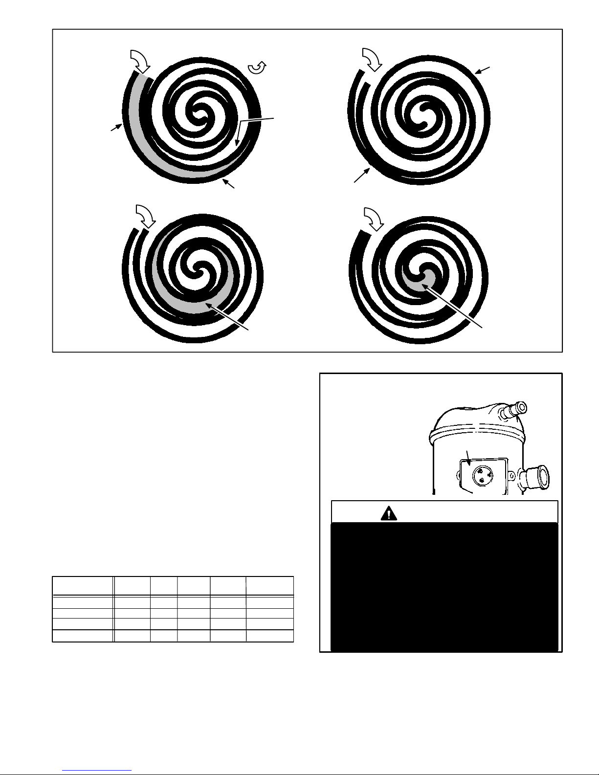
The counterclockwise orbiting scroll draws gas into the outer crescent shaped gas pocket created by the two scrolls
(figure 4 − 1). The centrifugal action of the orbiting scroll
seals off the flanks of the scrolls (figure 4 − 2). As the orbiting motion continues, the gas is forced toward the center of
the scroll and the gas pocket becomes compressed (figure
4 − 3). When the compressed gas reaches the center, it is
discharged vertically into a chamber and discharge port in
the top of the compressor (figure 1). The discharge pressure forcing down on the top scroll helps seal off the upper
and lower edges (tips) of the scrolls (figure 3). During a
single orbit, several pockets of gas are compressed simultaneously providing smooth continuous compression.
The scroll compressor is tolerant to the effects of liquid return. If liquid enters the scrolls, the orbiting scroll is allowed to separate from the stationary scroll. Continued
slugging of liquid will cause damage to the scroll and replacement will be necessary. The liquid is worked toward
the center of the scroll and is discharged. If the compressor is replaced, conventional Lennox cleanup practices
must be used.
Page 2
SUCTION
POCKET
HOW A SCROLL WORKS
SUCTION
MOVEMENT OF ORBIT
ORBITING
SCROLL
SUCTION
INTERMEDIATE
PRESSURE
GAS
CRESCENT
SHAPED GAS
POCKET
12
FLANKS
STATIONARY SCROLL
SUCTION
SEALED BY
CENTRIFUGAL
FORCE
SUCTION
34
HIGH
PRESSURE
GAS
FIGURE 4
III−UNIT COMPONENTS
A−Transformer
The contactor, reversing valve, time delay, and defrost timer are all powered by 24VAC supplied by the indoor unit.
All other controls in the outdoor unit are powered by line
voltage. Refer to unit wiring diagram. The HP27 is not
equipped with an internal line voltage to 24V transformer.
B−Terminal Strip
All HP27s are equipped with a low voltage terminal strip
located in the unit control box for making thermostat wiring
connections (refer to figure 6).
C−Compressor
Table 1 shows the specifications of compressors (B1)
used in HP27 series units.
TABLE 1
Unit Phase LRA RLA
*Shipped with conventional white oil (Sontex 200LT). 3GS oil may be
used if additional oil is required.
Vac
208/230HP27−024 56 10.3 38
208/230
208/230
208/230
1
1HP27−030
61 42
1HP27−036
73
1HP27−042
12.2
13.5
18.0104
Oil
fl.oz.
42
42
DISCHARGE
POCKET
COMPRESSOR TERMINAL BOX
COMPRESSOR
TERMINALS
C
S
R
WARNING
COMPRESSOR MUST BE GROUNDED. DO
NOT OPERATE WITHOUT PROTECTIVE COVER
OVER TERMINALS. DISCONNECT ALL POWER
BEFORE REMOVING PROTECTIVE COVER.
DISCHARGE CAPACITORS BEFORE SERVICING UNIT. COMPRESSOR WIRING DIAGRAM IS FURNISHED INSIDE COMPRESSOR
TERMINAL BOX COVER. FAILURE TO FOLLOW
THESE PRECAUTIONS COULD CAUSE ELECTRICAL SHOCK RESULTING IN INJURY OR
DEATH.
FIGURE 5
Page 3
DUAL CAPACITOR
TXV
SENSING BULB −036,
−042 ONLY
HIGH PRESSURE
SWITCH
BIFLOW FILTER/DRIER
EXPANSION VALVE
WITH
INTERNAL CHECK
VALV E
DEFROST
THERMOSTAT
DISTRIBUTOR
ACCUMULATOR
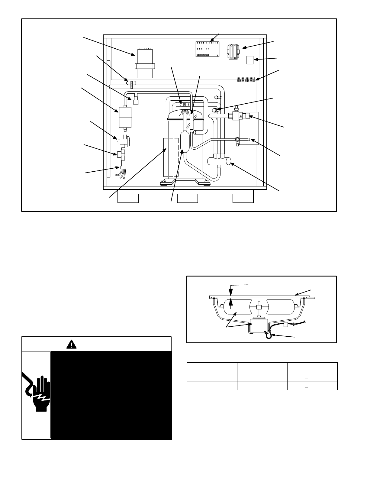
HP27 UNIT COMPONENTS
DEFROST CONTROL/TIMED−OFF CONTROL
TXV
SENSING BULB
−024, −030 ONLY
THERMOMETER WELL
MUFFLER
CONTACTOR
GROUND LUG
TERMINAL STRIP
SUCTION
GAUGE
PORT
VAPOR LINE
SERVICE VALVE
AND GAUGE
PORT
LIQUID LINE
SERVICE VALVE
AND GAUGE
PORT
REVERSING
VALV E
AND SOLENOID
D−High Pressure Switch
An automatic reset high pressure switch (S4) located in the
liquid line of the compressor shuts off the compressor when
liquid line pressure rises above the factory setting. The switch
is normally closed and is permanently adjusted to trip (open)
at 410 + 10 psi. The switch closes at 210 + 10 psi. See figure 6
for switch location.
E−Contactor
The compressor is energized by a contactor (K1) located
in the control box. Units will use single−pole or double−pole
contactors. See wiring diagrams for specific unit. The contactor is energized by indoor thermostat terminal Y when
thermostat demand is present.
DANGER
Electric Shock Hazard.
May cause injury or death.
Disconnect all remote electrical power
supplies berore opening unit panel. Unit
may have multiple power supplies.
FIGURE 6
F−Condenser Fan Motor
See page 1 for specifications for all condenser fan motors
(B4) used. See figure 7 if condenser fan motor replacement is necessary. In all units, the condenser fan motor is
controlled by the compressor contactor and is de−energized when the defrost relay is energized.
"A" SEE TABLE 2
Condenser fan
and motor
FAN GUARD
Wiring
Drip loop
FIGURE 7
TABLE 2
UNIT "A" DIM. TOLERANCE
HP27−024, −030 1 1/16" + 1/8"
HP27−036, −042 1 3/16" + 1/8"
Some units are equipped with single−
pole contactors. When unit is equipped
with a single−pole contactor, line voltage
is present at all components (even when
unit is not in operation).
G−Accumulator
The accumulator is located on the liquid line (see figure 6.)
The accumulator retains liquid and releases mostly vapor
to the compressor. This ensures that the liquid refrigerant
will not enter and damage the compressor.
Page 4

H−Service Light Thermostat HP27
HP27−1 through −7 units are equipped with a service light
thermostat (S54) located on the compressor discharge
line. The switch is electrically connected to the service
light in the indoor thermostat. The service light, when lit,
indicates the compressor is not running. The service light
is powered from W1 (2nd stage heat) terminal of the indoor
thermostat. The service light thermostat will close when
the discharge line falls below 110 + 5F, indicating a problem in the system. The service light thermostat opens and
the service light goes off when discharge line reaches 130
+ 5F indicating the compressor is running.
I−Ambient Compensating Thermistor
HP27−1 through −7 units have an ambient compensating
thermistor (RT3) mounted on the outdoor fan wiring harness. The thermistor is an NTC thermistor (negative temperature coefficient − increase in temperature equals decrease in resistance) (see figure 8). The device is connected in series with the heat anticipation resistor inside the
indoor thermostat. This feature helps to prevent abnormal
droop caused by the anticipation resistors. As outdoor temperature increases, the resistance across the thermistor
drops. As the resistance across the thermistor drops, the
current through the heat anticipation resistor increases.
Therefore, heat anticipation increases as outdoor temperature decreases. Resistance at 77F = 260 ohms + 5%; at
100F = 150 ohms; at 32F = 861 ohms.
TABLE 3
HP27 DUAL CAPACITOR RATING
UNITS FAN MFD HERM MFD VAC
HP27−024 4 40 370
HP27−030 4 40 370
HP27−036 4 45 370
HP27−042 4 55 370
K−Reversing Valve and Solenoid
A refrigerant reversing valve (L1) with electromechanical
solenoid is used to reverse refrigerant flow during unit operation. The reversing valve is energized during cooling
demand and during defrost.
L−Defrost System HP27−1, −2, −3 and −5 units
ELECTROSTATIC DISCHARGE (ESD)
Precautions and Procedures
CAUTION
Electrostatic discharge can affect electronic
components. Take precautions during unit
installation and service to protect the unit’s
electronic controls. Precautions will help to
avoid control exposure to electrostatic discharge by putting the unit, the control and the
technician at the same electrostatic potential.
Neutralize electrostatic charge by touching
hand and all tools on an unpainted unit surface
before performing any service procedure.
OUTDOOR FAN, BRACKET AND
AMBIENT COMPENSATING
THERMISTOR
OUTDOOR FAN
FAN MOTOR
BRACKET
FIGURE 8
J−Dual Capacitor
The compressor and fan in the HP27 series units use permanent split capacitor motors. A single dual capacitor
(C12) is used for both the fan motor and the compressor
(see unit wiring diagram). The fan side of the capacitor
and the compressor side of the capacitor have different
mfd ratings. The capacitor is located inside the unit control
box (see figure 6). Table 3 shows the ratings of the dual capacitor.
The defrost system includes two components: a defrost
thermostat (S6) and a defrost control.
Defrost Thermostat
The defrost thermostat is mounted on the liquid line between the check/expansion valve and the distributor. When
defrost thermostat senses 35F (2C) or cooler, its contacts close and send a signal to the defrost control board to
start the defrost timing. It also terminates defrost when the
liquid line warms up to 70F (21C).
Defrost Control
The defrost control board has the combined functions
of a time/temperature defrost control, defrost relay,
time delay, diagnostic LEDs and field connection terminal strip. See figure 9.
The control provides automatic switching from normal
heating operation to defrost mode and back. During compressor cycle (room thermostat demand cycle), if the O"
input is not on and the defrost thermostat is closed, the
control accumulates compressor run times at 30, 60 or 90
minute field adjustable intervals. If the defrost thermostat
remains closed when the accumulated compressor run
time ends, the defrost relay is energized and defrost begins.
Page 5
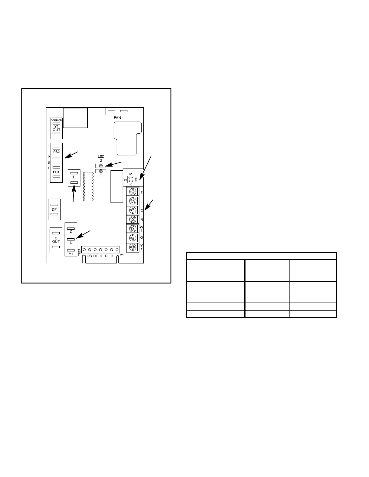
Defrost Control Timing Pins
Each timing pin selection provides a different accumulated compressor run period during one thermostat run
cycle. This time period must occur before a defrost cycle
is initiated. The defrost interval can be adjusted to 30, 60
or 90 minutes. See figure 9. The defrost period is a maximum of 14 minutes and cannot be adjusted. If no timing
is selected, the control defaults to 90 minutes.
DEFROST CONTROL BOARD
NOTE − COMPONENT LOCATIONS WILL VARY
WITH BOARD MANUFACTURER
PRESSURE SWITCH
SAFETY CIRCUIT
CONNECTIONS
DIAGNOSTIC
LEDs
AMBIENT
THERMISTOR
CONNECTION
SERVICE LIGHT
CONNECTION
NOTE− There is an internal jumper between
inside PS1 and PS2 terminals.
FIGURE 9
A TEST option is provided for troubleshooting. When the
jumper is placed across the TEST pins, the timing of all
functions is reduced by a factor of 128. For example, a 30
minute interval during TEST is 14 seconds and the 14 minute defrost is reduced to 6.5 seconds.
The TEST mode may be started at anytime. If the jumper is
in the TEST position at power−up or for longer than five minutes, the control will ignore the TEST selection and will default to a 90 minute interval. In order to test defrost cycle,
defrost thermostat must be closed or jumpered. Once defrost is initiated, remove jumper immediately. Failure to remove jumper will reduce defrost cycle to seconds.
DEFROST
INTERVAL
TIMING PINS
24V TERMINAL
STRIP
CONNECTIONS
Time-Delay
A 5-minute timed-off delay protects the compressor from
short-cycling when there is an interruption in power to the
unit or when a pressure switch resets.
Pressure Switch Safety Circuits
The defrost control incorporates a safety circuit that allows
the application of an additional pressure switch. The unit’s
high pressure switch (S4) is factory-wired into this circuit.
See figure 9. PS1 and PS2 terminals are wired in series
with a jumper internal to the control board. This feature is
available on all units.
During one demand cycle, the defrost control will lock out
the unit on the third instance that the unit goes off on any
auto−reset pressure switch wired to this circuit. In addition,
the diagnostic LEDs will indicate a locked out pressure
switch after the third occurrence of an open pressure
switch. See table 4. The unit will remain locked out until 24
volt power is broken to terminal R" on the defrost board
and then remade.
The PS2 safety circuit terminals are connected to the compressor thermostat. An optional loss of charge switch may
be field-installed by connecting it in series with the other
switches. See unit wiring diagram.
Diagnostic LEDs
The defrost board uses two LEDs for diagnostics. The
LEDs flash a specific sequence according to the condition.
TABLE 4
DEFROST CONTROL BOARD DIAGNOSTIC LED
MODE LED 1 LED 2
Normal Operation/
Power to board
Time Delay
To Protect Compressor
Pressure Switch Open Off On
Pressure Switch Lockout On Off
Board Malfunction On On
Flash together with
LED 2
Alternating Flashes
with LED 2
Flash together with
LED 1
Alternating Flashes
with LED 1
Ambient Thermistor & Service Light Connection
The defrost control board provides terminal connections
for the ambient thermistor and a service light. The thermistor compensates for changes in ambient temperature
which might cause thermostat droop. The service light
thermostat provides a signal which activates the room
thermostat service light during periods of inefficient operation.
Page 6
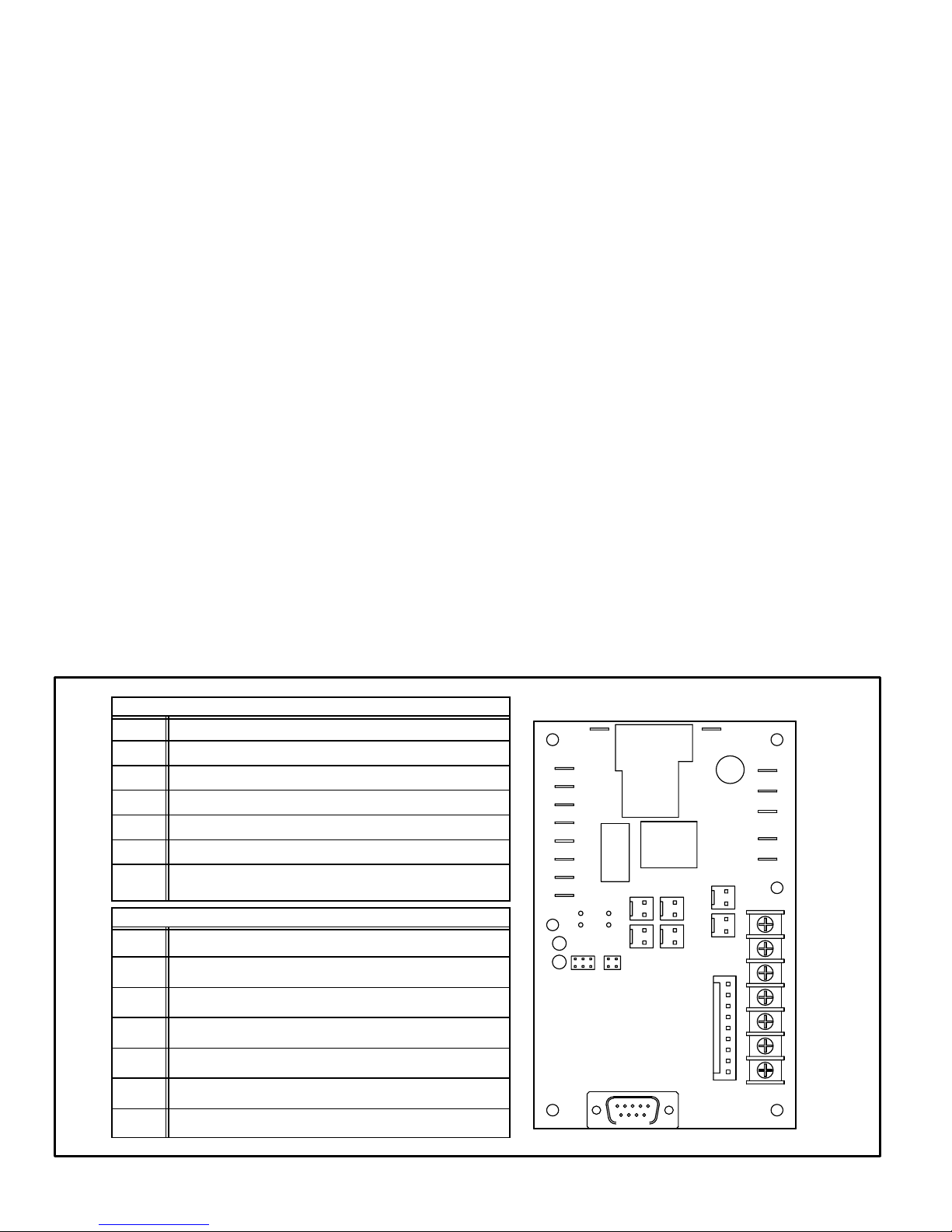
M−Defrost System HP27−4 and −6 ONLY
HP27−4 and −6 units are equipped with a demand defrost
system. The self−calibrating defrost control board includes
defrost relays, sensors (two) which monitor coil and out-
door ambient temperatures, a timed−off control, protection
circuits (two), a 3−strike lockout feature, a test mode jump-
er and a terminal strip. The demand defrost control board
initiates a defrost cycle based on temperature differential
and compressor run time. This type of system allows
greater frost accumulation on the outdoor coil and initiates
fewer defrost cycles than the time/temperature defrost
system. The defrost board is shown in figure 10.
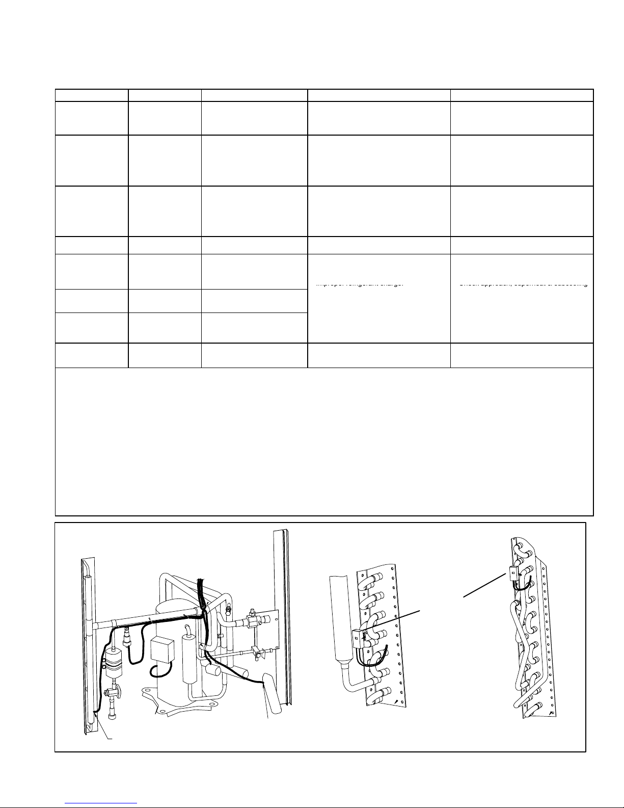
Temperature Sensors
The demand defrost control board includes two perma-
nently attached sensors which monitor coil and outdoor
ambient temperatures. The coil temperature sensor is
equipped with a spring clip to allow proper positioning on
the outdoor coil. These sensors must not be detached
from the control board and must be replaced as part of the
control board. Do not attempt to cut or splice the tempera-
ture sensor wires. See figure 11 for ambient and coil tem-
perature sensor location.
Timed−Off Control
The control board includes a 5−minute timed−off delay
which protects the compressor from short cycling. The
5−minute delay is initiated at the end of a compressor
cycle, any time a system protection switch is reset, or if the
Y1 circuit is interrupted for more than two continuous line
cycles.
If a system protection switch opens while the Y1 OUT" circuit is energized, the timed−off control will initiate a 5−minute delay when the pressure switch closes.
The timed−off control run times can be bypassed by
shorting the TEST" pins.
Protection Circuits
The control board includes two protection circuits.
The unit high pressure switch is factory−wired to the HI −
PS terminals. The circuit through Y1" (input and Y1
OUT") is completed through the high pressure switch.
When the high pressure switch opens, the control board
de−energizes the compressor and the 3−strike lockout
counter registers one strike. If, for any reason, the high
pressure switch is removed, a jumper must be applied
across the HI − PS terminals to complete the circuit.
The second protection circuit is not used in this application
A jumper must be applied across the LO − PS terminals
to ensure proper control board operation.
Inputs (24V Terminal Strip Connections)
Y1 Thermostat input, controls unit operation
O Thermostat input, reversing valve
R 24VAC power
C 24VAC common
W1 24VAC input/output from indoor thermostat to indoor unit
L Service light thermostat
Ambient sensor (connection for Room Thermostat with
T
ambient compensation)
(1/4" Quick Connect Terminal Factory Connections)
HI−PS Pressure switch / system fault sensor
LO−PS Pressure switch / system fault sensor
Y1 Out Compressor contactor
O Out Reversing valve
FAN Condenser fan
W/L/C Service light thermostat
T/T Ambient sensor
Defrost Control Board
FAN
CC
Y1−OUT
Y
HI−PS
LO−PS
RV
O−OUT
C
LED1 LED2
100
AMB
90
80
70
PRESS
TEST
COIL
PS2
AUX
PS1
CUR
FAN
W1
C
L
T
DIS
IND
CLT
R
W1
O
Y1
FIGURE 10
Page 7

3−Strike Lockout
The demand defrost system control board includes a
3−strike lockout feature. This internal feature registers
protection circuit interruptions while Y1" (input) is energized. If any protection circuit switch opens three times
during a single Y1" (input) cycle, the control initiates lockout. If the circuit is interrupted once or twice during a single
Y1" (input) cycle, the control resets the strike register to
zero at the end of the cycle.
The 3−strike register can be reset by interrupting 24V
power to the control board or by shorting the TEST"
pins.
TEST Mode
The control board includes a test mode to facilitate service. During the test mode, the 14−minute defrost period is
shortened. Initiate the test mode by placing the defrost
temperature selection jumper across the TEST" pins.
Normal test mode operation is described below and in figure 12:
24V power must be applied to the demand defrost con-
trol board BEFORE the jumper is installed on the
TEST" pins.
If test pins are shorted before 24V power is applied to
the board, the test mode will be ignored until the short
is removed and reapplied. Each test pin short will result
in one test event. For each test, the shunt (jumper)
must be removed for at least 1 second then reapplied.
If the Y signal is interrupted, the unit will exit the test
mode.
LO − PS input is ignored during test mode operation.
Test mode operation is limited to 5 minutes. The control
will revert to normal operation and ignore the test mode
after this period of time.
Defrost Temperature Selection Jumper
The control board can be set to terminate defrost at one of
four temperature settings: 70°F, 80°F, 90°F, or 100°F. If the
jumper is removed, the control board will terminate defrost
at the default setting of 100°F.
Communication Port
The demand defrost system control board is equipped
with a communication port. This port has been included for
future use and is not functional at this time.
Normal Operation
During normal operation, the control board continuously
monitors the system operation mode (heating / cooling),
the outdoor ambient temperature, the outdoor coil temperature and compressor run time to determine the need for a
defrost cycle.
Calibration Mode
The demand defrost control board is considered uncalibrated when one of the following conditions applies: immediately after power has been applied to the control
board, immediately after operation in the cooling mode, or
any time the outdoor coil temperature exceeds the termination temperature during the heating mode. During the
calibration mode, the demand defrost control board measures the outdoor coil and outdoor ambient temperatures
to establish an average (calibrated) temperature differential between the two.
Defrost Mode
The following operation sequence applies when the demand defrost control initiates a defrost cycle:
1 − The control board energizes the reversing valve and
de−energizes the condenser fan motor.
2 − The control energizes the W1" (auxiliary heat) circuit.
The unit will operate in this mode until the outdoor coil
temperature rises above the selected termination
temperature, the 14−minute defrost interval has been
completed, or the room temperature rises to satisfy
the heating demand.
NOTE − If the termination temperature selection jumper has been left off, the defrost termination temperature is set at the 100°F default.
3 − If the defrost cycle is terminated by the room thermo-
stat because the heating demand has been satisfied,
the call for a defrost cycle will be carried over to the
next heating demand cycle. If the outdoor coil temperature is still below the selected termination temperature when the heating demand is re−initiated, the defrost cycle will be continued until it is terminated by
one of the three methods outlined in step 2.
4 − If the defrost cycle is terminated by the 14−minute de-
frost interval and the outdoor coil has not remained
above 35°F (2°C) for 4 minutes, the control will initiate
a 34−minute time/temperature defrost mode.
IMPORTANT
Do not connect an electronic device to the communication port. Incompatibility between the control
board and the device could result in damage to both.
Defrost Operation (Table 5)
The demand defrost control board has three modes of operation: normal, calibration and defrost.
Ambient Thermistor & Service Light Connection
The defrost control board provides terminal connections
for the ambient thermistor and a service light. The thermistor compensates for changes in ambient temperature
which might cause thermostat droop. The service light
thermostat provides a signal which activates the room
thermostat service light during periods of inefficient operation.
Page 8
Diagnostic LEDs (Table 5)
Improper refrigerant charge.
Check approach, superheat & subcooling
Replace metering device
The defrost board includes two LEDs used for diagnostics. The LED flashes indicate a specific diagnostic code as detailed
in the table below.
TABLE 5
LED 1 LED 2 Condition Possible Cause(s) Solution
OFF OFF Power problem
ON ON Coil sensor problem
OFF ON Ambient sensor problem
FLASH FLASH Normal operation
3−Strike pressure lockout
ON OFF
ON FLASH
FLASH ON
ALTERNATING
FLASH
ALTERNATING
FLASH
(Short test pins or reset 24V
power to board to override
lockout)
Low pressure switch circuit
open during Y1 demand
High pressure switch circuit
open during Y1 demand
5−minute delay
(Jumper test pins to override
delay)
The demand defrost control board initiates a defrost cycle based on either frost detection or time.
Frost Detection − If the compressor runs longer than 34 minutes and the actual difference between the clear coil and frosted coil temperatures exceeds the maximum differ-
ence allowed by the control, a defrost cycle will be initiated.
IMPORTANT − The demand defrost control board will allow a greater accumulation of frost and will initiate fewer defrost cycles than a time/temperature defrost system.
Time − If 6 hours of heating mode compressor run time has elapsed since the last defrost cycle while the coil temperature remains below 35°F (2°C), the demand defrost
control will initiate a defrost cycle.
Actuation − When the reversing valve is de−energized, the Y1 circuit is energized, and the coil temperature is below 35°F (2°C), the board logs the compressor run time. If
the board is not calibrated, a defrost cycle will be initiated after 34 minutes of heating mode compressor run time. The control will attempt to self−calibrate after this (and all
other) defrost cycle(s). Calibration success depends on stable system temperatures during the 20−minute calibration period. If the board fails to calibrate, another defrost
cycle will be initiated after 90 minutes of heating mode compressor run time. Once the defrost board is calibrated, it will use demand defrost logic to initiate a defrost cycle.
A demand defrost system initiates defrost when the difference between the clear coil and frosted coil temperatures exceeds the maximum difference allowed by the control
OR after 6 hours of heating mode compressor run time has been logged since the last defrost cycle.
Termination − The defrost cycle ends when the coil temperature exceeds the termination temperature or after 14 minutes of defrost operation. If the defrost is terminated
by the 14−minute timer, another defrost cycle will be initiated after 34 minutes of run time.
Test Mode − When Y1 is energized and 24V power is being applied to the board, a test cycle can be initiated by placing the termination temperature jumper across the Test"
pins for 2 to 5 seconds. If the jumper remains across the Test" pins longer than 5 seconds, the control will ignore the test pins and revert to normal operation. The jumper
will initiate one cycle per test.
1
No power (24V) to board terminals R &
C.
2
Board failure.
1
Coil temperature outside of sensor
range.
2
Faulty sensor wiring connections at
board or poor sensor contact on coil.
3
Sensor failure.
1
Ambient temperature outside of sensor
range.
2
Faulty sensor wiring connections at
board or sensor.
3
Sensor failure.
Unit operating normally or in standby
mode.
1
Restricted air flow over indoor or outdoor
coil.
2
Improper refrigerant charge.
3
Improper metering device operation.
4
Poor contact between coil sensor and
coil.
Thermostat demand for cooling or heat
pump operation. Unit operating in 5−minute
anti−short−cycle mode.
OPERATION
1
Check control transformer power (24V).
2
If power is available and LED(s) are unlit,
replace board and all sensors.
1
Sensor function will resume when coil
temperature is between −20°F and 110°F.
2
Check sensor wiring connections at
board and sensor contact on coil.
3
Replace board and all sensors.
1
Sensor function will resume when coil
temperature is between −20°F and 110°F.
2
Check sensor wiring connections at
board and sensor.
3
Replace board and all sensors.
None required.
1
Remove any blockages or restrictions.
Check outdoor fan motor for proper operation.
2
Check approach, superheat & subcooling
temperatures.
3
Check system pressures. Repair leaks.
Replace metering device.
4
Make sure that sensor is properly positioned on coil and that firm contact is established. Refer to service manual for
proper placement.
.
None required.
HP27−036/042 PLUMBING SHOWN
See detail A" and B"
ambient sensor
inside PVCpipe
FIGURE 11
Page 9
Detail A"
−024, −030, 042
Coil Temperature
Sensor
Detail B"
−036

Test Mode Operation
To Engage Test Mode − Place the temperature select shunt (jumper) across the test pins.
Y1 Active
Apply jumper to test pins for longer than
0.5 seconds, but less than 2 seconds.
Short cycle lockout and/or 3−strike pressure
fault lockout function are cleared, if applicable.
Unit continues operating in existing mode.
COOLING MODE
Remove and reapply test jumper
to return to test mode, if desired.
Controller will check ambient and coil temperature sensors to see if sensors are open or shorted. If one of the
sensor circuits is open, the unit will remain in Heating
Mode. Remove and reapply test jumper to return to test
mode, if desired. If sensor circuits are closed, the unit
Short cycle lockout or 3−strike pressure fault
lockout function are cleared, if applicable.
HEATING MODE
will go into Defrost Mode.
Apply jumper to test pins for more than
2 seconds.
DEFROST MODE
Defrost mode ends. Unit enters Heating
Mode with defrost timer set for 34 minute
test. Remove and reapply test jumper to
return to test mode, if desired.
Test jumper is applied longer than 5 seconds.
Unit returns to Heating mode with defrost
timer set for 34 minute calibration defrost.
Remove and reapply test jumper to return
to test mode, if desired.
Test jumper is removed before 5 seconds.
Unit remains in Defrost Mode until defrost
is terminated by time or temperature.
FIGURE 12
Page 10

N−Defrost System HP27−7 and later
The defrost system includes two components:
a defrost thermostat
a defrost control
Defrost Thermostat
The defrost thermostat is located on the liquid line between the check/expansion valve and the distributor.
When the defrost thermostat senses 42°F (5.5°C) or
cooler, its contacts close and send a signal to the defrost
control board to start the defrost timing. It also terminates
defrost when the liquid line warms up to 70°F (21°C).
Defrost Control
The defrost control board includes the combined functions of a time/temperature defrost control, defrost
relay, time delay, diagnostic LEDs, and a terminal strip
for field wiring connections. See figure 9.
The control provides automatic switching from normal
heating operation to defrost mode and back. During compressor cycle (call for defrost), the control accumulates
compressor run times at 30, 60, or 90 minute field adjustable intervals. If the defrost thermostat is closed when the
selected compressor run time interval ends, the defrost
relay is energized and defrost begins.
Defrost Control Timing Pins
Each timing pin selection provides a different accumulated compressor run time period during one thermostat
run cycle. This time period must occur before a defrost
cycle is initiated. The defrost interval can be adjusted to
30 (T1), 60 (T2), or 90 (T3) minutes. See figure 9. The defrost timing jumper is factory−installed to provide a
60−minute defrost interval. If the timing selector jumper
is not in place, the control defaults to a 90−minute defrost
interval.The maximum defrost period is 14 minutes and
cannot be adjusted.
A TEST option is provided for troubleshooting. The TEST
mode may be started any time the unit is in the heating
mode and the defrost thermostat is closed or jumpered. If the jumper is in the TEST position at power-up, the
control will ignore the test pins. When the jumper is placed
across the TEST pins for two seconds, the control will enter the defrost mode. If the jumper is removed before an
additional 5−second period has elapsed (7 seconds total),
the unit will remain in defrost mode until the defrost thermostat opens or 14 minutes have passed. If the jumper is
not removed until after the additional 5−second period has
elapsed, the defrost will terminate and the test option will
not function again until the jumper is removed and re−applied.
Time Delay
The timed−off delay is five minutes long. The delay helps
protect the compressor from short−cycling in case the power to the unit is interrupted or a pressure switch opens. The
delay is bypassed by placing the timer select jumper
across the TEST pins for 0.5 seconds.
Pressure Switch Circuits
The defrost control includes two pressure switch circuits.
The high pressure switch (S4) is factory−connected to the
board’s HI PS terminals. The board also includes LO PS
terminals to accommodate the addition of a field−provided
low pressure or loss of charge pressure switch. See figure
9. This feature is available on all units.
During a single demand cycle, the defrost control will lock
out the unit after the third time that the circuit is interrupted
by any pressure switch that is wired to the control board. In
addition, the diagnostic LEDs will indicate a locked out
pressure switch after the third occurrence of an open pressure switch. See table 4. The unit will remain locked out
until power is broken then remade to the control or until the
jumper is applied to the TEST pins for 0.5 seconds.
NOTE − The defrost control board ignores input from the
low pressure switch terminals during the TEST mode, during the defrost cycle, during the 90−second start−up period,
and for the first 90 seconds each time the reversing valve
switches heat/cool modes. If the TEST pins are jump-
ered and the 5−minute delay is being bypassed, the LO
PS terminal signal is not ignored during the 90−second start−up period.
Ambient Thermistor & Service Light Connection
The defrost control board provides terminal connections
for the ambient thermistor and a service light. The thermistor compensates for changes in ambient temperature
which might cause thermostat droop. The service light
thermostat provides a signal which activates the room
thermostat service light during periods of inefficient operation.
Diagnostic LEDs
The defrost board uses two LEDs for diagnostics. The
LEDs flash a specific sequence according to the diagnosis.
TABLE 6
DEFROST CONTROL BOARD DIAGNOSTIC LED
MODE LED 1 LED 2
Normal operation /
power to board
Board failure or no power Off Off
Board failure On On
High pressure switch open Flash On
Low pressure switch open On Flash
Pressure switch lockout On Off
Anti−short−cycle /
5−minute delay
Synchronized
Flash with LED 2
Alternating Flash
with LED 2
Synchronized
Flash with LED 1
Alternating Flash
with LED 1
Page 11

DEFROST CONTROL BOARD
PRESSURE SWITCH
WIRING CONNECTIONS
High
Pressure
Switch
(Factory−wired)
Optional
Pressure
Switch
(Field−provided
and installed −−
jumper removed)
S4
S5
HIGH PRESSURE
SWITCH
TERMINALS
OPTIONAL
PRESSURE
SWITCH
TERMINALS
(Remove factory−
installed jumper
to install
pressure switch.)
CC
Y
TIMING PINS
DEFROST
INTERVAL
DIAGNOSTIC
LEDs
SERVICE
LIGHT
TERMINALS
AMBIENT
THERMISTER
TERMINALS
24V
TERMINAL
STRIP
FIGURE 13
IV−REFRIGERANT SYSTEM
A−Plumbing
An expansion/check valve is used in parallel in the liquid
line. The check valve is closed when the unit is in heating
mode to force refrigerant through the expansion valve.
The check valve is open when the unit is in cooling mode.
Field refrigerant piping consists of liquid and vapor lines
from the outdoor unit (sweat connections). Use Lennox
L10 (flare) or L15 (sweat) series line sets as shown in table
7 or field fabricated refrigerant lines. Refer to the piping
section of the Lennox Unit Information Service Manual for
proper size, type and application of field-fabricated lines.
If refrigerant tubes are routed through a wall, seal and isolate the opening so vibration is not transmitted to the building.
NOTE − Line length should be no greater than 50 feet (15.2
m). Select line set diameters from table 1 to ensure oil return to compressor.
TABLE 7
REFRIGERANT LINE SET KITS
HP27
UNIT
−024
−030
−036
−042
LIQUID VAPOR
LINE LINE LINE SETS
3/8 in. 3/4 in.
(9.5 mm) (19.1 mm)
3/8 in.
(9.5 mm)
7/8 in.
(22.2 mm)
L10
L10−41
20 ft. − 50 ft.
(6.1 m−15.2 m)
L10−65
30 ft. − 50 ft.
(9.1 m − 15.2 m)
L15
LINE SETS
L15−41
15 ft. − 50 ft.
(4.5 m−15.2 m)
L15−65
15 ft. − 50 ft.
(4.5 m−15.2 m)
Separate discharge and suction service ports are provided at the compressor for connection of gauge manifold
during charging procedure. Figure 14 and 15 show HP27
gauge manifold connections.
Page 12

HP27 COOLING CYCLE (WITH GAUGE MANIFOLD CONNECTIONS)
DEFROST
THERMOSTAT
OUTDOOR UNIT
OUTDOOR COIL
NOTE − ARROWS INDICATE
DIRECTION OF REFRIGERANT FLOW
EXPANSION/CHECK
VALV E
BIFLOW
LOW
PRESSURE
GAUGE
MANIFOLD
NOTE−Use gauge ports on vapor line valve and liquid valve for evacuating refrigerant lines
and indoor coil. Use suction gauge port to measure suction pressure during charging.
TO
HCFC-2
2
DRUM
HIGH
PRESSURE
FILTER/DRIER
HIGH PRESSURE
LIMIT
THERMOME-
TER
WELL
LIQUID LINE
SERVICE
PORT
MUFFLER
DISTRIBUTOR
COMPRESSOR
SUCTION
SERVICE
PORT
ACCUMULATOR
FIGURE 14
HP27 HEATING CYCLE (WITH GAUGE MANIFOLD CONNECTIONS)
OUTDOOR UNIT
DISTRIBUTOR
COMPRESSOR
OUTDOOR COIL
SUCTION
SERVICE
PORT
ACCUMULATOR
PRESSURE
GAUGE
MANIFOLD
LOW
TO
HCFC-2
2
DRUM
PRESSURE
DEFROST
THERMOSTAT
EXPANSION/CHECK
VALV E
HIGH
FILTER/DRIER
HIGH PRESSURE
THERMOME-
BIFLOW
LIMIT
TER
WELL
MUFFLER
REVERSING
VALV E
VAPOR
LINE
VALV E
EXPANSION/CHECK
VALV E
NOTE − ARROWS INDICATE
DIRECTION OF REFRIGERANT FLOW
REVERSING
VALV E
VAPOR
LINE
VALV E
INDOOR UNIT
INDOOR
INDOOR UNIT
COIL
LIQUID LINE
SERVICE
PORT
NOTE−Use gauge ports on vapor line valve and liquid valve for evacuating refrigerant lines
and indoor coil. Use suction gauge port to measure suction pressure during charging.
FIGURE 15
Page 13
EXPANSION/CHECK
VALV E
INDOOR
COIL

B−Liquid and Vapor Line Service Valves
The liquid line and vapor line service valves and gauge
ports are accessible from outside of the unit. Full service
liquid and vapor line valves are used. The service ports are
used for leak testing, evacuating, charging and checking
charge.
A full-service liquid and vapor line valve made by one of
several manufacturers may be used. All liquid and vapor
line service valves function the same way, differences are
in construction. Valves manufactured by Parker are forged
assemblies. Valves manufactured by Primore are brazed
together. Valves are not rebuildable. If a valve has failed it
must be replaced. The liquid line service valve is illustrated
in figure16. The vapor line service valve is illustrated in figure17.
The valves are equipped with a service port. A schrader
valve is factory installed. A service port cap is supplied to
protect the schrader valve from contamination and serve
as the primary leak seal. Service port cap must be in place
and turned 1/8 to 1/4 turn to assure proper seal.
NOTE− Always keep valve stem clean.
LIQUID LINE SERVICE VALVE (VALVE OPEN)
INSERT HEX
WRENCH HERE
SERVICE
PORT
UNIT SIDE
STEM CAP
To Access Schrader Port:
1 − Remove access panel.
2 − Remove service port cap with an adjustable wrench.
3 − Connect gauge to the service port.
4 − When testing is completed, replace service port cap.
Tighten finger tight, then an additional 1/6 turn.
To Open Liquid or Vapor Line Service Valve:
1 − Remove stem cap with an adjustable wrench.
2 − For liquid line valve use service wrench and 3/16 hex
head extension. Back the stem out counterclockwise
until the valve stem just touches the retaining ring. For
vapor line valve use adjustable wrench and back the
stem out counterclockwise 1/4 turn.
3 − Replace stem cap tighten firmly. Tighten finger tight,
then tighten an additional 1/6 turn.
DANGER
Do not attempt to backseat this valve. Attempts to
backseat this valve will cause snap ring to explode
from valve body under pressure of refrigerant.
Personal injury and unit damage will result.
To Close Liquid or Vapor Line Service Valve:
1 − Remove stem cap with an adjustable wrench.
2 − For liquid line valve use service wrench and 3/16 hex
head extension. Turn stem clockwise to seat valve.
Tighten firmly. For vapor line valve use adjustable
wrench and turn stem clockwise 1/4 turn to seat valve.
Tighten firmly.
3 − Replace stem cap. Tighten finger tight, then tighten an
additional 1/6 turn.
SERVICE
PORT
CAP
SCHRADER
VALV E
FIELD SIDE
LIQUID LINE SERVICE VALVE (VALVE CLOSED)
RETAINING RING
SERVICE
PORT
UNIT SIDE
SERVICE
PORT CAP
SCHRADER VALVE OPEN
TO LINE SET WHEN VALVE IS
CLOSED (FRONT SEATED)
(VALVE FRONT SEATED)
STEM CAP
INSERT HEX
WRENCH HERE
FIELD SIDE
FIGURE 16
VAPOR LINE (BALL TYPE) SERVICE VALVE
(VALVE OPEN)
USE ADJUSTABLE WRENCH
ROTATE STEM CLOCKWISE 90 TO CLOSE
ROTATE STEM COUNTER-CLOCKWISE 90 TO OPEN
OUTLET
(TO COMPRESSOR)
SERVICE PORT
CAP
SERVICE PORT
SCHRADER VALVE
STEM CAP
STEM
(SHOWN OPEN)
(FROM INDOOR COIL)
FIGURE 17
BALL
INLET
Page 14

V−CHARGING
Unit charge is based on a matching indoor coil and outdoor
coil with a 15 foot (4.5m) line set. For varying lengths of line
set, refer to table 8.
1− Attach gauge manifold. Connect vacuum pump (with
vacuum gauge) to center port of gauge manifold. With
both manifold service valves open, start pump and evacuate indoor coil and refrigerant lines.
IMPORTANT
If line length is greater than 15 feet (4.5m), add
the amount of refrigerant listed in table 8 . If line
length is less than 15 feet (4.5), subtract this
amount.
Liquid Line
Set Diameter
3/8 in. (9.5 mm)
*If line set is greater than 15 ft. (4.5m) add this amount. If line set is less than
15 ft. (4.5m) subtract this amount
Ounce per 5 foot (ml per mm) adjust from
TABLE 8
15 ft. (4.5m)*
3 ounce per 5 feet (88.05g per 1.5m)
A−Leak Testing
1 − Attach gauge manifold and connect a drum of dry ni-
trogen to center port of gauge manifold.
2 − Add a small amount of refrigerant to the lines and coil.
Open high pressure gauge valve and pressurize line
set and indoor coil to 150 psig (1034 kPa).
WARNING
Danger of Explosion.
Can cause injury, death and equipment
damage.
When using dry nitrogen, use a pressure−reducing regulator, set at 150 pig
(1034 kPa) or less to prevent excessive
pressure.
3 − Check lines and connections for leaks.
NOTE-If electronic leak detector is used, add a trace of refrigerant to nitrogen for detection by leak detector.
4 − Release nitrogen pressure from the system, correct
any leaks and recheck.
B−Evacuating the System
Evacuating the system of non−condensables is critical for
proper operation of the unit. Non−condensables are defined
as any gas that will not condense under temperatures and
pressures present during operation of an air conditioning
system. Non−condensables such as water vapor, combine
with refrigerant to produce substances that corrode copper
piping and compressor parts.
CAUTION
Danger of Equipment Damage. Avoid deep vacuum operation. Do not use compressors to evacuate a system. Extremely low vacuums can cause
internal arcing and compressor failure. Damage
caused by deep vacuum operation will void warranty.
IMPORTANT
A temperature vacuum gauge, mercury vacuum
(U−tube), or thermocouple gauge should be used.
The usual Bourdon tube gauges are not accurate
enough in the vacuum range.
2− Evacuate the system to 29 inches (737mm) vacuum.
During the early stages of evacuation, it is desirable to
stop the vacuum pump at least once to determine if there
is a rapid loss of vacuum. A rapid loss of vacuum would
indicate a leak in the system and a repeat of the leak testing section would be necessary.
3− After evacuating system to 29 inches (737mm), close
gauge manifold valves to center port, stop vacuum pump
and disconnect from gauge manifold. Attach an upright
nitrogen drum to center port of gauge manifold and open
drum valve slightly to purge line at manifold. Break vacuum in system with nitrogen pressure by opening manifold
high pressure valve. Close manifold high pressure valve
to center port.
4− Close nitrogen drum valve and disconnect from
gauge manifold center port. Release nitrogen pressure from system.
5− Connect vacuum pump to gauge manifold center
port. Evacuate system through manifold service
valves until vacuum in system does not rise above
.5mm of mercury absolute pressure or 500 microns
within a 20−minute period after stopping vacuum
pump.
6− After evacuation is complete, close manifold center port,
and connect refrigerant drum. Pressurize system slightly with refrigerant to break vacuum.
C−Charging
Charging must be done in the cooling mode.If system is
completely void of refrigerant, the recommended and most
accurate method of charging is to weigh the refrigerant into
the unit according to the total amount shown on the unit
nameplate. Length of refrigerant lines should be considered. See table 8 for varying line lengths.
If weighing facilities are not available or if unit is just low on
charge, the following procedure applies.
Separate discharge and vapor line service ports are provided outside the unit for connection of gauge manifold
during charging procedure as well as a suction line service
port.
Page 15

1 − Expansion Valve Systems
The following procedures are intended as a general guide for
use with expansion valve systems only. For best results, indoor temperature should be between 70°F and 80°F (21C
and 26.5C). If outdoor temperature is 60F (16 °C) or above
the approach method of charging is used. If outdoor temperature is less than 60 °F (16 °C) the subcooling method of
charging is used. Slight variations in charging temperature
and pressure should be expected. Large variations may indicate a need for further servicing.
IMPORTANT
The following procedures require accurate
readings of ambient (outdoor) temperature, liquid
temperature and liquid pressure for proper
charging. Use a thermometer with accuracy of +2
°F and a pressure gauge with accuracy of +5 PSIG.
APPROACH METHOD (TXV SYSTEMS)
(Ambient Temperature Above 60F [16C] )
1 − Connect gauge manifold. Connect an upright HCFC-22
drum to center port of gauge manifold.
2 − Record outdoor air (ambient) temperature.
3 − Operate indoor and outdoor units in cooling mode. Al-
low outdoor unit to run until system pressure stabilize.
4 − Make sure thermometer well is filled with mineral oil
before checking liquid line temperature.
5 − Place thermometer in well and read liquid line temper-
ature. Liquid line temperature should be a few de-
grees warmer than the outdoor air temperature. Table
9 shows how many degrees warmer the liquid line
should be.
Add refrigerant to make the liquid line cooler.
Remove refrigerant to make the liquid line warmer.
TABLE 9
Model
HP27−024
HP27−030
HP27−036
HP27−042
SUBCOOLING METHOD (TXV SYSTEMS)
(Ambient Temperature Below 60F [16C] )
NOTE- It may be necessary to restrict air flow in order to
reach liquid pressures in the 200-250 psig range which
are required for checking charge. Block equal sections of
air intake panels as shown in figure 18, moving obstructions sideways until liquid pressures in the 200-250 psig
range are reached.
Liquid Temp. Minus
Ambient Temp. F (C)
8 + 1 (4.4 + .5)
5 + 1 (2.8 + .5)
5 + 1 (2.8 + .5)
8 + 1 (4.4 + .5)
BLOCKING OUTDOOR COIL
Block outdoor coil one side at a time
with cardboard or plastic sheets until
proper testing pressures are reached.
CARDBOARD OR PLASTIC SHEET
FIGURE 18
1 − Connect gauge manifold. Connect an upright HCFC-22
drum to center port of gauge manifold.
2 − Operate indoor and outdoor units in cooling mode. Allow
units to run until system pressures stabilize.
3 − Make sure thermometer well is filled with mineral oil be-
fore checking liquid line temperature.
4 − Read liquid line pressure and convert to condensing tem-
perature using temperature/ pressure conversion chart.
Condensing temperature (from gauges) should be a few
degrees warmer than the liquid line.
5 − Place thermometer in well and read liquid line tempera-
ture. Table 10 shows how much warmer the condensing
temperature should be.
TABLE 10
Model Subcooling F (C)
HP27−024
HP27−030
HP27−036
8 + 2 (4.4 + 1)
7 + 2 (3.9 + 1)
8 + 2 (4.4 + 1)
7 + 2 (3.9 + 1)HP27−042
Add refrigerant to make the liquid line cooler.
Recover refrigerant to make the liquid line warmer.
6 − When unit is properly charged liquid line pressures
should approximate those given in table 11.
IMPORTANT
Use table 11 as a general guide for performing
maintenance checks. Table 11 is not a procedure for
charging the system. Minor variations in pressures
may be expected due to differences in installations.
Significant deviations may mean the system is not
properly charged or that a problem exists with some
component in the system. Used prudently, table 11
could serve as a useful service guide.
D−Oil Charge
Refer to table 1 on page 3.
Page 16

MODE/
TYPE OF
OUTDOOR COIL
Cooli
TXV
y
EXPANSION
ng
TXV
Only
Heating
TABLE 11
NORMAL OPERATING PRESSURES
OUTDOOR COIL
AIR ENTERING
TEMPERATURE
F
65 134 82 136 80 137 80 134 75
75 159 83 161 81 163 81 167 76
85 186 84 188 82 190 82 199 77
95 216 83 217 83 221 83 232 78
105 248 86 251 85 257 85 257 80
20 179 36 173 36 177 33 184 29
30 188 49 192 49 195 40 194 39
40 203 58 205 58 208 46 205 48
50 228 65 218 65 217 58 216 58
HP27-024 HP27-030 HP27−036 HP27-042
LIQ.
+10
PSIG
SUC.
+5
PSIG
LIQ.
+10
PSIG
SUC.
+5
PSIG
LIQ.
+10
PSIG
SUC.
+5
PSIG
LIQ.
+10
PSIG
SUC.
+5
PSIG
VI−MAINTENANCE
At the beginning of each heating or cooling season, the
system should be cleaned as follows:
A−Outdoor Unit
1 − Clean and inspect outdoor coil. (Coil may be flushed
with a water hose).
2 − Visually inspect all connecting lines, joints and coils
for evidence of oil leaks.
IMPORTANT
If insufficient heating or cooling occurs, the unit
should be gauged and refrigerant charge
checked.
B−Indoor Coil
1 − Clean coil if necessary.
2 − Check lines and coil for evidence of oil leaks.
3 − Check condensate line and clean if necessary.
C−Indoor Unit
1 − Clean or change filters.
2 − Adjust blower cooling speed. Static pressure drop
over coil should be checked to determine correct
blower CFM. Refer to Lennox Engineering Hand-
book.
3 − Belt Drive Blowers-Check condition and tension.
4 − Check all wiring for loose connections.
5 − Check for correct voltage at unit.
6 − Check amp−draw on blower motor.
Unit nameplate_________Actual_________.
Page 17

VII−WIRING DIAGRAM/OPERATING SEQUENCE
A−Field Wiring, Thermostat Connections
HP27 and TYPICAL BLOWER UNIT THERMOSTAT
TERMINAL DESIGNATIONS
Thermostat
Indoor
Blower Unit
HP27
T
L
O
Y1
E
C
W2
R
W1
G
AMBIENT SENSOR
SERVICE LIGHT
REVERSING VALVE
COMPRESSOR
EMERGENCY HEAT
COMMON
2ND STAGE AUX. HEAT
POWER
1ST STAGE AUX. HEAT
INDOOR BLOWER
B−Field Wiring, Thermostat Connections
FIELD WIRING DIAGRAM HP27 WITH INDOOR UNIT
DEFROST CONTROL
E
C
W2
R
W1
G
COMMON
POWER
DEFROST SENSING
T
L
O
Y1
C
R
W1
L O Y1 E C V/R R W1 G
T
C12
DENOTES OPTIONAL COMPONENT
1
THERMOSTAT HEAT ANTICIPATION SETTING .4 AMP ELECTRIC HEAT.
2
WHEN TWO−STAGE THERMOSTAT IS USED,
CONNECT SECOND−STAGE HEAT BULB TO TERMINAL W2" AND REMOVE JUMPER BETWEEN
TERMINALS R" AND W2."
K1
TLCRW1Y1O
WHEN OUTDOOR THERMOSTAT IS USED,
3
CONNECT LEADS TO TERMINALS R" AND
W2’’ AND REMOVE JUMPER BETWEEN
TERMINALS R" AND W2."
Page 18
4
3
S23
EMERGENCY HEAT RELAY (USED ONLY
4
IF OUTDOOR THERMOSTAT IS USED)
FIELD PROVIDED AND INSTALLED NEAR
INDOOR UNIT. 24 VAC, 5VA MAX. NEC
CLASS 2.
K22
CLASS II 24V FIELD INSTALLED
LINE VOLTAGE FIELD INSTALLED
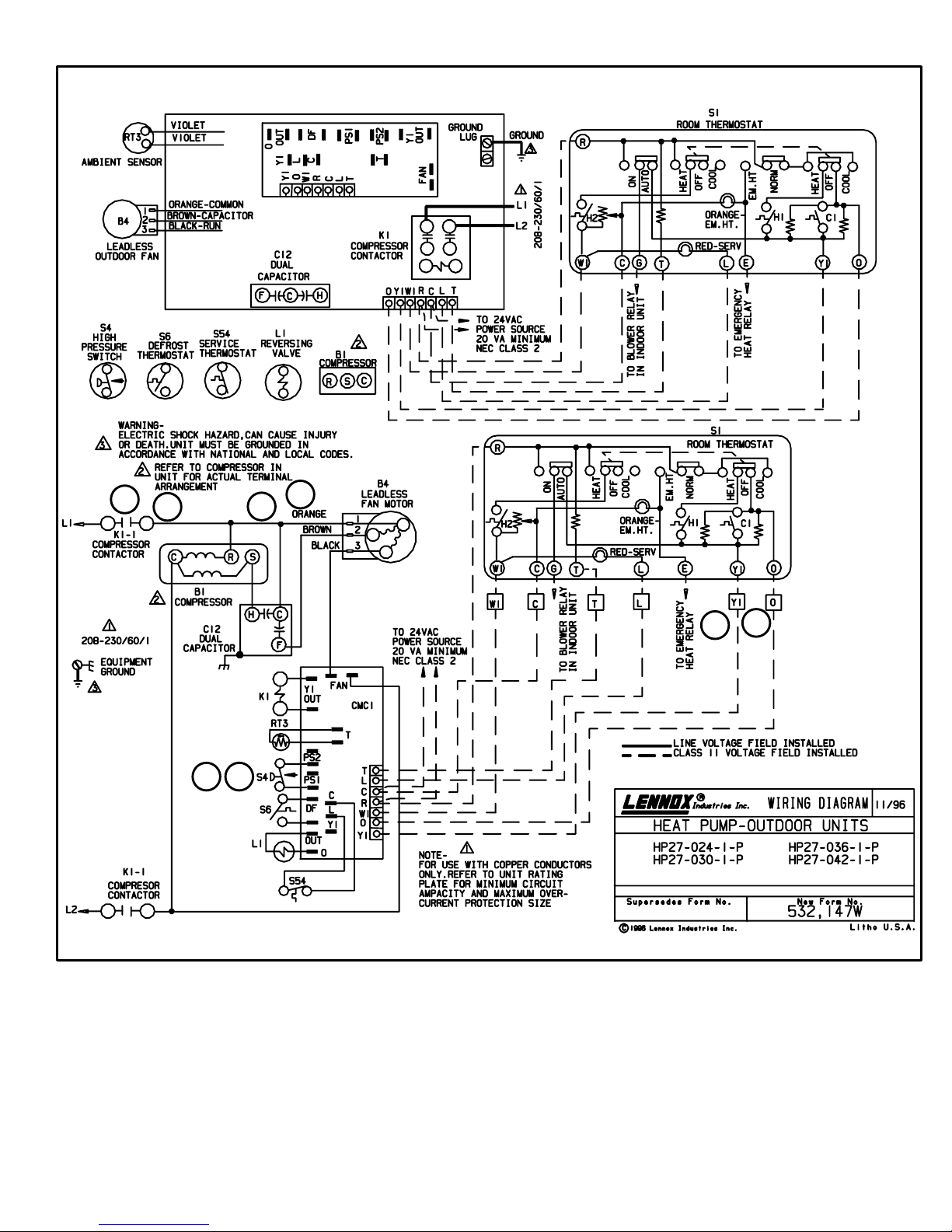
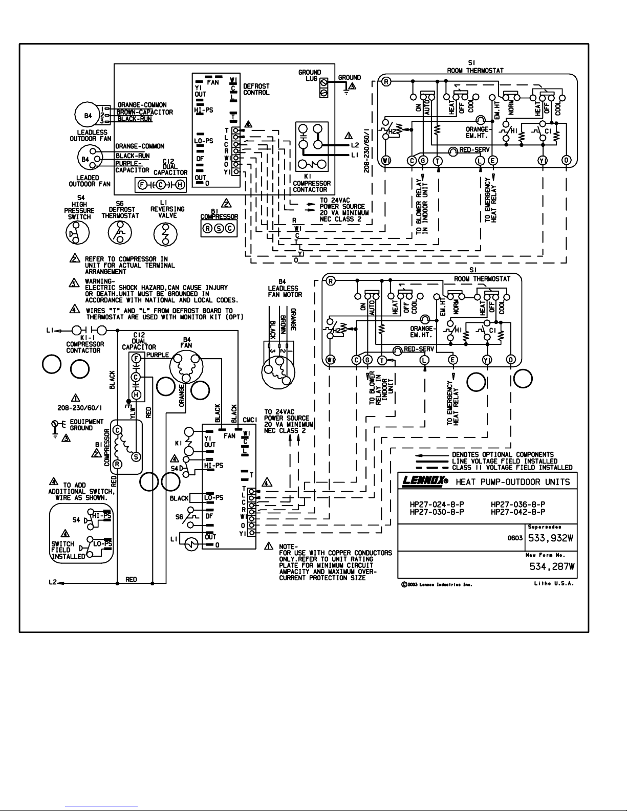
C−Diagram HP27−1−208/230 Volt
3
7
2
6
8
4
1
5
Page 19

D−Diagram HP27−6−208/230 Volt
8
4
3
7
1
5
2
6
Page 20

E−Diagram HP27−7−208/230 Volt
8
4
3
7
5
2
6
1
Page 21
F−Diagram HP27−7−208/230 Volt
3
7
8
6
4
2
5
1
Page 22

Operating Sequence HP27
NOTE− Transformer in indoor unit supplies power
(24VAC) to the thermostat and outdoor unit controls.
COOLING
1 − Internal wiring energizes terminal O by cooling mode
selection, energizing the reversing valve. Cooling demand initiates at Y1 in the thermostat.
2 − 24VAC energizes N.C. high pressure limit S4 which
energizes compressor contactor K1.
3 − K1−1 N.O. contacts close energizing compressor B1
and outdoor fan motor B4.
4 − Compressor B1 and outdoor fan motor B4 begin im-
mediate operation.
HEATING
5 − Internal thermostat wiring de−energizes terminal O by
heating mode selection, de−energizing the reversing
valve. Heating demand initiates at Y1.
6 − 24VAC energizes N.C. high pressure limit S4 and
compressor contactor K1.
7 − K1−1 N.O. contacts close energizing compressor and
outdoor fan motor.
8 − Compressor B1 and outdoor fan motor B4 begin im-
mediate operation.
DEFROST MODE
9− During heating operation when outdoor coil tempera-
ture drops below 35F (2C) or 42(5.5C) see de-
frost system description for specific unit dash number
defrost switch (thermostat) S6 closes.
10− Defrost control CMC1 begins timing. If defrost
ther−mostat (S6) remains closed at the end of the
30,60 or 90 minute period, defrost relay energizes
and defrost begins.
11 − During defrost CMC1 energizes the reversing valve
and W1 on the terminal strip (operating indoor unit on
the first stage heat mode), while de-energizing outdoor
fan motor B4.
12 − Defrost continues 14 + 1 minutes or until thermostat
switch (S6) opens. When defrost thermostat opens,
defrost control timer loses power and resets.
13 − When CMC1 resets, the reversing valve and W1 on
the terminal strip are de-energized, while the outdoor
fan motor B4 is energized.
14− After each thermostat demand, time delaylocks out
the circuit to compressor contactor coil and defrost
control for 5 minutes + 2 minutes. At the end of the
timed period, the time delay allows the compressor
contactor and defrost control to be energized upon demand as in step 1.
Page 23
 Loading...