

Page 1
504,712M
*P504712M*
06/04
*2P0604*
2002 Lennox Industries Inc.
Dallas, Texas, USA
®
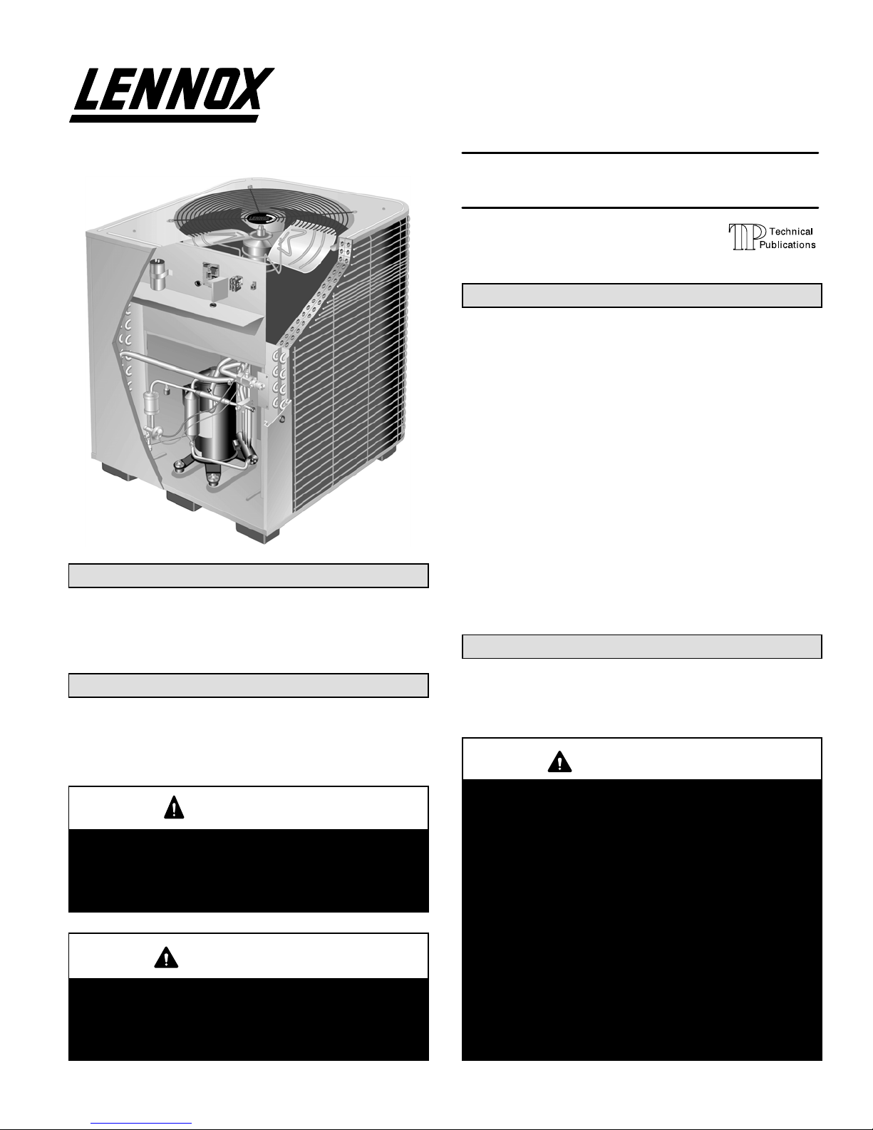
HP27 Outdoor Unit
HP27 outdoor units are designed for expansion valve systems only. They are not designed for RFC systems. Refer to
Lennox engineering handbook for expansion valve kits
which you must order separately.
Shipping & Packing List
1 − Assembled HP27 outdoor unit
2 − Grommets (for liquid and vapor lines)
Check equipment for shipping damage. If you find any
damage, immediately contact the last carrier.
WARNING
Improper installation, adjustment, alteration, service
or maintenance can cause property damage, personal injury or loss of life. Installation and service must
be performed by a qualified installer or service
agency.
IMPORTANT
The Clean Air Act of 1990 bans the intentional venting of refrigerant (CFC’s and HCFC’s) as of July 1,
1992. Approved methods of recovery, recycling or
reclaiming must be followed. Fines and/or incarceration may be levied for noncompliance.
INSTALLATION
INSTRUCTIONS
HP27 SERIES UNITS
HEAT PUMP UNITS
504,712M
06/04
Supersedes 12/03
Table of Contents
HP27 Outdoor Unit 1. . . . . . . . . . . . . . . . . . . . . . . . . . . . .
Shipping & Packing List 1. . . . . . . . . . . . . . . . . . . . . . . . .
General Information 1. . . . . . . . . . . . . . . . . . . . . . . . . . . .
Unit Dimensions 2. . . . . . . . . . . . . . . . . . . . . . . . . . . . . . .
Parts Arrangement 3. . . . . . . . . . . . . . . . . . . . . . . . . . . . .
Setting the Unit 3. . . . . . . . . . . . . . . . . . . . . . . . . . . . . . . .
Electrical 4. . . . . . . . . . . . . . . . . . . . . . . . . . . . . . . . . . . . . .
Refrigerant Piping 6. . . . . . . . . . . . . . . . . . . . . . . . . . . . . .
Refrigerant Metering Device 10. . . . . . . . . . . . . . . . . . . .
Service Valves 10. . . . . . . . . . . . . . . . . . . . . . . . . . . . . . . .
Leak Testing 11. . . . . . . . . . . . . . . . . . . . . . . . . . . . . . . . . .
Evacuation 12. . . . . . . . . . . . . . . . . . . . . . . . . . . . . . . . . . .
Start−Up 13. . . . . . . . . . . . . . . . . . . . . . . . . . . . . . . . . . . . . .
Manifold Gauge Set 13. . . . . . . . . . . . . . . . . . . . . . . . . . .
Charging 13. . . . . . . . . . . . . . . . . . . . . . . . . . . . . . . . . . . . .
System Operation 15. . . . . . . . . . . . . . . . . . . . . . . . . . . . .
Defrost System 16. . . . . . . . . . . . . . . . . . . . . . . . . . . . . . .
Maintenance 17. . . . . . . . . . . . . . . . . . . . . . . . . . . . . . . . . .
HP27 Check Points 18. . . . . . . . . . . . . . . . . . . . . . . . . . . .
RETAIN THESE INSTRUCTIONS
FOR FUTURE REFERENCE
General Information
These instructions are intended as a general guide and do
not supersede local codes in any way. Consult authorities
having jurisdiction before installation.
WARNING
This product and/or the indoor unit it is matched with
may contain fiberglass wool.
Disturbing the insulation during installation, maintenance, or repair will expose you to fiberglass wool
dust. Breathing this may cause lung cancer. (Fiberglass wool is known to the State of California to
cause cancer.)
Fiberglass wool may also cause respiratory, skin,
and eye irritation.
To reduce exposure to this substance or for further
information, consult material safety data sheets
available from address shown below, or contact your
supervisor.
Lennox Industries Inc.
P.O. Box 799900
Dallas, TX 75379−9900
Litho U.S.A.
Page 2
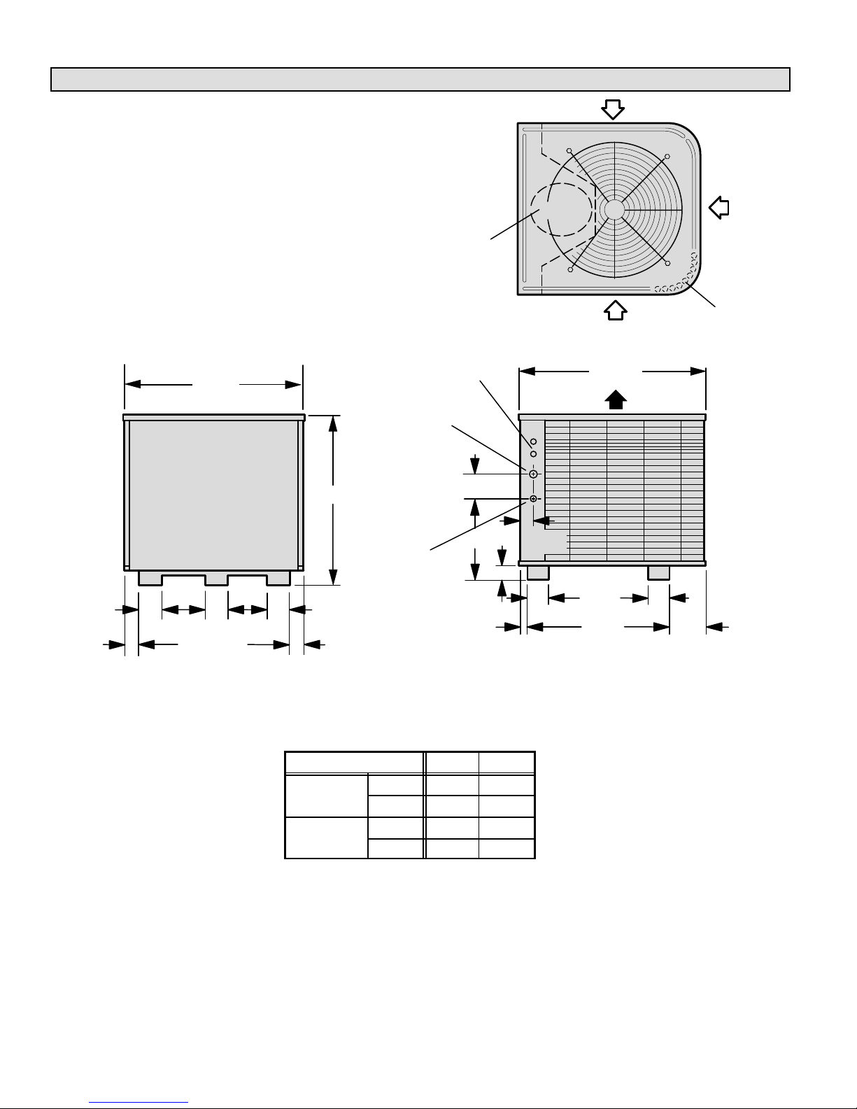
Unit Dimensions − inches (mm)
2-3/4
(70)
COMPRESSOR
INLET
INLET
AIR
TOP VIEW
SIDE VIEW
SERVICE ACCESS
ELECTRICAL
INLETS
VAP OR
LINE INLET
DISCHARGE
AIR
COIL DRAIN
OUTLETS
(Around perimeter
of base)
4
(102)
B
1-3/8
(35)
LIQUID
LINE INLET
4
(102)
6-1/16
(154)
AIR
INLET
AIR
A
4-7/8 (22)
4-1/2 (114)
2-9/16
(65)
2
(51)
2
(51)
13-5/8
(473)
26-5/8
(676)
7-1/2
(191)
7-1/2
(191)
3-7/8
(98)
3-7/8
(98)
28-1/8 (714)
32−1/8
(816)
34-1/16
(865)
Model No. A B
HS27-024
in. 40-7/8 19-13/16
HS27-024
HP27-030
mm 1038 503
HP27-036
in. 44-7/8 14-1/4
HP27-036
HP27-042
mm 1140 362
Page 3
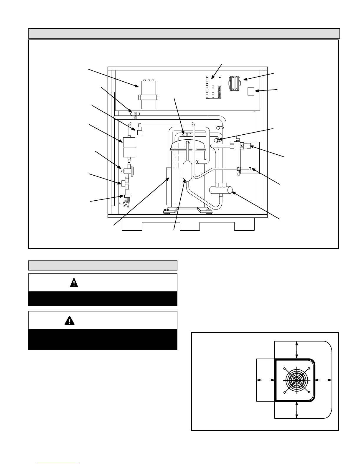
Parts Arrangement
Figure 1
HP27 UNIT COMPONENTS
CONTACTOR
DEFROST CONTROL/TIMED−OFF CONTROL
LIQUID LINE
SERVICE VALVE
AND GAUGE
PORT
VAPOR LINE
SERVICE VALVE
AND GAUGE
PORT
MUFFLER
EXPANSION VALVE
WITH
INTERNAL CHECK VALVE
REVERSING
VALV E
AND SOLENOID
BIFLOW
FILTER/DRIER
DUAL
CAPACITOR
DISTRIBUTOR
HIGH PRESSURE
SWITCH
GROUND LUG
DEFROST
THERMOSTAT
TXV
SENSING BULB −036,
−042 ONLY
VAPOR GAUGE
PORT
ACCUMULATOR
TXV
SENSING BULB
−024, −030 ONLY
Setting the Unit
CAUTION
In order to avoid injury, take proper precaution when
lifting heavy objects.
CAUTION
Danger of sharp metallic edges. Can cause injury.
Take care when servicing unit to avoid accidental
contact with sharp edges.
The outdoor units operate under a wide range of weather
conditions; therefore, several factors must be considered
when positioning the outdoor unit. The unit must be positioned to give adequate clearances for sufficient airflow
and servicing. A minimum clearance of 24inches (610 mm)
between multiple units must be maintained. Refer to figure
2 for installation clearances.
1 − Place a sound−absorbing material, such as Isomode,
under the unit if you intend to install it in a location or a
position that will transmit sound or vibration to the living area or adjacent buildings.
2 − Install the unit high enough above ground or roof to
prevent ice build−up and to allow adequate drainage of
defrost water.
3 − In areas that receive heavy snow, do not locate the unit
where drifting will occur. Ensure that the unit base is
elevated above the depth of average snows.
NOTE − Elevate the unit by constructing a frame using
suitable materials. If you construct a support frame, it
must not block drain holes in the base of the unit.
36"
(914 mm)
36"
(914 mm)
*36"
(914 mm)
*36"
(914 mm)
Installation Clearances
NOTE − A service access
clearance of 30" (762 mm)
must be maintained in front
of the service access panel.
Clearance to one side must
be 36" (914 mm). Clearance
to one of the remaining two
sides may be 12" (304 mm)
and the final side may be 6"
(152 mm).
NOTE − A clearance of 24" (610 mm)
must be maintained between two units.
NOTE − 48" (1219 mm) clearance required on top
of unit. Maximum soffit overhang is 36" (914 mm).
Figure 2

Page 4
4 − When you install the unit in areas where low ambient
temperatures exist, locate the unit so winter prevailing
winds do not blow directly into outdoor coil.
5 − Locate the unit away from overhanging roof lines
which would allow water or ice to drop on, or in front of,
the coil or into the unit.
Slab Mounting
When installing the unit at grade level, the top of the slab
should be high enough above the grade so that water from
higher ground will not collect around the unit. See figure 3.
The slab should have a slope tolerance away from the
building of 2 degrees or 2 inches per 5 feet (51 mm per 1.5
m). This will prevent ice from building up under the unit during a defrost cycle. Refer to the roof mounting section for
barrier construction if the unit must face prevailing winter
winds.
2 degrees or
2 in. per 5 foot
(51 mm per 1.5 m)
slope tolerance away
from building structure
Slab Mounting
ground level
mounting
slab
building
structure
discharge air
Figure 3
Roof Mounting
If you are unable to mount the unit coil away from prevailing
winter winds, construct a wind barrier. See figure 4. Size
the barrier at least the same height and width as the outdoor unit. Mount the barrier 24 inches (610 mm) from the
sides of the unit in the direction of prevailing winds.
WIND BARRIER
INLET AIR
PREVAILING WINTER WINDS
Rooftop Application
Wind Barrier Construction
INLET AIR
INLET
AIR
Figure 4
24 in.
(610 mm)
Electrical
In the U.S.A., wiring must conform with current local codes
and the current National Electric Code (NEC). In Canada,
wiring must conform with current local codes and the current
Canadian Electrical Code (CEC).
Refer to the furnace or blower coil installation instructions
for additional wiring application diagrams and refer to unit
nameplate for minimum circuit ampacity and maximum
overcurrent protection size.
Page 5
WARNING
Unit must be grounded in accordance with national
and local codes.
Electric Shock Hazard.
Can cause injury or death.
1 − Install line voltage power supply to unit from a properly
sized disconnect switch.
2 − Ground unit at unit disconnect switch or to an earth
ground.
NOTE − To facilitate conduit, a hole is in the bottom of
the control box. Connect conduit to the control box us
ing a proper conduit fitting.
NOTE − Units are approved for use only with copper
conductors.
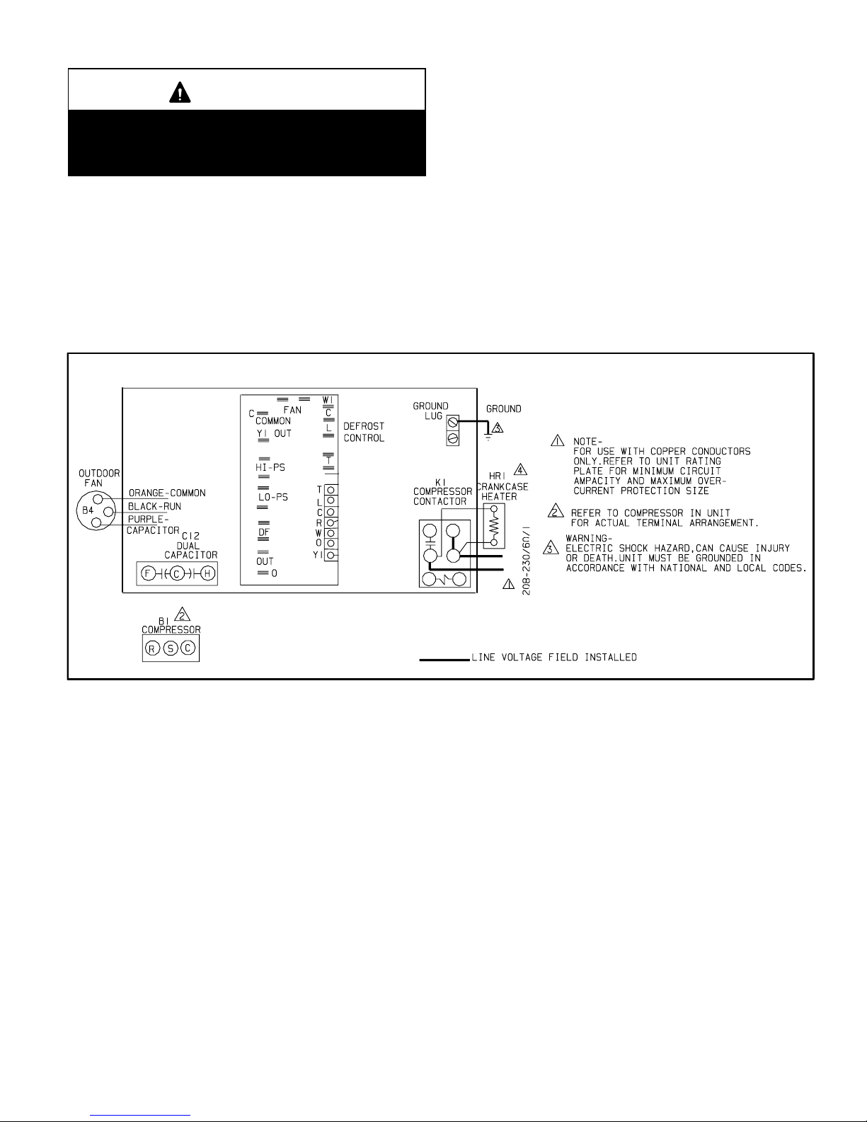
24V, Class II circuit connections are made in the low
voltage junction box. Refer to figure 5 for field wiring
diagram.
NOTE − A complete unit wiring diagram is located in
side the unit control box cover.
3 − Install room thermostat (ordered separately) on an in-
side wall approximately in the center of the conditioned
area and 5 feet (1.5 m) from the floor. It should not be
installed on an outside wall or where it can be effected
by sunlight, drafts or vibrations.
4 − Install voltage wiring from outdoor to indoor unit and
from thermostat to indoor unit. See figures 6 and 7.
Typical Field Wiring Diagram
Figure 5
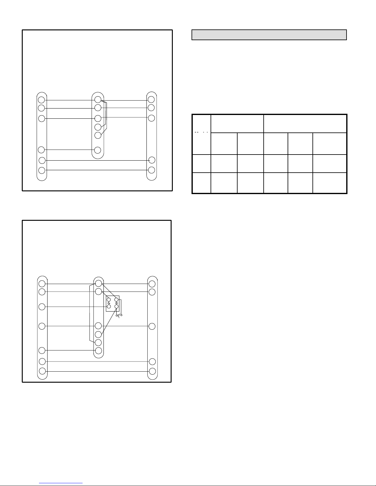
Page 6
R
C
W1
Y1
O
G
R
C
W1
W2
W3
G
reversing valve
Outdoor Unit and Blower Unit
Thermostat Designations
(Some connections may not apply.
Refer to specific thermostat and indoor unit.)
Thermostat
Indoor
Unit
R
C
W1
Y1
O
Outdoor
Unit
power
power
common common
1st. stage aux. heat
1st. stage aux. heat
indoor blower
compressor
Figure 6
R
C
W1
Y1
O
G
R
C
W1
W2
W3
G
Outdoor Unit and Blower Unit
Thermostat Designations
(with auxiliary heat)
(Some connections may not apply.
Refer to specific thermostat and indoor unit.)
Thermostat
Indoor
Unit
Outdoor
Unit
E
R
C
W1
Y1
O
reversing valve
indoor blower
compressor
power
power
common common
1st. stage aux. heat
1st. stage aux. heat
emergency heat
Figure 7
Refrigerant Piping
Field refrigerant piping consists of liquid and vapor lines
from the outdoor unit (sweat connections) to the indoor coil
(flare or sweat connections). Use Lennox L15 (sweat, nonflare) series line sets as shown in table 1 or use field-fabricated refrigerant lines. Refer to Refrigerant Piping Guide
(Corp. 9351−L9) for proper size, type, and application of
field−fabricated lines. Valve sizes are also listed in table 1.
Table 1
Refrigerant Line Set
s
Valve Field Size
Connections
Recommended Line Set
Model
Liquid
Line
Vapor
Line
Liquid
Line
Vapor
Line
L15
Line Sets
−024
−030
3/8 in.
9.5 mm
3/4 in.
19.1 mm
3/8 in.
9.5 mm
3/4 in.
19.1 mm
L15−41
15 ft.−50 ft.
4.6 m−15.2 m
−036
−042
3/8 in.
9.5 mm
7/8 in.
22.2 mm
3/8 in.
9.5 mm
7/8 in.
22.2 mm
L15−41
15 ft.−50 ft.
4.6 m−15.2 m
Installing Refrigerant Line
During the installation of any heat pump or a/c system, it is
important to properly isolate the refrigerant lines to prevent
unnecessary vibration. Line set contact with the structure
(wall, ceiling or floor) causes some objectionable noise
when vibration is translated into sound. As a result, more
energy or vibration can be expected. Closer attention to
line set isolation must be observed.
Following are some points to consider when placing and
installing a high−efficiency outdoor unit:
1- Placement − Be aware some localities are adopting
sound ordinances based on how noisy the unit is from
the adjacent property not at the original installation.
Install the unit as far as possible from the property line.
When possible, do not install the unit directly outside a
window. Glass has a very high level of sound transmission.
2- Line Set Isolation − The following illustrations demon-
strate procedures which ensure proper refrigerant line
set isolation. Figure 8 shows how to install line sets on
vertical runs. Figure 9 shows how to install line sets on
horizontal runs. Figure 10 shows how to make a transition from horizontal to vertical. Finally, figure 11 shows
how to place the outdoor unit and line set.
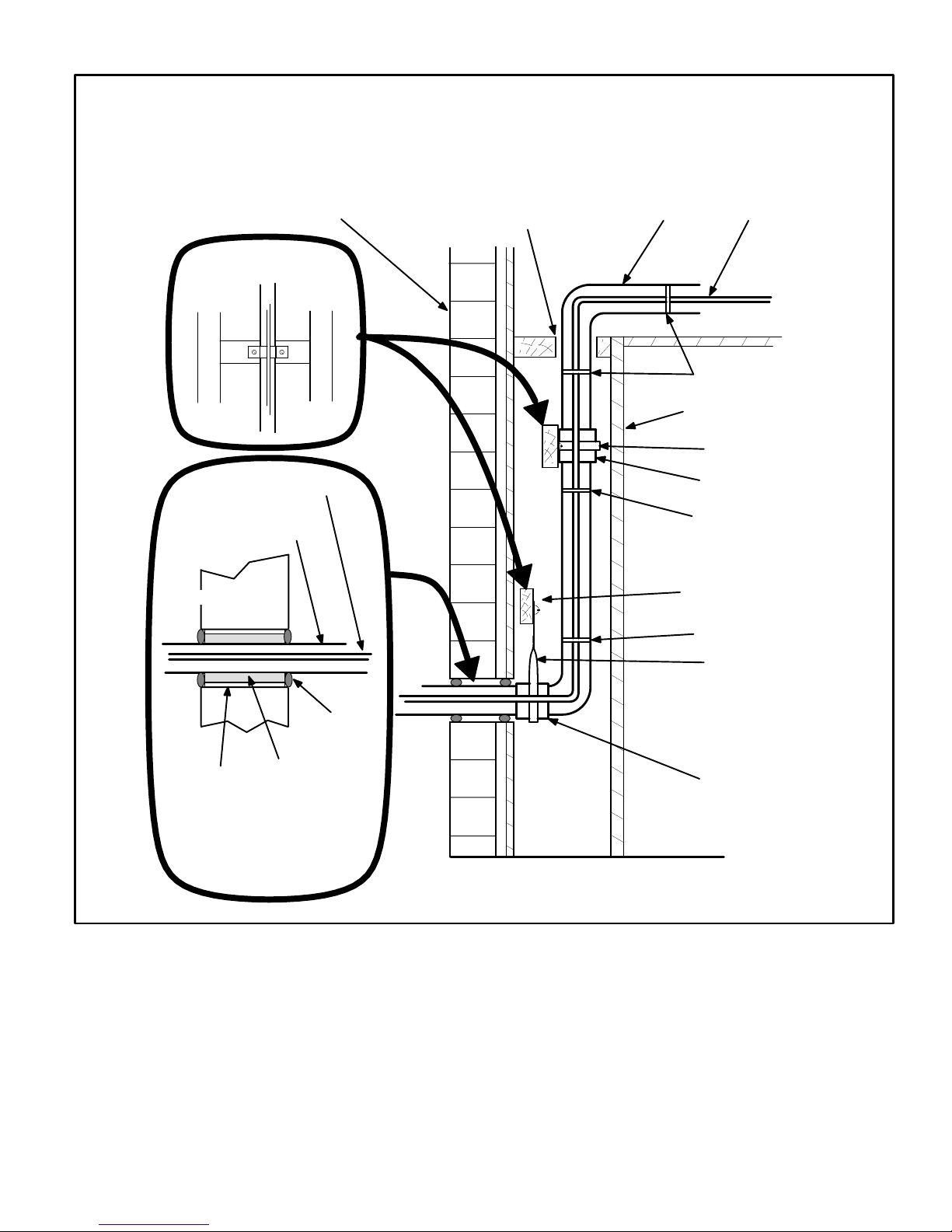
Page 7
Refrigerant Line Sets
How To Install Vertical Runs
(new construction shown)
PVC Pipe
Fiberglass
Insulation
Caulk
Outside Wall
Vapor Line
(wrapped with Armaflex)
Liquid Line
IMPORTANT - Refrigerant
lines must not contact
structure.
Outside Wall
Inside Wall
Liquid LineVapor Line
IMPORTANT - Refrigerant
lines must not contact wall.
Wood Block
Between Studs
Strap
Sleeve
Wood Block
Strap
Sleeve
Wire Tie
Wire Tie
Wire Tie
NOTE - Similar installation practices should be used if
line set is to be installed on exterior of outside wall.
Figure 8

Page 8
Refrigerant Line Sets:
Installing Horizontal Runs
8 feet
8 feet
Metal Sleeve
Strapping Material (around vapor line only)
Tape or Wire Tie
Wire Tie
(around vapor line only)
Floor Joist or
Roof Rafter
Tape or Wire Tie
Strap the vapor line to the joist or rafter at 8 ft.
intervals then strap the liquid line to the vapor line.
To hang line set from joist or rafter,
use either metal strapping material
or anchored heavy nylon wire ties.
Floor Joist or Roof Rafter
Figure 9

Page 9
Refrigerant Line Sets:
Transition From Vertical To Horizontal
Liquid Line
Vapor Line
Wrapped in
Armaflex
Strap Liquid Line
To Vapor Line
Metal
Sleeve
Anchored Heavy
Nylon Wire Tie
Automotive
Muffler-Type
Hanger
Wall
Stud
Wall
Stud
Liquid Line
Vapor Line
Wrapped in
Armaflex
Strap Liquid Line
To Vapor Line
Metal
Sleeve
Figure 10
Outside Unit Placement and Installation
Install unit away from windows.
Two 90° elbows
installed in line set
will reduce line set
vibration.
Figure 11

Page 10
Isolation Grommets
Locate the provided isolation grommets. Use a knife to slit
the webbing on each grommet. Slide larger grommet onto
vapor line and smaller grommet onto liquid line. Insert
grommets into mullion to isolate refrigerant lines from
sheet metal edges.
Brazing Connection Procedure
1 − Cut ends of the refrigerant lines square (free from nicks
or dents). Debur the ends. The pipe must remain
round, do not pinch end of the line.
2 − Before making line set connections, use dry nitrogen to
purge the refrigerant piping. This will help to prevent
oxidation and the introduction of moisture into the system.
3 − Use silver alloy brazing rods (5 or 6 percent minimum
silver alloy for copper−to−copper brazing or 45 percent
silver alloy for copper−to−brass or copper−to−steel brazing) which are rated for use with HCFC22 refrigerant.
Wrap a wet cloth around the valve body and the copper
tube stub. Braze the line set to the service valve.
4 − Wrap a wet cloth around the valve body and copper
tube stub to protect it from heat damage during brazing. Wrap another wet cloth underneath the valve body
to protect the base paint.
NOTE − The tube end must stay bottomed in the fitting
during final assembly to ensure proper seating, sealing
and rigidity.
5 − Install a field−provided thermal expansion valve (ap-
proved for use with HCFC22 refrigerant) in the liquid
line at the indoor coil.
Refrigerant Metering Device
HP27 units are used in check expansion valve systems
only. See the Lennox Engineering Handbook for approved
TXV match-ups and application information.
Check expansion valves equipped with Chatleff fittings
are available from Lennox. Refer to the Engineering
Handbook for applicable expansion valves for use with
specific match-ups.
If you install a check expansion valve with an indoor coil
that includes a fixed orifice, remove the orifice before
installing the check expansion valve.
IMPORTANT
Failure to remove RFC orifice when installing an expansion valve on the indoor coil will result in improper operation and damage to the system.
See figure 12 for installation of the check expansion valve.
Metering Device Installation
expansion
valve
o−ring
o−ring
strainer
liquid line
stub
distributor
Figure 12
Service Valves
Access the liquid line and vapor line service valves (figures
13 and 14) and gauge ports are used for leak testing, evacuating, charging and checking charge. See table 2 for
torque requirements.
Each valve is equipped with a service port which has a factory−installed Schrader valve. A service port cap protects
the Schrader valve from contamination and serves as the
primary leak seal.
Table 2
Torque Requirements
Part Recommended Torque
Service valve cap 8 ft.− lb. 11 NM
Sheet metal screws 16 in.− lb. 2 NM
Machine screws #10 28 in.− lb. 3 NM
Compressor bolts 90 in.− lb. 10 NM
Gauge port seal cap 8 ft.− lb. 11 NM
IMPORTANT
Service valves are closed to the outdoor unit and
open to line set connections. Do not open the valves
until refrigerant lines have been leak tested and
evacuated. All precautions should be exercised to
keep the system free from dirt, moisture and air.
To Access Schrader Port:
1 − Remove the service port cap with an adjustable wrench.
2 − Connect the gauge to the service port.
3 − When testing is complete, replace the service port cap.
Tighten finger tight, then an additional 1/6 turn.
To Open Service Valve:
1 − Remove the stem cap with an adjustable wrench.
2 − Use a service wrench with a hex head extension to back
the stem out counterclockwise as far as it will go.
NOTE − Use a 3/16" hex head extension for liquid line
sizes or a 5/16" extension for vapor line sizes.

Page 11
3 − Replace the stem cap. Tighten finger tight, then tighten
an additional 1/6 turn.
To Close Service Valve:
1 − Remove the stem cap with an adjustable wrench.
2 − Use a service wrench with a hex head extension to turn
the stem clockwise to seat the valve. Tighten firmly.
NOTE − Use a 3/16" hex head extension for liquid line
sizes or a 5/16" extension for vapor line sizes.
3 − Replace the stem cap. Tighten finger tight, then tighten
an additional 1/6 turn.
Liquid Line Service Valve
(Valve Open)
Schrader
valve
service
port
service port
cap
insert hex
wrench here
to indoor coil
to outdoor coil
stem cap
Schrader valve open
to line set when valve is
closed (front seated)
service
port
service
port cap
stem cap
insert hex
wrench here
Liquid Line Service Valve
(Valve Closed)
(valve front seated)
to outdoor coil
to indoor coil
Figure 13
Ball−Type Vapor Line Service Valve
Vapor line service valves function the same way as the other valves, the difference is in the construction. These
valves are not rebuildable. If a valve has failed, you must
replace it. A ball valve valve is illustrated in figure 14.
The ball valve is equipped with a service port with a factory−
installed Schrader valve. A service port cap protects the
Schrader valve from contamination and assures a leak−
free seal.
Vapor Line Service Valve
(Valve Open)
Schrader
valve
stem cap
To open: rotate stem counter-clockwise 90.
To close: use adjustable wrench and
rotate stem clockwise 90.
ball
(shown open)
service port
cap
service
port
field side
unit side
stem
Figure 14
Leak Testing
After the line set has been connected to the indoor and
outdoor units, check the line set connections and indoor
unit for leaks.
WARNING
Danger of fire. Bleeding the refrigerant
charge from only the high side may
result in the low side shell and suction tubing being pressurized. Appplication of a brazing torch while pressurized may result in ignition of the
refrigerant and oil mixture − check the
high and low pressures before unbrazing.
WARNING
Refrigerant can be harmful if it is inhaled. Refrigerant
must be used and recovered responsibly.
Failure to follow this warning may result in personal
injury or death.
WARNING
Danger of explosion: Can cause
equipment damage, injury or death.
Never use oxygen to pressurize a refrigeration or air conditioning system.
Oxygen will explode on contact with
oil and could cause personal injury.

Page 12
WARNING
Danger of explosion: Can cause equipment damage,
injury or death. When using a high pressure gas
such as dry nitrogen to pressurize a refrigeration or
air conditioning system, use a regulator that can
control the pressure down to 1 or 2 psig (6.9 to 13.8
kPa).
Using an Electronic Leak Detector or Halide
1 − Connect a cylinder of HCFC-22 to the center port of the
manifold gauge set.
2 − With both manifold valves closed, open the valve on
the HCFC-22 cylinder (vapor only).
3 − Open the high pressure side of the manifold to allow
the HCFC-22 into the line set and indoor unit. Weigh in
a trace amount of HCFC-22. [A trace amount is a maxi-
mum of 2 ounces (57 g) or 3 pounds (31 kPa) pressure.] Close the valve on the HCFC-22 cylinder and the
valve on the high pressure side of the manifold gauge
set. Disconnect the HCFC-22 cylinder.
4 − Connect a cylinder of nitrogen with a pressure regulat-
ing valve to the center port of the manifold gauge set.
5 − Connect the manifold gauge set high pressure hose to
the vapor valve service port. (Normally, the high pres-
sure hose is connected to the liquid line port; however,
connecting it to the vapor port better protects the manifold gauge set from high pressure damage.)
6 − Adjust the nitrogen pressure to 150 psig (1034 kPa).
Open the valve on the high side of the manifold gauge
set which will pressurize line set and indoor unit.
7 − After a few minutes, open a refrigerant port to ensure
the refrigerant you added is adequate to be detected.
(Amounts of refrigerant will vary with line lengths.)
Check all joints for leaks. Purge nitrogen and HCFC-22
mixture. Correct any leaks and recheck.
Evacuation
Evacuating the system of noncondensables is critical for
proper operation of the unit. Noncondensables are defined
as any gas that will not condense under temperatures and
pressures present during operation of an air conditioning
system. Noncondensables and water vapor combine with
refrigerant to produce substances that corrode copper piping and compressor parts.
IMPORTANT
Use a thermocouple or thermistor electronic vacuum
gauge that is calibrated in microns. Use an instrument
that reads from 50 microns to at least 10,000 microns.
1 − Connect manifold gauge set to the service valve ports
as follows:
low pressure gauge to vapor service port
high pressure gauge to liquid line service valve
2 − Connect micron gauge.
3 − Connect the vacuum pump (with vacuum gauge) to the
center port of the manifold gauge set.
4 − Open both manifold valves and start the vacuum pump.
5 − Evacuate the line set and indoor unit to an absolute
pressure of 23,000 microns (29.01 inches of mercury). During the early stages of evacuation, it is desirable to close the manifold gauge valve at least once to
determine if there is a rapid rise in absolute pressure.
A rapid rise in pressure indicates a relatively large leak.
If this occurs, repeat the leak testing procedure.
NOTE − The term absolute pressure means the total
actual pressure within a given volume or system,
above the absolute zero of pressure. Absolute pressure in a vacuum is equal to atmospheric pressure minus vacuum pressure.
6 − When the absolute pressure reaches 23,000 microns
(29.01 inches of mercury), close the manifold gauge
valves, turn off the vacuum pump and disconnect the
manifold gauge center port hose from vacuum pump.
Attach the manifold center port hose to a nitrogen cylinder with pressure regulator set to 150 psig (1034 kPa)
and purge the hose. Open the manifold gauge valves
to break the vacuum in the line set and indoor unit.
Close the manifold gauge valves.
CAUTION
Danger of Equipment Damage.
Avoid deep vacuum operation. Do not use compressors to evacuate a system.
Extremely low vacuums can cause internal arcing
and compressor failure.
Damage caused by deep vacuum operation will void
warranty.
7 − Shut off the nitrogen cylinder and remove the manifold
gauge hose from the cylinder. Open the manifold
gauge valves to release the nitrogen from the line set
and indoor unit.
8 − Reconnect the manifold gauge to the vacuum pump,
turn the pump on, and continue to evacuate the line set
and indoor unit until the absolute pressure does not
rise above 500 microns (29.9 inches of mercury) within
a 20−minute period after shutting off the vacuum pump
and closing the manifold gauge valves.
9 − When the absolute pressure requirement above has
been met, disconnect the manifold hose from the vacuum pump and connect it to an upright cylinder of
HCFC-22 refrigerant. Open the manifold gauge valves
to break the vacuum from 1 to 2 psig positive pressure in
the line set and indoor unit. Close manifold gauge
valves and shut off the HCFC-22 cylinder and remove
the manifold gauge set.

Page 13
Start−Up
Cooling Start−Up
IMPORTANT
If unit is equipped with crankcase heater, it should be
energized 24 hours before unit start−up to prevent
compressor damage as a result of slugging.
1 − Rotate fan to check for frozen bearings or binding.
2 − Inspect all factory− and field-installed wiring for loose
connections.
3 − After evacuation is complete, open the liquid line and
vapor line service valves (counterclockwise) to release
refrigerant charge (contained in outdoor unit) into the
system.
4 − Replace stem caps and secure finger tight, then tight-
en an additional (1/6) one-sixth of a turn.
5 − Check voltage supply at the disconnect switch. The
voltage must be within the range listed on the unit
nameplate. If not, do not start the equipment until the
power company has been consulted and the voltage
condition has been corrected.
6 − Set the thermostat for a cooling demand, turn on power
to indoor blower unit and close the outdoor unit disconnect to start the unit.
7 − Recheck voltage while the unit is running. Power must
be within range shown on the nameplate.
Manifold Gauge Set
When checking the unit charge, use a manifold gauge set
equipped with low loss" hoses. Do not use a manifold
gauge set that has anything other than a low loss" hose.
Charging
The unit is factory−charged with the amount of HCFC−22 refrigerant that is indicated on the unit rating plate. This
charge is based on a matching indoor coil and outdoor coil
with a 15 foot (4.6 m) line set. For varying lengths of line set,
refer to table 3 for refrigerant charge adjustment.
Table 3
Liquid Line
Set Diameter
Oz. per 5 ft. (g per 1.5 m) adjust
from 15 ft. (4.6 m) line set*
3/8 in.
(9.5 mm)
3 ounces per 5 ft. (88.05 g per 1.5 m)
*If line set length is greater than 15 ft. (4.6 m), add this amount. If line set
length is less than 15 ft. (4.6 m), subtract this amount.
The outdoor unit should be charged during warm weather.
However, applications arise in which charging must occur
in the colder months. The method of charging is deter-
mined by the unit’s refrigerant metering device and the outdoor ambient temperature.
Measure the liquid line temperature and the outdoor ambient temperature as outlined below:
1 − Close manifold gauge set valves. Connect manifold
gauge set to service valves as shown in figure 16.
low pressure gauge to vapor valve service port
high pressure gauge to liquid valve service port
Connect the center manifold hose to an upright cylinder of HCFC−22.
2 − Set the room thermostat to call for heat. This will create
the necessary load for properly charging the system in
the cooling cycle.
3 − Use a digital thermometer to record the outdoor ambi-
ent temperature.
4 − When the heating demand has been satisfied, switch
the thermostat to cooling mode with a set point of 68F
(20C). When pressures have stabilized, use a digital
thermometer to record the liquid line temperature.
5 − The outdoor temperature will determine which charg-
ing method to use. Proceed with the appropriate charging procedure.
Weighing in the Charge TXV Systems –
Outdoor Temp < 65F (18C)
If the system is void of refrigerant, or if the outdoor ambient
temperature is cool, the refrigerant charge should be
weighed into the unit. Do this after any leaks have been repaired.
1 − Recover the refrigerant from the unit.
2 − Conduct a leak check, then evacuate as previously
outlined.
3 − Weigh in the unit nameplate charge.
If weighing facilities are not available or if you are charging
the unit during warm weather, follow one of the other procedures outlined below.
Subcooling Method
Outdoor Temp. < 65°F (18°C)
When the outdoor ambient temperature is below 65°F
(18°C), use the subcooling method to charge the unit. It
may be necessary to restrict the air flow through the outdoor coil to achieve pressures in the 200−250 psig
(1379−1724 kPa) range. These higher pressures are nec-
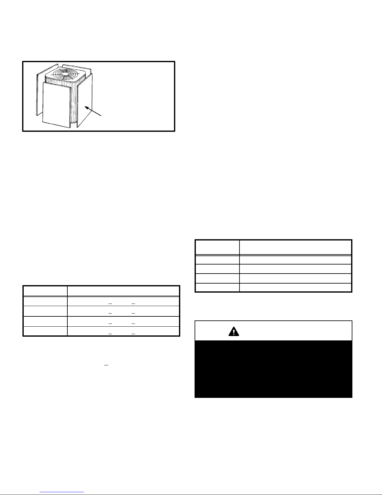
Page 14
essary for checking the charge. Block equal sections of air
intake panels and move obstructions sideways until the liquid pressure is in the 200−250 psig (1379−1724 kPa) range.
See figure 15.
Blocking Outdoor Coil
cardboard or
plastic sheet
Outdoor coil should be
blocked one side
at a time with cardboard
or plastic sheet until proper
testing pressures
are reached.
Figure 15
1 − With the manifold gauge hose still on the liquid service
port and the unit operating stably, use a digital ther-
mometer to record the liquid line temperature.
2 − At the same time, record the liquid line pressure reading.
3 − Use a temperature/pressure chart for HCFC-22 to de-
termine the saturation temperature for the liquid line
pressure reading.
4 − Subtract the liquid line temperature from the saturation
temperature (according to the chart) to determine sub-
cooling. (Saturation temperature − Liquid line tem-
perature = Subcooling)
5 − Compare the subcooling value with those in table 4. If
subcooling is greater than shown, recover some refrig-
erant. If subcooling is less than shown, add some re-
frigerant.
Table 4
Subcooling Values
Model Subcooling _F (_C)
HP27−024 8 + 2 (4.4 + 1)
HP27−030 7 + 2 (3.9 + 1)
HP27−036 8 + 2 (4.4 + 1)
HP27−042 7 + 2 (3.9 + 1)
Charging Using Normal Operating Pressures
and the Approach Method
Outdoor Temp. >
65F (18C)
The following procedure is intended as a general guide and
is for use on expansion valve systems only. For best results,
indoor temperature should be 70°F (21°C) to 80°F (26°C).
Monitor system pressures while charging.
1 − Record outdoor ambient temperature using a digital
thermometer.
2 − Attach high pressure gauge set and operate unit for
several minutes to allow system pressures to stabilize.
3 − Compare stabilized pressures with those provided in
table 6, Normal Operating Pressures." Minor variations in these pressures may be expected due to differences in installations. Significant differences could
mean that the system is not properly charged or that a
problem exists with some component in the system.
Pressures higher than those listed indicate that the
system is overcharged. Pressures lower than those
listed indicate that the system is undercharged. Verify
adjusted charge using the approach method.
Approach Method
4 − Use the same digital thermometer used to check out-
door ambient temperature to check liquid line temperature. Verify the unit charge using the approach method.
5 − The difference between the ambient and liquid temper-
atures should match values given in table 5. If the values don’t agree with the those in table 5, add refrigerant to lower the approach temperature or recover
refrigerant from the system to increase the approach
temperature.
Table 5
Approach Values
Model
Liquid Temp. Minus Ambient
Temp. _F (_C)
HP27−024 8 + 1 (4.4 + .5)
HP27−030 5 + 1 (2.8 + .5)
HP27−036 5 + 1 (2.8 + .5)
HP27−042 8 + 1 (4.4 + .5)
IMPORTANT
Use table 6 as a general guide when performing
maintenance checks. This is not a procedure for
charging the unit (Refer to Charging/Checking
Charge section). Minor variations in these pressures
may be expected due to differences in installations.
Significant differences could mean that the system
is not properly charged or that a problem exists with
some component in the system.

Page 15
Table 6
Normal Operating Pressures
Outdoor Coil
HP27-024 HP27-030 HP27−036 HP27-042
Mode
Outdoor Coil
Air Entering
Temperature F
liq. +
10 psig
vapor +
5 psig.
liq. +
10 psig
vapor +
5 psig.
liq. +
10 psig
vapor+
5 psig.
liq. +
10 psig
vapor +
5 psig.
65 134 82 136 80 137 80 134 75
75 159 83 161 81 163 81 167 76
Cooli
ng
(TXV
85 186 84 188 82 190 82 199 77
(TXV
Only)
95 216 83 217 83 222 83 232 78
105 248 86 251 85 257 85 257 80
20 179 36 173 36 177 33 184 29
30 188 49 192 49 195 40 194 39
Heating
40 203 58 205 58 208 47 205 48
50 228 65 218 65 217 58 216 58
HP27 Cooling Cycle
(Showing Gauge Manifold Connections)
Figure 16
NOTE−Use gauge ports on vapor line valve and liquid valve for evacuating refrigerant lines
and indoor coil. Use vapor gauge port to measure vapor pressure during charging.
OUTDOOR COIL
DEFROST
THERMOSTAT
EXPANSION/CHECK VALVE
BIFLOW
FILTER/DRIER
LOW
PRESSURE
COMPRESSOR
REVERSING
VALV E
MUFFLER
NOTE − ARROWS INDICATE
DIRECTION OF REFRIGERANT FLOW
EXPANSION/CHECK
VALV E
INDOOR UNIT
OUTDOOR UNIT
LIQUID LINE
SERVICE PORT
GAUGE
MANIFOLD
DISTRIBUTOR
INDOOR
COIL
HIGH
PRESSURE
VAPOR
LINE
VALV E
VAPOR
SERVICE
PORT
TO
HCFC-22
DRUM
HIGH PRESSURE
LIMIT
THERMOMETER
WELL
ACCUMULATOR
System Operation
The outdoor unit and indoor blower cycle on demand from
the room thermostat. When the thermostat blower switch is
in the ON position, the indoor blower operates continuously.
CAUTION
Danger of Equipment Damage.
Do not bypass the discharge thermostat.
Filter Drier
The drier is equipped with an internal check valve for correct
refrigerant flow (Refer to figure 16). If replacement is necessary, order another of the same design and capacity. A liquid
line strainer gives additional compressor protection.
Emergency Heat (Amber Light)
An emergency heat function is designed into some room thermostats. This feature is applicable when isolation of the outdoor unit is required, or when auxiliary electric heat is staged
by outdoor thermostats. When the room thermostat is placed
in the emergency heat position, the outdoor unit control circuit
is isolated from power and field-provided relays bypass the
outdoor thermostats. An amber indicating light simultaneously
comes on to remind the homeowner that he is operating in the
emergency heat mode.
Emergency heat is usually used during an outdoor unit
shutdown, but it should also be used following a power outage if power has been off for over an hour and the outdoor
temperature is below 50°F (10°C). System should be left in
the emergency heat mode at least six hours to allow the
crankcase heater sufficient time to prevent compressor
slugging.
Page 16
High Pressure Switch
The HP27 is equipped with an auto-reset high pressure
switch (single-pole, single-throw) which is located on the
liquid line. The switch shuts off the compressor if the discharge pressure rises above the factory setting. The switch
is normally closed and is permanently adjusted to trip
(open) at 410 +
10 psig (2827 + 69 kPa). The switch resets
(closes) when the pressure drops below 210 +
20 psig
(1448 +
138 kPa).
Defrost System
The defrost system includes two components:
a defrost thermostat
a defrost control
Defrost Thermostat
The defrost thermostat is located on the liquid line between the check/expansion valve and the distributor.
When the defrost thermostat senses 42°F (5.5°C) or cooler, its contacts close and send a signal to the defrost control board to start the defrost timing. It also terminates defrost when the liquid line warms up to 70°F (21°C).
Defrost Control
The defrost control board includes the combined functions of a time/temperature defrost control, defrost
relay, time delay, diagnostic LEDs, and a terminal strip
for field wiring connections. See figure 17.
The control provides automatic switching from normal
heating operation to defrost mode and back. During compressor cycle (call for defrost), the control accumulates
compressor run times at 30, 60, or 90 minute field adjustable intervals. If the defrost thermostat is closed when the
selected compressor run time interval ends, the defrost
relay is energized and defrost begins.
Defrost Control Timing Pins
Each timing pin selection provides a different accumulated compressor run time period during one thermostat
run cycle. This time period must occur before a defrost
cycle is initiated. The defrost interval can be adjusted to
30 (T1), 60 (T2), or 90 (T3) minutes. See figure 17. The
defrost timing jumper is factory−installed to provide a
90−minute defrost interval. If the timing selector jumper is
not in place, the control defaults to a 90−minute defrost
interval. The maximum defrost period is 14 minutes and
cannot be adjusted.
A TEST option is provided for troubleshooting. The TEST
mode may be started any time the unit is in the heating
mode and the defrost thermostat is closed or jumpered. If the jumper is in the TEST position at power-up, the
control will ignore the test pins. When the jumper is placed
across the TEST pins for two seconds, the control will enter
the defrost mode. If the jumper is removed before an additional 5−second period has elapsed (7 seconds total), the
unit will remain in defrost mode until the defrost thermostat
opens or 14 minutes have passed. If the jumper is not removed until after the additional 5−second period has
elapsed, the defrost will terminate and the test option will
not function again until the jumper is removed and re−applied.
Time Delay
The timed−off delay is five minutes long. The delay helps
protect the compressor from short−cycling in case the power
to the unit is interrupted or a pressure switch opens. The
delay is bypassed by placing the timer select jumper across
the TEST pins for 0.5 seconds.
Pressure Switch Circuits
The defrost control includes two pressure switch circuits.
The high pressure switch (S4) is factory−connected to the
board’s HI PS terminals. The board also includes LO PS terminals to accommodate the addition of a field−provided low
pressure or loss of charge pressure switch. See figure 17.
This feature is available on all units.
During a single demand cycle, the defrost control will lock
out the unit after the third time that the circuit is interrupted
by any pressure switch that is wired to the control board. In
addition, the diagnostic LEDs will indicate a locked out
pressure switch after the third occurrence of an open pressure switch. See table 7. The unit will remain locked out until power is broken then remade to the control or until the
jumper is applied to the TEST pins for 0.5 seconds.
NOTE − The defrost control board ignores input from the
low pressure switch terminals during the TEST mode, during the defrost cycle, during the 90−second start−up period,
and for the first 90 seconds each time the reversing valve
switches heat/cool modes. If the TEST pins are jumpered
and the 5−minute delay is being bypassed, the LO PS
terminal signal is not ignored during the 90−second
start−up period.
Ambient Thermistor & Service Light Connection
The defrost control board provides terminal connections
for the ambient thermistor and a service light. The thermistor compensates for changes in ambient temperature
which might cause thermostat droop. The service light
thermostat provides a signal which activates the room thermostat service light during periods of inefficient operation.
Diagnostic LEDs
The defrost board uses two LEDs for diagnostics. The
LEDs flash a specific sequence according to the diagnosis.

Page 17
Defrost Control Board
FIGURE 17
24V
TERMINAL
STRIP
HIGH PRESSURE
SWITCH
TERMINALS
S4
S5
PRESSURE SWITCH
WIRING CONNECTIONS
High
Pressure
Switch
(Factory−wired)
OPTIONAL
PRESSURE
SWITCH
TERMINALS
(Remove factory−
installed jumper
to install
pressure switch.)
Optional
Pressure
Switch
(Field−provided
and installed −−
jumper removed)
AMBIENT
THERMISTOR
TERMINALS
SERVICE
LIGHT
TERMINALS
DIAGNOSTIC
LEDs
DEFROST
INTERVAL
TIMING PINS
Table 7
Defrost Control Board Diagnostic LED
Mode LED 1 LED 2
Normal operation /
power to board
Synchronized
Flash with LED 2
Synchronized
Flash with LED 1
Board failure or no power Off Off
Board failure On On
High pressure switch open Flash On
Low pressure switch open On Flash
Pressure switch lockout On Off
Anti−short−cycle /
5−minute delay
Alternating Flash
with LED 2
Alternating Flash
with LED 1
Maintenance
WARNING
Electric shock hazard. Can cause injury or death. Before attempting to perform any service or maintenance, turn
the electrical power to unit OFF at disconnect switch(es). Unit may have
multiple power supplies.
Maintenance and service must be performed by a qualified
installer or service agency. At the beginning of each cooling
or heating season, the system should be checked as follows:
Outdoor Unit
1 − Clean and inspect outdoor coil (may be flushed with a
water hose). Ensure power is off before cleaning.
2 − Outdoor unit fan motor is prelubricated and sealed. No
further lubrication is needed.
3 − Visually inspect all connecting lines, joints, and coils
for evidence of oil leaks.
4 − Check all wiring for loose connections.
5 − Check for correct voltage at unit (unit operating).
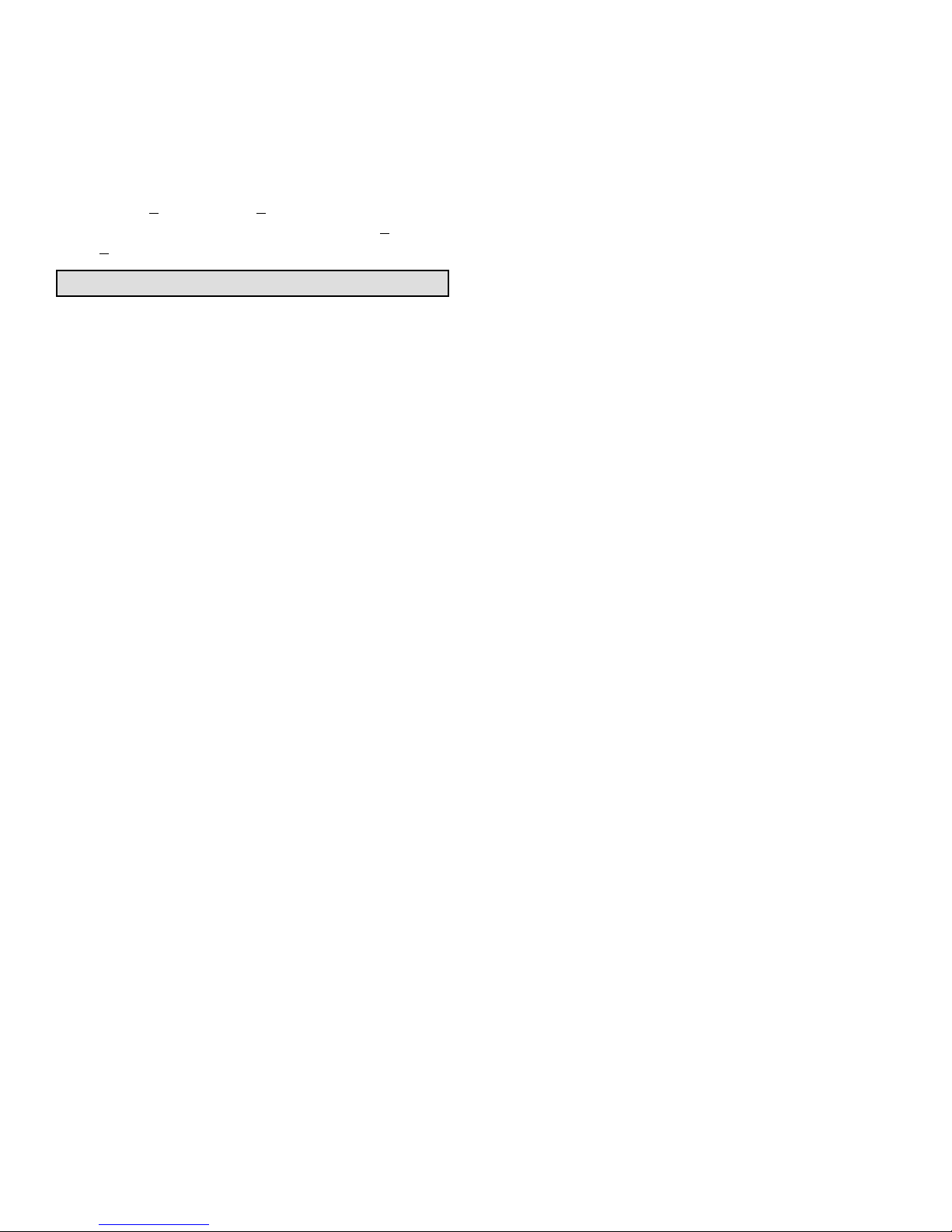
6 − Check amp−draw on outdoor fan motor.
Unit nameplate_______Actual_______.
7 − Inspect drain holes in coil compartment base and
clean if necessary.
NOTE − If owner complains of insufficient cooling, the unit
should be gauged and refrigerant charge checked. Refer to
section on refrigerant charging in this instruction.
Indoor Coil
1 − Clean coil if necessary.
2 − Check connecting lines, joints, and coil for evidence of
oil leaks.
3 − Check condensate line and clean if necessary.

Page 18
Indoor Unit
1 − Clean or change the filters.
2 - Lennox blower motors are prelubricated and permanent-
ly sealed. No more lubrication is needed.
3 − Adjust blower speed for cooling. Check the pressure
drop over the coil to determine the correct blower CFM.
Refer to the Lennox Engineering Handbook for indoor
unit blower CFM tables.
4 − Belt Drive Blowers − Check belt for wear and proper
tension.
5 − Check all wiring for loose connections.
6− Check for correct voltage at unit. (blower operating)
7 − Check amp−draw on blower motor.
Motor nameplate_______Actual_______.
Optional Accessories
Refer to the Engineering Handbook for optional accessories that may apply to this unit. The following may or may
not apply:
Loss of Charge Kit
High Pressure Switch Kit
Compressor Monitor
Compressor Crankcase Heater
Hail Guards
Mounting Bases
Timed Off Control
Stand−off Kit
Sound Cover
Low Ambient Kit
Monitor Kit
HP27 Check Points
Start−up and Performance Check List
Job Name
Job Location
Installer
Unit Model No.
Nameplate Voltage
Rated Load Ampacity
Maximum Fuse or Circuit Breaker
Refrigerant Lines:
Service Valves Fully Opened?
Outdoor Fan Checked?
Job No.
City
City
Serial No.
Date
State
State
Service Technician
Compressor
Outdoor Fan
Indoor Filter Clean?
Electrical Connections Tight?
Supply Voltage (Unit Off)
Vapor Pressure
Thermostat
Refrigerant Charge Checked?
Calibrated? Properly Set? Level?
Properly Insulated?
Voltage With Compressor Operating
Leak Checked?
Service Valve Caps Tight?
Indoor Blower RPM
Outdoor Coil Entering Air Temp.
Liquid Line Pressure
S.P. Drop Over Indoor (Dry)
Cooling
Vapor Pressure
Refrigerant Charge Checked?
Liquid Line Pressure
Heating
Sequence of Operation
Heating Correct Cooling Correct
 Loading...