

Lennox HP25 Series, HP25-211, HP25-261, HP25-311, HP25-461-463 Installation Instructions Manual
...
INSTALLATION
PRODUCT LITERATURE
1995 Lennox Industries Inc.
Dallas, Texas
HP25 HEAT PUMP UNIT
HP25 heat pump units are designed for expansion valve
systems only. They are not designed for RFC systems.
Refer to Lennox engineering handbook for expansion
valve kits which must be ordered separately.
INSTRUCTIONS
HP25 SERIES UNITS
HEAT PUMP UNITS
503,302M
6/95
Supersedes 503,247M
TABLE OF CONTENTS
HP25 HEAT PUMP UNIT 1. . . . . . . . . . . . . . . . . . . . . . . . . . . .
SHIPPING AND PACKING LIST 1. . . . . . . . . . . . . . . . . . . . . .
GENERAL INFORMATION 1. . . . . . . . . . . . . . . . . . . . . . . . . .
HP25 UNIT DIMENSIONS 2. . . . . . . . . . . . . . . . . . . . . . . . . .
HP25 PARTS ARRANGEMENT 3. . . . . . . . . . . . . . . . . . . . . .
SETTING THE UNIT 3. . . . . . . . . . . . . . . . . . . . . . . . . . . . . . . .
ELECTRICAL 4. . . . . . . . . . . . . . . . . . . . . . . . . . . . . . . . . . . . . .
PLUMBING 5. . . . . . . . . . . . . . . . . . . . . . . . . . . . . . . . . . . . . . .
REFRIGERATION 5. . . . . . . . . . . . . . . . . . . . . . . . . . . . . . . . . .
LEAK TESTING 6. . . . . . . . . . . . . . . . . . . . . . . . . . . . . . . . . . . .
EVACUATION 6. . . . . . . . . . . . . . . . . . . . . . . . . . . . . . . . . . . . .
START-UP 7. . . . . . . . . . . . . . . . . . . . . . . . . . . . . . . . . . . . . . . .
CHARGING 7. . . . . . . . . . . . . . . . . . . . . . . . . . . . . . . . . . . . . . .
SYSTEM OPERATION 9. . . . . . . . . . . . . . . . . . . . . . . . . . . . . .
DEFROST SYSTEM 9. . . . . . . . . . . . . . . . . . . . . . . . . . . . . . . .
MAINTENANCE 11. . . . . . . . . . . . . . . . . . . . . . . . . . . . . . . . . .
HP25 CHECK POINTS 12. . . . . . . . . . . . . . . . . . . . . . . . . . . . .
RETAIN THESE INSTRUCTIONS
FOR FUTURE REFERENCE
Litho U.S.A.
SHIPPING AND PACKING LIST
1- Assembled HP25 heat pump unit
Check unit for shipping damage. Consult last carrier
immediately if damage is found.
GENERAL INFORMATION
These instructions are intended as a general guide and
do not supersede national or local codes in any way.
Authorities having jurisdiction should be consulted be
fore installation.
IMPORTANT
The Clean Air Act of 1990 bans the intentional
venting of refrigerant (CFC's and HCFC's) as of July
1, 1992. Approved methods of recovery, recycling
or reclaiming must be followed. Fines and/or in
carceration may be levied for non-compliance.
WARNING
Product contains fiberglass wool.
Disturbing the insulation in this product during
installation, maintenance, or repair will expose
you to fiberglass wool. Breathing this may cause
lung cancer. (Fiberglass wool is known to the
State of California to cause cancer.)
Fiberglass wool may also cause respiratory, skin,
and eye irritation.
To reduce exposure to this substance or for further
information, consult material safety data sheets
available from address shown below, or contact
your supervisor.
Lennox Industries Inc.
P.O. Box 799900
Dallas, TX 75379-9900
Page 1
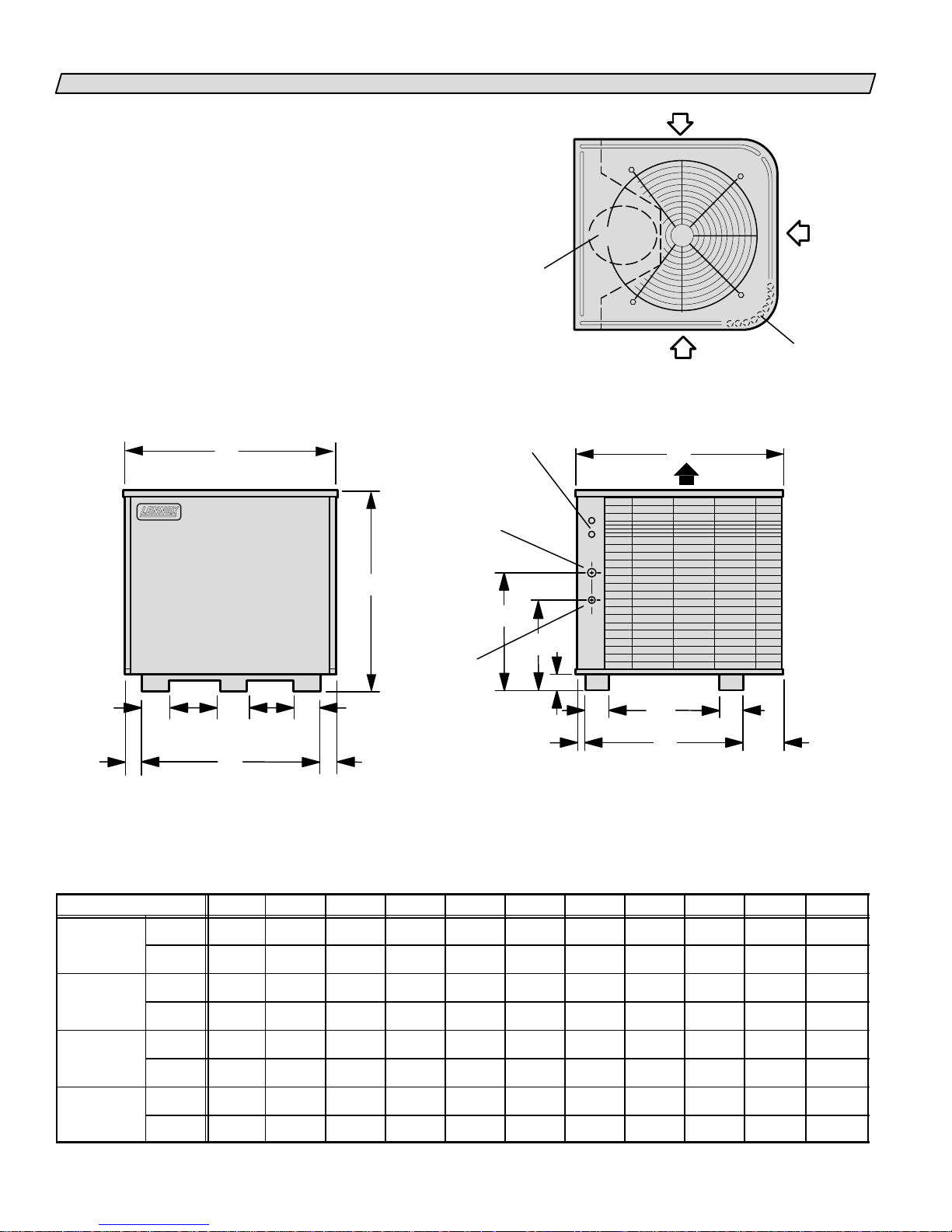
HP25 UNIT DIMENSIONS-INCHES (MM)
HP25211
HP25 311
HP25 511 513
HP25
HEAT PUMP UNIT
B
COMPRESSOR
ELECTRICAL
INLETS
VAPOR
LINE INLET
(HP25211460)
LIQUID
LINE INLET
(HP25510650)
INLET
INLET AIR
AIR
TOP VIEW
C
DISCHARGE AIR
INLET
AIR
COIL DRAIN
OUTLETS
(Around perimeter
of base)
A
LIQUID
LINE INLET
(HP25211460)
VAPOR
LINE INLET
(HP25510650)
KK
LL
47/8 (22)
GHH
FRONT VIEW
Model No. A B C D E F G H J K L
HP25211
HP25261
HP25311
HP25411413
in. 277/8 257/8 297/8 121/4 227/16 147/16 221/8 17/8 163/4 51/2 27/8
mm 708 657 759 311 570 367 562 48 425 140 73
in. 307/8 321/8 341/16 123/4 265/8 185/8 281/8 2 171/4 71/2 37/8
mm 784 816 865 324 676 473 714 51 438 191 98
J
23/4
(70)
D
13/8
(35)
4
(102)
F
E
SIDE VIEW
4
(102)
61/16
(154)
HP25461463
HP25511513
HP25651653
in. 347/8 321/8 341/16 133/4 265/8 185/8 281/8 2 181/4 71/2 37/8
mm 886 816 865 349 676 473 714 51 464 191 98
in. 447/8 321/8 341/16 291/4 265/8 185/8 281/8 2 203/4 71/2 37/8
mm 1140 816 865 743 676 473 714 51 527 191 98
Page 2
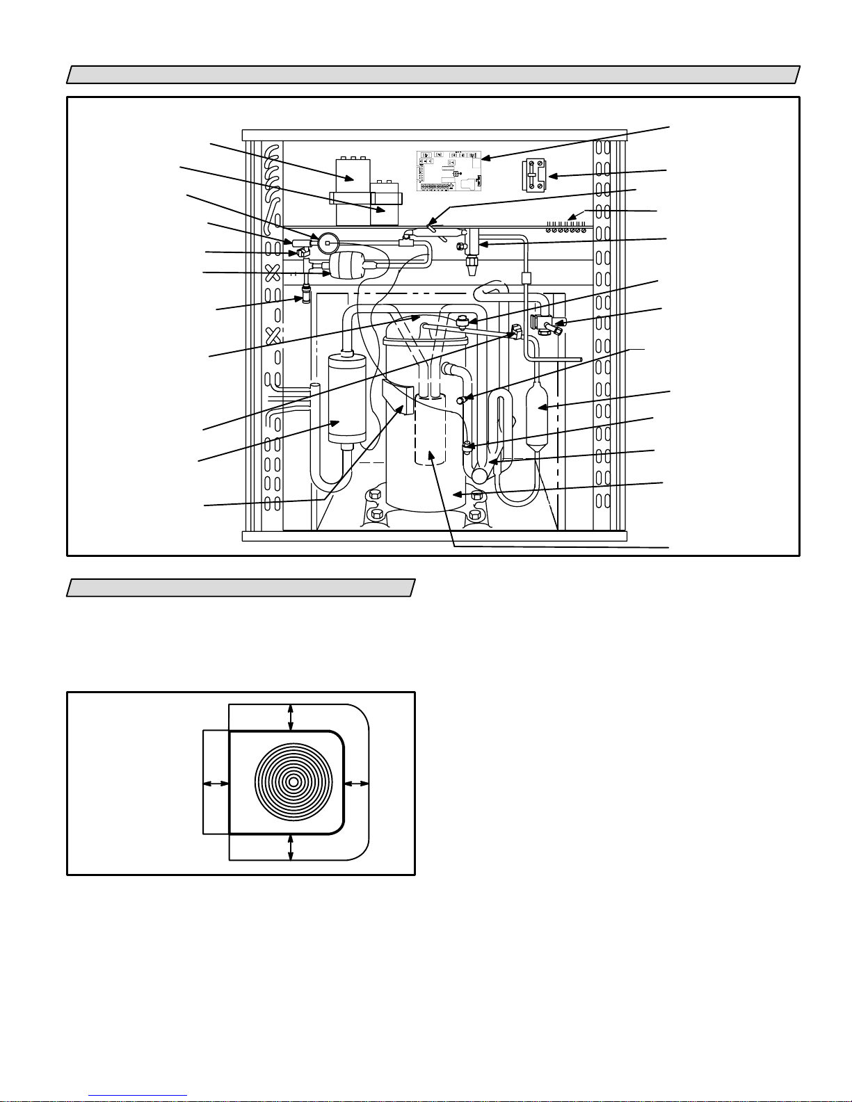
HP25 PARTS ARRANGEMENT
HP25 UNIT COMPONENTS
DUAL CAPACITOR
(Single-Phase Units)
FAN CAPACITOR
(Three-Phase Units)
EXPANSION
VAL VE
DISTRIBUTOR
DEFROST
THERMOSTAT
FILTER/DRIER
WITH
INTERNAL CHECK VALVE
FACTORY
CHARGE
PROCESS PORT
COMPRESSOR
TEMPERATURE
SENSOR
HP25211 THRU 460 ONLY
SERVICE LIGHT
THERMOSTAT
CHARGE
COMPENSATOR
COMPRESSOR
TERMINAL BOX
FIGURE 1
SETTING THE UNIT
HP25 heat pump units are approved and warranted
only for installation with specially matched indoor
coils, L10 or L15 line sets, and refrigerant control de
vices as designated by Lennox. Refer to the Lennox En
gineering Handbook for approved systems.
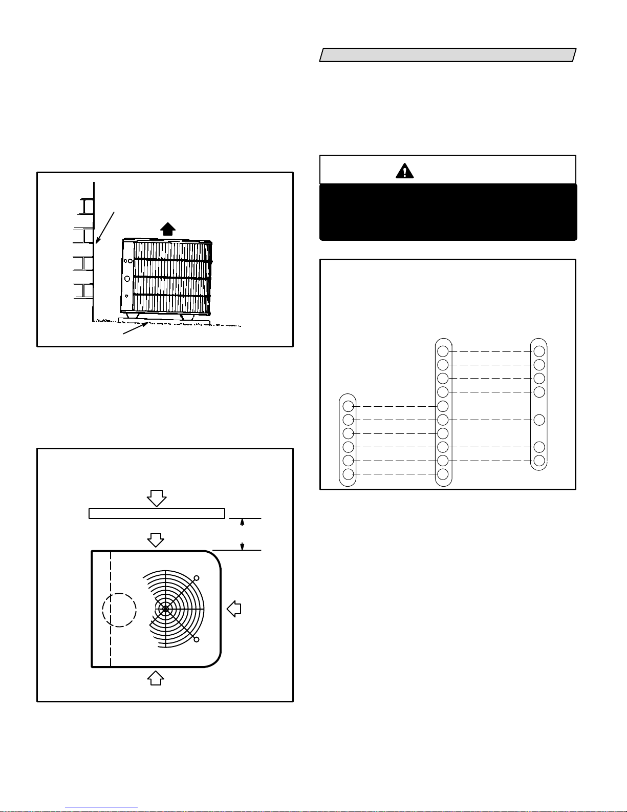
INSTALLATION
CLEARANCES
NOTE-48"
(1219mm)
clearance required
on top of unit.
*One side dimension
may be 12" (305mm).
36"
(914mm)
*36"
(914mm)
FIGURE 2
Heat pump units operate under a wide range of weath
er conditions; therefore, several factors must be con
sidered when positioning the outdoor unit.
*36"
(914mm)
*36"
(914mm)
DEFROST CONTROL
CONTACTOR
THERMOMETER WELL
TERMINAL STRIP
LIQUID LINE
SERVICE VALVE
AND GAUGE PORT
HIGH PRESSURE SWITCH
VAPOR LINE
SERVICE VALVE
AND GAUGE PORT
SUCTION GAUGE PORT
MUFFLER
EXPANSION VALVE
SENSING BULB
REVERSING VALVE
AND SOLENOID
COMPRESSOR
ACCUMULATOR
HP25510 AND
-650 ONLY
1- Place a sound-absorbing material, such as Iso
mode, under the unit if it will be installed in a loca
tion or position that will transmit sound or vibra
tion to the living area or adjacent buildings.
2- Mount unit high enough above ground or roof to al
low adequate drainage of defrost water and prevent
ice build-up.
3- In heavy snow areas, do not locate unit where drift
ing will occur. The unit base should be elevated
above the depth of average snows.
NOTE-Elevation of the unit may be accomplished
by constructing a frame using suitable materials. If
a support frame is constructed, it must not block
drain holes in unit base.
4- When installed in areas where low ambient tem
peratures exist, locate unit so winter prevailing
winds do not blow directly into outdoor coil.
5- Locate unit away from overhanging roof lines
which would allow water or ice to drop on, or in
front of, coil or into unit.
Page 3
Slab Mounting (See figure 3)
When installing unit at grade level, top of slab should
be high enough above the grade so that water from
higher ground will not collect around unit. Slab should
have a slope tolerance away from the building of 2 de
grees or 2 inches per 5 feet (51mm per 1.5m). This will
prevent ice build-up under unit during a defrost cycle.
Refer to roof mounting section for barrier construction
if unit must face prevailing winter winds.
SLAB MOUNTING
BUILDING
STRUCTURE
MOUNTING SLAB
DISCHARGE
AIR
2 DEGREES or 2 IN. PER 5 FT.
(51mm per 1.5m)
TOLERANCE AWAY FROM
BUILDING STRUCTURE
SLOPE
GROUND LEVEL
FIGURE 3
Roof Mounting (See figure 4)
If unit coil cannot be mounted away from prevailing
winter winds, a wind barrier should be constructed.
Size barrier at least the same height and width as out
door unit. Mount barrier 24 inches (610mm) from the
sides of the unit in the direction of prevailing winds.
ROOFTOP APPLICATION
WIND BARRIER CONSTRUCTION
PREVAILING WINTER WINDS
WIND BARRIER
INLET AIR
24"
(610mm)
ELECTRICAL
Wiring must conform to the National Electric Code
(NEC) and local codes. Application diagram is included
in this instruction (see figure 6) and in indoor unit
instructions. Refer to figure 5 for thermostat designa
tions. Refer to unit rating plate for minimum circuit am
pacity and maximum fuse size.
WARNING
Unit must be grounded in accordance with
national and local codes.
Electric Shock Hazard.
Can cause injury or death.
HP25 and BLOWER UNIT
THERMOSTAT DESIGNATIONS
(WITH OR WITHOUT AUXILIARY HEAT)
(Some connections may not apply.
Refer to specific thermostat and indoor unit.)
HP25ThermostatIndoor
Blower
Unit
EMERGENCY HEAT
E
C
W2
R
W1
G
COMMON
2ND STAGE AUX. HEAT
POWER
1ST STAGE AUX. HEAT
INDOOR BLOWER
FIGURE 5
1- Provide line voltage power supply to unit from a
properly sized disconnect switch. See figure 6.
AMBIENT SENSOR
T
SERVICE LIGHT
L
REVERSING VALVE
O
COMPRESSOR
Y1
E
C
W2
R
W1
G
COMMON
POWER
DEFROST SENSING/
1ST STAGE AUX. HEAT
T
L
O
Y1
C
R
W1
INLET AIR
FIGURE 4
INLET
AIR
2- Install room thermostat (ordered separately) in
the conditioned area. Locate where it will not be
affected by sunlight, drafts or vibration. Do not
install on an outside wall. A position approxi
mately 5 feet (1.5m) from the floor and near the
center of the conditioned area is most desirable.
3- Provide low voltage wiring from outdoor to indoor
unit and from thermostat to indoor unit as indi
cated on the field wiring diagram in this instruc
tion. See figure 6.
4- Ground unit either through supply wiring or with
an earth ground.
Page 4
 Loading...