

SERVICE
UNIT
INFORMATION
Corp. 9428–L10
Replaces Corp. 9330-L4
HP23 SERIES UNITS
HP23
Litho U.S.A.
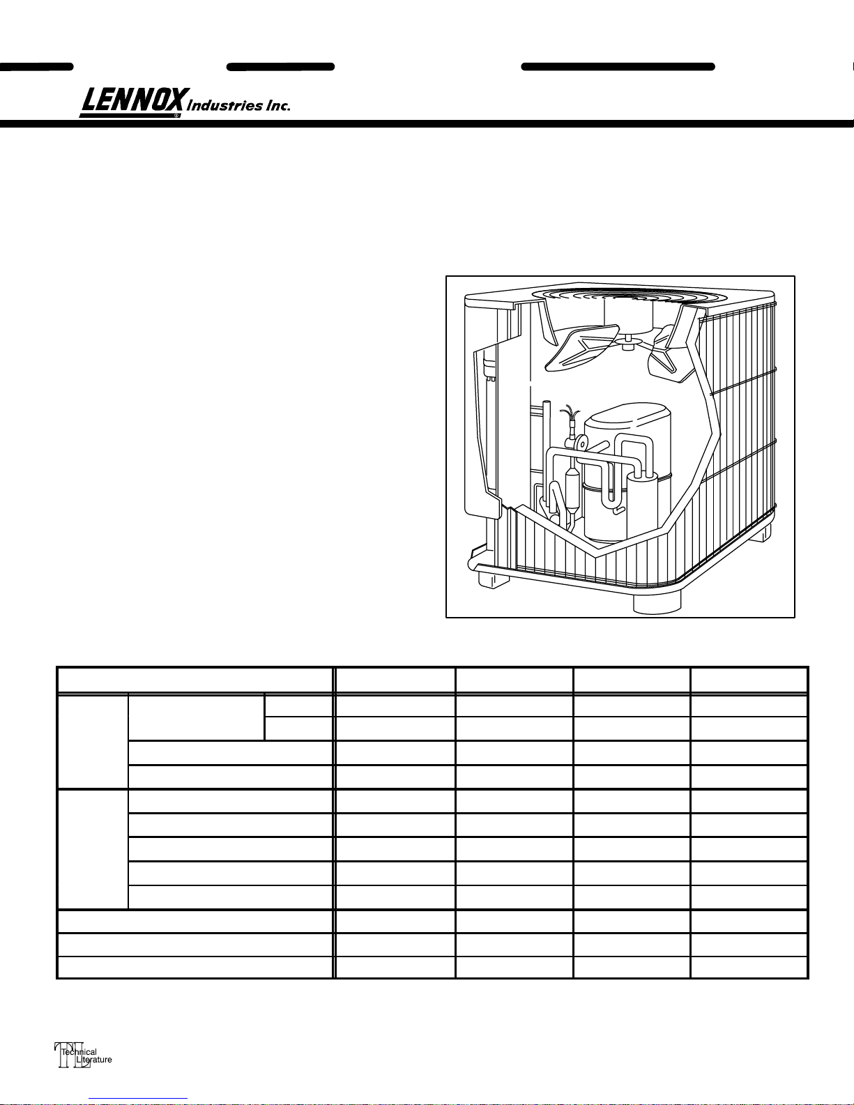
The HP23 is a high-efficiency residential
split-system heat pump. Extra large outdoor coil,
coil circuiting and high outdoor coil air volume
result in a high SEER rating (minimum of 10.0).
HP23-141 through HP23-510 units are designed for
use with an expansion valve or RFCIII system in the
indoor unit. HP23-651/653 units are designed for use
with an expansion valve only in the indoor unit.
All compressors are hermetically sealed for
trouble-free operation and long service life.
Compressor components are spring mounted within
the sealed housing. The compressor is installed in the
unit on resilient rubber mounts to assure quiet,
vibration-free operation. A built-in limit protects the
compressor from excessive current and temperatures.
A high pressure safety limit is furnished as standard.
HP23–211 through HP23–650 models are furnished with
crankcase heaters as standard equipment. The heater
prevents liquid from accumulating in the compressor.
The heater is temperature-actuated and operates only
when required. A crankcase heater for HP23-141 units is
optional, but suction accumulator is factory installed.
Several models are available in sizes ranging from 1
through 5 tons.
This manual is divided into sections which discuss major
components refrigerant system, charging procedures,
maintenance, and operation sequence.
Canadian specifications are marked (CAN).
All specifications in this manual are subject to change.
SPECIFICATIONS
Model No. HP23-141 HP23-211 HP23-261 HP23-311
Outer coil 12.60 12.60 12.60 14.70
Net face area (sq. ft.)
Condenser
Coil
Condenser
Fan
*Refrigerant — 22 charge furnished 5 lbs. 3 oz. 5 lbs. 6 oz. 6 lbs. 2 oz. 7 lbs. 3 oz.
Liquid line (o.d. in.) connection (sweat) **3/8 ***3/8 ***3/8 3/8
Suction line (o.d. in.) connection (sweat) 1/2 5/8 5/8 3/4
*Refrigerant charge sufficient for 20 ft. length of refrigerant lines.
**3/8” x 1/4” reducer furnished to adapt to 1/4 field fabricated line set.
***3 /8” x 5/16” reducer furnished to adapt unit to 5/16” line set.
Tube diameter (in.) & no. of rows 3/8 — 1 3/8 — 1 3/8 — 1 3/8 — 1
Fins per inch 20 20 20 20
Diameter (in.) & no. of blades 20 — 3 20 — 3 20 — 3 20 — 3
Motor hp 1/6 1/6 1/6 1/6
Cfm 2630 2630 2630 2665
Rpm 840 840 840 850
Watts 210 210 210 210
Inner coil - - - - - - - - - - - - - - - -
Page 1
1993 Lennox Industries Inc.
SPECIFICATIONS (contd.)
Net f
)
Cond
Fan
Model No. HP23-411/HP23-413 HP23-461/HP23-463 HP23-511/HP23-513 HP23-651/HP23-653
Condenser
Coil
enser
*Refrigerant — 22 charge furnished 7lbs. 14oz. / 7lbs. 5oz. 8 lbs. 3 oz. 9 lbs. 6 oz. 12 lbs. 13 oz.
Liquid line (o.d. in.) connection (sweat) 3/8 3/8 3/8 3/8
Suction line (o.d. in.) connection (sweat) 3/4 7/8 7/8 1-1/8
*Refrigerant charge sufficient for 20 ft. length of refrigerant lines.
ace area (sq. ft.
Tube diameter (in.) & no. of rows 3/8 — 1.3 3/8 — 1.0 3/8 — 1.3 3/8 — 2.0
Fins per inch 20 20 20 20
Diameter (in.) & no. of blades 20 — 3 20 — 4 24 — 4 24 — 4
Motor hp 1/6 1/4 1/4 1/4
Cfm 2600 3980 3980 3950
Rpm 845 840 830 825
Watts 200 350 340 370
Outer coil 14.70 20 20.00 20.00
Inner coil 3.9 - - - - 6.3 19
ELECTRICAL DATA
Model No. HP23-141 HP23-211 HP23-261 HP23-311-1 HP23-311-2 HP23-411 HP23-411–2
Line voltage data 208/230v 60hz-1ph
Rated load amps 5.0 8.1 10.9 12.2 13.7 16.3 16.2
Compressor Power factor .97 .99 .95 .97 0.99 .99 .91
Locked rotor amps 26.3 49.0 61.0 71.0 75.0 86.7 96.0
Condenser Coil
Fan Motor
Rec. max. fuse or circuit breaker size
(amps)
*Minimum circuit ampacity 7.4 11.3 14.8 16.4 18.2 21.5 21.3
*Refer to National Electrical Code manual to determine wire, fuse and disconnect size requirements.
NOTE — Extremes of operating range are plus 10% and minus 5% of line voltage.
Full load amps 1.1 1.1 1.1 1.1 1.1 1.1 1.1
Locked rotor amps 1.7 1.7 1.7 1.7 1.7 1.7 1.7
15 15 25 25 30 35 35
ELECTRICAL DATA
Model No. HP23-413 HP23-461-1 HP23-463-1
Line voltage data — 60hz.
Rated load amps 11.6 5.1 18.6 12.7 5.8
Compressor Power factor .88 .88 .94 .82 .82
Locked rotor amps 65.1 32.8 102.0 91.0 42.0
Condenser Coil
Fan Motor
Rec. max. fuse or circuit breaker size (amps) 25 15 40 30 15
*Minimum circuit ampacity 15.6 7.0 25.0 17.6 8.4
*Refer to National Electrical Code manual to determine wire, fuse and disconnect size requirements.
NOTE — Extremes of operating range are plus 10% and minus 5% of line voltage.
Full load amps 1.1 0.6 1.7 1.7 1.1
Locked rotor amps 1.7 0.9 3.1 3.1 2.2
208/230
3ph
460v
3ph
208/230v 1ph
208/230v
3ph
460v
3ph
ELECTRICAL DATA
Model No. HP23-511 HP23-513 HP23-651 HP23-653
Line voltage data — 60 hz 208/230v 1ph 208/230v 3ph 460v 3ph 208/230v 1ph 208/230v 3ph 460v 3ph
Rated load amps 24.4 16.1 8.4 30.8 17.4 9.7
Compressor Power factor .98 .78 .78 .98 .78 .78
Locked rotor amps 135.0 137.0 68.0 147.0 150.0 73.0
Condenser Coil
Fan Motor
Rec. max. fuse or circuit breaker size (amps) 50 35 15 60 40 20
*Minimum circuit ampacity 32.2 21.9 10 40.2 23.5 13.3
*Refer to National Electrical Code manual to determine wire, fuse and disconnect size requirements.
NOTE — Extremes of operating range are plus 10% and minus 5% of line voltage.
Full load amps 1.7 1.7 1.1 1.7 1.7 1.1
Locked rotor amps 3.1 3.1 2.2 3.1 3.1 2.2
Page 2
I – UNIT INFORMATION
HP23 units are available in 1, 1 -1/2, 2, 2 -1/2, 3, 3 -1/2, 4
and 5 ton capacities.
All major components (indoor blower/coil) must be
matched according to Lennox recommendations for
the compressor to be covered under warranty. Refer to
the Engineering Handbook for approved system
matchups. A misapplied system will cause erratic
operation and can result in early compressor failure.
II – UNIT COMPONENTS
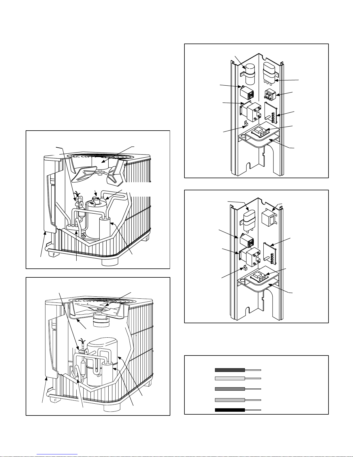
Unit components are illustrated in figures 1 and 2.
HP23-141, -210, -260, -310 and -410
EXPANSION
VALVE
UNIT COMPONENTS
OUTDOOR
FAN/MOTOR
A – Control Box (Figures 3 and 4)
HP23 UNIT CONTROL BOX SINGLE PHASE UNITS
START CAPACITOR
(C7)
DUAL CAPACITOR
DEFROST
RELAY (K4)
COMPRESSOR
CONTACTOR
(K1)
GROUNDING
LUG
(C12)
POTENTIAL
RELAY (K31)
DEFROST
CONTROL
CMC1
TIMED OFF
CONTROL (A4)
HP24-651 ONLY
LOW VOLTAGE
MAKEUP
AREA
CONTROL
BOX
COMPRESSOR
HP23-141 SHOWN
REVERSING VALVE
SUCTION
MUFFLER HP23-141
ONLY
ACCUMULATOR
HP23-141 ONLY
FIGURE 1
HP23-460, -510 and -650 UNIT COMPONENTS
EXPANSION
VALVE
FAN
SPIDER
OUTDOOR
FAN/MOTOR
FIGURE 3
HP23 UNIT CONTROL BOX THREE PHASE UNITS
FAN CAPACITOR
(C1)
DEFROST
RELAY (K4)
COMPRESSOR
CONTACTOR
(K1)
GROUNDING
LUG
TRANSFORMER(T5)
“J” VOLTAGE
UNITS ONLY
DEFROST
CONTROL
CMC1
TIMED OFF
CONTROL (A4)
HP24-653 ONLY
LOW VOLTAGE
MAKEUP
AREA
FIGURE 4
A low voltage make up area is provided for thermostat
field wiring. Field thermostat wiring is made to color
coded pigtail connections as illustrated in figure 5.
CONTROL BOX
REVERSING VALVE
FIGURE 2
COMPRESSOR
ACCUMULATOR
Page 3
THERMOSTAT WIRING IDENTIFICATION
RED
YELLOW
ORANGE
BEIGE
FROM OUTDOOR UNIT
BLACK
24V (POWER) INPUT
TO OUTDOOR UNIT
(COMPRESSOR)
(REVERSING VALVE)
INPUT
(ELECTRIC HEAT)
DEFROST OUTPUT
(COMMON)
FIGURE5
INPUT
THERMOSTAT
TO INDOOR UNIT/
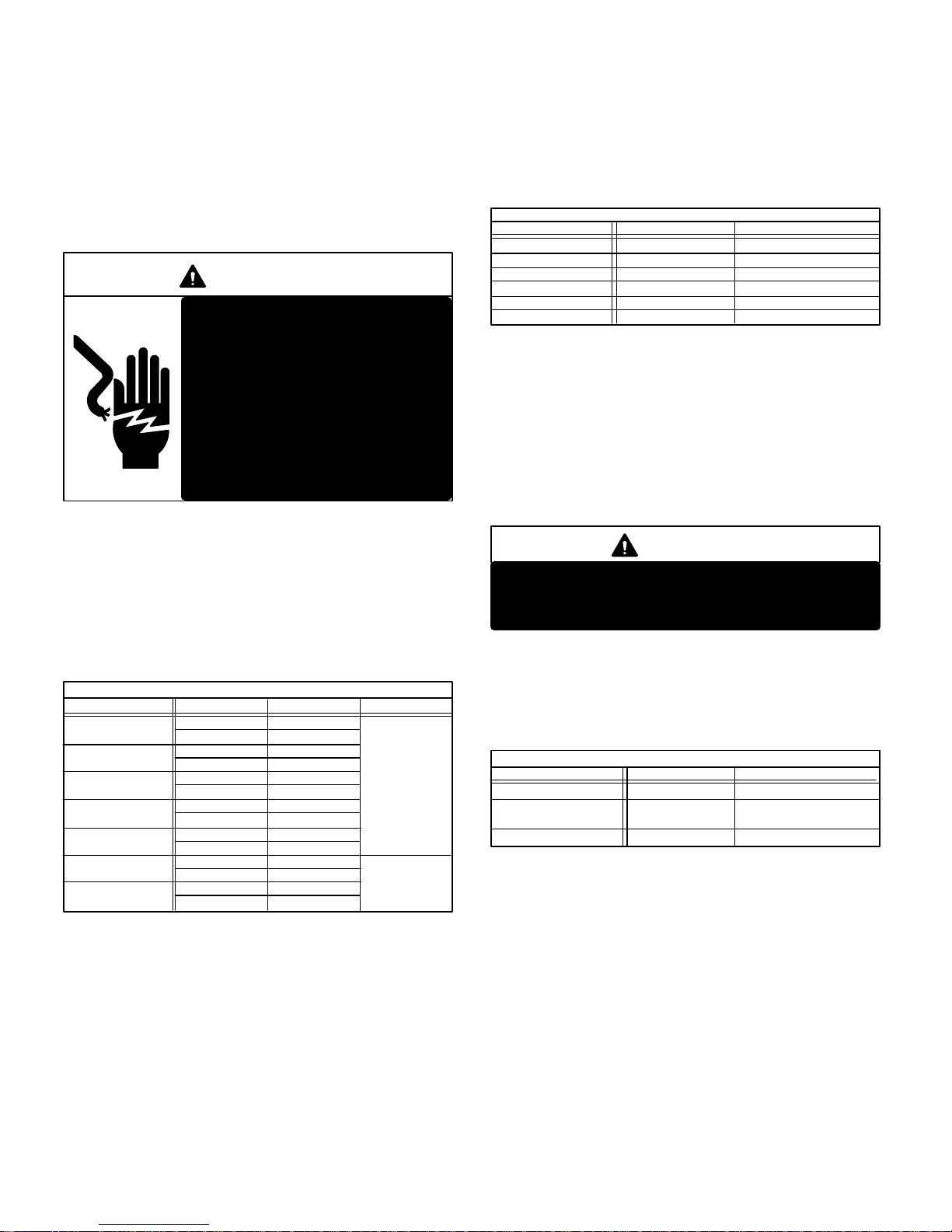
1 – Compressor Contactor K1
The compressor is energized by a contactor located in
the control box. See figures 3 and 4. Contactors are
SPST in single phase units and 3PST in three phase
units. K1 is energized by the indoor thermostat
terminal Y (24V). HP23 units are not equipped with a line
voltage to 24V transformer. All 24 VAC controls are
powered by the indoor unit. Refer to unit wiring diagram.
DANGER
Shock Hazard
All single phase HP23 units use
single-pole contactors. One leg of
compressor, capacitor and outdoor
fan are connected to line voltage at
all times. Potential exists for
electrical shock resulting in injury
or death. Remove all power at
disconnect before servicing.
Can cause personal injury or death.
2 – Dual Capacitor C12
The compressor and fan in single phase units use
permanent split capacitor motors. The capacitor is
located inside the unit control box (see figure 3). A single
“dual” capacitor (C12) is used for both the fan motor and
the compressor (see unit wiring diagram). The fan side
and the compressor side of the capacitor have different
MFD ratings. See table 1 for dual capacitor ratings.
HP23 (C12) DUAL CAPACITOR RATING
Unit MFD VAC
HP23–141
HP23–211/261
HP23–311-1/411
HP23–311-2
HP23–411-2
HP23–461
HP23–511/651
3 – Potential Relay K31 (Start)
All single phase units use a potential relay which
controls the operation of the starting circuit. The
potential relay is located inside the unit control box (see
figure 3). The relay is normally closed when contactor
K2 is de-energized. When K1 energizes, the compressor
immediately begins start-up. K31 remains closed
during compressor start-up and start capacitor C7
remains in the circuit. As the compressor gains speed,
K31 is energized. When K31 energizes, the contacts
open and start capacitor C7 is taken out of the circuit.
TABLE 1
Terminal
FAN
HERM
FAN
HERM
FAN
HERM
FAN
HERM
FAN
HERM
FAN
HERM
FAN
HERM
25
35
45
35
40
10
40
10
60
5
5
5
5
5
370
440
4 – Start Capacitor C7
All single phase units use a start capacitor (C7). C7 is
located inside the unit control box (see figure 3). C7 is
wired in parallel with the compressor side of the dual
capacitor. See table 2 for start capacitor ratings.
TABLE 2
HP23 START CAPACITOR RATING (C7)
Unit MFD VAC
HP23–141/211/261
HP23–311-1/411 88–108 330
HP23–311-2 145–175 330
HP23–411 (CAN)
HP23–411–2/461/511
HP23–651 270-324 330
88–108 250
25088–108
189-227 330
5 – Timed Off Control A4 (–651 / –653 only)
A time delay (A4) located in the control box is used on
the HP23-650-2 series. See figures 3 and 4. The time
delay is electrically connected between thermostat
terminal Y and the compressor contactor. After cooling
demand has stopped, A4 begins counting for five
minutes. During the timing period, A4 disables the
compressor contactor. Thermostat demand will have
no effect on the unit.The unit cannot operate. After the
delay, the compressor contactor can be energized.
DANGER
Do not attempt to repair this control. Unsafe
operation will result. If the control has failed,
replace the control.
6 – Fan Capacitor C1
The fan in three-phase units uses a single phase
permanent split capacitor motor. A single capacitor C1 is
used for the fan motor. C1 is located inside the unit
control box (see figure 4). Table 3 shows the ratings of C1.
HP23 FAN CAPACITOR RATING (C1)
Unit MFD VAC
HP23–413Y,G
HP23–463/513/653G
HP23-513,653J
HP23-463/513/653Y 10 370
7 – Transformer T5
Transformer T5 is used on all “J” voltage units. T5 is
used as a step-down transformer for fan B4. T5 is rated at
3.4 VA with a 575 volt primary and a 460 volt secondary.
8 – Defrost Relay K4
The defrost relay controls defrost. The relay is a 3PDT
relay powered 24 VAC from the thermostat. K4 is
enabled during both cooling and heating modes
(except emergency heat). It is only powered when the
defrost control is calling for defrost. When energized,
the reversing valve and indoor auxiliary heat are
energized. Simultaneously, the outdoor fan is
de-energized. K4 latches in for the duration of the
defrost period. Refer to unit wiring diagram and
operation sequence in the back of this manual.
TABLE 3
5 370
7.5 370
Page 4
9 – Defrost Control CMC1
The CMC1 defrost control (figure 6) is a solid state control
manufactured by Hamilton Standard. The control
provides automatic switching from normal heating
operation to defrost mode and back. The control
provides 14 minute defrost periods at 30, 60 or 90 minute
field changeable intervals. The control monitors
thermostat demand and “holds” the timer in place
between thermostat demand. A set of diagnostic pins are
also provided for troubleshooting the unit.
The control contains a solid state timer which switches
an external defrost relay through 1/4” male spades
mounted on the control’s circuit board. When the
defrost thermostat closes (call for defrost), the defrost
timer initiates a 30, 60 or 90 minute (depending on how
the control is preset) timing sequence. If the defrost
thermostat remains closed when the timing sequence
ends, the defrost relay is energized and defrost begins.
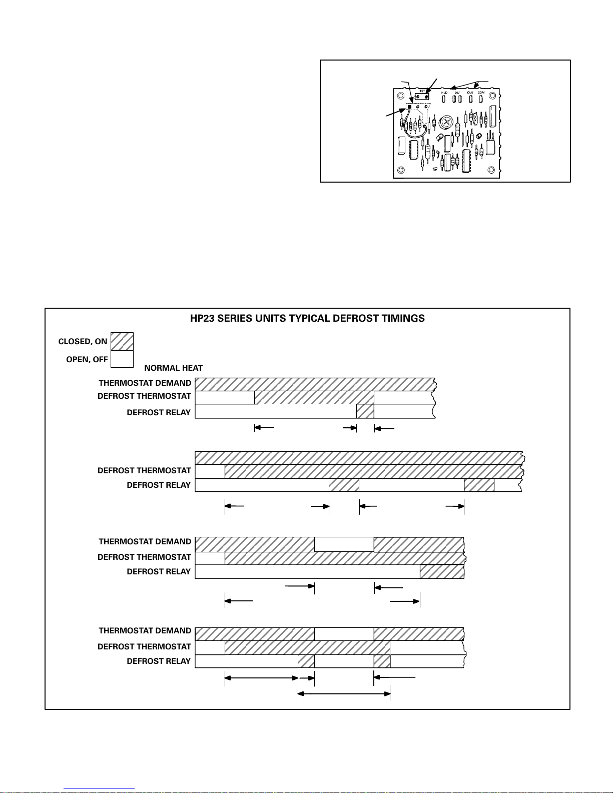
HP23 SERIES UNITS TYPICAL DEFROST TIMINGS
Note – Control begins timing at 0 when defrost thermostat closes. Defrost is terminated when defrost
CLOSED, ON
OPEN, OFF
THERMOSTAT DEMAND
DEFROST THERMOSTAT
THERMOSTAT DEMAND
DEFROST THERMOSTAT
relay is de–energized. Anytime defrost thermostat opens, defrost relay is immediately de–energized,
NORMAL HEATING OPERATION: DEFROST TERMINATED BY DEFROST THERMOSTAT
DEFROST RELAY
NORMAL HEATING OPERATION: DEFROST TERMINATED BY TIME
DEFROST RELAY
defrost timer resets and “HOLD” function stops.
30/60/90 MINUTES
SOLID STATE DEFROST CONTROL CMC1
Timing Pins
Timing
Jumper
Troubleshooting Pins
30 60 90
Control Terminals
FIGURE 6
A defrost period can last up to 14 minutes and can be
terminated two ways. If the defrost thermostat does
not open within 14 minutes after defrost begins, the
timer will de–energize the defrost relay and the unit
will resume normal operation. If the defrost
thermostat opens during the 14 minute defrost period,
the defrost relay is de–energized and the unit resumes
normal operation. Refer to figure 7.
DEFROST THERMOSTATOPEN WITHIN 14 MINUTES
NORMAL HEATING OPERATION INTERRUPTED BY THERMOSTAT DEMAND: “HOLD” FUNCTION
THERMOSTAT DEMAND
DEFROST THERMOSTAT
DEFROST RELAY
DEFROST PERIOD INTERRUPTED BY THERMOSTAT DEMAND: “HOLD” FUNCTION
THERMOSTAT DEMAND
DEFROST THERMOSTAT
DEFROST RELAY
30/60/90 MINUTES 14 MIN. 30/60/90 MINUTES
DEFROST THERMOSTAT
MUST REMAIN CLOSED
FOR TIMER TO REMAIN
IN “HOLD”
“HOLD” TIME
30/60/90 MINUTES PLUS “HOLD” TIME
DEFROST THERMOSTAT
MUST REMAIN CLOSED
FOR TIMER TO REMAIN
IN “HOLD”
“HOLD” TIME
30/60/90 MINUTES
14 MIN. PLUS “HOLD” TIME
FIGURE 7
Page 5
Defrost Control Components
1– Timing Pins 30, 60, 90
Each of these pins provides a different timed
interval between defrosts. A jumper connects the
pins to circuit board pin W1. Table 4 shows the
timings of each pin. The defrost interval can be field
changed to 30, 60 or 90 minutes. The defrost period
(14 minutes) cannot be changed. To change the
interval between defrosts, simply remove the
jumper from the pin it is connected to and
reconnect the jumper to one of the other available
pins (see figure 8).
TABLE 4
CMC1 DEFROST
CONTROL
TIMINGS
NORMAL
OPERATION
“TST” PINS
JUMPER
TOGETHER
INTERVAL BETWEEN DEFROSTS
WITH JUMPER CONNECTED TO:
30 60 90
30 + 3 60 + 6 90 + 9 14 + 1.4
MIN. MIN. MIN. MIN.
7 + 0.7 14 + 1.4 21 + 2.1 3.3 + 0.3
SEC. SEC. SEC. SEC.
DEFROST
TIME
4– “HLD” Terminal
Terminal “HLD” holds the internal timer in place
between thermostat demands and allows the unit
to continue timing upon resumption of thermostat
demand. Terminal “HLD” is connected directly to
thermostat demand.
NOTE – Hold function operates between thermostat
demands only when defrost thermostat is closed. This
is the only time that the timer is operating.
5– “TST” Pins
Each board is equipped with a set of test pins for
use in troubleshooting the unit. When jumpered
together, these pins reduce the control timing to
about 1/256 original time (see table 4 and figure 9).
IMPORTANT
Control will begin test mode only if normal load is
applied to control terminals. Do not attempt to
operate or test control out of unit.
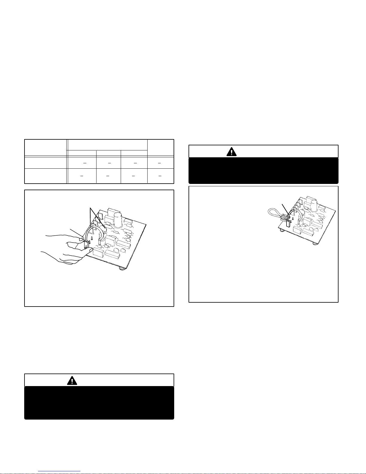
DEFROST CONTROL TIMING CHANGES
WARNING – AVOID CONTACT WITH OTHER CONTROL TERMINALS OR CONTROL COMPONENTS.
WARNING – DO NOT
CONNECT TIMING
JUMPER TO EITHER
“TST” PIN.
TO CHANGE CONTROL TIMINGS:
1– Turn off all power to the unit to avoid circuit board damage.
2– Grasp wire connector firmly with fingers.
3–
Gently
4– Select new timing pin. DO NOT SELECT A “TST” PIN.
5– Gently push connector onto desired pin (see Table 4 for timings).
6– Turn on power to unit.
pull connector from pin.
FIGURE 8
2– Timing Jumper
The timing jumper is a factory installed jumper
on the circuit board used to connect pin W1 to
one of the three timing pins. The jumper may be
connected to any one of the timing pins but must
never be connected to either of the “TST” pins.
See Caution below.
CAUTION
3– “COM” Terminal
Terminal “COM” provides 24VAC Common.
DEFROST CONTROL TEST MODE
WARNING – AVOID CONTACT WITH
OTHER CONTROL TERMINALS OR
CONTROL COMPONENTS.
TO PLACE CONTROL
1– Turn off all power to avoid
2– Make sure all control terminals are
3– Connect jumper to “TST” pins as shown.
4– Turn indoor thermostat to heat mode and adjust to highest
5– Turn on power to unit.
6– See Table 4 for control timings in “TST” mode.
7– Be sure to turn off power and remove jumper when test is com-
IN TEST MODE:
damaging the circuit board.
connected as shown on unit wiring
diagram before attempting to place control in
test mode. See NOTE below.
NOTE – Control will not go into test mode when disconnected
from unit. Unit load must be applied to control terminals before
the control will go into test mode.
temperature setting.
plete. Turn on power and re–adjust thermostat.
FIGURE 9
6– “24V” Terminal
Terminal “24V” receives 24VAC from the control
transformer through the defrost thermostat. This
terminal powers the control’s internal timer and
relays. Terminal “24V” is powered only when there is
a call for defrost (defrost thermostat closed). The
timer begins timing at 0 only after terminal “24V”
receives power.
7– “OUT” Terminal
Terminal “OUT” controls defrost when connected
to one side of the defrost relay coil. An internal
relay connected to terminal “OUT” closes to allow
external defrost relay to energize and initiate
defrost. At the end of the defrost period, the
internal relay connected to terminal “OUT” opens
to de-energize the external defrost relay.
Page 6
 Loading...