


Corp. 9434−L12
Service Literature
Revised 07−2007
HP21 SERIES UNITS INCLUDING TSC−2, TSC−3 AND TSC-6
The HP21 is a high efficiency residential split-system heat
pump with a two-speed compressor. Early models include
HP21−411, −511 and −651. Late models built after March 1,
2000 include HP21−36, −48 and −60. All models are available in sizes ranging from 3 through 5 tons in either single
or three-phase configuration. Early and late models feature
solid-state two-speed control and new solid-state demand
defrost control. The two-speed control regulates compressor speed in response to thermostat demand during
cooling mode. Compressor speed is regulated by outdoor
air temperature during heating mode. The defrost control
monitors outdoor air temperature and liquid line temperature to determine when defrost is needed. The series uses
conventional heat pump circuitry with expansion valves in
the outdoor and indoor units.
This manual is divided into sections which discuss the components, refrigerant system, charging procedures,
maintenance and operation sequences. All specifications
in this manual are subject to change.
DANGER
HP21
EARLY/LATE MODEL
TABLE OF CONTENTS
General 1. . . . . . . . . . . . . . . . . . . . . . . . . . . . . . . . . . . . .
Electric Shock Hazard.
May cause injury or death.
Line voltage is present at all components when unit is not in operation on
units with single pole contactors.
Disconnect all remote electrical power
supplies before opening unit panel.
Unit may have multiple power supplies.
WARNING
Improper installation, adjustment, alteration, service
or maintenance can cause property damage, personal injury or loss of life. Installation and service must
be performed by a qualified installer or service
agency.
WARNING
Refrigerant can be harmful if it is inhaled. Refrigerant
must be used and recovered responsibly.
Failure to follow this warning may result in personal injury or death.
Specifications / Electrical 2. . . . . . . . . . . . . . . . . . . . . .
I Application 3. . . . . . . . . . . . . . . . . . . . . . . . . . . . . . . . .
II Unit Components 3. . . . . . . . . . . . . . . . . . . . . . . . . . .
TSC−2 Control 6. . . . . . . . . . . . . . . . . . . . . . . . . . . . .
TSC−3 Control 10. . . . . . . . . . . . . . . . . . . . . . . . . . . . .
TSC−6 Control 11. . . . . . . . . . . . . . . . . . . . . . . . . . . . .
III Refrigerant System 20. . . . . . . . . . . . . . . . . . . . . . . . .
IV Charging 23. . . . . . . . . . . . . . . . . . . . . . . . . . . . . . . . . .
V Maintenance 25. . . . . . . . . . . . . . . . . . . . . . . . . . . . . .
VI Miscellaneous 26. . . . . . . . . . . . . . . . . . . . . . . . . . . . .
VII Wiring Diagrams and Operating Sequence 27. . . .
Page 1
© 1994 Lennox Industries Inc.

SPECIFICATIONS
Model No.
Face area (sq.ft.)
outside / inside
Outdoor Coil
Outdoor Fan
Refrigerant−22 (charge furnished)
Liquid line connection (sweat)
Vapor line connection (sweat)
Tube diameter (in.)
No. of Rows
Fins per inch
Diameter (in.)
No. of Blades
Motor hp
Cfm
Rpm
Watts
HP21−411
HP21−413
HP21−36−230
HP21−36−233
18.22/
17.53
3/8 3/8 3/8
222
18 18 20
24 24 24
334
1/10 1/6 1/4
3120 3200 4200
820 815 815
13lbs. 10oz. 15lbs. 5oz. 18lbs. 10oz.
3/8 3/8 3/8
3/4 7/8 1−1/8
ELECTRICAL DATA
Model No.
Line voltage data − 60hz.
Rated load amps
Compressor
Outdoor Coil
Fan Motor
Max fuse or circuit breaker size (amps)
*Minimum circuit ampacity
*Refer to National Electrical Code Manual to determine wire, fuse and disconnect size requirements.
NOTE − Extremes of operating range are plus 10% and minus 5% of line voltage
Power factor
Locked rotor amps
Full load amps
Locked rotor amps
HP21−411
HP21−36−230
208/230/1ph 208/230/3ph208/230/3ph 208/230/1ph208/230/1ph 208/230/3ph
17.6 12.7 17.6 12.7 30.8 19.9
.98 .90 .98 .90 .92 .90
90.0 60.0 90.0 60.0 141.0 91.0
0.7 0.7 1.0 1.0 1.7 1.7
1.2 1.2 1.9 1.9 2.9 2.9
40 25 40 25 60 45
22.7 16.6 23.0 16.9 40.2 27.0
HP21−413
HP21−36−233
HP21−511
HP21−513
HP21−511
HP21−48−230
HP21−48−230
HP21−48−233
21.64/
20.81
200 310155
HP21−513
HP21−48−233
HP21−651
HP21−653
HP21−651
HP21−60−230
HP21−60−230
HP21−60−233
23.92/
23.01
HP21−653
HP21−60−233
Page 2

UNIT CONTROL
DEFROST CONTROL
LIQUID LINE SENSOR
REVERSING VALVE
AND SOLENOID L1
HP21 ELECTRICAL COMPONENTS
COMPRESSOR
TERMINAL BOX
HIGH PRESSURE
SWITCH S4
SERVICE LIGHT
THERMOSTAT S54
FIGURE 1
I−APPLICATION
All major components (indoor blower/coils) must be
matched according to Lennox recommendations for the
compressor to be covered under warranty. Refer to Engineering Handbook for approved system matchups. A
misapplied system will cause erratic operation and can result in early failure of compressor or other components.
II−UNIT COMPONENTS
A−Control Transformer T19
All units are equipped with a line voltage to 24VAC transformer which supplies power to unit controls as shown in
table 1. Refer to unit wiring diagram for detailed information
regarding unit wiring.
B−Contactors K1 and K69
The compressor is energized by a set of contactors located
in the control box. Contactors in HP21 units are energized
as shown in table 2.
CRANKCASE
THERMOSTAT S40
COMPRESSOR B1
AMBIENT AIR PORT
(DEFROST CONTROL
AMBIENT SENSOR)
TABLE 1
HP21 Component Source of Power
Two-Speed Control A14
Contactor K1
Contactor K69
High Pressure Limit S4
Crankcase Thermostat S40
Defrost Control CMC1
Defrost Relay K4
Speed Control Thermostat S55
Service Light Thermostat S54
Ambient Thermistor RT3
Potential Relay K31
Crankcase Heater HR1
Compressor Run Capacitor C5
Compressor Start Capacitor C7
Bleed Resistor R21
Fan Capacitor C1
Compressor B1
Outdoor Fan B4
24VAC from
Outdoor Unit
Transformer T19
24VAC from
Indoor Unit
Transformer T1
Line Voltage
Page 3

START CAPACITOR C7
(single-phase only)
OUTDOOR FAN CAPACITOR C1
(three-phase only)
DUAL CAPACITOR C12
(single−phase)
EARLY HP21 -1 / -2 / -3 SINGLE PHASE SERIES UNITS USE FAN
CAPACITOR C1 AND COMPRESSOR CAPACITOR C5 IN PLACE OF
START RELAY K31
(single-phase only)
C12
HP21 CONTROL BOX COMPONENTS
Contactor K1
CONTACTOR K69
DEFROST RELAY
K4
FIGURE 2
CONTACTOR K1
TRANSFORMER
T19
DEFROST CONTROL
CMC1
SPEED CONTROL
THERMOSTAT S55
TWO-SPEED CONTROL
A14
24V TERMINAL
STRIP TB15
Contactor Operation: Single-Phase Units
Contactor K1 energizes low speed compressor operation
in all units (single-phase and three-phase.) In single−phase
units K1 is a two pole contactor with two sets of normally
open contacts and in three−phase units K1 is a five pole
contactor with three sets of normally open contacts and two
sets of normally closed contacts. K1 is also equipped with a
set of single-pole double-throw auxiliary contacts located
on the side of the contactor. The contactor is energized in
response to low speed thermostat demand (from twospeed control jackplug J44/P44 pin 9.)
TABLE 2
Compressor Speed
Low
High
Contactors Energized
Single-Phase Three-Phase
K1 K1
K1 & K69 K69
In single-phase units, K1 also de-energizes the crankcase
heater during compressor operation.
Contactor K69
Contactor K69 energizes high speed operation in all units
(single-phase and three-phase.) In single−phase units K69
is a five−pole contactor with three sets of normally open
contacts and two sets of normally closed contacts. In three−
phase units K69 is a three−pole contactor with three sets of
normally open contacts.This contact arrangement provides unique switching characteristics for two-speed
operation. K69 is also equipped with a set of single-pole
double-throw auxiliary contacts located on the side of the
contactor. The contactor is energized in response to high
speed thermostat demand from JP44-8 (two-speed control
jackplug J44/P44 pin 8.)
Low speed demand energizes K1. K1 de-energizes the
crankcase heater and energizes the compressor. High
speed demand energizes both contactors K1 and K69. K69
N.O. contacts close to redirect the circuit to the high speed
start windings and the N.C. contacts open to de-energize
the low speed start windings. K69 N.C. contacts also switch
whenever K69 is energized to ensure that K1 is energized
with K69 during high speed operation (refer to unit wiring
diagram).
Contactor Operation: Three-Phase Units
Low speed demand energizes K1. K1 energizes the compressor and locks out contactor K69. High speed demand
de−energizes K1 and energizes contactor K69. K69 locks
out K1 and energizes the compressor on high speed.
K1 is wired so that when de−energized, the contactor forms
a parallel common connection to the motor windings for
high speed forming a parallel Delta" connection for Copeland compressors. When K1 is energized, the contactor
forms a series Delta connection to the compressor windings. Refer to operation sequence in back of this manual for
more information.
C−Defrost Relay K4
All HP21 units are equipped with a defrost relay located
in the unit control box which controls defrost. The relay is
a 3PDT relay powered 24 VAC from the thermostat. K4 is
enabled during both cooling and heating modes (except
emergency heat). It is only powered when the defrost
control is calling for defrost. When energized, the reversing valve and indoor auxiliary heat are energized.
Simultaneously, the outdoor fan is de-energized. K4
latches in for the duration of the defrost period.
Page 4

D−Hard Start Relay K31 (single-phase only)
All single-phase HP21 units are equipped with a hard start
relay located in the unit control box which controls the operation of the compressor starting circuit. The relay is normally
closed when the compressor (contactor K1) is de-energized.
Capacitor (C7) is connected in series to a set of normally
closed K31 contacts and assists the compressor in starting.
When K1 energizes, the compressor immediately begins startup. K31 remains de-energized during compressor start-up and
the start capacitor (C7) remains in the circuit. As the compressor gains speed K31 is energized by electromotive forces
generated by the compressor. When K31 energizes, its contacts open to take the start capacitor out of the circuit.
E−Terminal Strip TB15
All HP21 units are equipped with a low voltage terminal
strip located in the unit control box for making up thermostat wiring connections (refer to figure 2).
F−Compressor B1
See ELECTRICAL DATA or compressor nameplate for
specifications. Figure 3 shows the compressor terminal
box. All compressors are equipped with internal pressure
relief valves set at 450+50 psig. Compressors in all units
use insertion type crankcase heaters which are regulated
by relays in the HP21.
frost relay is energized. In three-phase units, the outdoor
fan is controlled by contactor K10 and is de-energized
when the defrost relay is energized. See figure 4 if outdoor
fan motor replacment is necessary.
1/4"
Condenser fan
and motor
FAN GUARD
Wiring
Drip loop
FIGURE 4
H−High Pressure Limit S4
All units are equipped with a high pressure limit mounted on
the compressor discharge line. The switch can be manually reset and has a cutout" point of 410+10 psig. The switch
is electrically connected in series with crankcase thermostat S40 in the two-speed control’s safety circuit. When
tripped, the TSC interrupts unit operation. If the high pressure switch trips" three times within the same thermostat
demand, the two-speed control locks out and the contactor
cannot energize.
TYPICAL TWO-SPEED COMPRESSOR
TERMINAL BOX
COPELAND SINGLE-PHASE SHOWN
T3 T8 T1 T7
T2
SINGLE
PHASE
S1 S2
FIGURE 3
G−Outdoor Fan Motor B4
The specifications table on page 1 of this manual shows the
specifications of outdoor fans used in all HP21 units. In
single-phase units, the outdoor fan is controlled by the
compressor contactor and is de−energized when the de-
Although the high pressure limit must be reset manually, if
the two-speed control is locked out it must be reset before
the unit can operate. To reset the control, break and remake thermostat demand.
I−Crankcase Thermostat S40
Crankcase thermostat S40 is electrically connected in series with high pressure limit S4 in the two-speed control’s
safety circuit. It is used in all units to monitor the temperature of the compressor. The switch is a N.C. SPST
belly-band" thermostat strapped to the compressor.
The switch is factory preset to trip at 190°F+5°F on a temperature rise. When tripped, the TSC interrupts unit
operation. The crankcase thermostat automatically resets
when the compressor crankcase drops below 110°F+7°F. If
the crankcase thermostat trips" three times within the
same thermostat demand, the two-speed control locks out
and the contactor cannot energize. If the two-speed control
is locked out it must be reset before the unit can operate. To
reset the control, break and remake thermostat demand.
Page 5

J−Service Light Thermostat S54
All units are equipped with a service light thermostat mounted
on the compressor discharge line. The switch is electrically
connected to the service light in the indoor thermostat. When
compressor discharge line temperature reaches 130+5°F,
the switch opens. If discharge line temperature drops below
110+5°F during unit operation (indicating a problem in the
system), the switch closes. If thermostat demand is present
when S54 closes, the service light is powered to indicate service is needed.
K−Start Capacitor C7
All single-phase HP21 units are equipped with a start capacitor connected in parallel with the run capacitor. The
capacitor is switched off by the potential relay when the
compressor nears full speed. The start capacitor is rated
145−175mfd. @ 330VAC in all single-phase units.
Three-phase HP21 units do not use start capacitors.
L−Bleed Resistor R21
All single-phase HP21 units are equipped with a bleed resistor connected in parallel with start capacitor C7. The
resistor is used to slowly discharge the capacitor when not
in use. R21 is a 15,000 ohm 2 watt resistor.
M−Run Capacitor C5
All single-phase early model HP21 -1 / -2 / -3 units use a
compressor run capacitor to maximize motor efficiency.
The run capacitor is located in the unit control box and is
electrically connected as shown in the unit wiring diagram.
Run capacitors are wired in parallel with the start capacitor.
See side of capacitor for ratings.
O−Dual Capacitor C12
HP21-4 / -5 and late model single-phase units use a single
dual capacitor to maximize motor efficiency in both the fan
motor and the compressor, which use PSC motors. A dual
capacitor has two independent capacitors inside one can.
Each side of the capacitor has different ratings . See side of
capacitor for ratings. The dual capacitor is wired in parallel
with the start capacitor and is electrically connected as shown
in the unit wiring diagram.
P− Two-Speed Controls
ELECTROSTATIC DISCHARGE (ESD)
Precautions and Procedures
CAUTION
Electrostatic discharge can affect electronic
components. Take precautions during unit
installation and service to protect the unit’s
electronic controls. Precautions will help to
avoid control exposure to electrostatic discharge by putting the unit, the control and the
technician at the same electrostatic potential.
Neutralize electrostatic charge by touching
hand and all tools on an unpainted unit surface
before performing any service procedure.
TSC−2 Two-Speed Control
The TSC two-speed control (figure 5) is a Lennox built control designed for use with two-speed condensing units and
heat pumps. The control provides automatic switching
from low speed to high speed operation and back. The
TSC−2 is designed for use with Bristol and Copeland compressors. All HP21 series units use Copeland
compressors. All early model HP21−1 units use the TSC−2
controls.
N−Fan Capacitor C1
All early model HP21 -1 / -2 / -3 single phase and all HP21
three−phase series units (regardless of dash number) use
single-phase PSC outdoor fan motors which require an external run capacitor. The fan capacitor is located inside the
unit control box. See side of fan capacitor for ratings.
The TSC two-speed control contains relays which energize
compressor operation in response to thermostat demand.
High speed operation can be energized and de−energized
without passing through low speed. The control also contains safety timed−off delays and compressor
over−temperature sensing which help protect the compressor.
Page 6

JP44−1 24VAC POWER (INPUT)
JP44−2 24VAC NEUTRAL (GROUND)
JP44−3 NOT USED
JP44−4 2nd STAGE THERMOSTAT DEMAND
JP44−5 THERMOSTAT COMMON (C)
JP44−6 1st STAGE THERMOSTAT DEMAND
JP44−7 24VAC FROM SAFETY SWITCHES
TO INTERNAL CONTACTOR COIL (INPUT)
JP44−8 HIGH SPEED (24VAC OUTPUT)
JP44−9 LOW SPEED (24VAC INPUT)
TSC-2 TWO-SPEED CONTROL
S1 and S2
TO COMPRESSOR WINDING
TEMPERATURE SENSORS
S1 MANUAL OVERRIDE
OF 5 MINUTE DELAY
RED DIAGNOSTIC LED
JP44
123
456
789
FIGURE 5
JP44
TOP VIEW
A timed−off delay in the control prevents the compressor
from operating for five minutes after the end of a thermostat
demand or after a power failure to prevent short cycling
(see miscellaneous section.) The control also counts unit
fault conditions." Whenever the compressor stops due to a
safety limit trip or if the compressor winding temperature
becomes too hot, the control’s internal cycle counter accu-
mulates one fault. If three unit faults are counted during the
same thermostat demand, the control locks out" and stops
all unit operation. The control can be reset by breaking and
remaking thermostat demand. Also, unit faults are erased
when power is interrupted. When thermostat demand
changes stages, compressor operation stops for approxi-
mately one minute to allow refrigerant pressure to equalize
in the system.
In order to aid servicing and troubleshooting, a manual
override button has been placed on the control. The manu-
al override button, when pressed and released, bypasses
the five minute delay so low speed or high speed operation
can be immediately energized.
A red LED located on the face of the control can be used for
diagnostics. The control continually self-tests its internal
circuits and uses the diagnostic LED to indicate control fail-
ure or Safety Dormant Lockout. A Safety Dormant Lockout
is caused by abnormal line voltage (such as a lightning
strike near the unit).
Normal Operation Sequence
1− General Operation
On power−up, the control begins a ten second initial
power−up delay.
2− The control then begins a five minute delay during
which the unit is not operational (control and outdoor
unit do not respond to thermostat demand.) Once the
five minute delay is complete, the control waits in
OFF mode for thermostat demand.
3− After receiving a thermostat demand, the TSC delays
three seconds before responding.
4− Low speed demand (JP44−6) energizes low speed op-
eration (JP44−9) OR high speed demand (JP44−4)
energizes high speed operation (JP44−8.)
5− During unit operation, if low speed demand changes to
high speed demand or if high speed demand changes
to low speed, the control delays three seconds before
responding. Then, all unit operation stops for 60+5
seconds (control de−energizes JP44−8 and JP44−9.)
This allows refrigerant pressure to equalize in the system. At the end of the 60+5 second delay, the control
responds to whatever thermostat demand is present. If
no thermostat demand is present, the control resets
(see unit fault conditions section) and the control returns to step 2 above.
6− If thermostat demand stops compressor operation, all
unit operation stops after a three second delay (control
de−energizes JP44−8 and JP44−9,) the control resets
(see unit fault conditions section) and the control returns to step two.
Page 7

Two-Speed Control Fault Conditions
If the control is in low speed operation, high speed operation, OFF" mode or speed change delay, the control
counts" or accumulates faults on an internal cycle counter.
Only faults which occur during compressor operation and
which cause the compressor to shut off are counted. After a
fault is counted, the control stops unit operation, resets and
begins a five minute time delay (step 2, operation sequence). If the control senses a fault at the end of five
minutes, the unit will not restart. If the control counts three
faults during the same thermostat demand, the control
locks out unit operation.
NOTE−If the control locks out, it can be reset by breaking thermostat demand for about five seconds then
remaking thermostat demand. Also, anytime thermostat demand is removed or power is interrupted, the
control resets to zero faults.
It is likely that the control could count three unit faults
from the crankcase temperature switch during a single
thermostat demand since this switch resets automatically. However, the cycle counter can only count unit
faults from the high pressure switch if the reset button
is pushed without interrupting thermostat demand.
2− On all units using the TSC two-speed control, terminals
S1 and S2 on the control are connected to temperature
sensors (thermistors) which monitor the temperature
of the compressor motor windings. The two-speed
control measures the resistance through the sensors.
The sensors increase their resistance as temperature
increases (for example, too much superheat). When
the resistance through the sensors increases above a
preset limit, the control stops compressor operation.
As the compressor windings cool, the resistance
through the sensors drops below the reset limit, the
control resets automatically and one fault is counted.
A fault occurs when
1− Compressor operation is monitored by high pressure
switch and crankcase temperature thermostat. These
controls are wired in series. If either one trips, compressor operation is interrupted and one fault is
counted. High pressure switch must be reset manually
but crankcase temperature switch resets automatically.
IMPORTANT-If the cycle counter counts three faults
during the same thermostat demand, the control locks
out. The outdoor unit remains inoperable until thermostat demand is broken. This indicates further
troubleshooting is needed. Though the control can be
reset by breaking thermostat demand, the unit may remain inoperable. The high pressure or high
temperature conditions may still exist and must be located and corrected before the unit can be placed back
in service.
NOTE-Intermittent continuity (bad connection or failing
components) can cause false lockout or lit LED. Check
all electrical connections thoroughly.
The sensors can be checked by measuring resistance
(ohms) through the sensors with the wires disconnected from the control (unit not running). The sensor
wires are not polarity sensitive. Table 3 shows winding
temperature sensor resistance values which will cause
the TSC to lock out. When the unit is operating normally, the resistance through the sensors should be below
the trip value shown in table 3.
The control can be checked by comparing the resistance measured through the sensors to the voltage
measured across the sensor terminals with the unit
running. Table 4 shows voltage measured across twospeed control terminals S1 and S2 with the
compressor running.
Page 8

Compressor Winding
Temperature Sensor
TSC−2 Bristol or Copeland
Compressor
Two-Speed Control Manual Override
TABLE 3
Trip Ohms
Temp. Rise
25K to 35K 8.4K to 10K
Reset Ohms
Temp. Fall
tion). If compressor starts, the control is good and should
not be replaced. Proceed through the troubleshooting flowchart in the Unit Information Manual to locate the source of
the lockout. If the compressor does not start, a problem
probably exists elsewhere in the unit. Check the unit voltage and proceed through the unit troubleshooting
flowchart in the Unit Information Manual.
The manual override button is designed to be an aid in servicing and troubleshooting the control or the unit. When the
button is pushed and then released, the control bypasses
the five minute override delay.
TABLE 4
COMPRESSOR WINDING SENSOR
OPERATING RANGE
Resistance Through
Compressor Winding
Temperature Sensor
K-ohms (ohms x 1000)
0
1.0
5.5
6.9
8.4
10.0
16.0
20.0
24.0
25.0
30.0
35.0
+−
DC volts
Measured with unit running.
Voltage Across TSC Ter-
minals S1 and S2 with
Unit Running
DC Volts +.15
.02
.92
3.4
3.9
4.3
4.7
5.6
6.0
---
6.3
6.8
7.0
Reset
Range
Trip
Range
LED ON"
MEANS TSC FAULT" CONDITION
If the unit will not run and the LED is lit, the TSC may be in
Safety Dormant Lockout (a lockout caused by self-test failure or high voltage spike).
To determine if the control is in Safety Dormant Lockout,
briefly turn off power at the disconnect. When power is restored, check the LED. If the LED is lit, the control is
damaged and must be replaced. If the LED is not lit, the
control is probably good and should not be replaced until
eliminated by all other checks. Confirm this by activating
the compressor (press and release the override button with
thermostat demand present). If the compressor starts, the
control was in safety dormant lockout (due to high voltage
spike or self-test failure) and the control should not be replaced. If the compressor does not start, the control is
probably good and the problem is located elsewhere in the
unit. Proceed through the troubleshooting flowchart to locate the problem. Start by checking all manually reset
controls (high pressure switch etc...)
Service Instructions:
Do not use the override button for eleven seconds after
power-up. If the button is pushed during the ten second
power-up delay, the button has no effect. The control completes the five minute delay.
LED OFF"
MAY MEAN UNIT FAULT" CONDITION
If the unit will not run and the LED is not lit, a unit lockout
condition is indicated. Breaking and remaking thermostat
demand will reset the control. Activate the compressor by
pressing and releasing the override button (see illustra-
1− If light comes on and stays lit, turn off power at dis-
connect for at least 3 seconds.
NOTE−Breaking thermostat demand will not reset the
control if the control is in a Safety Dormant Lockout.
2− If LED is on when power is restored, replace TSC.
3− If light goes out see troubleshooting flowchart in
Unit Information Manual.
Page 9

TSC-3 Two-Speed Control
All early model HP21 -2 series units (single and three
phase) are equipped with a TSC-3 two-speed control. The
speed-control thermostat (formerly key number S55) has
been removed from the unit and incorporated into the circuitry of the TSC-3 control (see figure 6). The function and
operating sequence are otherwise identical to the TSC-2
plus the separate thermostat used in previous HP21 units.
The purpose of the speed control thermostat is to force the
compressor to operate on high speed when outdoor temperature is low. It initiates a speed change delay and
automatically energizes high speed when temperature
drops below the setpoint. The setpoint is factory preset and
can be field adjusted.
TSC-3 TWO-SPEED CONTROL
(with built in speed control thermostat)
TSC
TWO-SPEED CONTROL
When temperature rises above the setpoint, the control
initiates a speed change delay and automatically energizes low speed.
The setpoint can be changed by adjusting the potentiometer shown in figure 6. The potentiometer is factory
set as shown in table 5.
TABLE 5
Speed Control Thermostat
Adjustable Range
Cut-In
(Close on Temperature Drop)
Cut-Out
(Open on Temperature Rise)
Min.
37+2°F 42+2°F 55+2°F
47+2°F 52+2°F 65+2°F
46+2°F
56+2°F
Mid.
Factory
Setting
Max
.
To adjust the speed control thermostat, insert a small
slot screwdriver into the potentiometer as shown in figures 6 and 7. To lower the setpoint, turn the
potentiometer counter-clockwise. To raise the setpoint,
turn the potentiometer clockwise. Do not force the potentiometer to turn past its stops; the potentiometer will
be damaged.
SENSOR
TEMPERATURE
ADJUSTMENT
(potentiometer)
FIGURE 6
J44
SCREWDRIVER
TSC-3 TWO-SPEED CONTROL
WINDING TEMPERATURE
SENSOR TERMINALS
OVERRIDE
BUTTON
(5 minute delay)
TEMPERATURE
SENSOR
TEMPERATURE ADJUSTMENT
(shown in factory position)
FIGURE 7
The unit wiring diagrams have been revised to reflect the
changes for the HP21-2 (TSC-3), and are shown in section
VII−Wiring Diagrams and Operation Sequence.
Page 10

TSC-6 Two-Speed Control
HP21 -4 and -5 and late model HP21 units (single and
three phase) are equipped with a TSC-6 two-speed control. The TSC-6 (A14) two-speed control contains relays
which energize compressor operation in response to
thermostat demand. High speed operation can be energized and de-energized without passing through low
speed. The control also contains safety timed-off delays
and compressor over-temperature sensing which protect the compressor. The control has an external
temperature probe to lock out low speed during low temperatures, plus a potentiometer used for setting the low
speed lock out temperature. The adjustment range is
38° F (3.3° C) to 55° F (12.7° C) ±2° F (1.1° C). This lock
out will occur in both heating and cooling modes.
TSC-6 SHOWN
A timed-off delay in the control prevents short cycling by
locking out compressor operation for five minutes after
the end of a thermostat demand or after a power failure.
The control also counts unit fault conditions." When the
compressor stops due to a safety limit trip, or if the compressor winding temperature becomes too hot, the
control’s internal cycle counter accumulates one fault. If
three unit faults are counted during the same thermostat
demand, the control locks out" and stops all unit operation. The control can be reset by breaking and remaking
thermostat demand. Unit faults are erased when power
is interrupted. When thermostat demand changes
stages, compressor operation stops for approximately
one minute to allow refrigerant pressure to equalize in
the system.
A manual override button aids servicing and troubleshooting, on the control. The manual override button,
when pressed and released, bypasses the five-minute
delay so low speed or high speed operation can be immediately energized. However, the control provides a
one-minute delay between speed changes, which cannot be bypassed.
Do not use the override button immediately after powerup. If the button is pushed during the ten-second
power-up delay, it has no effect. The control completes
the five-minute delay.
The control continually self-tests its internal circuits and uses
the diagnostic lights to indicate control failure.
Normal Operation Sequence
1− After self-test, the control begins a five-minute delay dur-
ing which the unit is not operational (control and outdoor
unit do not respond to thermostat demand). Once the fiveminute delay is complete, the control waits in OFF mode
for thermostat demand.
2− After receiving a thermostat demand, the TSC de-
lays three seconds before responding.
3− Low speed demand (JP44-9) energizes low speed
operation OR high speed demand (JP44-8) energizes high speed operation.
4− During unit operation, if low speed demand changes
to high speed demand or if high speed demand
changes to low speed, the control delays three seconds before responding. Then, all unit operation
stops for 60+5 seconds (control de-energizes
JP44-8 and JP44-9). This allows refrigerant pressure to equalize in the system. At the end of the 60+5
second delay, the control responds to whatever
thermostat demand is present. If no thermostat demand is present, the control resets (see unit fault
conditions section) and returns to step 2 above.
5− When thermostat demand is satisfied, all unit opera-
tion stops after a three-second delay (control
de-energizes JP44-8 and JP44-9), the control resets (see unit fault conditions section) and returns to
step two.
6− General Operation
On power-up, the control begins a ten-second initial
delay.
Page 11

MANUAL
OVERRIDE
BUTTON
COMPRESSOR
SENSOR
CONNECTORS
HEARTBEAT
LED
MODE
SELECTION
JUMPERS
TSC-6 (A14) TWO-SPEED CONTROL COMPONENTS
OPTION 1 ENABLE
JUMPER
OPTION 2 ENABLE
JUMPER
DIAGNOSTIC LEDs
D8, D4, D2, D1
Y1 LED
LOW SPEED lock out
TEMP. ADJUSTMENT
OUTDOOR
TEMP. SENSOR
CONNECTOR
OPTION 1
CONNECTOR
JP44-1 24VAC POWER (INPUT)
JP44-2 24VAC COMMON
JP44-3 24VAC (SPARE, NOT USED)
JP44-4 2nd STAGE THERMOSTAT DEMAND
JP44-5 THERMOSTAT COMMON (C)
JP44-6 1st STAGE THERMOSTAT DEMAND
JP44-7 24VAC FROM SAFETY SWITCHES
TO INTERNAL CONTACTOR COIL (INPUT)
JP44-8 HIGH SPEED (24VAC OUTPUT)
JP44-9 LOW SPEED (24VAC OUTPUT)
OPTION 2
CONNECTOR
SERVICE RELAY
CONNECTORS
LOW SPEED
LED
HIGH SPEED
FIGURE 8
TSC-6 (A14) MAIN CONTROL PLUG
JP44
3
1
2
456
789
Y2 LED
MAIN CONTROL
PLUG
LED
Two-Speed Control Fault Conditions
If the control is in low speed operation, high speed operation,
OFF" mode or speed change delay, the control counts" or accumulates faults on an internal cycle counter. Only faults which
occur during compressor operation and which cause the compressor to shut off are counted. After a fault is counted, the
control stops unit operation, resets and begins a five-minute
time delay (step 2, operation sequence). If the control senses a
fault at the end of five minutes, the unit will not restart. If the
control counts three faults during the same thermostat demand, the control locks out unit operation.
FIGURE 9
IMPORTANT
If the cycle counter counts three faults during the
same thermostat demand, the control locks out. The
outdoor unit remains inoperable until thermostat demand is broken. This indicates further troubleshooting is needed. Though the control can be reset by
breaking thermostat demand, the unit may remain inoperable. The high pressure or low pressure conditions may still exist and must be located and corrected before the unit can be placed back in service.
See diagnostic codes to determine problem.
Page 12

IMPORTANT
If the control locks out, it can be reset by breaking
thermostat demand for about five seconds then remaking thermostat demand. Also, anytime thermostat demand is removed or power is interrupted, the
control resets to zero faults.
A fault occurs when:
1− Compressor operation is monitored by high and low pres-
sure switches. These controls are wired in series. If either
one trips, compressor operation is interrupted and one
fault is counted. The control locks out compressor operation for a minimum of five minutes when a safety device
terminates operation. High pressure switch must be reset
manually but low pressure switch resets automatically.
It is likely that the control could count three unit faults
from the low pressure switch during a single thermostat demand since this switch resets automatically.
However, the cycle counter can only count unit faults
from the high pressure switch if the reset button is
pushed without interrupting thermostat demand.
2− On all units using the TSC two-speed control, terminals
S1 and S2 on the control are connected to temperature
sensors (thermistors) which monitor the temperature of
the compressor motor windings. The two-speed control
measures the resistance through the sensors. The sensors increase their resistance as temperature increases
(for example, too much superheat). When the resistance
through the sensors increases above a preset limit, the
control stops compressor operation for a minimum of
five minutes. As the compressor windings cool, the resistance through the sensors drops below the reset
limit, the control resets automatically and one fault is
counted.
Check sensors by measuring resistance (ohms) through
the sensors with the wires disconnected from the control
(unit not running). The sensor wires are not polarity sensitive. Table 6 shows winding temperature sensor
resistance values which will cause the TSC to lock out.
When unit is operating normally, resistance through the
sensors should be below the trip value shown in table 6.
TABLE 6
Compressor Winding
Temperature Sensor
TSC−6 Copeland Compressor 90 − 7800 25K − 35K 8.4K − 10K
IMPORTANT − Normal resistance values of these compressors are above 200 ohms but can read 90 ohms during
certain ambient temperatures. Ohm value below 200 ohms
will cause the two−speed control to cycle the compressor
"off" and will not allow the compressor to cycle back "on"
until the ohm values are above 200 ohms.
To prevent this issue, the field can install a 150 ohm − 1/4
Normal
Ohms
Trip Ohms
Temp R i s e
Reset Ohms
Temp F a l l
watt resistor in series with one of the sensor connections on
the two−speed control. (The resistor can be found at electronic stores such as Radio Shack). Table 7 shows the
resistor in series with the control and compressor.
The control can be checked by comparing the resistance measured through the sensors to the voltage
measured across the sensor terminals with the unit
running. Table 7shows voltage measured across twospeed control terminals S1 and S2 with the
compressor running.
TABLE 7
COMPRESSOR WINDING SENSOR
OPERATING RANGE
Resistance Through
Compressor Winding
Temperature Sensor
K-ohms (ohms x 1000)
.090 − .200
1.0
5.5
6.9
8.4
10.0
16.0
20.0
24.0
25.0
30.0
35.0
DC volts
Measured with unit running.
Resistor
S1
S2
Compressor
+-
Voltage Across TSC-6
compressor sensor terminals
with Unit Running DC Volts
0
1.70 − 1.82
6.07 − 6.48
6.86 − 7.33
7.55 − 8.07
8.16 − 8.72
9.69 − 10.36
10.34 − 11.05
10.82 − 11.57
10.93 − 11.68
11.35 − 12.14
11.68 − 12.48
S1
S2
Short in Sensor
Reset
Range
Trip
Range
MODE SELECTION JUMPERS
The control has six mode selection jumpers for selection of
operating modes and problem code recall or test. Choose
one of the first four modes for operation.
Normal: Normal operation (default mode). Unit
runs on high or low speed as the indoor
thermostat load demands.
Latch 1: After high speed demand is met, the unit
remains in high speed until the low speed
demand is satisfied.
Page 13

Latch 2: After the unit operates in low speed for 15
minutes consecutively, it switches to high
speed until low speed demand is satisfied.
Latch 3: After the unit operates in low speed for 30
minutes consecutively, it switches to high
speed until low speed demand is satisfied.
Recall: Used in conjunction with the bypass
button to recall the stored problem codes.
Test: Used in conjunction with the control
button to start test mode.
Latch 2 or 3 modes are recommended in high humidity areas.
If the jumper falls off or is removed, the control will continue to
operate in the previously set mode until the control is reset due
to loss of power, then the control will default to the Normal
mode.
TEST MODE
The control has a test mode. To initiate this mode, move the
jumper to the test position and push the control button. The
unit will operate in low speed for 10 seconds, turn off for ten
seconds, then operate in high speed for 10 seconds. The control will only go into the test mode if there is no thermostat
demand and 5 minutes has elapsed since the unit ran. The indoor blower does not run during this mode. The test mode
cannot run more than once every 5 minutes.
LED LIGHTS
Y1 and Y2 lights are connected directly to the inputs from the
thermostat. They indicate low and high speed demand, respectively.
The HI and LO lights are connected directly across the contactor coils. They indicate if the high and low speed contactors are
energized.
The HEARTBEAT light is connected to the microcontroller unit
(MCU). It indicates when the control’s MCU is operating correctly, and also when the control is in delay mode. It blinks at a
rate of four times a second when the MCU is operating properly and at a rate of once every two seconds when in the delay
mode (such as the 1 or 5 minute delay). If the LED is continuously on or off (assuming the power is on), the MCU is not
operating properly and the control needs to be replaced.
The D1, D2, D4, and D8 (see figure 8) diagnostic lights display
diagnostic codes to aid in unit troubleshooting. Refer to Diagnostic Code Table (table 8).
Diagnostic Code Display
A problem code is normally displayed only for the duration of
the error. There is one exception. During a lock out, the code
for the problem causing the lock out flashes once a second
even if the problem condition no longer exists. If other problems occur during a lock out condition, the codes for those
problems will be saved in memory, but not displayed. The
stored problem codes are displayed by recalling them from
memory. The diagnostic codes can be re-displayed by setting
the jumper to the recall position. The stored codes are dis-
played by pushing the push button. As previously mentioned,
the push button is used to bypass the five-minute delay and to
initiate the test mode. In addition, the button is used to step
back through the stored diagnostic codes and erase the diagnostic code memory. Diagnostic codes are recalled in the
reverse order of actual occurrence. Each subsequent button
push will display additional codes until the last one, which will
stay on with additional button pushes. Hold the button down
until the lights go off (approximately five seconds) to erase the
memory. The control has a nonvolatile memory that stores the
63 most recent diagnostic codes. These codes are stored in
memory, even in the event of a power loss.
Not all codes cause lock outs or indicate problems. The purpose of the diagnostic lights is to let the installer or service
technician know what is going on with the entire system, not
just the two−speed control. Some codes do indicate malfunctions or problems with either the control or the HP21, while
others inform the technician of the unit’s status. All codes, except for three, are stored in memory and may be recalled.
Code 1 − Power Loss for Two Electrical Cycles
This code indicates that the unit’s power skipped two electrical cycles (33−40 milliseconds). It may suggest that
power to the unit is dirty" or is of low quality. Code 1 is
stored.
Code 2 − Input Indication
This code indicates that a change has been made and
that the control acknowledges the change. It does not indicate a problem condition. It indicates activity such as
jumper setting changes, delay overrides, or addition of
an optional safety device to Option 1 or 2. Code 2 is not
stored.
Code 3 − Unsteady Thermostat Input
Code 3 indicates intermittent inputs from the room thermostat. Most likely, there is a loose connection at the
thermostat when this condition appears. Code 3 is
stored.
Code 4 − Pressure Switch Opens < Two Minutes
If the low or high pressure switch opens after the compressor
has run for less than two minutes, Code 4 will be displayed.
This may indicate blockage or fan failure. Code 4 is stored. If
the unit still operates after code is displayed, the low pressure
switch stops operation (low pressure is auto−reset). Check for
low system charge.
Code 5 − Pressure Switch Opens > Two Minutes
If the low or high pressure switch opens after the compressor has run for more than two minutes, Code 5 is
displayed. This may indicate an improper charge or coil
obstruction. Code 5 is stored. If the unit still operates after code is displayed, the low pressure switch stops
operation (low pressure is auto−reset). Check for low system charge.
Code 6 − Hot Compressor < Five Minutes
Code 6 indicates the compressor temperature exceeded its limit after running less than five minutes. Code 6
is stored.
Page 14

TSC-6 DIAGNOSTICS CODES
CODE
TABLE 8
CODE
NUMBER
1 Power loss for two
2 Input Indication OFF OFF ON OFF
3 Unsteady Input OFF OFF ON ON
4 Pressure Switch Open
5 Pressure Switch Open
6 Hot Compressor < 5
7 Hot Compressor > 5 min.
8 Option 1 < 5 minutes ON OFF OFF OFF
9 Option 1 > 5 minutes ON OFF OFF ON
10 Option 2 Open ON OFF ON OFF
11 Compressor Temp.
12 Outdoor temperature
13 Not Used ON ON OFF
14 Test Mode ON ON ON OFF
15 No Jumper in place
CONDITION
cycles
<2 minutes
> 2 minutes
min. (or open sensor)
(or open sensor)
Sensor Problem
Sensor
Indication
DISPLAY LIGHTS
8 4 2 1
OFF OFF OFF ON
OFF ON OFF OFF
OFF ON OFF ON
OFF ON ON OFF
OFF ON ON ON
ON OFF ON ON
ON ON OFF OFF
ON
ON ON
ON
ON
Code 7 − Hot Compressor > Five Minutes
Code 7 indicates the compressor temperature exceeded
its limit after running more than five minutes. Code 7 is
stored.
Code 8 − Option 1 < Five Minutes
Code 8 occurs if the Option 1 safety device switch opens after the compressor runs less than five minutes. Code 8 is
stored.
Code 9 − Option 1 > Five Minutes
Code 9 occurs if the Option 1 safety device switch opens after
the compressor runs more than five minutes. Code 9 is
stored.
Code 10 − Option 2
Code 10 is displayed if the Option 2 safety device switch
opens. Code 10 is stored.
Code 11 − Compressor Temperature Sensor Shorted
This code indicates that the compressor temperature sensor
wires have shorted together. Code 11 is stored.
Code 12 − Outdoor Temperature Sensor
This code indicates a problem with the operation of the outdoor temperature sensor. Code 12 is stored.
Code 13 − Not Used
This code may be used in future models of the two−speed control, but at this time has no function and, therefore, is not
stored.
Code 14 − Test Mode
Code 14 does not indicate a problem. The control is in TEST
mode when this code is displayed. See Mode Jumper Selections section.
Code 15 − No Jumper in Place
Code 15 is displayed when the mode jumper is not in place.
Make sure jumper is placed securely across the selected set of
pins for the appropriate mode of operation.
SERVICE RELAY
The control has a built-in service relay. This relay controls the
thermostat service light or communicates with an alarm device. The relay signals the alarm device in such a manner that
the alarm device can distinguish between a lock out and a nonlock out condition. The relay contacts are normally open when
no problems or lock out conditions occur. A non-lock out condition is reported by closing the contacts for the duration of the
next no-demand period. If the control goes into a lock out state,
the relay will close and remain closed until the next loss of demand. If the service light on the room thermostat is connected
to the service relay, the light will turn on if the control is in a lock
out. It will not turn on if the control is detecting non-lock out
problems. In order for the service relay to indicate only a lock
out condition, one side of the relay must be wired to the alarm
and the other side to Y2. During a simultaneous Y1, Y2 demand with a non-lock out condition, the alarm will energize for
a very short duration (.2 seconds). If both an alarm device and
thermostat service lights are used, an additional external relay
may be required depending on thermostat used.
OPTIONAL INPUTS
The control has two optional inputs for additional protection devices. If options 1 or 2 are going to be used, move the three pin
mini-jumper to the YES side. OPT 1 input will lock out the compressor on the third count. OPT 2 input will not lock out the
compressor at any time, but will display and store the problem
code (see Diagnostic code Table). These inputs are designed
for normally closed switches connected to 24VAC.
CAUTION
Do not remove the jumpers unless additional
protection controls are going to be installed. If OPT
1 jumper is not connected to the NO pin, the control
will lock out the compressor. If OPT 2 is not connected to the NO pin, the display only shows the
problem code.
The unit wiring diagrams have been revised to reflect the
changes for the HP21-4/-5 (TSC-6), and are shown in section
VII−Wiring Diagrams and Operation Sequence.
Page 15

Q−Speed Control Thermostat S55
(Early Model HP21 −1 series units only)
The indoor thermostat regulates compressor speed when
the unit is operating in cooling mode. When the unit is oper-
ating in heating mode, speed control thermostat S55
regulates compressor speed.
ADJUSTING SPEED CONTROL THERMOSTAT
Adjustment screw can be
accessed by inserting screwdriver through slot in underside
of control box.
1st stage heating demand from the indoor thermostat ener-
gizes the compressor (Y1 demand). Speed control
thermostat S55 controls compressor speed. Additional
heating demand from the indoor thermostat (W1 demand)
energizes the indoor auxiliary heat.
Speed control thermostat S55 (figure 10) is a SPST thermostat located in the unit control box. The control uses a
cap-tube sensor to monitor the temperature inside the control box. The cap-tube sensor is coiled adjacent to the
control.
SPEED CONTROL THERMOSTAT S55
Temperature Sensor
(Cap-Tube)
FIGURE 10
S55 continually monitors the temperature inside the control
box. When control box temperature drops below the control setpoint, the control closes. When the control closes,
the contacts shunt across Y1 and Y2 inside the unit. When
heating demand is present and S55 is closed, the two-
speed control electrically sees a high speed demand. The
compressor operates at high speed until control box warms
and S55 opens.
TABLE 9
Speed Control Thermostat
Adjustable Range
Cut-In
(Close on Temperature Drop)
Cut-Out
(Open on Temperature Rise)
Min
37+2°F 40+2°F 55+2°F
47+2°F 50+2°F 65+2°F
Factory
Setting
.
Max
.
S55 has field adjustable setpoints. Temperature differential
(difference between cut-in and cut-out) is fixed and cannot
be adjusted. Table 9 shows S55 control setpoints.The control is factory set to close at 40+2°F on a temperature drop
and reset at 50+2°F on a temperature rise.
Turn screw clockwise to increase
switchover temperature.
FIGURE 11
Regional climatic conditions may require the control to be adjusted to a different setting. The adjustment screw is located
on the bottom of the control. A hole cut into the bottom shelf of
the control box provides access to the speed control from the
compressor compartment (see figure 11). Figure 12 shows
the adjustment range of the control. Turn adjustment screw
clockwise to raise the switchover temperature and counterclockwise to lower the switchover temperature.
SPEED CONTROL THERMOSTAT
43
*HP21 FACTORY
SETTINGS
49
*40
37
ADJUSTMENT
SCREW
55
FIGURE 12
R−Reversing Valve and Solenoid L1
A refrigerant reversing valve with electromechanical solenoid is used to reverse refrigerant flow during unit
operation. The reversing valve is energized during cooling
demand and during defrost.
S−Ambient Compensation Thermistor RT3
HP21 units are equipped with an ambient compensation
thermistor (RT3) attached to the outdoor fan motor bracket.
The thermistor is connected in series with the heat anticipation resistor inside the indoor thermostat. The thermistor
helps to prevent abnormal droop caused by the anticipation
resistors. RT3 is a NTC thermistor (negative temperature
coefficient; increase in temperature equals decrease in resistance). As outdoor temperature increases, the
resistance through RT3 drops. As the resistance across
RT3 drops, the current through the heat anticipation resistor increases. Therefore, heat anticipation increases as
outdoor temperature decreases. RT3 resistance values
are shown in table 10.
Page 16

TABLE 10
AMBIENT COMPENSATION THERMISTOR
Ambient Temperature
°F
32
77
100
Resistance Through Sensor
ohms
861
260
150
T−Defrost Control CMC1
The CMC defrost control (figure 13) is a solid state control
manufactured by Ranco. The control provides automatic
switching from normal heating operation to defrost mode
and back. Once in defrost mode, the control times the defrost period. Defrost time varies dependent on the
temperature difference between the liquid line and ambient
(outdoor) temperature.
The control monitors ambient (outdoor air) temperature,
liquid line temperature and total compressor run time to determine when a defrost cycle is required. Two temperature
probes are permanently attached to the control. The red
probe is used to measure ambient air temperature and the
blue probe is used to measure liquid line temperature. The
ambient probe is attached inside the ambient air port located in the lower right corner of the compressor
compartment (see figure 1). The liquid line probe is attached to the cooling liquid line adjacent to the expansion
valve.
The temperature probes cannot be detached from the control. The control and the attached probes MUST be
replaced as a unit. Do not attempt to cut or splice probe
wires.
Operation
On compressor startup, the control begins measuring compressor run time. The control measures run time for the
current thermostat demand (cycle) and total run time since
the last defrost.
Two minutes after receiving a thermostat demand (after
two minutes of cycle run time) the control begins to measure liquid line temperature. When the liquid line
temperature drops below 39°F, the control begins to monitor ambient temperature and to measure lockout time.
Lockout time is defined as the amount of time the heating
mode can continue before initiating a defrost. The amount
of lockout time which can be accumulated is determined by
ambient temperature as shown in table 11. When the control reaches the amount of lockout time determined by the
ambient temperature, the control proceeds to the next
step.
TABLE 11
Lockout Time (Minutes)
Ambient
Temperature °F
19
20
21
22
23
24
25
26
27
28
29
30
31
32
33
34 and above
HP21−411/−511
HP21−413/−513
HP21−36−230/233
HP21−48−230/233
120
98
85
74
67
61
56
52
49
47
45
44
43
42
41
40
HP21−651
HP21−653
HP21−60−230/233
60
49
42
37
33
30
28
26
24
23
22
22
21
21
20
20
When the lockout time as shown in table 11 is satisfied, the
control begins to compare the temperature difference between the liquid line and ambient air. Liquid line
temperature and ambient air temperature are monitored indefinitely (total run time continues to accumulate). When
the actual temperature difference between liquid line and
ambient air exceeds a calculated temperature difference,
the defrost relay is activated. Table 12 shows how the defrost control calculates the difference.
Defrost will last for for a maximum of 15 minutes or until coil
temperature reaches 70°F. An LED on the circuit board indicates control is in defrost mode. Defrost timings are not
adjustable. When defrost relay contacts close, compressor
total run-time and lockout time are cleared. When defrost
terminates, timing cycles restart.
If thermostat demand is satisfied and a defrost was not initiated during the cycle, compressor run-time will stop (but
not reset) when demand is satisfied and continue when a
new thermostat demand is received. If the control accumulates a total compressor run-time of six hours, defrost will
be initiated.
Cooling Mode Operation
The defrost control uses the liquid line temperature sensor
to determine that the control is in cooling mode and defrost
is no longer needed. When the liquid line rises above 65°F,
the defrost control is turned off and cannot initiate defrost.
Page 17

TABLE 12
NOTE−The symbol ∆T (pronounced delta T) is used to represent
the difference between liquid line temperature and ambient temperature. The defrost control compares actual ∆T to a calculated
∆T to determine when to initiate defrost.
The defrost control calculates ∆T by inserting the measured am-
bient temperature into the following equation. You can use the
equation to calculate the ∆T for any ambient temperature.
CMC1 DEFROST INITIATION
SOLID STATE DEFROST CONTROL
AMBIENT TEMP.
SENSOR (RED)
LIQUID LINE
TEMP. SENSOR
(BLUE)
TEST"
HOLD"
24VAC COMMON
24VAC INPUT
DEF RLY"
∆T = 0.30(Ambient Temp. − 15.0) + 1
Once the defrost control has calculated ∆T, it compares the cal-
culated value to the actual measured ∆T. When the actual ∆T exceeds the calculated ∆T, defrost is initiated.
Actual Ambient
Temperature (°F)
35
30
25
20
15
10
0
Control will initiate defrost when measured
Calculated ∆T
∆T exceeds this value
7
5.5
4
2.5
1
0
0
As long as the liquid line remains above 65°F, the defrost
control remains turned off. If, during cooling operation, the
liquid line drops below 65°F, the defrost control will initiate
timing sequences, monitor liquid line and ambient temperatures and initiate a forced defrost after six hours of
compressor run time. If defrost is initiated while the unit is in
cooling mode, the outdoor fan will de-energize and the indoor auxiliary heat will energize. A defrost initiated while
the unit is in cooling mode is an indicator that the unit may
be operating in low ambient conditions or further troubleshooting is required.
Defrost Control Components
1− Defrost LED
An LED on the circuit board lights to indicate the control
is in defrost mode.
2− Ambient Temperature Sensor
Ambient sensor (red cable) is permanently attached to
the circuit board. The sensing element is attached inside the ambient air port located in lower right corner of
compressor compartment (see figure 1).
3− Liquid Line Temperature Sensor
The blue cable is also permanently attached to the circuit board. The sensing element is attached to the
liquid line next to the expansion valve.
LED (INDICATES
DEFROST MODE)
FIGURE 13
4− 24V Terminal
Terminal 24V" receives 24VAC from the control trans-
former in the indoor unit (transformer T1 in CB21 series
units). This terminal powers the control’s internal timer,
relays and temperature probes. Terminal 24V" is pow-
ered anytime the indoor transformer is powered.
5− DEF RLY" Terminal
Terminal DEF RLY" controls defrost when connected
in series with defrost relay coil. An internal relay con-
nected to terminal DEF RLY" closes to allow external
defrost relay (K4) to energize and initiate defrost. At the
end of defrost period, internal relay connected to termi-
nal DEF RLY" opens to de−energize external defrost
relay.
6− COM" Terminal
Terminal COM" provides 24VAC Common.
7− HLD" Terminal
Terminal HLD" holds the internal timers in place be-
tween thermostat demands and allows the unit to
continue timing upon resumption of thermostat de-
mand. Terminal HLD" is connected directly to 1st
stage thermostat demand.
Page 18

WARNING − AVOID CONTACT WITH OTHER CONTROL
TERMINALS OR CONTROL COMPONENTS.
TO PLACE CONTROL IN TEST MODE:
NOTE − Control will not go into test mode when disconnected from unit. Unit load must be applied to control terminals before the control will go into test mode.
1− Make sure all control terminals are connected as shown
on unit wiring diagram before attempting to place control
in test mode. See NOTE.
2− Turn indoor thermostat to heat mode and adjust to high-
est temperature setting.
3− With unit operating, momentarily short across TEST"
pins as shown.
4− LED should light and unit should operate in defrost mode
for at least 30 seconds or until normal termination.
5− To leave test mode, momentarily short across TEST"
terminals again.
FIGURE 14
8− TEST" Pins
Each board is equipped with a set of test pins for use in
troubleshooting the unit. When momentarily shorted
together, these pins initiate a conventional defrost period. Because the defrost period was initiated by
momentarily shorting the two TEST" pins, the defrost
period must last a minimum of 30 seconds (see figure 14).
A defrost initiated by shorting the defrost pins together
can be terminated by shorting the defrost pins again.
Otherwise, defrost will be terminated as in normal operation.
The defrost control continually self-tests its internal circuits. If an internal failure occurs, test mode will not
function and defrost LED will not light.
IMPORTANT − CONTROL WILL BEGIN TEST MODE
ONLY IF NORMAL LOAD IS APPLIED TO CONTROL
TERMINALS. DO NOT ATTEMPT TO OPERATE OR
TEST CONTROL OUT OF UNIT.
HP21−3 Units
HP21−3 units are equipped with a demand defrost system
which initiates a defrost cycle based on temperature differential and compressor run time. The control board includes
two permanently attached sensors which monitor coil and
outdoor ambient temperatures. The coil temperature sensor is equipped with a spring clip which allows proper
positioning on the outdoor coil return bend. The ambient
temperature sensor is installed in a sampling tube at the
base of the unit. These sensors must not be detached from
the control board and must be replaced as part of the control board. Do not attempt to cut or splice the temperature
sensor wires.
HP21−3 DEFROST CONTROL
CCWY ORR
TEST
Yout
CC
RV
C
TERMINATION
TEMPERATURE
PINS
SENSOR
CONNECTIONS
AMB
COIL
PINS
Figure 15
Operation
When the reversing valve is de−energized, the Y1 circuit is
energized, and the coil temperature is below 35°F (2°C),
the board logs the compressor run time. When the unit is
initially started and the control is not calibrated, a defrost
cycle will be initiated after 34 minutes of heating mode compressor run time. The control will terminate the defrost
cycle when the coil temperature rises above the preset termination temperature or after 14 minutes of defrost
operation. The termination temperature is factory set at
70°F. This setting may be adjusted in the field to 50°F
(10°C), 60°F (16°C), 70°F (21°C), or 80°F (27°C). The control will attempt to self−calibrate after this (and all other)
defrost cycle(s). Calibration success depends on stable
system temperatures during the 20−minute calibration period. If the board fails to calibrate, another defrost cycle will
be initiated after 34 minutes of heating mode compressor
run time. Once the defrost board is calibrated, it will use demand defrost logic to initiate a defrost cycle. A demand
defrost system initiates defrost when the difference between the clear coil and frosted coil temperatures exceeds
the maximum difference allowed by the control.
If the control determines an ambient temperature sensor
failure and the coil temperature is 35°F (2°C) or lower, the
control will repeatedly initiate a defrost cycle after 34 minutes of heating mode compressor run time. If the control
determines that the coil temperature sensor has failed, the
control will not initiate a defrost cycle.
Test Mode
When Y1 is energized and 24V power is being applied to
the board, a test cycle (approximately 12 seconds) can be
initiated by placing the termination temperature jumper
across the Test" pins. If the jumper is applied to the test
pins before power is applied, or if the jumper is left across
the Test" pins longer than 5 minutes, the control will ignore
the test jumper and will revert to normal operation. The test
jumper will initiate continuous defrost cycles until the test
jumper is removed or the 5−minute test period ends.
Page 19

III−REFRIGERANT SYSTEM
A−Field Piping
Field refrigerant piping consists of liquid and vapor lines
from the outdoor unit (sweat connections). Use Lennox
L10 series line sets as shown in table 13 or field fabricated
refrigerant lines. Refer to the piping section of the Lennox
Service Unit Information Manual (SUI−803−L9) for proper
size, type and application of field−fabricated lines.
TABLE 13
MODEL NO.
HP21−410
HP21−36
HP21−510
HP21−48
HP21−650
HP21−60
LIQUID VAPOR L10
LINE LINE LINE SETS
3/8 in. 3/4 in.
3/8 in. 7/8 in.
3/8 in. 1−1/8 in.
L10−41
20 ft. − 50 ft.
L10−65
30 ft. − 50 ft.
FIELD
FABRICATED
B−Unit Circuitry
Conventional heat pump circuitry is used. A check valve
and expansion valve are used in parallel in the liquid line.
The check valve is closed when the unit is in heating mode
to force refrigerant through the expansion valve. The check
valve is open when the unit is in cooling mode and refrigerant is forced through the drier. Separate discharge and
suction service ports are provided at the compressor for
connection of gauge manifold during charging procedure.
Figures 16 and 18 show HP21 gauge connections.
C−Reversing Valve
HP21 units are equipped with a reversing valve which is
used to reverse refrigerant flow. The valve is de-energized
during heating mode to direct discharge gas to the indoor
coil. The valve is energized during cooling mode and during defrost to direct discharge gas to the outdoor coil. A 24
volt solenoid is used to energize the reversing valve during
cooling and defrost demand.
D−Strainer
All units are equipped with a liquid line strainer located adjacent to the expansion valve. The strainer is used to
protect the expansion valve from particulate matter entering the system (such as during charging).
DEFROST CONTROL
SENSOR
WITH INTERNAL
ACCUMULATOR
DEFROST CONTROL
AMBIENT SENSOR
EXPANSION
FILTER/DRIER
CHECK VALVE
STRAIN-
ER
HIGH
PRESSURE
SWITCH
MUFFLER
LIQUID LINE
VALV E
THERMOMETER
WELL
VALV E
COOLING CYCLE CIRCUITRY
OUTDOOR
COIL
COMPRESSOR
NOTE − Bold arrows indicate direction of
refrigerant flow in cooling mode.
FIGURE 16
REVERSING
VALV E
CHARGE
COMPENSATOR
VAPOR LINE
VALV E
CRANKCASE
THERMOSTAT
EXPANSION
VALV E
CHECK
VALV E
GAUGE MANIFOLD
INDOOR UNIT
Page 20

E−Filter/Drier
All HP21 units are equipped with a filter/drier located in a
circuit parallel to the expansion valve. The filter/drier is
equipped with an internal check valve. In heating mode
when refrigerant flow is reversed, the check valve is forced
closed and refrigerant is routed through the expansion
valve. During cooling mode the check valve opens and refrigerant flows freely through the filter/drier. HP21−6 and
late model HP21 units will use a Biflow filter /drier.
F−Expansion Valve
All HP21 series units use an externally equalized thermal
expansion valve as the primary expansion device in the
outdoor unit. The expansion valve is factory set, non−adjustable and non−serviceable. HP21−6 and late model
HP21 units will use an expansion valve with internal check
valve to pair with the biflow filter drier.
The accumulator can be accessed without removing the
compressor. To access the accumulator, remove the outdoor fan guard. Then remove the fan motor and bracket as
an assembly. By reaching inside the fan opening, remove
all screws securing the compressor wrapper to the unit
(see figure 17). Then hinge the wrapper up out of the way to
access the accumulator.
ACCESS TO ACCUMULATOR
REMOVE FAN GUARD AND
FAN. REACH THROUGH
OPENING.
REMOVE SCREWS
SECURING WRAPPER
TO UNIT.
G−Discharge Muffler
All units are equipped with a discharge muffler connected
between the compressor discharge port and the reversing
valve. The discharge muffler is located immediately in front
of the compressor in the compressor compartment. See
figure 19.
H−Accumulator
All units are equipped with a suction line accumulator connected between the reversing valve and the compressor
suction port. The accumulator is located immediately behind the compressor in the compressor compartment. See
figure 19.
HEATING CYCLE CIRCUITRY
OUTDOOR
COIL
DEFROST CONTROL
SENSOR
WITH INTERNAL
ACCUMULATOR
EXPANSION
VALV E
FILTER/DRIER
CHECK VALVE
STRAINER
HIGH
PRESSURE
SWITCH
MUFFLER
LIQUID LINE
VALV E
HINGE WRAPPER
OUT OF WAY
FIGURE 17
I−Thermometer Well
Early model units only are equipped with a thermometer
well for use in measuring liquid line temperature when
charging the unit. The thermometer well is used in all Lennox recommended charging procedures. It is located in the
liquid line adjacent to the liquid line service valve.
GAUGE MANIFOLD
REVERSING
VALV E
CHARGE
COMPENSATOR
VAPOR LINE
VALV E
THERMOMETER
WELL
DEFROST CONTROL
AMBIENT SENSOR
COMPRESSOR
NOTE − Bold arrows indicate direction of
refrigerant flow in cooling mode.
FIGURE 18
Page 21
CRANKCASE
THERMOSTAT
EXPANSION
VALV E
CHECK
VALV E
INDOOR UNIT

CONTROL BOX
(HP21 -1 shown)
*EXPANSION VALVE
DISTRIBUTOR
*FILTER/DRIER WITH
INTERNAL CHECK VALVE
EXPANSION VALVE
EQUALIZER LINE
CHARGE COMPENSATOR
VAPOR
MANIFOLD
HP21 PLUMBING COMPONENTS
EXPANSION VALVE
SENSOR
CAP-TUBE
STRAINER
CHARGE
COMPENSATOR
LIQUID LINE
VAPOR LINE
SERVICE VALVE
EXPANSION VALVE
SENSING BULB
THERMOMETER WELL
(−411, −511,−651 ONLY)
LIQUID LINE
SERVICE VALVE
REVERSING VALVE
DISCHARGE MUFFLER
FIGURE 19
J−Charge Compensator
HP21−410, −650, −36 and −60 series units are equipped with
a charge compensator located in the vapor line between
the reversing valve and outdoor coil manifold. Figure 19
shows the relative location of the charge compensator in
the unit. The compensator is used to collect and store excess refrigerant in the heating mode. Figure 20 shows
operation of the charge compensator.
The charging procedure for these units is unchanged. Follow the charging procedure outlined in the installation
instructions or in the Unit Information Manual.
In heating mode, the vapor line passing through the charge
compensator tank is cooler than the liquid line. Excess refrigerant (condensed liquid) from the indoor coil is trapped
by the compensator. The vapor is cooler than the liquid line
so liquid migrates from the liquid line to the compensator
tank where it is stored. In cooling mode, the vapor line
passing through the charge compensator tank is hotter
than the liquid line. Stored liquid is boiled and forced back
into the liquid line for circulation.
ACCUMULATOR
(BEHIND
COMPRESSOR)
*HP21−6 AND LATE MODEL
UNITS WILL HAVE A BIFLOW
FILTER/DRIER AND EXPAN-
SION VALVE WITH INTER-
NAL CHECK VALVE
CHARGE COMPENSATOR OPERATION
COOLING MODE
Vapor Line
(To Outdoor Coil)
Compensator Tank
During cooling mode, the vapor line is hotter than the liquid line. Stored liquid is
heated (boiled) and forced
back into circulation.
Stored Liquid
To Liquid Line
To be Circulated
Through Indoor Coil
Vapor Line
(From Compressor Discharge Port)
HEATING MODE
Vapor Line
(From Outdoor Coil)
Compensator Tank
During heating mode, the vapor line is cooler than the liquid line. Excess refrigerant is
forced into the charge compensator where it condenses
and collects.
Excess Refrigerant
To be Condensed and Stored
as Liquid
Vapor Line
(To Compressor Suction Port)
FIGURE 20
Page 22

K−Service Valves
The liquid line and vapor line service valves and gauge
ports are accessible on the inside of the unit by removing
the compressor access panel. The one shot" vapor line
service valve (figure 21) cannot be closed once it has been
opened. Both service valves are equipped with gauge
ports which can be used for leak testing, evacuating, charging and checking charge. A separate gauge port is
provided for checking the suction pressure when the unit is
in the heating cycle.
CAUTION-When sweating any valve, always wrap a
wet rag around the valve and adjoining pipe. Cool
joint with wet rag after brazing.
WARNING-The liquid line valve is not a back-seating valve (has valve core in service port) and it
should not be opened more than 5 turns. Opening
or closing the valve does not close the service port.
To operate the valve, fully insert hex wrench into
the stem and BACK OUT COUNTER-CLOCKWISE
UNTIL THE STEM JUST TOUCHES THE RETAINING
RING.
If visual verification of the valve stem reaching the
retaining ring is impossible, STOP BACKING-OUT
THE VALVE STEM WHEN THE SLIGHTEST RESISTANCE IS FELT.
Because of the small size and therefore the reduced
resistance, BACK-OUT THE LIQUID VALVE 5
TURNS MAXIMUM to prevent going past the retaining ring.
If the valve stem is backed-out past the retaining
ring, the O-ring can be damaged causing leakage or
system pressure could force the valve stem out of
the valve body possibly causing personal injury. In
the event the retaining ring is missing, do not attempt to open the valve.
VAPOR LINE VALVE
HP21 UNITS USE ONE−SHOT
VAPOR LINE VALVES. ONCE
OPENED, THEY CANNOT BE
CLOSED.
VALVE OPEN
FRANGIBLE PLUG
NEW UNIT
VALVE CLOSED
VALVE BODY
FRANGIBLE PLUG
FIGURE 21
After servicing unit, replace valve cap finger tight, then
tighten an additional 1/2 turn (1/2 hex flat). Cap must be replaced to prevent leaks.
L−Low Ambient Control Kit (Optional)
The HP21 unit will operate satisfactorily down to 45°F (7°C)
outdoor air temperature without any additional controls. For
cases where operation of the unit is required at low ambients,
a Low Ambient Control Kit LB-57113BM (27J00) can be added in the field, enabling the unit to operate properly down to
30°F (-1°C). Included in the kit are the low ambient relay
(K58) and the low pressure switch (S11).
IV−CHARGING
The unit is factory−charged with the amount of R−22 refrigerant indicated on the unit rating plate. This charge, as
shown in figure 14, is based on a matching indoor coil and
outdoor coil with 15 feet of line set.
TABLE 14
Model Refrigerant Charge R−22
HP21−410, −36
HP21−510, −48
HP21−650, −60
For varying lengths of line set, refer to table 15 for refrigerant charge adjustment. A blank space is provided on the
unit rating plate to list actual field charge.
TABLE 15
LINE SET DIAMETER
Vapor Liquid
3/4 in.
(19mm)
7/8 in.
(22mm)
1−1/8 in.
(29mm)
* If line length is greater than 15 feet, add this amount. If line length is
less than 15 feet, subtract this amount.
3/8 in.
(10mm)
3/8 in.
(10mm)
3/8 in.
(10mm)
13 lbs. 8 oz.
15 lbs. 8 oz.
19 lbs. 2 oz.
Ounces per foot
adjust from 15 ft.
line set*
1/2 ounce
(15ml)
3/4 ounce
(21ml)
3/4 ounce
(21ml)
A−Leak Testing
1− Attach gauge manifold and connect a drum of dry nitro-
gen to center port of gauge manifold.
Page 23

CAUTION−WHEN USING DRY NITROGEN, A PRESSURE REDUCING REGULATOR MUST BE USED TO
PREVENT EXCESSIVE PRESSURE IN GAUGE
MANIFOLD, CONNECTING HOSES, AND WITHIN
THE SYSTEM. REGULATOR SETTING MUST NOT
EXCEED 150 PSIG (1034 KPA).
2− Open high pressure valve on gauge manifold and pres-
surize line set and indoor coil to 150 psig.
3− Check lines and connections for leaks.
NOTE−If electronic leak detector is used, add a trace of
refrigerant to the nitrogen for detection by the leak detector.
4− Release nitrogen pressure from the system, correct any
leaks and recheck.
B−Evacuating and Dehydrating the System
1− Attach gauge manifold as shown in figure 16. Connect
vacuum pump (with vacuum gauge) to center port of
gauge manifold. With both manifold service valves
open, start pump and evacuate indoor coil and refrigerant lines.
NOTE−A temperature vacuum gauge, mercury vacuum
(U−tube), or thermocouple gauge should be used. The
usual Bourbon tube gauges are not accurate enough in
the vacuum range.
2− Evacuate the system to 29 inches vacuum. During the
early stages of evacuation, it is desirable to stop the
vacuum pump at least once to determine if there is a
rapid loss of vacuum. A rapid loss of vacuum would indicate a leak in the system and a repeat of the leak testing
section would be necessary.
3− After system has been evacuated to 29 inches
(737mm), close gauge manifold valves to center port,
stop vacuum pump and disconnect from gauge manifold. Attach an upright nitrogen drum to center port of
gauge manifold and open drum valve slightly to purge
line at manifold. Break vacuum in system with nitrogen
pressure by opening manifold high pressure valve.
Close manifold high pressure valve to center port.
4− Close nitrogen drum valve and disconnect from gauge
manifold center port. Release nitrogen pressure from
system.
5− Reconnect vacuum pump to gauge manifold center
port. Evacuate system through manifold service valves
until vacuum in system does not rise above 29.7 inches
(754mm) mercury (5mm absolute pressure) within a
20−minute period after stopping vacuum pump.
6− After evacuation is complete, close manifold center
port, and connect refrigerant drum. Pressurize system
slightly with refrigerant to break vacuum.
C−Charging
The system should be charged in the cooling cycle if weather conditions permit. The following procedures are
intended as a general guide and slight variations in temperature and pressure should be expected. Large variations
may indicate a need for further servicing.
If the system is completely void of refrigerant, the recommended and most accurate method of charging is to weigh
the refrigerant into the unit according to the total amount
shown on the unit nameplate and in table 14. Refer to the
Lennox Unit Information Service manual for proper procedure.
If weighing facilities are not available or if unit is just low on
charge, the following procedures apply.
BEFORE CHARGING
(steps 1 through 4)
NOTE − The following procedures require accurate
readings of ambient temperature, liquid temperature
and liquid pressure for proper charging. Use a thermometer with accuracy of +2°F and a pressure gauge
with accuracy of +5PSIG.
1− Connect gauge manifold as shown in figure 16. Con-
nect an upright R−22 drum to center port of gauge
manifold.
2− Record outdoor ambient temperature.
3− If indoor temperature is below 74°F, set room thermo-
stat to 74°F (23°C) in Emergency Heat" or Heat"
position and allow unit to run until heating demand is
satisfied. This will create the necessary load for proper
charging of system in cooling cycle. Change thermostat setting to 68°F (20°C) in Cool" position. Allow unit
to run until system pressures stabilize.
4− Make sure thermometer well is filled with mineral oil
before checking liquid line temperature.
NOTE−When checking or adjusting charge, compressor should always be on high speed and indoor blower
should be on cooling high speed. For cooling mode, set
room thermostat at lowest setting. For heating mode,
place a jumper across speed control thermostat (S6) in
outdoor unit and then reset the room thermostat to OFF
and back to HEAT.
OUTDOOR TEMPERATURE ABOVE 60°F
(step 5)
5− If ambient temperature is above 60°F, system should
be charged using the approach method. Place thermometer in well and read liquid line temperature. The
difference between liquid line temperature and ambi-
Page 24

ent temperature is the approach temperature.
Approach temperature should match the values
shown in table 16. Add refrigerant to reduce approach
temperature and remove refrigerant to increase approach temperature.
TABLE 16
Model
HP21−411/413, HP21−36−230/233
HP21−511/513, HP21−48−230/233
HP21−651/653, HP21−60−230/233
Liquid Temp Minus Ambient Temp. (°F)
9 + 2
7 + 2
10 + 2
BLOCKING
OUTDOOR
COIL
OUTDOOR COIL SHOULD
BE BLOCKED ONE SIDE
AT A TIME WITH CARD−
BOARD OR PLASTIC
SHEET UNTIL PROPER
TESTING PRESSURES
ARE REACHED.
CARDBOARD OR
PLASTIC SHEET
FIGURE 22
OUTDOOR TEMPERATURE BELOW 60°F
(steps 6 through 8)
6− It is not recommended that the system be charged be-
low 60°F. If charging below 60°F is required, the most
reliable method is to weigh in the charge listed on the
unit nameplate. This amount (table 14) will be correct
for a system with a line set of 25 feet. If line set is longer
or shorter than 25 feet, add or remove refrigerant as
shown in table 15.
7− If ambient temperature is less than 60°F (10°C), sys-
tem should be charged using the subcooling method.
Air flow will need to be restricted to achieve pressures
in the 200−250 psig range (See figure 22.) These higher pressures are necessary for checking the
subcooling temperature. Block equal sections of air intake panels, moving obstructions sideways as shown
until liquid pressure rises above 200 psig.
8− Read liquid line pressure from gauge and convert to
condensing temperature using standard R−22 temperature/pressure conversion chart (or conversion scale
on gauge.) The difference between the liquid line temperature and the conversion temperature is
subcooling (subcooling = conversion temperature minus liquid line temperature). The subcooling
temperature should approximate the values given in
table 17. Add refrigerant to increase subcooling and remove refrigerant to reduce subcooling.
TABLE 17
Model
HP21−410/510/650/36/48/60 10 + 3
Subcooling °F
ALL UNITS
(step 9)
9− When unit is properly charged, liquid line pressures
should approximate those given in table 18.
D−Oil Charge
Factory oil charge in all HP21 series units is 70 fl. oz. Replacement oil charge is 66 fl.oz.
TABLE 18
NORMAL OPERATING PRESSURES
HP21−411
OUTDOOR
COIL
MODE
COOLING
EXPANSION
VALV E
ONLY
HEATING
ALL UNITS
NOTE − Liquid line pressure in heating mode may vary more than +10
PSIG depending on unit matchup. All pressures are with unit operating
on high speed. Indoor return air 80°F for cooling.
ENTERING
AIR
TEMP.
75 °F
85 °F
95 °F
105 °F
20 °F
30 °F
40 °F
50 °F
HP21−413
HP21−36−230
HP21−36−233
LIQ.
+ 10
PSIG PSIG
175 74 177 80 182 76
208 76 190 84 213 79
245 78 228 86 242 80
277 80 266 88 276 82
180 33 160 32 175 31
191 40 171 40 185 38
206 49 184 50 206 47
225 59 204 62 227 57
SUC.
+ 5
HP21−511
HP21−513
HP21−48−233
HP21−48−230
LIQ.
+ 10
PSIG PSIG
SUC.
+ 5
HP21−651
HP21−653
HP21−36−230
HP21−36−233
LIQ.
SUC.
+ 5
+ 10
PSIG PSIG
V−Maintenance
At the beginning of each heating or cooling season, the
system should be cleaned as follows:
A−Heat Pump Unit
1− Clean and inspect outdoor coil. (Coil may be flushed
with a water hose.)
2− Rotate fan to check for frozen bearings or binding.
Outdoor fan motor is prelubricated and sealed with
plugs. No further lubrication is required.
3− Visually inspect all connecting lines, joints and coils for
evidence of oil leaks.
4− Check all factory and field−installed wiring for loose
connections.
5− Check voltage supply at disconnect (unit not operat-
ing.) Voltage must be within range listed on unit rating
plate. If not, do not start equipment until the power
company has been consulted and the voltage condition corrected.
Check for correct voltage at unit (unit operating).
6− Check fan motor amp-draw.
Unit nameplate_________Actual_________.
7− Check compressor amp-draw.
Unit nameplate_________Actual_________.
NOTE − If insufficient heating or cooling occurs, the unit
should be gauged and refrigerant charge checked.
Page 25

B−Indoor Coil
1− Clean or change filters.
2− Check connecting lines, joints and coil for evidence of
oil leaks.
3− Check condensate line and clean if necessary.
C−Indoor Unit
1− Clean or change filters.
2− Inspect coil. Clean if necessary.
3− Rotate blower wheel to check for binding bearings.
Lennox blower motors are prelubricated and sealed.
No further lubrication is required.
4− Adjust blower speed for cooling. The static pressure
drop over the coil should be checked to determine the
correct blower CFM. Refer to Lennox Engineering
Handbook for Static Pressure and CFM tables.
5− Check all factory and field-wiring for loose connec-
tions.
6− Check for correct voltage at unit.
7− Check amp-draw on blower motor (does not apply to
CB21.)
Unit nameplate_________Actual_________.
VI−Miscellaneous
If the fan orifice should ever need to be removed for service, make sure the control box seals watertight before
placing the unit back in service. Figure 23 shows the components used to make the control box watertight. Two
screws securing the top of the control box to the cabinet
must have rubber washers installed. Also, the control box
must be installed with a foam-rubber weatherstrip installed
along the top edge (between the control box and the cabinet).
HP21 CONTROL BOX
WEATHERPROOFING
SCREWS WITH RUBBER WASHERS. WASHERS PREVENT WATER
FROM DRIPPING INTO CONTROL
AREA. MAKE SURE WASHERS ARE
IN GOOD CONDITION AND MAKE
SURE SCREWS SEAT SECURELY
AND ARE NOT CROSS-THREADED.
CONTROL BOX
(HP21 -1 shown)
WEATHERSTRIPPING BETWEEN
CONTROL BOX AND FAN ORIFICE
PANEL. USED TO PREVENT FAN
FROM THROWING WATER INTO
CONTROL BOX.
FIGURE
23
Page 26

A−Field Wiring
6
VII−WIRING DIAGRAMS AND OPERATION SEQUENCE
FIELD WIRING DIAGRAM HP21 WITH CB21
24VAC 18GA. MIN.
COMPRESSOR
CONTACTOR
COMPRESSOR
CONTACTOR
THREE-PHASE
LINE VOLTAGE
FIELD WIRING
208−230/60/3
USE COPPER
CONDUCTOR ONLY
SINGLE-PHASE
LINE VOLTAGE
FIELD WIRING
L1L2L3
208−230/60/1
L1L2
6
With CCB1
Without CCB1
FIELD INSTALLED JUMPERS REQUIRED
FOR TERMINAL STRIP TB1
Outdoor UnitHumidity
Control
Humidity
Control
Humidity
Control
Single-Speed Heat Pump Y1 to Y2
Two-Speed Heat Pump none
Single-Speed Heat Pump
Two-Speed Heat Pump
Jumpers
Required
DS to Y1
DS to Y2
REFER TO UNIT RATING PLATE
FOR MAXIMUM CIRCUIT AMPACITY AND MAXIMUM FUSE SIZE.
FIGURE 24
Page 27

FIELD WIRING DIAGRAM HP21 WITH CB31MV
2
3
RED (POWER)
2
With CCB1
Without CCB1
FACTORY-SUPPLIED, FIELD-INSTALLED
Humidity
Control
Humidity
Control
Humidity
Control
3
JUMPERS REQUIRED
Outdoor Unit
Single-Speed Heat Pump Y1 to Y2
Two-Speed Heat Pump none
Single-Speed Heat Pump
Two-Speed Heat Pump
FACTORY
INSTALLED JUMPER
Jumpers
Required
DS to Y1 and
Y1 to Y2
DS to Y1
FIGURE 25
Page 28
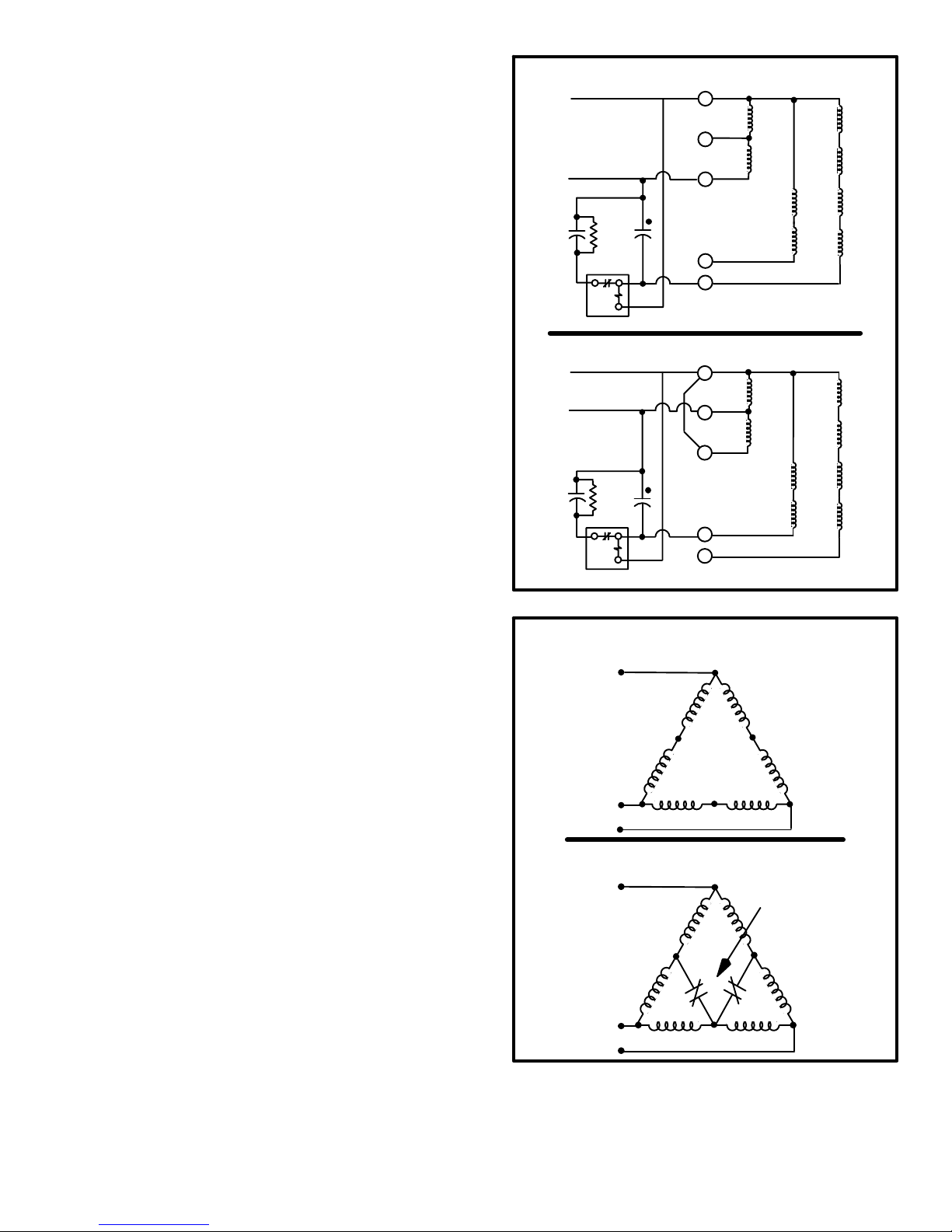
B−Operation Sequence − Compressor
Single-Phase Compressor Startup
Figure 26 shows single-phase compressor windings. This
compressor has a two speed capacitor-start, capacitor-run
motor. For starting, the start and run capacitors are in parallel to provide the proper starting torque. The start
capacitor is disconnected by the start relay when the compressor comes up to speed. The run capacitor remains
connected to the start winding and the motor runs as a twophase induction motor with improved power factor and
torque characteristics provided by the capacitor.
Low speed compressor operation is provided by powering
the run windings (internally connected in series) from terminals 1 (common) and 7. The windings form a four-pole
motor operating at 1800 RPM. The four low speed start
windings are in series and are connected to terminals 1
(common) and 8. They are used with the start and run capacitors and start relay to start and bring the motor up to
speed.
High speed compressor operation is provided when the run
windings are connected in parallel; terminals 1 (common)
and 7 to L1 and terminal 2 to L2. The windings form a twopole motor operating at 3600 RPM. The two high speed
start windings are in series and connected to terminals 1
(common) and 3.
Three Phase Compressor Startup
Figure 27 shows the windings of three-phase two-speed
compressors. The compressors have two-speed, threephase induction motors. Capacitors are not needed to
provide the proper phase and torque characteristics.
Low speed operation is provided when the motor windings
are connected in a series Delta" circuit. The motor operates at 1800 RPM.
High speed operation is provided when the motor windings
are connected in a parallel Delta" circuit. Normally closed
contacts on the low speed contactor provide this connection.
SINGLE-PHASE MOTOR WINDINGS LOW SPEED
START
CAP.
MOTOR LEAD TERMINALS
RUN
CAP.
START RELAY
1
COMMON
2
7
RUN WINDINGS
HIGH SPEED
START WINDINGS
3
8
LOW SPEED
START WINDINGS
SINGLE-PHASE MOTOR WINDINGS HIGH SPEED
START
CAP.
MOTOR LEAD TERMINALS
RUN
CAP.
START RELAY
1
COMMON
2
7
RUN WINDINGS
HIGH SPEED
START WINDINGS
3
8
START WINDINGS
LOW SPEED
FIGURE 26
THREE-PHASE MOTOR WINDINGS LOW SPEED
SERIES DELTA" CIRCUIT
L1
L2
T2
L3
T1
T6
T5
T4
T3
THREE-PHASE MOTOR WINDINGS HIGH SPEED
PARALLEL DELTA" CIRCUIT
L1
T4
COMPRESSOR
CONTACTOR K1−1
Page 29
T1
L2
L3
T3
T5T2T6
FIGURE 27

3
4
5
2
1
FIGURE 28
C−SINGLE-PHASE STARTING SEQUENCE
1− Line voltage feeds through L1 and L2 to energize outdoor transformer
T19 and outdoor unit. Crankcase heater is energized through relay K1
auxiliary contacts.
2− Transformer T19 provides 24VAC to TSC and contactors K1 and K69.
3− The indoor transformer supplies 24VAC to the indoor unit and the in-
door thermostat. Indoor transformer also provides 24VAC power to
defrost control CMC1, reversing valve L1, speed control thermostat
S55, service light thermostat S54 and ambient thermistor RT3 in outdoor unit.
4− On power-up, 24VAC is fed through JP44-1 and JP44-7 to the TSC.
The TSC begins a 10 second power-up delay.
5− The TSC begins a 5 minute delay during which the outdoor unit is not
operational. After the 5 minute delay, the TSC waits in OFF" mode for
1st stage or 2nd stage demand.
Page 30

10
D−SINGLE-PHASE COMPRESSOR STARTUP
LOW SPEED
1− 1st stage demand: If all safety circuits check out, TSC energizes
JP44-9.
2− Contactor K1 is energized through K69-2 N.C. contacts. K1-2 contacts
open to de−energize the crankcase heater. All other K1 contacts close
to start outdoor fan operation and to begin compressor low speed startup.
3− Compressor B1 terminal 1 and the outdoor fan circuit are energized by
K1 contacts L1-T1. Compressor terminal 7 is energized by contactor
K1 terminal L2-T2 through contactor K69 terminal T1-X1. Compressor
terminal 8 (start winding) is energized by contactor K1 terminal L2-T2
through the start (C7) and run (C5) capacitors and contactor K69 terminal T3-X3.
6
1
7
2
3
4
9
8
5
4−Outdoor fan B4 is energized through relay K4-2 when contactor K1
contacts L1-T1 and L2-T2 close.
5− As the compressor nears full speed, potential relay K31 energizes and
K31 contacts open to de-energize the start capacitor.
HIGH SPEED
6− 2nd stage demand: If all safety circuits check out, TSC energizes
JP44-8.
7− Contactor K69 energizes and K69-2 auxiliary contacts close to ener-
gize contactor K1. K1-2 auxiliary contacts open to de-energize the
crankcase heater. All other K1 contacts close. K1 contacts L1-T1,
L2-T2 and L3-T3 close while contacts T1-X1 and T3-X3 open.
8− Compressor B1 terminal 3 (start winding) is energized by contactor K1
terminal L2-T2 through the start (C7) and the run (C5) capacitors and
through contactor K69 terminal L3-T3. Compressor terminal 2 is energized by contactor K1 terminal L2-T2. Compressor terminal 1 is
energized directly by contactor K1 terminal L1-T1. Compressor terminal 7 is energized by contactor K1 terminal L1-T1 through contactor
K69 terminal L1-T1.
9−Outdoor fan B4 is energized through relay K4-2 when contactor K1
contacts L1-T1 and L2-T2 close.
10− As the compressor nears full speed, potential relay K31 energizes and
K31 contacts open to de-energize start capacitor C7.
FIGURE 29
Page 31

2 6 9
7
3
1
5
1
4
8
FIGURE 30
E−SINGLE-PHASE COOLING SEQUENCE
1− 1st stage cooling demand energizes TB15-Y1 and TB15-O. TB15-O
energizes reversing valve L1. TB15-Y1 energizes TSC terminal
JP44-6 and defrost control terminal HOLD. Defrost control begins initial timing sequence.
NOTE-2nd stage cooling demand may be energized directly without
passing through 1st stage.
2− TSC delays 3 seconds before responding to the new command.
3− If the unit is changing from 2nd stage to 1st stage demand, TSC initi-
ates speed change delay and de-energizes JP44-8 and JP44-9 to stop
all unit operation for 60+5 seconds. After TSC completes the 60+5 second speed change delay or if the unit is starting-up in 1st stage directly
from OFF mode, TSC checks safety circuits by looking for 24VAC at
JP44-7 and by checking resistance through wires connected to S1 and
S2.
4− If all safety circuits check-out, TSC energizes K1 and compressor be-
gins low speed startup.
5− 2nd stage cooling demand energizes TB15-Y1, TB15-Y2 and TB15-O.
TB15-O energizes TSC terminal JP44-4. TB15-O energizes TSC terminal JP44-6 and defrost control terminal HOLD.
6− TSC delays 3 seconds before responding.
7− If the unit is changing from 1st stage to 2nd stage demand, the TSC
initiates speed change delay and de-energizes JP44-8 and JP44-9 to
stop all unit operation for 60+5 seconds. After TSC completes the 60+5
second speed change delay or if the unit is starting-up in 2nd stage directly from OFF mode, TSC checks safety circuits by looking for
24VAC at JP44-7 and by checking resistance through wires connected
to S1 and S2.
8− If all safety circuits check-out, TSC energizes K1 and K69. Compres-
sor begins high speed startup.
9− When thermostat demand is satisfied or if thermostat is switched OFF
or switched to heating mode, all outdoor unit operation stops after a
delay of 3 seconds. TSC then completely resets (erase accumulated
faults) before beginning a 5 minute timed-off delay.
Page 32

3
4
1
5
2
FIGURE 31
F−SINGLE-PHASE HEATING SEQUENCE
1− Speed control thermostat S55 determines whether the compressor is
to operate on high or low speed based on outdoor temperature. If outdoor temperature drops below set temperature, S55 closes to shunt
across Y2. When Y2 is shunted, a 2nd stage demand is sent to the two
speed control and the compressor runs on high speed. If outdoor temperature rises above set temperature, S55 opens and the compressor
runs on low speed.
2− 1st stage demand energizes TB15-Y1. TB15-Y1 energizes TSC,
speed control thermostat S55 and defrost control terminal HOLD. Defrost control initializes timing sequence.
NOTE-2nd stage heating demand may be energized directly without
passing through 1st stage.
3− TSC delays 3 seconds before responding to the new command. Then
compressor begins operating at low or high speed as determined by
speed control thermostat S55.
4− 2nd stage heating demand energizes TB15-Y1 and TB15-W1.
TB15-Y1 energizes TSC, speed control thermostat S55 and defrost
control terminal HOLD. The compressor continues to operate at low or
high speed as determined by speed control thermostat S55. TB15- W1
energizes the indoor auxiliary heat relay for 2nd stage heat.
5− Speed control thermostat can open or close during 1st stage or 2nd
stage heating operation. When S55 opens, the compressor runs on
low speed. When S55 closes, the compressor runs on high speed. If
speed control thermostat S55 opens or closes during compressor operation, TSC initiates speed change delay and stops all unit operation
for 60+5 seconds (indoor unit continues to operate and if 2nd stage
thermostat demand is present auxiliary heat continues operate). If all
safety circuits check-out, TSC energizes compressor.
Page 33

4
2
1
3
2
FIGURE 32
G−SINGLE-PHASE DEFROST SEQUENCE
1− When the defrost control determines a defrost needs to be initiated it
closes an internal relay connected to DEF RLY terminal. Relay K4 is
energized. Relay K4 controls defrost.
2− When relay K4 energizes, K4-1 switches to energize the reversing
valve, K4-2 opens to de-energize the outdoor fan and K4-3 closes to
energize auxiliary heat.
3− Refer to the unit component section of this manual for detailed defrost
control operation. Defrost is terminated when relay K4 is de-energized.
Thermostat Demand Satisfied
4− When thermostat demand is satisfied or if thermostat is switched OFF
or switched to heating mode, all outdoor unit operation stops after a
delay of 3 seconds. TSC then completely resets (erase accumulated
faults) before cycling through the 5 minute timed-off delay.
Page 34

2
4
5
3
1
FIGURE 33
H−THREE-PHASE STARTING SEQUENCE
1− Line voltage feeds through L1, L2 and L3 to energize outdoor trans-
former T19 and outdoor unit. Crankcase heater is energized through
relay K10-1 outdoor fan contacts.
2− Transformer T19 provides 24VAC to TSC and contactors K1 and K69.
3− The indoor transformer supplies 24VAC to the indoor unit and the in-
door thermostat. Indoor transformer also provides 24VAC power to
S1, S2 DENOTE
TERMINAL
DESIGNATIONS
defrost control CMC1, reversing valve L1, outdoor fan relay K10,
speed control thermostat S55, service light thermostat S54 and ambient thermistor RT3 in outdoor unit.
4− On power-up, 24VAC is fed through JP44-1 and JP44-7 to the TSC.
The TSC begins a 10 second power-up delay.
5− The TSC begins a 5 minute delay during which the outdoor unit is not
operational. After the 5 minute delay, the TSC waits in OFF" mode for
1st stage or 2nd stage demand.
Page 35

I−THREE-PHASE COMPRESSOR STARTUP
LOW SPEED
1− Low speed demand energizes outdoor fan relay K10 and JP44−6.
K10-1 switches to energize the outdoor fan and de-energize the crankcase heater. Outdoor fan begins operating immediately.
2− After appropriate time delay and if all safety circuits check out, TSC
energizes JP44-9. Contactor K1 is energized through K69-2 N.C. contacts.
3− K1 N.O. contacts close to begin compressor low speed startup. K1
5
1
6
2
3
7
N.C. contacts open to disconnect the high speed wiring circuitry.
4− Compressor B1 terminal 1 is energized by K1 contacts L1-T1. Com-
pressor terminal 2 is energized by contactor K1 terminal L2-T2.
Compressor terminal 3 is energized by contactor K1 terminal L3-T3.
This arrangement forms a series DELTA connection to the motor windings for low speed.
HIGH SPEED
5− High speed demand energizes JP44-4.
6− After appropriate time delay and if all safety circuits check out, TSC en-
ergizes JP44-8.
7− When contactor K1 is de-energized, contacts K1-1 normally closed
contacts form a parallel DELTA connection to the motor windings for
high speed.
8− Contactor K69 energizes through K1-2 N.C. contacts (speed change
delay has reset K1-2 to N.C. position). N.O. K69-1 contacts close to begin compressor high speed startup. Compressor terminal 4 is
energized by contactor K69 terminal L1-T1. Compressor terminal 6 is
energized by contactor K69 terminal L2-T2. Compressor terminal 5 is
energized by contactor K69 terminal L3-T3.
8
1
4
FIGURE 34
Page 36

4
9
3
8
11
1
6
1
5
10
S1, S2 DENOTE
TERMINAL DES-
IGNATIONS
2
7
FIGURE 35
J−THREE-PHASE COOLING SEQUENCE
1− 1st stage cooling demand energizes TB15-Y1 and TB15-O. TB15-O
energizes reversing valve L1. TB15-Y1 energizes TSC terminal
JP44-6, relay K10 and defrost control terminal HOLD. Defrost control
monitors liquid line temperature and turns off defrost control when liq-
uid line rises above 65°F.
NOTE-2nd stage cooling demand may be energized directly without
passing through 1st stage.
2− Relay contacts K10-1 switch to energize the outdoor fan and to de-en-
ergize the crankcase heater.
3− TSC delays 3 seconds before responding to the new command.
4− If the unit is changing from 2nd stage to 1st stage demand, TSC initi-
ates speed change delay and de-energizes JP44-8 and JP44-9 to stop
all unit operation for 60+5 seconds. Outdoor fan continues to operate.
After TSC completes the 60+5 second speed change delay or if the unit
is starting-up in 1st stage directly from OFF mode, TSC checks safety
circuits by looking for 24VAC at JP44-7 and by checking resistance
through wires connected to S1 and S2.
5− If all safety circuits check-out, TSC energizes K1 and compressor be-
gins low speed startup.
6− 2nd stage cooling demand energizes TB15-Y1, TB15-Y2 and TB15-O.
TB15-Y2 energizes TSC terminal JP44-4. TB15-Y1 energizes TSC
terminal JP44-6, defrost control terminal HOLD and outdoor fan relay
K10.
7− Relay contacts K10-1 switch to energize the outdoor fan and to de-en-
ergize the crankcase heater.
8− TSC delays 3 seconds before responding.
9− If the unit is changing from 1st stage to 2nd stage demand, the TSC
initiates speed change delay and de-energizes JP44-8 and JP44-9 to
stop all unit operation for 60+5 seconds. After TSC completes the 60+5
second speed change delay or if the unit is starting-up in 2nd stage directly from OFF mode, TSC checks safety circuits by looking for
24VAC at JP44-7 and by checking resistance through wires connected
to S1 and S2.
10− If all safety circuits check-out, TSC energizes K69. Compressor be-
gins high speed startup.
11− When thermostat demand is satisfied or if thermostat is switched OFF
or switched to heating mode, all outdoor unit operation stops after a
delay of 3 seconds. TSC then completely resets (erase accumulated
faults) before beginning a 5 minute timed-off delay.
Page 37

3
4
1
5
2
S1, S2 DENOTE
TERMINAL
DESIGNATIONS
FIGURE 36
K−THREE-PHASE HEATING SEQUENCE
1− Speed control thermostat S55 determines whether the compressor is
to operate on high or low speed based on outdoor temperature. If outdoor temperature drops below set temperature, S55 closes to shunt
across Y2. When Y2 is shunted, a 2nd stage demand is sent to the twospeed control and the compressor runs on high speed. If outdoor
temperature rises above set temperature, S55 opens and the compressor runs on low speed.
2− 1st stage demand energizes TB15-Y1. TB15-Y1 energizes TSC,
speed control thermostat S55 and defrost control terminal HOLD. Defrost control initializes timing sequence.
NOTE-2nd stage heating demand may be energized directly without
passing through 1st stage.
3− TSC delays 3 seconds before responding to the new command. Then
compressor begins operating at low or high speed as determined by
speed control thermostat S55.
4− 2nd stage heating demand energizes TB15-Y1 and TB15-W1.
TB15-Y1 energizes TSC, speed control thermostat S55 and defrost
control terminal HOLD. The compressor continues to operate at low or
high speed as determined by speed control thermostat S55. TB15- W1
energizes the indoor auxiliary heat relay for 2nd stage heat.
5− Speed control thermostat can open or close during 1st stage or 2nd
stage heating operation. When S55 opens, the compressor runs on
low speed. When S55 closes, the compressor runs on high speed. If
speed control thermostat S55 opens or closes during compressor operation, TSC initiates speed change delay and stops all unit operation
for 60+5 seconds (indoor unit continues to operate and if 2nd stage
thermostat demand is present auxiliary heat continues operate). If all
safety circuits check-out, TSC energizes compressor.
Page 38

4
2
3
1
S1, S2 DENOTE
TERMINAL
DESIGNATIONS
FIGURE 37
L−THREE-PHASE DEFROST SEQUENCE
1− When the defrost control determines a defrost needs to be initiated it
closes an internal relay connected to DEF RLY terminal. Relay K4 is
energized. Relay K4 controls defrost.
2− When relay K4 energizes, K4-1 switches to energize the reversing
valve, K4-2 opens to de-energize the outdoor fan and K4-3 closes to
energize auxiliary heat.
3− Refer to the unit component section of this manual for detailed defrost
control operation. Defrost is terminated when relay K4 is de-energized.
Thermostat Demand Satisfied
4− When thermostat demand is satisfied or if thermostat is switched OFF
or switched to heating mode, all outdoor unit operation stops after a
delay of 3 seconds. TSC then completely resets (erase accumulated
faults) before cycling through the 5 minute timed-off delay.
Page 39

Page 40
HP21-2/-3 Wiring (Single Phase Units Shown)

Page 41
HP21-2/-3 Wiring (Three Phase Units Shown)

Page 42
HP21-4/-5 Wiring (Single Phase Units Shown)

Page 43
HP21-4/-5 Wiring (Three Phase Units Shown)

Page 44
HP21-36−230/60−230 Wiring

Page 45
HP21-36−233/60−233 Wiring

HP21−36−230 / 60−230−3 UNITS
SINGLE PHASE
Page 46

HP21−36−230 / 60−230−3 UNITS
OPERATION SEQUENCE
SINGLE-PHASE COOLING SEQUENCE
The TSC two−speed control has an external temperature probe
to lockout low speed during low temperatures, plus a potentiometer used for setting the low speed lock out temperature.
The adjustment range is 38° to 55°. This lockout will occur in
heating and cooling mode.
1− 1st stage cooling demand energizes TB15-Y1 and TB15-O.
TB15-O sends signal to O on defrost board which energizes
reversing valve L1. TB15-Y1 energizes TSC terminal
JP44-6.
NOTE-2nd stage cooling demand may be energized directly without passing through 1st stage.
2− TSC delays 3 seconds before responding to the new com-
mand.
3− If the unit is changing from 2nd stage to 1st stage demand,
TSC initiates speed change delay and de-energizes JP44-8
and JP44-9 to stop all unit operation for 60+5 seconds. After
TSC completes the 60+5 second speed change delay or if
the unit is starting-up in 1st stage directly from OFF mode,
TSC checks safety circuits by looking for 24VAC at JP44-7
and by checking resistance through wires connected to S1
and S2.
4− If all safety circuits check-out, TSC energizes K1 and com-
pressor begins low speed startup.
5− 2nd stage cooling demand energizes TB15-Y1, TB15-Y2
and TB15-O. TB15-Y2 energizes TSC terminal JP44-4.
TB15-Y1 energizes TSC terminal JP44-6.
6− TSC delays 3 seconds before responding.
7− If the unit is changing from 1st stage to 2nd stage demand,
the TSC initiates speed change delay and de-energizes
JP44-8 and JP44-9 to stop all unit operation for 60+5 seconds. After TSC completes the 60+5 second speed change
delay or if the unit is starting-up in 2nd stage directly from
OFF mode, TSC checks safety circuits by looking for 24VAC
at JP44-7 and by checking resistance through wires connected to S1 and S2.
8− If all safety circuits check-out, TSC energizes K1 and K69.
Compressor begins high speed startup.
9− When thermostat demand is satisfied or if thermostat is
switched OFF or switched to heating mode, all outdoor unit
operation stops after a delay of 3 seconds. TSC then completely resets (erase accumulated faults) before beginning a
5 minute timed-off delay.
SINGLE-PHASE HEATING SEQUENCE
10−1st stage demand energizes TB15-Y1. TB15-Y1 energizes
TSC, and defrost control. Defrost control initializes timing
sequence.
NOTE-2nd stage heating demand may be energized directly without passing through 1st stage.
11− TSC delays 3 seconds before responding to the new com-
mand. Then compressor begins operating at low or high
speed depending on the outdoor ambient.
12− 2nd stage heating demand energizes TB15-Y1 and
TB15-W1. TB15-Y1 energizes TSC. The compressor continues to operate at low or high speed as determined by the
outdoor ambient. W1 energizes the indoor auxiliary heat
relay for 2nd stage heat.
DEFROST SEQUENCE
Upon initial power up or first heating demand after cooling
mode, a sacrificial" defrost operation will occur in order to calibrate the board. Calibration will occur after accumulated compressor run time of 34 minutes and coil temperature is below
35°.
13− Y1 is energized in HEAT mode, de−energizing reversing
valve.
14− Compressor run time of 34 minutes accumulated. Defrost
begins. N.C. FAN terminal on board remains open, allowing
fan to cycle during defrost.
15− Defrost will last a maximum of 14 minutes or until the coil
temperature sensed at the coil probe exceeds the selected
pin termination temperature. Pin values are 50°, 60° 70° and
80°. (Factory setting is 70°).
Page 47

HP21−36−230 / 60−230−3 UNITS
THREE PHASE
Page 48

HP21−36−230 / 60−230−3 UNITS
OPERATION SEQUENCE
THREE−PHASE COOLING SEQUENCE
The TSC two−speed control has an external temperature probe
to lockout low speed during low temperatures, plus a potentiometer used for setting the low speed lock out temperature.
The adjustment range is 38° to 55°. This lockout will occur in
heating and cooling mode.
1− 1st stage cooling demand energizes TB15-Y1 and TB15-O.
TB15-O sends signal to O on defrost board which energizes
reversing valve L1. TB15-Y1 energizes TSC terminal
JP44-6.
NOTE-2nd stage cooling demand may be energized directly without passing through 1st stage.
2− TSC delays 3 seconds before responding to the new com-
mand.
3− If the unit is changing from 2nd stage to 1st stage demand,
TSC initiates speed change delay and de-energizes JP44-8
and JP44-9 to stop all unit operation for 60+5 seconds. After
TSC completes the 60+5 second speed change delay or if
the unit is starting-up in 1st stage directly from OFF mode,
TSC checks safety circuits by looking for 24VAC at JP44-7
and by checking resistance through wires connected to S1
and S2.
4− If all safety circuits check-out, TSC energizes K1 and com-
pressor begins low speed startup.
5− 2nd stage cooling demand energizes TB15-Y1, TB15-Y2
and TB15-O. TB15-Y2 energizes TSC terminal JP44-4.
TB15-Y1 energizes TSC terminal JP44-6.
6− TSC delays 3 seconds before responding.
7− If the unit is changing from 1st stage to 2nd stage demand,
the TSC initiates speed change delay and de-energizes
JP44-8 and JP44-9 to stop all unit operation for 60+5 seconds. After TSC completes the 60+5 second speed change
delay or if the unit is starting-up in 2nd stage directly from
OFF mode, TSC checks safety circuits by looking for 24VAC
at JP44-7 and by checking resistance through wires connected to S1 and S2.
8− If all safety circuits check-out, TSC energizes K1 and K69.
Compressor begins high speed startup.
9− When thermostat demand is satisfied or if thermostat is
switched OFF or switched to heating mode, all outdoor unit
operation stops after a delay of 3 seconds. TSC then completely resets (erase accumulated faults) before beginning a
5 minute timed-off delay.
THREE−PHASE HEATING SEQUENCE
10−1st stage demand energizes TB15-Y1. TB15-Y1 energizes
TSC, and defrost control. Defrost control initializes timing
sequence.
NOTE-2nd stage heating demand may be energized directly without passing through 1st stage.
11− TSC delays 3 seconds before responding to the new com-
mand. Then compressor begins operating at low or high
speed depending on the outdoor ambient.
12− 2nd stage heating demand energizes TB15-Y1 and
TB15-W1. TB15-Y1 energizes TSC. The compressor continues to operate at low or high speed as determined by the
outdoor ambient. W1 energizes the indoor auxiliary heat
relay for 2nd stage heat.
DEFROST SEQUENCE
Upon initial power up or first heating demand after cooling
mode, a sacrificial" defrost operation will occur in order to calibrate the board. Calibration will occur after accumulated compressor run time of 34 minutes and coil temperature is below
35°.
13− Y1 is energized in HEAT mode, de−energizing reversing
valve.
14− Compressor run time of 34 minutes accumulated. Defrost
begins. N.C. outdoor fan relay K10 remains open, allowing
fan to cycle during defrost.
15− Defrost will last a maximum of 14 minutes or until the coil
temperature sensed at the coil probe exceeds the selected
pin termination temperature. Pin values are 50°, 60° 70° and
80°. (Factory setting is 70°).
Page 49

VIII−TROUBLESHOOTING FLOWCHARTS
The following flowcharts show how to diagnose problems
in two-speed heat pumps equipped with TSC control.
Table 19 shows how to determine if the TSC is functioning.
Tables 20a and 20b show how to correlate TSC diagnostics
to the unit.
Follow the flowcharts step by step. Disconnect as few
TABLE 19
TWO-SPEED CONTROL
TROUBLESHOOTING FLOWCHART
UNIT WILL NOT RUN
IS DIAGNOSTIC LED
LIT?
NO YES
CHECK VOLTAGE ACROSS COMPRESSOR CONTACTOR COILS. IS THERE 24
VAC ACROSS HIGH-SPEED CONTACTOR
COIL?
YES
LOW-SPEED
CONTACTOR IS
FAULTY.
TURN OFF UNIT POWER AT DISCONNECT FOR AT
LEAST 3 SECONDS. TURN POWER ON AND ALLOW
3 SECONDS FOR CONTROL TO POWER-UP.
NO
THREE-
PHASE
SINGLE-
PHASE
IS THERE 24 VAC
ACROSS LOWSPEED CONTACTOR
COIL?
NOYESHIGH−SPEED OR
CONTROL MAY BE
LOCKED OUT. BREAK
AND REMAKE THERMOSTAT DEMAND. DOES
COMPRESSOR START?
NO YES
NO
IS THERE 24 VAC
ACROSS LOW-SPEED
CONTACTOR COIL?
NO
YES
NORMAL LOCKOUT
wires as possible. Any time a repair is made, reassemble
the unit and retest for operation. If the unit does not operate, recheck up to that point and then continue through the
chart. Occasionally more than one specific problem may
exist. Do as little disassembly as possible and double
check your diagnosis before replacing components.
Be sure to remove all jumper wires and replace all wire connections and access panels before placing unit back in
service.
NOTE−Before beginning this troubleshooting procedure make sure that 1) primary side of contactor
is supplied with line voltage 2)indoor and outdoor
transformers are delivering 24vac and 3)line voltage is supplied to compressor terminals when
contactors engage.
CONTROL MAY BE LOCKED OUT. TURN
POWER OFF AT DISCONNECT FOR 3 SEC.
IS DIAGNOSTIC LED STILL LIT?
YES
IS THERE 24 VAC
ACROSS LOWSPEED CONTACTOR
COIL?
NO YES
HIGH-SPEED AUXILIARY
SWITCH IS NOT MAKING
PROPERLY. REPLACE
CONTACTOR.
CONTROL WAS LOCKED OUT DUE TO UNIT PROBLEMS. CONTINUE THROUGH TROUBLESHOOTING FLOWCHART IN THE UNIT INFORMATION
MANUAL TO LOCATE REASON FOR LOCKOUT.
REPLACE
CONTROL
HIGH−SPEED OR LOW-
SPEED CONTACTOR
IS FAULTY.
NOYES
APPLY THERMOSTAT DEMAND.
CHECK UNIT VOLTAGE AND
MANUALLY RESET CONTROLS.
TRY TO START COMPRESSOR
BY PRESSING AND RELEASING
MANUAL OVERRIDE BUTTON.
DOES COMPRESSOR
START?
NO YES
CONTROL IS PROBABLY GOOD
AND THE PROBLEM IS LOCATED
ELSEWHERE IN THE UNIT. PROCEED THROUGH TROUBLESHOOTING FLOWCHART IN THE
UNIT INFORMATION MANUAL TO
LOCATE THE PROBLEM. START
BY CHECKING ALL MANUALLY
RESET CONTROLS.
Page 50
SAFETY DORMANT LOCKOUT
CONTROL IS NOW OUT OF SAFETY DORMANT LOCKOUT AND HAS
RESUMED NORMAL OPERATION.
DO NOT REPLACE CONTROL..
SAFETY DORMANT LOCKOUT
WAS PROBABLY CAUSED BY A
SELF-TEST FAILURE OR LINE
VOLTAGE SPIKE.

TABLE 20a
HP21 UNIT CONTROLS DIAGNOSTICS
START
HERE
CHECK SUPPLY VOLTAGE. IS SUPPLY VOLTAGE
WITHIN RANGE SHOWN ON UNIT RATING PLATE?
CORRECT POWER SUPPLY.
MANUALLY RESET HIGH PRESSURE SWITCH S4
IN OUTDOOR UNIT IF TRIPPED.
NO
YES
HIGH SPEED COOLING
1− TURN INDOOR THERMOSTAT TO OFF POSITION.
2− SET INDOOR THERMOSTAT TO LOWEST TEMPERATURE SETTING.
3− TURN INDOOR THERMOSTAT TO COOL MODE.
4− IF POWER TO OUTDOOR UNIT HAS BEEN OFF, WAIT AT LEAST 10
SECONDS TO ALLOW TSC TO POWER-UP.
5− PUSH AND RELEASE THE OVERRIDE BUTTON ON THE TSC TO BY-
PASS THE 5-MINUTE TIMED-OFF DELAY.
6− ALLOW 1 MINUTE FOR THE UNIT TO START.
DOES UNIT START AND RUN ON HIGH SPEED?
YES NO
CHOOSE COOLING OR HEATING MODE
GO TO A
ON NEXT PAGE
IS UNIT IN COOLING MODE?
REVERSING VALVE SHOULD BE ENERGIZED.
REVERSING VALVE ENERGIZED/
YES NO
CHECK VOLTAGE ACROSS TERMINALS R AND X
AT UNIT LOW VOLTAGE TERMINAL STRIP TB15.
CHECK REVERSING VALVE
FOR MALFUNCTIONS.
REPLACE IF NECESSARY.
HIGH SPEED COOLING O.K.
LOW SPEED COOLING
1− TURN INDOOR THERMOSTAT TO OFF POSITION.
2− DISCONNECT THERMOSTAT WIRE FROM TERMINAL Y2 OF HEAT
PUMP LOW VOLTAGE TERMINAL STRIP TB15.
3− SET INDOOR THERMOSTAT TO LOWEST TEMPERATURE SETTING.
4− TURN INDOOR THERMOSTAT TO COOL MODE.
5− IF POWER TO OUTDOOR UNIT HAS BEEN OFF, WAIT AT LEAST 10
SECONDS TO ALLOW TSC TO POWER-UP.
6− PUSH AND RELEASE THE OVERRIDE BUTTON ON THE TSC TO BY-
PASS THE 5-MINUTE TIMED-OFF DELAY.
7− ALLOW 1 MINUTE FOR THE UNIT TO START.
DOES UNIT START AND RUN ON LOW SPEED?
YES NO
IS UNIT IN COOLING MODE?
REVERSING VALVE SHOULD BE ENERGIZED.
REVERSING VALVE ENERGIZED/
YES NO
LOW SPEED COOLING O.K.
IS VOLTAGE 24+
YES NO
REPEAT TROUBLESHOOTING
PROCEDURE.
6VAC?
CHECK INDOOR THERMOSTAT
FOR MALFUNCTIONS.
REPLACE IF NECESSARY.
GO TO B
ON NEXT PAGE
TSC OPERATING PROPERLY.
REASSEMBLE UNIT.
HIGH SPEED HEATING
1− TURN INDOOR THERMOSTAT TO OFF POSITION.
2− PLACE A JUMPER WIRE ACROSS SPEED CONTROL THERMOSTAT
S55 IN OUTDOOR UNIT.
3− SET INDOOR THERMOSTAT TO HIGHEST TEMPERATURE SETTING.
4− TURN INDOOR THERMOSTAT TO HEAT MODE.
5− IF POWER TO OUTDOOR UNIT HAS BEEN OFF, WAIT AT LEAST 10
SECONDS TO ALLOW TSC TO POWER-UP.
6− PUSH AND RELEASE THE OVERRIDE BUTTON ON THE TSC TO BY-
PASS THE 5-MINUTE TIMED-OFF DELAY.
7− ALLOW 1 MINUTE FOR THE UNIT TO START.
DOES UNIT START AND RUN ON HIGH
SPEED IN HEATING MODE?
GO TO A
ON NEXT PAGE
1− TURN INDOOR THERMOSTAT TO OFF POSITION.
2− REMOVE THE JUMPER WIRE FROM ACROSS SPEED CON-
TROL THERMOSTAT S55 IN OUTDOOR UNIT.
3− DISCONNECT THE FACTORY WIRING FROM EITHER SIDE
OF SPEED CONTROL THERMOSTAT S55.
4− SET INDOOR THERMOSTAT TO HIGHEST TEMPERATURE
SETTING.
5− TURN INDOOR THERMOSTAT TO HEAT MODE.
6− IF POWER TO OUTDOOR UNIT HAS BEEN OFF, WAIT AT
LEAST 10 SECONDS TO ALLOW TSC TO POWER-UP.
7− PUSH AND RELEASE THE OVERRIDE BUTTON ON THE TSC
TO BYPASS THE 5-MINUTE TIMED-OFF DELAY.
8− ALLOW 1 MINUTE FOR THE UNIT TO START.
DOES UNIT START AND RUN ON LOW
GO TO B
ON NEXT PAGE
YESNO
HIGH SPEED HEATING O.K.
LOW SPEED HEATING
SPEED IN HEATING MODE?
YESNO
LOW SPEED HEATING O.K.
TSC OPERATING PROPERLY.
REASSEMBLE UNIT.
CHECK VOLTAGE ACROSS TERMINALS O AND X
AT UNIT LOW VOLTAGE TERMINAL STRIP TB15.
CHECK REVERSING VALVE
FOR MALFUNCTIONS.
REPLACE IF NECESSARY.
IS VOLTAGE 24+
YES NO
REPEAT TROUBLESHOOTING PROCEDURE.
6VAC?
CHECK INDOOR THERMO-
STAT FOR MALFUNCTIONS.
REPLACE IF NECESSARY.
Page 51

TABLE 20b
CONTINUED FROM A ON PREVIOUS PAGE CONTINUED FROM B ON PREVIOUS PAGE
CHECK VOLTAGE ACROSS TERMINALS Y1 AND X
AND Y2 AND X AT UNIT LOW VOLTAGE TERMINAL
STRIP TB15. IS VOLTAGE 24+
CHECK INDOOR THERMOSTAT
FOR MALFUNCTIONS.
REPLACE IF NECESSARY.
REPEAT
TROUBLESHOOTING
PROCEDURE.
IS CONTACTOR(S) COIL
YES NO
ARE CONTACTS CLOSING?
YES
CHECK STARTING CIRCUIT
AND COMPRESSOR.
REPAIR OR REPLACE AS NECESSARY.
REPEAT
TROUBLESHOOTING
PROCEDURE.
1− TURN OFF POWER TO INDOOR AND OUT-
DOOR UNITS.
2− DISCONNECT TWO RED WIRES FROM
TERMINALS S1 AND S2 OF TSC.
3− CHECK THE COMPRESSOR INTERNAL
SENSORS BY CHECKING THE RESISTANCE (OHMS) THROUGH THE RED
WIRES.
CAUTION-THE RED WIRES (S1 AND S2)
MUST BE DISCONNECTED FROM THE TSC
FOR THIS TEST OR DAMAGE TO THE TSC
COULD RESULT.
IS RESISTANCE WITHIN RE-
SET RANGE LISTED ON UNIT
RATING PLATE?
YES NO
RECONNECT RED
WIRES (TO S1 AND S2)
AND RECONNECT JP44.
RED WIRES ARE NOT
POLARITY SENSITIVE.
CHECK INTERNAL WINDINGS
OF COMPRESSOR WITH
OHMMETER. ARE WINDINGS
OPEN OR SHORTED?
YESNO
REPLACE
TSC.
REPEAT TROUBLESHOOTING PROCEDURE.
CHECK VOLTAGE AT CONTACTOR COILS.
K1 AND K69 SHOULD BE ENERGIZED.
ENERGIZED?
NO
ALLOW COMPRESSOR
SUFFICIENT TIME TO
COOL TO RESET TEM-
PERATURE.
REPLACE
COMPRESSOR.
6VAC?
YESNO YES NO
FOR SINGLE PHASE UNITS,
FOR THREE PHASE UNITS,
K1 ONLY SHOULD BE ENERGIZED.
IS VOLTAGE 24+
YES NO
REPLACE CONTACTOR.
TROUBLESHOOTING
PROCEDURE.
CHECK VOLTAGE AT CONTACTOR COILS.
K69 ONLY SHOULD BE ENERGIZED.
6VAC?
CHECK SECONDARY (OUTPUT) VOLTAGE OF
THE TRANSFORMER IN THE OUTDOOR UNIT
REPEAT
CHECK PRIMARY (INPUT) VOLTAGE OF
THE TRANSFORMER IN THE OUTDOOR UNIT
IS MEASURED VOLTAGE SAME AS VOLTAGE
TRANSFORMER.
TROUBLESHOOTING PROCEDURE.
IS VOLTAGE 24+
IS FUSE PROVIDED IN TRANS-
FORMER SECONDARY?
TROUBLESHOOTING
ON UNITS RATING PLATE?
YES NO
REPLACE
REPEAT
RECONNECT RED WIRES (TO S1
AND S2) AND RECONNECT JP44.
RED WIRES ARE NOT POLARITY
SENSITIVE. REPEAT TROUBLE-
SHOOTING PROCEDURE.
VOLTAGE WIRING.
TROUBLESHOOTING
PROCEDURE.
CHECK VOLTAGE ACROSS TERMINALS Y1 AND X
AT UNIT LOW VOLTAGE TERMINAL STRIP TB15.
FOR SINGLE PHASE UNITS,
FOR THREE PHASE UNITS,
K1 ONLY SHOULD BE ENERGIZED.
IS VOLTAGE 24+
6VAC?
YESNO
YESNO
REPLACE
FUSE.
REPEAT
PROCEDURE.
1− TURN OFF POWER TO INDOOR AND OUTDOOR
UNITS.
2− DISCONNECT JACKPLUG JP44 FROM TSC.
3− TURN ON POWER TO OUTDOOR UNIT.
4− CHECK VOLTAGE ACROSS TERMINALS 2 AND
7 OF JACKPLUG JP44. IS VOLTAGE 24+
CHECK LINE
REPEAT
IS VOLTAGE 24+
6VAC?
YESNO
REPLACE CONTACTOR.
TROUBLESHOOTING
IS FUSE
O.K.?
CHECK VOLTAGE ACROSS
PINS 1 AND 2 OF JP44.
IS VOLTAGE 24+
PROCEDURE.
YESNO
NO
YES
YES
NO
CHECK WIRING
CONNECTIONS.
REPEAT
TROUBLESHOOTING
PROCEDURE.
6VAC?
CHECK INDOOR THERMOSTAT
FOR MALFUNCTIONS.
REPLACE IF NECESSARY.
TROUBLESHOOTING
PROCEDURE.
IS CONTACTOR(S) COIL
ENERGIZED?
REPEAT
6VAC?
CHECK SWITCHES S4 AND
S40 FOR MALFUNCTIONS.
REPLACE IF NECESSARY.
TROUBLESHOOTING
6VAC?
REPEAT
YESNO
ARE CONTACTS
CLOSING?
NO
YES
CHECK STARTING
CIRCUIT AND
COMPRESSOR.
REPAIR OR
REPLACE AS
NECESSARY.
REPEAT
TROUBLESHOOTING
PROCEDURE.
REPEAT
PROCEDURE.
Page 52

SERVICE NOTES
Page 53
 Loading...