

Page 1
INSTALLATION INSTRUCTIONS
®
G1N80BU, GIN80BR, GIN80BT, CG80UB, CG80RB, & CG80TB
80% Gas-Fired Furnace
WARNING
Improper installation, adjustment, alteration, service or maintenance can cause injury
or property damage. Refer to this manual. For assistance or additional information,
consult a qualified installer, service agency, or the gas supplier.
W ARNING
Do not store combustible materials, including
gasoline and other flammable vapors and
liquids, near the furnace, vent pipe, or warm
air ducts. The homeowner should be cautioned that the furnace area must not be
used as a broom closet or for any other
storage purposes. Such uses may result in
actions that could cause property damage,
personal injury, or death.
SAFETY ................................................. 2
INSTALLATION ...................................... 2
START-UP ............................................ 14
OPERATION ........................................ 15
MAINTENANCE................................... 16
T ABLE OF CONTENTS
CONTROL SYSTEM DIAGNOSTICS .. 18
W ARNING
REPAIR PARTS ................................... 18
This furnace is not approved for installation in
a mobile home. Do not install this furnace in a
WIRING DIAGRAMS ............................ 19
mobile home. Installation in a mobile home
could result in actions that could cause property damage, personal injury, or death.
A Lennox International Company
Manufactured By
A.A.C.
421 Monroe Street
Bellevue, OH 44811
®
IMPORT ANT
The installation of the furnace, wiring, warm air ducts, venting, etc. must conform to the requirements of the
National Fire Protection Association; the National Fuel Gas Code, ANSI Z223.1/NFPA No. 54 (latest edition)
and the National Electrical Code, ANSI/NFPA No. 70 (latest edition) in the United States; CSA B149.1
(latest edition) Natural Gas and Propane Installation Codes and the Canadian Electrical Code Part 1, CSA
22.1 (latest edition) in Canada; and any state or provincial laws, local ordinances (including plumbing or
wastewater codes), or local gas utility requirements. Local authorities having jurisdiction should be consulted before installation is made. Such applicable regulations or requirements take precedence over the
general instructions in this manual.
# 45464K003 Page 1
Page 2
IMPORT ANT SAFETY INFORMATION
The following is a list of safety rules and precautions
that must be followed when installing this furnace.
1. Use only with the type of gas approved for this
furnace. Refer to the furnace rating plate.
2. Install this furnace only in a location and position as
specified in the Location section on page 3 of
these instructions.
3. Provide adequate combustion and ventilation air to
the furnace space as specified in the Combustion
and Ventilation Air section beginning on page 4 of
these instructions.
4. Combustion products must be discharged outdoors.
Connect this furnace to an approved vent system
only, as specified in Venting beginning on page 6 of
these instructions.
5. Never test for gas leaks with an open flame. Use a
commercially available soap solution made specifically for the detection of leaks to check all connections, as specified in Gas Supply and Piping
beginning on page 12 of these instructions.
6. Always install furnace to operate within the furnace’s
intended temperature rise range with a duct system
which has an external static pressure within the
allowable range, as specified in Temperature Rise
on page 16 of these instructions. See furnace rating
plate.
7. When a furnace is installed so that the supply ducts
carry air circulated by the furnace to areas outside
the space containing the furnace, the return air shall
also be handled by duct(s) sealed to the furnace
casing and terminating outside the space containing
the furnace. See Circulating Air Supply on page 8
of these instructions.
8. A gas-fired furnace for installation in a residential
garage must be installed as specified in the Loca-
tion section on page 3 of these instructions.
9. The furnace is not to be used for temporary heating of
buildings or structures under construction as specified
on page 4 of these instructions.
In the State of Massachusetts:
This product must be installed by a licensed Plumber
or Gas Fitter. When flexible connectors are used, the
maximum length shall not exceed 36". When levertype gas shutoffs are used, they shall be T-handle
type.
INSTALLATION
These instructions must be placed on or near the
furnace in a conspicuous place.
This furnace is design certified by CSA International as a
Category I furnace using air from inside the structure for
combustion. The combustion system is fan-assisted, which
means it is equipped with an integral mechanical means to
draw products of combustion through the heat exchanger.
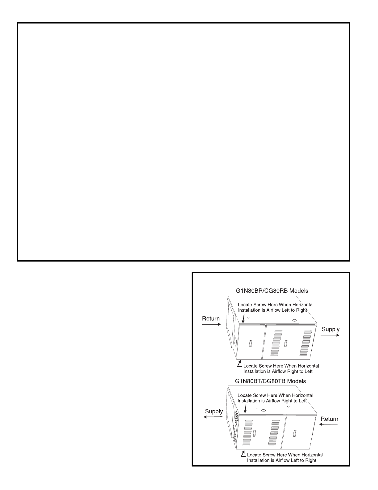
G1N80BT and CG80TB models may be installed as upflow
or horizontal furnaces. G1N80BR and CG80RB models
may be installed as counterflow (downflow) or horizontal
furnaces. When installed horizontally, the installer must
install a sheet metal screw to retain the upper door as
shown in Figure 1.
G1N80BU and CG80UB models must be installed only as
upflow furnaces.
Never install any furnace on its back.
Horizontal Installations
Figure 1
# 45464K003Page 2
Page 3
Inspection of Shipment
tenibaC
htdiW
sediS tnorF kcaB tneV
wolfriA
LotR RotL
poT mottoB poT mottoB
5.4108106
232
013
2
5.71 0 81 0 622
2
0 1 2
2
0.1208106210 10
5.42 0 81 0 621 0 1 0
tenibaC
htdiW
sediS tnorF kcaB tneV
wolfriA
LotR RotL
poT mottoB poT mottoB
5.411810621313
1
0
5.71 1 81 0 621 2
2
2
2
0
0.1218106210 10
This furnace is shipped in one package, completely
assembled and wired. The thermostat is shipped in a
separate carton when ordered.
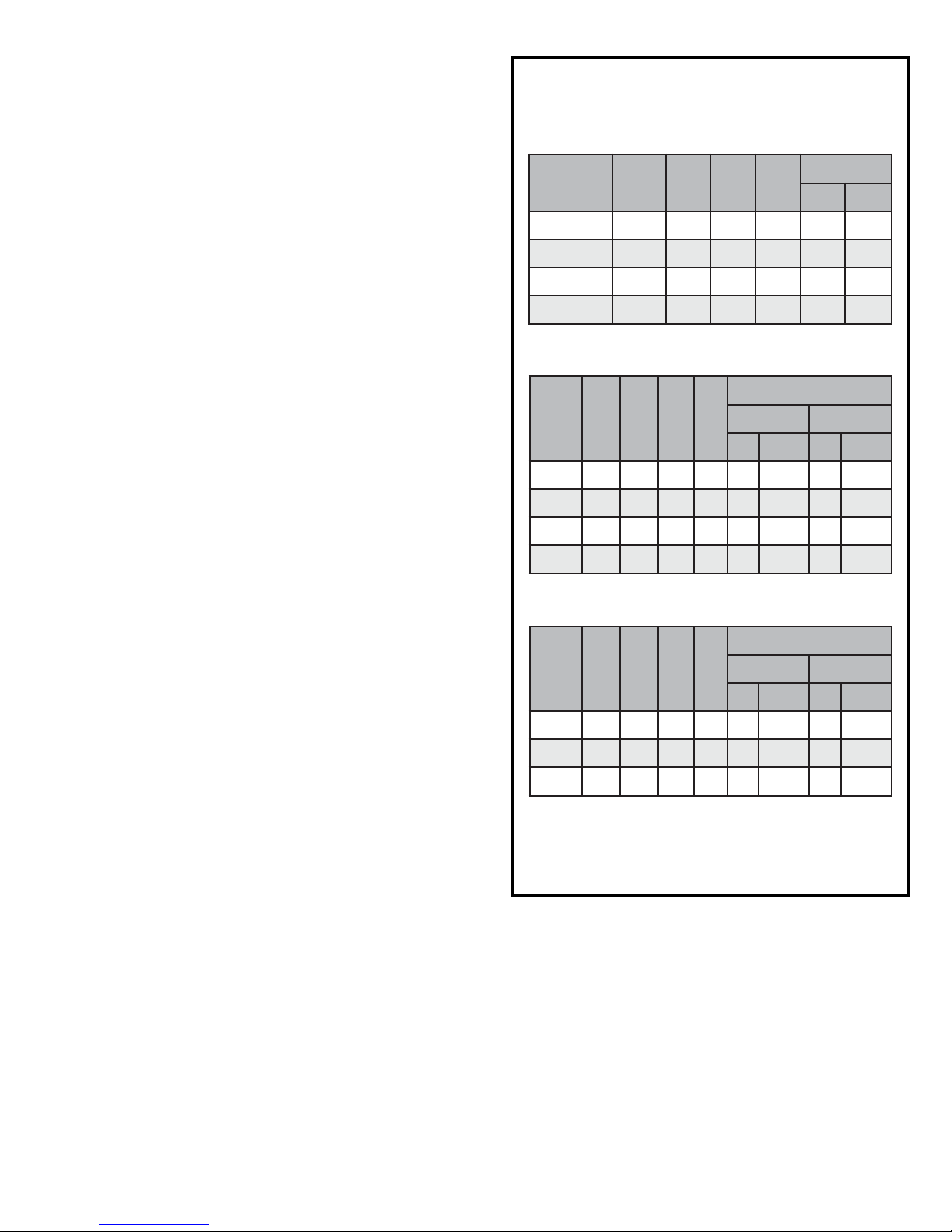
Minimum Clearances to Combustibles
(all measurements in inches)
Upflow and Counterflow Installations
Upon receipt of equipment, carefully inspect it for possible
shipping damage. If damage is found, it should be noted on
the carrier’s freight bill. Damage claims should be filed with
the carrier immediately. Claims of shortages should be
filed with the seller within 5 days.
Check the rating plate for correct model number, type of
gas, and input.
Clearances
All servicing and cleaning of the furnace can be performed
from the front. If installed in a closet or utility room, provide
18" clearance in front for service if the door to the room is
not in line with the front of the furnace.
All models are suitable for installation at reduced clearances to combustibles as noted in the tables in Figure 2.
Where servicing clearances are greater than clearances to
combustibles, servicing clearances take precedence.
G1N80BU, G1N80BT, CG80UB, and CG80TB models, and
horizontally installed G1N80BR and CG80RB models may
be installed on wood flooring, but shall not be installed
directly on carpeting, tile, or other combustible material
other than wood flooring.
tenibaC
htdiW
5.414
5.71 4
0.124
5.42 4
tnorF kcaB poT tneV
1
01623
1
0 1 6
1
016210
1
0 1 6
Horizontal Installations
(G1N80BR and CG80RB models)
Horizontal Installations
(G1N80BT and CG80TB models)
2
2
tfeL thgiR
3
3
2
0 0
sediS
0
0
G1N80BR and CG80RB models installed as counterflow
(downflow) units may be installed on combustible flooring
provided a special combustible floor base is used. Refer to
the Counterflow (Downflow) Installations section begin-
ning on page 10 for more information on using the special
base assembly.
Location
All models are suitable for closet or utility room installation.
The furnace must be installed so that electrical components are protected from water.
The furnace is suitable for installation in buildings constructed on-site. The furnace should be centralized in
respect to the heat distribution system as much as
practicable. When installed in a utility room, the door
should be wide enough to allow the largest part of the
furnace to enter, or permit the replacement of another
appliance, such as a water heater.
A gas-fired furnace for installation in a residential garage
must be installed so the burner(s) and the ignition source
are located not less than 18" above the floor. The furnace
is to be located or protected to avoid physical damage by
vehicles.
# 45464K003 Page 3
1
May be 2" when Type B-1 vent pipe is used.
2
May be 1" when Type B-1 vent pipe is used.
3
Where values greater than 0 are shown, may be 0"
when Type B-1 vent pipe is used.
Figure 2
G1N80BR, G1N80BT, CG80RB, and CG80TB models
installed in the horizontal position are approved for attic
installations. If the furnace is to be installed in an attic
or other insulated space, it must be kept free and
clear of insulating materials. When a furnace is
installed in conjunction with an evaporator coil in an
attic or above a finished ceiling where condensate
overflow could result in property damage, a drain
pan should be provided under the units as specified
by most local building codes.
Page 4
G1N80BR, G1N80BT, CG80RB, and CG80TB models may
be installed as suspended units in the horizontal position.
These furnaces are not designed for direct attachment of
suspension rods to the furnace casing.
However, in a building of unusually tight construction,
additional outdoor air should be provided.
Confined Space
The suspending means must be field fabricated, and
should consist of two “cradles” made by attaching two rods
to a length of angle iron or suitable gage steel. Locate the
cradles so that they are as close as possible to the ends
of the furnace (this will provide access for removal of
major components such as the blower assembly). Provide
enough clearance between the suspension rods and the
furnace to allow removal of access panels.
CAUTION
Do not use the furnace as a heater in a
building under construction. The furnace can
be severely damaged due to the abnormal
environment caused by construction. Chlorides from sources such as paint, stain, or
varnish; tile and counter cements; adhesives;
and foam insulation are abundant in a structure under construction and can be highly
corrosive. Low return air temperature can
cause condensation in the furnace and other
damage that can shorten the life of the unit.
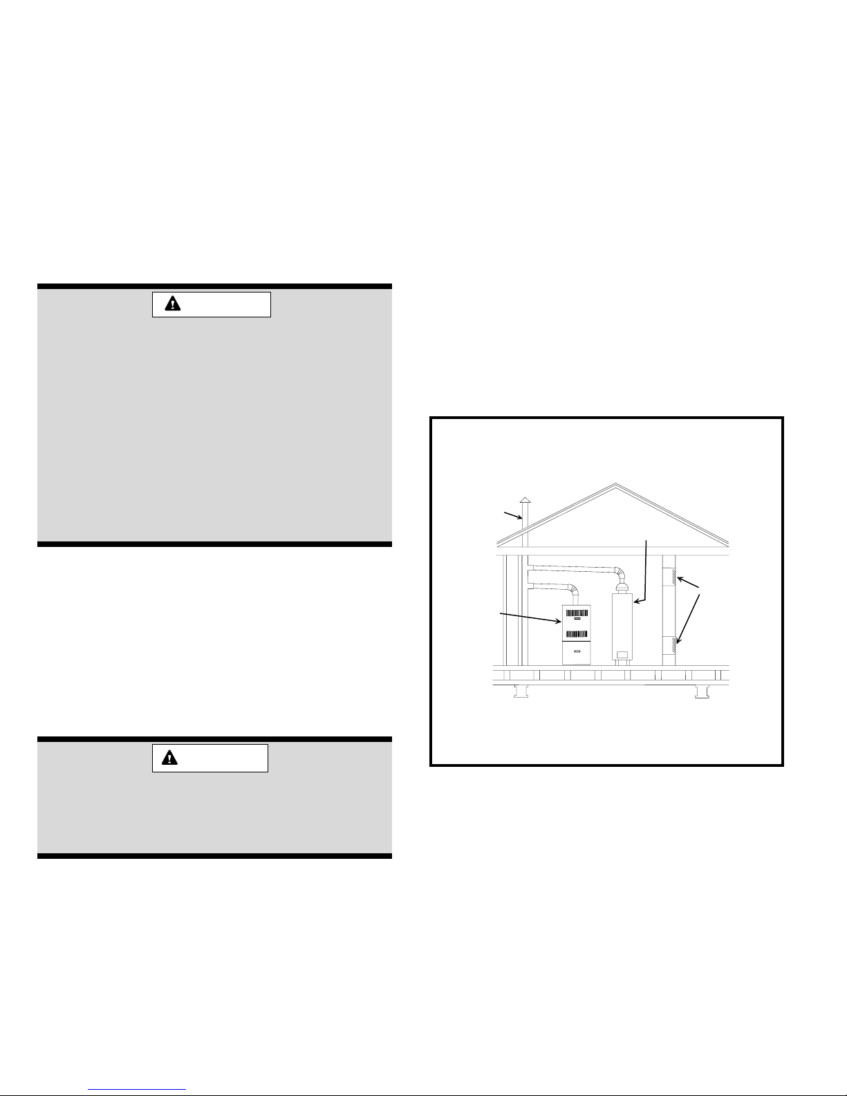
A confined space is defined as “a space whose volume is
less than 50 cubic feet per 1000 BTU per hour of the
combined input rating of all appliances installed in that
space.”
Confined Space Installation/Air from Inside Structure
If the furnace is installed in a confined space within the
building and combustion air is taken from a heated space,
the combustion air and ventilating air must enter and leave
the space through two permanent openings of equal area.
One opening shall be located within 12" of the ceiling and
the other within 12" of the floor, each having a free area of
1 square inch per 1000 BTU/HR of total input rating of all
appliances within the space and not less than 100 square
inches each (see Figure 3).
Equipment in Confined Space
All Air From Inside
Chimney or
Gas Vent
Water
Heater
Combustion and Ventilation Air
Adequate provisions for combustion air and ventilation of
furnace must be made. Refer to Section 5.3, “Air for
Combustion and Ventilation,” of the National Fuel Gas
Code, ANSI Z223.1/NFPA54 (latest edition), Sections 7.2,
7.3, or 7.4 of CSA B149.1 Natural Gas and Propane
Installation Codes (latest editions), or applicable provisions of the local building codes.
WARNING
Air openings in the front of the furnace must
be kept free of obstructions. Any obstruction
may cause improper operation that can result
in a fire hazard or carbon monoxide injury.
Unconfined Space
An unconfined space is defined as “a space whose volume
is more than 50 cubic feet per 1000 BTU per hour of the
combined input rating of all appliances installed in that
space.” When a furnace is installed in an unconfined space
in a building, it can be assumed that the infiltration will be
sufficient to supply the required air. If the furnace is
installed in a ventilated attic or crawl space, it is assumed
that the infiltration is sufficient to supply the required air.
Openings
Furnace
Note: Each opening shall have a free area of at least one square
inch per 1000 BTU per hour of the total input rating of all
equipment in the enclosure, but not less than 100 square
inches.
Figure 3
Confined Space Installation/Air from Outside Structure
If air from outside is brought in for combustion, the confined
space shall be provided with two permanent openings. One
opening shall be within 12" of the ceiling and one opening
within 12" of the floor. Several methods can be used to bring
the outside air in through these openings. The openings
shall open directly or by ducts with the outdoors, through
spaces (crawl space or attic) that freely open to the outdoors, or indirectly through vertical ducts (see Figures 4 and
5). If any of these methods are used, each opening shall
have a free area of 1 square inch per 4000 BTU/HR of the
total input rating of all appliances within the enclosure.
# 45464K003Page 4
Page 5
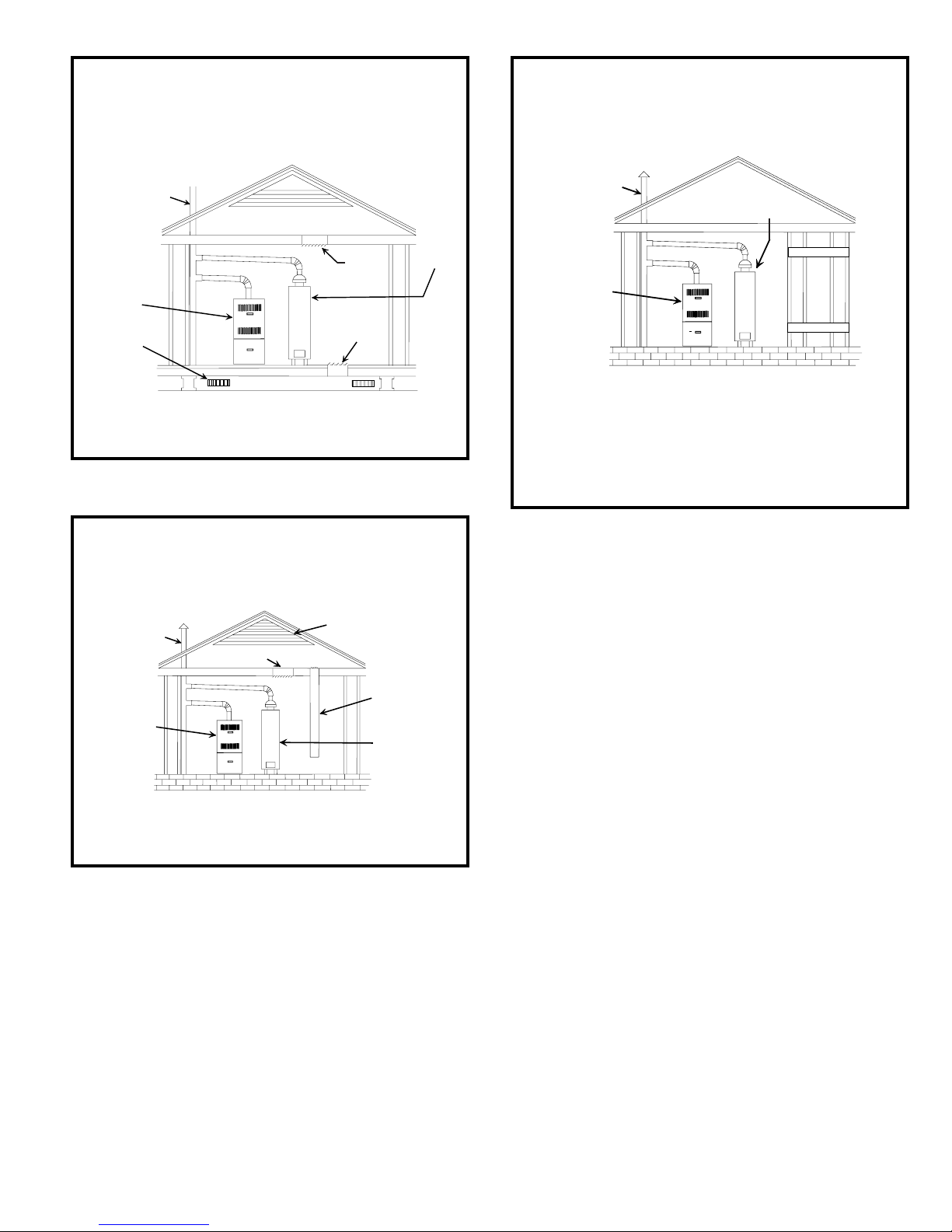
Equipment in Confined Space
All Air from Out side
(Inlet Air from Crawl Sp ace and
Outlet Air to V entilated Attic)
Equipment in Confined Space
All Air from Out side
(All Air Through Horizontal Ducts)
Chimney or
Gas Vent
Furnace
Ventilation
Louvers
(For unheated
crawl space)
Note: The inlet and outlet air opening shall each have a free area of
at least one square inch per 4000 BTU per hour of the total
input rating of all equipment in the enclosure.
Ventilation Louvers
(Each end of attic)
Outlet
Air
Inlet
Air
Water
Heater
Figure 4
Equipment in Confined Space
All Air from Out side
(All Air Through V entilated Attic)
Chimney or
Gas Vent
Outlet Air
Furnace
Ventilation Louvers
(Each end of attic)
Inlet Air
(Ends 12”
above bottom)
Water
Heater
Chimney or
Gas Vent
Water Heater
Outlet Air
Furnace
Inlet Air
Note: Each air duct opening shall have a free area of at least one
square inch per 2000 BTU per hour of the total input rating of
all equipment in the enclosure. If the equipment room is
located against an outside wall and the air openings communicate directly with the outdoors, each opening shall have a free
area of at least one square inch per 4000 BTU per hour of the
total input rating of all other equipment in the enclosure.
Figure 6
come from the outdoors by way of an attic, crawl
space, air duct, or direct opening.
2. If indoor combustion air is used, there must be no
exposure to the substances listed in item 5.
3. All provisions for indoor combustion air must meet the
requirements for combustion air indicated in the
National Fuel Gas Code, ANSI Z223.1/NFPA 54 (latest
edition), and/or any applicable local codes. In Canada,
see CSA B149.1, Natural Gas and Propane Installation Codes (latest edition).
Note: The inlet and outlet air opening shall each have a free area of
at least one square inch per 4000 BTU per hour of the total
input rating of all equipment in the enclosure.
Figure 5
Another option is to use horizontal combustion ducts (see
Figure 6). If horizontal combustion ducts are run, 1 square
inch per 2000 BTU/HR is required.
Contaminated Combustion Air
Excessive exposure to contaminated combustion air will
result in safety and performance related problems. The
recommended source of combustion air is outdoor air.
However, the use of indoor air in most applications is
acceptable if the following guidelines are followed:
1. If the furnace is installed in a confined space, it is
recommended that the necessary combustion air
# 45464K003 Page 5
4. The following types of installation may require outdoor air for combustion, due to chemical exposures:
• Commercial buildings
• Buildings with indoor pools
• Furnaces installed in laundry rooms
• Furnaces installed in hobby or craft rooms
• Furnaces installed near chemical storage areas
5. Exposure to the following substances in the combustion
air supply may also require outdoor air for combustion:
• Permanent wave solutions
• Chlorinated waxes and cleaners
• Chlorine-based swimming pool chemicals
• Water softening chemicals
• Deicing salts or chemicals
• Carbon tetrachloride
• Halogen-type refrigerants
• Cleaning solvents (such as perchloroethylene)
Page 6
• Printing inks, paint removers, varnishes, etc.
• Cements and glues
• Antistatic fabric softeners for clothes dryers
• Masonry acid washing materials
• Chlorinated laundry products
• Hydrochloric acid
Venting
This furnace has a fan-assisted combustion system
designed for vertical venting into a suitable chimney or
listed gas vent, and is classified as a Category I furnace
as shipped from the factory.
If this furnace is used to replace an existing furnace,
it is possible that the existing venting system is not
suitable for venting this furnace. Furthermore, the
existing venting system may have to be modified to
properly vent any other gas appliance, such as a water
heater, that remains connected to it. Carefully read the
Vertical Venting, Sidewall Venting, and Existing Vent
Systems sections that follow to determine proper venting
practices for the installation.
vent connector is permissible only in conditioned
space. Use Doublewall Type B vent pipe through
unconditioned space such as attics and crawl
spaces. The vent material used should be in accor-
dance with the National Fuel Gas Code, ANSI Z223.1/
NFPA 54 (latest edition) or the CSA B149.1, Natural
Gas and Propane Installation Codes and local codes.
Fan-assisted combustion system Category I furnaces
shall not be vented into single wall metal vents.
4. The vent connector must have an upward slope toward
the chimney on all horizontal runs of at least 1/4" per
foot of horizontal run and should be supported by a
sheet metal strap. The vent pipe connection must be
secured to the induced draft blower outlet. A single
screw is sufficient. On G1N80BR and CG80RB models,
a hole in the door hook will allow access to the blower
outlet without removing the door hook.
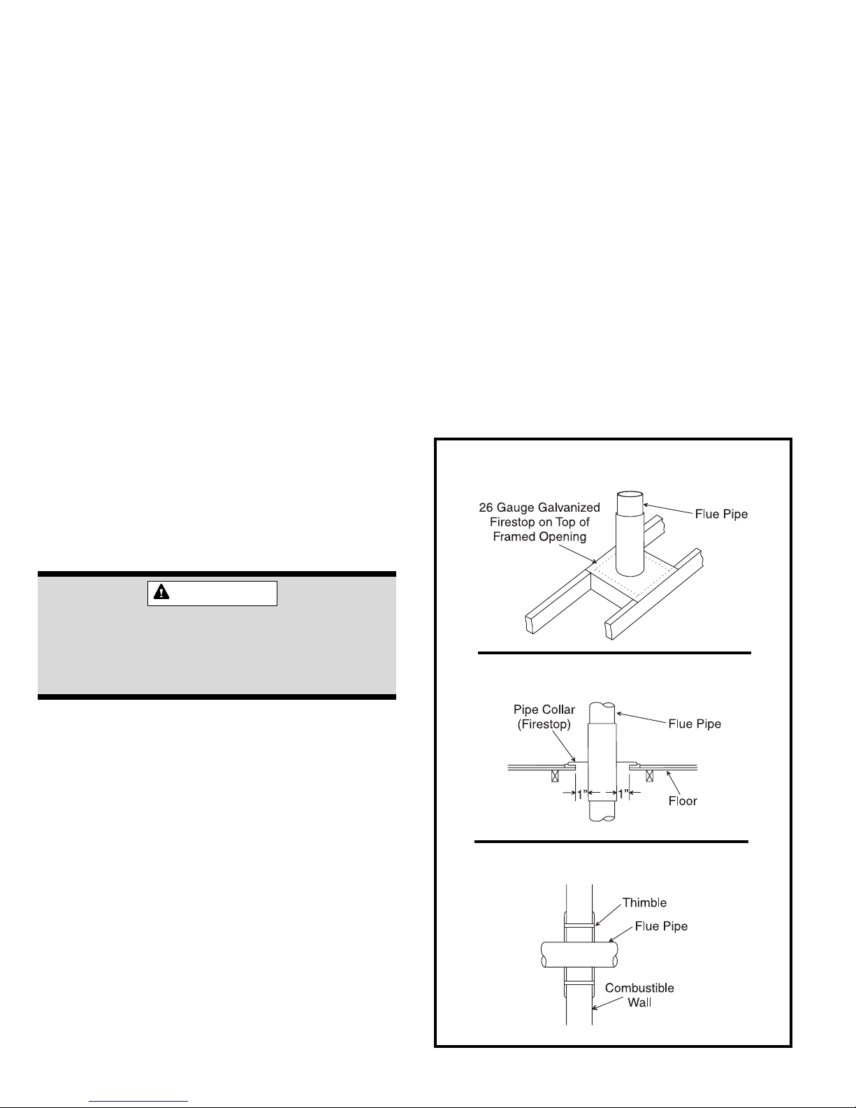
5. All vents passing through floors, ceilings, and walls
must be firestopped according to the requirements of
the National Fuel Gas Code (see Figure 7).
Installation shall be in accordance with Parts 7 and 11 of
the National Fuel Gas Code, ANSI Z223.1/NFPA 54 (latest
edition) and/or Section 7 and Appendix B of the CSA
B149.1, Natural Gas and Propane Installation Codes
(latest edition); local building codes; vent manufacturer
instructions; and these instructions.
IMPORT ANT
For 100K, 125K, and 150K BTUH input models,
the minimum vent connector diameter is 5". The
transition from 4" diameter flue outlet to 5"
diameter pipe must be made at the flue outlet.
Vertical Venting
Category I furnaces must be vented vertically or nearly
vertically. Common venting and multistory venting are
permitted when done in accordance with applicable codes,
such as local and national codes.
The venting system should be designed in accordance with
the “FAN” columns in the venting tables in the latest editions
of the National Fuel Gas Code, ANSI Z223.1/NFPA 54 or the
CSA B149.1, Natural Gas and Propane Installation Codes.
Vent Through Ceiling
Vent Through Floor
V ent Through W all
1. Consult local building codes for installation requirements.
2. The vent connector should be as short as possible with
the least number of elbows and angles to do the job.
3. It is recommended a minimum of 26 gauge galvanized
flue pipe be used. Use of single-wall vent pipe for the
Figure 7
# 45464K003Page 6
Page 7

6. The furnace shall be connected to a factory-built
chimney or vent complying with a recognized standard, or a masonry or concrete chimney lined with a
lining material acceptable to the authority with jurisdic-
tion. Venting into an unlined chimney or a single
wall metal vent is prohibited in all cases. A lined
chimney may be used if a draft hood equipped
appliance, such as a water heater, is connected to
the same flue (see Figures 8 and 9).
7. Extend the vent connector into the chimney so that it
is flush with the inside of the flue liner. Seal the joint
between the pipe and the liner.
8. Masonry chimneys serving fireplaces cannot be used
for venting purposes unless the fireplace opening is
permanently sealed.
9. A vent connector serving this appliance must not be
connected into any portion of mechanical draft systems operating under positive pressure.
10. The vent pipe must not be connected to a chimney
flue serving a solid fuel appliance.
11. A manual damper, barometric draft regulator, or flue
restrictor must not be installed between the furnace
and the chimney.
12. Where local experience indicates that condensate may
be a problem, the vent shall be constructed to prevent
condensation from entering the combustion blower.
Provision shall be made to drain off the condensate
(see Figures 8 and 9).
14. All vent pipe run through unconditioned areas or
outside shall be constructed of factory-built chimney
sections (see Figure 8).
15. Multistory venting is allowed as permitted by the
National Fuel Gas Code or local codes.
16. Install all vents in accordance with the vent
manufacturer’s instructions. For unlisted material,
install in accordance with the National Fuel Gas Code.
17. Vent terminals must be installed in accordance with
the vent terminals listing or in accordance with the
National Fuel Gas Code, ANSI Z223.1/NFPA 54 (latest
edition) or the CSA B149.1, Natural Gas and Propane
Installation Codes, and local codes.
Sidewall Venting
This furnace can be sidewall (horizontally) vented with a
listed sidewall venter, such as Field Controls Model SWG4HD with CK-43 Control Kit, or Tjernlund Model GPAK-JT.
Category I venting classification is maintained when vented
in this manner. The furnace, power venter, and control kit
(where applicable) must be installed in accordance with their
installation instructions and all applicable codes.
The following limitations also apply to the two previously
mentioned venters.
Vent pipe diameter: 4"
Minimum vent pipe length: 4'
Maximum vent pipe length: 25'*
Maximum number of 90° elbows: 4
13. All unused chimney openings should be closed.
Factory-Built Chimney V enting
Factory-Built
Chimney
Cleanout
* When fewer than four elbows are used, maximum vent
pipe length can be increased by 5' per unused elbow.
Masonry Chimney Venting
Liner
Masonry
Chimney
Cleanout
Figure 8
# 45464K003 Page 7
Figure 9
Page 8

For Canadian installations, only the Field Controls
venter and control kit mentioned above are authorized by CSA for use with this furnace.
See Figure 11 for information on where the sidewall vent
terminal can and cannot terminate.
Existing Venting Systems
When an existing Category I furnace is removed or replaced,
the original venting system may no longer be sized to
properly vent the attached appliances. An improperly sized
venting system can result in spillage of flue products into the
living space, the formation of condensate, leakage, etc. See
the WARNING box below for proper test procedure.
Circulating Air Supply
When the furnace is installed so that the supply ducts
carry air circulated by the furnace to areas outside the
space containing the furnace, the return air shall be
handled by a duct or ducts sealed to the furnace casing
and terminated outside the space containing the furnace.
A return air duct system is recommended. If the unit is
installed in a confined space or closet, a return connection
must be run, full size, to a location outside the closet. The
air duct in the closet must be tight to prevent any entrance
of air from the closet into the circulating air.
If there is no complete return air duct system, the return air
connection must be sealed to the furnace casing and run
full size to a location outside the utility room or space
housing the furnace to prevent a negative pressure on the
venting system.
CAUTION
When an air conditioning unit is used in
conjunction with the furnace, the evaporator
coil must be installed in the discharge (supply) air. Do not install an evaporator coil in the
return air; excessive condensation will occur
within the furnace.
WARNING
CARBON MONOXIDE POISONING HAZARD
Failure to follow the steps outlined below for each appliance connected to the venting system being placed into operation could result in carbon monoxide poisoning or death.
The following steps shall be followed for each appliance connected to the venting system being placed into operation,
while all other appliances connected to the common venting system are not in operation:
1. Seal any unused openings in the common venting system.
2. Visually inspect the venting system for proper size and horizontal pitch, as required in the National Fuel Gas Code,
ANSI Z223.1/NFPA 54 (latest edition) or the CSA B149.1 Natural Gas and Propane Installation Codes and these
instructions. Determine that there is no blockage or restriction, leakage, corrosion, or other deficiencies which could
cause an unsafe condition.
3. As far as practical, close all building doors and windows between the space in which the appliance(s) connected to the
venting system are located and other spaces in the building.
4. Close fireplace dampers.
5. Turn on clothes dryers and any appliance not connected to the venting system. Turn on any exhaust fans, such as range
hoods and bathroom exhausts, so they are operating at maximum speed. Do not operate a summer exhaust fan.
6. Follow the lighting instructions. Place the unit being inspected in operation. Adjust the thermostat so appliance is
operating continuously.
7. Test for spillage from draft hood equipped appliances at the draft hood relief opening after 5 minutes of main burner
operation. Use the flame of a match or candle.
8. If improper venting is observed during any of the above tests, the venting system must be corrected in accordance with
the National Fuel Gas Code, ANSI Z223.1/NFPA 54 (latest edition) and/or the CSA B149.1 Natural Gas and Propane
Installation Codes.
9. After it has been determined that each appliance remaining connected to the venting system properly vents when tested
as outlined above, return doors, windows, exhaust fans, fireplace dampers, and any other gas-fired burning appliance to
their previous conditions of use.
# 45464K003Page 8
Page 9

Sidewall V ent Terminal Clearances
V
Vent Terminal
Air Supply Inlet
X
Area Where Terminal
Is Not Permitted
1
snoitallatsnInaidanaC
A
ynoclabro,kced,hcrop,adnarev,edargevobaecnaraelC )mc03(sehcni21)mc03(sehcni21
2
snoitallatsnISU
<secnailpparof)mc51(sehcni6
03(sehcni21,)Wk3(hutB000,01
B
denepoebyamtahtroodrowodniwotecnaraelC
3(hutB000,01>secnailpparof)mc
,)Wk03(hutB000,001<dna,)Wk
>secnailpparof)mc19(sehcni63
gninepo
foedisotrowoleb)m2.1(teef4
evoba)m003(toof1;gninepo
)Wk03(hutB000,001
C
wodniwdesolcyltnenamrepotecnaraelC **
ehtevobadetacoltiffosdetalitnevotecnaraelclacitreV
D
ehtmorf)mc16(teef2foecnatsidlatnozirohanihtiwlanimret
**
lanimretehtfoenilretnec
E
evnuotecnaraelC **
F
G
H
I
tiffosdetalitn
renrocedistuootecnaraelC **
renrocedisniotecnaraelC **
ylbmessarotaluger/retem
evobadednetxeenilretnecfoedishcaeotecnaraelC
51thgiehanihtiw)mc19(teef3
ehtevoba)m5.4(teef
*
ylbmessarotaluger/retem
teltuotnevrotalugerecivresotecnaraelC )mc19(teef3*
<secnailpparof)mc51(sehcni6
J
ecnailpparehtoynaottelnirianoitsubmoc
ehtrognidliubottelniylppusrialacinahcemnonotecnaraelC
3(hutB000,01>secnailpparof)mc
,)Wk03(hutB000,001<dna,)Wk
>secnailpparof)mc19(sehcni63
gninepo
03(sehcni21,)Wk3(hutB000,01
foedisotrowoleb)m2.1(teef4
evoba)m003(toof1;gninepo
)Wk03(hutB000,001
K
L
ytreporpcilbupno
M
1
In accordance with the current CSA B149.1, Natural Gas and
Propane Installation Code
2
In accordance with the current ANSI Z2223.1/NFPA 54, National
Fuel Gas Code
†
A vent shall not terminate directly above a sidewalk or paved
driveway that is located between two single family dwellings and
serves both dwellings.
# 45464K003 Page 9
telniylppusrialacinahcemaotecnaraelC )m38.1(teef6
detacolyawevirddevaproklawedisdevapevobaecnaraelC
ynoclabro,kced,hcrop,adnarevrednuecnaraelC )mc03(sehcni21*
‡
Permitted only if veranda, porch, deck, or balcony is fully open on a
†
)m31.2(teef7)m31.2(teef7
‡
01nihtiwfievoba)mc19(teef3
yllatnoziroh)m3(teef
minimum of two sides beneath the floor.
* For clearances not specified in ANSI Z2223.1/NFPA 54 or CSA
B149.1, the following statement shall be included:
“Clearance in accordance with local installation codes and the
requirements of the gas supplier and the manufacturer’s installation
instructions.”
Figure 10
Page 10

When installing a CAM coil in a horizontal position with a
horizontal gas furnace, always keep the open end of the
A-coil facing the supply air outlet of the furnace (blow into
the open end of the A-coil). The A-coil should point away
from the supply air outlet of the furnace (see Figure 11).
Correct Positioning of CAM Coil in the
Horizontal Position with a Gas Furnace
Correct
Return
Supply
Incorrect
Return
Supply
WARNING
When side return is desired on a furnace with
an open bottom, the bottom must be sealed
with a piece of sheet metal large enough to
cover the entire opening. Failure to connect a
return air duct to the bottom, or to enclose
the bottom when side return is desired, may
result in combustion products being drawn
into the circulating air stream which could
result in asphyxiation.
Horizontal Installations
G1N80BR, G1N80BT, CG80RB, and CG80TB series
furnaces can be horizontally installed for airflow right to left
or left to right. These furnaces are to be installed so that
the burner and blower access panels are in a vertical
plane; they are NOT to be installed such that these panels
are in a horizontal plane (see Figure 1 on page 2). Never
install any furnace on its back.
Figure 11
If a cooling coil is not installed with the furnace, then a
removable access panel should be provided in the supply
plenum for purposes of inspecting the heat exchanger.
This opening shall be accessible when the furnace is
installed, and shall be of such size that the heat exchanger
can be viewed for possible openings using light assistance
or a probe can be inserted for sampling the air stream. The
cover for the opening shall be leaktight.
Upflow Installations
G1N80BU, G1N80BT, CG80UB, and CG80TB series
furnaces can be installed as upflow units with either a side
or bottom air return. For units that do not include a side
return filter rack, kit AFILT524 can be used. Bottom filter
kit AFILT529 can be used with all G1N80BU, G1N80BT,
CG80UB, and CG80TB series furnaces.
For side return installation, a full-size return air opening
must be cut in the side panel. A starter hole and corner
embossments are provided in each side (see Figure 13 in
the Filters section).
Counterflow (Downflow) Installations
G1N80BR and CG80RB furnaces may be installed directly
on the supply plenum or coil cabinet if the furnace is
installed on a non-combustible floor.
For installations on combustible flooring, a special base
must be ordered and used. (See the Accessories section on
page 18 for more information.) To install the special base:
1. Cut a hole in the floor, sized to provide 1" clearance
between all four sides of the duct and the edge of the
flooring (see Figure 12). The four angles on the base
assembly should recess into the floor joists and the
base should rest on all four outside flanges.
2. Construct duct connections with 1" to 1-3/4" right
angle flanges, and long enough to extend below the
floor joists.
3. Drop the duct connections through the top of the base
assembly with the right angle flanges in good contact
with the glass tape on top of the base assembly.
4. Carefully position furnace over right angle duct flanges.
Filters
To provide sufficient filter area for installations requiring
more than 1600 CFM nominal air delivery, return air will
have to be brought through both sides of the furnace,
through one side and the bottom, or optional filter rack
AFILTHA7 may be used.
Filters are not supplied with CG80UB, CG80TB, or
CG80RB series furnaces.
G1N80BU Models
A filter rack and washable 16" x 25" x 1/2" filter are
supplied with each G1N80BU furnace. (Models designed
# 45464K003Page 10
Page 11

Combustible Floor Installation
(Counterflow Models Only)
Filter Rack Installation
Filter Rack Mounting Hole
Screw
Woven
Glass Tape
Combustible
Figure 12
Base
Assembly
Flooring
Furnace
1"
Duct
Front of Cabinet
Corner Embossments
Filter Rack
Figure 13
installer’s responsibility to install properly sized filters in
accordance with Table 1 on page 12.
If filters are needed at the furnace only, use the following kits:
• AFILT524 for side return on upflow installations.
• AFILT529 for bottom return on upflow installations or
horizontal installations of G1N80BT or CG80TB furnaces.
• AFILT525 for counterflow installations of G1N80BR or
CG80RB furnaces.
Other filter accessories are also available from the manufacturer including a full line of indoor air quality products. For
information on these products, contact the local distributor.
for more than 1600 CFM nominal air delivery include two of
each.) The filter rack is to be installed between the return
air duct and the side of furnace. Refer to Figure 13 and the
following instructions to install the filter rack:
1. Using the corner embossments as a guide, mark and
cut a full-size opening in the side panel(s).
2. Using the filter rack as a template, mark and drill four
7/64" diameter screw holes in the side panel(s).
3. With the filter access opening toward the front of the
furnace, use sheet metal screws to fasten the rack(s)
to the side panel(s).
4. Install the filter(s) in the rack(s), mesh side of filter
towards furnace.
Model AFIL THA7 external filter frame accessory is available for single side return air connection in installations
requiring more than 1600 CFM nominal air delivery .
G1N80BT , CG80TB, G1N80BR, and CG80RB Models
Filters are not supplied with G1N80BT, CG80TB, G1N80BR,
or CG80RB series furnaces since filters are commonly
located behind a return grille for ease of servicing. It is the
Upflow Model Filter Location
Side
Base
Filter
BOTTOM RETURN
R/A Duct
Filter Rack
Filter - Slides in from Front of Unit
SIDE RETURN
Figure 14
# 45464K003 Page 11
Page 12

Minimum Filter Requirements
(see Figure 15). The screws must be re-installed in the
vest panel after the insert s are removed.
wolfriA
rotpircseD
90084
01 084
21675
41 276
61867
22,02 069
1. The Airflow Descriptor is the two digits following the “D” in
the model number.
2. Areas and dimensions shown for permanent filters are
based on filters rated at 600 feet per minute face velocity.
3. Typical filter sizes are shown; however, any combination
of filters whose area equals or exceeds the minimum
area shown is satisfactory.
aerA.niM
).ni.qs(
eziS
).ni(
52x02
52x02
02x61
02x02
02x02
52x02
sretliFelbasopsiD sretliFtnenamreP
.ytQ
1042
1 042
2882
2 633
2483
2 084
eziS
aerA.niM
).ni.qs(
).ni(
02x61
1
02x61
1
02x61
1
02x02
1
02x02
1
52x02
1
Table 1
Gas Supply and Piping
Refer to the furnace rating plate to make sure the furnace
is equipped to burn the gas supplied (natural or propane).
.ytQ
NOx Insert
Location
Figure 15
WARNING
FIRE OR EXPLOSION HAZARD
Failure to follow the safety warnings exactly
could result in serious injury, death, or property damage.
WARNING
Any conversion of a natural gas unit to propane gas must be done by qualified personnel using a conversion kit available from the
manufacturer, following the instructions in the
conversion kit. If done improperly, overfiring of
the burners and improper burner operation
can result. This can create carbon monoxide
which could cause asphyxiation.
WARNING
When converting a low NOx furnace (desig-
nated by an “L” in the model number, such as
G1N80BU100D20CL-1A) to propane, the
NOx inserts must be removed. Failure to
remove the inserts can create a situation
where carbon monoxide is produced which
may lead to asphyxiation.
Never test for gas leaks with an open flame.
Use a commercially available soap solution
made specifically for the detection of leaks to
check all connections. A fire or explosion may
result causing property damage, personal
injury, or loss of life.
Gas supply piping should be installed in accordance with
local codes and the regulations of the utility. Piping must be
of adequate size to prevent undue pressure drop. Consult
the local utility or gas supplier for complete details on special
requirements for sizing gas piping.
If local codes allow the use of a flexible gas appliance
connector, always use a new listed connector. Do not use
a connector which has previously serviced another gas
appliance.
Pipe connections must be tight, and a non-hardening pipe
compound resistant to liquefied petroleum gases should
be used.
To remove the NOx inserts, first take out the burners. After
removing the burners, remove the screw holding each
insert and pull the insert from the combustion chamber
Connect gas pipe to furnace controls providing a ground joint
union as close to the controls as is possible to facilitate
removal of controls and manifold. Provide a drip leg on the
outside of furnace. A manual shutoff valve shall be installed
# 45464K003Page 12
Page 13

in the gas line, outside the unit, 5' above the floor, or in
accordance with any local codes. A test gauge connection
must be installed with a 1/8" NPT plugged tapping immediately upstream of the shutoff valve (see Figure 16).
Gas Connection
Manual
Gas Valve
Union
1/8" NPT
Plugged
Tapping
After gas piping is complete, carefully check all piping
connections (factory and field) for gas leaks. Use a leak
detecting solution or other preferred means. Some soaps
used for leak detection are corrosive to certain
metals. Carefully rinse piping thoroughly after leak
detection has been completed.
Electrical Wiring
WARNING
Te e
Drip Leg
Cap
Upflow/
Counterflow
Installation
Manual
Gas Valve
Union
Te e
Drip Leg
Cap
1/8" NPT
Plugged
Tapping
Horizontal
Installation
Figure 16
The furnace must be isolated from the gas supply piping
system by closing the individual manual shutoff valve
during any pressure testing of the gas supply piping
system at test pressure equal to or less than 1/2 psig
(3.5 kPa) or 14" W.C. If the piping system is to be tested at
pressures in excess of 1/2 psig (3.5 kPa), the furnace and
its appliance main gas valve must be disconnected from
the gas supply piping system.
Risk of electrical shock. Disconnect electrical
power at the circuit breaker or service panel
before making electrical connections. Failure
to disconnect power supplies can result in
property damage, personal injury, or death.
The furnace must be grounded and wired in accordance
with local codes or, in the absence of local codes, with the
National Electrical Code ANSI/NFPA No. 70 (latest edition)
and/or CSA C22.1 Electrical Code (latest edition) if an
external electrical source is utilized.
In all instances, other than wiring for the thermostat, the
wiring to be done and any replacement of wire shall
conform with the temperature limitation for Type T wire –
63°F (35°C) rise.
Connect a sufficiently sized wire with ground to the furnace’s
line voltage connections and ground lug. Refer to the
furnace rating plate for electrical characteristics to be used
in sizing field supply wiring and over-current protection.
The line voltage supply should be routed through a
readily accessible disconnect located within sight of the
furnace. A junction box on the furnace side panel is
provided for line voltage connections. Refer to the furnace
wiring diagram for specific connection information.
Proper polarity of the supply connections (“HOT”
and “NEUTRAL”) must be observed to ensure that
safety controls provide the protection intended.
A connection to the ground lug and actual earth ground
(typically a ground stake or buried steel pipe) must be
maintained for proper operation.
WARNING
The gas valve supplied with this furnace is
rated at 1/2 psig maximum. Any higher pressure may rupture the pressure regulator diaphragm and may cause overfiring of the burners
and improper burner operation. The overfiring
may result in the creation of carbon monoxide
which could cause asphyxiation.
# 45464K003 Page 13
Thermostat
Install a room thermostat according to the instructions
furnished with it. Select a location on an inside wall that is
not subject to drafts, direct sunshine, or other heat
sources. The initial heat anticipator setting should be equal
to the total current draw of the control circuit.
Low voltage thermostat connections are to be made to the
blower control board as indicated on the wiring diagram.
Page 14

Continuous Blower Operation
What to do if you smell gas:
If continuous blower operation on low speed is desired,
connect the lowest speed motor tap to the “CONT” terminal
on the blower control board (refer to the furnace wiring
diagram.) The blower will operate on low speed whenever
main power is connected to the furnace, except when it
operates on heating or cooling speed during thermostat
call for heat or cooling. This constant air terminal is
intended for low speed only . If a motor is wired for a
higher speed, the increased amp draw could cause the
board control to fail and void the warranty.
Humidifier
Terminals are provided on the blower control board for
connection to a 120-volt humidifier. The “HUM” terminal is
energized whenever the thermostat calls for heat. Refer to
furnace wiring diagram for specific connection information.
Electronic Air Cleaner
Terminals are provided on the blower control board for
connection of a 120-volt electronic air cleaner. The “EAC”
terminal is energized whenever the thermostat calls for
heat, cooling, or continuous blower. Refer to the furnace
wiring diagram for specific connection information.
Twinning
• Do not try to light any appliances.
• Extinguish any open flame.
• Do not touch any electric switch; do not use any phone
in your building.
• Immediately call your gas supplier from a neighbor’s
phone. Follow the gas supplier’s instructions.
• If you cannot reach your gas supplier, call the fire
department.
Do not use this furnace if any part has been under water.
Immediately call a qualified service technician to inspect
the furnace and to replace any part of the control system
and gas control which has been under water.
IMPORTANT: Refer to the Lighting Instruction label on
the furnace for instructions on operating the specific
controls used on your unit.
To Start Furnace:
CAUTION
Be sure the manual gas control has been in
the “OFF” position for at least 5 minutes
before starting the unit. Do not attempt to
manually light the burners.
The blower control board is designed to permit “twinning” of
furnaces (two furnaces connected to a common supply
and return air system, and controlled by one thermostat).
An accessory kit must be ordered from the manufacturer.
Specific wiring and operating instructions are included
with the kit.
Each furnace must have its own dedicated vent system.
START -UP
Lighting Instructions
For Your Safety, Read Before Operating
WARNING
If you do not follow these instructions exactly,
a fire or explosion may result causing property damage, personal injury, or loss of life.
These furnaces are equipped with an ignition device which
automatically lights the burner. Do not try to light the
burner by hand.
1. Set the room thermostat to lowest setting.
2. Remove burner access door.
3. Move the gas control knob to the “ON” position. Use
only your hand to turn the gas control knob; never use
tools. If the knob will not turn by hand, don’t try
to repair it; call a qualified service technician. Force or
attempted repair may result in a fire or explosion.
4. Replace the burner access door.
5. Turn on the electrical power to the furnace.
6. Set the room thermostat to a point above room temperature to light the main burners. After the burners have
ignited, set the room thermostat to desired temperature.
To Shut Down Furnace:
1. Set the room thermostat to the lowest setting.
2. Turn off all electric power to the furnace.
3. Remove burner access door.
Before operating, smell all around the appliance area for
gas. Be sure to smell next to the floor because some gas
is heavier than air and will settle on the floor.
4. Shut off the gas by moving the gas control knob to the
“OFF” position.
5. Replace the burner access door.
# 45464K003Page 14
Page 15

WARNING
Should overheating occur or the gas supply
fail to shut off, shut off the manual gas valve
to the appliance before shutting off the electrical supply.
OPERATION
The call for cooling has priority over continuous fan
operation while a call for heating has priority over both a
call for cooling or continuous fan. Ignition lockouts for any
reason do not affect cooling operation.
As cooling demand is met, the thermostat de-energizes
the R-Y circuit of the control board. After a 60-second
cooling “off” delay, the control de-energizes the cooling
speed fan. At the end of the cooling “off” delay period, the
control returns to the standby mode.
Sequence of Operation
Heating
During a call for heat the thermostat closes the R-W circuit
of the control board. The control board verifies limit
switches are closed and pressure switch is open. The
induced draft blower relay closes causing the blower to
run. As vent pressure is developed by the induced draft
blower, the pressure switch closes. After a 15-second prepurge, the control energizes the hot surface ignitor. After
the 7-second warmup time, the control energizes the main
gas valve causing the main burners to ignite. The hot
surface ignitor is de-energized 3 seconds after the main
valve opens. If flame is sensed during this time the main
valve remains energized and the control starts the
30-second heat blower “on” delay.
As heating demand is met, the thermostat de-energizes the
R-W circuit. The control de-energizes the main valve causing
the burners to shut off. The induced draft blower shuts off
after a 15-second post-purge delay. The circulating air blower
will continue to operate until the user-selectable heat blower
“off” delay expires. The control return to standby mode once
the heat blower “off” delay expires.
Controls
Following is a description of the operation of some of the
controls used in this furnace. All models use one of each
control, except as noted.
Pressure Switch
The pressure switch is a normally open switch that
monitors combustion air flow. Inadequate air flow resulting
from excessive venting system restriction or a failed
combustion blower will cause the switch to remain open.
Rollout Switch
The rollout switch is a normally closed switch that opens
when abnormal temperatures exist in the burner area. This
can be caused by a restricted heat exchanger causing
main burner flame to “roll out” into the vestibule area or
burner box.
This switch must be manually reset by pushing the button
on top to restore furnace operation. G1N80BR, G1N80BT,
CG80RB, and CG80TB series units incorporate two rollout
switches.
Fan “On”
During a fan “on” call, the thermostat energizes the R-G
circuit of the control board, immediately causing the fan to
energize the COOL speed. The fan remains energized as
long as the thermostat calls for fan “on” operation.
If a call for cooling is energized during a fan “on” call, the fan
continues to operate at the COOL speed. If a call for heat is
energized during a fan “on” call, the control de-energizes the
fan immediately and begins the heat call/ignition sequence.
At the end of the fan “on” call the thermostat de-energizes
the R-G circuit of the control, causing the fan to be deenergized immediately.
Cooling
During a call for cooling, the thermostat energizes the R-Y
circuit of the control board. After a 1-second cooling “on”
delay, the control energizes the cooling fan speed. If the fan
is already energized, it remains running and does not de-
energize for the 1-second cooling fan “on” delay.
# 45464K003 Page 15
Primary Limit Control
This is a normally closed control that opens if abnormally
high circulating air temperatures occur. It is an automatic
reset control.
Auxiliary Limit Control
This is a normally closed control, located on the circulating
air blower housing, that opens under abnormal
“reverse air flow” conditions that could occur in a
counterflow or horizontal installation if the circulating air
blower fails. It is an automatic reset control.
G1N80BU and CG80UB models do not include an auxiliary
limit control.
Interlock (Blower Door) Switch
When the blower door is removed, the interlock switch
breaks the power supply to the burner controls and blower
motor. The switch operation must be checked to confirm it
is operating correctly.
Page 16

Blower Control Board
The blower control board operates the circulating air
blower, the combustion blower, and any accessories
connected to it. These models feature user-selectable
blower “off” delay times (60, 90, 120, and 180 seconds)
that are factory set to provide a 120-second blower “off”
delay on heating (see wiring diagram on page 19).
For Natural Gas: Check the furnace rate by observing the
gas meter, when available, making sure all other gas
appliances are turned off. The test hand on the meter
should be timed for at least one revolution. Note the
number of seconds for one revolution.
Cubic Feet Per RevolutionBTU/HR
INPUT # Seconds Per Revolution
=
x 3600 x
Heating
Value
Refer to the furnace wiring diagram while using the
following procedure to change motor speed:
1. Turn off electrical power to the unit.
2. Connect the desired speed tap for cooling on the
blower control board.
3. For heating speed, check the temperature rise and, if
necessary, adjust blower speed tap to maintain temperature rise within the range shown on furnace rating plate.
To use the same speed tap for both heating and
cooling, install a piggyback terminal on the speed tap
using a short jumper. Wire 1/4" quick connect termi-
nals on both ends to jumper the “HEAT” and “COOL”
speed on the blower control board.
4. The remaining speed taps must be connected to dummy
terminals marked “PARK” on the blower control board.
Checking and Adjusting Gas Input
The minimum permissible gas supply pressure for the
purpose of input adjustment is 5" W.C. for natural gas and
11" W.C. for propane gas. This furnace requires conversion
for use with propane (see Accessories section on page 18
for correct kit). The maximum inlet gas supply pressure is
10.5" W.C. for natural gas and 13" W.C. for propane.
The heating value of the gas can be obtained from the
local utility company.
For Propane Gas: The only check for the furnace rate is to
properly adjust the manifold pressure using a manometer
and the information provided in Tables 2 and 3. Typical
manifold set point for installations at altitudes from 0 to
4500 feet above sea level is 10.0" W.C.
Temperature Rise
Check the temperature rise and, if necessary, adjust
blower speed to maintain temperature rise within the
range shown on the unit rating plate.
High Altitude
In both the United States and Canada, this furnace is
approved for operation at altitudes from 0 to 4500 feet
above sea level without any required modifications. From
4500 to 7500 feet, the gas manifold pressure needs to be
adjusted according to the information shown in Tables 2
and 3. To adjust the manifold pressure, refer to previous
section Checking and Adjusting Gas Input. For installations above 7500 feet, call Technical Service at 1-800-4485872 ext. 2610 for assistance.
MAINTENANCE
Gas input must never exceed the value shown on the
furnace rating plate. This furnace is equipped for rated
input at manifold pressures of 3.5" W.C. for natural gas and
10.0" W.C. for propane gas.
The manifold pressure can be measured by removing the
pipe plug in the downstream side of the gas valve and
connecting a water manometer or gauge.
To adjust the regulator, turn the adjusting screw on the
regulator clockwise to increase pressure and input; counterclockwise to decrease pressure and input.
CAUTION
The furnace rate must be within +/– 2% of the
appliance rating input.
WARNING
ELECTRICAL SHOCK, FIRE,
OR EXPLOSION HAZARD
Failure to follow the safety warnings exactly
could result in dangerous operation, serious
injury, death, or property damage.
Improper servicing could result in dangerous
operation, serious injury, death, or property
damage.
• Before servicing, disconnect all electrical
power to furnace.
• When servicing controls, label all wires prior
to disconnecting. Reconnect wires correctly.
• Verify proper operation after servicing.
# 45464K003Page 16
Page 17

Manifold Pressure vs. Altitude
saGlarutaN )PL(enaporP
edutitlA
).tf(
000284905.3872200.016669.0
0003 419 05.3 6912 00.01 9949.0
000418805.3611200.012339.0
0054 568 05.3 7702 00.01 9429.0
000594892.3930214.90098.0
0055 338 72.3 0002 53.9 0978.0
000681852.3469192.90868.0
0056 208 32.3 7291 42.9 0758.0
000778712.3198181.90648.0
0057 177 91.3 3581 21.9 0538.0
* Consult local utility for actual heating value.
Furnace Input = Input Factor x Nameplate Input
Above 7500 feet, call Technical Services at 1-800-4485872 ext. 2610.
gnitaeH
*eulaV
3
)
tf/UTB(
dlofinaM
erusserP
).C.W.ni(
gnitaeH
*eulaV
3
)
tf/UTB(
dlofinaM
erusserP
).C.W.ni(
Manifold Pressure vs. Altitude
(G1N80BU150 and CG80UB150 only)
)
saGlarutaN )PL(enaporP
dlofinaM
erusserP
).C.W.ni(
gnitaeH
*eulaV
3
tf/UTB(
)
dlofinaM
erusserP
tupnI
rotcaF
).C.W.ni(
tupnI
rotcaF
* Consult local utility for actual heating value.
Furnace Input = Input Factor x 148,000
Above 7500 feet, call Technical Services at 1-800-4485872 ext. 2610.
edutitlA
).tf(
000284914.3872200.016669.0
0003 419 14.3 6912 00.01 9949.0
000418814.3611200.012339.0
0054 568 14.3 7702 00.01 9429.0
000594802.3930214.90098.0
0055 338 81.3 0002 53.9 0978.0
000681861.3469192.90868.0
0056 208 41.3 7291 42.9 0758.0
000778721.3198181.90648.0
0057 177 11.3 3581 21.9 0538.0
gnitaeH
*eulaV
3
tf/UTB(
Table 2
It is recommended that this furnace be inspected by a
qualified service technician at the beginning of each heating
season.
Filters
Filters should be checked at least every 6 weeks. Disposable filters should be replaced when dirty, and permanent
filters should be cleaned regularly. It is important to keep the
air filters clean, as dirty filters can restrict airflow and the
blower and induced draft motors depend upon sufficient air
flowing across and through them to keep from overheating.
Main Burners
Light the burners and allow to operate for a few minutes to
establish normal burning conditions. Observe the main
burner flames. Compare this observation to Figure 17 to
determine if proper flame adjustment is present. Flame
should be predominantly blue in color and strong in appearance. Check that all burners are lit, and that the flame does
not impinge on the sides of the heat exchanger.
Distorted flame or yellow tipping of the natural gas main
burner flame, or long yellow tips on propane, may be
caused by lint accumulation or dirt inside the burner or
burner ports, at the air inlet between the burner and
manifold pipe, or obstructions over the main burner orifice.
Use a soft brush or vacuum to clean the affected areas.
# 45464K003 Page 17
Table 3
T ypical Flame Appearance
(Main Burners)
Heat
Exchanger
Burner
Gas
Manifold
Burner
Flame
(Blue Only)
Figure 17
Lubrication
The blower motor and induced draft motor are pre-lubricated by the manufacturer and do not require further
lubricating attention. However, the motors should be
cleaned periodically to prevent the possibility of overheating due to an accumulation of dust and dirt on the windings
or on the motor exterior.
Page 18

CONTROL SYSTEM DIAGNOSTICS
Fault Code History Button
Troubleshooting
The following visual checks should be made before
troubleshooting:
1. Check to see that the power to the furnace and the
blower control board is on.
2. The manual shutoff valves in the gas line to the
furnace must be open.
3. Make sure all wiring connections are secure.
4. Review the Sequence of Operation (see page 15).
Start the system by setting the thermostat above the room
temperature. Observe the system’s response. Then use the
information provided in this section to check the system’s
operation.
The furnace has a built-in, self-diagnostic capability. If a
system problem occurs, a fault code is shown by an LED
on the control board. The control continuously monitors its
own operation and the operation of the system. If a failure
occurs, the LED will indicate the failure code. The flash
codes are presented in Table 4.
Failure Codes
The control stores the last five fault codes in memory. A
pushbutton switch is located on the control (see Figure 18).
When the pushbutton switch is pressed and released, the
control flashes the stored fault codes. The most recent fault
code is flashed first; the oldest fault code is flashed last.
To clear the fault code history, press and hold the pushbutton
switch in for more than 5 seconds before releasing.
REPAIR PARTS
The following repair parts are available from the local
distributor. When ordering parts, include the complete
furnace model number and serial number which are
printed on the rating plate located on the furnace.
Control Group
Transformer
High limit control
Auxiliary limit (if used)
Gas valve
Ignition/blower control board
Flame sensor
Heat Exchanger Group
Heat exchanger
Flue box cover
Blower Group
Pressure switch
Blower door interlock switch
Combustion blower assembly
Flame rollout protector switch
Hot surface igniter
Combustion blower transition
DEL
sutatS
nODEL noitarepolamroN
hsalF1ffoevlavsaghtiwtneserpemalF
ffODEL
sehsalF2 fforecudnihtiwdesolchctiwserusserP
sehsalF3norecudnihtiwnepohctiwserusserP
sehsalF4 nepohctiwstimilhgiH
sehsalF5nepohctiwstuolloR
sehsalF6 tuokcolelcychctiwserusserP
sehsalF7noitingionoteudtuokcoL
sehsalF8 stuopordemalfynamoototeudtuokcoL
sehsalF9gnisahpegatloveniltcerrocnI
Table 4
noitpircseDtluaF
Blower housing assembly
Blower wheel
lortnocrolortnocotrewopoN
detcetedtluaferawdrah
Blower mount
Burner Group
Gas manifold
Blower motor mount
Blower motor capacitor
Main burners
Main burner orifices
Accessories
ALPKT572 Natural Gas to Propane Conversion Kit
ANGKT557 Propane to Natural Gas Conversion Kit
AFILTHA7 Single Side Filter Frame Kit
AFILT524 Side Return Filter Kit (Upflow Models)
AFILT525 Return Filter Kit (Counterflow Models)
AFILT529 Bottom Return Filter Kit
ATWIN579 Twinning Kit
ABASE511 Combustible Floor Base (14.5" cabinets)
ABASE512 Combustible Floor Base (17.5" cabinets)
ABASE568 Combustible Floor Base (21.0" cabinets)
ABASE569 Combustible Floor Base (24.5" cabinets)
# 45464K003Page 18
Page 19

# 45464K003 Page 19
Connection Diagram
P/N 45198-005
Figure 18
Page 20

Schematic Diagram
P/N 45198-005
Figure 19
# 45464K003Page 20
 Loading...