

Page 1
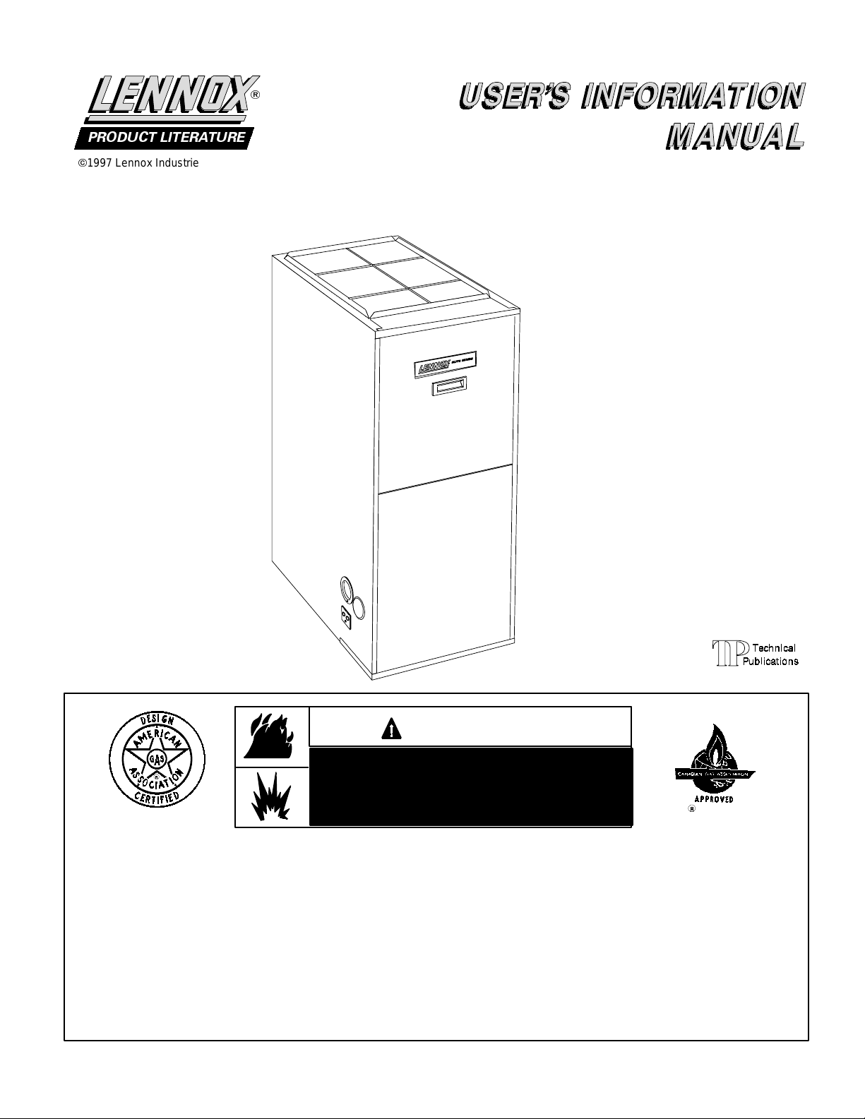
PRODUCT LITERATURE
¤
1997 Lennox Industries Inc.
Dallas, Texas,USA
503,738M
9/98
Supersedes 10/97
£
GHR26
SERIES
GAS FURNACE
If the information in this manual is not
followed exactly, a fire or explosion
may result causing property damage,
personal injury or loss of life.
Do not store or use gasoline or other
flammable vapor s and liquids in the
vic inity of this or any other app lianc e .
Installa tion a nd service must be perfor medbyaqualifiedinstaller,s er vice
agency or the gas s upplier.
LithoU.S.A.
WARNING
WHAT TO DOIF YOU SMELL GAS:
- Do not try to light any appliance.
- Extinguish any open flames.
- Do not touch any electrical switch; do not
use any phone in your building.
- Immediately call your gas s upplier from a
neighbor’s phone. Followthegas supplier’s
instr uctions.
- If you cannot reach your gas supplier, call
thefir e depar tment.
Page 1
Page 2

GHR26 Parts Identification (Downflow Application Shown)
CABINET
BLOWER MOTOR
COMBUSTION AIR PROVING
(PRESSURE) SWITCH
DuralokPlus
HEAT EXCHANGER
ASSEMBLY
EXHAUST PIPE
CONNECTION
CONDENSATE TRAP
TM
CONNECTION
BURNER
BOX
BURNERS
FIGURE 1
WARNING
Product contains fiberglass wool.
Disturbing the insulation in this product during
installation, maintenance, or repair will expose you
to fiberglass wool dust. Breathing this may cause
lung cancer. (Fiberglass wool is known to the State
of California to cause cancer.)
Fiberglass wool may also cause respiratory, skin,
and eye irritation.
To reduce exposure to this substance or for further
information, consult material safety data sheets
availablef rom addressshownbelow,orcontactyour
supervisor.
Lennox Industries Inc.
P.O. Box 799900
Dallas, TX 75379-9900
Important Directions
1- Keep the furnace area clear and free of combustible
material, gasoline, and other flammable vapors and
liquids. If installed in an insulated area, furnace must
be kept free of insulating material. Insulating material
may be combustible.
2- DO NOT obstruct air flow to unit. Unit must receive an
unobstructed flow of combustion and ventilating air.
FILTER
TOP CAP
BLOWER ACCESS
DOOR
CONTROL BOX
INTEGRATED
IGNITION/BLOWER
CONTROL
DOOR INTERLOCK
SWITCH
COMBUSTION AIR
BLOWER
GAS
VALVE
FRESH AIR INTAKE
CONNECTION
HEATING ACCESS
PANEL
FLAME SIGHT
GLASS
3- DO NOT store chlorine or fluorine products near unit
or introduce these products into the combustion air.
These products can cause furnace corrosion.
DO NOT draw the return air from a room where
4-
another gas appliance (ie., a water heater) is
installed.
Eventhoughthis furnacedraws itscombustion air from outside of the structure, other gas appliancesthatshareautility roommay not.Whenreturn
air is drawn from a room, a negative pressure is
createdin theroom. Ifa gasappliance isoperatingina
roomwithnegativepressure, the flueproducts can be
pulledback downthe ventpipe andinto theroom. This
reverse flow of the flue gas may result in incomplete
combustion and the formation of carbon monoxide
gas. This toxic gas might then be distributed through
the house by the furnace duct system.
Your furnace is a gas appliance. It is critical that the gas
supplied to the unit be completely burned to avoid the production of carbon monoxide gas. Complete combustion of
the gas requires, but is not limited to, correct gas pressure
and gas flow rate, adequate combustion, air, and proper
venting.
WARNING
Carbon monoxide gas is invisible, odorless, and toxic.
Exposure to this gas c an cause personal injury and even
death to all occupants, including pets. Any item that is
Page 2
Page 3

powered by or gives off heat from a combustion process
(includinglawnmowers , automobiles,andf ireplaces) has
the potential to produce carbon monoxide gas. Because
of this, Lennox recommends the use of a carbon monoxide detector in your home, even if you do not own gas appliances. Reliable detector s are av ailable at reasonable
retailprices. Contact your independentLennox dealer for
more details about this inv es tment in your safety.
Your furnace is designed to meet standards set by national agencies, and to operate safely when properly
installed and maintained. However, the unit’s performancecanbegreatlyimpacted bytheindividualinstallationandtheoperatingenvironment.Itisyourresponsibility to ensure that this appliance is maintained. Proper
maintenanceis criticalfor your safetyand thesatisfactory operation of the product. Lennox strongly recommends annual inspection and maintenance of this appliance. Contact your independentLennox dealer for an
inspection by a qualified service technician.
WARNING
Ifoverheatingoccursor ifgassupply failstoshut off,
shutoff themanual gasvalve to the appliancebefore
shutting off electrical supply.
WARNING
Donot use thisfurnaceif anyparthasbeen underwater.Immediately call a qualified service technician to
inspect the furnace and to replace any part of the
control system and any gas control which has been
under water.
Lighting Information & Operation
WARNING
If you do not follow these instructions exactly, a fire
or explosion may result causing property damage,
personal injury or death.
BEFORE LIGHTING smell all around the appliance area
for gas. Be s ure to smell next to the floor because some
gas is heavier than air and will settle on the floor.
Unitmaybe equipped witheitheragas control knob or lever.Use only your hand to push in or turn the gas control
knobor move the gas control lever.Never usetools. If the
knob will not push in or t urn or if lever will not move by
hand, do not try to repair it, call a qualified s erv ice tec hnician. Force or attempted repair may res ult in a fire or explosion.
To place GHR26 furnace into operation:
GHR26 units are equipped with a SureLight ignition sys-
tem.Donot attempttomanuallylightburnersonthesefurnaces. Each time thermostat calls for heat, the burners
will be automatically lit. The ignitor does not get hot when
thereisnocall forheatonunitswithSur eLightignitionsy stem.
Gas Valve Operation (Figure3)
1- STOP!Read thesafety informationatthe beginningof
this section.
2- Set thermostat to lowest setting. See figure 2.
THERMOSTATS
IMPORTANT
Any additions, changes, or conversions required
in orderfor theappliance to satisfactorily meetthe
application needs must be made by a Lennox service technician using factory specified and approved parts.
CAUTION
Before attempting to perform any service or maintenance, turn the electrical power to unit OFF at the
disconnect switch.
Page 3
FIGURE 2
3- Turn off all electrical power to appliance.
4- This appliance is equipped with an ignition device
which automatically lights the burners. Do not try to
light by hand.
5- Remove unit access panel.
6- On Honeywell VR8205 gas valves, turn knob on gas
valve clockwise
gasvalves, moveswitchtoOFF. Do notforce.Seefig-
ure 3.
to OFF. For White Rodgers 36E
Page 4

HONEYWELL VR8205 SERIES GAS VALVE
ON
OFF
GAS VALVE SHOWN IN OFF POSITION
WHITE RODGERS 36E GAS VALVE
GAS VALVE SHOWN IN OFF POSITION
FIGURE 3
Filters used inside the GHR26 series unit are avail able from
Lennox and must be ordered separately. These foam filters
may be cleaned for reuse. If replacement is necessary, order
Lennox part no. 31J81 for 14 X 25 inch filter for GHR26Q2-50
and -75 and P-8-7831 for 20 X 25 inch filter for all sizes of
GHR26-100 and -125 units. See figure 4 for removing filter
from unit. Use the following procedure to clean filter.
CABINET
BACK FILTER CLIP
FILTER
FILTER
CLIP
SIDE FILTER
CLIP DETAIL
CABINET
7- Wait five (5) minutes to clear out any gas. If you then
smell gas,
STOP
! Immediately call your gas supplier from
a neighbor’s phone. Follow the gas supplier’s instructions. If you do not smell gas go to next step.
8- For Honeywell VR8205 gas valves, turn knob on gas
valve counterclockwise
toON. For White Rodgers
36E gas valves, move switch toON.Donotforce.
9- Replace unit access panel.
10- Tur n on all electrical power to unit.
1 1- Set thermostat to desired setting.
NOTE-When unit is first started, steps 1 through 11 may
need to be repeated to purge air from pilot line.
12- If the appliance still will not operate, follow the instructions
“T o Turn Off Gas To Unit” and call your service technician
or gas supplier.
To Turn Off Gas To Unit
1- Set thermostat to lowest setting.
2- Turn off all electrical power to unit if service is to be per-
formed.
3- Remove unit access panel.
4- For Honeywell VR8205 gas valves, turn knob on gas
valve counterclockwise
36E gas valves, move switch to
OFF
to
. For White Rodgers
OFF
.Donotforce.
5- Replace unit access panel.
Filters
Press up on side filter
clip to release filter
(One on each side of
cabinet)
FILTER
FILTER
CLIP
FIGURE 4
Cleaning Filter
1- Turn off electric power to furnace.
2- Remove blower access panel.
3- Remove filter by pressing side filter clips and pulling filter
up and out.
4- Clean filter with cold water and a mild soap. Direct water
through filter in the opposite direction of air flow. Remove
all soap residue
5- Allow filter to dry then spray with filter handicoater
(P-8-5069),availablefrom your Lennox dealer ,prior to reinstallation.
6- Replace filter in blower compartment under rear filter clip.
Press on filter sides. Filter clips flex allowing filter to snap
into place.
7- Replace blower access panel.
WARNING
Blower door must be securely in place when blower
and burners are operating. Gas fumes, which could
contain carbon monoxide, can be drawn into living
space resulting in personal injury or death.
A filter must be in place anytime the unit is operating. The
filtermaybelocatedintheunitorinstalledinareturnair
grille. Ask y our dealer to s how you the filter location. The
filtershould beinspec ted monthlyandcleaned whennecessary to assur e proper furnace operation.
Seasonal Inspections
A qualifiedservice technician should inspect the complete system each season (heating and cooling). The following maintenance procedures should be conducted by a qualified service
technician.
Page 4
Do not attempt to service the unit in any way.
Page 5

During a seasonal check the service technician will inspect the
indoor blower, the pilot and burner flames along with the venting system.
Venting System
Annually (before heating season) inspect furnace venting system, heat exchanger ,burners and pilot for corrosion, deterioration, or deposits of debris. Remove any obstructions.
Inspect furnace venting system to make sure it is in place,
physically sound, and without holes or blockage. Vent connector must be in correct position, sloped upward and be physically sound without holes.
Inspect furnace return air duct connection to ensure duct is
sealed to the furnace and terminates outside the space containing the furnace.
Inspect the physical support of the furnace to guarantee that it
is sound without sagging, cracks or gaps around base and it
maintains seal between base and support.
Inspect and clean the condensate traps and drain.
Blower
Check and clean blower wheel for any debris. Blower motor is
pre-lubricated for extended bearing life. No further lubrication
is needed.
-
If you repeatedly hear any new or unfamiliar sounds while
your unit is operating, there may be a problem. For example, poorly performing burners can produce unfamiliar
noises.
-
Ifyou smell anyunusualodors,yourunit may beoperating
improperly. For example, units can give off unfamiliar
odors if components are required to operate in abnormal
conditions.
-
Look for visible signs of a malfunctioning unit. Examples
include unusual amounts of condensate on windows inside your house, visibly burnt components or unusual dirt
or rust accumulations on the vent pipe or in the unit.
-
If you experience headache, nausea, fatigue, or dizziness, the cause could be exposure to carbon monoxide
gas. This is often misdiagnosed as the flu because symptoms are similar. If you suffer from flu-like symptoms that
are exaggerated at home, but seem to subside while you
are away from the house, exposure to carbon monoxide
could be the cause.
Y ourvigilance may pay off in early detection of a problem before either personal injury or property damage occurs. Donot
hesitate to contact a qualifiedservice technician as an investment in your well being.
CAUTION
Using flame sight gl ass, check burn er flame periodically to ensure proper operatio n.
Burner Flame
Set thermostat to call for heat. Allow unit to operate for a
fewminutestoestablishnormalburning conditions. Check
burner flame by observation. Flame should be predominantly blue and strong in appearance.
Contact your Lennox dealer for a periodic unit inspection
by a qualified service technician.
Service Reminder
Call your Lennox service technician if unit is inoperative. Before calling, always check the followi ng to be sure service is
require d.
1 - Check that electrical disconnect switches are
2 -Check room thermostat for proper setting.
3 - Replace any blown fuses or reset circuit breakers.
4 - Gas valve should beON.
5 - Air filter should not be plugged limiting air flow.
6 - Is gas turned on at meter?
7 - Is manual main shut-off valve open?
Safety Precautions
If you discover any of the following, shut down your unit,
and contact an independent Lennox dealer for an inspection by a qualified technician.
ON.
Planned Service
Youshouldexpectaservicetechniciantocheckthefollowing
items during an annual inspection. Power to the unit must be
shut off for the service technicia n’ s safety.
Fresh air grilles and louvers
where the furnace is installed) - Must be open and unobstructed to provide combustion air.
Burners
Vent pipe
aged or sagging unsupported pipe, or disconnected joints.
Unit appearance
water, burnt or damaged wires, or components.
Blower access door
a seal between the return air and the room where the furnace
is installed.
Return air duct
airtight seal to unit.
Operating performance
eration to monitor proper performance of the unit and the vent
system.
Combustion gases
compared to the unit specifications.
Problems detected during the inspection may make it necessary to temporarily shut down the furnace until the items can
be repaired or replaced.
Pay attention to your furnace.
tween annual furnace inspections that may result in unsafe
operation. For instance, items innocently stored next to the
furnace may obstruct the combustion air supply. This could
cause incomplete combustion and the production of carbon
monoxide gas.
- Must be inspected for rust, dirt, or signs of water.
- Must be inspected for dirt, signs of water, dam-
- Must be inspected for rust, dirt, signs of
- Must be properly in place and provide
- Must be properly attached and provide an
- Flue products must be analyzed and
(on the unit and in the room
- Unit must be observed during op-
Situations can arise be-
Page 5
 Loading...