

Page 1
@1996 Lennox ]ndustria,_ Inc,
Dallas, Texas
503,574M
10/96
Supsersedes 503,479M
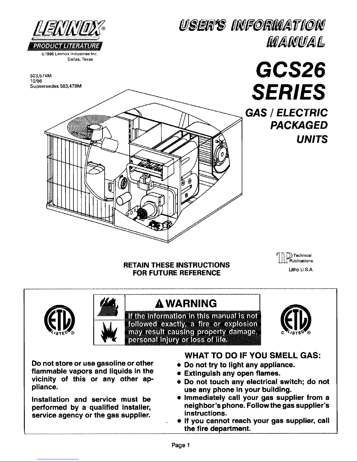
GCS26
SERIES
GAS / ELECTRIC
PACKAGED
UNITS
RETAIN THESE INSTRUCTIONS
FOR FUTURE REFERENCE
bllcattons
Litho US.A.
Do not store or use gasoline or other
flammable vapors and liquids in the
vicinity of this or any other ap-
pliance.
Installation and service must be
performed by a qualified installer,
service agency or the gas supplier.
A WARNING
c
WHAT TO DO IF YOU SMELL GAS:
• Do not try to light any appliance.
• Extinguish any open flames.
• Do not touch any electrical switch; do not
use any phone in your building.
• Immediately call your gas supplier from a
neighbor's phone. Follow the gas supplier's
instructions.
• If you cannot reach your gas supplier, call
the fire department.
Page 1
Page 2
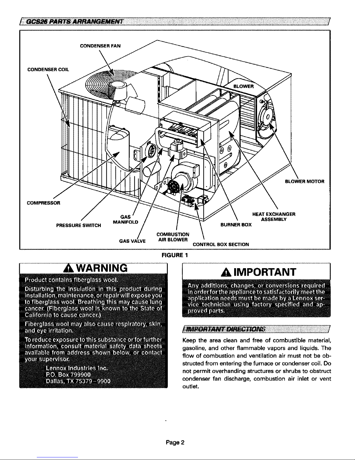
CONDENSERFAN
CONDENSER COIL
\
BLOWER MOTOR
COMPRESSOR
PRESSURESWITCH
GAS
HEAT EXCHANGER
ASSEMBLY
BURNER BOX
GAS VALVE
COMBUSTION
AIR BLOWER
CONTROL BOX SECTION
FIGURE 1
,& IMPORTANT
Keep the area clean and free of combustible material,
gasoline, and other flammable vapors and liquids. The
flow of combustion and ventilation air must not be ob-
structed from entering the furnace or condenser coil. Do
not permit overhanding structures or shrubs to obstruct
condenser fan discharge, combustion air inlet or vent
outlet.
Page 2
Page 3

FOR YOUR SAFETY READ BEFORE LIGHTING
BEFORE LIGHTING smell all around the appliance area for
gas. Be sure to smell next to the floor because some gas is
heavier than air and will settle on the floor.
ILWARNING
A ILWARNING
WARNING
WARNING
To place GCS26 unit into heating operation:
This appliance does not have a pilot. It is equipped
with anign ition system wh ich auto matically lights the
burner. Do not try to light by hand.
Gas Valve Operation (Figures 3 and 4)
1 - STOP! Read the safety information at the begin-
ning of this section.
2 - Set thermostat to lowest setting. See figure 2,
THERMOSTATS
FIGURE 2
3 - Turn off all electrical power to appliance.
4 - This appliance is equipped with an ignition device
which automatically lights the pilot. Do not try to
light the pilot by hand.
5 - Remove burner compartment access panel.
6 - On Honeywell VR8205 gas valves, turn knob on
gas valve clockwise 4_ to OFF. On Robertshaw
7200 gas valve, depress lever on gas control and
move to OFF and release. Do not force. Refer to
figures 3 and 4.
HONEYWELL VR8205 SERIES GAS VALVE
GAS VALVE SHOWN IN OFF POSITION
FIGURE 3
ROBERTSHAW 7200 GAS VALVE
GAS VALVE _ _*__ a _--J _
SELECTOR ARM
IN OFF
POSITION
RGURE 4
7 - Wait fifteen (15) minutes to clear out any gas. If
you then smell gas, STOPI Immediately call your
gassupplier from a neighbor's phone. Followthe
gas supplier's instructions. If you do not smell
gas go to next step.
8- On Honeywell VR8205 gas valves, turn knob on
gas valve counterclockwise 41_ to ON. On Robert-
shaw 7200 gas valve, depress lever on gas control
and move to ON and release.
9- Replace access panel.
10- Turn on all electrical power to unit.
11- Set thermostat to desired setting.
12- If the appliance still will not operate, follow the
instructions "To Turn Off Gas To Unit" and call
your service technician or gas supplier.
P_e3
Page 4

To Turn Off Gas To Unit
1 - Set thermostat to lowest setting.
2 - Turn off all electrical power to unit if service isto be
performed.
3 - Remove burner compartment access panel.
4 - On Honeywell VR8205 gas valves, turn knob on gas
valve clockwise41_ to OFF. Do not force. On Robert-
shaw 7200 gas valve, depress lever on gas control
and move to OFF and release.
5 - Replace access panel.
Not supplied. Inspect once a month.. Replace dispos-
able or clean permanent type as necessary, DO NOT re-
place permanent type with disposable.
Unit is equipped with an internal filter clip which is
located in indoor coil compartment attached to side of
the unit drain pan.
TABLE 1
GCS26 UNIT FILTER SIZE
GCS26 uNIT MODEL FALTERSIZE
-024, -030, -036 24" X 25"
-042 28" X 25"
-048 30" X 30"
Normal Maintenance
Periodic inspection and maintenance normally
consists of changing or cleaning filters and (under
some conditions) cleaning the main burners.
WARNING
A WARNING
NOTE - Care should be used when cleaning the coil so
that the coil fins are not damaged.
Do not permit the hot condenser air discharge to be ob-
structed by overhanging structures or shrubs.
Heating System Inspection
It is the owner's responsibility to insure that an annual
inspection of the entire heating portion of the unit is
made by a qualified service agency. This should in-
clude inspection of the burner, heat exchanger and flue
for any corrosion or soot accumulation which may re-
quire cleaning. The burner and controls should also be
checked for proper operation.
Vent Outlet
Visually inspect vent outlet periodically to make sure
that the buildup of soot and dirt is not excessive. If nec-
essary, clean to maintain adequate opening to dis-
charge flue products.
Burner Flame
The GCS26 burner flame is not adjustable; however,
the flame should be inspected at the beginning of each
heating season and burners should be cleaned, if nec-
essary. Burner flame should be blue when burning nat-
ural gas.
Venting System Inspection
Annually (before heating season) inspect furnace vent-
ing system, vent cap, heat exchanger and burners for
corrosion, deterioration, or deposits of debris. Remove
any obstructions.
Contact your Lennox dealer for a periodic unit inspec-
tion by a qualified service technician.
Rollout Safety Switch
Your GCS26 gas/electric unit is equipped with a roll-out
safety switch which shuts off the gas supply to the fur-
nace in case of heat exchanger blockage. If the heating
section ofthe unit fails to operate due to the functioning
of this safety switch, DO NOT attempt to place the unit
into operation. Contact a qualified service technician.
Motors
Indoor, outdoor fan and vent motors are permanently
lubricated and require no maintenance.
Outdoor Coil
Dirt and debris should not be allowed to accumulate on
the outdoor coil surface or other parts in the air circuit.
Cleaning should be as often as necessary to keep the
coil clean. Use a brush, vacuum cleaner attachment, or
other suitable means. If water is used to clean the coil,
be sure the power to unit is shut off prior to cleaning.
Call your service technician if unit is inoperative. Be-
fore calling, always check the following to be sure ser-
vice is required.
1 - Check that electrical disconnect switches are ON.
2 - Check room thermostat for proper setting.
3 - Replace any blown fuses or reset circuit breakers.
4 - Gas valve should be ON.
5 - Air filter should not be plugged limiting air flow.
6 - Is gas turned on at meter?
7 - Is manual main shut-off valve open?
To keep your Lennox gas heating system in peak operat-
ing condition year after year, contact your independent
Lennox dealer about a planned service program.
Page 4
 Loading...