

Page 1
Page 1
© 2008 Lennox Industries Inc.
Corp. 0804−L2
G71MPP
Service Literature
Revised 05−05−2008
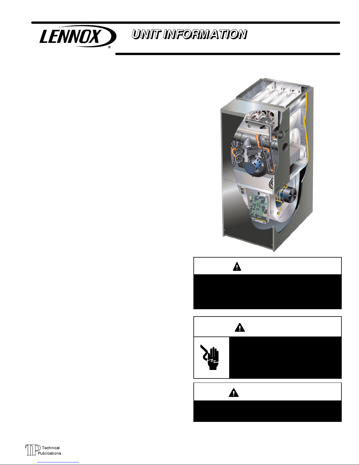
G71MPP SERIES UNITS
G71MPP series units are high−efficiency multi−position
(upflow, downflow, horizontal right and left) gas furnaces
equipped with variable capacity gas valve, variable speed
combustion air inducer and variable speed indoor blower
motor. All models are designed only for direct vent (dual
pipe) venting system. G71MPP units are available in heating capacities from 66,000 to 132,000 Btuh (19.3 to 38.6
kW) and cooling applications from 2 to 5 tons (7.0 kW to
17.5 kW). Refer to Engineering Handbook for proper sizing.
Units are factory equipped for use with natural gas. Kits are
available for conversion to LPG operation. G71MPP model
units are equipped with the Lennox SureLight
®
variable capacity integrated control. All G71MPP units meet the California Nitrogen Oxides (NO
x
) Standards and California Sea-
sonal Efficiency requirements.
All specifications in this manual are subject to change. Procedures outlined in this manual are presented as a recommendation only and do not supersede or replace local or
state codes. In the absence of local or state codes, the
guidelines and procedures outlined in this manual (except
where noted) are recommendations only and do not constitute code.
TABLE OF CONTENTS
Specifications Page 2. . . . . . . . . . . . . . . . . . . . . . . . . . . . .
Optional Accessories Page 3. . . . . . . . . . . . . . . . . . . . . .
Blower Data Page 4. . . . . . . . . . . . . . . . . . . . . . . . . . . . . .
I Unit Components Page 16. . . . . . . . . . . . . . . . . . . . . . .
Control Box 16. . . . . . . . . . . . . . . . . . . . . . . . . . . . . . . . .
Blower Compartment 28. . . . . . . . . . . . . . . . . . . . . . . . .
Heating Components 30. . . . . . . . . . . . . . . . . . . . . . . . .
II Installation Page 36. . . . . . . . . . . . . . . . . . . . . . . . . . . .
III Start Up Page 47. . . . . . . . . . . . . . . . . . . . . . . . . . . . . . .
IV Heating System Service Checks Page 48. . . . . . . . .
V Typical Operating Characteristics Page 51. . . . . . . . .
VI Maintenance Page 52. . . . . . . . . . . . . . . . . . . . . . . . . .
VII Wiring and Sequence of Operation Page 54. . . . . .
VIII Field Wiring Page 61. . . . . . . . . . . . . . . . . . . . . . . . .
WARNING
Improper installation, adjustment, alteration, service
or maintenance can cause property damage, personal injury or loss of life. Installation and service must
be performed by a licensed professional installer (or
equivalent), service agency or the gas supplier.
WARNING
Electric shock hazard. Can cause injury
or death. Before attempting to perform
any service or maintenance, turn the
electrical power to unit OFF at disconnect switch(es). Unit may have multiple
power supplies.
WARNING
Sharp edges.
Be careful when servicing unit to avoid sharp edges
which may result in personal injury.
Page 2

Page 2
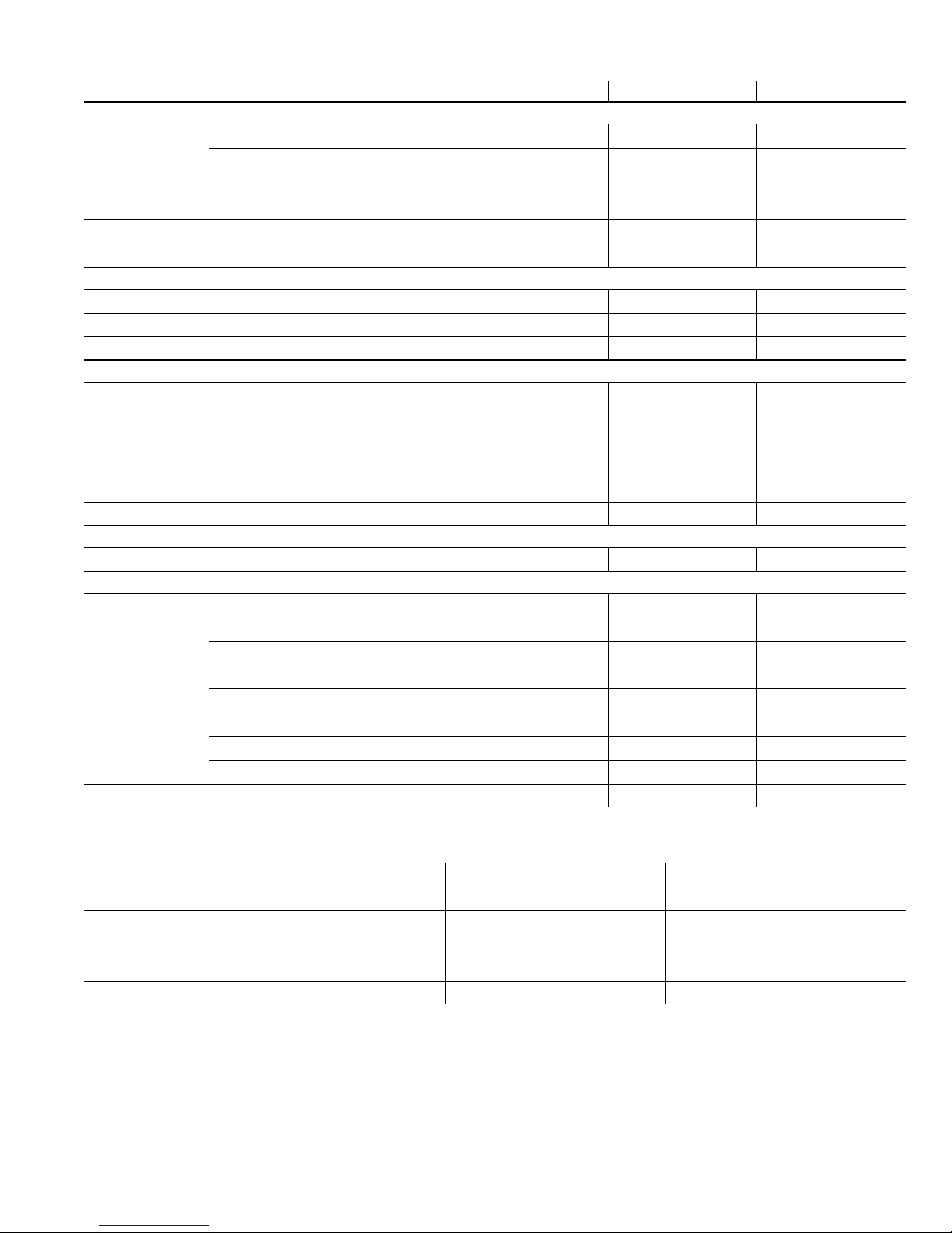
SPECIFICATIONS
Gas
Heating
Performance
ModelNo. G71MPP
−36B−070
G71MPP
−36C−090
G71MPP
−60C−090
G71MPP
−60C−110
G71MPP
−60D−135
Maximum
Input− Btuh 66,000 88,000 88,000 110,000 132,000
Output− Btuh 60,000 81,000 81,000 103,000 123,000
Temperature rise range − _F 50 − 80 60 − 90 50 − 80 50 − 80 55 − 85
Gas Manifold Pressure (in. w.g.)
Natural Gas / LPG/Propane
3.5 / 10.0 3.5 / 10.0 3.5 / 10.0 3.5 / 10.0 3.5 / 10.0
Minimum
Input − Btuh 26,000 35,000 35,000 44,000 53,000
Output − Btuh 25,000 34,000 34,000 42,000 51,000
Temperature rise range − _F 40 − 70 40 − 70 40 − 70 40 − 70 40 − 70
Gas Manifold Pressure (in. w.g.)
Natural Gas / LPG/Propane
0.7 / 2.0 0.7 / 2.0 0.7 / 2.0 0.7 / 2.0 0.7 / 2.0
1
AFUE 95.0% 95.0% 95.0% 95.0% 95.0%
Highstatic(CSA)− in.w.g. .80 .80 .80 .80 .80
Connections
in.
Intake / Exhaust Pipe (PVC) 2 / 2 2 / 2 2 / 2 2 / 2 3 / 3
Condensate Drain Trap (PVC pipe) − i.d. 1/2 1/2 1/2 1/2 1/2
with field supplied (PVC coupling) − o.d. 3/4 3/4 3/4 3/4 3/4
hose with hose clamp − i.d. x o.d. 1 x 1−1/4 1 x 1 1/4 1 x 1 1/4 1 x 1 1/4 1 x 1 1/4
GaspipesizeIPS 1/2 1/2 1/2 1/2 1/2
Indoor
Blower
Wheelnominaldiameter xwidth −in. 10 x 8 10 x 10 11−1/2 x 10 11−1/2 x 10 11−1/2 x 10
Motoroutput − hp 1/2 1/2 1 1 1
Tons ofadd−oncooling 2 − 3.5 2 − 3.5 3.5 − 5 3.5 − 5 3.5 − 5
Air volume range − cfm
250 −1395 250 − 1395
450 − 2215 450 − 2210 450 − 2190
ShippingData lbs. − 1 package 149 160 171 184 206
Electricalcharacteristics 120 volts − 60 hertz − 1 phase (less than 12 amps)
NOTE − Filters and provisions for mounting are not furnished and must be field provided.
1
Annual Fuel Utilization Efficiency based on DOE test procedures and according to FTC labeling regulations. Isolated combustion system rating for non−weatherized furnaces.
Page 3
Page 3
OPTIONAL ACCESSORIES
B" Width Models C" Width Models D" Width Models
FILTER KITS
1
Air Filter and
Rack Kit
Horizontal (end) Size of filter − in. 87L96 − 18 x 25 x 1 87L97 − 20 x 25 x 1 87L98 − 25 x 25 x 1
Side Return
Single 44J22 44J22 44J22
Ten Pack 66K63 66K63 66K63
Size of filter − in. 16 x 25 x 1 16 x 25 x 1 16 x 25 x 1
EZ Filter Base
Catalog No. − Ship. Wt. − lbs. 73P56 − 7 73P57 − 8 73P58 − 10
Size of field provided filter − in. 16 x 25 x 1 20 x 25 x 1 24 x 24 x 1
CABINET ACCESSORIES
Down−Flow Additive Base 11M60 11M61 11M62
Horizontal Support Frame Kit 56J18 56J18 56J18
Return Air Base 98M60 98M58 98M59
CONDENSATE DRAIN KITS
Condensate Drain Heat Cable
6 ft. 26K68 26K68 26K68
24 ft. 26K69 26K69 26K69
50 ft. 26K70 26K70 26K70
Heat Cable Tape
Fiberglass − 1/2 in. x 66 ft. 36G53 36G53 36G53
Aluminum foil − 2 in. x 60 ft. 16P89 16P89 16P89
Condensate Trap Alternate Location Kit − Up−Flow Only 76M20 76M20 76M20
CONTROLS
ComfortSenset 7000 Thermostat Y0349 Y0349 Y0349
TERMINATION KITS − See Installation Instructions for specific venting information.
Termination Kits Concentric
2 in. 71M80 69M29 − − −
3 in. − − − 60L46 60L46
Wall − Close Couple
2 in. 22G44 − − − − − −
3 in. 44J40 44J40 44J40
Close Couple 2 in. 30G28 − − − − − −
3 in. 81J20 81J20 81J20
Wall − Wall Ring Kit 2 in. 15F74 15F74 − − −
Roof 2 in. 15F75 15F75 − − −
Roof Termination Flashing Kit − Contains two flashings. 44J41 44J41 44J41
1
Cleanable polyurethane frame type filter.
GAS HEAT ACCESSORIES
Input
High Altitude Pressure Switch Kit LPG/Propane Kit LPG/Propane to Natural Gas Kit
7501−10,000 ft. 0−10,000 ft. 0−10,000 ft.
−070 36W77 33W41 33W42
−090 40W05 33W41 33W42
−110 40W06 33W41 33W42
−135 40W07 33W41 33W42
Page 4
Page 4
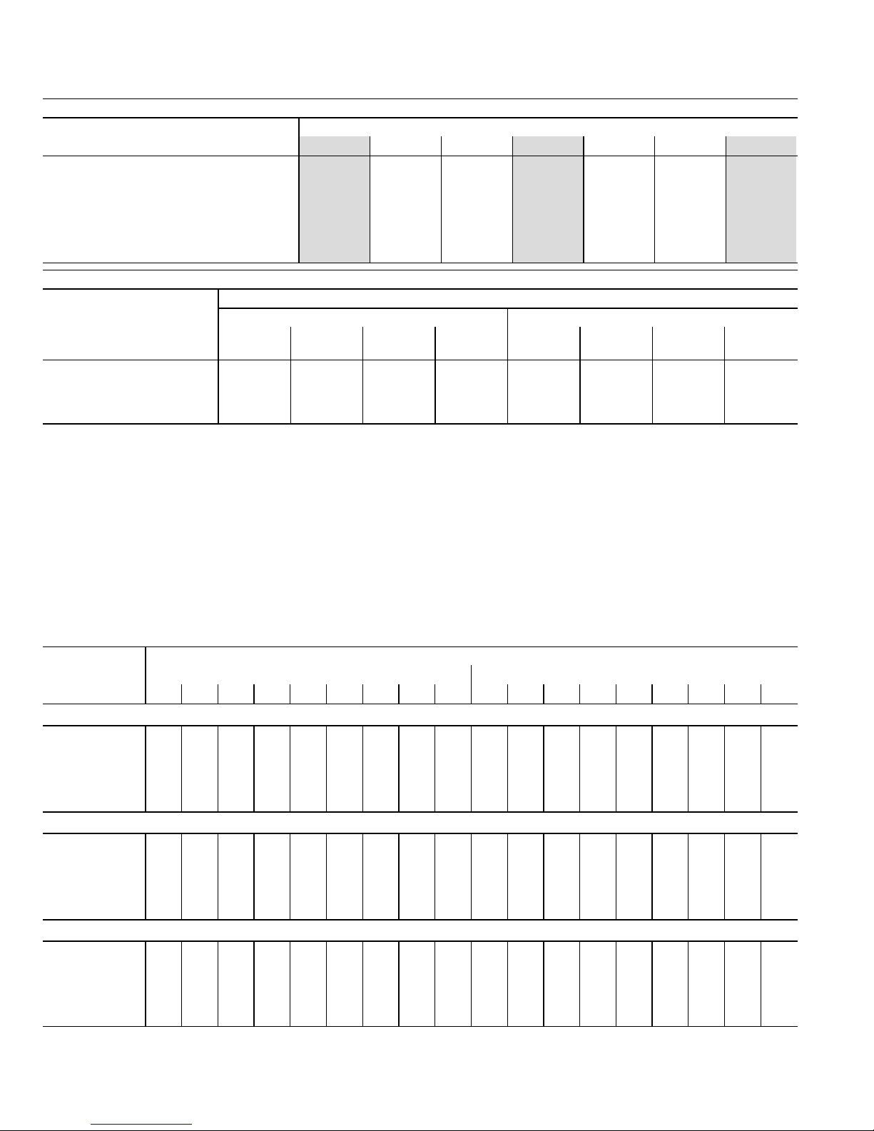
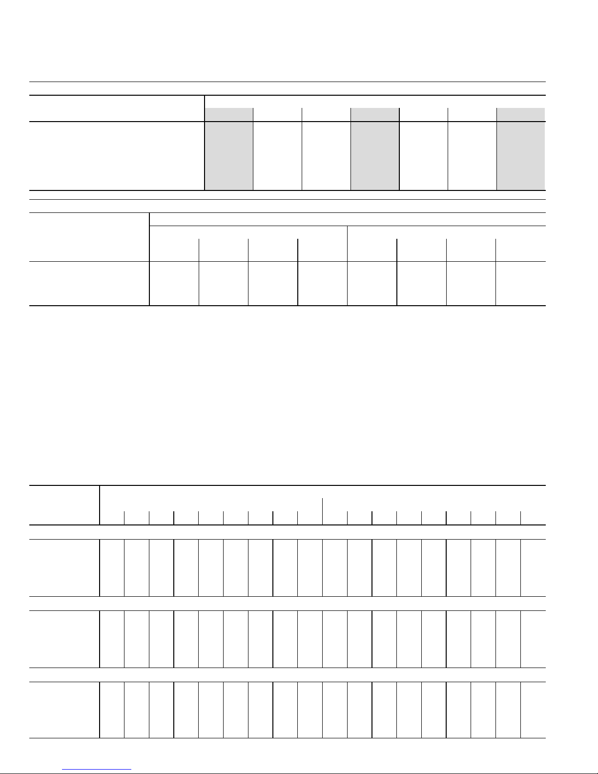
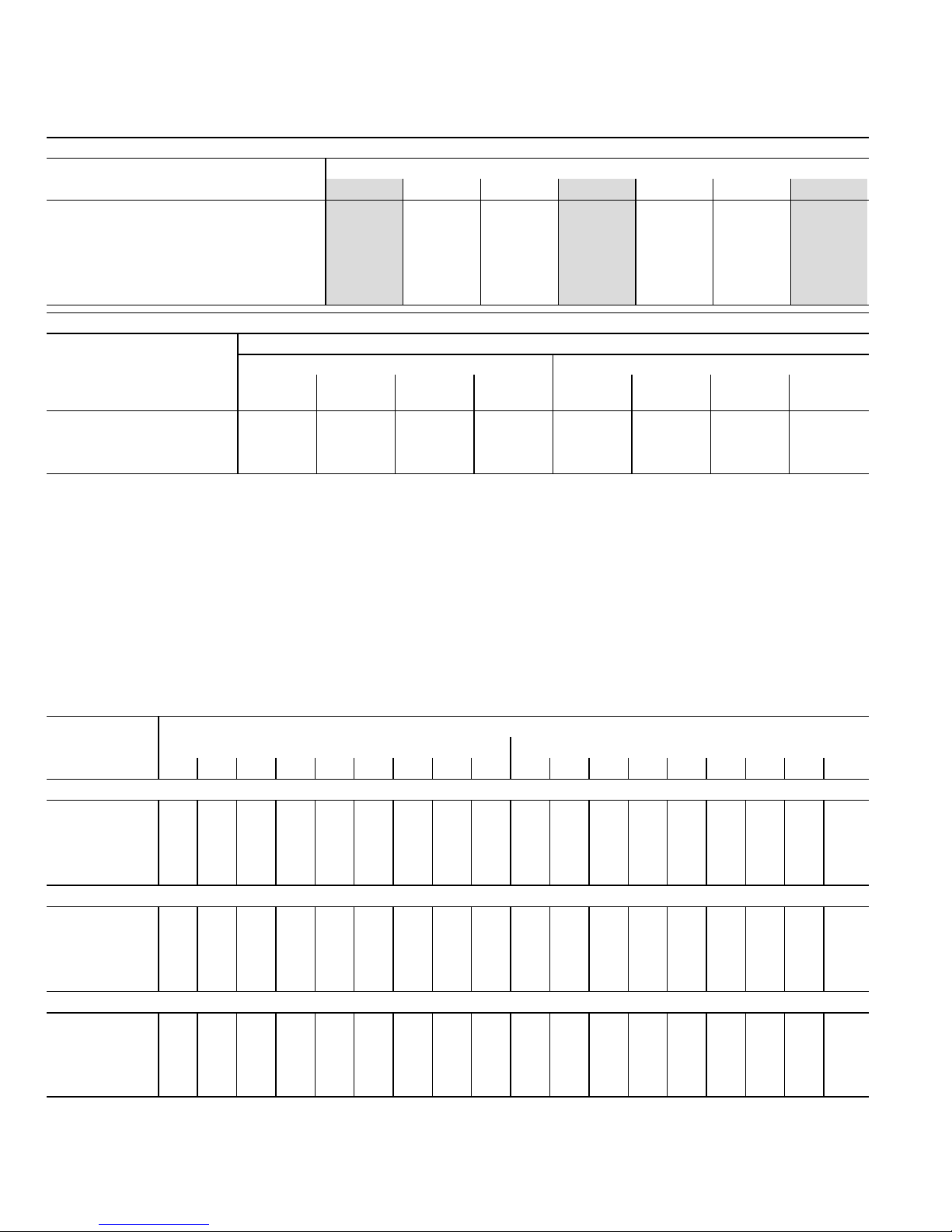
TABLE 1
G71MPP−36B−070 BLOWER PERFORMANCE (less filter)
0 through 0.80 in. w.g. External Static Pressure Range
HEATING BLOWER PERFORMANCE
Heating Adjust CFM Selections
Heating Input Range and Blower Volume − CFM
40% 50% 60% 70% 80% 90% 100%
Increase (+15%) Heat CFM 535 610 690 770 870 975 1075
Increase (+7.5%) Heat CFM 505 575 645 720 810 905 1000
Default Heat CFM 480 545 610 675 760 845 930
Decrease (–7.5% ) Heat CFM 460 520 580 640 715 790 870
Decrease (–15% ) Heat CFM 440 490 540 590 655 715 780
COOLING BLOWER PERFORMANCE
Cooling Adjust CFM
Selections
Blower Speed Selections
First Stage Cool Speed − cfm Second Stage Cool Speed − cfm
Low
Medium−
Low
Medium
High
High
(Default)
Low
Medium−
Low
Medium
High
High
(Default)
Increase (+10%) Cool CFM 730 815 865 935 1015 1190 1280 1395
Default Cool CFM 680 755 795 855 930 1065 1155 1270
Decrease (–10%) Cool CFM 625 695 730 775 830 950 1010 1105
The effect of static pressure is included in air volumes shown.
Lennox Harmony IIIt Zone Control Applications − Minimum blower speed is 250 cfm.
The following control board configurations are available. See Installation Instructions for details and DIP switch settings.
Heat Mode (Heating Blower Performance Table):
With a single−stage thermostat, furnace will operate at three, staged rates (40/70/100%) with a time delay between each stage (values in grey−shaded
columns).
With two−stage thermostat there are two modes available.
Traditional two−stage mode − W1 demand results in 70% firing rate. W2 results in 100% firing rate. No delay between stages. (values shown in 70%
and 100% grey−shaded columns only).
Variable Rate Capacity Mode − furnace automatically adjusts firing rate based on first− and second−stage cycle times. (all columns)
Cool Mode (Cooling Blower Performance table):
First stage COOL (two−stage air conditioning units only) is approximately 70% of the same second stage COOL speed position.
Continuous Fan speeds are approximately 28%, 38%, 70% and 100% (DIP switch selectable) of the same second−stage COOL speed position
minimum 250 cfm.
G71MPP−36B−070 BLOWER MOTOR WATTS − COOLING
Blower Speed
Options
Motor Watts @ Various External Static Pressures − in. wg.
First Stage Second Stage
0 0.10 0.20 0.30 0.40 0.50 0.60 0.70 0.80 0 0.10 0.20 0.30 0.40 0.50 0.60 0.70 0.80
Increase (+10%) Cool CFM
Low 55 70 90 110 130 145 160 175 190 135 155 175 200 220 245 270 295 320
Medium−Low 75 90 110 130 150 170 190 205 220 185 215 250 285 315 345 370 395 420
Medium−High 85 100 120 145 165 185 205 225 250 235 265 300 335 370 400 425 455 480
High 105 125 150 170 190 210 235 255 280 315 340 370 395 440 480 510 540 570
Default Cool CFM
Low 45 60 80 95 115 130 145 160 175 100 120 140 165 190 215 235 255 275
Medium−Low 60 75 95 110 130 145 165 180 200 140 165 190 220 245 265 290 315 340
Medium−High 65 85 105 125 140 155 175 195 215 175 200 230 260 285 310 340 365 390
High 85 100 120 140 160 180 200 220 240 230 260 295 325 360 390 410 435 455
Decrease (–10%) Cool CFM
Low 40 55 70 85 100 120 130 145 160 75 90 110 125 150 175 190 210 225
Medium−Low 45 60 80 95 115 135 145 160 175 95 120 150 175 200 220 240 260 285
Medium−High 50 65 85 105 125 145 160 175 190 125 150 175 195 220 240 265 290 320
High 60 75 95 115 135 150 170 190 215 165 190 215 245 265 485 315 340 370
Page 5
Page 5
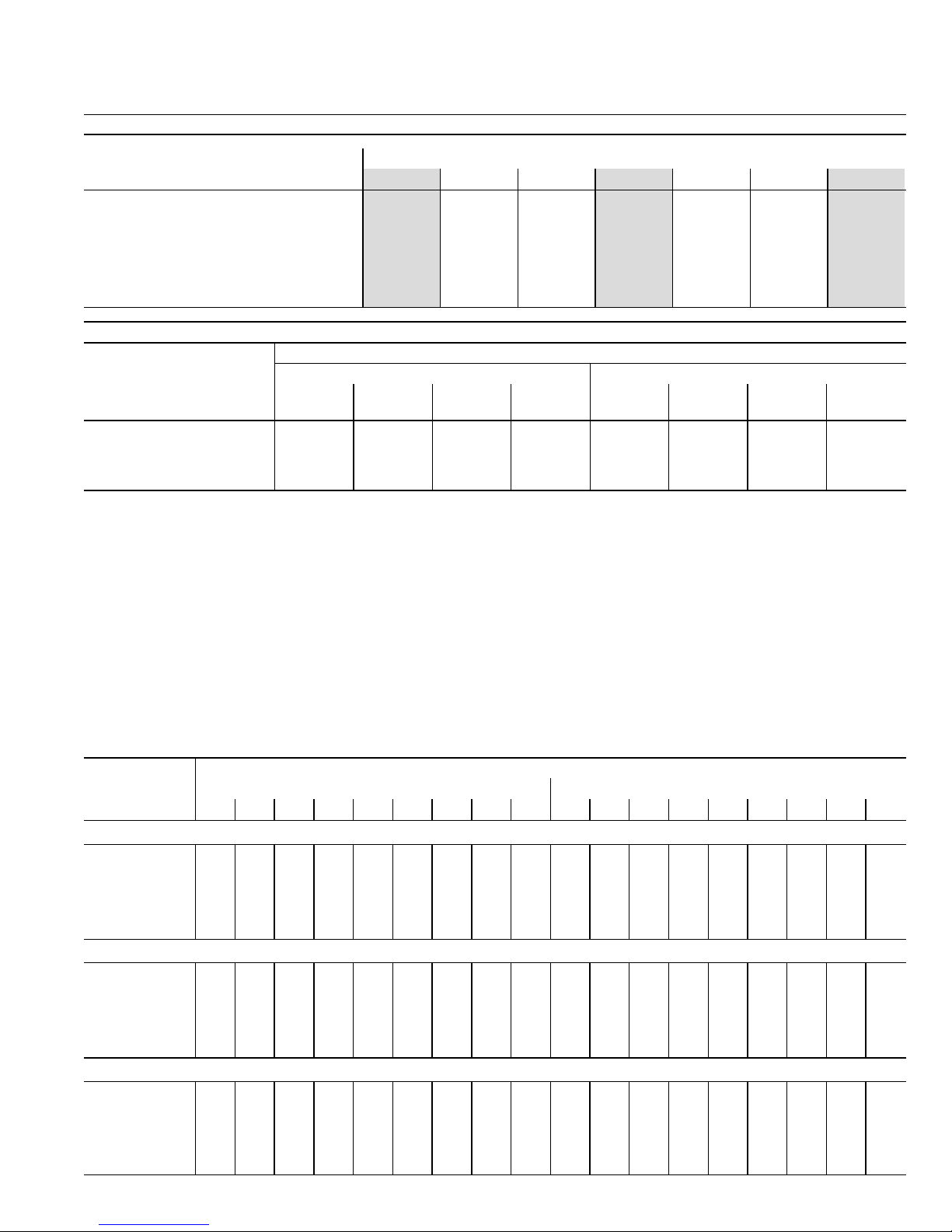
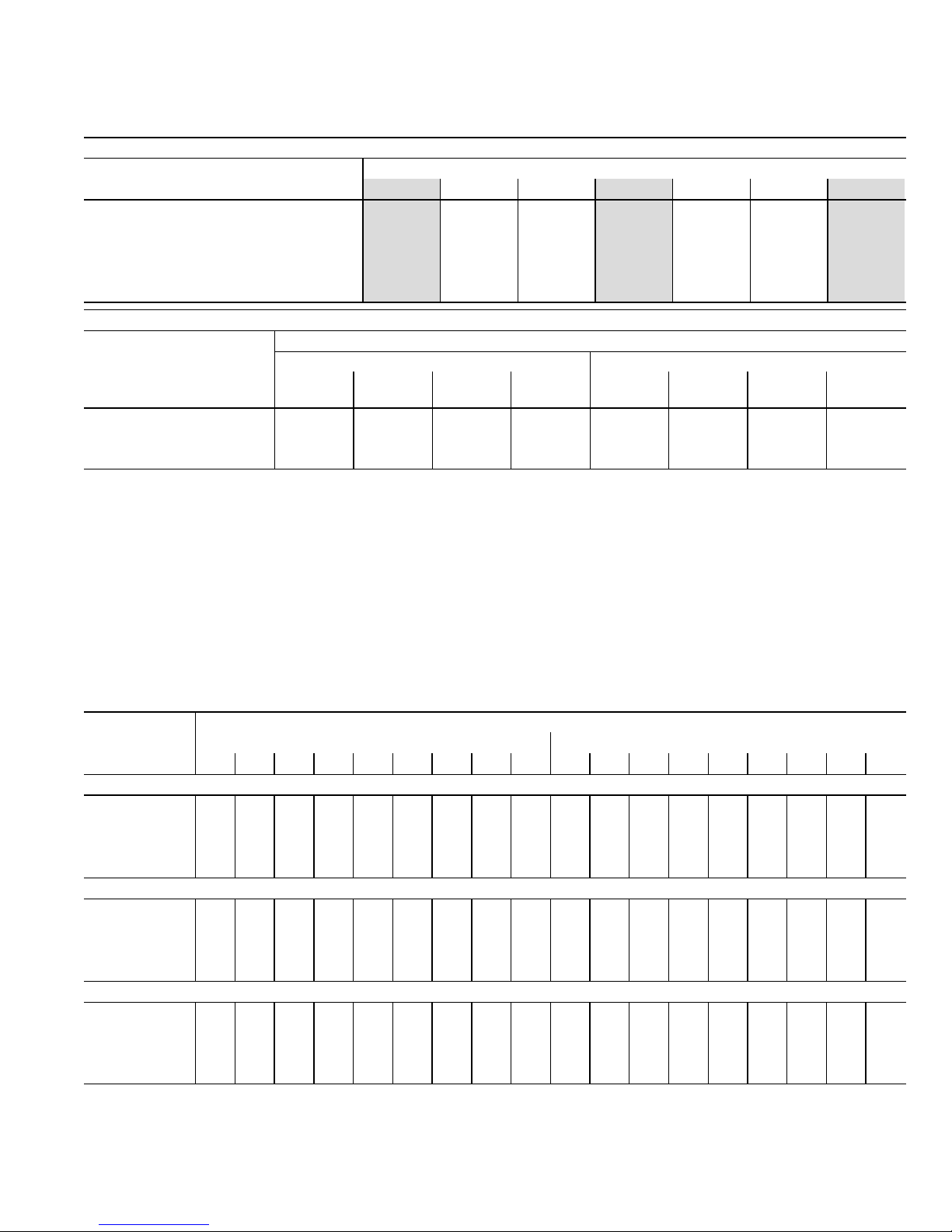
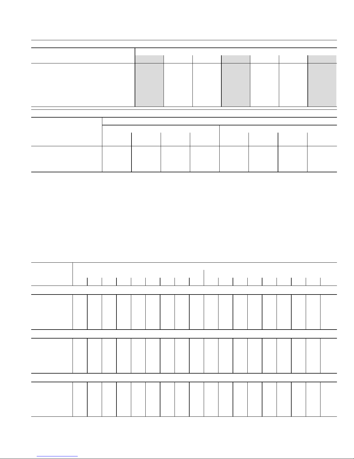
TABLE 2
G71MPP−36C−090 BLOWER PERFORMANCE (less filter)
0 through 0.80 in. w.g. External Static Pressure Range
HEATING BLOWER PERFORMANCE
Heating Adjust CFM Selections
Heating Input Range and Blower Volume − CFM
40% 50% 60% 70% 80% 90% 100%
Increase (+15%) Heat CFM 650 740 825 910 1005 1100 1200
Increase (+7.5%) Heat CFM 620 695 775 850 940 1025 1115
Default Heat CFM 590 655 725 790 870 950 1030
Decrease (–7.5% ) Heat CFM 555 615 680 740 815 890 965
Decrease (–15% ) Heat CFM 525 575 630 680 745 805 870
COOLING BLOWER PERFORMANCE
Cooling Adjust CFM
Selections
Blower Speed Selections
First Stage Cool Speed − cfm Second Stage Cool Speed − cfm
Low
Medium−
Low
Medium
High
High
(Default)
Low
Medium−
Low
Medium
High
High
(Default)
Increase (+10%) Cool CFM 705 790 845 920 1020 1185 1275 1395
Default Cool CFM 650 730 770 830 905 1060 1145 1270
Decrease (–10%) Cool CFM 600 670 705 750 800 925 1010 1100
The effect of static pressure is included in air volumes shown.
Lennox Harmony IIIt Zone Control Applications − Minimum blower speed is 250 cfm.
The following control board configurations are available. See Installation Instructions for details and DIP switch settings.
Heat Mode (Heating Blower Performance Table):
With a single−stage thermostat, furnace will operate at three, staged rates (40/70/100%) with a time delay between each stage (values in grey−shaded
columns).
With two−stage thermostat there are two modes available.
Traditional two−stage mode − W1 demand results in 70% firing rate. W2 results in 100% firing rate. No delay between stages. (values shown in 70%
and 100% grey−shaded columns only).
Variable Rate Capacity Mode − furnace automatically adjusts firing rate based on first− and second−stage cycle times. (all columns)
Cool Mode (Cooling Blower Performance table):
First stage COOL (two−stage air conditioning units only) is approximately 70% of the same second stage COOL speed position.
Continuous Fan speeds are approximately 28%, 38%, 70% and 100% (DIP switch selectable) of the same second−stage COOL speed position
minimum 250 cfm.
G71MPP−36C−090 BLOWER MOTOR WATTS − COOLING
Blower Speed
Options
Motor Watts @ Various External Static Pressures − in. wg.
First Stage Second Stage
0 0.10 0.20 0.30 0.40 0.50 0.60 0.70 0.80 0 0.10 0.20 0.30 0.40 0.50 0.60 0.70 0.80
Increase (+10%) Cool CFM
Low 35 50 70 90 105 125 140 160 175 85 110 135 160 185 205 235 265 295
Medium−Low 45 60 80 100 125 150 170 185 205 125 155 185 220 245 275 305 330 360
Medium−High 60 75 95 110 135 160 180 200 220 165 195 230 265 300 330 355 380 410
High 65 85 110 135 160 180 205 225 245 210 245 285 325 360 390 425 460 495
Default Cool CFM
Low 35 45 60 75 95 115 130 145 160 60 80 110 135 155 175 195 215 235
Medium−Low 40 55 70 90 110 130 150 165 185 105 125 145 170 200 225 250 270 295
Medium−High 45 60 80 95 115 135 155 175 195 11 5 140 175 205 235 265 290 315 335
High 50 65 85 105 130 155 180 200 220 155 185 220 255 285 315 345 380 415
Decrease (–10%) Cool CFM
Low 30 40 55 75 90 105 120 135 150 55 65 85 105 125 150 170 190 210
Medium−Low 40 50 65 80 100 120 130 145 160 65 90 120 145 165 185 205 225 250
Medium−High 40 55 70 90 105 125 140 160 180 85 105 135 165 185 210 235 260 285
High 45 60 75 90 115 135 155 170 190 105 125 150 175 210 240 275 305 335
Page 6
Page 6
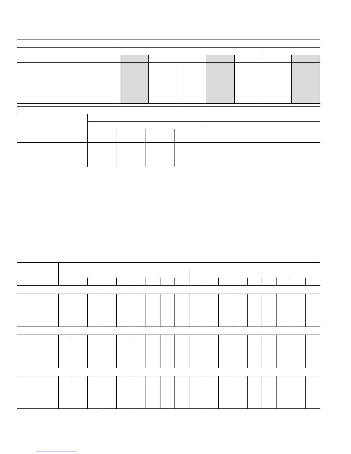
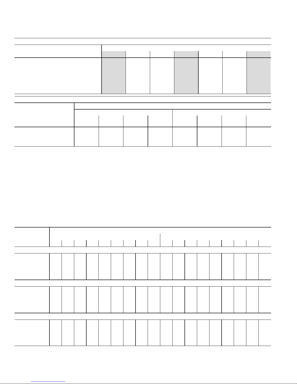
TABLE 3
G71MPP−60C−090 BLOWER PERFORMANCE (less filter)
Bottom Return Air, Return Air from Both Sides or Return Air from Bottom and One Side
0 through 0.80 in. w.g. External Static Pressure Range
HEATING BLOWER PERFORMANCE
Heating Adjust CFM Selections
Heating Input Range and Blower Volume − CFM
40% 50% 60% 70% 80% 90% 100%
Increase (+15%) Heat CFM 665 800 935 1070 1205 1335 1470
Increase (+7.5%) Heat CFM 600 730 860 990 111 0 1235 1355
Default Heat CFM 615 715 820 920 1035 1150 1265
Decrease (–7.5% ) Heat CFM 520 630 740 850 960 1070 1180
Decrease (–15% ) Heat CFM 465 565 665 765 870 970 1075
COOLING BLOWER PERFORMANCE
Cooling Adjust CFM
Selections
Blower Speed Selections
First Stage Cool Speed − cfm Second Stage Cool Speed − cfm
Low
Medium−
Low
Medium
High
High
(Default)
Low
Medium−
Low
Medium
High
High
(Default)
Increase (+10%) Cool CFM 1105 1185 1355 1545 1605 1710 1925 2165
Default Cool CFM 995 1080 1205 1345 1440 1560 1755 1960
Decrease (–10%) Cool CFM 890 960 1090 1215 1275 1380 1590 1755
The effect of static pressure is included in air volumes shown.
Lennox Harmony IIIt Zone Control Applications − Minimum blower speed is 450 cfm.
The following control board configurations are available. See Installation Instructions for details and DIP switch settings.
Heat Mode (Heating Blower Performance Table):
With a single−stage thermostat, furnace will operate at three, staged rates (40/70/100%) with a time delay between each stage (values in grey−shaded
columns).
With two−stage thermostat there are two modes available.
Traditional two−stage mode − W1 demand results in 70% firing rate. W2 results in 100% firing rate. No delay between stages. (values shown in 70%
and 100% grey−shaded columns only).
Variable Rate Capacity Mode − furnace automatically adjusts firing rate based on first− and second−stage cycle times. (all columns)
Cool Mode (Cooling Blower Performance table):
First stage COOL (two−stage air conditioning units only) is approximately 70% of the same second stage COOL speed position.
Continuous Fan speeds are approximately 28%, 38%, 70% and 100% (DIP switch selectable) of the same second−stage COOL speed position
minimum 450 cfm.
G71MPP−60C−090 BLOWER MOTOR WATTS − COOLING
Bottom Return Air, Return Air from Both Sides or Return Air from Bottom and One Side
Blower Speed
Options
Motor Watts @ Various External Static Pressures − in. wg.
First Stage Second Stage
0 0.10 0.20 0.30 0.40 0.50 0.60 0.70 0.80 0 0.10 0.20 0.30 0.40 0.50 0.60 0.70 0.80
Increase (+10%) Cool CFM
Low 115 135 160 185 205 230 255 275 300 305 340 375 410 440 475 505 535 565
Medium−Low 145 165 190 215 240 265 285 305 325 355 390 430 470 510 550 580 610 635
Medium−High 170 200 240 275 305 335 370 400 430 510 555 600 645 690 730 765 795 830
High 265 295 330 365 400 435 465 500 535 725 780 835 895 935 975 1005 1035 1065
Default Cool CFM
Low 90 110 130 155 175 195 215 235 255 220 250 285 320 350 385 415 450 485
Medium−Low 110 130 155 180 200 220 245 265 285 270 305 345 385 420 455 485 515 545
Medium−High 145 165 190 215 245 270 295 320 340 390 425 465 500 540 580 610 640 670
High 180 205 240 270 300 330 365 395 430 540 580 625 670 710 755 795 830 870
Decrease (–10%) Cool CFM
Low 70 85 105 125 145 165 185 205 225 160 190 220 255 275 300 330 360 390
Medium−Low 80 100 120 140 165 190 210 225 245 195 225 260 295 325 350 385 415 450
Medium−High 110 130 160 185 205 225 250 275 300 295 330 365 400 430 460 495 535 570
High 155 175 195 220 245 270 295 315 340 400 435 470 510 545 585 610 640 665
Page 7
Page 7
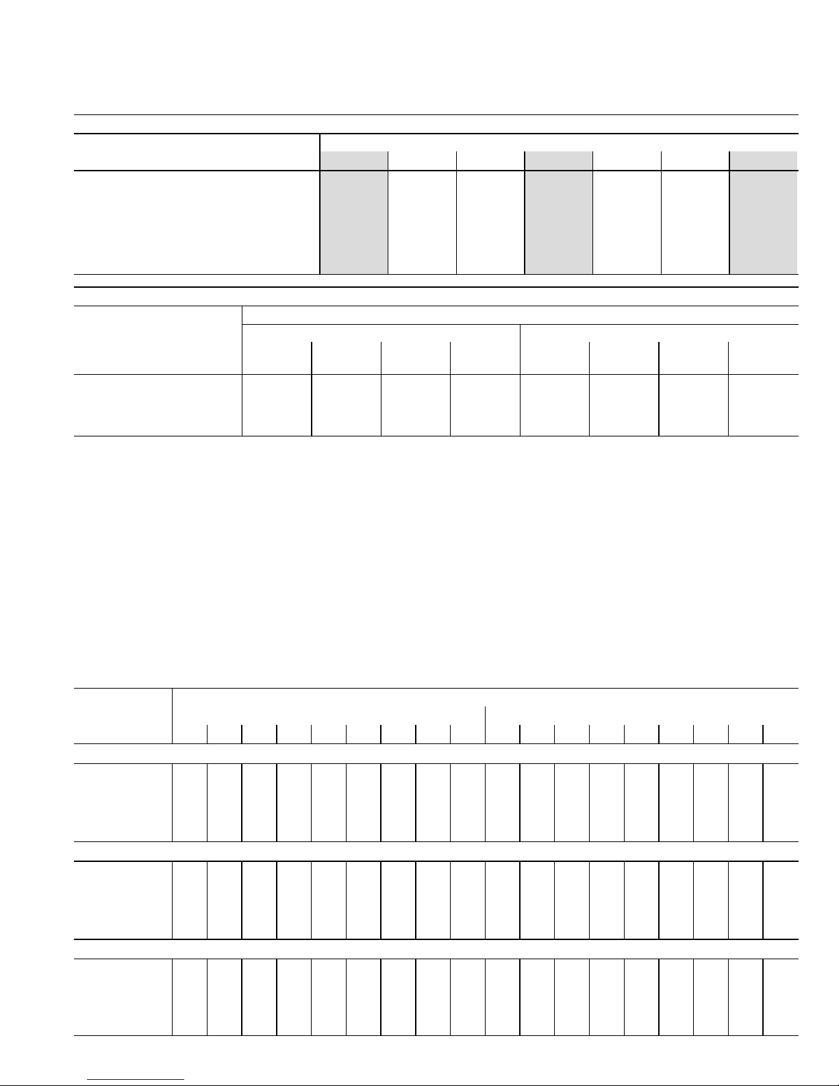
TABLE 4
G71MPP−60C−090 BLOWER PERFORMANCE (less filter) −− Single Side Return Air
(Air volumes in bold require field fabricated transition to accommodate 20 x 25 x 1 in. cleanable air filter
in order to maintain proper air velocity across the filter.)
0 through 0.80 in. w.g. External Static Pressure Range
HEATING BLOWER PERFORMANCE
Heating Adjust CFM Selections
Heating Input Range and Blower Volume − CFM
40% 50% 60% 70% 80% 90% 100%
Increase (+15%) Heat CFM 655 790 920 1050 1180 1310 1440
Increase (+7.5%) Heat CFM 605 725 850 970 1090 1205 1325
Default Heat CFM 555 675 790 905 1015 1125 1235
Decrease (–7.5% ) Heat CFM 515 625 730 835 940 1045 1150
Decrease (–15% ) Heat CFM 465 565 665 765 860 960 1055
COOLING BLOWER PERFORMANCE
Cooling Adjust CFM
Selections
Blower Speed Selections
First Stage Cool Speed − cfm Second Stage Cool Speed − cfm
Low
Medium−
Low
Medium
High
High
(Default)
Low
Medium−
Low
Medium
High
High
(Default)
Increase (+10%) Cool CFM 1080 1160 1315 1490 1575 1690 1895 2135
Default Cool CFM 985 1060 1185 1330 1405 1530 1735 1935
Decrease (–10%) Cool CFM 865 930 1065 1185 1250 1355 1560 1735
The effect of static pressure is included in air volumes shown.
Lennox Harmony IIIt Zone Control Applications − Minimum blower speed is 450 cfm.
The following control board configurations are available. See Installation Instructions for details and DIP switch settings.
Heat Mode (Heating Blower Performance Table):
With a single−stage thermostat, furnace will operate at three, staged rates (40/70/100%) with a time delay between each stage (values in grey−shaded
columns).
With two−stage thermostat there are two modes available.
Traditional two−stage mode − W1 demand results in 70% firing rate. W2 results in 100% firing rate. No delay between stages. (values shown in 70%
and 100% grey−shaded columns only).
Variable Rate Capacity Mode − furnace automatically adjusts firing rate based on first− and second−stage cycle times. (all columns)
Cool Mode (Cooling Blower Performance table):
First stage COOL (two−stage air conditioning units only) is approximately 70% of the same second stage COOL speed position.
Continuous Fan speeds are approximately 28%, 38%, 70% and 100% (DIP switch selectable) of the same second−stage COOL speed position
minimum 450 cfm.
G71MPP−60C−090 BLOWER MOTOR WATTS − COOLING
Blower Speed
Options
Motor Watts @ Various External Static Pressures − in. wg.
First Stage Second Stage
0 0.10 0.20 0.30 0.40 0.50 0.60 0.70 0.80 0 0.10 0.20 0.30 0.40 0.50 0.60 0.70 0.80
Increase (+10%) Cool CFM
Low 110 130 155 180 205 225 245 270 290 285 320 355 390 430 465 500 535 565
Medium−Low 125 150 175 205 225 250 275 300 325 355 390 430 470 500 530 570 605 645
Medium−High 170 195 230 260 290 325 355 385 415 515 550 590 625 670 710 750 795 840
High 240 275 315 355 380 405 445 485 525 740 785 835 885 920 955 990 1020 1050
Default Cool CFM
Low 85 100 125 145 170 200 215 235 255 200 230 270 310 340 370 400 430 460
Medium−Low 105 125 150 170 195 220 240 260 280 260 295 330 365 400 440 470 500 530
Medium−High 135 160 185 215 240 270 290 315 335 410 440 470 500 540 580 610 640 670
High 170 200 235 265 305 340 365 390 415 550 585 620 655 695 740 780 825 865
Decrease (–10%) Cool CFM
Low 65 80 100 120 140 160 180 205 225 180 215 245 265 290 320 345 375 445
Medium−Low 75 90 110 130 155 180 200 220 245 220 250 275 305 335 370 400 430 510
Medium−High 100 120 150 175 200 220 245 265 290 320 350 385 415 445 485 520 560 635
High 135 160 185 215 240 265 290 315 335 435 465 495 540 585 610 640 665 765
Page 8
Page 8
TABLE 5
G71MPP−60C−090 BLOWER PERFORMANCE (less filter) −− Side Return Air with Optional RAB Return Air Base
0 through 0.80 in. w.g. External Static Pressure Range
HEATING BLOWER PERFORMANCE
Heating Adjust CFM Selections
Heating Input Range and Blower Volume − CFM
40% 50% 60% 70% 80% 90% 100%
Increase (+15%) Heat CFM 645 770 895 1020 1155 1290 1425
Increase (+7.5%) Heat CFM 595 710 825 945 1070 1195 1315
Default Heat CFM 545 660 775 890 1005 1115 1225
Decrease (–7.5% ) Heat CFM 505 605 710 810 920 1030 1140
Decrease (–15% ) Heat CFM 455 555 650 750 845 945 1045
COOLING BLOWER PERFORMANCE
Cooling Adjust CFM
Selections
Blower Speed Selections
First Stage Cool Speed − cfm Second Stage Cool Speed − cfm
Low
Medium−
Low
Medium
High
High
(Default)
Low
Medium−
Low
Medium
High
High
(Default)
Increase (+10%) Cool CFM 1060 1135 1285 1455 1525 1655 1860 2100
Default Cool CFM 960 1035 1165 1310 1385 1500 1695 1905
Decrease (–10%) Cool CFM 865 920 1050 1165 1240 1320 1510 1695
The effect of static pressure is included in air volumes shown.
Lennox Harmony IIIt Zone Control Applications − Minimum blower speed is 450 cfm.
The following control board configurations are available. See Installation Instructions for details and DIP switch settings.
Heat Mode (Heating Blower Performance Table):
With a single−stage thermostat, furnace will operate at three, staged rates (40/70/100%) with a time delay between each stage (values in grey−shaded
columns).
With two−stage thermostat there are two modes available.
Traditional two−stage mode − W1 demand results in 70% firing rate. W2 results in 100% firing rate. No delay between stages. (values shown in 70%
and 100% grey−shaded columns only).
Variable Rate Capacity Mode − furnace automatically adjusts firing rate based on first− and second−stage cycle times. (all columns)
Cool Mode (Cooling Blower Performance table):
First stage COOL (two−stage air conditioning units only) is approximately 70% of the same second stage COOL speed position.
Continuous Fan speeds are approximately 28%, 38%, 70% and 100% (DIP switch selectable) of the same second−stage COOL speed position
minimum 450 cfm.
G71MPP−60C−090 BLOWER MOTOR WATTS − COOLING
Side Return Air with Optional RAB Return Air Base
Blower Speed
Options
Motor Watts @ Various External Static Pressures − in. wg.
First Stage Second Stage
0 0.10 0.20 0.30 0.40 0.50 0.60 0.70 0.80 0 0.10 0.20 0.30 0.40 0.50 0.60 0.70 0.80
Increase (+10%) Cool CFM
Low 110 130 150 175 195 215 240 265 290 275 305 340 380 410 440 470 505 540
Medium−Low 130 155 175 200 220 245 265 290 315 360 390 420 455 485 515 550 590 625
Medium−High 160 190 220 255 280 305 335 360 390 490 530 570 610 645 680 715 750 785
High 220 255 295 330 365 400 430 460 490 695 750 805 855 895 935 965 995 1025
Default Cool CFM
Low 80 95 120 140 165 190 210 235 255 190 225 265 305 330 355 390 420 455
Medium−Low 100 120 140 165 190 215 235 255 275 265 295 325 355 390 420 455 495 530
Medium−High 140 160 185 205 235 260 285 305 325 375 410 440 475 500 530 570 610 650
High 180 205 240 270 300 325 350 380 405 520 560 605 645 685 720 760 805 845
Decrease (–10%) Cool CFM
Low 70 85 105 125 140 160 180 200 220 155 175 200 225 255 290 315 340 365
Medium−Low 80 95 115 135 155 175 200 220 245 185 210 235 260 295 325 355 385 415
Medium−High 105 125 150 175 200 220 240 265 290 255 290 330 365 400 430 460 490 520
High 135 160 185 215 235 260 285 305 330 370 400 440 475 505 530 565 600 635
Page 9
Page 9
TABLE 6
G71MPP−60C−110 BLOWER PERFORMANCE (less filter)
Bottom Return Air, Return Air from Both Sides or Return Air from Bottom and One Side
0 through 0.80 in. w.g. External Static Pressure Range
HEATING BLOWER PERFORMANCE
Heating Adjust CFM Selections
Heating Input Range and Blower Volume − CFM
40% 50% 60% 70% 80% 90% 100%
Increase (+15%) Heat CFM 890 1050 1215 1375 1535 1695 1855
Increase (+7.5%) Heat CFM 845 975 1125 1275 1430 1585 1740
Default Heat CFM 800 960 1075 1190 1335 1480 1625
Decrease (–7.5% ) Heat CFM 735 860 990 1120 1250 1380 1510
Decrease (–15% ) Heat CFM 670 790 910 1030 1145 1260 1375
COOLING BLOWER PERFORMANCE
Cooling Adjust CFM
Selections
Blower Speed Selections
First Stage Cool Speed − cfm Second Stage Cool Speed − cfm
Low
Medium−
Low
Medium
High
High
(Default)
Low
Medium−
Low
Medium
High
High
(Default)
Increase (+10%) Cool CFM 945 1020 1160 1300 1625 1745 1990 2210
Default Cool CFM 840 910 1055 1180 1465 1580 1790 1995
Decrease (–10%) Cool CFM 740 800 920 1045 1290 1405 1605 1790
The effect of static pressure is included in air volumes shown.
Lennox Harmony IIIt Zone Control Applications − Minimum blower speed is 450 cfm.
The following control board configurations are available. See Installation Instructions for details and DIP switch settings.
Heat Mode (Heating Blower Performance Table):
With a single−stage thermostat, furnace will operate at three, staged rates (40/70/100%) with a time delay between each stage (values in grey−shaded
columns).
With two−stage thermostat there are two modes available.
Traditional two−stage mode − W1 demand results in 70% firing rate. W2 results in 100% firing rate. No delay between stages. (values shown in 70%
and 100% grey−shaded columns only).
Variable Rate Capacity Mode − furnace automatically adjusts firing rate based on first− and second−stage cycle times. (all columns)
Cool Mode (Cooling Blower Performance table):
First stage COOL (two−stage air conditioning units only) is approximately 70% of the same second stage COOL speed position.
Continuous Fan speeds are approximately 28%, 38%, 70% and 100% (DIP switch selectable) of the same second−stage COOL speed position
minimum 450 cfm.
G71MPP−60C−110 BLOWER MOTOR WATTS − COOLING
Bottom Return Air, Return Air from Both Sides or Return Air from Bottom and One Side
Blower Speed
Options
Motor Watts @ Various External Static Pressures − in. wg.
First Stage Second Stage
0 0.10 0.20 0.30 0.40 0.50 0.60 0.70 0.80 0 0.10 0.20 0.30 0.40 0.50 0.60 0.70 0.80
Increase (+10%) Cool CFM
Low 75 90 115 135 160 180 200 220 240 280 315 350 390 430 475 510 550 585
Medium−Low 90 105 130 150 175 200 220 245 270 340 380 425 465 505 545 575 610 645
Medium−High 120 140 170 195 225 250 275 300 330 510 545 585 620 675 735 770 805 840
High 160 185 210 235 265 290 325 360 395 710 755 805 855 905 950 980 1010 1035
Default Cool CFM
Low 55 70 90 110 135 155 175 195 215 205 235 275 310 345 380 415 450 485
Medium−Low 75 90 105 125 150 170 190 215 235 250 285 325 360 400 440 470 505 540
Medium−High 95 115 135 160 190 220 240 265 285 375 410 445 485 530 575 605 635 670
High 125 150 175 200 225 255 280 305 335 510 550 595 640 685 725 770 815 860
Decrease (–10%) Cool CFM
Low 45 60 80 100 115 125 145 160 180 155 180 210 240 270 295 325 355 385
Medium−Low 55 70 85 105 125 150 165 185 200 185 215 245 280 315 345 380 415 450
Medium−High 70 85 105 125 150 170 195 215 235 265 300 345 385 425 465 500 535 570
High 95 110 135 160 190 220 240 260 280 375 415 455 495 535 575 615 650 690
Page 10
Page 10
TABLE 7
G71MPP−60C−110 BLOWER PERFORMANCE (less filter) −− Single Side Return Air
(Air volumes in bold require field fabricated transition to accommodate 20 x 25 x 1 in. cleanable air filter
in order to maintain proper air velocity across the filter.)
0 through 0.80 in. w.g. External Static Pressure Range
HEATING BLOWER PERFORMANCE
Heating Adjust CFM Selections
Heating Input Range and Blower Volume − CFM
40% 50% 60% 70% 80% 90% 100%
Increase (+15%) Heat CFM 870 1030 1185 1345 1490 1630 1775
Increase (+7.5%) Heat CFM 815 955 1095 1240 1380 1525 1670
Default Heat CFM 765 900 1035 1170 1305 1435 1570
Decrease (−7.5% ) Heat CFM 715 840 965 1090 1210 1330 1450
Decrease (−15% ) Heat CFM 650 765 880 995 1110 1225 1335
COOLING BLOWER PERFORMANCE
Cooling Adjust CFM
Selections
Blower Speed Selections
First Stage Cool Speed − cfm Second Stage Cool Speed − cfm
Low
Medium−
Low
Medium
High
High
(Default)
Low
Medium−
Low
Medium
High
High
(Default)
Increase (+10%) Cool CFM 935 1025 1155 1285 1585 1700 1905 2135
Default Cool CFM 840 915 1050 1175 1435 1535 1740 1930
Decrease (–10%) Cool CFM 750 800 925 1050 1280 1385 1570 1755
The effect of static pressure is included in air volumes shown.
Lennox Harmony IIIt Zone Control Applications − Minimum blower speed is 450 cfm.
The following control board configurations are available. See Installation Instructions for details and DIP switch settings.
Heat Mode (Heating Blower Performance Table):
With a single−stage thermostat, furnace will operate at three, staged rates (40/70/100%) with a time delay between each stage (values in grey−shaded
columns).
With two−stage thermostat there are two modes available.
Traditional two−stage mode − W1 demand results in 70% firing rate. W2 results in 100% firing rate. No delay between stages. (values shown in 70%
and 100% grey−shaded columns only).
Variable Rate Capacity Mode − furnace automatically adjusts firing rate based on first− and second−stage cycle times. (all columns)
Cool Mode (Cooling Blower Performance table):
First stage COOL (two−stage air conditioning units only) is approximately 70% of the same second stage COOL speed position.
Continuous Fan speeds are approximately 28%, 38%, 70% and 100% (DIP switch selectable) of the same second−stage COOL speed position
minimum 450 cfm.
G71MPP−60C−110 BLOWER MOTOR WATTS − COOLING
Blower Speed
Options
Motor Watts @ Various External Static Pressures − in. wg.
First Stage Second Stage
0 0.10 0.20 0.30 0.40 0.50 0.60 0.70 0.80 0 0.10 0.20 0.30 0.40 0.50 0.60 0.70 0.80
Increase (+10%) Cool CFM
Low 70 90 11 0 130 150 165 185 210 230 255 295 345 390 430 470 510 545 585
Medium−Low 85 105 125 150 170 190 215 235 255 340 375 415 455 490 525 570 615 660
Medium−High 115 135 160 185 210 230 255 285 310 455 500 555 610 655 695 750 800 850
High 155 175 195 220 250 285 310 335 360 650 710 770 835 880 920 960 995 1035
Default Cool CFM
Low 60 75 90 110 125 145 165 185 205 195 230 270 305 345 380 415 455 490
Medium−Low 70 85 105 125 140 160 180 200 220 225 265 315 360 400 440 475 515 555
Medium−High 95 110 130 150 175 200 225 245 265 365 400 445 485 525 565 610 650 690
High 115 135 165 190 215 235 260 285 310 495 535 580 625 675 725 770 815 860
Decrease (–10%) Cool CFM
Low 45 60 80 100 11 0 125 140 155 170 155 180 205 235 270 305 340 370 400
Medium−Low 50 65 85 100 120 135 155 175 195 170 200 240 275 315 355 390 420 455
Medium−High 75 90 105 120 140 160 185 210 235 250 290 330 375 410 445 485 525 570
High 95 110 135 155 175 200 225 250 270 365 405 450 490 535 575 615 655 690
Page 11
Page 11
TABLE 8
G71MPP−60C−110 BLOWER PERFORMANCE (less filter) −− Side Return Air with Optional RAB Return Air Base
0 through 0.80 in. w.g. External Static Pressure Range
HEATING BLOWER PERFORMANCE
Heating Adjust CFM Selections
Heating Input Range and Blower Volume − CFM
40% 50% 60% 70% 80% 90% 100%
Increase (+15%) Heat CFM 865 1020 1175 1330 1485 1635 1785
Increase (+7.5%) Heat CFM 805 950 1095 1240 1385 1535 1680
Default Heat CFM 760 895 1030 1165 1300 1435 1570
Decrease (–7.5% ) Heat CFM 710 835 960 1090 1210 1335 1460
Decrease (–15% ) Heat CFM 645 765 880 1000 1110 1220 1335
COOLING BLOWER PERFORMANCE
Cooling Adjust CFM
Selections
Blower Speed Selections
First Stage Cool Speed − cfm Second Stage Cool Speed − cfm
Low
Medium−
Low
Medium
High
High
(Default)
Low
Medium−
Low
Medium
High
High
(Default)
Increase (+10%) Cool CFM 1085 1155 1310 1475 1555 1685 1895 2130
Default Cool CFM 955 1050 1185 1335 1415 1540 1735 1930
Decrease (–10%) Cool CFM 850 920 1070 1195 1245 1350 1545 1725
The effect of static pressure is included in air volumes shown.
Lennox Harmony IIIt Zone Control Applications − Minimum blower speed is 450 cfm.
The following control board configurations are available. See Installation Instructions for details and DIP switch settings.
Heat Mode (Heating Blower Performance Table):
With a single−stage thermostat, furnace will operate at three, staged rates (40/70/100%) with a time delay between each stage (values in grey−shaded
columns).
With two−stage thermostat there are two modes available.
Traditional two−stage mode − W1 demand results in 70% firing rate. W2 results in 100% firing rate. No delay between stages. (values shown in 70%
and 100% grey−shaded columns only).
Variable Rate Capacity Mode − furnace automatically adjusts firing rate based on first− and second−stage cycle times. (all columns)
Cool Mode (Cooling Blower Performance table):
First stage COOL (two−stage air conditioning units only) is approximately 70% of the same second stage COOL speed position.
Continuous Fan speeds are approximately 28%, 38%, 70% and 100% (DIP switch selectable) of the same second−stage COOL speed position
minimum 450 cfm.
G71MPP−60C−110 BLOWER MOTOR WATTS − COOLING − Side Return Air with Optional RAB Return Air Base
Blower Speed
Options
Motor Watts @ Various External Static Pressures − in. wg.
First Stage Second Stage
0 0.10 0.20 0.30 0.40 0.50 0.60 0.70 0.80 0 0.10 0.20 0.30 0.40 0.50 0.60 0.70 0.80
Increase (+10%) Cool CFM
Low 105 125 150 175 200 220 245 265 290 250 285 320 360 395 435 470 500 535
Medium−Low 130 150 175 200 220 240 270 295 320 335 365 405 445 480 515 550 590 630
Medium−High 165 190 220 250 275 305 335 370 400 470 505 545 585 630 670 710 755 800
High 205 240 285 330 360 390 420 450 485 655 695 745 790 840 885 925 965 1005
Default Cool CFM
Low 75 90 11 5 135 160 185 205 225 250 190 220 255 290 325 360 395 430 460
Medium−Low 100 120 145 165 185 205 230 255 280 250 285 325 360 390 420 455 485 520
Medium−High 135 155 175 200 230 260 280 305 330 355 395 435 475 510 545 580 620 660
High 170 195 225 255 290 320 350 375 405 475 515 565 610 655 705 745 785 825
Decrease (–10%) Cool CFM
Low 55 70 90 110 135 155 175 195 220 150 170 200 225 255 285 315 340 370
Medium−Low 65 80 105 130 150 170 195 215 240 165 195 230 265 300 330 360 390 420
Medium−High 100 125 150 180 200 220 240 260 280 240 280 320 360 400 435 470 505 540
High 140 160 180 200 230 260 285 305 330 350 385 420 455 500 540 575 610 645
Page 12
Page 12
TABLE 9
G71MPP−60D−135 BLOWER PERFORMANCE (less filter)
Bottom Return Air, Return Air from Both Sides or Return Air from Bottom and One Side
0 through 0.80 in. w.g. External Static Pressure Range
HEATING BLOWER PERFORMANCE
Heating Adjust CFM Selections
Heating Input Range and Blower Volume − CFM
40% 50% 60% 70% 80% 90% 100%
Increase (+15%) Heat CFM 1045 1220 1390 1565 1725 1885 2045
Increase (+7.5%) Heat CFM 975 1130 1290 1450 1600 1750 1900
Default Heat CFM 900 1045 1195 1340 1495 1650 1805
Decrease (–7.5% ) Heat CFM 840 975 1110 1250 1390 1535 1675
Decrease (–15% ) Heat CFM 760 890 1020 1145 1275 1405 1535
COOLING BLOWER PERFORMANCE
Cooling Adjust CFM
Selections
Blower Speed Selections
First Stage Cool Speed − cfm Second Stage Cool Speed − cfm
Low
Medium−
Low
Medium
High
High
(Default)
Low
Medium−
Low
Medium
High
High
(Default)
Increase (+10%) Cool CFM 1135 1205 1365 1540 1615 1730 1945 2190
Default Cool CFM 1025 1105 1235 1390 1455 1580 1780 1985
Decrease (–10%) Cool CFM 915 985 1115 1235 1305 1400 1600 1780
The effect of static pressure is included in air volumes shown.
Lennox Harmony IIIt Zone Control Applications − Minimum blower speed is 450 cfm.
The following control board configurations are available. See Installation Instructions for details and DIP switch settings.
Heat Mode (Heating Blower Performance Table):
With a single−stage thermostat, furnace will operate at three, staged rates (40/70/100%) with a time delay between each stage (values in grey−shaded
columns).
With two−stage thermostat there are two modes available.
Traditional two−stage mode − W1 demand results in 70% firing rate. W2 results in 100% firing rate. No delay between stages. (values shown in 70%
and 100% grey−shaded columns only).
Variable Rate Capacity Mode − furnace automatically adjusts firing rate based on first− and second−stage cycle times. (all columns)
Cool Mode (Cooling Blower Performance table):
First stage COOL (two−stage air conditioning units only) is approximately 70% of the same second stage COOL speed position.
Continuous Fan speeds are approximately 28%, 38%, 70% and 100% (DIP switch selectable) of the same second−stage COOL speed position
minimum 450 cfm.
G71MPP−60D−135 BLOWER MOTOR WATTS − COOLING
Bottom Return Air, Return Air from Both Sides or Return Air from Bottom and One Side
Blower Speed
Options
Motor Watts @ Various External Static Pressures − in. wg.
First Stage Second Stage
0 0.10 0.20 0.30 0.40 0.50 0.60 0.70 0.80 0 0.10 0.20 0.30 0.40 0.50 0.60 0.70 0.80
Increase (+10%) Cool CFM
Low 95 120 145 170 190 215 240 265 290 250 285 320 360 390 420 450 485 515
Medium−Low 115 135 160 185 210 235 260 290 315 290 330 375 420 455 490 525 565 605
Medium−High 145 175 215 250 275 300 330 355 385 425 465 505 550 590 635 670 710 750
High 205 240 280 320 350 380 410 445 480 615 655 700 745 800 855 900 940 980
Default Cool CFM
Low 80 95 115 135 160 190 210 230 255 185 215 245 280 310 335 370 400 430
Medium−Low 90 115 140 165 190 215 230 250 265 230 260 295 335 370 405 435 470 500
Medium−High 130 150 170 195 225 255 275 300 320 315 355 400 445 480 515 555 590 625
High 150 180 220 255 285 315 345 375 405 445 485 530 580 625 670 705 740 775
Decrease (–10%) Cool CFM
Low 65 80 100 120 140 160 180 195 215 145 170 195 225 250 280 305 330 355
Medium−Low 70 90 110 130 155 175 200 220 240 160 190 225 255 285 315 345 380 415
Medium−High 95 120 145 170 190 215 235 250 270 245 280 315 355 385 415 445 480 515
High 135 155 175 200 220 245 270 300 325 325 365 405 445 485 520 550 580 610
Page 13

Page 13
TABLE 10
G71MPP−60D−135 BLOWER PERFORMANCE (less filter) −− Single Side Return Air
(Air volumes in bold require field fabricated transition to accommodate 20 x 25 x 1 in. cleanable air filter
in order to maintain proper air velocity across the filter.)
0 through 0.80 in. w.g. External Static Pressure Range
HEATING BLOWER PERFORMANCE
Heating Adjust CFM Selections
Heating Input Range and Blower Volume − CFM
40% 50% 60% 70% 80% 90% 100%
Increase (+15%) Heat CFM 995 1160 1325 1490 1640 1790 1940
Increase (+7.5%) Heat CFM 930 1075 1225 1370 1520 1670 1825
Default Heat CFM 865 1005 1145 1280 1425 1570 1715
Decrease (–7.5% ) Heat CFM 805 930 1060 1185 1325 1470 1610
Decrease (–15% ) Heat CFM 735 850 970 1090 1215 1345 1470
COOLING BLOWER PERFORMANCE
Cooling Adjust CFM
Selections
Blower Speed Selections
First Stage Cool Speed − cfm Second Stage Cool Speed − cfm
Low
Medium−
Low
Medium
High
High
(Default)
Low
Medium−
Low
Medium
High
High
(Default)
Increase (+10%) Cool CFM 1105 1180 1330 1500 1585 1705 1905 2130
Default Cool CFM 990 1075 1210 1355 1430 1545 1765 1975
Decrease (–10%) Cool CFM 890 950 1085 1210 1275 1370 1565 1755
The effect of static pressure is included in air volumes shown.
Lennox Harmony IIIt Zone Control Applications − Minimum blower speed is 450 cfm.
The following control board configurations are available. See Installation Instructions for details and DIP switch settings.
Heat Mode (Heating Blower Performance Table):
With a single−stage thermostat, furnace will operate at three, staged rates (40/70/100%) with a time delay between each stage (values in grey−shaded
columns).
With two−stage thermostat there are two modes available.
Traditional two−stage mode − W1 demand results in 70% firing rate. W2 results in 100% firing rate. No delay between stages. (values shown in 70%
and 100% grey−shaded columns only).
Variable Rate Capacity Mode − furnace automatically adjusts firing rate based on first− and second−stage cycle times. (all columns)
Cool Mode (Cooling Blower Performance table):
First stage COOL (two−stage air conditioning units only) is approximately 70% of the same second stage COOL speed position.
Continuous Fan speeds are approximately 28%, 38%, 70% and 100% (DIP switch selectable) of the same second−stage COOL speed position
minimum 450 cfm.
G71MPP−60D−135 BLOWER MOTOR WATTS − COOLING
Blower Speed
Options
Motor Watts @ Various External Static Pressures − in. wg.
First Stage Second Stage
0 0.10 0.20 0.30 0.40 0.50 0.60 0.70 0.80 0 0.10 0.20 0.30 0.40 0.50 0.60 0.70 0.80
Increase (+10%) Cool CFM
Low 90 110 140 170 195 220 240 265 290 230 265 310 355 390 425 460 490 525
Medium−Low 105 130 165 195 215 235 260 290 315 285 330 380 430 455 485 525 565 605
Medium−High 150 175 205 235 270 300 330 360 385 425 465 515 560 605 645 685 730 770
High 195 230 270 305 340 375 410 445 480 605 650 695 740 800 855 900 945 985
Default Cool CFM
Low 70 90 115 135 165 190 210 230 245 170 200 235 265 305 345 380 420 455
Medium−Low 80 100 130 160 185 210 230 255 275 245 270 305 335 370 410 440 470 505
Medium−High 120 140 170 195 225 255 280 305 330 350 385 420 455 495 530 570 610 645
High 145 175 215 250 280 315 345 375 410 455 500 555 605 645 680 725 770 810
Decrease (–10%) Cool CFM
Low 60 75 95 115 135 150 175 195 220 140 160 185 205 240 280 305 335 360
Medium−Low 60 75 100 125 150 175 195 215 235 145 180 215 250 290 325 355 385 420
Medium−High 90 110 140 165 190 215 235 255 270 230 265 305 345 380 420 450 480 510
High 120 140 170 195 225 255 275 300 325 330 365 405 445 485 525 560 595 635
Page 14

Page 14
TABLE 11
G71MPP−60D−135 BLOWER PERFORMANCE (less filter) −− Side Return Air with Optional RAB Return Air Base
0 through 0.80 in. w.g. External Static Pressure Range
HEATING BLOWER PERFORMANCE
Heating Adjust CFM Selections
Heating Input Range and Blower Volume − CFM
40% 50% 60% 70% 80% 90% 100%
Increase (+15%) Heat CFM 1020 1180 1340 1500 1650 1800 1955
Increase (+7.5%) Heat CFM 950 1095 1245 1395 1535 1680 1825
Default Heat CFM 885 1020 1160 1300 1435 1575 1715
Decrease (–7.5% ) Heat CFM 820 945 1075 1200 1335 1475 1610
Decrease (–15% ) Heat CFM 745 870 990 111 0 1230 1350 1470
COOLING BLOWER PERFORMANCE
Cooling Adjust CFM
Selections
Blower Speed Selections
First Stage Cool Speed − cfm Second Stage Cool Speed − cfm
Low
Medium−
Low
Medium
High
High
(Default)
Low
Medium−
Low
Medium
High
High
(Default)
Increase (+10%) Cool CFM 1080 1155 1310 1480 1550 1660 1875 2105
Default Cool CFM 985 1055 1190 1325 1400 1510 1720 1920
Decrease (–10%) Cool CFM 875 945 1060 1190 1250 1345 1530 1715
The effect of static pressure is included in air volumes shown.
Lennox Harmony IIIt Zone Control Applications − Minimum blower speed is 450 cfm.
The following control board configurations are available. See Installation Instructions for details and DIP switch settings.
Heat Mode (Heating Blower Performance Table):
With a single−stage thermostat, furnace will operate at three, staged rates (40/70/100%) with a time delay between each stage (values in grey−shaded
columns).
With two−stage thermostat there are two modes available.
Traditional two−stage mode − W1 demand results in 70% firing rate. W2 results in 100% firing rate. No delay between stages. (values shown in 70%
and 100% grey−shaded columns only).
Variable Rate Capacity Mode − furnace automatically adjusts firing rate based on first− and second−stage cycle times. (all columns)
Cool Mode (Cooling Blower Performance table):
First stage COOL (two−stage air conditioning units only) is approximately 70% of the same second stage COOL speed position.
Continuous Fan speeds are approximately 28%, 38%, 70% and 100% (DIP switch selectable) of the same second−stage COOL speed position
minimum 450 cfm.
G71MPP−60D−135 BLOWER MOTOR WATTS − COOLING − Side Return Air with Optional RAB Return Air Base
Blower Speed
Options
Motor Watts @ Various External Static Pressures − in. wg.
First Stage Second Stage
0 0.10 0.20 0.30 0.40 0.50 0.60 0.70 0.80 0 0.10 0.20 0.30 0.40 0.50 0.60 0.70 0.80
Increase (+10%) Cool CFM
Low 90 110 140 165 190 210 235 260 285 235 265 305 340 380 415 450 480 515
Medium−Low 105 130 160 190 210 230 255 285 310 290 325 370 410 450 490 515 545 575
Medium−High 145 170 205 235 265 290 325 355 390 420 460 510 555 595 640 680 715 755
High 200 230 270 305 345 385 415 445 480 580 630 690 745 800 850 895 935 975
Default Cool CFM
Low 70 90 115 140 165 190 210 230 250 170 200 235 270 305 335 370 400 430
Medium−Low 90 105 125 150 175 200 225 250 270 200 230 270 310 355 400 435 465 495
Medium−High 115 140 170 195 225 250 275 300 325 330 365 400 440 485 525 555 585 615
High 145 175 205 240 270 295 330 365 395 435 480 530 580 625 675 715 750 790
Decrease (–10%) Cool CFM
Low 60 75 95 115 135 155 175 195 215 135 155 180 205 240 280 305 330 355
Medium−Low 70 90 110 130 150 170 195 215 235 160 185 215 240 275 310 345 375 410
Medium−High 85 105 130 155 180 205 230 250 270 220 255 295 335 370 410 440 475 510
High 120 140 170 195 220 240 270 295 325 330 365 400 440 480 525 555 585 615
Page 15
Page 15
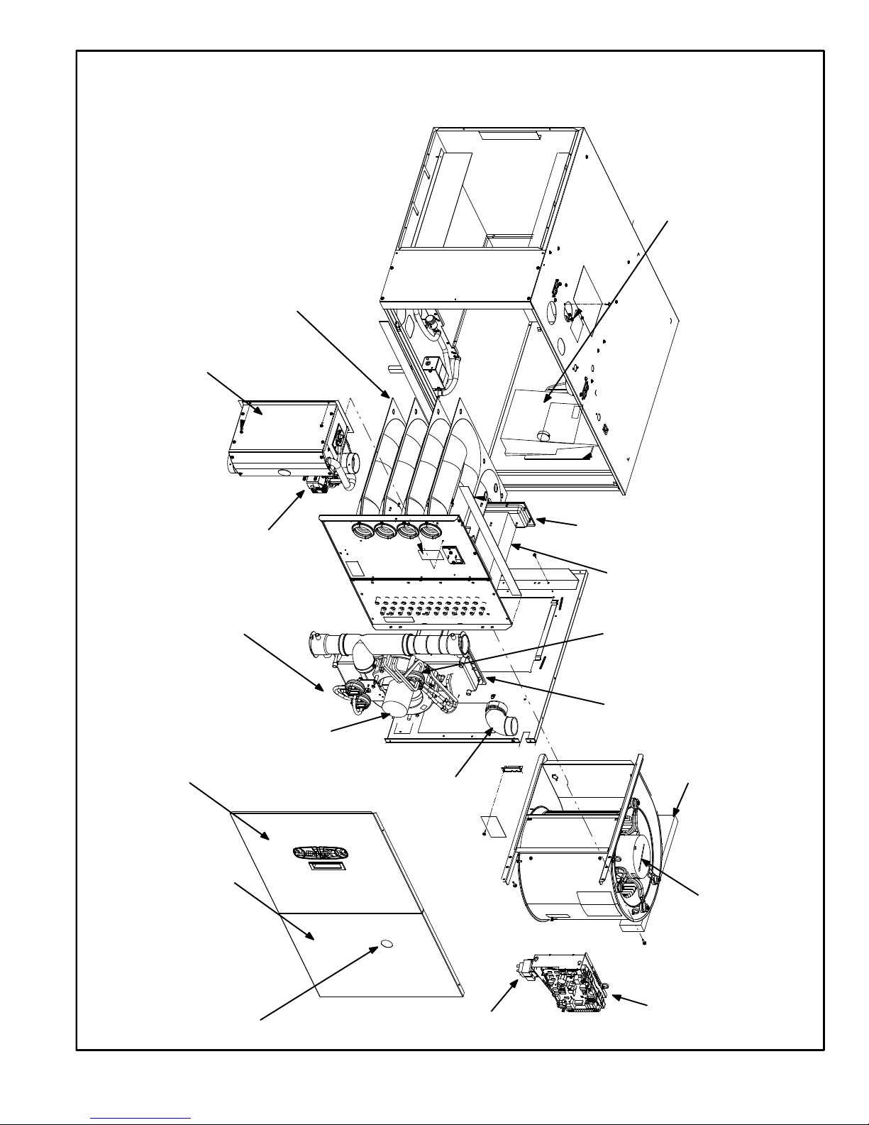
G71MPP PARTS ARRANGEMENT
FIGURE 1
BURNER BOX ASSEMBLY
HEAT EXCHANGER
WARM HEADER
(COLLECTOR BOX)
COLD HEADER
(COLLECTOR BOX)
COMBUSTION AIR
PRESSURE
SWITCHES
CONDENSER COIL
BURNER ACCESS PANEL
BLOWER ACCESS
PANEL
SIGHT GLASS
VARIABLE SPEED
COMBUSTION AIR INDUCER
VARIABLE SPEED
BLOWER MOTOR
INTEGRATED
CONTROL
ELBOW
(shipping location)
TRANSFORMER
BAG ASSEMBLIES
(shipping location)
VARIABLE CAPACITY
GAS VALVE
SHIPPING BLOCK
(−135 units only)
PRESSURE SWITCH
ASSEMBLY WITH
PRESSURE
CONDITIONING
DEVICE
Page 16
Page 16
I−UNIT COMPONENTS
G71MPP unit components are shown in figure 1. The gas
valve, combustion air inducer and burners can be accessed by removing the burner access panel. Electrical
components are in the control box (figure 2) found in the
blower compartment.
G71MPP units are factory equipped with a bottom return air
panel in place. The panel is designed to be field removed as
required for bottom air return. Markings are provided for side
return air and may be cut out in the field.
CAUTION
Electrostatic discharge can affect electronic components. Take precautions during furnace installation and service to protect the furnace’s electronic controls. Precautions will help to avoid control exposure to electrostatic discharge by putting
the furnace, the control and the technician at the
same electrostatic potential. Neutralize electrostatic charge by touching hand and all tools on an
unpainted unit surface, such as the gas valve or
blower deck, before performing any service procedure.
ELECTROSTATIC DISCHARGE (ESD)
Precautions and Procedures
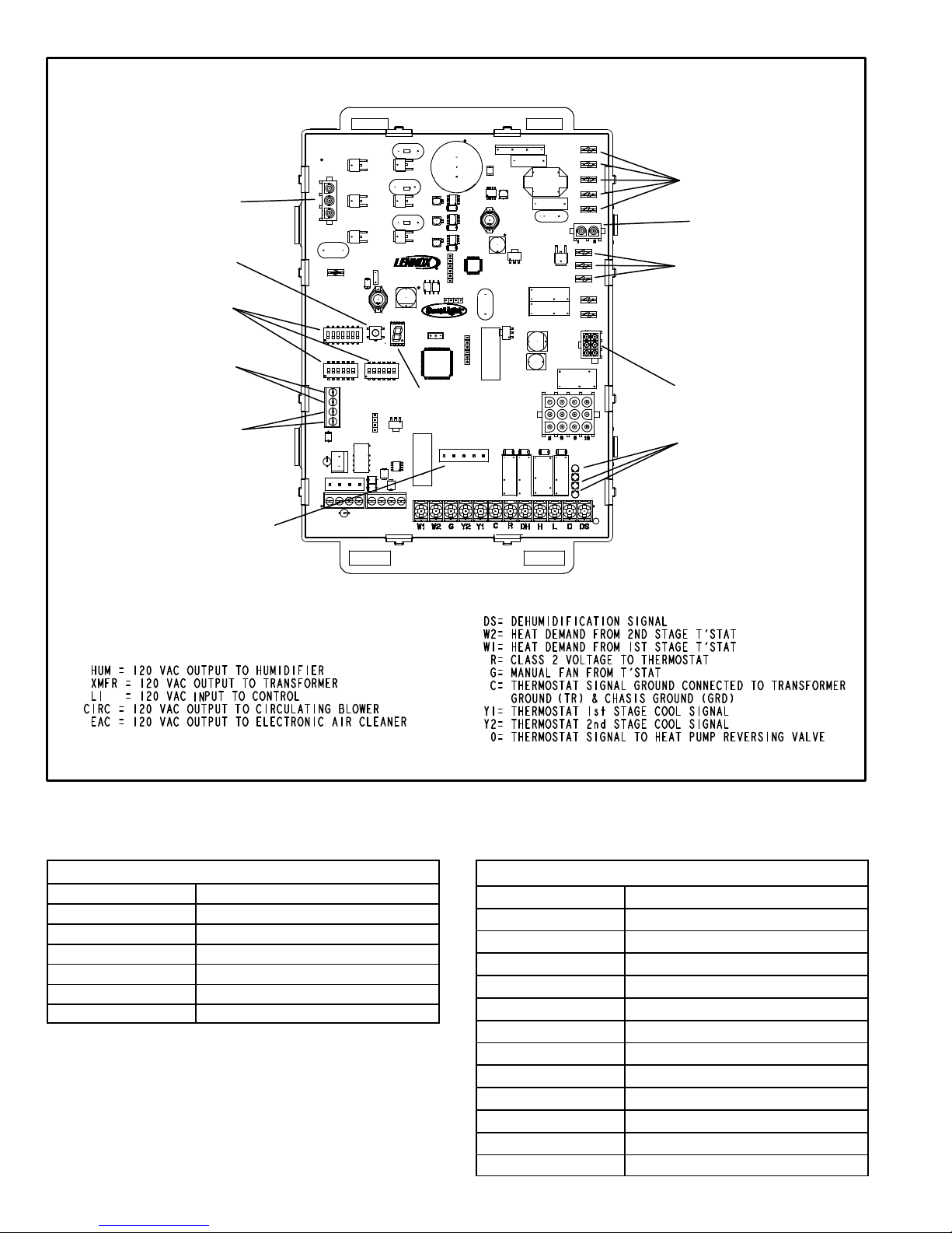
A−Control Box
1. Control Transformer (T1)
A transformer located in the control box provides power to
the low voltage section of the unit. Transformers on all
models are rated 40VA with a 120V primary and a 24V secondary.
2. Door Interlock Switch (S51)
A door interlock switch rated 14A at 125VAC is wired in series with line voltage. When the blower door is removed the
unit will shut down.
FIGURE 2
CONTROL BOX G71MPP
SURELIGHT®
INTEGRATED
CONTROL
TRANSFORMER
CIRCUIT
BREAKER
DOOR INTERLOCK
SWITCH
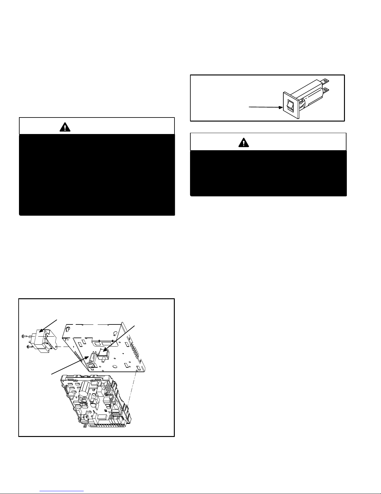
3. Circuit Breaker (CB8)
A 24V circuit breaker is also located in the control box.
The switch provides overcurrent protection to the transformer (T1). The breaker is rated 3A at 32V. If the current
exceeds this limit the breaker will trip and all unit operation will shutdown. The breaker can be manually reset
by pressing the button on the face. See figure 3.
FIGURE 3
CIRCUIT BREAKER CB8
PRESS TO RESET
WARNING
Shock hazard.
Disconnect power before servicing. Integrated
Control Board is not field repairable. If control is inoperable, simply replace entire control.
Can cause injury or death. Unsafe operation will result if repair is attempted.
4. Integrated Control Board(A92)
G71MPP units are equipped with the Lennox SureLight
®
variable capacity integrated control. The system consists
of an ignition / blower control (figures 4 and 5) with control
pin designations in tables 12 and 13 and ignitor (figure 12).
The control provides gas ignition, safety checks and indoor blower control with variable capacity rate gas heating. The furnace combustion air inducer, gas valve and indoor blower are controlled in response to various system
inputs such as thermostat signal, prove and limit switch
signal and flame signal. The control operates with a conventional single or two−stage thermostat. The board features a seven segment LED display, indicating furnace
status (including indoor blower) and error codes. The LED
flashes in single digits. For example using table 25 under
LIMIT CODE, a 2" followed by 5" followed by 0", the limit
switch circuit is open. The board also has two 120 volt accessory terminals (used for a humidifier and electronic air
cleaner) rated at (1) one amp each.
Page 17

Page 17
Electronic Ignition
At the beginning of the heat cycle the SureLight
®
integrated
control monitors the low fire combustion air inducer pressure switch. The control will not begin the heating cycle if
the low fire pressure switch is closed (by−passed). Likewise
the control will not begin the high fire heating cycle if the
high fire pressure switch is closed, and will remain in low
fire heat. However, if the high fire pressure switch closes
during the low fire heat pre−purge, the control will allow high
fire heat. Once the low fire pressure switch is determined to
be open, the combustion air inducer is energized on ignition speed. When the differential in the pressure switch is
great enough, the pressure switch closes and a 15−second
pre−purge begins. If the switch is not proven within 2−1/2
minutes, the inducer is de−energized and the control will initiate vent calibration. If the vent calibration is unsuccessful
the control goes into a 5 minute delay. The control will attempt vent calibration 3 more times before going into a 1
hour soft lockout.
After the 15 second pre−purge period the SureLight ignitor
warms up for 20 seconds after which the gas valve opens
for a 4−second trial for ignition. The ignitor stays energized
during this trial until flame is sensed. If ignition is not proven
during the 4−second trial for ignition, the control will try four
more times with an inter purge and warm−up time between
trials of 35 seconds. After a total of five trials for ignition (including the initial trial), the control goes into Watchguard−
Flame Failure mode. After a 60−minute reset period, the
control will begin the ignition sequence again.
Thermostat Selection Modes
See table 14 for DIP switch settings
The control can be made to operate in three modes: variable capacity, three−stage timed or two−stage. The variable
capacity and two−stage modes are only operational with a
two−stage thermostat. The thermostat selection is made
using dip switches one and / or two (figure 4) and must be
positioned for the particular application.
Variable Capacity
Using a two−stage thermostat the system will operate in a
variable capacity sequence mode. In this mode, the control
will vary the firing rate anywhere between 40% and 100%
of full capacity. The indoor blower will be automatically ad-
justed accordingly to provide the appropriate airflow at any
rate. On the initial call for low fire, the furnace will operate at
40% and will remain there until the heat call is satisfied or a
call for high fire is initiated. If there is a call for high fire the
rate will increase by 10% if the current rate is above 60%.
However if the current rate is below 60% the rate will increase to 70%. After this initial rate increase to 70% capacity, the furnace will increase rate by 10% every 5 minutes
while a high fire heat call is present. If the high fire heat call
is satisfied but the low fire heat call is still present, the furnace will remain at the current firing rate until the demand is
satisfied or another call for high fire is initiated.
Three Stage Timed
Using a single−stage thermostat the system will operate in
a three stage timed mode. Upon a call for heat and a successful ignition, the combustion air inducer will operate at
40% and the indoor blower will adjust to the appropriate
cfm. After a field selectable 7 or 12 minute delay period, the
inducer RPM will increase and the unit will operate at 70%.
The indoor blower will adjust to the appropriate cfm. After a
factory set non−adjustable 10 minute delay expires the furnace will increase rate to 100%. The indoor blower will adjust to the appropriate cfm.
Two−Stage
The system will also operate in conventional two−stage
mode.
While in two−stage mode, the furnace will fire on low
fire (70% rate). The combustion air inducer will operate at
70% and the indoor blower will adjust to the appropriate
cfm. The unit will switch to high fire on a W2 call from the
thermostat. After a 30 second recognition period (during
which the integrated control will recieve a continuous W2
call) expires the furnace will increase to 100% rate. The inducer will increase to 100% speed and the indoor blower
will adjust to appropriate cfm. If there is a simultaneous call
for first and second stage heat, the unit will fire on first stage
heat and switch to second stage heat after 30 seconds of
operation.
Page 18
Page 18
INTEGRATED CONTROL
THERMOSTAT CONNECTIONS (TB1)
1/4" QUICK CONNECT TERMINALS
H= 24V HUMIDIFIER OUTPUT
L= LENNOX SYSTEM OPERATION MONITOR
NEUTRALS= 120 VAC NEUTRAL
FIGURE 4
+
FLAME
SENSE
COMBUSTION
AIR INDUCER
CONNECTOR
DIP SWITCHES
OUTDOOR AIR
SENSOR
TERMINALS
(Future Use)
DISCHARGE AIR
SENSOR
TERMINALS
(Future Use)
W915
W951
W914
ON−BOARD
LINKS
INDOOR
BLOWER
CONNECTOR
EAC
HUM
LINE VOLTAGE
TERMINALS
NEUTRAL
TERMINALS
IGNITOR
CONNECTOR
7−SEGMENT
DIAGNOSTIC LED
DIAGNOSTIC
PUSH BUTTON
FACTORY TEST
HEADER PINS.
FACTORY USE ONLY.
TABLE 12
SureLight Board
®
6 Pin Terminal Designation
PIN # Function
1 Data Input From Motor
2 Common
3 Furnace Size Resistor Input
4 Data Output To Motor
5 5 Volt Bias Supply
6 Furnace Size Resistor Input
TABLE 13
SureLight Board 12Pin Terminal Designation
PIN # Function
1 Not used
2 High Fire Pressure Switch
3 Rollout In
4 Ground
5 24V Hot
6 Primary Limit In
7 Gas Valve
8 Gas Valve Common
9 24V Neutral
10 Ground
11 Primary Limit Switch Out
12 Low Fire Pressure Switch
Page 19
Page 19
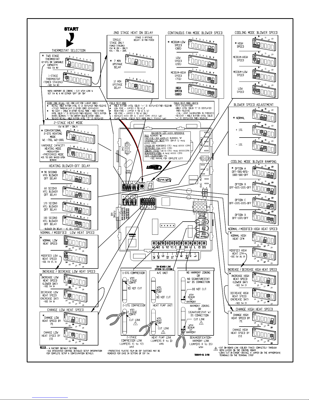
FIGURE 5
G71MPP INTEGRATED CONTROL CONFIGURATION GUIDE
Page 20

Page 20
TABLE 14
Thermostat Selection Switch Settings
Operation
Thermostat Switch 1 Switch 2 Switch 3
Variable Capacity Heat
(40% to 100%)
Two−Stage Off On Off
Three−Stage Heat
(40%, 70%, 100%)
Single−Stage On Off 2nd stage delay
OFF = 7 minutes
ON = 12 minutes
3rd stage delay
10 minutes fixed
Two−Stage Heat (W1 70%, W2 100%) Two−Stage Off Off Off
Heating Operation DIP Switch Settings −− Figure 4
Switch 1 −− Thermostat Selection −− This unit may be used
with either a single−stage or two−stage thermostat. The
thermostat selection is made using a DIP switch which
must be properly positioned for the particular application.
The DIP switch is factory−positioned for use with a two−
stage thermostat. If a single−stage thermostat is to be used,
the DIP switch must be repositioned. See table 14.
Switch 2 −− Operating Mode with Two−Stage Thermostat −− If a two−stage thermostat is used, the furnace can
operate in either variable−capacity or conventional two−
stage mode. When variable−capacity mode is selected, the
firing rate of the unit is varied to maximize comfort. Conventional two−stage mode is the factory default setting. See
table 14.
Switch 3 −− Second−Stage Heat On Delay −− If a single−
stage thermostat is used, the integrated control can be
used to energize second−stage heat after either 7 minutes
or 12 minutes of first−stage heat operation. See table 14.
Switches 4 and 5 −− Blower−Off Delay −− The blower−on
delay of 45 seconds is not adjustable. The blower−off delay
(time that the blower operates after the heating demand
has been satisfied) can be adjusted by moving switches 4
and 5 on the integrated control. The unit is shipped from the
factory with a blower−off delay of 90 seconds. The blower
off delay affects comfort and is adjustable to satisfy individual applications. Adjust the blower off delay to achieve a
supply air temperature between 90° and 110°F at the exact
moment that the blower is de−energized. Longer off delay
settings provide lower supply air temperatures; shorter settings provide higher supply air temperatures. Table 15 provides the blower off timings that will result from different
switch settings.
TABLE 15
Blower Off Delay Switch Settings
Blower Off Delay
(Seconds)
Switch 4 Switch 5
60 Off On
90 Off Off
120 On Off
180 On On
Indoor Blower Operation DIP Switch Settings
Switches 6 and 7 −− Continuous Indoor Fan Operation −−
Blower Speed − Switches 6 and 7 are used to select blower
motor speeds during continuous indoor blower operation.
The unit is shipped from the factory with DIP switches positioned for medium low (2) speed during continuous indoor
blower operation. The table below provides the continuous
blower speeds that will result from various switch settings.
Refer to tables 1 through 11 for corresponding cfm values.
TABLE 16
Continuous Indoor Fan
Speed
Switch 6 Switch 7
1 − Low (28%) Off On
2 − Medium Low
(38%)
(Factory)
Off Off
3 − Medium High
(70%)
On Off
4 − High (100%) On On
Switches 8 and 9 −− Cooling Mode Blower Speed −−
Switches 8 and 9 are used to select cooling blower motor
speed. The unit is shipped from the factory with the DIP
switches positioned for high speed (4) indoor blower motor
operation during the cooling mode. The table below provides the cooling mode blower speeds that will result from
different switch settings. Refer to tables 1 through 11 for
corresponding cfm values.
TABLE 17
Cooling Mode Blower Speeds
Speed
Switch 8 Switch 9
1 − Low On On
2 − Medium Low Off On
3 − Medium High On Off
4 − High (Factory) Off Off
Page 21
Page 21
Switches 10 and 11 −− Cooling Mode Blower Speed Adjustment −− Switches 10 and 11 are used to select blower
speed adjustment settings. The unit is shipped from the
factory with the DIP switches positioned for NORMAL (no)
adjustment. The DIP switches may be positioned to adjust
the blower speed by +10% or −10% to better suit the application. The table below provides blower speed adjustments that will result from different switch settings. Refer to
tables 1 through 11 for corresponding cfm values. With
switches 10 and 11 set to ON, motor will bypass ramping
profiles and all delays and immediately upon a call for cool,
run at COOLING speed selected. LED will continue to operate as normal. This mode is used to check motor operation.
TABLE 18
Blower Speed Adjustment
Adjustment
Switch 10 Switch 11
+10% (approx.) On Off
NORMAL (Factory) Off Off
−10% (approx.) Off On
MOTOR TEST On On
Switches 12 and 13 −− Cooling Mode Blower Speed
Ramping −− Switches 12 and 13 are used to select cooling
mode blower speed ramping options. Blower speed ramping may be used to enhance dehumidification performance. The switches are factory set at option A which has
the greatest effect on blower motor performance. Table 19
provides the cooling mode blower speed ramping options
that will result from different switch settings. The cooling
mode blower speed ramping options are detailed below.
TABLE 19
Cooling Mode Blower Speed Ramping
Ramping Option
Switch 12 Switch 13
A (Factory) Off Off
B On Off
C Off On
D On On
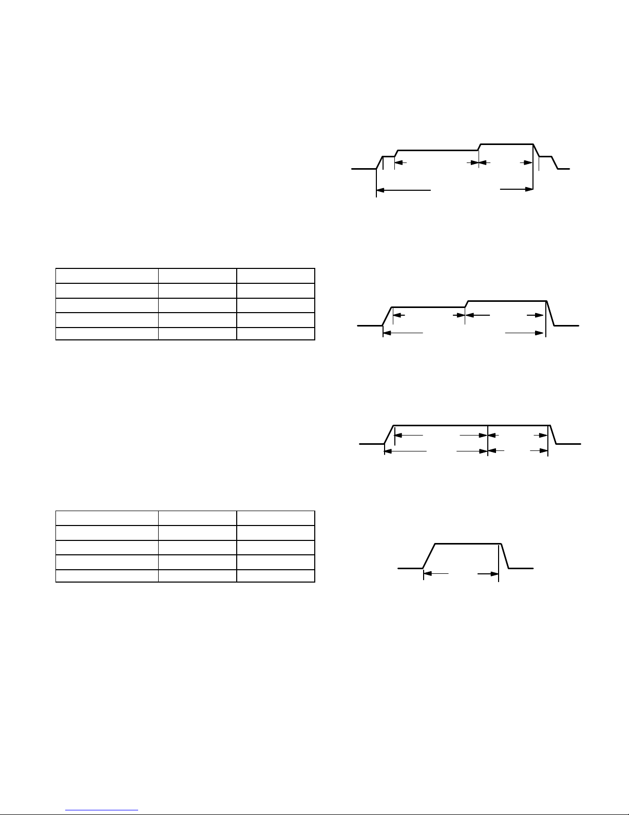
Ramping Option A (Factory Selection)
D Motor runs at 50% for 30 seconds.
D Motor then runs at 82% for approximately 7−1/2 min-
utes.
D If demand has not been satisfied after 7−1/2 minutes,
motor runs at 100% until demand is satisfied.
D Once demand is met, motor runs at 50% for 30 sec-
onds then ramps down to stop.
OFF
OFF
1/2 MIN
50% CFM
COOLING DEMAND
7 1/2 MIN
82% CFM
100%
CFM
1/2 MIN
50% CFM
Ramping Option B
S Motor runs at 82% for approximately 7−1/2 minutes. If
demand has not been satisfied after 7−1/2 minutes,
motor runs at 100% until demand is satisfied.
S Once demand is met, motor ramps down to stop.
OFF
OFF
82%CFM
100% CFM
COOLING DEMAND
7 1/2 MIN
Ramping Option C
S Motor runs at 100% until demand is satisfied.
S Once demand is met, motor runs at 100% for 45 sec-
onds then ramps down to stop.
OFF
OFF
100% CFM
100% CFM
DEMAND
45 SEC.
Ramping Option D
S Motor runs at 100% until demand is satisfied.
S Once demand is met, motor ramps down to stop.
OFFOFF
100% CFM
COOLING
DEMAND
Page 22
Page 22
TABLE 20
Low Heat Blower Speeds
Thermostat
Demand
Blower
Speed
Adjust-
ments
DIP SWITCH SETTINGS
14 15 16
Low Heat
(R to W1)
+15% On Off On
+7.5% On Off Off
Normal Off Off Off
−7.5% On On Off
−15% On On On
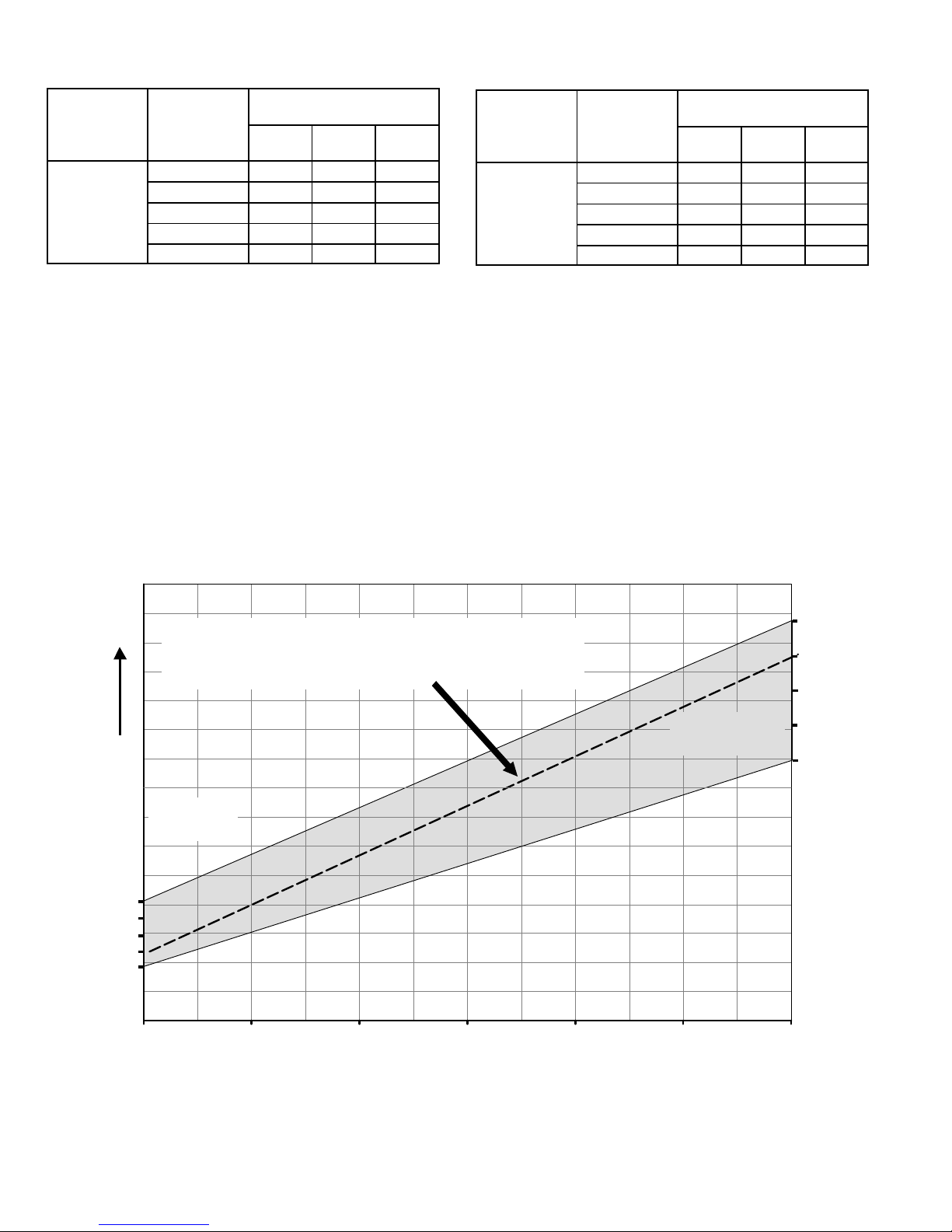
Switches 14 through19 −− Heating Mode Blower Speed
−− Switches 14 through 19 are used to select heating mode
blower motor speeds. These switches are factory set at the
OFF position which provides 100 % of normal speed during
HIGH HEAT demand, 70% of normal speed during MID−
RANGE HEAT demand and 40% of normal speed during
LOW HEAT demand. Switches 14, 15 and 16 are used to
adjust the LOW FIRE blower motor speed. Switches 17, 18
and 19 are used to adjust the HIGH FIRE blower motor
speed. Figure 6 and tables 20 and 21 provides the heating
mode blower speeds that will result from different switch
settings. Figure 6 indicates the effect the DIP switch settings (tables 20 &21 above) have upon the heating airflow
at various furnace firing rates.
Refer to tables 1 through 11 for corresponding cfm values.
TABLE 21
High Heat Blower Speeds
Thermostat
Demand
Blower
Speed
Adjust-
ments
DIP SWITCH SETTINGS
17 18 19
High Heat
(R to
W1 & W2)
+15% On Off On
+7.5% On Off Off
Normal
Off Off Off
−7.5% On On Off
−15% On On On
Low Fire
Dip Switches
14, 15, 16
High Fire
Dip Switches
17, 18, 19
Airflow Determination
S Identify blower speed adjustment points at low and high fire
S Airflow will lie on straight line between these two points and will fall within
the shaded area as shown
EXAMPLE −7.5% at low fire +7.5% at high fire
40%
50%
60%
70%
80%
90%
100%
RATE (%)
+15%
+7.5%
−7.5%
−15%
Nominal
−15%
Nominal
−7.5%
+7.5%
+15%
Increasing
Airflow
FIGURE 6
Page 23

Page 23
On−Board Link W914 −− Figure 4
On−board link W914, is a clippable connection between terminals DS and R on the integrated control. W914 must be
cut when the furnace is installed with either the Harmony
IIIt zone control or a thermostat which features humidity
control. If the link is left intact the PWM signal from the Harmony III control will be blocked and also lead to control
damage. Refer to table 26 for operation sequence in applications including G71MPP, a thermostat which features
humidity control and a single−speed outdoor unit. Table 27
gives the operation sequence in applications with a two−
speed outdoor unit.
On−Board Link W951 −− Figure 4
On−board link W951 is a clippable connection between terminals R and O on the integrated control. W951 must be cut
when the furnace is installed in applications which include a
heat pump unit and a thermostat which features dual fuel
use. If the link is left intact, terminal O" will remain energized eliminating the HEAT MODE in the heat pump.
On−Board Link W915 −− Figure 4
On−board link W915 is a clippable connection between terminals Y1 and Y2 on the integrated control. W915 must be
cut if two−stage cooling will be used. If the link is not cut the
outdoor unit will operate in second−stage cooling only.
Diagnostic LED −− Figure 4
The seven−segment diagnostic LED displays operating
status, target airflow, error codes and other information.
The table on page 58 lists diagnostic LED codes.
Diagnostic Push Button −− Figure 4
The diagnostic push button is located adjacent to the
seven−segment diagnostic LED. This button is used to enable the Error Code Recall mode and the Field Test mode.
Press the button and hold it to cycle through a menu of options. Every five seconds a new menu item will be displayed. When the button is released, the displayed item will
be selected. Once all items in the menu have been displayed, the menu resumes from the beginning until the button is released.
Error Code Recall Mode
Select "E" from the menu to access the most recent 10 error
codes. Select c" from the Error Code Recall menu to clear
all error codes. Button must be pressed a second time
while c" is flashing to confirm command to delete codes.
Press the button until a solid ≡" is displayed to exit the Error
Code Recall mode.
Field Test Mode
Use the diagnostic push button to scroll through the menu
as described above. Release the button when the LED
flashes −" to select the Field Test mode.
While in the Field Test mode the technician can:
D Initiate furnace ignition and move to and hold low−fire
rate by applying a R to W1 jumper.
D Initiate furnace ignition sequence and move to and
hold high−fire rate by applying a jumper from R to W1
and W2.
D Initiate furnace ignition sequence and move to and
hold mid−fire rate by applying a jumper to R and W2.
D Apply then remove the jumper from R to W1 and W2 to
change the firing rate from low fire to mid fire and high
fire.
D
A vent calibration sequence can be initiated even if a
thermostat signal is not present. Press and hold the
push button until a solid C" is displayed. Release the
button and calibration will begin. The furnace will perform the high−fire and low−fire pressure switch calibrations and display CAL". After calibration, the LED will
return to the flashing −" display.
During Field Test mode operation, all safety switches are
still in the circuit (they are not by−passed) and indoor blower
performance and timings will match DIP switch selections.
Current furnace firing rate, indoor blower CFM and flame
signal will be displayed. To exit the Field Test mode, press
and hold the button. The menu will resume from the beginning. Also, cycle the main power to exit the Field Test mode.
The integrated control will automatically exit the Field Test
mode after 45 minutes of operation.
Page 24

Page 24
TABLE 22
Idle Menu Options
These options are displayed on the menu when the button is pressed during normal operation
DISPLAY
ACTION (when button released)
No change (idle) remain in idle mode
Solid E" enter diagnostic mode
Solid −" enter field test mode
NOTE − No change implies the display will continue to show whatever is currently being displayed for normal operation
TABLE 23
Field Test Menu Options
These options are displayed when the button is used in Field Test Mode
DISPLAY
ACTION (when button released)
No change (blinking −") remain in field test mode
Solid −" exit field test mode
Solid c" start pressure switch calibration
TABLE 24
Field Test Menu Options
These options are displayed when the button is used in diagnostic recall mode
DISPLAY ACTION (when button released)
No change (displaying error history) remain in diagnostic recall mode
Solid (3 horizontal bars) exit diagnostic recall mode
Solid c" clear error history
Once the button is released to clear the error history a blinking c" will be shown on the display for up to 10 seconds. During
this time the user must press and release the button one additional time to confirm the action of deleting the error history.
Once the error history is deleted it cannot be recovered.
Page 25
Page 25
TABLE 25
LED 7 Segment Status / Error Code
Press the diagnostic push button and hold it to cycle through a menu of options. Every five seconds a new menu item will be
displayed. Release the button when the desired mode is displayed.
When the solid E" is displayed, the control enters the Error Code Recall mode. Error Code Recall mode menu options: No change (displaying error history) remains in Error Code Recall mode; solid ≡" exits Error Code Recall mode; and solid c" clears the error history. Must
press button while flashing c" is displayed to clear error codes.
When the solid −" is displayed, the control enters the Field Test mode. Field Test mode menu options: Solid C" starts pressure switch
calibration; blinking −" exits Field Test mode.
Flash Code Diagnostic Code / Status of Furnace
S Idle mode (Decimal blinks at 1 Hz 1/2 sec. On and 1/2 sec. Off
A CFM Display (1 sec. On 1/2 sec Off, CFM value)
C Staged Cooling (1 sec. On 1/2 sec. Off or 2 Stage 1 sec. pause CFM pause, Repeat codes)
d Dehumidification Mode (1 sec. On 1 sec Off, CFM, Pause Repeat Codes)
h Variable Capacity Heat (1 sec On 1/2 sec Off % of input rate Pause CFM Pause Repeat Codes)
H Staged Heat (1 sec On 1/2 sec Off or 2 Stage 1 sec, CFM Pause Repeat Codes)
110 Low Line Voltage
113 High Line Voltage
115 Low 24V (control will restart if the error recovers)
125 Control failed self check, internal error, failed hardware. Control will restart if error recovers
180 Outdoor Air Sensor Failure − no error if just disconnected, only show if shorted or out of range
200 Rollout circuit open or previously opened
201 Circulator / COM failure − unable to communicate w / circulating motor (blower)
202 Circulating motor / resistor mis−match or resistor missing
204 Gas Valve Miswired − Resume normal operation after error corrected
223 Low Pressure Switch Failed Open
224 Low Pressure Switch Failed Closed
225 High Pressure Switch Failed Open
226 High Pressure Switch Failed Closed
227 Low Pressure Switch Opened during TFI or Run mode
228 Unable to perform successful pressure switch calibration mode
240 Low Flame Mode − Run Mode
241 Flame sense out of sequence − flame still present
250 Limit switch circuit open
270 Watchguard − Exceed maximum number of retries. No flame current sensed
271
Watchguard − Exceed maximum number ignition retries where the last retry was due to pressure switch
opening
272
Watchguard − Exceed maximum number of recycles where the last recycle was due to pressure switch
opening
273 Watchguard − Exceed maximum number of recycles where the last retry was due to flame failure
274 Watchguard − The limit remained open longer than 3 minutes
275 Watchguard − Flame sensed out of sequence; flame signal gone
290 Ignitor circuit Fault − failed ignitor or triggering circuitry
291 Restricted airflow − available CFM below min. firing rate
292 Circulator motor unable to start (seized bearings, stuck wheel, etc)
294 Inducer motor amp draw too high
310 Discharge air sensor failure − no error if just disconnected, only show if shorted or out of range
311 Restricted airflow heating mode − target input rate reduced to match available circulator CFM
312 Restricted airflow cooling or continuous fan mode − information only
Page 26

Page 26
TABLE 26
OPERATING SEQUENCE
G71MPP, ComfortSenset 7000 Thermostat and Single−Stage Outdoor Unit
OPERATING
SEQUENCE
SYSTEM DEMAND SYSTEM RESPONSE
System
Condition
Step
Thermostat Demand Relative Humidity
Compressor
Blower
CFM
(COOL)
Comments
Y1 O G
W1
Status D
NO CALL FOR DEHUMIDIFICATION
Normal Operation 1 On On On Acceptable
24
VAC
High 100%
Compressor and indoor
blower follow thermostat
demand
BASIC MODE (only active on a Y1 thermostat demand)
Normal Operation 1 On On On Acceptable
24
VAC
High 100%
ComfortSenset 7000
thermostat energizes Y1
and de−energizes D on a
call for de−humidification
Dehumidification
Call
2 On On On Demand
0
VAC
High 70%
PRECISION MODE (operates independent of a Y1 thermostat demand)
Normal Operation 1 On On On Acceptable
24
VAC
High 100%
Dehumidification mode
begins when humidity is
greater than set point
Dehumidification
call
2 On On On Demand
0
VAC
High 70%
Dehumidification
call ONLY
1 On On On Demand
0
VAC
High 70%
ComfortSenset 7000
thermostat will keep outdoor unit energized after
cooling temperature setpoint has been reached in
order to maintain room
humidity setpoint.
On−board links at indoor unit with a single−stage outdoor unit:
With Condensing unit − Cut W914 (R to DS) on SureLight
®
integrated control;
With Heat Pump − Cut W914 (R to DS) & W951 (R to O) on SureLight
®
integrated
control.
Page 27

Page 27
TABLE 27
OPERATING SEQUENCE
G71MPP, ComfortSenset 7000 Thermostat and Two−Stage Outdoor Unit
OPERATING
SEQUENCE
SYSTEM DEMAND SYSTEM RESPONSE
System
Condition
Step
Thermostat Demand Relative Humidity
Compressor
Blower
CFM
(COOL)
Comments
Y1
Y2
O
G
W1W
2
Status D
NO CALL FOR DEHUMIDIFICATION
Normal Operation −
Y1
1 On On
On
Acceptable
24
VAC
Low 70%
Compressor and indoor
blower follow thermostat
demand
Normal Operation −
Y2
2 On
On
On
On
Acceptable
24
VAC
High 100%
ROOM THERMOSTAT CALLS FOR FIRST STAGE COOLING
BASIC MODE (only active on a Y1 thermostat demand)
Normal Operation 1 On On
On
Acceptable
24
VAC
Low 70%
ComfortSenset 7000
thermostat energizes Y2
and de−energizes D on a
call for de−humidification
Dehumidification
Call
2 On
On
On
On
Demand
0
VAC
High 70%
PRECISION MODE (operates independent of a Y1 thermostat demand)
Normal Operation 1 On On
On
Acceptable
24
VAC
Low 70%
Dehumidification mode
begins when humidity is
greater than set point
Dehumidification
call
2 On
On
On
On
Demand
0
VAC
High 70%
Dehumidification
call ONLY
1 On
On
On
On
Demand
0
VAC
High 70%
ComfortSenset 7000
thermostat will keep outdoor unit energized after
cooling temperature setpoint has been reached
in order to maintain room
humidity setpoint.*
ROOM THERMOSTAT CALLS FOR FIRST AND SECOND STAGE COOLING
BASIC MODE (only active on a Y1 thermostat demand)
Normal Operation 1 On
On
On
On
Acceptable
24
VAC
High 100%
ComfortSenset 7000
thermostat energizes Y2
and de−energizes D on a
call for de−humidification
Dehumidification
Call
2 On
On
On
On
Demand
0
VAC
High 70%
PRECISION MODE (operates independent of a Y1 thermostat demand)
Normal Operation 1 On On
On
Acceptable
24
VAC
Low 70%
Dehumidification mode
begins when humidity is
greater than set point
Dehumidification
call
2 On
On
On
On
Demand
0
VAC
High 70%
Dehumidification
call ONLY
1 On
On
On
On
Demand
0
VAC
High 70%
ComfortSenset 7000
thermostat will keep outdoor unit energized after
cooling temperature setpoint has been reached
in order to maintain room
humidity setpoint.
On−board links at indoor unit with a two−stage outdoor unit:
Cut factory link from Y1 to Y2 or cut W915 (Y1 to Y2) on SureLight
®
integrated
control.
With Condensing unit − Cut W914 (R to DS) on SureLight
®
integrated control;
With Heat Pump − Cut W914 (R to DS) & W951 (R to O) on SureLight
®
integrated control.
Page 28
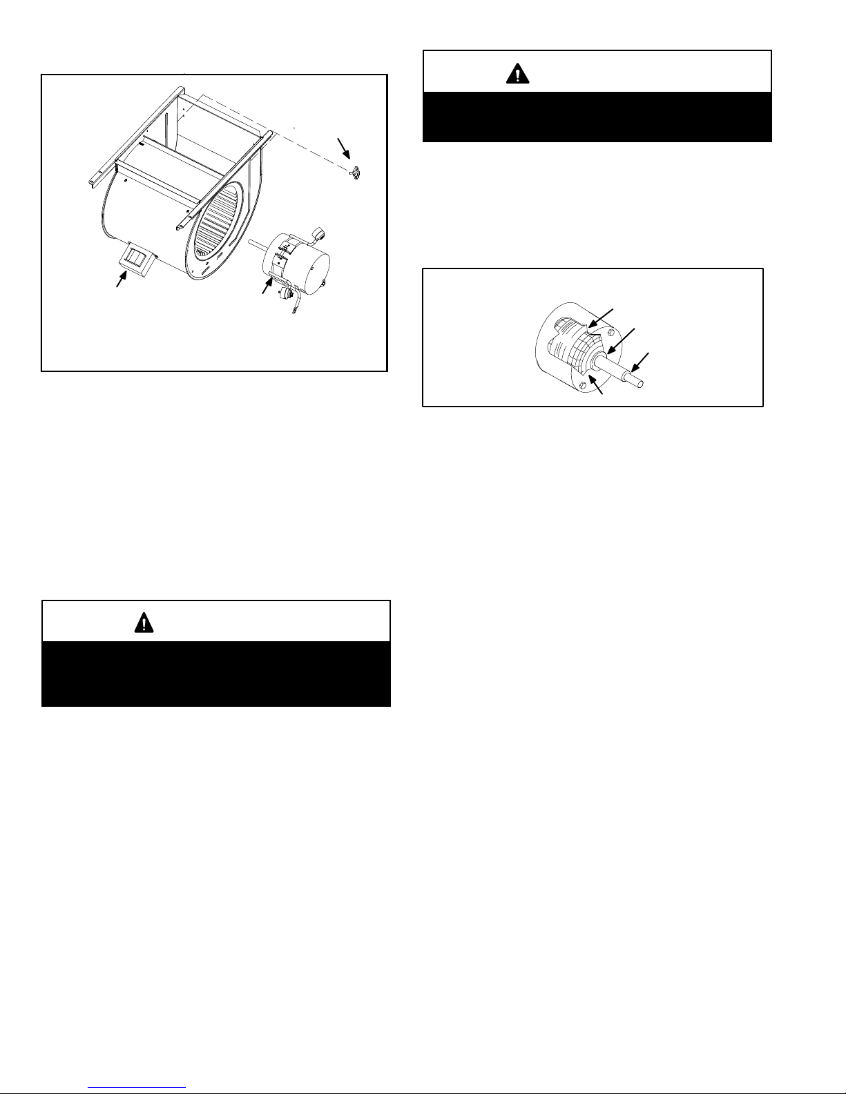
Page 28
B−Blower Compartment Figure 7
FIGURE 7
SECONDARY
LIMITS (2)
Power Choke
(5 Ton Only)
Blower Motor
(B3)
To Remove Blower From Unit: Remove Integrated Control,
Door Interlock Switch, Bolts and Wiring Jackplugs.
Then Slide Out Front of Unit.
1. Secondary Limit (S21)
The secondary limits (S21) on G71MPP units are located in
the blower compartment on the back side of the blower housing. See figure 7. All G71MPP units are equipped with two secondary limits. When excess heat is sensed in the blower
compartment, the limit will open. If the limit is open, the furnace
control energizes the supply air blower and closes the gas
valve. The limit automatically resets when unit temperature returns to normal. The switch is factory set to open at 125°F
and cannot be adjusted.
2. Blower Motor (B3)
WARNING
During blower operation, the ECM motor emits energy that may interfere with pacemaker operation. Interference is reduced by both the sheet metal cabinet
and distance.
The G71MPP line uses two different motor sizes, a 1/2 HP
and 1 HP. The motor communicates with the integrated control via a 2−way serial connection. The motor receives all necessary functional parameters from the integrated control and
does not rely on a factory program like traditional variable
speed motors. The wiring harness connecting the motor to
the integrated control includes a resistor which sets the motor
parameters the integrated control will use. See wiring diagram regarding wiring harness. G71MPP units use a threephase, electronically controlled D.C. brushless motor (controller converts single phase a.c. to three phase D.C.), with a
permanent-magnet-type rotor (figure 8). Because this motor
has a permanent magnet rotor it does not need brushes like
conventional D.C. motors.
Internal components are shown in figure 8. The stator windings are split into three poles which are electrically connected
to the controller. This arrangement all o w s moto r windin g s to
turn on and off in sequence by the controller.
IMPORTANT
Earlier ECM motors used on other Lennox furnace
models are not interchangeable with motors used on
the G71MPP furnace line.
A solid-state controller is permanently attached to the
motor. The controller is primarily an A.C. to D.C. converter. Converted D.C. power is used to drive the motor.
The controller contains a microprocessor which monitors varying conditions inside the motor (such as motor
workload).
G71MPP BLOWER MOTOR COMPONENTS
FIGURE 8
STATOR
(WINDINGS)
OUTPUT
SHAFT
BEARING
ROTOR
The controller uses sensing devices to sense what position
the rotor is in at any given time. By sensing the position of the
rotor and then switching the motor windings on and off in sequence, the rotor shaft turns the blower.
All G71MPP blower motors use single phase power. An
external run capacitor is not used. The motor uses permanently lubricated ball-type bearings..
Internal Operation
The motor is controlled via serial communication between
the ignition control on the furnace and the controller attached to the motor shell. The messages sent back and
forth between the two controls serve to communicate rotational direction, demand, motor size, current draw, torque,
and rpm, among other variables.
Motor rpm is continually adjusted internally to maintain
constant static pressure against the blower wheel. The controller monitors the static work load on the motor and motor ampdraw to determine the amount of rpm adjustment. Blower rpm
may be adjusted any amount in order to maintain a constant
cfm as shown in Blower Ratings Tables. The cfm remains relatively stable over a broad range of static pressure. Since the
blower constantly adjusts rpm to maintain a specified cfm, motor rpm is not rated. Hence, the terms cool speed" , heat
speed " or speed tap" in this manual, on the unit wiring diagram and on blower B3, refer to blower cfm regardless of motor rpm.
Initial Power Up
When line voltage is applied to B3, there will be a large inrush
of power lasting less than 1/4 second. This inrush charges a
bank of DC filter capacitors inside the controller. If the disconnect switch is bounced when the disconnect is closed, the disconnect contacts may become welded. Try not to bounce the
disconnect switch when applying power to the unit.
Page 29

Page 29
Motor Start-Up
When B3 begins start-up, the motor gently vibrates back and
forth for a moment. This is normal. During this time the electronic controller is determining the exact position of the rotor.
Once the motor begins turning, the controller slowly eases
the motor up to speed (this is called soft-start"). The motor
may take as long as 10-15 seconds to reach full speed. If the
motor does not reach 200rpm within 13 seconds, the motor
shuts down. Then the motor will immediately attempt a restart. The shutdown feature provides protection in case of a
frozen bearing or blocked blower wheel. The motor may attempt to start eight times. If the motor does not start after the
eighth try, the controller locks out. Reset controller by momentarily turning off power to unit.
The DC filter capacitors inside the controller are connected
electrically to the motor supply wires. The capacitors take
approximately 5 minutes to discharge when the disconnect
is opened. For this reason it is necessary to wait at least 5
minutes after turning off power to the unit before attempting to service motor.
DANGER
Disconnect power from unit and
wait at least five minutes to allow
capacitors to discharge before attempting to service motor. Failure
to wait may cause personal injury
or death.
Power Choke (L13)
A choke coil is used on G71MPP 5 ton 1 hp units. The
ch oke is located on the blower housing and is used to supress
transient current spikes.
FIGURE 9
BLOWER B3 HARNESS CONNECTORS
MOTOR with IINTEGRATED
CONTROLLER
SHAFT
P49 4 Pin
P48 5 Pin
J48 5 Pin Line Voltage Connector
J49 4 Pin Control Connector
J48 5 Pin
J49 4 Pin
Page 30

Page 30
Troubleshooting
To verify motor operation see steps below:
1− Remove J48 (5 pin power plug) from P48 on the motor.
2− With the power on at the furnace and door switch depressed, use a test meter to verify 120V between pins
4 and 5 on J48.
3− Reconnect J48 to P48 on the motor.
4− Remove J49 (4 pin low voltage connector) from P49
on the motor.
5− Using test jumpers, apply 24V to pins 3 and 4 on P49
on the motor.
Note: Do not apply 24V to pins 2 and 4 on P49. Doing so
will cause permanent damage to the motor.
6− Motor should run at 75%.
7− Test is complete. Remove jumpers and reconnect
plugs.
Another option is to use the TECMate PRO with the 16 to
4 pin adaptor. The use of the TECMate PRO isolates the
motor from the integrated control. Follow the instructions
provided with the kit. If the motor runs do not replace.
FIGURE 10
BLOWER B3 HARNESS CONNECTORS
MOTOR with IINTEGRATED
CONTROLLER
SHAFT
P49 4 Pin
P48 5 Pin
P48 5 Pin
P49 4 Pin
J48 Connector
installed on motor
P49 4 Pin
120v
0
240v
5
4
3
2
1
J48 Connector
24v Transformer
J49 Connector
Page 31

Page 31
Harmony IIIt
When the G71MPP is installed in Harmony III applications,
the Harmony III signal is connected to the DS terminals on
the integrated control (figure 4). In this application dip
switch one and dip switch two (which configures to various
thermostats), is overridden. The discharge air temperature
(if used) is also ignored. In order for proper operation on
board jumper W914 must be clipped.
The PWM signal (70−90 Hz with a 3−97% duty cycle) controls the indoor blower motor linearly between the minimum
(shown in table 28) and the maximum CFM set by COOL-
ING dip switches eight through 13. (3% duty cycle = MIN,
97% duty cycle = MAX).
TABLE 28
Minimum CFM
Cool Speed
1/2HP 1HP
High 250 450
Medium−High 250 450
Medium−Low 250 450
Low 250 450
If there is a W1 heat call while the indoor blower is controlled by Harmony III PWM signal, the integrated control
will after a successful ignition sequence and stabilization
period, modulate the correct firing rate.
Note − All on / off heating and cooling indoor blower
delays are still present with Harmony III.
PWM signal is present at all times with a default value of 3%
duty cycle. Upon the need for a higher duty cycle (more
CFM), the duty cycle will step up at a rate of 1% per second.
Upon a need for less duty cycle, (less or no CFM) the duty
cycle will immediately step down to the demanded % or default 3% (off).
Along with the PWM signal is a 24VAC Enable signal that is
connected on the integrated control terminal G". The integrated control will not obey the PWM signal unless the enable signal is present.
C−Heating Components
1. Ignitor
The ignitor is made of durable silicon nitride. Ignitor longevity is enhanced by controlling voltage to the ignitor. The
SureLight
®
control provides a regulated 95 volts to the ignitor for consistent ignition and long ignitor life. Ohm value
should be 25 to 47. See figure 12 for ignitor location.
2. Flame Sensor
A flame sensor is located on the left side of the burner support. See figure 11. The sensor is mounted on the flame rollout plate and the tip protrudes into the flame envelope of
the left−most burner. The sensor can be removed for service without removing any part of the burners. During operation, flame is sensed by current passed through the
flame and sensing electrode. The SureLight control allows
the gas valve to remain open as long as flame signal is
sensed. To check flame sense signal use the push−button
found on the integrated control and go to Field Test Mode.
The menu will display the flame signal. Table 29 shows the
flame signal for the G71MPP unit.
TABLE 29
Flame Signal in Microamps
Normal
Low Drop Out
2.6 or greater 2.5 or less 1.1
NOTE − A much higher than normal micro amp reading
(15 for example) may appear when checking flame signal.
FIGURE 11
5/16"
Sensor
Page 32

Page 32
FIGURE 12
21/64"
7/32’
5/8
"
Ignitor Location
BURNERS TOP VIEW
BURNERS FRONT VIEW
MEASUREMENT IS TO
I.D. OF RETENTION
RING
IGNITOR
BRACKET
3. Duralock Heat Exchanger
G71MPP units use an aluminized steel primary and
stainless steel secondary heat exchanger assembly.
Heat is transferred to the air stream from all surfaces of
the heat exchanger. The shape of the heat exchanger ensures maximum efficiency.
The combustion air inducer pulls fresh air through the burner box. This air is mixed with gas in the burner venturi and
at the corbel orifices. The gas / air mixture is then burned
at the entrance of each clamshell. Combustion gases are
then pulled through the primary and secondary heat exchangers and exhausted out the exhaust vent pipe.
4. Flame Rollout Switches (S47)
Flame rollout switch S47 is a high temperature limit located
on each side of the burner box. Each furnace is equipped
with two identical switches. The limit is a N.C. SPST manual-reset limit connected in series with the primary limit S10.
When S47 senses rollout, the circuit breaks and the ignition
control immediately stops ignition and closes the gas
valve. If unit is running and flame rollout is detected, the gas
valve will close and ignition control will be disabled. Rollout
can be caused by a blocked heat exchanger, flue or lack of
combustion air. The switch is factory set to trip (open) at
250°F and cannot be adjusted. The switch can be manually
reset. To manually reset a tripped switch, push the reset button located on the control.
5. Primary Limit Control (S10)
Figure 13 shows the primary limit (S10) used on G71MPP
units located in the heating vestibule panel. S10 is provided
with a shield on some models (figure 13) and must not be removed. Note orientation of shield and limit if limit is replaced.
When excess heat is sensed in the heat exchanger, the limit
will open. Once the limit opens, the furnace control energizes the supply air blower and de−energizes the gas valve.
The limit automatically resets when unit temperature returns to normal. The switch is factory set and cannot be adjusted . In the event of restricted air flow, the ignition control
board will reduce firing rate and indoor blower airflow in
10% increments until a sustainable air flow is reached. If
the furnace reaches 40% firing rate, and adequate air flow
is not available, the furnace will shutdown and enter one
hour watchguard.
FIGURE 13
PRIMARY LIMIT LOCATION
limit faces shield
limit shield
090, −110 and
−135 only
Page 33
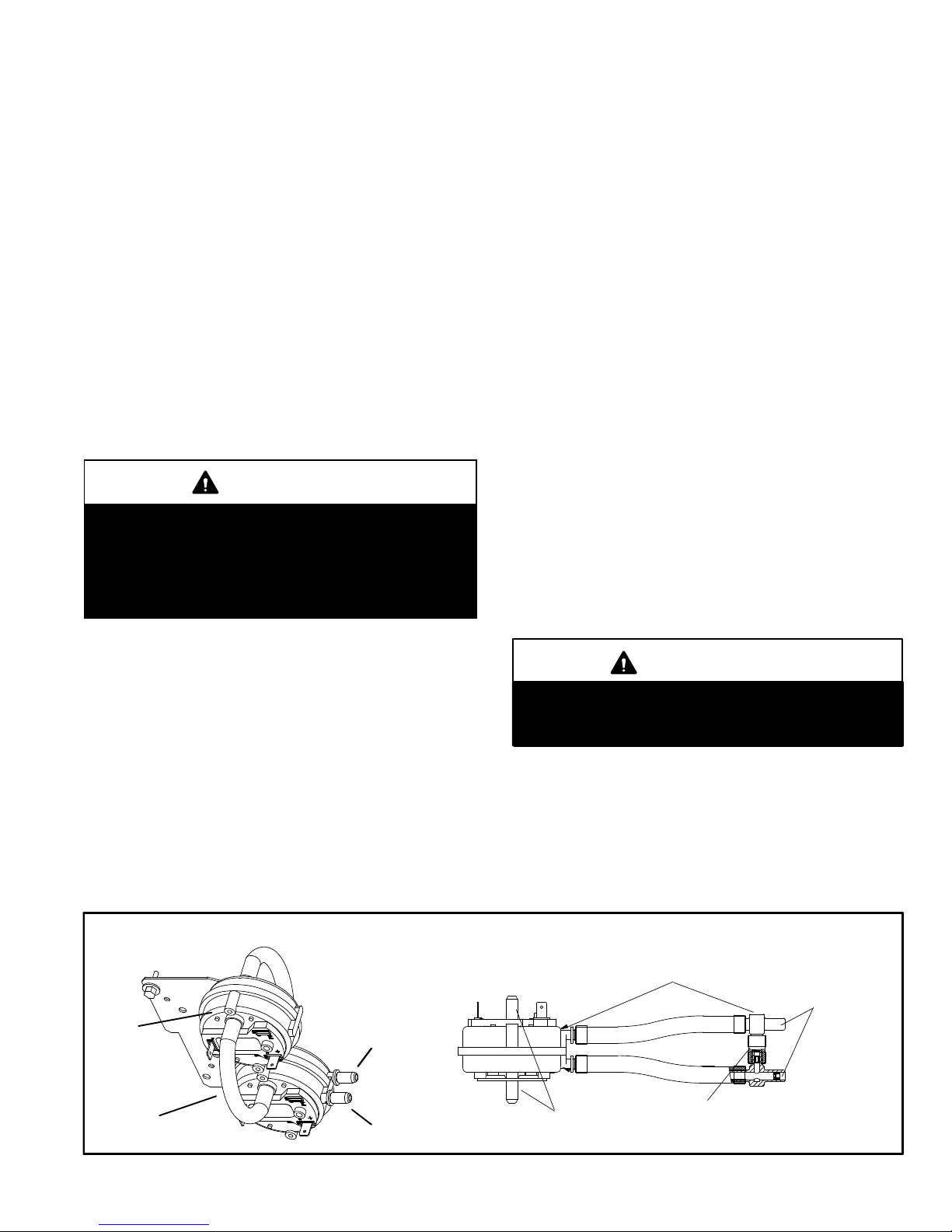
Page 33
6. Backup Secondary Limit Control (S113)
(G71MPP−090, 110, 135 only)
Backup secondary limit control S113 is a N.C. auto−reset
switch located on the combustion air inducer. S113 acts as
a backup to primary limit S10 in the event of an indoor blower failure. S113 contacts open when temperature on the
CAI reaches 142°.
7. Gas Valve (GV1)
The G71MPP uses a variable capacity gas valve (figure 35)
and is applicable for single stage, two−stage or varaiable
capacity settings. See Thermostat selection modes" in the
ignition control section (section A− subsection 4.) for more
details The valve is internally redundant to assure safety
shut−off. If the gas valve must be replaced, the same type
valve must be used.
A 24VAC 2−pin plug and gas control switch are located on the
valve. 24V applied to the pins enables valve operation.
Inlet and outlet pressure taps are located on the valve.
LPG change over kits are available from Lennox. Kits include
burner orifices and an LP gas valve.
DANGER
Danger of explosion.
There are circumstances in which odorant used with
LP/propane gas can lose its scent. In case of a leak,
LP/propane gas will settle close to the floor and may
be difficult to smell. An LP/propane leak detector
should be installed in all LP applications.
The burner box is sealed and operates under a negative
pressure. A pressure hose is connected from the burner
box to the gas valve. The gas valve senses the pressure in
the burner box and uses that to set the maximum manifold
pressure while the pressure switch with pressure conditioning device adjusts the gas flow. This will compensate
for different vent configurations which can greatly affect the
rate of the unit.
8. Variable Speed Combustion Air Inducer
Pressure Switch (S18)
All G71MPP units are equipped with two pressure switch assemblies (one dual switch and one single switch see figure
14) to allow for multiple unit installations without any hose
routing changes. The pressure switches serve four func-
tions. First they establish calibration points for the vent calibration routine. The combustion air inducer’s speed at a given firing rate is a function of the vent system restriction. The
calibration routine establishes the inducer speed required to
make low and high fire switches for a given vent pipe installation and interpolates the speeds required to achieve all intermediate rates between these two points. The pressure
conditioning device (low fire) and the high fire switch are utilized for this function. The setting for low−fire switch on dual
assembly is such that it does not normally enter into the vent
calibration routine.
Second, the switches prove combustion air inducer operation by sensing a vacuum energizing the control circuit and
allowing ignition. The low fire pressure switch provides this
function.
Thirdly the switches interrupt the combustion process in the
event vent outlet or combustion air intake blockage. Both
switches provide this function.
Finally the switches interrupt the combustion process if the
condensate drainage system becomes blocked to the point
the condensate level builds up in the cold end header box/
secondary coil or vent system. Both switches serve this
function.
If either switch assembly (dual or single) is to be replaced,
replace the entire assembly. Individual switch components
can not be replaced.
WARNING
The pressure switch is a safety shut−down control
in the furnace and must not be jumpered for any
reason other than troubleshooting.
To troubleshoot the pressure switches, temporarily jumper
them. The unit will not fire with the switches jumpered. Therefore, the pressure switches must be bypassed after the combustion air inducer is activated. This will determine if the pressure switches and furnace are operating properly. However,
this may not indicate if the sealed combustion system is operating properly.
FIGURE 14
DUAL COMBUSTION AIR PRESSURE SWITCH
high fire
low fire
positive
pressure
negative
pressure
SINGLE COMBUSTION AIR PRESSURE SWITCH
operating pressure
to valve
system pressure across
heat exchanger
pressure conditioning device
Page 34

Page 34
Vent Calibration
The vent calibration sequence establishes furnace operating parameters in a specific installation. The integrated
control board runs the calibration and may be repeated as
necessary to maintain proper furnace operation. Prior to
calibration, all duct work (and returns) vent pipe and condensate trap (primed) must be connected.
If calibration is successful the data is stored in memory and
will be used to determine furnace operation and maintain
parameters during heat call. If calibration is not successful,
the integrated control will proceed to a 5 minute delay and
signal the appropriate code. After the 5 minute delay the
calibration will be repeated 4 more times with a 5 minute
delay in between. If still unsuccessful after the 4 trials (total
5) the integrated control will go into a 1 hour soft lockout.
Calibration may be initiated by:
S Initial call for heat
S Cycling main power off / on and then call for heat
S Venting conditions change (affecting high and low
pressure switch operation)
S Ramp down low fire switch check failed (calibration
will follow next call for heat)
S The service technician (by pressing the push button
found on the integrated control until the control cycles
through to Field Test Mode")
The integrated control will do the following during
calibration:
1− Verify both low pressure switch and high pressure
switch are open. If either are closed log error and end
calibration.
2− Start inducer at a predetermined low RPM (1600).
3− After a 7.5 second delay and if the low pressure
switch is still open, increase the RPM by 250. If after a 5
second delay the low pressure switch is still open, repeat steps 1, 2 and 3.
4− Decrease RPM by 50, wait 5 seconds and look for
the low pressure switch to open. Repeat this step until
it is closed.
5− Keep this RPM as RPM1.
6− Increase RPM to 1250. Wait 5 seconds.
7− Check high pressure switch, if open, increase RPM
by 250. Repeat this step until closed.
8− Decrease RPM by 50, check after 5 seconds. Re-
peat this step until switch is open.
9− Keep this RPM as RPM2.
10− Set RPM to 0. End calibration.
NOTE − If after a successful calibration and a heat call
is present the integrated control will by−pass the prepurge state and go straight into ignitor warm up.
After calibration, the integrated control stores the RPM1
and RPM2 values. The low fire (40%) and high fire (100%)
RPM points are calculated by adding margin values to the
RPM1 and RPM2 values.
The integrated control also initiates a low fire switch check
at the end of a normal heating cycle described below. If this
check fails the pressure switch calibration will follow on the
next call for heat.
1− The inducer runs 15 seconds at the last firing rate
before the heat call ended.
2− Inducer runs at 40% firing rate RPM (RPM1 + low
pressure switch open RPM margin value).
3− If low pressure switch is open, set flag for calibration
on next call for heat. Turn inducer off until next call for
heat.
4− If low pressure switch is closed move inducer speed
to RPM1. Allow 5 seconds for stabilization.
5− If low pressure switch opens turn off inducer. No further action.
6− If low pressure switch is still closed, decrease inducer speed 1/2 of the low pressure switch open RPM
margin. Allow 5 seconds to stabilize.
7− If low pressure switch is open turn off inducer. No further action.
8− If low pressure switch is still closed, set flag for calibration on next call for heat and turn off inducer.
Measuring pressure differential Figure 15
Checks of pressure differential can aid in troubleshooting.
When measuring the pressure differential, readings should be
taken at the pressure switch. Lack of differential usually indicates problems in the intake or exhaust piping, b u t may indicate problems in the heat exchanger, condensing coil,
header boxes, combustion inducer or other components.
The differential pressure is the difference in pressure measured across the cold end header box orifice.
Page 35
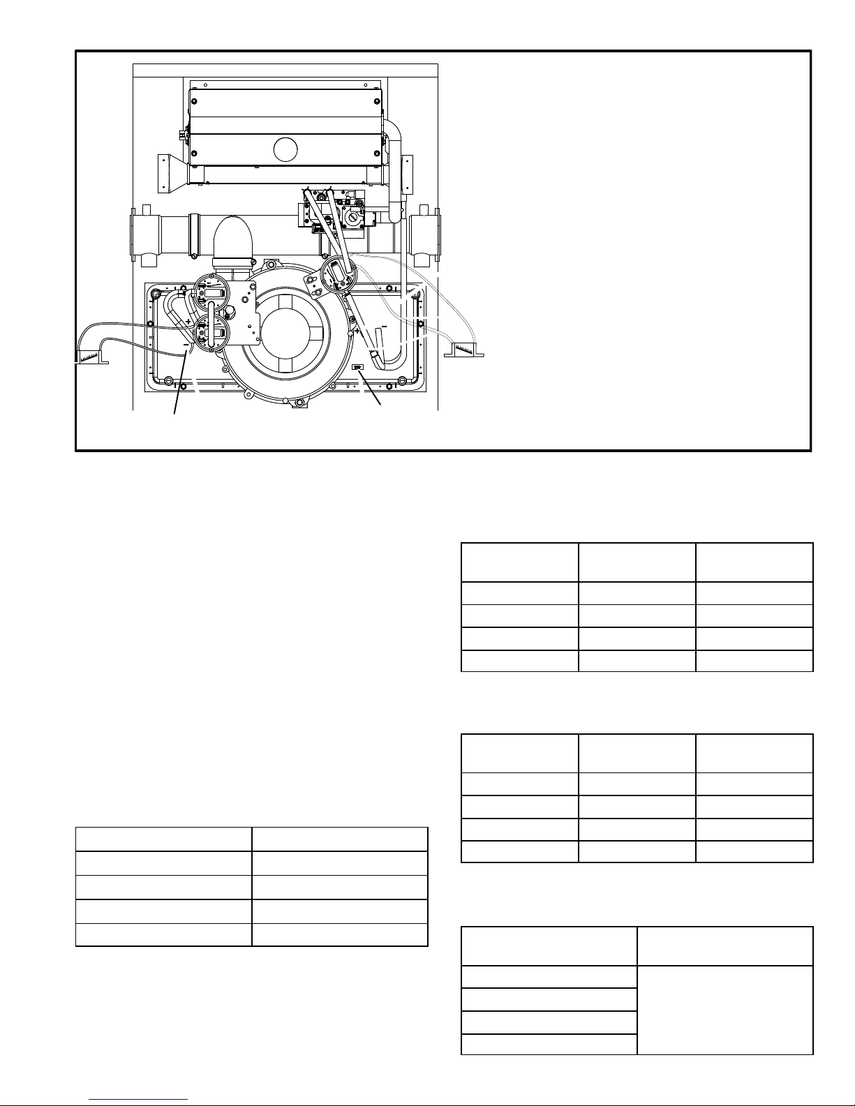
Page 35
FIGURE 15
negative and positive taps
(same on other side)
orifice
1 − Remove thermostat demand and allow unit to cycle off.
2 − Install a tee in the negative (−) line and a tee in the positive (+)
line running from the lower pressure switch to the cold end
header box.
3 − Install a manometer with hose from the negative (−) side of
the manometer to the tee installed in the negative (−) line
and with hose from the positive (+) side of the manometer
to the tee in the positive (+) line.
NOTE − Both sides of the cold end header box are negative.
However the (+) port reads less negative pressure than the (−)
port.
4 − Operate unit and observe manometer reading.
Readings will change as heat exchanger warms.
a. Take one reading immediately after start-up.
b. Take a second reading after unit has reached steady
state (approximately 5 minutes). This will be the pressure
differential.
The pressure differential should be greater
than those listed in tables 31 and 32.
5 − Remove thermostat demand and allow to cycle off.
6 − Remove manometer and tee’s. Reinstall combustion air
sensing hoses to the pressure switch.
7 − Repeat steps 1 through 6 for the single pressure switch
with pressure conditioning device. Tee into both hoses from
the pressure switch to the gas valve and install manometer.
Readings should be greater than those shown in table 33.
Duel Pressure Switch
Single Pressure Switch with Pressure Conditioning Device
+
−
The CAI is installed on the cold end header box. The cold
end header box is a single piece made of hard plastic.
The box has an internal channel where the combustion
air inducer creates negative pressure at unit start up. The
channel contains an orifice used to regulate flow created
by the CAI. The box has pressure taps for the CAI pressure switch hoses.
The dual pressure switches measure the pressure differential across the CAI orifice (difference in the channel
and cold end header box). The single pressure switch
measures differential across the burner box and channel. A window is provided on the bottom right hand side of
the cold end header box to indicate orifice size. See figure 15. See table 30 for orifice size per unit. If replace-
ment is necessary the gaskets used to seal the box to
the vestbule panel and the CAI to the box, must also
be replaced.
TABLE 30
G71MPP Unit
C.A.I. Orifice Size
−070 0.938"
−090 1.063"
−110 1.250"
−135 1.625"
TABLE 31
Dual Pressure Switch
0’ to 7500’
G71MPP Unit
Set Point
High Fire
Set Point
Low Fire
−070 1.37" 0.30"
−090 1.22" 0.25"
−110 1.32" 0.20
−135 0.83" 0.15"
TABLE 32*
Dual Pressure Switch
7501’ to 10,000’
G71MPP Unit
Set Point
High Fire
Set Point
Low Fire
−070 1.22" 0.30"
−090 1.02" 0.25"
−110 1.12" 0.20"
−135 0.63" 0.15"
*Unit may require conversion kit at this altitude. See High Altitude
table.
TABLE 33
Single Pressure Switch
G71MPP Unit
Set Point
High Fire
−070
.27"
−090
−110
−135
Page 36

Page 36
II−PLACEMENT AND INSTALLATION
TABLE 34
OUTDOOR TERMINATION KITS AND CORRESPONDING EQUIVALENCIES
UNIT
MODEL
VENT
PIPE
DIA.
(in.)
Vent Pipe Length Equivalency (feet)
Outdoor Exhaust Accel-
erator
(Dia. X
Length)
Outdoor Exhaust Accel-
erator
(Dia. X
Length)
1−1/2"
Concentric
Kit
2"
Concentric
Kit
3"
Concentric
Kit
2" Wall Plate
Kit
3" Wall Plate
Kit
2" Wall
Ring Kit
1−1/2" X 12"
2" X 12" 71M80 69M29 60L46
22G44
30G28
44J40
81J20
15F74
36B−070
2 4
Not
Allowed
12
Not
Allowed
Not
Allowed
4 4* 4
2−1/2 5
Not
Allowed
15
Not
Allowed
Not
Allowed
5 5* 5
3 8
Not
Allowed
24
Not
Allowed
Not
Allowed
8 8* 8
4 14
Not
Allowed
42
Not
Allowed
Not
Allowed
14 14* 14
60C−090
2
Not
Allowed
1
Not
Allowed
3 3
Not
Allowed
1 1**
2−1/2
Not
Allowed
2
Not
Allowed
6 6
Not
Allowed
2 2**
3
Not
Allowed
2
Not
Allowed
6 6
Not
Allowed
2 2**
4
Not
Allowed
4
Not
Allowed
12 12
Not
Allowed
4 4**
60C−110
2−1/2
Not
Allowed
2
Not
Allowed
6 6
Not
Allowed
2 2
3
Not
Allowed
2
Not
Allowed
6 6
Not
Allowed
2 2
4
Not
Allowed
4
Not
Allowed
12 12
Not
Allowed
4 4
60D−135
3
Not
Allowed
6
Not
Allowed
Not
Allowed
15
Not
Allowed
6
Not
Allowed
4
Not
Allowed
10
Not
Allowed
Not
Allowed
25
Not
Allowed
10
Not
Allowed
*Requires field−provided and installed 1−1/2" exhaust accelerator.
Proposed vent pipe size : ______
Termination kit catalog number : _____________
Vent pipe equivalency value from table 34: ______
Total number of 90° elbows required (indoors and outdoors)
______ X 5 = ______ equivalent feet of pipe
Total number of 45° elbows required (indoors and outdoors)
______ X 2.5 = ______ equivalent feet of pipe
Linear feet of straight pipe required : ______
Add equivalent feet of vent pipe listed in
steps 2 through 5.
Step 1
Step 2
Step 3
Step 4
Step 5
Step 6
If the total is equal to, or less than, the allowable maximum given in table 36, the proposed pipe size is acceptable. If the
total exceeds the maximum allowed vent pipe length, repeat the process above using the next larger diameter pipe until
an acceptable total is achieved.
NOTE − In Direct Vent systems, total the equivalent length of either the exhaust OR intake piping run, depending upon which
will be LONGER. Intake and exhaust pipe diameter must be the same size and must be terminated in the same pressure
zone. Intake and exhaust pipe should be roughly the same length.
Equivalent Feet
TOTAL
FIGURE 16
Page 37

Page 37
A−Vent Piping Guidelines
The G71MPP can be installed only as a Direct Vent gas
central furnace.
NOTE − In Direct Vent installations, combustion air is taken
from outdoors and flue gases are discharged outdoors.
Intake and exhaust pipe sizing −− Size pipe according to
tables 35 and 36. Table 35 lists the minimum equivalent
vent pipe lengths permitted. Table 36 lists the maximum
equivalent pipe lengths permitted.
Maximum vent length is defined as:
Total length (linear feet) of pipe,
Plus Equivalent length (feet) of fittings,
Plus Equivalent length (feet) of termination.
NOTE − Include ALL pipe and ALL fittings, both indoors
and outdoors. Measure equivalent length of intake and
exhaust pipe separately. Use the greater of the two
lengths to determine vent pipe diameter to be used for
both intake and exhaust.
Regardless of the diameter of pipe used, the standard roof
and wall terminations described in section Exhaust Piping
Terminations should be used. Exhaust vent termination
pipe is sized to optimize the velocity of the exhaust gas as
it exits the termination. Refer to table 37.
NOTE − The exhaust pipe should be offset a minimum of 12
inches to avoid the possibility of water droplets being released from the exhaust termination. The minimum exhaust vent length is 15 ft. Shorter exhaust vent lengths may
result in the discharge of water droplets from the exhaust
termination, in spite of the 12−inch vertical offset. See figure
17.
Each 90° elbow (including those provided with the furnace)
of any diameter is equivalent to 5 feet (1.52m) of vent pipe
of the same diameter. Two 45° elbows are equivalent to
one 90° elbow of the same diameter. One 45° elbow is
equal to 2.5 feet (.76m) of vent pipe of the same diameter.
In some applications which permit the use of several different sizes of vent pipe, a combination vent pipe may be
used. Contact Lennox’ Application Department for assistance in sizing vent pipe in these applications.
FIGURE 17
Exhaust Pipe Offset
12" Min.
12" Min.
12" Min.
12" Min.
Upflow and Downflow Application
Rooftop Termination
Upflow and Downflow Application
Side Wall Termination
Horizontal Application
Rooftop Termination
Horizontal Application
Side Wall Termination
Page 38

Page 38
NOTE − The flue collar on all models is sized to accommodate 2" Schedule 40 flue pipe. When vent pipe which is
larger than 2" must be used in an upflow application, a 2"
elbow must be applied at the flue collar in order to properly transition to the larger diameter flue pipe. This elbow
must be added to the elbow count used to determine acceptable vent lengths. Assign an equivalent feet value to
this elbow according to the larger size pipe being used.
Contact the Application Department for more information
concerning sizing of vent systems which include multiple
pipe sizes.
Use the following steps to correctly size vent pipe diameter.
Refer to Vent Pipe Size Determination Worksheet
Figure 16.
1 − Determine the vent termination and its corresponding
equivalent feet value according to table 34.
2 − Determine the number of 90° elbows required for both
indoor and outdoor (e.g. snow riser) use. Calculate the
corresponding equivalent feet of vent pipe.
3 − Determine the number of 45° elbows required for both
indoor and outdoor use. Calculate the corresponding
equivalent feet of vent pipe.
4 − Determine the length of straight pipe required.
5 − Add the total equivalent feet calculated in steps 1
through 4 and compare that length to the maximum
values given in table 36 for the proposed vent pipe diameter. If the total equivalent length required exceeds
the maximum equivalent length listed in the appropriate table, evaluate the next larger size pipe.
IMPORTANT
Do not use screens or perforated metal in exhaust or
intake terminations. Doing so will cause freeze−ups
and may block the terminations.
TABLE 35
MINIMUM VENT PIPE LENGTHS
G71MPP
MODEL
MIN. EQUIV.
VENT LENGTH
EXAMPLE
070, 090
15 ft.*
5 ft. plus 2 elbows of 2", 2−1/2", 3"
or 4" diameter pipe
110**
5 ft. plus 2 elbows of 2−1/2" 3" or 4"
diameter pipe
135***
5 ft. plus 2 elbows of 3" or 4"
diameter pipe
*Any approved termination may be added to the minimum equivalent length
listed.
**G71MPP−60C−110 must have 90° street ell (supplied) installed directly into
unit flue collar.
***G71MPP−60D−135 must have 3" to 2" reducing ell (supplied) installed directly into unit flue collar.
TABLE 36
MAXIMUM VENT PIPE LENGTHS
ALTITUDE
G71MPP
MODEL
MAXIMUM EQUIVALENT VENT
LENGTH FEET
2"
PIPE
2−1/2"
PIPE
3"
PIPE4"PIPE
0 − 7500
(0 − 2286 m)
070 75 135 150 250
090 50 100 125 225
110* 20 60 125 200
135** n/a n/a 125 180
7501 − 10000
(2287 − 3048 m)
070 60 125 150 250
090 25 60 125 225
110* n/a 40 90 200
135** n/a n/a 70 180
n/a −− Not allowed.
*G71MPP−60C−110 must have 90° street ell (supplied) installed directly into
unit flue collar.
**G71MPP−60D−135 must have 3" to 2" reducing ell (supplied) installed directly
into unit flue collar.
NOTE − Elbows and pipe required for vent terminations must be added
when calculating equivalent vent length.
B−Joint Cementing Procedure
All cementing of joints should be done according to the
specifications outlined in ASTM D 2855.
WARNING
DANGER OF EXPLOSION!
Fumes from PVC glue may ignite during system
check. Allow fumes to dissipate for at least 5 minutes
before placing unit into operation.
1 − Measure and cut vent pipe to desired length.
2 − Debur and chamfer end of pipe, removing any ridges
or rough edges. If end is not chamfered, edge of pipe
may remove cement from fitting socket and result in a
leaking joint.
3 − Clean and dry surfaces to be joined.
4 − Test fit joint and mark depth of fitting on outside of pipe.
5 − Uniformly apply liberal coat of PVC primer for PVC or
use a clean dry cloth for ABS to clean inside socket
surface of fitting and male end of pipe to depth of fitting
socket.
NOTE − Furnace flue collar and air inlet fitting are both
ABS pipe. Use transition solvent cement when joining
ABS pipe to PVC pipe.
6 − Promptly apply solvent cement to end of pipe and in-
side socket surface of fitting. Cement should be applied lightly but uniformly to inside of socket. Take
care to keep excess cement out of socket. Apply second coat to end of pipe.
NOTE − Time is critical at this stage. Do not allow primer to dry before applying cement.
Page 39

Page 39
7 − Immediately after applying last coat of cement to pipe,
and while both inside socket surface and end of pipe
are wet with cement, forcefully insert end of pipe into
socket until it bottoms out. Turn PVC pipe 1/4 turn during assembly (but not after pipe is fully inserted) to distribute cement evenly. DO NOT turn ABS or cellular
core pipe.
NOTE − Assembly should be completed within 20 seconds after last application of cement. Hammer blows
should not be used when inserting pipe.
8 − After assembly, wipe excess cement from pipe at end
of fitting socket. A properly made joint will show a
bead around its entire perimeter. Any gaps may indicate a defective assembly due to insufficient solvent.
9 − Handle joints carefully until completely set.
C−Venting Practices
The thickness of construction through which vent pipes
may be installed is 24" (610mm) maximum and 3/4"
(19mm) minimum. If a G71MPP furnace replaces a furnace
which was commonly vented with another gas appliance,
the size of the existing vent pipe for that gas appliance must
be checked. Without the heat of the original furnace flue
products, the existing vent pipe is probably oversized for
the single water heater or other appliance. The vent should
be checked for proper draw with the remaining appliance.
1. Use recommended piping materials for exhaust pip-
ing.
2. Secure all joints so that they are gas-tight using ap-
proved cement.
Suspend piping using hangers at a minimum of every 5
feet (1.52m) for schedule
40 PVC and every 3 feet
(.91m) for ABS−DWV, PVC−
DWV, SPR−21 PVC, and
SDR−26 PVC piping. A suitable hanger can be fabricated by using metal or
plastic strapping or a large
wire tie.
3. In areas where piping penetrates joists or interior
walls, hole must be large enough to allow clearance on
all sides of pipe through center of hole using a hanger.
4. Isolate piping at the point where it exits the outside wall
or roof in order to prevent transmission of vibration to
the structure.
5. When furnace is installed in a residence where unit is
shut down for an extended period of time, such as a
vacation home, make provisions for draining condensate collection trap and lines.
Exhaust Piping (Figures 19 and 20)
NOTE − A 2" diameter street ell is located on the blower
deck of 60C−110 units. Street ell must be
glued with ABS
solvent cement directly into the unit flue collar. See figure
19. A 3" to 2" reducing ell is located on the blower deck of
the 60D−135 units. In upflow or downflow applica-
tions, the reducing ell must be
glued with ABS solvent
cement directly into the unit flue collar.
1. Choose the appropriate side for venting in upflow or
downflow positions. Exhaust piping exits from the top
of the unit in horizontal air discharge applications.
Glue the field−provided exhaust vent pipe (or provided
street ell or reducing ell in upflow or downflow applications) to the flue collar. All PVC cement joints should
be made according to the specifications outlined in
ASTM D 2855. Refer to pipe and fittings specifications
and gluing procedures.
IMPORTANT
Exhaust piping and condensate trap must be
installed on the same side of the unit in upflow and
dowflow applications or use alternate drain kit
76M20.
2. All horizontal runs of exhaust pipe must slope back toward unit. A minimum of 1/4" (6mm) drop for each 12"
(305mm) of horizontal run is mandatory for drainage.
Horizontal runs of exhaust piping must be supported every 5 feet (1.52m) using hangers.
NOTE − Exhaust piping should be checked carefully to
make sure there are no sags or low spots.
3. On the opposite side of the cabinet, glue the provided
2" vent plug into the unused flue collar.
4. Route piping to outside of structure. Continue with
installation following instructions given in piping termination section.
CAUTION
Do not discharge exhaust into an existing stack or
stack that also serves another gas appliance. If vertical discharge through an existing unused stack is required, insert PVC pipe inside the stack until the end
is even with the top or outlet end of the metal stack.
CAUTION
The exhaust vent pipe operates under positive pressure and must be completely sealed to prevent leakage of combustion products into the living space.
FIGURE 18
STRAPPING
(metal, plastic
or large wire
ties)
Page 40
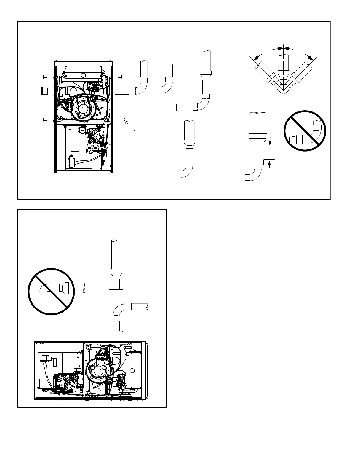
Page 40
VENT PLUG
(Must be
glued in
place)
PLUG
PLUG
TYPICAL EXHAUST PIPE CONNECTIONS AND CONDENSATE TRAP INSTALLATION
IN UPFLOW OR DOWNFLOW DIRECT VENT APPLICATIONS
(Right−Hand Exit in Upflow Application Shown)
FIGURE 19
CONDENSATE
TRAP
(Must be installed
on same side as
exhaust piping)
PLUG
*2" diameter street elbow provided.
**3" to 2" diameter reducing elbow provided.
G71MPP−135 with
3" OR 4" vent pipe
2"**
2"
G71MPP−070,
or −090 with
2−1/2", 3", or 4"
vent pipe
3" dia. pipe***
TRANSITION
(use only if 4"
pipe is
required)
4"
2"
2" dia. pipe
2−1/2",
3", OR
4"
TRANSITION
2"
2"
G71MPP−110 with
2−1/2", 3", OR 4"
vent pipe
2"*
TRANSITION
2−1/2",
3", OR
4"
2"
2"
or
45°
MAX
45°
MAX
SIDE VIEW
*** Max 2" pipe length between reducing
elbow and transition when 4" pipe is used.
FIGURE 20
TYPICAL EXHAUST PIPE CONNECTIONS
HORIZONTAL DIRECT VENT APPLICATIONS
(Horizontal Right−Hand Air Discharge Application Shown)
2"
2"
2"
2" dia.
pipe*
2−1/2",
3", OR
4"
DO NOT transition from
smaller to larger pipe
size in horizontal runs.
TRANSITION
−36B−070
−36C−090
−60C−090
−60C−110*
−60D−135*
−36B−070
−36C−090
−60C−090
*2" maximum length
for −135 only.
Intake Piping
The G71MPP furnace may be installed only in direct vent
applications.
The G71MPP unit is designed for either left−side or right−
side air intake connections in either upflow or downflow applications. In horizontal applications, air intake must be
brought in through the top. Intake air piping is independent
of exhaust piping.
Page 41

Page 41
TYPICAL AIR INTAKE PIPE CONNECTIONS
UPFLOW OR DOWNFLOW DIRECT VENT APPLICATIONS
(Right−Hand Exit in Upflow Application Shown)
FIGURE 21
PLUG
(Must be
glued in
place)
*Limit pipe length to 4" in
G71MPP−135 applications.
−36B−070
−36C−090
−60C−090
−36B−070
−36C−090
−60C−090
−60C−110
−36B−070
−36C−090
−60C−090
−60C−110
−60D−135*
2
2
2
2
2
2
2−1/2",
3" OR
4
TRANSITION
2"*
TRANSITION
2−1/2",
3" OR
4
FIGURE 22
TYPICAL AIR INTAKE PIPE CONNECTIONS
HORIZONTAL DIRECT VENT APPLICATIONS
(Horizontal Right−Hand Air Discharge Application Shown)
2”*
2”
2”
2”
TRANSITION
TRANSITION
2”
2−1/2”,
3” OR 4”
2−1/2”,
3” OR 4”
*Limit pipe
length to 4" in
−135 applications.
2”
−36B−070
−36C−090
−60C−090
−60C−110
−60D−135*
−36B−070
−36C−090
−60C−090
−60C−110
−36B−070
−36C−090
−60C−090
2”
Page 42

Page 42
FIGURE 23
VENT TERMINATION CLEARANCES
FOR INSTALLATIONS IN THE USA AND CANADA*
A − Clearance above grade − 12 in. (305mm) minimum.
B − Clearance to window or door that may be opened −
for vent installations in USA − 12 in. (305mm) minimum.
for vent installations in Canada − 12 in. (305mm) minimum
for appliances 100,000 Btuh (30 kW);
36 in. (0.9m) minimum for appliances > 100,000 Btuh (30
kW).
C − Do not position terminations directly under roof eaves.
D − Clearance to electric meters, gas meters, regulators, and
relief equipment −
for vent installations in USA − 48 in (1219mm) minimum.
for vent installations in Canada − see current edition of CSA
B149 Code.
E − Clearance to non−mechanical air supply inlet or outlet
for vent installations in USA − 48 in. (1219mm) minimum
horizontal and below, 12 in. (305mm) minimum above.
for vent installations in Canada − 12 in. (305mm) minimum
for appliances 100,000 Btuh (30 kW);
36 in. (0.9m) minimum for appliances > 100,000 Btuh (30
kW).
F − Clearance to mechanical air supply inlet −−
for vent installations in USA − 36 in. minimum (914mm).
G − Clearance to mechanical air supply inlet −−
for vent installations in Canada − 72 in. (1829mm) minimum.
H − Do not point terminations into recessed areas such as win-
dow wells, stairwells or alcoves.
J − Do not position terminations directly above a public walk-
way.
* Note −
(I) Dimensions are from the current edition of The National Fuel Gas Code − ANSI-Z223.1/NFPA 54 for USA installations. In Canada, refer to current edition of CSA B149 installation codes. Local codes or regulations may require different
clearances.
less than
10 ft (3.048M)
C
D
D
E
F
G
(II) In Non-Direct Vent installations, combustion air is taken from indoors and the flue gases are discharged to the outdoors.
− G71MPP VENT TERMINATION
− AIR INLET OF OTHER APPLIANCE
Page 43

Page 43
Details of Intake and Exhaust Piping Terminations for
Direct Vent Installations
NOTE − In Direct Vent installations, combustion air is taken
from outdoors and flue gases are discharged to outdoors.
Intake and exhaust pipes may be routed either horizontally
through an outside wall or vertically through the roof. In attic or closet installations, vertical termination through the
roof is preferred. Figures 24 through 32 show typical terminations.
1. Exhaust and intake exits must be in same pressure
zone. Do not exit one through the roof and one on the
side. Also, do not exit the intake on one side and the
exhaust on another side of the house or structure.
2. Intake and exhaust pipes should be placed as close
together as possible at termination end (refer to illustrations). Maximum separation is 3" (76mm) on roof
terminations and 6" (152mm) on side wall terminations.
3. If necessary, install a field−provided transition to adapt
larger vent pipe size to termination pipe size.
4. On roof terminations, the intake piping should terminate straight down using two 90° elbows (See figure
24).
5. Exhaust piping must terminate straight out or up as
shown. In rooftop applications, a reducer may be required on the exhaust piping at the point where it exits
the structure to improve the velocity of exhaust away
from the intake piping. See table 37.
NOTE − Care must be taken to avoid recirculation of
exhaust back into intake pipe.
6. On field supplied terminations for side wall exits, exhaust piping should extend a maximum of 12 inches
(305mm) beyond the outside wall unless supported.
Intake piping should be as short as possible. See figure 25.
7. On field supplied terminations, the end of the exhaust
pipe must extend a minimum of 8" (203mm) beyond
the end of the intake pipe.
8. If intake and exhaust piping must be run up a side wall
to position above snow accumulation or other obstructions, piping must be supported every 3 ft. (.9m)
as shown in figure 18. Refer to figure 28 for proper
piping method. In addition, wall termination kit must
be extended for use in this application. See figure 31.
When exhaust and intake piping must be run up an
outside wall, the exhaust piping must be terminated
with pipe sized per table 37. The intake piping may be
equipped with a 90° elbow turndown. Using turndown
will add 5 feet (1.5m) to the equivalent length of the
pipe.
9. Based on the recommendation of the manufacturer, a
multiple furnace installation may use a group of up to
four termination kits assembled together horizontally,
as shown in figure 30.
TABLE 37
EXHAUST PIPE TERMINATION SIZE REDUCTION
G71MPP
MODEL
Exhaust Pipe Size Termination Pipe Size
070 2", 2−1/2", 3" or 4" 1−1/2"
090 2", 2−1/2", 3" or 4" 2"
110 2−1/2", 3" or 4" 2"*
135 3" or 4" 2"*
*Approved 3" concentric termination kit terminates with 2−5/8" ID pipe.
FIGURE 24
DIRECT VENT ROOF TERMINATION KIT
(15F75 or 44J41)
UNCONDITIONED
ATTIC SPACE
1/2" (13) FOAM
INSULATION IN
UNCONDITIONED
SPACE
SIZE TERMINATION
PIPE PER TABLE 37.
3(76) MAX.
12" (305) ABOVE
AVERAGE SNOW
ACCUMULATION
3" (76) OR
2" (51) PVC
PROVIDE SUPPORT
FOR INTAKE AND
EXHAUST LINES
8" (203) MIN
Inches(mm)
FIGURE 25
1/2" (13) ARMAFLEX
INSULATION IN
UNCONDITIONED SPACE
1−1/2" (38) PVC
12" (305) MAX.
(unless supported)
6" (152)
MAXIMUM
2" (51) PVC
COUPLING
8" (203)
MINIMUM
OUTSIDE
WALL
Inches (mm)
TOP VIEW WALL RING KIT
(15F74)
1/2" (13)
ARMAFLEX
INSULATION
FIELD−
PROVIDED
REDUCER MAY
BE REQUIRED
TO ADAPT
LARGER VENT
PIPE SIZE TO
TERMINATION
Page 44
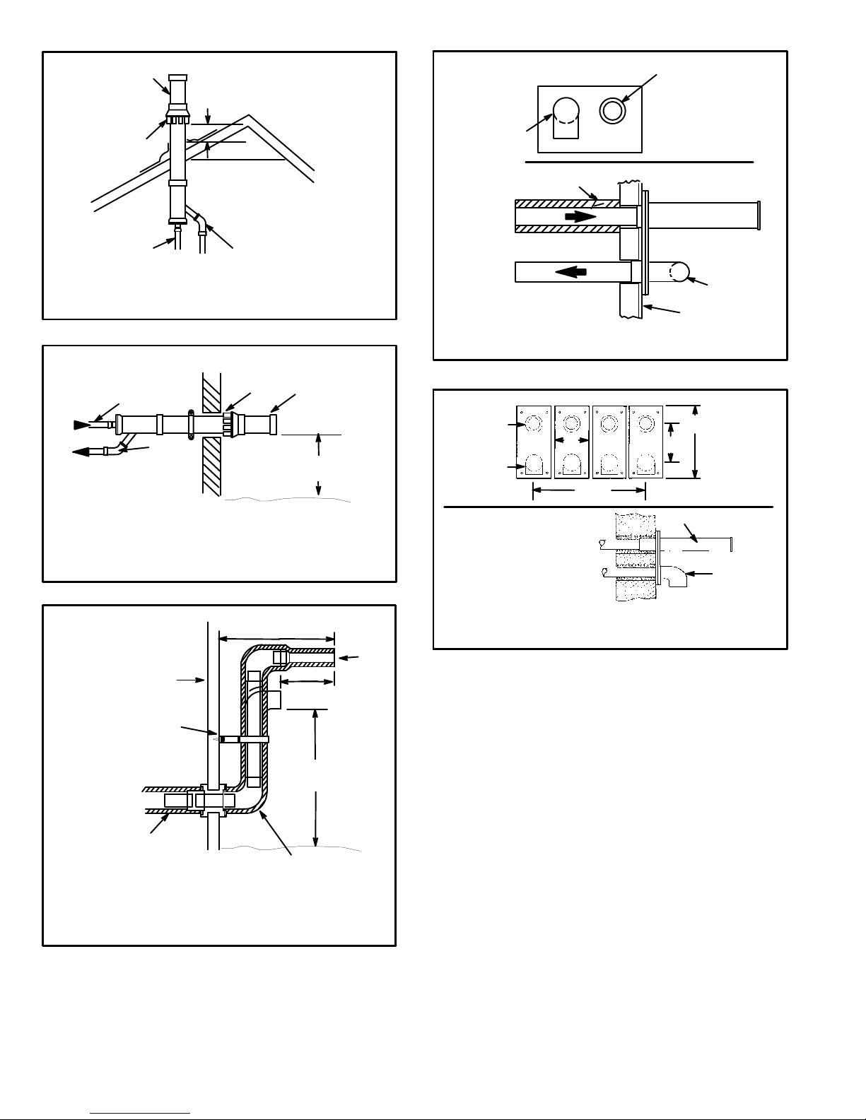
Page 44
FIGURE 26
12" (305) ABOVE
AVERAGE SNOW
ACCUMULATION
EXHAUST
EXHAUST
TERMINATION
INTAKE
TERMINATION
INTAKE
Inches (mm)
DIRECT VENT CONCENTRIC ROOFTOP TERMINATION
(71M80, 69M29 or 60L46)
FIELD−PROVIDED
REDUCER MAY BE REQUIRED
TO ADAPT LARGER VENT
PIPE SIZE TO TERMINATION
FIGURE 27
EXHAUST
EXHAUST
TERMINATION
INTAKE
TERMINATION
INTAKE
12" (305) Min.
above grade.
Inches (mm)
DIRECT VENT CONCENTRIC WALL TERMINATION
(71M80, 69M29 or 60L46)
FIELD−PROVIDED
REDUCER MAY
BE REQUIRED TO
ADAPT LARGER
VENT PIPE SIZE
TO TERMINATION
FIGURE 28
See venting table 36 for maximum venting lengths with this arrange-
ment.
12" (305) ABOVE
AVERAGE SNOW
ACCUMULATION
UNCONDITIONED
SPACE
12" (305) MAX. for 2" (51)
(unless supported)
8 (203)
MIN.
1/2" (13) FOAM
INSULATION
1/2" (13) FOAM
INSULATION IN
UNCONDITIONED
SPACE
PROVIDE SUPPORT
FOR INTAKE AND
EXHAUST LINES EVERY
36" (914)
OUTSIDE WALL
Inches(mm)
SIDE VIEW
DIRECT VENT WALL RING TERMINATION
(15F74)
SIZE
TERMINATION
PIPE PER
TABLE 37.
FIELD−PROVIDED
REDUCER MAY
BE REQUIRED TO
ADAPT LARGER
VENT PIPE SIZE
TO TERMINATION
FIGURE 29
1/2" (13) Foam Insulation
in Unconditioned Space
EXHAUST VENT
INTAKE VENT
WITHOPTIONAL
ELBOW
OUTSIDE WALL
EXHAUST VENT
INTAKE
VENT
WITH OPTIONAL
ELBOW
Front View
Side View
Inches (mm)
FIELD−
PROVIDED
REDUCER MAY
BE REQUIRED
TO ADAPT
LARGER VENT
PIPE SIZE TO
TERMINATION
DIRECT VENT WALL TERMINATION KIT
(22G44, 44J40, 30G28 or 81J20)
FIGURE 30
EXHAUST
VENT
INTAKE
VENT
WITH OPTIONAL
ELBOW
5−1/2"
(140)
Front View
12"
(305)
5"
(127)
18" MAX.
(457)
EXHAUST VENT
OPTIONAL VENT TERMINATION FOR MULTIPLE UNIT
INSTALLATION OF DIRECT VENT WALL TERMINATION KIT
Inches (mm)
Side View
Page 45
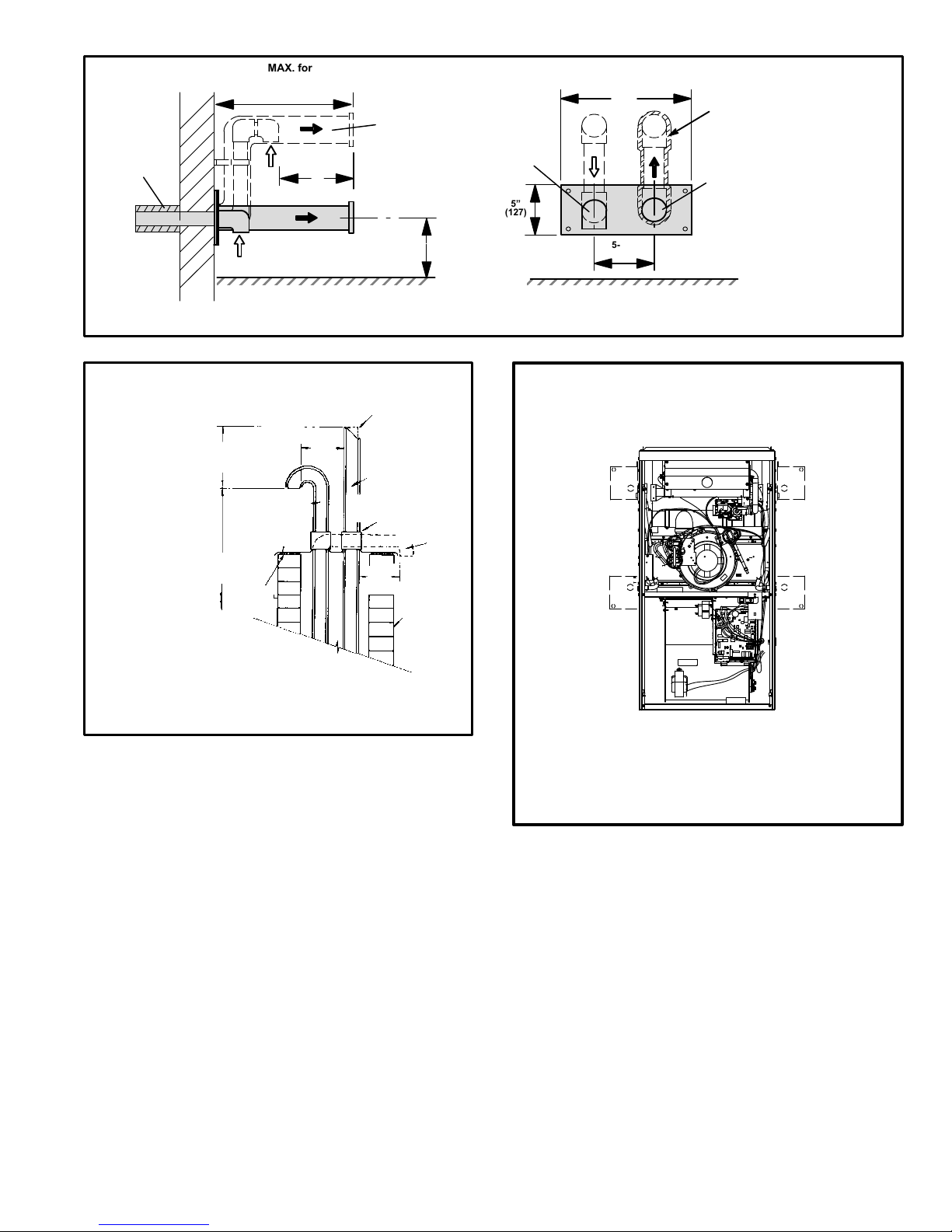
Page 45
FIGURE 31
12" MIN.
(305)
Above Grade
COVER EXHAUST
VENT WITH
1/2" (13)
FOAM
INSULATION
Front View
Side View
DIRECT VENT TERMINATION
WALL TERMINATION KIT (22G44, 44J40, 30G28 or 81J20) EXTENDED VENT FOR GRADE CLEARANCE
Inches (mm)
5"
(127)
5-1/2"
(140)
EXHAUST
AIR
GRADE
12"
(305)
8" (203)
Minimum
12" (305)
Minimum
ABOVE GRADE
EXHAUST
AIR
GRADE
12" (305) MAX. for 2" (51)
20" (508) MAX. for 3" (76)
(unless supported)
INTAKE
AIR
INTAKE
AIR
G71MPP DIRECT VENT APPLICATION
USING EXISTING CHIMNEY
NOTE − Do not discharge exhaust gases directly into any chimney or vent stack. If vertical discharge through an existing unused chimney or stack is required, insert piping
inside chimney until the pipe open end is above top of chimney and terminate as illustrated. In any exterior portion of chimney, the exhaust vent must be insulated.
FIGURE 32
8" − 12"
(203mm − 305mm)
3" − 8"
(76mm−
203mm)
3" − 8"
(76mm−
203mm)
STRAIGHT−CUT OR
ANGLE−CUT IN DIRECTION
OF ROOF SLOPE *
EXHAUST VENT
1/2" (13mm)
WEATHERPROOF
INSULATION
SHOULDER OF FITTINGS
PROVIDE SUPPORT
OF PIPE ON TOP PLATE
ALTERNATE
INTAKE PIPE
INTAKE PIPE
INSULATION (optional)
EXTERIOR
PORTION OF
CHIMNEY
INSULATE
TO FORM
SEAL
SHEET
METAL TOP
PLATE
MINIMUM 12"
(305mm) ABOVE
ROOF
*SIZE TERMINATION
PIPE PER TABLE 37.
Condensate Piping
This unit is designed for either right- or left-side exit of condensate piping in either upflow or downflow applications;
however, it must be installed on the same side of the unit as
the exhaust piping. In horizontal applications, the condensate trap should extend below the unit. A 5−1/2" service
clearance is required for the condensate trap. Refer to figure 33 for condensate trap locations.
NOTE − If necessary the condensate trap may be
installed in an alternate location in upflow applications
using kit number 76M20.
FIGURE 33
CONDENSATE TRAP LOCATIONS
(Unit shown in upflow position)
Horizontal
left and
optional
downflow
Horizontal
right and
optional
downflow
Optional
upflow
Optional
upflow
NOTE − In upflow applications where side return
air filter is installed on same side as the condensate trap, filter rack must be installed beyond
condensate trap to avoid interference.
Page 46

Page 46
1 − Determine which side condensate piping will exit the
unit. Remove plugs from the condensate collar at the
appropriate location on the side of the unit.
NOTE − The condensate trap is factory−shipped with
two rubber O−rings and two rubber clean−out caps
installed. Check to make sure that these items are in
place before installing the trap assembly.
2 − Install condensate trap onto the condensate collar.
Use provided HI/LO screws to secure two upper
flanges of the trap to the collar. Use provided sheet
metal screw to secure bottom trap flange to side of
unit. See figure 34.
NOTE − In upflow and downflow applications, condensate trap must be installed on the same side as
exhaust piping.
CAUTION
DO NOT use a power driver to tighten screws which
secure condensate trap to cabinet. Screws should
be hand−tightened using a screw driver to avoid the
possibility of damage to the trap assembly.
3 − The grey−colored condensate trap (101661−01) pro-
vided with the unit is manufactured using ABS material. This is the only trap that is to be used with this unit.
Use ABS to PVC transition solvent cement to glue a
field−provided PVC coupling or PVC pipe to the trap.
Install a tee and vent pipe near the trap.
NOTE − The condensate trap drain stubs (both sides)
have an outer diameter which will accept a standard
3/4" PVC coupling. The inner diameter of each stub
will accept standard 1/2" diameter PVC pipe.
NOTE − Vinyl tubing may be used for condensate
drain. Tubing must be 1−1/4" OD X 1" ID and should be
attached to the drain stubs on the trap using a hose
clamp.
4 − Glue the field−provided drain line to the tee. Route the
drain line to an open drain. As an alternate, clear vinyl
tubing may be used to drain condensate away from
the trap. Secure the vinyl tubing to the drain stubs on
the trap using a hose clamp. Do not overtighten the
hose clamp.
Condensate line must be sloped downward away from
condensate trap to drain. If drain level is above condensate trap, condensate pump must be used. Condensate drain line should be routed within the conditioned space to avoid freezing of condensate and
blockage of drain line. If this is not possible, a heat
cable kit may be used on the condensate trap and line.
Heating cable kit is available from Lennox in various
lengths; 6 ft. (1.8m) − kit no. 26K68; 24 ft. (7.3m) − kit
no. 26K69; and 50 ft. (15.2m) − kit no. 26K70.
CAUTION
Do not use copper tubing or existing copper
condensate lines for drain line.
5 − If unit will be started immediately upon completion of
installation, prime trap per procedure outlined in Unit
Start−Up section.
6 − Glue the provided cap onto the unused condensate
drain line stub.
CONDENSATE ASSEMBLY
FIGURE 34
COUPLING
CAP
CONDENSATE TRAP
(grey)
NIPPLE
NIPPLE
TEE
VENT
CLEAN−OUT ACCESS
(both sides)
HI/LO SCREWS
(DO NOT use power
driver. Hand−tighten
using screw driver.)
SCREW
O−RINGS
Page 47

Page 47
III−START-UP
A−Preliminary and Seasonal Checks
1 − Inspect electrical wiring, both field and factory installed
for loose connections. Tighten as required.
2 − Check voltage at disconnect switch. Voltage must be
within range listed on the nameplate. If not, consult the
power company and have voltage condition corrected
before starting unit.
B−Heating Start-Up
FOR YOUR SAFETY READ BEFORE OPERATING
WARNING
Do not use this furnace if any part has been underwater. A flood−damaged furnace is extremely dangerous. Attempts to use the furnace can result in
fire or explosion. Immediately call a qualified service technician to inspect the furnace and to replace
all gas controls, control system parts, and electrical
parts that have been wet or to replace the furnace,
if deemed necessary.
WARNING
Danger of explosion. Can cause injury
or product or property damage. Should
the gas supply fail to shut off or if
overheating occurs, shut off the gas
valve to the furnace before shutting off
the electrical supply.
CAUTION
Before attempting to perform any service or maintenance, turn the electrical power to unit OFF at disconnect switch.
Priming Condensate Trap
The condensate trap should be primed with water prior to
start−up to ensure proper condensate drainage. Either
pour 10 fl. oz. (300 ml) of water into the trap, or follow
these steps to prime the trap:
1 − Follow the lighting instructions to place the unit into op-
eration.
2 − Set the thermostat to initiate a heating demand.
3 − Allow the burners to fire for approximately 3 minutes.
4 − Adjust the thermostat to deactivate the heating de-
mand.
5 − Wait for the combustion air inducer to stop. Set the
thermostat to initiate a heating demand and again allow the burners to fire for approximately 3 minutes.
6 − Adjust the thermostat to deactivate the heating de-
mand and again wait for the combustion air inducer to
stop. At this point, the trap should be primed with sufficient water to ensure proper condensate drain operation.
BEFORE BEFORE PLACING THE UNIT INTO OPERATION, the unit, smell all around the furnace area for gas.
Be sure to smell next to the floor because some gas is
heavier than air and will settle on the floor.
The gas valve on the G71MPP is equipped with a gas
control switch. Use only your hand to move the control
switch. Never use tools. If the switch will not move by
hand, do not try to repair it. Call a licensed professional
service technician (or equivalent). Force or attempted repair may result in a fire or explosion.
Placing the furnace into operation:
G71MPP units are equipped with an automatic ignition
system. Do not
attempt to manually light burners on this
furnace. Each time the thermostat calls for heat, the
burners will automatically light. The ignitor does not get
hot when there is no call for heat on units with this ignition
system.
WARNING
If you do not follow these instructions exactly, a fire
or explosion may result causing property damage,
personal injury or death.
Gas Valve Operation (Figure 35)
1 − STOP! Read the safety information at the beginning of
this section.
2 − Set the thermostat to the lowest setting.
3 − Turn off all electrical power to the unit.
4 − This furnace is equipped with an ignition device which
automatically lights the burners. Do not try to light the
burners by hand.
5 − Remove the upper access panel.
6 − Move the gas valve switch to the OFF position. See
figure 35.
7 − Wait five minutes to clear out any gas. If you then smell
gas, STOP! Immediately call your gas supplier from a
neighbor’s phone. Follow the gas supplier’s instruc-
tions. If you do not smell gas go to next step.
GAS VALVE
GAS VALVE SHOWN IN OFF POSITION
INLET OUTLET
NEGATIVE AIR
PRESSURE PORT
POSITIVE AIR
PRESSURE PORT
SUPPLY
PRESSURE TAP
MANIFOLD
PRESSURE TAP
FIGURE 35
8 − Move gas valve switch to the ON position. See fig ure
35. Do not force.
Page 48

Page 48
9 − Replace the upper access panel.
10− Turn on all electrical power to to the unit.
11− Set the thermostat to desired setting.
NOTE − When unit is initially started, steps 1 through 11
may need to be repeated to purge air from gas line.
12− If the appliance will not operate, follow the instructions
Turning Off Gas to Unit" and call your service technician or gas supplier.
Turning Off Gas to Unit
1 − Set the thermostat to the lowest setting.
2 − Turn off all electrical power to the unit if service is to be
performed.
3 − Remove the upper access panel.
4 − Move the gas valve switch to the OFF position.
5 − Replace the upper access panel.
C−Safety or Emergency Shutdown
Turn off unit power. Close manual and main gas valves.
D−Extended Period Shutdown
Turn off thermostat or set to UNOCCUPIED" mode. Close
all gas valves (both internal and external to unit) to guarantee no gas leak into combustion chamber. Turn off power to
unit. All access panels and covers must be in place and secured.
IV−HEATING SYSTEM SERVICE CHECKS
A−C.S.A. Certification
All units are C.S.A. (formally A.G.A. and C.G.A. combined)
design certified without modifications. Refer to the
G71MPP Installation Instruction.
B−Gas Piping
CAUTION
If a flexible gas connector is required or allowed by
the authority that has jurisdiction, black iron pipe
shall be installed at the gas valve and extend outside
the furnace cabinet.
WARNING
Do not exceed 600 in−lbs (50 ft−lbs) torque when attaching the gas piping to the gas valve.
Gas supply piping should not allow more than 0.5"W.C. drop
in pressure between gas meter and unit. Supply gas pipe
must not be smaller than unit gas connection.
Compounds used on gas piping threaded joints should be
resistant to action of liquefied petroleum gases.
C−Testing Gas Piping
IMPORTANT
In case emergency shutdown is required, turn off
the main shut-off valve and disconnect the main
power to unit. These controls should be properly
labeled by the installer.
When pressure testing gas lines, the gas valve must be disconnected and isolated. Gas valves can be damaged if
subjected to more than 0.5psig (14" W.C.). See figure 36.
FIGURE 36
MANUAL MAIN SHUT−OFF VALVE
GAS VALVE
CAP
GAS PIPING TEST PROCEDURE
When checking piping connections for gas leaks, use preferred means. Kitchen detergents can cause harmful corrosion on various metals used in gas piping. Use of a specialty
Gas Leak Detector is strongly recommended. It is available
through Lennox under part number 31B2001. See Corp.
8411−L10, for further details.
Do not use matches, candles, flame or any other source of
ignition to check for gas leaks.
D−Testing Gas Supply Pressure
When testing supply gas pressure, connect test gauge to
supply pressure tap on the gas valve. See figure 35. Check
gas line pressure with unit firing at maximum rate. Low
pressure may result in erratic operation or underfire. High
pressure can result in permanent damage to gas valve or
overfire. See table 38 for operating pressure at unit gas
connection (line).
On multiple unit installations, each unit should be checked
separately, with and without units operating. Supply pressure must fall within range listed in table 38.
TABLE 38
All G71MPP Units
Natural LP
Line Pressure WC" 4.5 − 10.5 11.0 − 13.0
Page 49

Page 49
E−Check Manifold Pressure
To correctly measure manifold prressure, the differential
pressure between the positive gas manifold and the negative burner box must be considered. Use pressure test
adapter kit (available as Lennox part 10L34) to assist in
measurement.
1 − Connect test gauge +" connection to manifold pres
sure tap on the gas vavle.
2 − Tee into the gas valve regulator vent hose and connect test gauge −" connection.
3 − Start unit on low heat (40%) rate) and allow 5 minutes for unit to reach steady state.
4 − While waiting for the unit to stabilize, notice the
flame. Flame should be stable and should not lift from
burnere. Natural gas should burn blue.
5 − After allowing unit to stablize for 5 minutes, record
manifold pressure and compare to value given in table
42.
6 − Repeat stpes 3, 4 and 5 on high fire.
CAUTION
Do not attempt to make adjustments to the gas valve.
F− Proper Gas Flow (Approximate)
1 − Operate unit at least 15 minutes before checking gas
flow. Determine the time in seconds for one revolutions of gas through the meter. A portable LP gas meter (17Y44) is available for LP applications.
2 − Compare the number of seconds and the gas meter
size in table 39 to determine the gas flow rate. Multiply
the gas flow rate by the heating value to determine the
unit input rate. If manifold pressure is correct and the
unit input rate is incorrect, check gas orifices for proper
size and restriction.
3 − Remove temporary gas meter if installed.
NOTE − To obtain accurate reading, shut off all other gas
appliances connected to meter.
TABLE 39
Gas Flow Rate (Ft.
3
/Hr.)
Seconds for 1
Revolution
Gas Meter Size
1/2 cu ft Dial 1 cu ft Dial
10 180 360
12 150 300
14 129 257
16 113 225
18 100 200
20 90 180
22 82 164
24 75 150
26 69 138
28 64 129
30 60 120
32 56 11 3
34 53 106
36 50 100
38 47 95
40 45 90
42 43 86
44 41 82
46 39 78
48 38 75
50 36 72
52 35 69
54 33 67
56 32 64
58 31 62
60 30 60
G− Proper Combustion
Furnace should operate minimum 15 minutes with correct
manifold pressure and gas flow rate before checking combustion. Take combustion sample beyond the flue outlet
and compare to the tables below. The maximum carbon
monoxide reading should not exceed 100 ppm.
TABLE 40
High Fire
Unit
CO2%
For Nat
CO2%
For L.P.
G71MPP−36B−070 6.8 − 7.8 8.5 − 9.5
G71MPP−36C−090 7.2 − 8.2 8.5 − 9.5
G71MPP−60C−090 7.2 − 8.2 7.2 − 8.2
G71MPP−60C−110 7.6 − 8.6 7.6 − 8.6
G71MPP−60D−135 7.5 − 8.5 7.5 − 8.5
TABLE 41
Low Fire
Unit CO2%
For Nat
CO2%
For L.P.
G71MPP−36B−070 5.0 − 6.0 5.8 − 6.8
G71MPP−36C−090 4.9 − 5.9 5.7 − 6.7
G71MPP−60C−090 4.9 − 5.9 5.7 − 6.7
G71MPP−60C−110 5.0 − 6.0 6.2 − 7.2
G71MPP−60D−135 5.0 − 6.0 5.7 − 6.7
Page 50

Page 50
H− High Altitude
NOTE − In Canada, certification for installations at elevations over 4500 feet (1372 m) is the jurisdiction of local authorities.
G71MPP units require no manifold pressure adjustments
for operation at altitudes up to 10,000 feet (3048m) above
sea level. Units installed at altitude of 7,501 to 10,000 feet
(2287 to 3048m) require a pressure switch change per
table 42. Table 42 lists conversion kit requirements, pressure switch requirements and manifold pressures at all altitudes.
NOTE − The values given in table are measurements only.
The gas valve should not be adjusted.
The combustion air pressure switch is factory−set and requires no adjustment.
NOTE − A natural to L.P. propane gas changeover kit is necessary to convert this unit. Refer to the changeover kit
installation instruction for the conversion procedure.
TABLE 42
Conversion Kit Requirements and Manifold Test Pressures
Model
Input
Size
LP/Propane
Kit
High Altitude Pressure
Switch Kit
Manifold Pressure at All Altitudes (in. w.g.)
0 − 10,000
(0 − 3048 m)
0 − 7,500
(0 − 2286 m)
7,501 − 10,000
(2287 −
3048m)
Low Fire
(40% rate)
High Fire
(100% rate)
Natural Gas LP/Propane Natural Gas LP/Propane
−070
33W41 Not required
33W27
0.7 2.0 3.5 10.0
−090 40W05
−110 40W06
−135 40W07
NOTE − Pressure switch is factory set. No adjustment necessary. All models use the factory installed pressure switch from 0−7,500 feet (0− 2286m).
NOTE − See previous page for manifold pressure measurement procedure.
Page 51

Page 51
V−TYPICAL OPERATING CHARACTERISTICS
A−Blower Operation and Adjustment
1 − Blower operation is dependent on thermostat control
system.
2 − Generally, blower operation is set at thermostat sub-
base fan switch. With fan switch in ON position, blower
operates continuously. With fan switch in AUTO position,
blower cycles with demand or runs continuously while
heating or cooling circuit cycles.
3 − Depending on the type of indoor thermostat, blower
and entire unit will be off when the system switch is in
OFF position.
B−Temperature Rise
Temperature rise for G71MPP units depends on unit input,
blower speed, blower horsepower and static pressure as
marked on the unit rating plate. The blower speed must be
set for unit operation within the range of TEMP. RISE °F"
listed on the unit rating plate.
To Measure Temperature Rise:
1 − Place plenum thermometers in the supply and return air
plenums. Locate supply air thermometer in the first horizontal run of the plenum where it will not pick up radiant
heat from the heat exchanger.
2 − Set thermostat for heat call. Unit must operate on sec-
ond−stage heat. If using a single−stage thermostat fur-
nace must fire at least 10 minutes before switching to
second−stage heat.
3 − After plenum thermometers have reached their high-
est and steadiest readings, subtract the two readings.
The difference should be in the range listed on the unit
rating plate. If the temperature is too low, decrease
blower speed. If temperature is too high, first check the
firing rate. Provided the firing rate is acceptable, in-
crease blower speed to reduce temperature.
C−External Static Pressure
1 − Tap locations shown in figure 37.
2 − Punch a 1/4" diameter hole
in supply and return air ple-
nums. Insert manometer
hose flush with inside edge
of hole or insulation. Seal
around the hose with perma-
gum. Connect the zero end
of the manometer to the dis-
charge (supply) side of the system. On ducted sys-
tems, connect the other end of manometer to the return
duct as above. For systems with non−ducted returns,
leave the other end of the manometer open to the at-
mosphere.
3 − With only the blower motor running and the evaporator
coil dry, observe the manometer reading. Adjust blow-
er motor speed to deliver the air desired according to
the job requirements.
4 − External static pressure drop must not be more than
0.8" W.C.
5 − Seal around the hole when the check is complete.
FIGURE 37
STATIC PRESSURE TEST
Page 52
Page 52
VI−MAINTENANCE
WARNING
ELECTRICAL SHOCK, FIRE,
OR EXPLOSION HAZARD.
Failure to follow safety warnings exactly could result
in dangerous operation, serious injury, death or
property damage.
Improper servicing could result in dangerous operation, serious injury, death, or property damage.
Before servicing, disconnect all electrical power to
furnace.
When servicing controls, label all wires prior to disconnecting. Take care to reconnect wires correctly.
Verify proper operation after servicing.
At the beginning of each heating season, system should be
checked as follows by a qualified service technician:
Blower
Check the blower wheel for debris and clean if necessary.
The blower motors are prelubricated for extended bearing
life. No further lubrication is needed.
WARNING
The blower access panel must be securely in place
when the blower and burners are operating. Gas
fumes, which could contain carbon monoxide, can
be drawn into living space resulting in personal injury or death.
Filters
All G71MPP filters are installed external to the unit. Filters
should be inspected monthly. Clean or replace the filters
when necessary to ensure proper furnace operation.
Table 43 lists recommended filter sizes.
TABLE 43
Furnace
Cabinet Size
Filter Size
Side Return Bottom Return
B Cabinet (17−1/2") 16 X 25 X 1 (1) 16 X 25 X 1 (1)
C Cabinet (21") 16 X 25 X 1 (1) 20 X 25 X 1 (1)
D Cabinet (24−1/2") 16 X 25 X 1 (2) 24 X 25 X 1 (1)
Exhaust and air intake pipes
Check the exhaust and air intake pipes and all connections
for tightness and to make sure there is no blockage.
Electrical
1 − Check all wiring for loose connections.
2 − Check for the correct voltage at the furnace (furnace
operating).
3 − Check amp−draw on the blower motor.
Motor Nameplate__________Actual__________
Winterizing and Condensate Trap Care
1 − Turn off power to the unit.
2 − Have a shallow pan ready to empty condensate water.
3 − Remove the drain plug from the condensate trap and
empty water. Inspect the trap then reinstall the drain
plug and refill trap with water.
Cleaning Heat Exchanger
If cleaning the heat exchanger becomes necessary, follow
the below procedures and refer to figure 1 when disassembling unit. Use papers or protective covering in front of furnace while removing heat exchanger assembly.
1 − Turn off electrical and gas supplies to the furnace.
2 − Remove the upper and lower furnace access panels.
3 − Disconnect the 2−pin plug from the gas valve.
4 − Remove gas supply line connected to gas valve. Re-
move gas valve/manifold assembly.
5 − Remove sensor wire from sensor. Disconnect 2-pin
plug from the ignitor.
6 − Disconnect wires from flame roll−out switches.
7 − Remove burner box cover and remove four burner box
screws at the vestibule panel and remove burner box.
Set burner box assembly aside.
NOTE − G71MPP−135 units are secured to the vestibule panel by two additional screws. These screws
must be removed for servicing; however it is not necessary to replace the screws.
NOTE − If necessary, clean burners at this time. Follow
procedures outlined in Burner Cleaning section.
8 − Loosen three clamps and remove flexible exhaust tee.
9 − Remove 3/8 inch rubber cap from condensate drain
plug and drain. Replace cap after draining.
10 − Disconnect condensate drain line from the conden-
sate trap. Remove condensate trap (it may be necessary to cut drain pipe). Remove screws that secure
condensate collars to either side of the furnace and remove collars. Remove drain tubes from cold end
header collector box.
11 − Disconnect condensate drain tubing from flue collar.
Remove screws that secure both flue collars into
place. Remove flue collars. It may be necessary to cut
the exiting exhaust pipe for removal of the fittings.
12 − Mark and disconnect all combustion air pressure tub-
ing from cold end header collector box.
13 − Mark and remove wires from pressure switches. Re-
move pressure switches. Keep tubing attached to
pressure switches.
14 − Disconnect the 4-pin plug from the combustion air in-
ducer. Disconnect the two wires to the backup secondary limit, if applicable. Remove four screws which secure combustion air inducer to collector box. Remove
combustion air inducer assembly. Remove ground
wire from vest panel.
15 − Remove electrical junction box from the side of the fur-
nace.
16 − Mark and disconnect any remaining wiring to heating
compartment components. Disengage strain relief
bushing and pull wiring and bushing through the hole in
the blower deck.
17 − Remove the primary limit from the vestibule panel.
Page 53

Page 53
18 − Remove two screws from the front cabinet flange at
the blower deck. Spread cabinet sides slightly to allow
clearance for removal of heat exchanger.
19 − Remove screws along vestibule sides and bottom
which secure vestibule panel and heat exchanger assembly to cabinet. Remove two screws from blower
rail which secure bottom heat exchanger flange. Remove heat exchanger from furnace cabinet.
20 − Back wash heat exchanger with soapy water solution
or steam. If steam is used it must be below 275°F
(135°C) .
21 − Thoroughly rinse and drain the heat exchanger. Soap
solutions can be corrosive. Take care to rinse entire
assembly.
22 − Reinstall heat exchanger into cabinet making sure that
the clamshells of the heat exchanger assembly are
resting on the support located at the rear of the cabinet. Remove the indoor blower to view this area
through the blower opening.
23 − Re-secure the supporting screws along the vestibule
sides and bottom to the cabinet.
24 − Reinstall cabinet screws on front flange at blower
deck.
25 − Reinstall the primary limit on the vestibule panel.
26 − Route heating component wiring through hole in blow-
er deck and reinsert strain relief bushing.
27 − Reinstall electrical junction box.
28 − Reinstall the combustion air inducer. Reconnect the
4−pin plug to the wire harness. Reconnect the two
wires to the backup secondary limit, if applicable.
29 − Reinstall pressure switches and reconnect pressure
switch wiring.
30 − Carefully connect combustion air pressure switch
hosing from pressure switches to proper stubs on
cold end header collector box.
31 − Reinstall condensate collars on each side of the fur-
nace. Reconnect drain tubing to collector box.
32 − Reinstall condensate trap on same side as exhaust
pipe. Reconnect condensate drain line to the conden-
sate trap.
33 − Use securing screws to reinstall flue collars to either
side of the furnace. Reconnect exhaust piping and ex-
haust drain tubing.
34 − Replace flexible exhaust tee on combustion air induc-
er and flue collars. Secure using three existing hose
clamps.
35 − Reinstall burner box assembly in vestibule area.
36 − Reconnect flame roll−out switch wires.
37 − Reconnect sensor wire and reconnect 2−pin plug from
ignitor.
38 − Secure burner box assembly to vestibule panel using
four existing screws. Make sure burners line up in
center of burner ports.
39 − Reinstall gas valve manifold assembly. Reconnect
gas supply line to gas valve.
40 − Reinstall burner box cover.
41 − Reconnect 2−pin plug to gas valve.
42 − Replace the blower compartment access panel.
43 − Refer to instruction on verifying gas and electrical con-
nections when re−establishing supplies.
44 − Follow lighting instructions to light and operate fur-
nace for 5 minutes to ensure that heat exchanger is
clean and dry and that furnace is operating properly.
45 − Replace heating compartment access panel.
Cleaning the Burner Assembly
1 − Turn off electrical and gas power supplies to furnace.
Remove upper and lower furnace access panels.
2 − Disconnect the 2−pin plug from the gas valve.
3 − Disconnect the gas supply line from the gas valve. Re-
move gas valve/manifold assembly.
4 − Mark and disconnect sensor wire from the sensor. Dis-
connect 2-pin plug from the ignitor at the burner box.
5 − Remove burner box cover and remove four screws
which secure burner box assembly to vest panel. Re-
move burner box from the unit.
NOTE − G71MPP−135 units are secured to the vesti-
bule panel by two additional screws. These screws
must be removed for servicing; however it is not nec-
essary to replace the screws.
6 − Use the soft brush attachment on a vacuum cleaner to
gently clean the face of the burners. Visually inspect
the inside of the burners and crossovers for any block-
age caused by foreign matter. Remove any blockage.
7 − Reconnect the sensor wire and reconnect the 2−pin
plug to the ignitor wiring harness.
8 − Reinstall the burner box assembly using the existing
four screws. Make sure that the burners line up in the
center of the burner ports.
9 − Reinstall the gas valve manifold assembly. Reconnect
the gas supply line to the gas valve. Reinstall the burn-
er box cover.
10 − Reconnect 2−pin plug to gas valve.
11 − Replace the blower compartment access panel.
12 − Refer to instruction on verifying gas and electrical con-
nections when re−establishing supplies.
13 − Follow lighting instructions to light and operate fur-
nace for 5 minutes to ensure that heat exchanger is
clean and dry and that furnace is operating properly.
14 − Replace heating compartment access panel.
Page 54

Page 54
VII− Wiring and Sequence of Operation
NOTE − The thermostat selection DIP switch on the control
board is factory−set in the TWO−STAGE" position.
Applications Using a Two−Stage Thermostat
A − Heating Sequence −− Control Board Thermostat
Selection DIP switch in Variable Capacity" Position
1. On a call for heat, thermostat first−stage contacts close
sending a signal to the integrated control. The integrated control runs a self-diagnostic program and
checks high temperature limit switches for normally
closed contacts and pressure switches for normally
open contacts.The combustion air inducer is energized at ignition speed, which is approximately the
same as the inducer speed at 70 percent firing rate.
2. Once the control receives a signal that the low−fire
pressure switch has closed, the combustion air inducer begins a 15−second pre−purge in ignition speed.
3. After the pre−purge is complete, a 20−second initial ignitor warm−up period begins. The combustion air inducer continues to operate at the ignition speed.
4 − After the 20−second warm−up period has ended, the gas
valve is energized and ignition occurs. At the same time,
the control module begins an indoor blower 45−second
ON−delay. When the delay ends, the indoor blower
motor is energized at a speed that matches the firing
rate. After the 10−second ignition stabilization delay
expires, the inducer speed is adjusted to the appropri-
Page 55

Page 55
ate target rate. If the furnace is operating in the initial
heating cycle after power−up, the initial firing rate will
be approximately 40 percent. The firing rate on subsequent cycles will be automatically adjusted by the integrated control based on thermostat cycles. The firing
rate will vary and will range from 40 percent to 90 percent. The furnace will continue this operation as long
as the thermostat has a first−stage heating demand.
5 − If second−stage heat is required, the thermostat sec-
ond−stage heat contacts close and send a signal to the
integrated control. The integrated control either increases the firing rate to 70 percent (if the current rate
is at or below 60 percent) or increases the firing rate
by 10 percent (if the current rate is above 60 percent).
If the call for heat continues 5 minutes beyond this
initial upstage, the rate will be increased by 10 percent
every 5 minutes until the call for heat is satisfied or the
furnace reaches 100 percent rate. As the firing rate increases, the indoor blower motor is adjusted to a
speed which is appropriate for the target rate.
6 − If second−stage heat demand is satisfied, but first
stage is still present, the furnace will continue to operate at the present firing rate until the heat cycle ends.
7 − When the demand for first− and second−stage heat is
satisfied, the gas valve is de−energized and the field−
selected indoor blower off delay begins. The combustion air inducer begins a 20−second post−purge period.
8 − When the combustion air post−purge period is com-
plete, the inducer is de−energized. The indoor blower
is de−energized at the end of the off delay.
Applications Using A Single−Stage Thermostat
B − Heating Sequence −− Control Board Thermostat
Selection DIP switch in Single−Stage" Position
1. On a call for heat, thermostat first−stage contacts close
sending a signal to the integrated control. The integrated control runs a self-diagnostic program and
checks high temperature limit switches for normally
closed contacts and pressure switches for normally
open contacts.The combustion air inducer is energized at the ignition speed, which is approximately the
same as the inducer speed at 70 percent firing rate.
2. Once the control receives a signal that the low−fire
pressure switch has closed, the combustion air inducer begins a 15−second pre−purge at the ignition speed.
3. After the pre−purge is complete, a 20−second initial ignitor warm−up period begins. The combustion air inducer continues to operate at the ignition speed.
4 − After the 20−second warm−up period has ended, the gas
valve is energized and ignition occurs, which initiates a
10−second ignition stabilization delay. At the same time,
the control module sends a signal to begin an indoor
blower 45−second ON−delay. When the delay ends,
the indoor blower motor is energized at a speed which
is appropriate for the firing rate. After the 10−second
ignition stabilization delay expires, the inducer speed
is adjusted to 40 percent speed.The integrated control
also initiates a second−stage on delay (factory−set at
7 minutes; adjustable to 12 minutes).
5 − If the heating demand continues beyond the second−
stage on delay, the integrated control energizes the
combustion air inducer at 70 percent speed. The indoor blower motor is adjusted to a speed which
matches the target rate. A fixed, 10−minute third−stage
on delay is initiated.
6 − If the heating demand continues beyond the third−
stage on delay, the integrated control energizes the inducer at high speed. The indoor blower motor is adjusted to a speed which is appropriate for the target
rate.
7 −When the thermostat heating demand is satisfied, the
gas valve is de−energized and the combustion air inducer begins a 20−second post−purge. The field−selected indoor blower off delay begins.
8 − When the combustion air post−purge period is com-
plete, the inducer is de−energized. The indoor blower
is de−energized at the end of the off delay.
Applications Using a Two−Stage Thermostat
C − Heating Sequence −− Control Board Thermostat
Selection DIP switch in Two−Stage" Position (Factory
Setting)
1. On a call for heat, thermostat first−stage contacts close
sending a signal to the integrated control. The integrated control runs a self-diagnostic program and
checks high temperature limit switches for normally
closed contacts and pressure switches for normally
open contacts.The combustion air inducer is energized at ignition speed, which is approximately the
same as the inducer speed at 70 percent firing rate.
2. Once the control receives a signal that the low−fire
pressure switch has closed, the combustion air inducer begins a 15−second pre−purge at the ignition speed.
3. After the pre−purge is complete, a 20−second initial ignitor warm−up period begins. The combustion air inducer continues to operate at the ignition speed.
4 − After the 20−second warm−up period has ended, the gas
valve is energized and ignition occurs. At the same time,
the control module sends a signal to begin an indoor
blower 45−second ON−delay. When the delay ends,
the indoor blower motor is energized at a speed that
matches the firing rate. After the 10−second ignition
stabilization delay expires, the inducer speed is adjusted to the appropriate target rate. The inducer will
remain at the 70 percent speed as long as the thermostat has a first−stage heating demand.
5 − If second−stage heat is required, the thermostat sec-
ond−stage heat contacts close and send a signal to the
integrated control. The integrated control initiates a
30−second second−stage recognition delay.
6 − At the end of the recognition delay and on all subse-
quent calls for heat in the same heating cycle, the integrated control energizes the combustion air inducer at
high speed. The control also checks the high−fire pressure switch to make sure it is closed. As the inducer
speed is increased to high, the indoor blower motor is
adjusted to a speed which is appropriate for the target
rate.
7 − When the demand for high−fire (second stage) heat is
satisfied, the gas valve is de−energized and the field−
selected indoor blower off delay begins. The combustion air inducer begins a 20−second post−purge period.
8 − When the combustion air post−purge period is com-
plete, the inducer is de−energized. The indoor blower
is de−energized at the end of the off delay.
Page 56
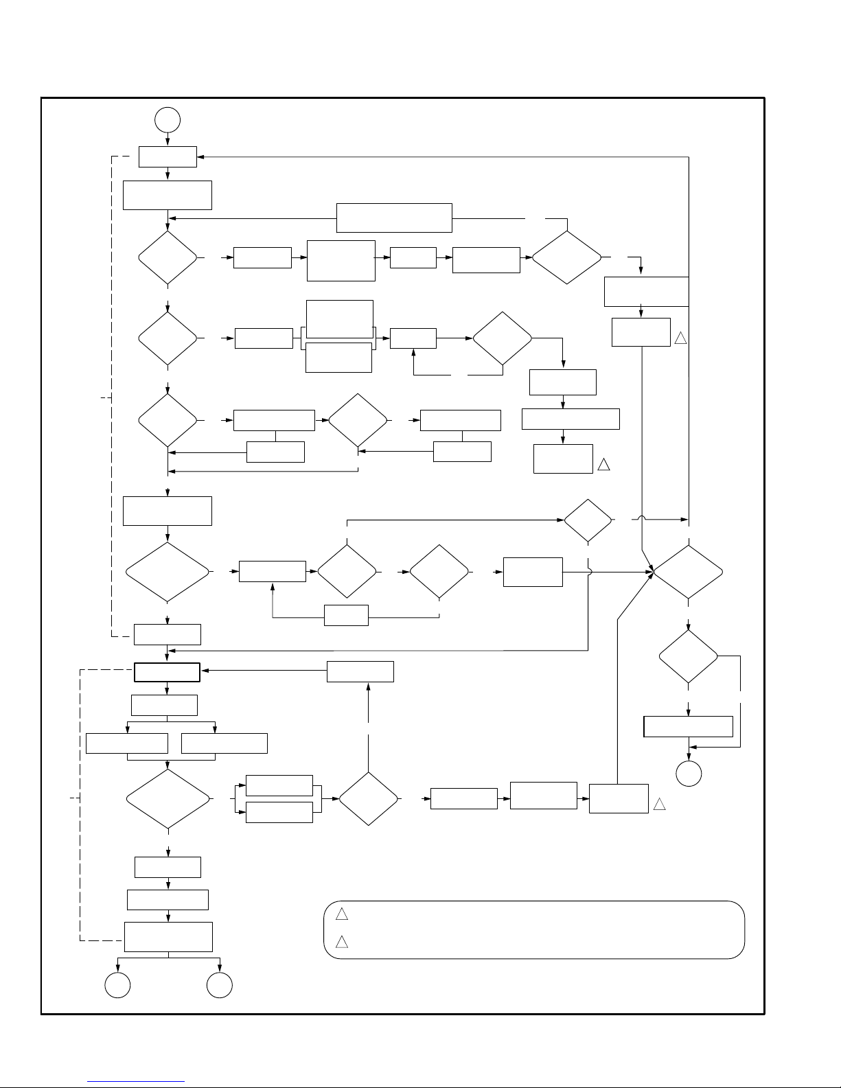
Page 56
A − Sequence of Operation and Troubleshooting Flow Chart
IGNITION AND CALL FOR LOW FIRE WITH TWO−STAGE THERMOSTAT
Call For 2nd Stage Heat Call For Heat Satisfied
Limit
Switch
Closed?
Limit
Closes Within 3
Minutes?
NO
Soft Lockout:
Error Code
Flashes
flashes
YES
Rollout
Circuit
Closed?
Low
Pressure
Switch
Open?
Low
Pressure Switch
Closed Within 150
Seconds?
High
Pressure
Switch
Open?
YES
NO
NO
NO
NO
YES
NO
De−Energize
Gas Valve
De−Energize
Gas Valve
Error Code
Flashes
Error Code
Flashes
Rollout
Circuit
Closes?
Hard Lockout:
Error Code
Flashes
Error Code Flashes
After 5 Seconds
Error Code Flashes
After 5 Seconds
L
I
G
H
T
O
F
F
Safety
Check
After
(Low Heat Speed)
Verify There
Is No Main Burner
Flame
YES
YES
Low Pressure
Switch Opens
High Pressure
Switch Opens
YES
NO
Pressure Switch
Calibration
Pre−Purge
15 Seconds
YES
Gas Valve
Energized
Flame
Sensed Within
4 seconds?
Gas Valve
De−energized
Interpurge
(15 Seconds)
5th
Unsuccessful
Trial?
Wait For Ignition
Stabilization Delay
Post−Purge
(20Seconds)
Soft Lockout:
Error Code
Flashes
YES
NO
NO
YES
Call For
Heat
Ends?
NO
YES
YES NO
C
A
L
L
F
O
R
1
S
T
S
T
A
G
E
H
E
A
T
3A2
1
1
OR
Call
For
Heat?
NO
4
Calibrations
Attempted?
Calibration
Successful?
Wait
5 minutes
NO
NO
Soft Lockout:
Error Code
Flashes
YES
YES
YES
2
1
1
2
Set Target Firing Rate
Based on Thermostat
Signals Present
SOF T LOCKOU T IS RESE TAUTOMATICALLY AFTER ONE HOUR WITH A CALL FOR HE AT ACTIVE,
OR B Y CYCLING THE CAL L FOR HE AT, OR B Y CYCLING POWER TO THE CONTROL.
HARD LOCKOU T IS RESE T BY CYCLING POWER TO THE CONTROL.
1
2
Indoor blower OFF
Combustion Air
Inducer On
(100% rate speed)
Indoor Blower
ON (100%)
Heat OFF Delay
Indoor Blower OFF
After Heat OFF Delay
(High Heat Speed)
Combustion
Air Inducer
On (100% rate
speed)
Indoor Blower
ON (70%)
Combustion Air
Inducer OFF
After Post−Purge
Indoor Blower OFF After
Heat OFF Delay
Combustion Air Inducer
ON at 70% Rate Speed
Ignitor ON
20 Seconds
Indoor
Blower
ON?
Indoor blower OFF
After Heat OFF Delay
Indoor Blower Delay
Timer Started
Ignition Trial Begins
(Ignitor ON)
Ignitor OFF
Ignitor OFF
Combustion Air
Inducer OFF
Page 57

Page 57
CALL FOR HIGH FIRE WITH TWO−STAGE THERMOSTAT
1st Call
for High
Fire?
Wait for Call for Heat Satisfied
2 Stage
Thermostat
2nd Stage
Recognition Delay
(30 Seconds)
YES
High
Pressure Switch
Closes Within
10 Seconds?
NO
Error Code
Flashes
NO
YES
Wait 5
Minutes
3A
2
1
2
1
System will always light at 70% even if 2nd stage call for heat is in place
If the high pressure switch does not close within 5 attempts, the system
will operate at low fire for the remainder of the call for heat at request
Combustion Air Inducer ON
(100% Rate Speed)
Increase Combustion
Air Inducer Speed
if Not at 100%
Rate Speed
Adjust Indoor
Blower to
Appropiate speed
Page 58

Page 58
CALL FOR HEAT SATISFIED
1st Stage Heat
2nd Stage Heat
2nd Stage
Call for Heat
satisfied?
NO
1st Stage
Call for Heat
satisfied?
Gas valve
De−Energized
YES
NO
Wait for Call −
2−StageThermostat
Wait for Call −
Single StageThermostat
1 4
3A 3B
YES
OR
Combustion Air Inducer
switched to 70% rate speed
Adjust Indoor Blower
to appropiate speed
Combustion Air Inducer OFF
after 20−Second Post Purge
Indoor Blower OFF
after OFF Delay
RUN MODE (2 STAGE THEREMOSTAT)
1ST OR 2ND STAGE CALL FOR HEAT ALL
INPUTS MONITORED (LIMIT, PRESSURE,
CALL FOR HEAT / COOL, FLAME LEVEL)
RUN MODE (SINGLE STAGE THERMOSTAT)
ALL INPUTS MONITORED (LIMIT, PRESSURE,
CALL FOR HEAT / COOL, FLAME LEVEL)
Page 59

Page 59
IGNITION AND CALL FOR LOW FIRE WITH SINGLE−STAGE THERMOSTAT
Call For Heat Satisfied
Limit
Switch
Closed?
Limit
Closes Within 3
Minutes?
NO
Soft Lockout:
Error Code
Flashes
flashes
YES
Rollout
Circuit
Closed?
Low
Pressure
Switch
Open?
Low
Pressure Switch
Closed Within 150
Seconds?
High
Pressure
Switch
Open?
YES
NO
NO
NO
NO
YES
NO
De−Energize
Gas Valve
De−Energize
Gas Valve
Error Code
Flashes
Error Code
Flashes
Rollout
Circuit
Closes?
Hard Lockout:
Error Code
Flashes
Error Code Flashes
After 5 Seconds
Error Code Flashes
After 5 Seconds
L
I
G
H
T
O
F
F
Safety
Check
Verify There
Is No Main Burner
Flame
YES
YES
Low Pressure
Switch Opens
High Pressure
Switch Opens
YES
NO
Pre−Purge
15 Seconds
YES
Gas Valve
Energized
Ignition Trial Begins
Flame
Sensed Within
4 seconds?
Gas Valve
De−energized
Interpurge
(15 Seconds)
5th
Unsuccessful
Trial?
Wait For Ignition
Stabilization Delay
Post−Purge
(20 Seconds)
Soft Lockout:
Error Code
Flashes
YES
NO
NO
YES
Call For
Heat
Ends?
NO
YES
YES NO
C
A
L
L
F
O
R
H
E
A
T
3B
1
4
Move to Mid Firing Rate
and High Firing Rate after
2nd and 3rd Stage Delays
(based on DI P Switch selections)
Pressure Switch
Calibration
Call
For
Heat?
NO
4
Calibrations
Attempted?
Calibration
Successful?
Wait
5 minutes
NO
NO
Soft Lockout:
Error Code
Flashes
YES
YES
YES
SOFT LOCKOUT IS RESET AUTOMATICALLY AFTER ONE HOUR WITH A CALL FOR HEAT ACTIVE,
OR BY CYCLINGTHE CALL FOR HEAT, OR BY CYCLING POWER TO THE CONTROL.
HARD LOCKOUT IS RESE T BY CYCLING POWER TO THE CONTROL.
1
2
1
2
1
Set to
Low Firing Rate
Indoor Blower OFF After
Heat OFF Delay
(Low Heat Speed)
Combustion Air
Inducer ON
(100%)
Indoor Blower
ON
(100% Speed)
Indoor Blower OFF
After Heat OFF Delay
(High Heat Speed)
Combustion Air
Inducer ON
(100%)
Indoor Blower
ON
(70%)
Combustion Air Inducer
OFF After Post−Purge
Indoor Blower OFF After
Heat OFF Delay
Combustion Air Inducer ON at
Ignition at 70% rate speed
Indoor
Blower On?
Indoor Blower OFF
After Heat OFF Delay
Ignitor ON
20 Seconds
Ignitor ON
Indoor Blower On
Delay Timer Started
Ignitor OFF
Combustion Air
Inducer OFF
Ignitor OFF
Page 60
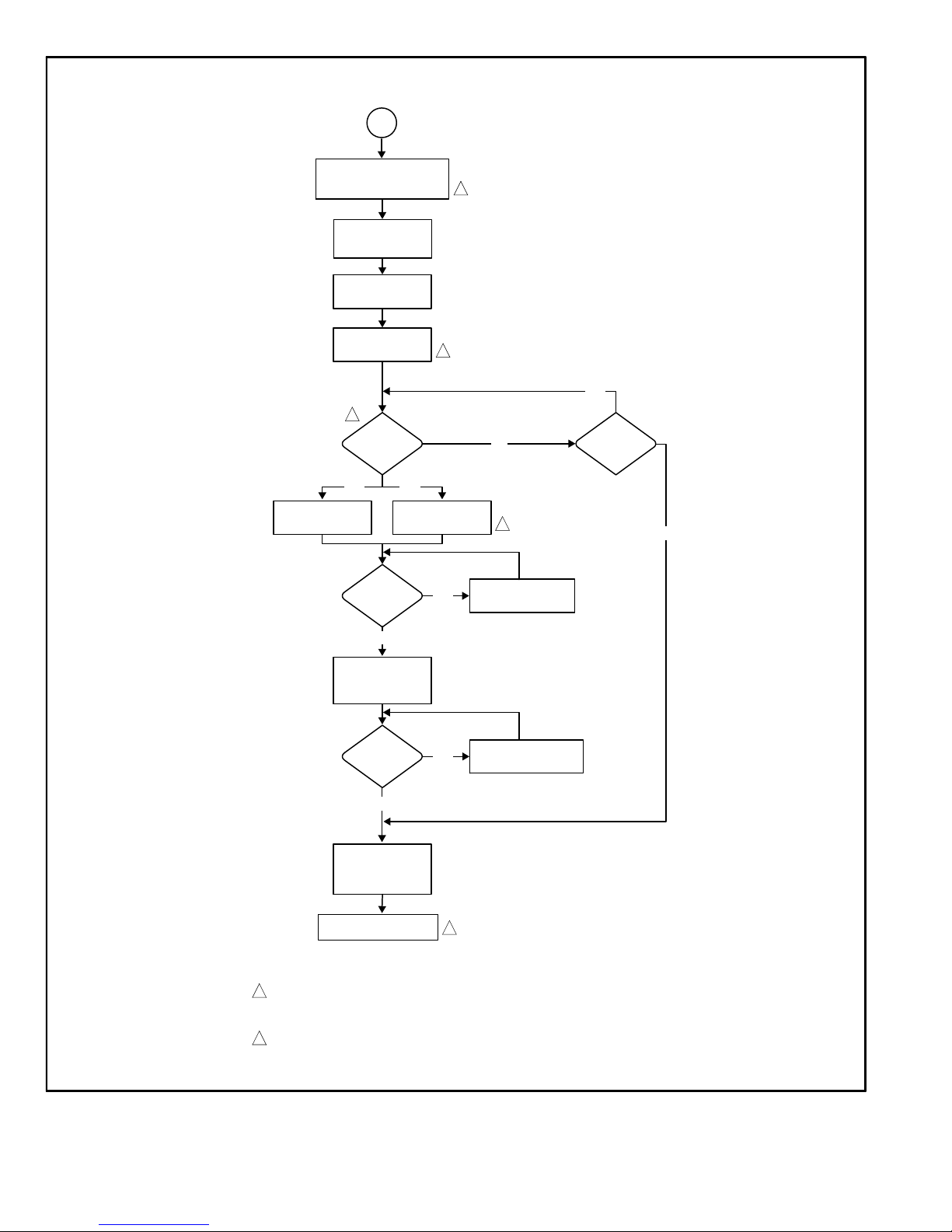
Page 60
CALL FOR COOLING
1st Stage Cooling
Request Received
Energize 1st Stage
Cooling Contactor
(Compressor & Fan)
2nd Stage
Cooling
Request?
YES
2nd Stage
Cooling Request
Still Active?
De−Energize 1st
Stage Cooling
Contactor
(Compressor & Fan)
YES
1st Stage
Cooling Request
Still Active?
NO
YES
YES
Energize 2nd Stage
Cooling Contactor
(Compressor & Fan)
1st Stage
Cooling Request
Still Active?
De−Energize 2nd
Stage Cooling
Contactor
(Compressor & Fan)
Energize and
Low Cooling mode
(High Cooling mode)
(High Cooling mode)
Per Ramping Profile
NO
NO
YES
NO
5
1
2
1
2
2
2
1
Indoor Blower On
After 2−second delay
Energize Indoor Blower
(Per Ramping Profile)
Energize Indoor Blower
Maintain Indoor Blower
Maintain Indoor Blower at
De−Energize Indoor Blower
2nd stage cooling operation requires a 2−stage thermostat, a 2−stage cooling system and jumpers
W915 must be be cut. The control will not respond to a 2nd stage cooling request unless a 1st stage
cooling request is active
Indoor blower cooling mode and high cooling mode have a specific ON, OFF and speed ramping
profiles. The specific profile is selected using the DIP switches on the control.
Page 61

Page 61
CONTINUOUS LOW SPEED INDOOR BLOWER SEQUENCE OF OPERATION
(Speed Determined by
Dip Switch settings)
De−Energize
Ramping Profile
NO
Request
for Heat
Received?
Request
for Cooling
Received?
NO
YES
Call for Fan
Removed?
YES
NO
YES
Go to Call for Cooling
Go to Call for Heat − 2 Stage
Thermostat
Go to Call for Heat − Single Stage
Thermostat
6
1
4
5
1
1
Call for
Continuous Blower
Indoor Blower On
Maintain Indoor
Blower at set speed
Maintain Indoor
Blower at set speed
OR
Maintain Indoor
Blower at set speed
Indoor Blower Per
Indoor blower low cooling mode and high cooling mode, have specific ON − OFF and speed ramping
profiles. The specific profile is selected using the dip switches on the control.
Page 62

Page 62
VIII− Field Wiring
TABLE 44
Field Wiring Applications
Thermostat
DIP Switch Settings and On−Board Links (figure 4)
Wiring Connections
DIP Switch 1
W915
(Y1 to Y2)
Two−Stage
Cooling
W914
(DS to R)
Dehumidifi-
cation or
Harmony
IIIt
W951
(O to R)
Heat Pumps
1Heat / 1 Cool
NOTE − Use DIP
switch 3 to set
second−stage
heat ON delay.
OFF−7 minutes.
ON−12 minutes.
ON Intact Intact Intact
S1
T’STAT
CONTROL
TERM. STRIP
OUTDOOR
UNIT
*
1 Heat / 2 Cool
NOTE − Use DIP
switch 3 to set
second−stage
heat ON delay.
OFF−7 minutes.
ON−12 minutes.
ON Cut Intact Intact
S1
T’STAT
CONTROL
TERM. STRIP
OUTDOOR
UNIT
*
1 Heat / 2 Cool
with t’stat with
dehumidification
mode
NOTE − Use DIP
switch 3 to set
second−stage
heat ON delay.
OFF−7 minutes.
ON−12 minutes.
ON Cut Cut Intact
S1
T’STAT
CONTROL
TERM. STRIP
OUTDOOR
UNIT
*
* R" required on some units.
Page 63

Page 63
TABLE 44
Field Wiring Applications
Thermostat
DIP Switch Settings and On−Board Links (figure 4)
Wiring Connections
DIP Switch 1
W915
(Y1 to Y2)
Two−Stage
Cooling
W914
(DS to R)
Dehumidifi-
cation or
Harmony
IIIt
W951
(O to R)
Heat Pumps
2 Heat / 2 Cool OFF Cut Intact Intact
S1
T’STAT
CONTROL
TERM. STRIP
OUTDOOR
UNIT
*
2 Heat / 2 Cool
with t’stat with
dehumidification mode
OFF Cut Cut Intact
S1
T’STAT
CONTROL
TERM. STRIP
OUTDOOR
UNIT
*
2 Heat / 1 Cool OFF Intact Intact Intact
S1
T’STAT
CONTROL
TERM. STRIP
OUTDOOR
UNIT
*
* R" required on some units.
Page 64

Page 64
TABLE 44
Field Wiring Applications (Continued)
Thermostat
DIP Switch Settings and On−Board Link (figure 4)
Wiring Connections
DIP Switch
W915
(Y1 to Y2)
Two−Stage
Cooling
W914
(DS to R)
Dehumidifi-
cation or
Harmony
IIIt
W951
(O to R)
Heat Pumps
Dual Fuel
Single Stage
Heat Pump
ComfortSense
7000 L7724U
thermostat w/
dual fuel capabilities
Capable of 2
stage gas heat
control
DIP Switch 1
OFF
Intact Intact Cut
L7724U
T’STAT
CONTROL
TERM. STRIP
HEAT PUMP
67M41*
Y
H
L
Y2
D
B
L
Y2
T
T
outdoor
sensor
Dual Fuel
Two Stage
Heat Pump
ComfortSense
7000 L7724U
thermostat w/
dual fuel capabilities
Capable of 2
stage gas heat
control
DIP Switch 1
OFF
Cut Intact Cut
CONTROL TERM.
STRIP
HEAT PUMP
out
blue
67M41*
H
L
Y2
D
B
L
Y2
T
T
outdoor
sensor
L7724U
T’STAT
* Connect W1 to W1 ONLY if using defrost tempering kit 67M41
 Loading...