

Lennox G71MPP-36B-070, G71MPP-60C-090, G71MPP-60D-135, G71MPP-36C-090, G71MPP-60C-110 Installation Instructions Manual
Page 1
E Wvm)
_ 2007 Lennox Industries Inc.
Dallas, Texas, USA
®
INSTALLATION
INSTRUCTIONS
G71MPP SERIES UNITS
RETAIN THESE INSTRUCTIONS
FOR FUTURE REFERENCE
GAS UNITS
50&334M
03/2008 J LJ _,Publications
Unit Dimensions ............................... 2
G71MPP Parts Arrangement ..................... 3
Shipping and Packing List ....................... 4
Safety Information .............................. 4
General ....................................... 6
Installation - Setting Equipment .................. 6
Filters ........................................ 12
Duct System .................................. 13
Pipe & Fittings Specifications ................... 13
Vent Pipe Sizing Worksheet .................... 14
Vent Piping Guidelines ......................... 15
Joint Cementing Procedure ..................... 16
Venting Practices ............................. 17
Gas Piping ................................... 25
Electrical ..................................... 27
Integrated Control ............................. 33
Blower Motor Performance ..................... 40
Unit Start-Up ................................. 51
Gas Pressure Measurement .................... 52 ,
High Altitude Information ....................... 53
Other Unit Adjustments ........................ 54
Heating Sequence of Operation ................. 55
Service ...................................... 57
Ignition Control Diagnostic Codes ............... 59
Troubleshooting ............................... 60
Repair Parts List .............................. 66
Start-Up & Performance Check List .............. 66
Technical
Litho U.S.A.
Do not store or use gasoline or other
flammable vapors and liquids in the
vicinity of this or any other ap-
pliance.
Installation and service must be
performed by a qualified installer,
service agency or the gas supplier.
03/08
IIIHIININIIIIIIIIIIIIIIIIIIIIIIIIIIII
AWARNING
WHAT TO DO IF YOU SMELL GAS:
• Do not try to light any appliance.
• Do not touch any electrical switch; do not
use any phone in your building.
• Leave the building immediately.
• Immediately call your gas supplier from a
neighbor's phone. Follow the gas supplier's
instructions.
• If you cannot reach your gas supplier, call
the fire department.
505,334M
Page 1
IIIIIINIIIIIIIIIIIIIIIHIIIIIIIIIIIIIIIIIIIIIIII
Page 2
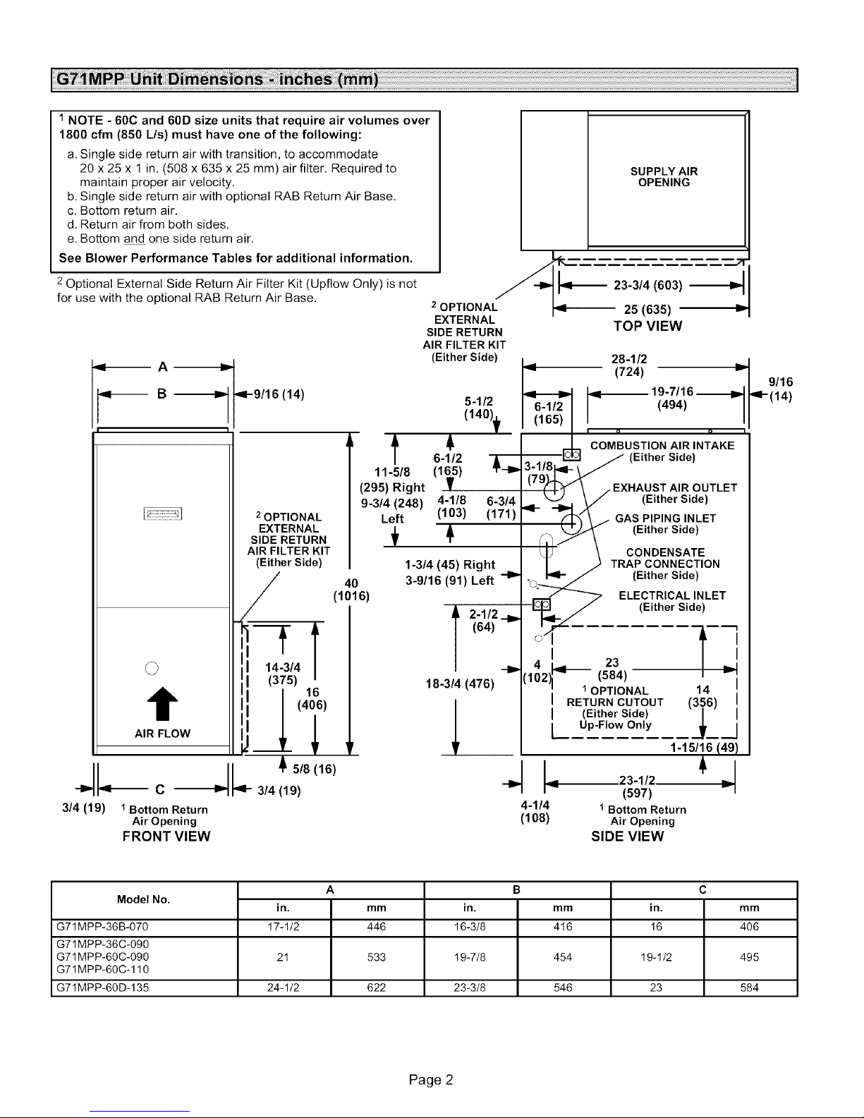
1NOTE - 60C and 60D size units that require air volumes over
1800 cfm (850 L/s) must have one of the following:
a. Single side return air with transition, to accommodate
20 x 25 x 1 in. (508 x 635 x 25 mm) air filter. Required to
maintain proper air velocity.
b. Single side return air with optional RAB Return Air Base.
c. Bottom return air.
d. Return air from both sides.
e. Bottom and one side return air.
See Blower Performance Tables for additional information.
SUPPLY AIR
OPENING
Optional External Side Return Air Filter Kit (Upflow Only) is not
for use with the optional RAB Return Air Base.
,,_ A -_
,_v----- B -_D,.
9-9/16 (14)
2OPTIONAL
EXTERNAL
SIDE RETURN
AIR FILTER KIT
(Either Side)
11-5/8
(295) Right
9-3/4 (248)
Left
40
(1016)
t
AIR FLOW
2OPTIONAL I_ 25 (635)
EXTERNAL
SIDE RETURN
AIR FILTER KIT
(Either Side)
5-1/2
(140)t
t
6-1/2
(1_5)
4-1/8 6-3/4
(103) (171)
1-3/4 (45) Right
3-9/16 (91) Left -I_
(64)
A 2-1/2 .__
18-3/4 (476) (102 (584) i
I_ 28-1/2
J_ (724)
r_ COMBUSTIONAIR INTAKE
.... _ _ (Either Side)
( Iy \ / EXHAUSTAIROUTLET
9- _/_ Av (Either Side)
_11_y\ (Either Side)
L _ TRAPCONNECTION
°Oo_ (Either Side)
_p_,ql__ - (Either side )
04- --
I 23 _
• 1OPTIONAL 14
J (Either Side)
L Up-Flow Only
I RETURN CUTOUT (3.._6)
23-3/4 (603)
TOP VIEW
1.9_ 19-7/16_
GAsP,P,NG,NLET
\ .r_CONDENSATE
_ ELECTRICAL INLET
5/8(16)
Jl.--c 4-
3/4 (19) 1Bottom Return 4-1/4 1 Bottom Return
FRONT VIEW SIDE VIEW
--J_- 314(19)
Air Opening (108) Air Opening
9/16
'q'- (14)
1-15/16 (49)
Model No.
G71MPP-36B-070 17-1/2 446 16-3/8 416 16 406
G71MPP-36C-090
G71MPP-60C-090 21 533 19-7/8 454 19-1/2 495
G71MPP-60C-110
G71MPP-60D-135 24-1/2 622 23-3/8 546 23 584
in. mm in. mm in. mm
A B C
Page 2
Page 3
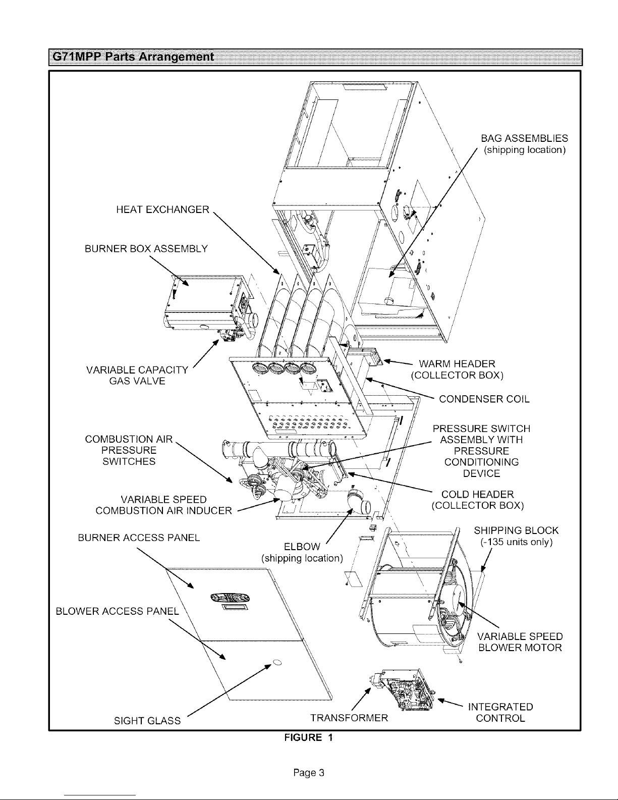
HEATEXCHANGER
BURNERBOXASSEMBLY
BAGASSEMBLIES
(shippinglocation)
VARIABLE CAPACITY
GAS VALVE
COMBUSTION AIR
PRESSURE
SWITCHES
VARIABLE SPEED
COMBUSTION AIRINDUCER
BURNER ACCESS PANEL
BLOWER ACCESS PANEL
/
WARM HEADER
(COLLECTOR BOX)
CONDENSER COIL
PRESSURE SWITCH
ASSEMBLY WITH
PRESSURE
CONDITIONING
DEVICE
COLD HEADER
(COLLECTOR BOX)
SHIPPING BLOCK
(-135unitsonly)
VARIABLE SPEED
BLOWER MOTOR
SIGHT GLASS
TRANSFORMER
FIGURE 1
Page 3
INTEGRATED
CONTROL
Page 4
TheG71MPPgasfurnaceisequippedwithavariable-ca-
pacity,variable-speedintegratedcontrol.Thiscontrolen-
surescompatibilitywithLennox'HarmonyIII'" zonecon-
trol system,as well as a thermostatwhichprovides
humiditycontrol.EachG71MPPisshippedreadyforinstal-
lationintheupflow,downflow,horizontalleftairdischarge
orhorizontalrightairdischargeposition.
Thefurnaceisequippedforinstallationinnaturalgasap-
plications.Aconversionkit(orderedseparately)isrequired
foruseinpropane/LPgasapplications.
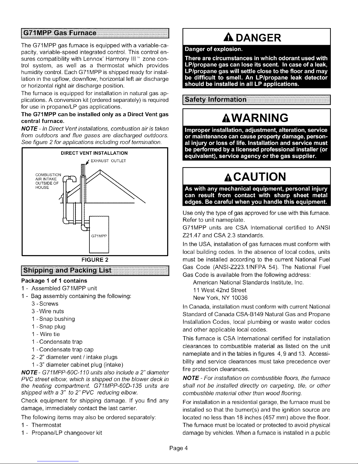
The G71MPP can be installed only as a Direct Vent gas
central furnace.
NOTE- In Direct Vent installations, combustion air is taken
from outdoors and flue gases are discharged outdoors.
See figure 2 for applications including roof termination.
DIRECT VENT INSTALLATION
EXHAUST OUTLET
DANGER
&WARNING
COMBUSTION
AIR INTAKE
OUTSIDE OF
HOUSE
FIGURE 2
Package 1 of 1 contains
1 - Assembled G71MPP unit
1 - Bag assembly containing the following:
3 - Screws
3 - Wire nuts
1 - Snap bushing
1 - Snap plug
1 - Wire tie
1 - Condensate trap
1 - Condensate trap cap
2 -2" diameter vent / intake plugs
1 -3" diameter cabinet plug (intake)
NOTE- G71MPP-60C-110 units also include a 2" diameter
PVC street elbow, which is shipped on the blower deck in
the heating compartment. G71MPP-60D-135 units are
shipped with a 3" to 2" PVC reducing elbow.
Check equipment for shipping damage. If you find any
damage, immediately contact the last carrier.
The following items may also be ordered separately:
1- Thermostat
1 - Propane/LP changeover kit
-&CAUTION
Use only the type of gas approved for use with this furnace.
Refer to unit nameplate.
G71MPP units are CSA International certified to ANSI
Z21.47 and CSA 2.3 standards.
In the USA, installation of gas furnaces must conform with
local building codes. In the absence of local codes, units
must be installed according to the current National Fuel
Gas Code (ANSl-Z223.1/NFPA 54). The National Fuel
Gas Code is available from the following address:
American National Standards Institute, Inc.
11 West 42nd Street
New York, NY 10036
In Canada, installation must conform with current National
Standard of Canada CSA-B149 Natural Gas and Propane
Installation Codes, local plumbing or waste water codes
and other applicable local codes.
This furnace is CSA International certified for installation
clearances to combustible material as listed on the unit
nameplate and in the tables in figures 4, 9 and 13. Accessi-
bility and service clearances must take precedence over
fire protection clearances.
NOTE- For installation on combustible floors, the furnace
shall not be installed directly on carpeting, tile, or other
combustible material other than wood flooring.
For installation in a residential garage, the furnace must be
installed so that the burner(s) and the ignition source are
located no less than 18 inches (457 mm) above the floor.
The furnace must be located or protected to avoid physical
damage by vehicles. When a furnace is installed in a public
Page 4
Page 5
garage,hangar,orotherbuildingthathasahazardousat-
mosphere,thefurnacemustbeinstalledaccordingtorec-
ommendedgoodpracticerequirementsandcurrentNa-
tionalFuelGasCodeorCSAB149standard.
NOTE - Furnace must be adjusted to obtain a temperature
rise within the range specified on the unit nameplate. Fail-
ure to do so may cause erratic limit operation.
This G71MPP furnace may be used as a high-static unit
heater. The G71MPP may also be installed in an aircraft
hangar in accordance with the Standard for Aircraft Han-
gars (ANSI/NFPA No. 408-1990).
Installation in parking structures must be in accordance
with the Standard for Parking Structures (ANSI/NFPA No.
88A-1991 ). Installation in repair garages must be in accor-
dance with the Standard for Repair Garages (ANSI/NFPA
No. 88B-1991).
This G71MPP furnace must be installed so that its electri-
cal components are protected from water.
When this furnace is used with cooling units, it shall be
installed in parallel with, or on the upstream side of, cooling
units to avoid condensation in the heating compartment.
With a parallel flow arrangement, a damper (or other
means to control the flow of air) must adequately prevent
chilled air from entering the furnace. If the damper is manu-
ally operated, it must be equipped to prevent operation of
either the heating or the cooling unit, unless it is in the full
HEAT or COOL setting.
When installed, this furnace must be electrically grounded
according to local codes. In addition, in the United States,
installation must conform with the current National Electric
Code, ANSI/NFPA No. 70. The National Electric Code
(ANSI/NFPA No. 70) is available from the following ad-
dress:
National Fire Protection Association
1 Battery March Park
Quincy, MA 02269
In Canada, all electrical wiring and grounding for the unit
must be installed according to the current regulations of the
Canadian Electrical Code Part I (CSA Standard C22.1)
and/or local codes.
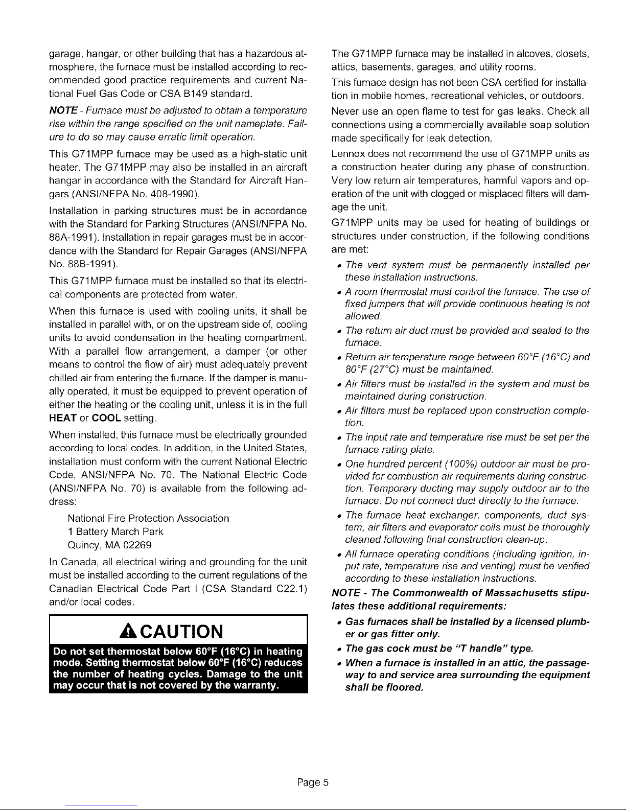
A CAUTION
The G71MPP furnace may be installed in alcoves, closets,
attics, basements, garages, and utility rooms.
This furnace design has not been CSA certified for installa-
tion in mobile homes, recreational vehicles, or outdoors.
Never use an open flame to test for gas leaks. Check all
connections using a commercially available soap solution
made specifically for leak detection.
Lennox does not recommend the use of G71MPP units as
a construction heater during any phase of construction.
Very low return air temperatures, harmful vapors and op-
eration of the unit with clogged or misplaced filters will dam-
age the unit.
G71MPP units may be used for heating of buildings or
structures under construction, if the following conditions
are met:
• The vent system must be permanently installed per
these installation instructions.
• A room thermostat must control the furnace. The use of
fixed jumpers that will provide continuous heating is not
aflowed.
• The return air duct must be provided and sealed to the
furnace.
• Return air temperature range between 60°F (16°C) and
80°F (27°C) must be maintained.
• Air filters must be installed in the system and must be
maintained during construction.
• Air filters must be replaced upon construction comple-
tion.
• The inputrate and temperature rise mustbe setperthe
furnace rating plate,
• One hundred percent (100%) outdoor air must be pro-
vided for combustion air requirements during construc-
tion. Temporary ducting may supply outdoor air to the
furnace. Do not connect duct directly to the furnace.
• The furnace heat exchanger, components, duct sys-
tem, air filters and evaporator coils must be thoroughly
cleaned following final construction clean-up.
• All furnace operating conditions (including ignition, in-
put rate, temperature rise and venting) must be verified
according to these installation instructions.
NOTE - The Commonwealth of Massachusetts stipu-
lates these additional requirements:
• Gas furnaces shall be installed by a licensedplumb-
er or gas fitter only.
• The gas cock must be "T handle" type.
• When a furnace is installed in an attic, the passage-
way to and service area surrounding the equipment
shall be floored.
Page 5
Page 6
,-& WARNING
In addition to the requirements outlined previously, the fol-
lowing general recommendations must be considered
when installing a G71MPP furnace:
• Place the furnace as close to the center of the air dis-
tribution system as possible. The furnace should also be
located close to the chimney or vent termination point.
• When the furnace is installed in an attic or other insu-
lated space, keep insulation away from the furnace.
• When the furnace is installed in an unconditioned
space, consider provisions required to prevent freezing
of condensate drain system.
,&,CAUTION
These instructions are intended as a general guide and do
not supersede local codes in any way. Consult authorities
having jurisdiction before installation.
SETTING EQUIPMENT
UPFLOW APPLICATION
UNIT MUST BE LEVEL SIDE-TO-SIDE IN ALL APPLICATIONS.
HORIZONTAL APPLICATION
I
-&WARNING
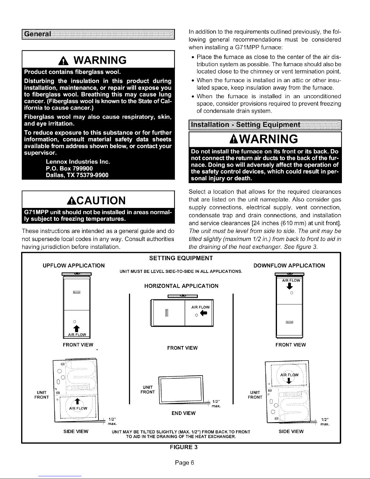
Select a location that allows for the required clearances
that are listed on the unit nameplate. Also consider gas
supply connections, electrical supply, vent connection,
condensate trap and drain connections, and installation
and service clearances [24 inches (610 mm) at unit front].
The unit must be level from side to side. The unit may be
tilted slightly (maximum 1/2 in.) from back to front to aid in
the draining of the heat exchanger. See figure 3.
DOWNFLOW APPLICATION
AIR FLOW
!,
I
O
t1"
AIR FLOW
FRONT VIEW
UNIT
FRONT
112"
max.
SIDE VIEW
UNIT MAY BE TILTED SLIGHTLY (MAX. 1/2") FROM BACK TO FRONT
FRONT VIEW
UNIT
FRONT
1/2"
I rflax,
END VIEW
TO AID IN THE DRAINING OF THE HEAT EXCHANGER.
FIGURE 3
Page 6
UNIT
FRONT
m
FRONT VIEW
©
1/2"
rflax.
SIDE VIEW
Page 7
NOTE - G71MPP-36B and -36C units with 1/2 hp blower
motors are equipped with three flexible legs and one rigid
leg, The rigid leg is equipped with a shipping bolt and a flat
white plastic washer (rather than the rubber mounting
grommet used with a flexible mounting leg), The bolt and
washer must be removed before the furnace is placed
into operation. After the bolt and washer have been re-
moved, the rigid leg will not touch the blower housing.
NOTE - G71MPP-60D-135 units are equipped with a ship-
ping pad under the blower housing. Remove the shipping
pad prior to operation.
Allow for clearances to combustible materials as indicated
on the unit nameplate, Minimum clearances for closet or al-
cove installations are shown in figures 4, 9 and 13,
WARNING
WARNING
Upflow Applications
The G71MPP gas furnace can be installed as shipped in
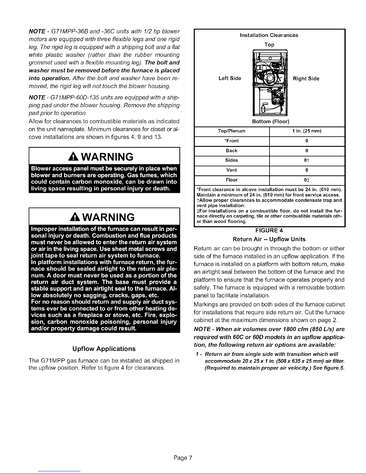
the upfiow position, Refer to figure 4 for clearances,
Installation Clearances
Top
LeftSide . _ RightSide
Bottom (Floor)
Top/Plenum 1 in. (25 ram)
*Front 0
Back 0
Sides 0-_
Vent 0
Floor 05
*Front clearance in alcove installation must be 24 in. (610 ram).
Maintain a minimum of 24 in. (610 ram) for front service access.
tAllow proper clearances to accommodate condensate trap and
vent pipe installation.
SFor installations on a combustible floor, do not install the fur-
nace directly on carpeting, tile or other combustible materials oth-
er than wood flooring.
FIGURE 4
Return Air -- Upflow Units
Return air can be brought in through the bottom or either
side of the furnace installed in an upfiow application. If the
furnace is installed on a platform with bottom return, make
an airtight seal between the bottom of the furnace and the
platform to ensure that the furnace operates properly and
safely. The furnace is equipped with a removable bottom
panel to facilitate installation,
Markings are provided on both sides of the furnace cabinet
for installations that require side return air. Cut the furnace
cabinet at the maximum dimensions shown on page 2,
NOTE - When air volumes over 1800 cfm (850 L/s) are
required with 60C or 60D models in an upflow applica-
tion, the following return air options are available:
1- Return air from single side with transition which will
accommodate 20x 25x I in. (508x 635x 25ram) air filter.
(Required to maintain proper air velocity.) See figure 5.
Page 7
Page 8
2 - Return air from single side with optional RAB Return
Air Base. See figure 7.
3 - Return air from bottom.
4 - Return air from both sides.
5 - Return air from bottom and one side.
Refer to Engineering Handbook for additional information.
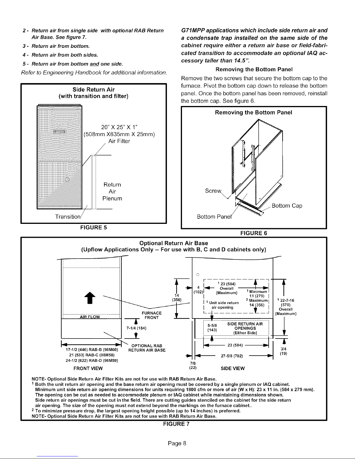
Side Return Air
(with transition and filter)
20" X 25" X 1"
(508mm X635mm X 25mm)
Air Filter
Return
Air
Plenum
G71MPP applications which include side return air and
a condensate trap installed on the same side of the
cabinet require either a return air base or field-fabri-
cated transition to accommodate an optional IAQ ac-
cessory taller than 14.5'"
Removing the Bottom Panel
Remove the two screws that secure the bottom cap to the
furnace. Pivot the bottom cap down to release the bottom
panel. Once the bottom panel has been removed, reinstall
the bottom cap. See figure 6.
Removing the Bottom Panel
Screw,/
Cap
Bottom
FIGURE 5
FIGURE 6
Optional Return Air Base
(Upflow Applications Only -- For use with B, C and D cabinets only)
J
r 123(584) ---_-_
Overall
t
FURNACE
FRONT
_.t (Either Side)
17-1/2 (446) RAB-B (98M60) RETURN AIR BASE
21 (533) RAB-C (98M58) -I_ 27-5/8 (702) --I1,-
24-1/2 (622) RAB-D (98M59) 7/8
FRONT VIEW (22) SIDE VIEW
NOTE- Optional Side Return Air Filter Kits are not for use with RAB Return Air Base.
1 Both the unit return air opening and the base return air opening must be covered by a single plenum or IAQ cabinet.
Minimum unit side return air opening dimensions for units requiring 1800 cfm or more of air (W x H): 23 x 11 in. (584 x 279 ram).
The opening can be cut as needed to accommodate plenum or IAQ cabinet while maintaining dimensions shown.
Side return air openings must be cut in the field. There are cutting guides stenciled on the cabinet for the side return
air opening. The size of the opening must not extend beyond the markings on the furnace cabinet..
2 To minimize pressure drop, the largest opening height possible (up to 14 inches) is preferred.
NOTE- Optional Side Return Air Filter Kits are not for use with RAB Return Air Base.
t4
(356)
(Maximum) 1Minimu_ I
I 11(279) I
I air opening
' 1 Unit side return 14_56) i
5-5/8 SIDE RETURN AIR
(143) OPENINGS
2 Maximum I
t-
-- 23 (584)OPTIONAL RAB
f
122-7-16
(570)
Overall
(Maximum)
_l
-T
3/4
(19)
FIGURE 7
Page 8
Page 9
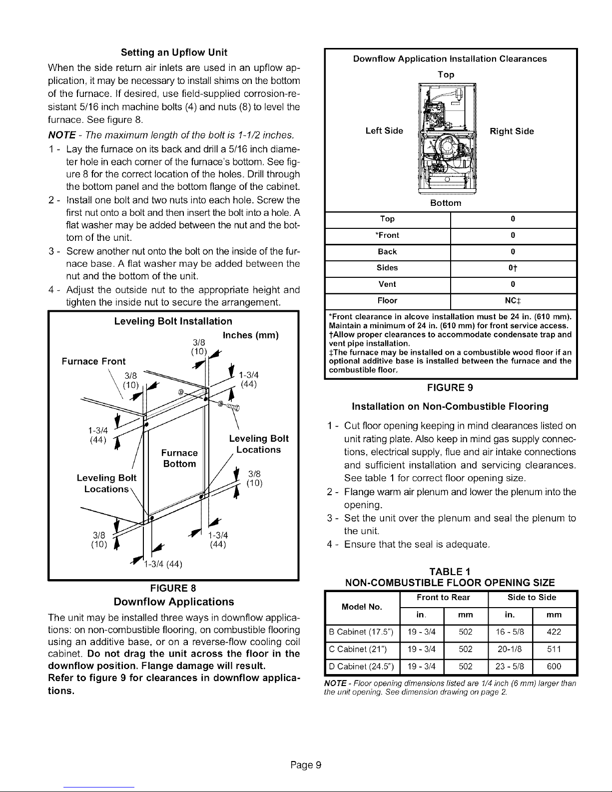
SettinganUpflowUnit
Whenthesidereturnairinletsareusedinanupflowap-
plication,itmaybenecessarytoinstallshimsonthebottom
ofthefurnace.Ifdesired,usefield-suppliedcorrosion-re-
sistant5/16inchmachinebolts(4)andnuts(8)tolevelthe
furnace,Seefigure8,
NOTE - The maximum length of the bolt is 1-1/2 inches.
1 - Lay the furnace on its back and drill a 5/16 inch diame-
ter hole in each corner of the furnace's bottom, See fig-
ure 8 for the correct location of the holes, Drill through
the bottom panel and the bottom flange of the cabinet.
2 - Install one bolt and two nuts into each hole. Screw the
first nut onto a bolt and then insert the bolt into a hole. A
flat washer may be added between the nut and the bot-
tom of the unit.
3 - Screw another nut onto the bolt on the inside of the fur-
nace base. A flat washer may be added between the
nut and the bottom of the unit,
4 - Adjust the outside nut to the appropriate height and
tighten the inside nut to secure the arrangement,
Leveling Bolt Installation
Inches (mm)
3/8
Furnace Front _¢
3/8 1-3/4
(44)
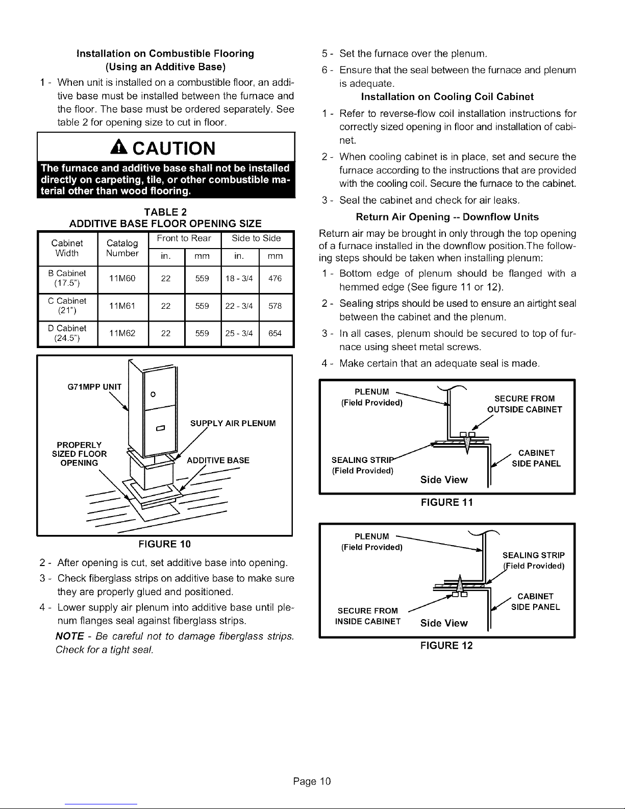
Downflow Application Installation Clearances
Top
LeftSide _ RightSide
Boffom
Top 0
*Front 0
Back 0
Sides 0t
Vent 0
Floor NC$
*Front clearance in alcove installation must be 24 in. (610 ram).
Maintain a minimum of 24 in. (610 ram) for front service access.
tAllow proper clearances to accommodate condensate trap and
vent pipe installation.
SThe furnace may be installed on a combustible wood floor if an
optional additive base is installed between the furnace and the
combustible floor.
FIGURE 9
1-3/4
(44)
Furnace
Bottom
Leveling Bolt
Locati,
3/8 1-3/4
(10) (44)
I-3/4 (44)
Leveling Bolt
Locations
3/8
(10)
FIGURE 8
Downflow Applications
The unit may be installed three ways in downflow applica-
tions: on non-combustible flooring, on combustible flooring
using an additive base, or on a reverse-flow cooling coil
cabinet. Do not drag the unit across the floor in the
downflow position. Flange damage will result.
Refer to figure 9 for clearances in downflow applica-
tions.
Installation on Non-Combustible Flooring
1 - Cut floor opening keeping in mind clearances listed on
unit rating plate. Also keep in mind gas supply connec-
tions, electrical supply, flue and air intake connections
and sufficient installation and servicing clearances,
See table 1 for correct floor opening size.
2 - Flange warm air plenum and lower the plenum into the
opening.
3 - Set the unit over the plenum and seal the plenum to
the unit,
4 - Ensure that the seal is adequate,
TABLE 1
NON-COMBUSTIBLE FLOOR
Model No.
B Cabinet (17.5") 502
CCabinet(21") 502
DCabinet(24.5") 502
NOTE - Floor opening dimensions listed are 1/4 inch (6 mm) larger than
the unit opening. See dimension drawing on page 2.
Front to Rear
in.
19 - 3/4
19 - 3/4
19 - 3/4
mm
)PENING SIZE
Side to Side
in. mm
16 - 5/8 422
20-1/8 511
23 - 5/8 600
Page 9
Page 10
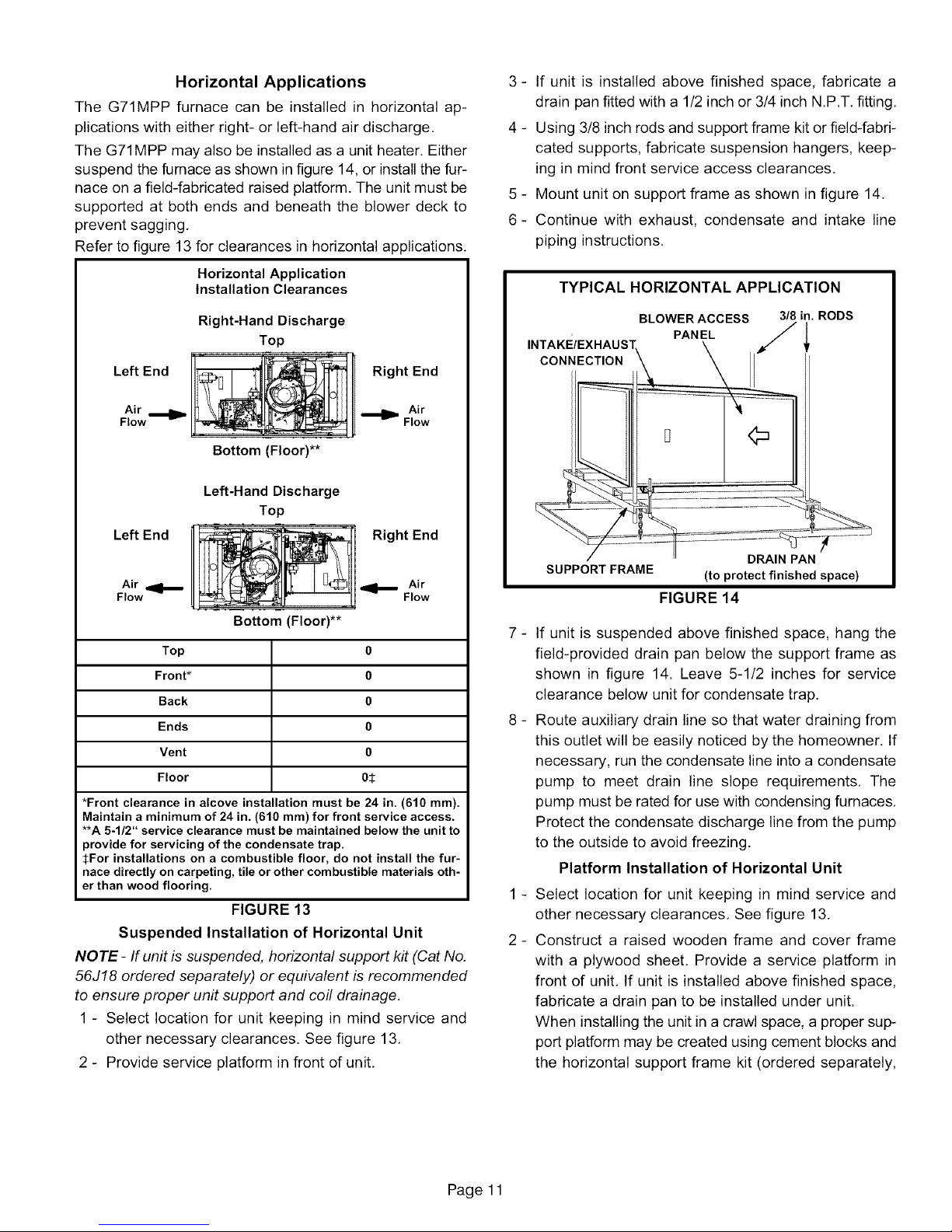
Installation on Combustible Flooring
(Using an Additive Base)
1 - When unit is installed on a combustible floor, an addi-
tive base must be installed between the furnace and
the floor, The base must be ordered separately. See
table 2 for opening size to cut in floor.
AkCAUTION
TABLE 2
ADDITIVE BASE FLOOR OPENING SIZE
Cabinet
Width
B Cabinet
(17.5")
C Cabinet
(21")
D Cabinet
(24.5")
Catalog
Number
11M60
11M61
11M62
Frontto Rear
in. mm
22 559
22 559
22 559
Side to Side
in. mm
18 - 3/4 476
22 - 3/4 578
25 - 3/4 654
5 - Set the furnace over the plenum,
6 - Ensure that the seal between the furnace and plenum
is adequate.
Installation on Cooling Coil Cabinet
1 - Refer to reverse-flow coil installation instructions for
correctly sized opening in floor and installation of cabi-
net,
2 - When cooling cabinet is in place, set and secure the
furnace according to the instructions that are provided
with the cooling coil, Secure the furnace to the cabinet,
3 - Seal the cabinet and check for air leaks,
Return Air Opening -- Downflow Units
Return air may be brought in only through the top opening
of a furnace installed in the downflow position.The follow-
ing steps should be taken when installing plenum:
1 - Bottom edge of plenum should be flanged with a
hemmed edge (See figure 11 or 12).
2 - Sealing strips should be used to ensure an airtight seal
between the cabinet and the plenum.
3 - In all cases, plenum should be secured to top of fur-
nace using sheet metal screws,
4 - Make certain that an adequate seal is made,
SUPPLY AIR PLENUM
G71MPP UNIT_ __T
PROPERLY
R ,VEBASE
FIGURE 10
2 - After opening is cut, set additive base into opening.
3 - Check fiberglass strips on additive base to make sure
they are properly glued and positioned,
4 - Lower supply air plenum into additive base until ple-
num flanges seal against fiberglass strips.
NOTE - Be careful not to damage fiberglass strips,
Check for a tight seal.
PLENUM --*.._ I"'t'_ "_
(Field Provided) _ SECURE FROM
• _L_UTSIDE CABINET
/ v II J CABINET
SEALING STRIP _ II./ SIDE PANEL
(Field Provided) ...... II
Side View II
FIGURE 11
PLENUM
(Field Provided_-._
SECURE FROM
INSIDE CABINET Side View
SEALING STRIP
,_/.J.Field Provided)
/ CABINET
, SIDE PANEL
FIGURE 12
Page 10
Page 11
Horizontal Applications
The G71MPP furnace can be installed in horizontal ap-
plications with either right- or left-hand air discharge,
The G71MPP may also be installed as a unit heater. Either
suspend the furnace as shown in figure 14, or install the fur-
nace on a field-fabricated raised platform. The unit must be
supported at both ends and beneath the blower deck to
prevent sagging,
Refer to figure 13 for clearances in horizontal applications,
3 - If unit is installed above finished space, fabricate a
drain pan fitted with a 1/2 inch or 3/4 inch N,P,T, fitting,
4 - Using 3/8 inch rods and support frame kit or field-fabri-
cated supports, fabricate suspension hangers, keep-
ing in mind front service access clearances.
5 - Mount unit on support frame as shown in figure 14,
6- Continue with exhaust, condensate and intake line
piping instructions,
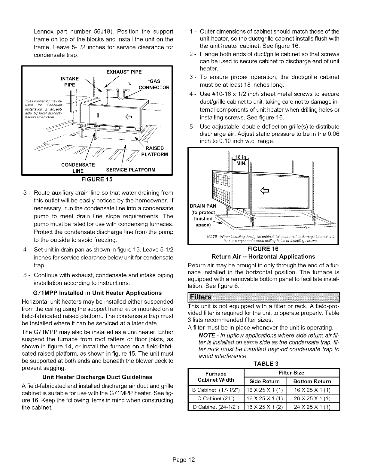
Horizontal Application
Installation Clearances
Right-Hand Discharge
Top
Left End
Air
Flow
Bottom (Floor)**
) / Right End
_ Air
• Flow
Left-Hand Discharge
Top
Left End
Air
Flow
Right End
Air
Flow
Bottom (Floor)**
Top 6
Front* 6
Back 6
Ends 6
Vent 6
Floor 65
*Front clearance in alcove installation must be 24 in. (610 ram).
Maintain a minimum of 24 in. (610 ram) for front service access.
**A 5-1/2" service clearance must be maintained below the unit to
provide for servicing of the condensate trap.
:_For installations on a combustible floor, do not install the fur-
nace directly on carpeting, tile or other combustible materials oth-
er than wood flooring.
FIGURE 13
Suspended Installation of Horizontal Unit
NOTE- If unit is suspended, horizontal support kit (Cat No.
56J18 ordered separately) or equivalent is recommended
to ensure proper unit support and coil drainage.
1 - Select location for unit keeping in mind service and
other necessary clearances. See figure 13,
2 - Provide service platform in front of unit,
TYPICAL HORIZONTAL APPLICATION
BLOWER ACCESS 3/8 in. RODS
PANEL l
CONNECTION
©
DRAIN PAN
SUPPORT FRAME (to protect finished space)
FIGURE 14
_
If unit is suspended above finished space, hang the
field-provided drain pan below the support frame as
shown in figure 14. Leave 5-1/2 inches for service
clearance below unit for condensate trap,
_
Route auxiliary drain line so that water draining from
this outlet will be easily noticed by the homeowner, If
necessary, run the condensate line into a condensate
pump to meet drain line slope requirements, The
pump must be rated for use with condensing furnaces,
Protect the condensate discharge line from the pump
to the outside to avoid freezing.
Platform Installation of Horizontal Unit
_
Select location for unit keeping in mind service and
other necessary clearances, See figure 13,
2-
Construct a raised wooden frame and cover frame
with a plywood sheet, Provide a service platform in
front of unit, If unit is installed above finished space,
fabricate a drain pan to be installed under unit.
When installing the unit in a crawl space, a proper sup-
port platform may be created using cement blocks and
the horizontal support frame kit (ordered separately,
Page 11
Page 12
Lennoxpartnumber56J18).Positionthe support
frameontopoftheblocksandinstalltheunitonthe
frame.Leave5-1/2inchesforserviceclearancefor
condensatetrap.
EXHAUST PIPE
*Gas connector may be
used for Canadian
installation ff accept-
able by local authority
having jurisdiction.
INTAKE
CONDENSATE
LINE SERVICE PLATFORM
FIGURE 15
*GAS
CONNECTOR
RAISED
1 - Outer dimensions of cabinet should match those of the
unit heater, so the duct/grille cabinet installs flush with
the unit heater cabinet. See figure 16.
2 - Flange both ends of duct/grille cabinet so that screws
can be used to secure cabinet to discharge end of unit
heater.
3- To ensure proper operation, the duct/grille cabinet
must be at least 18 inches long.
4 - Use #10-16 x 1/2 inch sheet metal screws to secure
duct/grille cabinet to unit, taking care not to damage in-
ternal components of unit heater when drilling holes or
installing screws. See figure 16,
5 - Use adjustable, double-deflection grille(s) to distribute
discharge air, Adjust static pressure to be in the 0.06
inch to 0.10 inch w.c. range.
3 - Route auxiliary drain line so that water draining from
this outlet will be easily noticed by the homeowner. If
necessary, run the condensate line into a condensate
pump to meet drain line slope requirements. The
pump must be rated for use with condensing furnaces.
Protect the condensate discharge line from the pump
to the outside to avoid freezing.
4 - Set unit in drain pan as shown in figure 15. Leave 5-1/2
inches for service clearance below unit for condensate
trap.
5 - Continue with exhaust, condensate and intake piping
installation according to instructions.
G71MPP Installed in Unit Heater Applications
Horizontal unit heaters may be installed either suspended
from the ceiling using the support frame kit or mounted on a
field-fabricated raised platform. The condensate trap must
be installed where it can be serviced at a later date.
The G71MPP may also be installed as a unit heater. Either
suspend the furnace from roof rafters or floor joists, as
shown in figure 14, or install the furnace on a field-fabri-
cated raised platform, as shown in figure 15. The unit must
be supported at both ends and beneath the blower deck to
prevent sagging.
Unit Heater Discharge Duct Guidelines
A field-fabricated and installed discharge air duct and grille
cabinet is suitable for use with the G71MPP heater. See fig-
ure 16, Keep the following items in mind when constructing
the cabinet,
DRAIN PA_
NOTE _ Wtlen installing duct/grille cabinet, take care not to damage internal unit
beater components wben drilling boles or installing screws.
FIGURE 16
Return Air -- Horizontal Applications
Return air may be brought in only through the end of a fur-
nace installed in the horizontal position. The furnace is
equipped with a removable bottom panel to facilitate instal-
lation. See figure 6.
This unit is not equipped with a filter or rack, A field-pro-
vided filter is required for the unit to operate properly. Table
3 lists recommended filter sizes,
A filter must be in place whenever the unit is operating.
NOTE - In upflow applications where side return air fil-
ter is installed on same side as the condensate trap, fil-
ter rack must be installed beyond condensate trap to
avoid interference.
TABLE 3
Furnace
Cabinet Width
B Cabinet (17-1/2")
C Cabinet (21")
D Cabinet (24-1/2")
Side Return Bottom Return
16X25Xl(1) 16X25Xl(1)
16X25Xl(1) 20X25Xl(1)
16X25Xl(2) 24X25Xl(1)
Filter Size
Page 12
Page 13
Useindustry-approvedstandardsto sizeandinstallthe
supplyandreturnairductsystem.Thiswillresultinaquiet
andlow-staticsystemthathasuniformairdistribution.
NOTE - Operation of this furnace in heating mode (indoor
blower operating at selected heating speed) with an exter-
nal static pressure which exceeds O.8 inches w.c. may re-
sult in erratic limit operation.
Supply Air Plenum
If the furnace is installed without a cooling coil, a removable
access panel should be installed in the supply air duct. The
access panel should be large enough to permit inspection
(by reflected light) of the heat exchanger for leaks after the
furnace is installed. If present, this access panel must al-
ways be in place when the furnace is operating and it must
not allow leaks into the supply air duct system.
Return Air Plenum
Return air must not be drawn from a room where this
furnace, or any other gas appliance (ie., a water heat-
er), is installed. When return air is drawn from a room, a
negative pressure is created in the room. If a gas appliance
is operating in a room with negative pressure, the flue prod-
ucts can be pulled back down the vent pipe and into the
room. This reverse flow of the flue gas may result in incom-
plete combustion and the formation of carbon monoxide
gas. This toxic gas might then be distributed throughout the
house by the furnace duct system.
Return air can be brought in through the bottom or either
side of the furnace. If a furnace with bottom return air is
installed on a platform, make an airtight seal between the
bottom of the furnace and the platform to ensure that the
unit operates properly and safely. Use fiberglass sealing
strips, caulking, or equivalent sealing method between the
plenum and the furnace cabinet to ensure a tight seal. If a
filter is installed, size the return air duct to fit the filter frame.
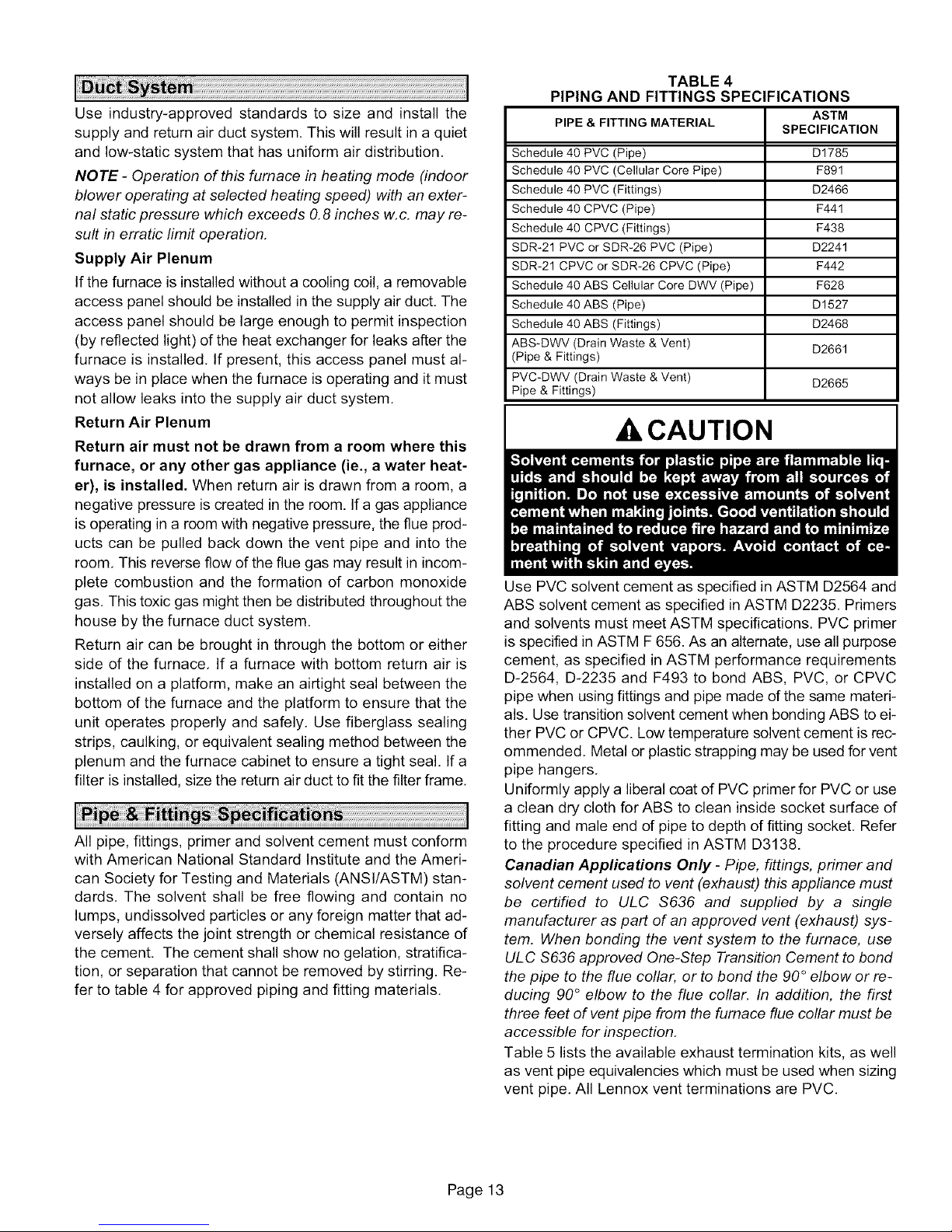
All pipe, fittings, primer and solvent cement must conform
with American National Standard Institute and the Ameri-
can Society for Testing and Materials (ANSI/ASTM) stan-
dards. The solvent shall be free flowing and contain no
lumps, undissolved particles or any foreign matter that ad-
versely affects the joint strength or chemical resistance of
the cement. The cement shall show no gelation, stratifica-
tion, or separation that cannot be removed by stirring. Re-
fer to table 4 for approved piping and fitting materials.
TABLE 4
PIPING AND FITTINGS SPECIFICATIONS
PIPE & FITTING MATERIAL
Schedule 40 PVC (Pipe) D1785
Schedule 40 PVC (Cellular Core Pipe) F891
Schedule 40 PVC (Fittings) D2466
Schedule 40 CPVC (Pipe) F441
Schedule 40 CPVC (Fittings) F438
SDR-21 PVC or SDR-26 PVC (Pipe) D2241
SDR-21 CPVC or SDR-26 CPVC (Pipe) F442
Schedule 40 ABS Cellular Core DWV (Pipe) F628
Schedule 40 ABS (Pipe) D1527
Schedule 40 ABS (Fittings) D2468
ABS-DWV (Drain Waste & Vent) D2661
(Pipe & Fittings)
PVC-DWV (Drain Waste & Vent) D2665
Pipe & Fittings)
ASTM
SPECIFICATION
_ CAUTION
Use PVC solvent cement as specified in ASTM D2564 and
ABS solvent cement as specified inASTM D2235. Primers
and solvents must meet ASTM specifications. PVC primer
is specified in ASTM F656. As an alternate, use all purpose
cement, as specified in ASTM performance requirements
D-2564, D-2235 and F493 to bond ABS, PVC, or CPVC
pipe when using fittings and pipe made d the same materi-
als. Use transition solvent cement when bonding ABS to ei-
ther PVC or CPVC. Low temperature solvent cement is rec-
ommended. Metal or plastic strapping may be used for vent
pipe hangers.
Uniformly apply a liberal coat of PVC primer for PVC or use
a clean dry cloth for ABS to clean inside socket surface of
fitting and male end d pipe to depth of fitting socket. Refer
to the procedure specified in ASTM D3138.
Canadian Applications Only - Pipe, fittings, primer and
solvent cement used to vent (exhaust) this appliance must
be certified to ULC S636 and supplied by a single
manufacturer as part of an approved vent (exhaust) sys-
tem. When bonding the vent system to the furnace, use
ULC $636 approved One-Step Transition Cement to bond
the pipe to the flue collar, or to bond the 90 ° elbow or re-
ducing 90° elbow to the flue collar. In addition, the first
three feet of vent pipe from the furnace flue collar must be
accessible for inspection.
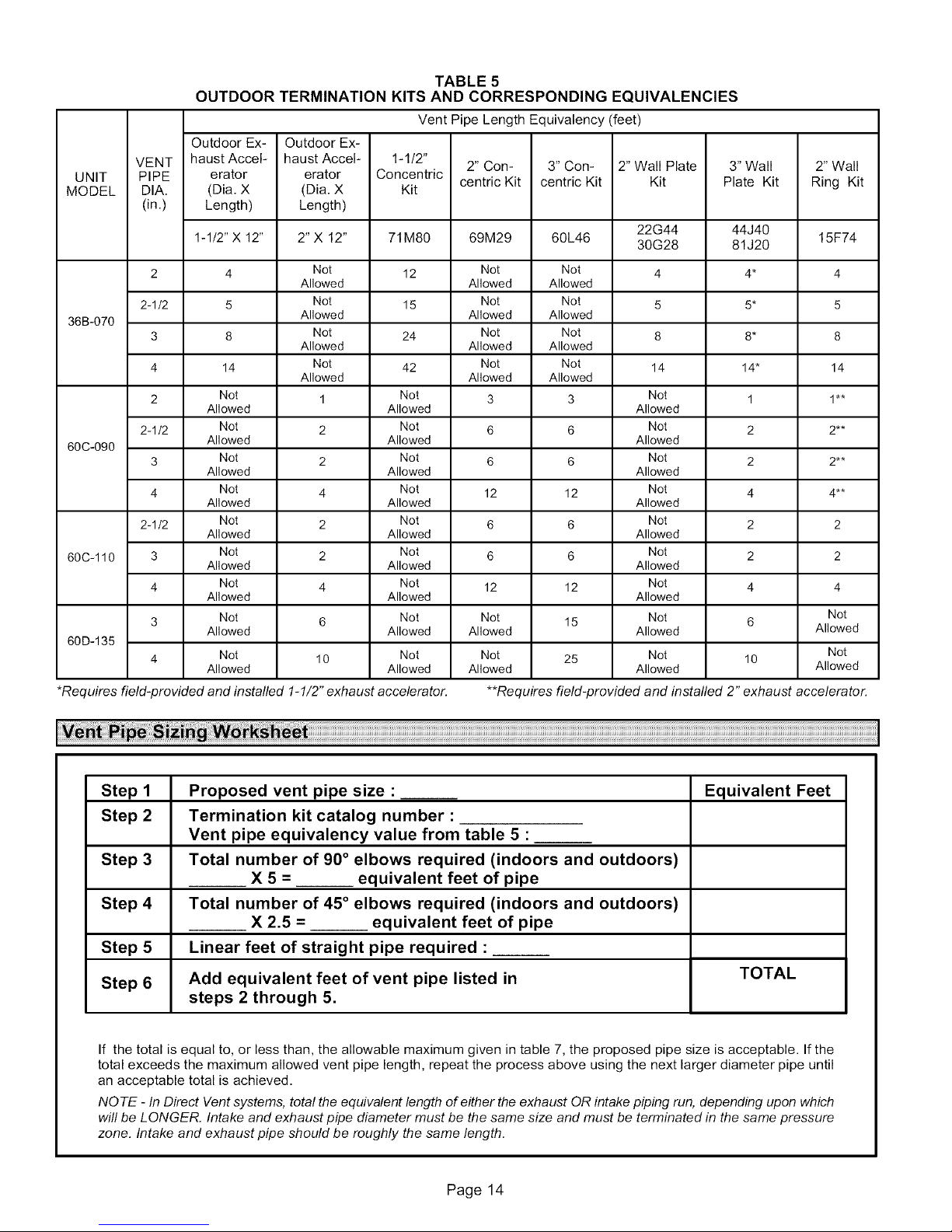
Table 5 lists the available exhaust termination kits, as well
as vent pipe equivalencies which must be used when sizing
vent pipe. All Lennox vent terminations are PVC.
Page 13
Page 14
OUTDOOR TERMINATION KITS AND CORRESPONDING EQUIVALENCIES
Outdoor Ex- Outdoor Ex-
VENT haust Accel- haust Accel- 1-112"
UNIT PIPE erator erator Concentric
MODEL DIA. (Dia. X (Dia. X Kit
(in.) Length) Length)
1-1/2" X 12" 2"X 12" 71M80 69M29 60L46 30G28 81J20 15F74
TABLE 5
Vent Pipe Length Equivalency (feet)
2" Con- 3" Con- 2" Wall Plate 3" Wall 2" Wall
centric Kit centric Kit Kit Plate Kit Ring Kit
22G44 44J40
2 4 Not 12 Not Not 4 4* 4
2-1/2 5 Not 15 Not Not 5 5* 5
36B-070
60C-090
60C-110 3 Not 2 Not 6 6 Not 2 2
60D-135
*Requires field-provided and installed 1-1/2" exhaust accelerator.
3 8 Not 24 Not Not 8 8* 8
4 14 Not 42 Not Not 14 14" 14
2 Not 1 Not 3 3 Not 1 1"*
2-1/2 Not 2 Not 6 6 Not 2 2**
3 Not 2 Not 6 6 Not 2 2**
4 Not 4 Not 12 12 Not 4 4**
2-1/2 Not 2 Not 6 6 Not 2 2
4 Not 4 Not 12 12 Not 4 4
3 Not 6 Not Not 15 Not 6
4 Not 10 Not
Allowed Allowed Allowed
Allowed Allowed Allowed
Allowed Allowed Allowed
Allowed Allowed Allowed
Allowed Allowed Allowed
Allowed Allowed Allowed
Allowed Allowed Allowed
Allowed Allowed Allowed Allowed Allowed
Allowed Allowed
Allowed Allowed Allowed
Allowed Allowed Allowed
Allowed Allowed Allowed
Allowed Allowed Allowed
Not 25 Not 10
Allowed Allowed Allowed
**Requires field-provided and installed 2" exhaust accelerator.
Not
Not
Step 1
Step 2
Proposed vent pipe size :
Termination kit catalog number :
Vent pipe equivalency value from table 5 :
Step 3
Total number of 90 ° elbows required (indoors and outdoors)
X 5 = equivalent feet of pipe
Step 4
Total number of 45 ° elbows required (indoors and outdoors)
X 2.5 = equivalent feet of pipe
Step 5
Step 6
Linear feet of straight pipe required :
Add equivalent feet of vent pipe listed in
steps 2 through 5.
If the total is equal to, or less than, the allowable maximum given in table 7, the proposed pipe size is acceptable. If the
total exceeds the maximum allowed vent pipe length, repeat the process above using the next larger diameter pipe until
an acceptable total is achieved.
NOTE - In Direct Vent systems, total the equivalent length of either the exhaust OR intake piping run, depending upon which
will be LONGER. Intake and exhaust pipe diameter must be the same size and must be terminated in the same pressure
zone. Intake and exhaust pipe should be roughly the same length.
Equivalent Feet
TOTAL
Page 14
Page 15
The G71MPP can be installed only as a Direct Vent gas
central furnace.
NOTE- In Direct Vent installations, combustion air is taken
from outdoors and flue gases are discharged outdoors.
Intake and exhaust pipe sizing -- Size pipe according to
tables 6 and 7. Table 6 lists the minimum equivalent vent
pipe lengths permitted. Table 7 lists the maximum equiva-
lent pipe lengths permitted.
Maximum vent length is defined as:
Total length (linear feet) of pipe,
Plus Equivalent length (feet) of fittings,
Plus Equivalent length (feet) of termination.
NOTE- Include ALL pipe and ALL fittings, both indoors
and outdoors. Measure equivalent length of intake and
exhaust pipe separately. Use the greater of the two
lengths to determine vent pipe diameter to be used for
both intake and exhaust.
Regardless of the diameter of pipe used, the standard roof
and wall terminations described in section Exhaust Piping
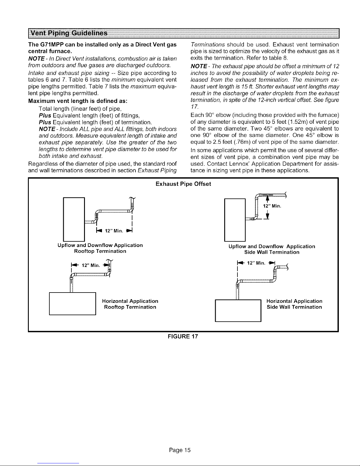
Exhaust Pipe Offset
Terminations should be used. Exhaust vent termination
pipe is sized to optimize the velocity of the exhaust gas as it
exits the termination, Refer to table 8,
NOTE- The exhaust pipe should be offset a minimum of 12
inches to avoid the possibility of water droplets being re-
leased from the exhaust termination, The minimum ex-
haust vent length is 15 ft, Shorter exhaust vent lengths may
result in the discharge of water droplets from the exhaust
termination, in spite of the 12-inch vertical offset. See figure
17,
Each 90° elbow (including those provided with the furnace)
of any diameter is equivalent to 5 feet (1,52m) of vent pipe
of the same diameter. Two 45° elbows are equivalent to
one 90° elbow of the same diameter, One 45° elbow is
equal to 2,5 feet (.76m) d vent pipe of the same diameter.
In some applications which permit the use of several differ-
ent sizes of vent pipe, a combination vent pipe may be
used. Contact Lennox' Application Department for assis-
tance in sizing vent pipe in these applications.
I
I
_'q 12" Min. t1_
m
Upflow and Downflow Application
Rooftop Termination
"br"
12" Min. "1_1
I
Horizontal Application
Rooftop Termination
m
Upflow and Downflow Application
Side Wall Termination
_1- 12" Min. -I_
I
I)
Horizontal Application
Side Wall Termination
I
FIGURE 17
Page 15
Page 16
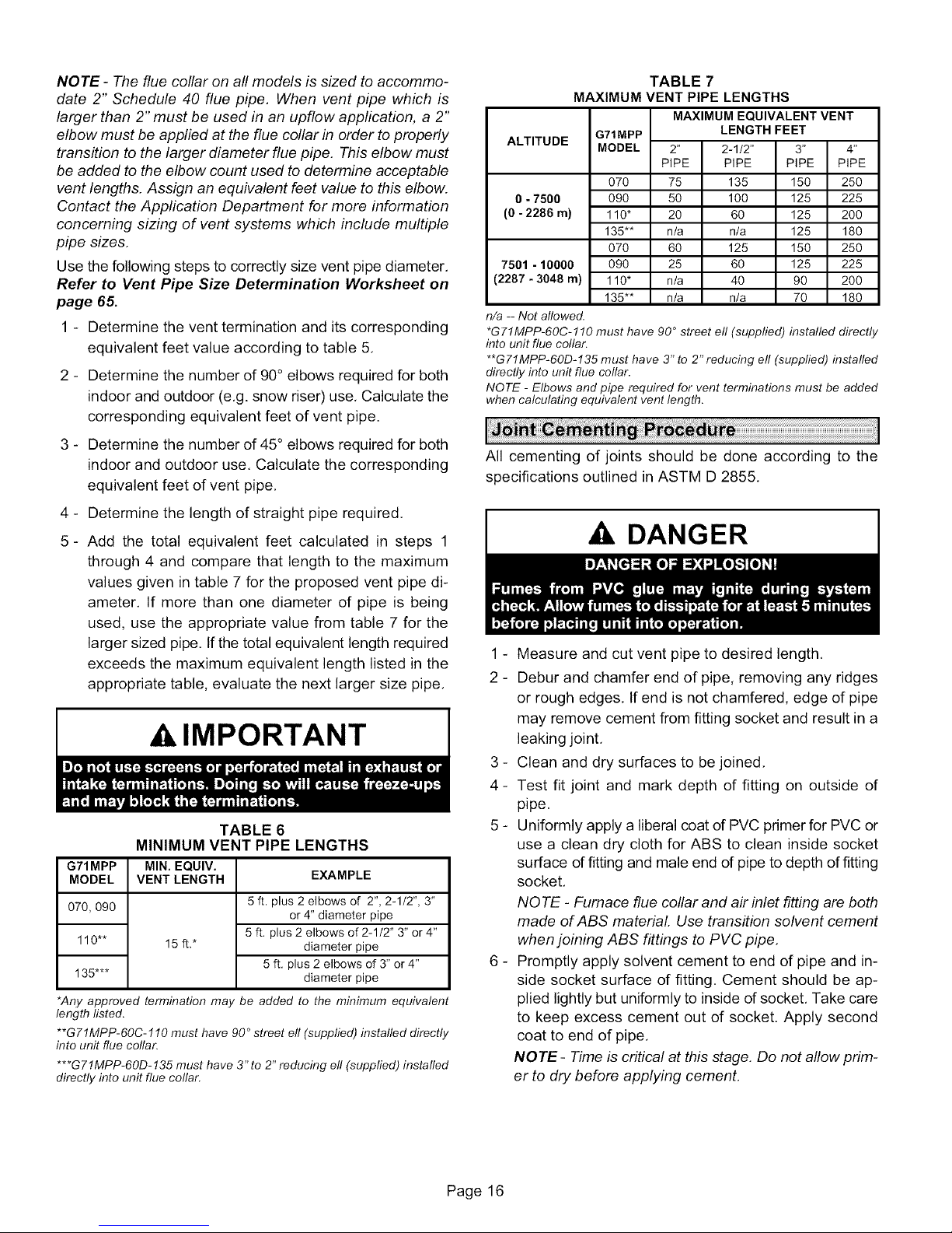
NOTE - The flue collar on all models is sized to accommo-
date 2" Schedule 40 flue pipe, When vent pipe which is
larger than 2" must be used in an upflow application, a 2"
elbow must be applied at the flue collar in order to properly
transition to the larger diameter flue pipe. This elbow must
be added to the elbow count used to determine acceptable
vent lengths. Assign an equivalent feet value to this elbow.
Contact the Application Department for more information
concerning sizing of vent systems which include multiple
pipe sizes.
Use the following steps to correctly size vent pipe diameter,
Refer to Vent Pipe Size Determination Worksheet on
page 65.
1 - Determine the vent termination and its corresponding
equivalent feet value according to table 5,
2 - Determine the number of 90° elbows required for both
indoor and outdoor (e,g. snow riser) use. Calculate the
corresponding equivalent feet of vent pipe.
TABLE 7
MAXIMUM VENT PIPE LENGTHS
MAXIMUM EQUIVALENT VENT
ALTITUDE
0 - 7500 090 50 100 125 225
(0 - 2286 m) 110" 20 60 125 200
7501 - 10000 090 25 60 125 225
(2287 - 3048 m) 110" n/a 40 90 200
n/a -- Not allowed.
*G71MPP-60C-110 must have 90° street eli (supplied) installed directly
into unit flue collar.
**G71MPP-60D-135 must have 3" to 2" reducing eli (supplied) installed
directly into unit flue collar.
NOTE - Elbows and pipe required for vent terminations must be added
when calculating equivalent vent length.
G71MPP LENGTH FEET
MODEL 2" 2-1/2" 3" 4"
PIPE PIPE PiPE PiPE
070 75 135 150 250
135"* n/a n/a 125 180
070 60 125 150 250
135"* n/a n/a 70 180
3 - Determine the number of 45° elbows required for both
indoor and outdoor use, Calculate the corresponding
equivalent feet of vent pipe,
4 - Determine the length of straight pipe required,
5- Add the total equivalent feet calculated in steps 1
through 4 and compare that length to the maximum
values given in table 7 for the proposed vent pipe di-
ameter. If more than one diameter of pipe is being
used, use the appropriate value from table 7 for the
larger sized pipe, If the total equivalent length required
exceeds the maximum equivalent length listed in the
appropriate table, evaluate the next larger size pipe.
AIMPORTANT
TABLE 6
MINIMUM VENT PIPE LENGTHS
G71MPP
MODEL
070,090
110"*
135"**
*Any approved termination ma
length listed.
**G71MPP-60C-110 must have 90 ° street eli (suppfied) installed directly
into unit flue collar.
***G71MPP-60D-135 must have 3" to 2" reducing eli (supplied) installed
directly into unit flue collar.
MIN. EQUIV.
VENT LENGTH
15 ft.*
EXAMPLE
5 ft. plus 2 elbows of 2", 2-1/2", 3"
or 4" diameter pipe
5 ft. plus 2 elbows of 2-1/2" 3" or 4"
diameter pipe
5 ft, plus 2 elbows of 3" or 4"
diameter pipe
, be added to the minimum equivalent
All cementing of joints should be done according to the
specifications outlined in ASTM D 2855.
,& DANGER
1 - Measure and cut vent pipe to desired length,
2 - Debur and chamfer end of pipe, removing any ridges
or rough edges, If end is not chamfered, edge of pipe
may remove cement from fitting socket and result in a
leaking joint,
3 - Clean and dry surfaces to be joined,
4- Test fit joint and mark depth of fitting on outside of
pipe,
5 - Uniformly apply a liberal coat of PVC primer for PVC or
use a clean dry cloth for ABS to clean inside socket
surface of fitting and male end of pipe to depth of fitting
socket,
NOTE - Furnace flue collar and air inlet fitting are both
made of ABS material. Use transition solvent cement
when joining ABS fittings to PVC pipe,
6 - Promptly apply solvent cement to end of pipe and in-
side socket surface of fitting. Cement should be ap-
plied lightly but uniformly to inside of socket, Take care
to keep excess cement out of socket, Apply second
coat to end of pipe,
NOTE- Time is critical at this stage. Do not allow prim-
er to dry before applying cement.
Page 16
Page 17
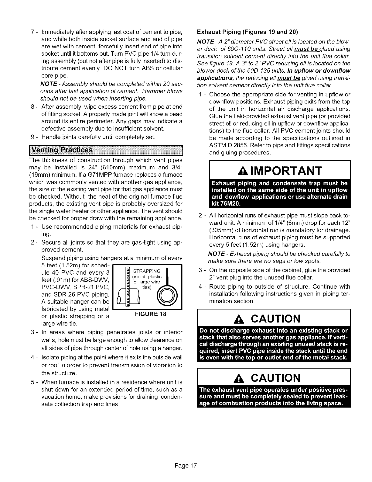
7- Immediatelyafterapplyinglastcoatofcementtopipe,
andwhilebothinsidesocketsurfaceandendofpipe
arewetwithcement,forcefullyinsertendofpipeinto
socketuntilitbottomsout.TurnPVCpipe1/4turndur-
ingassembly(butnotafterpipeisfullyinserted)todis-
tributecementevenly.DONOTturnABSorcellular
corepipe.
NOTE - Assembly should be completed within 20 sec-
onds after last appfication of cement. Hammer blows
should not be used when inserting pipe.
8 - After assembly, wipe excess cement from pipe at end
of fitting socket. A properly made joint will show a bead
around its entire perimeter. Any gaps may indicate a
defective assembly due to insufficient solvent.
9 - Handle joints carefully until completely set.
The thickness of construction through which vent pipes
may be installed is 24" (610mm) maximum and 3/4"
(19mm) minimum. If a G71MPP furnace replaces a furnace
which was commonly vented with another gas appliance,
the size d the existing vent pipe for that gas appliance must
be checked. Without the heat of the original furnace flue
products, the existing vent pipe is probably oversized for
the single water heater or other appliance. The vent should
be checked for proper draw with the remaining appliance.
1 - Use recommended piping materials for exhaust pip-
ing.
2 - Secure all joints so that they are gas-tight using ap-
proved cement.
Suspend piping using hangers at a minimum of every
5 feet (1.52m) for sched-
ule 40 PVC and every 3
feet (.91m) for ABS-DWV,
PVC-DWV, SPR-21 PVC,
and SDR-26 PVC piping.
A suitable hanger can be
fabricated by using metal
or plastic strapping or a
large wire tie.
3- In areas where piping penetrates joists or interior
walls, hole must be large enough to allow clearance on
all sides of pipe through center of hole using a hanger.
4 - Isolate piping at the point where it exits the outside wall
or roof in order to prevent transmission of vibration to
the structure.
5 - When furnace is installed in a residence where unit is
shut down for an extended period of time, such as a
vacation home, make provisions for draining conden-
sate collection trap and lines.
STRAPPING
(metal, plastic
large wire
ties)
FIGURE 18
Exhaust Piping (Figures 19 and 20)
NOTE- A 2" diameter PVC street ell is located on the blow-
er deck of 60C-110 units, Street ell must be_glued using
transition solvent cement directly into the unit flue collar.
See figure 19. A 3"to 2" PVC reducing ell is located on the
blower deck of the 60D-135 units, In upflow or downflow
applications, the reducing ell must be glued using transi-
tion solvent cement directly into the unit flue collar.
1 - Choose the appropriate side for venting in upflow or
downflow positions, Exhaust piping exits from the top
of the unit in horizontal air discharge applications.
Glue the field-provided exhaust vent pipe (or provided
street ell or reducing ell in upflow or downflow applica-
tions) to the flue collar, All PVC cement joints should
be made according to the specifications outlined in
ASTM D 2855. Refer to pipe and fittings specifications
and gluing procedures,
A, IMPORTANT
2 - All horizontal runs of exhaust pipe must slope back to-
ward unit. A minimum of 1/4" (6mm) drop for each 12"
(305mm) of horizontal run is mandatory for drainage.
Horizontal runs of exhaust piping must be supported
every 5 feet (1,52m) using hangers.
NOTE - Exhaust piping should be checked carefully to
make sure there are no sags or low spots.
3 - On the opposite side of the cabinet, glue the provided
2" vent plug into the unused flue collar,
4- Route piping to outside of structure, Continue with
installation following instructions given in piping ter-
mination section.
A, CAUTION
Ak CAUTION
Page 17
Page 18
PLUG
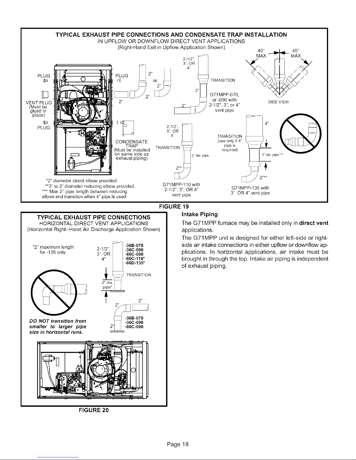
TYPICAL EXHAUST PIPE CONNECTIONS AND CONDENSATE TRAP INSTALLATION
IN UPFLOW OR DOWNFLOW DIRECT VENT APPLICATIONS
(Right-Hand Exit in Upflow Application Shown) 45°
2-1/2",
3", OR
4"
TRANSiTiON
MAX
45 °
MAX
t
VENT PLUG
(Must be
glued in
place)
PLUG
"2" diameter street elbow provided.
**3" to 2" diameter reducing elbow provided.
*** Max 2" pipe length between reducing
elbow and transition when 4" pipe is used.
TYPICAL EXHAUST PIPE CONNECTIONS
HORIZONTAL DIRECT VENT APPLICATIONS
(Horizontal Right-Hand Air Discharge Application Shown)
*2" maximum length -36B-070
for -135 only. -60C-090
2" or -090 with SIDE ViEW
CONDENSATE
TRAP
(Must be installed
on same side as
exhaust piping)
-36C-090
.60C.110"
.60D-135"
TRANSiTiON
G71 MPP-070,
2-1/2", 3", or4"
vent pipe
2-1/2", p:>_]
3":4OR _ TRANSmON
TRANSITION _ pipe is
G71MPP-110 with
2-1/2", 3", OR 4" G71MPP-135 with
vent pipe 3" OR 4" vent pipe
(useonly if 4"
required)
Ft /2 ....
FIGURE 19
Intake Piping
The G71MPP furnace may be installed only in direct vent
applications,
The G71MPP unit is designed for either left-side or right-
side air intake connections in either upflow or downflow ap-
plications. In horizontal applications, air intake must be
brought in through the top, Intake air piping is independent
of exhaust piping,
DO NOT transition from
smaller to larger pipe
size in horizontal runs.
,,1"36C'090
FIGURE 20
2"
-36B-070
-60C-090
IO
Page 18
Page 19
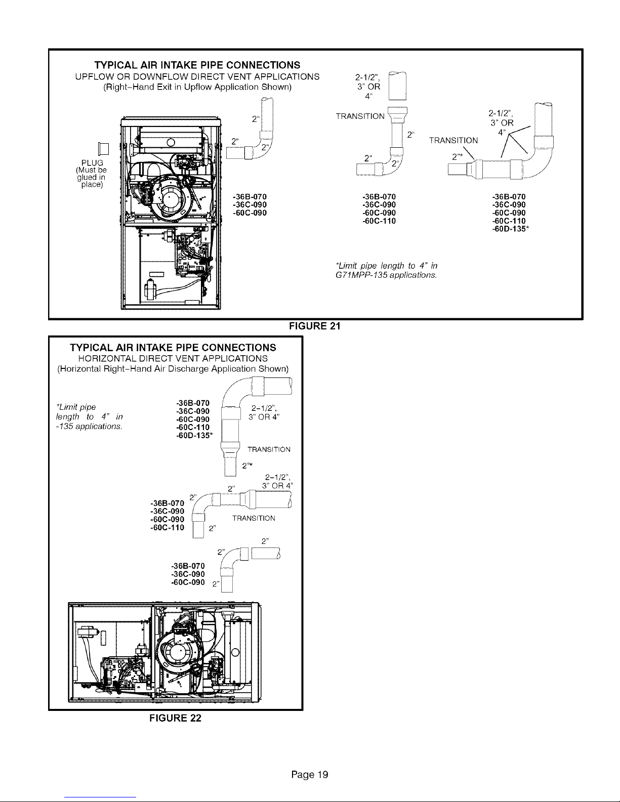
TYPICAL AIR INTAKE PIPE CONNECTIONS
UPFLOW OR DOWNFLOW DIRECT VENT APPLICATIONS
(Right-Hand Exit in Upfiow Application Shown)
3" OR
2-1/2", [:_
4'
PLUG
(Must be
glued in
place)
-36B-070
-36C-090
-60C-090
TYPICAL AIR INTAKE PIPE CONNECTIONS
HORIZONTAL DIRECT VENT APPLICATIONS
(Horizontal Right-Hand Air Discharge Application Shown)
*Limit pipe -36B-070
length to 4" in -60C-090
- 135 applications. -60C-110
-36C-090
-60D-135"
TRANSITION
2"*
2-1/2",
3" OR 4"
-36B-070
-36C-090
-60C-090
-60C-110
FIGURE 21
TRANSITION [_2"
-36B-070
-36C-090
-60C-090
-60C-110
*Limit pipe length to 4" in
G 71MPP-135 applications.
TRANSITION
-36B-070
-36C-090
-60C-090
-60C-110
-60D-135"
-36B-070
-36C-090
-60C-090 2,,L_
FIGURE 22
Page 19
Page 20
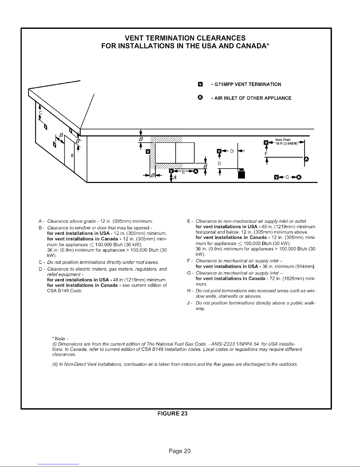
VENT TERMINATION CLEARANCES
FOR INSTALLATIONS IN THE USA AND CANADA*
[] - G71MPP VENT TERMINATION
O - AIR INLET OF OTHER APPLIANCE
D!
A - Clearance above grade - 12 in. (305mm) minimum.
B - Clearance to window or door that may be opened -
for vent installations in USA- 12 in (305mm) minimum.
for vent installations in Canada - 12 in. (305mm) mini-
mum for appliances _ 100,000 Btuh (30 kW);
36 in (09m) minimum for appliances > 100,000 Btuh (30
kW)
C - Do not position terminations directly under roof eaves.
D - Clearance to electric meters, gas meters, regulators, and
refief equipm ent -
for vent installations in USA -48 in (1219mm) minimum.
for vent installations in Canada - see current edition of
CSA B149 Code
* Note -
(I) Dimensions are from the current edition of The National Fuel Gas Code - ANSI-Z22& 1/NFPA 54 for USA installa-
tions. In Canada, refer to current edition of CSA B149 installation codes. Local codes or regulations may require different
clearances.
(11)In Non-Direct Vent installations, combustion air is taken from indoors and the flue gases are discharged to the outdoors.
E - Clearance to non-mechanical air supply inlet or outlet
for vent installations in USA -48 in. (1219mm) minimum
horizontal and below, 12 in, (305ram) minimum above.
for vent installations in Canada - 12 in. (305mm) mini-
mum for appliances _ 100,000 Btuh (30 kW);
36 in, (0.9m) minimum for appliances > 100,000 Btuh (30
kW).
F - Clearance to mechanical air supply inlet --
for vent installations in USA - 36 in. minimum (914mm).
G - Clearance to mechanical air supply inlet --
for vent installations in Canada - 72 in. (1829mm) mini-
mum.
H - Do notpoint terminations into recessed areas such as win-
dow wells, stairwells or alcoves.
J - Do not position terminations directly above a pubfic walk-
way.
FIGURE 23
Page 20
Page 21

Details of Intake and Exhaust Piping Terminations for
Direct Vent Installations
NOTE- In Direct Vent installations, combustion air is taken
from outdoors and flue gases are discharged to outdoors.
Intake and exhaust pipes may be routed either horizontally
through an outside wall or vertically through the roof. In at-
tic or closet installations, vertical termination through the
roof is preferred. Figures 24 through 32 show typical ter-
minations.
1 - Exhaust and intake exits must be in same pressure
zone. Do not exit one through the roof and one on the
side. Also, do not exit the intake on one side and the
exhaust on another side of the house or structure.
2 - Intake and exhaust pipes should be placed as close
together as possible at termination end (refer to il-
lustrations). Maximum separation is 3" (76mm) on roof
terminations and 6" (152mm) on side wall termina-
tions.
3 - If necessary, install a field-provided transition to adapt
larger vent pipe size to termination pipe size.
4 - On roof terminations, the intake piping should termi-
nate straight down using two 90° elbows (See figure
24).
5 - Exhaust piping must terminate straight out or up as
shown. In rooftop applications, a reducer may be re-
quired on the exhaust piping at the point where it exits
the structure to improve the velocity of exhaust away
from the intake piping. See table 8.
NOTE - Care must be taken to avoid recirculation of
exhaust back into intake pipe.
6 - On field supplied terminations for side wall exits, ex-
haust piping should extend a maximum of 12 inches
(305mm) beyond the outside wall unless supported.
Intake piping should be as short as possible. See fig-
ure 25.
7 - On field supplied terminations, the end of the exhaust
pipe must extend a minimum of 8" (203mm) beyond
the end of the intake pipe.
8 - If intake and exhaust piping must be run up a side wall
to position above snow accumulation or other obstruc-
tions, piping must be supported every 3 ft. (.9m) as
shown in figure 18. Refer to figure 28 for proper piping
method. In addition, the wall termination kit must be
extended for use in this application. See figure 31.
When exhaust and intake piping must be run up an
outside wall, the exhaust piping must be terminated
with pipe sized per table 8. The intake piping may be
equipped with a 90° elbow turndown. Using turndown
will add 5 feet (1.5m) to the equivalent length of the
pipe.
9 - Based on the recommendation of the manufacturer, a
multiple furnace installation may use a group of up to
four wall termination kits assembled together horizon-
tally, as shown in figure 30,
TABLE 8
EXHAUST PIPE TERMINATION SIZE REDUCTION
G71MPP
MODEL Exhaust Pipe Size Termination Pipe Size
070 2", 2-1/2", 3" or4" 1-1/2"
090 2", 2-1/2", 3" or4" 2"
110 2-1/2", 3" or4" 2"*
135 3" or 4" 2"*
*Approved 3" concentric termination kit terminates with 2-5/8" ID pipe.
8" (203)
MIN
t
3" (76) MAX.
--'_l _ PIPE PER TABLE 8.
SIZE TERMINATION
UNCONDITIONED
ATTIC SPACE
1/2" (13) FOAM
INSULATION IN
UNCONDITIONED
SPACE
Y
2" (50) or
3" (80) PVC
PROVIDE SUPPORT
FOR INTAKE AND
EXHAUST LINES
DIRECT VENT ROOF TERMINATION KIT
(15F75 or 44J41)
FIGURE 24
1/2" (13)ARMAFLEX I(unless supported)
INSULATION IN _ I=
UNCONDITIONED SPACE 1/2" (13)
R E_)R;(_'_iEMDAy "_
BE REQUIRED
TO ADAPT I 6" (152)
PIPE SIZE TO
LARGERTERMINATIoNVENT_ _UM
"=_ _ _ 2" (51) PVC
12" (305) MAX.
_, ARMAFLEX
V L,No
ou s,o JI
WALL I I MINIMUM I
Inches (rnm) TOP VIEW WALL RING KIT
(15F74)
FIGURE 25
/
Inches (mm)
INSULATION
Page 21
Page 22

EXHAUST 12" (305) ABOVE
TERMINATION AVERAGE SNOW
INTAKE
TERMINATION
EXHAUST INTAKE
ACCUMULATION
FIELD-PROVIDED
REDUCER MAY BE REQUIRED
TO ADAPT LARGER VENT
PIPE SIZE TO TERMINATION
Inches (ram)
DIRECT VENT CONCENTRIC ROOFTOP TERMINATION
(71M80, 69M29 or 60L46)
FIGURE 26
INTAKE
TERMINATION
Inches (ram)
EXHAUST
TERMINATION
EX.AUST
f
FIELD-PROVIDED
REDUCER MAY I_
BE REQUIRED TO
ADAPT LARGER
VENT PiPE SIZE
TO TERMINATION
12" (305) Min.
above grade.
f
EXHAUST VENT
INTAKE ('_
VENT J)r'_... t
(with optional/I L__J
_ Front View
elbow) /
1/2" (13) Foam Insulation
in Unconditioned Space Side View
PROVIDED EXHAUST VENT
REDUCER MAY
BE REQUIRED
TO ADAPT INTAKE
LARGER VENT VENT
PIPE SIZE TO | (with optional
FIELD- L
TERMINATION elbow)
Inches (ram) OUTSIDE WALL
DIRECT VENT WALL TERMINATION KIT
(22G44, 44J40, 30G28 or 81J20)
FIGURE 29
EXHAUST--_ [_)l L,__,_ /,\_)_ _-- '
_'_ _ _ _', "_'_'_ 12"
/ 1 127 III '
VENT "" 5: .... /2" (i 05)
,NTAKE-- <i II¢-:tI III::
VENT I°_°ll _° I°_°ll °_ " "I
(with optional
elbow /
Inches (mm)
18"MAX.
(457) "_ Front View
_>_._ EXHAUST VENT
DIRECT VENT CONCENTRIC WALL TERMINATION
(71 M80, 69M29 or 60L46)
FIGURE 27
Inches(ram)
UNCONDITIONED
SPACE
OUTSIDE WALL
PROVIDE SUPPORT ---_TERMINATION
FOR INTAKE AND / PIPE PER
EXHAUST LINES EVERY / TABLE 8.
36" (914)
FIELD-PROVIDED 12" (305) ABOVE
REDUCER MAY ACCUMULATION
BE REQUIRED TO
ADAPT LARGER
VENT PIPE SIZE
TO TERMINATION
1/2" (13) FOAM
INSULATION IN
UNCONDITIONED 1/2" (13) FOAM
SPACE INSULATION
DIRECT VENT WALL RING TERMINATION
See venting table 7 for maximum venting lengths with this arrangement.
12" (305) MAX. for 2" (51)
(unless supported) ,_11
SIZE
/
AVERAGE SNOW
SIDE VIEW
(15F74)
FIGURE 28
_1_-'-,-,_ INTAKE
Side View
OPTIONAL VENT TERMINATION FOR MULTIPLE UNIT
INSTALLATION OF DIRECT VENT WALL TERMINATION KIT (30G28)
__ VENT
_ (with optional
FIGURE 30
elbow)
Page 22
Page 23

INTAKE
AIR
12" (305) MAX. for 2" (51)
20" (508) MAX. for 3" (76)
(unless supported) Inches (ram)
//
//
//
f- 71- -- -Iq
(C_ 1 _ _ EXHAUST
i _-_- --J ..... IJ AIR
__11_[_/_ 8" (203) I
//
!1 II _ _ 12"(305)
)1 Minimum
iiiililili_!!iii!ii!ii!ii!ii!ii!ii!ii!ii!ii!i_!i!!i_i_ii_iiii_;_;!
ABOVEGRAOE
INTAKE
AIR
5"
(127
12"
COVER EXHAUST
VENT WITH
1/2" (13)
FOAM
INSULATION
EXHAUST
AIR
12" MIN.
(305)
Above Grade
GRADE
Side View
DIRECT VENT TERMINATION
WALL TERMINATION KIT (22G44, 44J40, 30G28 or 81J20) EXTENDED VENT FOR GRADE CLEARANCE
FIGURE 31
G71MPP DIRECT VENT APPLICATION
USING EXISTING CHIMNEY STRAIOHT-CUTOR
8 12
(203mm 30_,m)
INTAKE P_PE
INSULATION (opfl_al)
SHEET
METALTOP
PLATE
MINIMUM 12"
(305ram) ABOVE
ROOF
*SIZE TERMINATION
PIPE PER TABLE 8.
NOTE - Do not discharge exhaust gases directjy into any chimney or vent stack. If ver-
tical discharge through an existing unused chimney or stack is required, insert piping
inside chimney until the pipe open end is above top of chimney and terminate as illus-
trated. In any exterior portion of chimney, the exhaust vent must be insulated.
ANGLE-CUT IN DIRECTION
OF ROOF SLOPE *
EXHAUSTVENT
1_" (13ram)
WEATHERPROOF
INSULAT_N
SHOULDER OF FITQNGS
PROVIDE SUPPORT
OF PIPE ON TOP PLATE
i ALTERNATE
L--\:; ..,_._AKEP_PE
FIGURE 32
Condensate Piping
This unit is designed for either right- or left-side exit of con-
densate piping in either upfiow or downflow applications;
however, it must be installed on the same side of the unit as
the exhaust piping. In horizontal applications, the conden-
sate trap should extend below the unit. A 5-1/2" service
clearance is required for the condensate trap. Refer to fig-
ure 33 for condensate trap locations.
GRADE
Front View
NOTE- If necessary the condensate trap may be installed
in an alternate location in upflow applications using kit
number 76M20.
CONDENSATE TRAP LOCATIONS
(Unit shown in upf!ow position)
Horizontal
left and
optional
downfiow
Optional
upflow
O
Horizontal
_] right and
J optional
downflow
Optional
upf!ow
NOTE - In upflow applications where side return
air filter is installed on same side as the conden-
sate trap, filter rack must be installed beyond
condensate trap to avoid interference.
FIGURE 33
Page 23
Page 24

1- Determinewhichsidecondensatepipingwillexitthe
unit,Removeplugsfromthecondensatecollaratthe
appropriatelocationonthesideof theunit.
NOTE - The condensate trap is factory-shipped with
two rubber Q-rings and two rubber clean-out caps
installed. Check to make sure that these items are in
place before installing the trap assembly.
2- Install condensate trap onto the condensate collar.
Use provided HI/LO screws to secure two upper
flanges of the trap to the collar, Use provided sheet
metal screw to secure bottom trap flange to side of
unit, See figure 34,
NOTE - In upflow and downflow applications, con-
densate trap must be installed on the same side as
exhaust piping.
CAUTION
Condensate line must be sloped downward away from
condensate trap to drain, If drain level is above con-
densate trap, condensate pump must be used, Con-
densate drain line should be routed within the condi-
tioned space to avoid freezing of condensate and
blockage of drain line, If this is not possible, a heat
cable kit may be used on the condensate trap and line.
Heating cable kit is available from Lennox in various
lengths; 6 ft. (1.8m) - kit no. 26K68; 24 ft. (7.3m) - kit
no. 26K69; and 50 ft, (15.2m) - kit no, 26K70,
A CAUTION
5 - If unit will be started immediately upon completion of
installation, prime trap per procedure outlined in Unit
Start-Up section.
6- Glue the provided cap onto the unused condensate
drain line stub.
3- The grey-colored condensate trap (101661-01) pro-
vided with the unit is manufactured using ABS materi-
al. This is the only trap that is to be used with this unit,
Use ABS to PVC transition solvent cement to glue a
field-provided PVC coupling or PVC pipe to the trap.
Install a tee and vent pipe near the trap,
NOTE- The condensate trap drain stubs (both sides)
have an outer diameter which will accept a standard
3/4" PVC coupling. The inner diameter of each stub
will accept standard 1/2" diameter PVC pipe.
NOTE - Vinyl tubing may be used for condensate
drain. Tubing must be 1-1/4" QD X 1" ID and should be
attached to the drain stubs on the trap using a hose
clamp.
4 - Glue the field-provided drain line to the tee, Route the
drain line to an open drain. As an alternate, clear vinyl
tubing may be used to drain condensate away from
the trap. Secure the vinyl tubing to the drain stubs on
the trap using a hose clamp. Do not overtighten the
hose clamp.
CAP
\
O-RINGS
SCREW
CONDENSATE ASSEMBLY
HI/LO SCREWS
(DO NOT use power
driver. Hand4ighten
using screw driver.)
NIPPLE
COUPLING
_ CLEAN-OUT ACCESS
"_NDENSATE TRAP
(grey)
FIGURE 34
/VENT
NIPPLE
TEE
(both sides)
Page 24
Page 25

-&CAUTION
,IMPORTANT
AWARNING
1 - Gas piping may be routed into the unit through either
the left- or right-hand side. Supply piping enters into
the gas valve from the side of the valve as shown in
figures 36 and 37.
2 - When connecting gas supply, factors such as length of
run, number of fittings and furnace rating must be con-
sidered to avoid excessive pressure drop. Table 9 lists
recommended pipe sizes for typical applications.
NOTE - Use two wrenches when connecting gas pip-
ing to avoid transferring torque to the manifold.
3 - Gas piping must not run in or through air ducts, clothes
chutes, chimneys or gas vents, dumb waiters or eleva-
tor shafts. Center gas line through piping hole. Gas
line should not touch side of unit. See figures 36 and
37.
4 - Piping should be sloped 1/4 inch per 15 feet (6mm per
5.6m) upward toward the gas meter from the furnace.
The piping must be supported at proper intervals, ev-
ery 8 to 10 feet (2.44 to 3.05m), using suitable hangers
or straps. Install a drip leg in vertical pipe runs to serve
as a trap for sediment or condensate.
5 - A 1/8" N.P.T. plugged tap or pressure post is located
on the gas valve to facilitate test gauge connection.
See figures 44.
6 - In some localities, codes may require installation of a
manual main shut-off valve and union (furnished by in-
staller) external to the unit. Union must be of the
ground joint type.
MANUAL MAIN SHUT-OFF
VALVE WILL NOT HOLD
NORMAL TEST PRESSURE "_
CAP .------...._t-t
FURNACE
GAS VALVE
I
ISOLATE
FIGURE 35
Leak Check
After gas piping is completed, carefully check all piping
connections (factory- and field-installed) for gas leaks. Use
a leak detecting solution or other preferred means.
The furnace must be isolated from the gas supply system
by closing its individual manual shut-off valve during any
pressure testing of the gas supply system at pressures less
than or equal to 1/2 psig (3.48 kPa, 14 inches w.c.).
AIMPORTANT
AWARNING
Upflow Application AUTOMATIC
LeftSide Piping GASVALVE
(Standard) (with manual
MANUAL
MAIN SHUT-OFF
VALVE
!
GROUND
JOINT
UNION
DRIP LEG
shut-off valve)
Upflow Application
Right Side Piping
(Alternate)
MANUAL
J
FIELD
PROVIDED
AND INSTALLED
MAIN SHUT-OFF
VALVE
JOINT
UNION
DRIP LEG
Figure 36
Page 25
Page 26

MANUAL
MAIN SHUT-OFF
VALVE
GROUND
JOINT
UNION
DRIP LEG
Horizontal Applications
Possible Gas Piping Configerations
MANUAL
MAIN SHUT-OFF _
VALVE
J
GROUND
JOINT
J
• -q
UNION
DRIP LEG
Horizontal Application
Left-Side Air Discharge
Horizontal Application
Right-Side Air Discharge
LUlII
_31 II
_'-J 2-"
FIGURE 37
TABLE 9
GAS PIPE CAPACITY - FTZ/HR (kL/HR)
Nominal
Iron Pipe Size
-Inches(ram)
1/4
(6.35)
3/8
(9.53)
1/2
(12.7)
3/4
(19.05)
1
(25.4)
1-1/4
(31.75)
1-1/2
(38.1)
2
(50.8)
2-1/2
(63.5)
3
(76.2)
4
(101.6)
NO TE - Capacity given in cubic feet of gas per hour (kilo liters of gas per hour) and based on O.60 specific gravity gas.
Internal Length of Pipe-Feet(m)
Diameter 10 20 30 40 50 60 70
-Inches(ram) (3.048) (6.096) (9.144) (12.192) (15.240) (18.288) (21.336)
,364 43 29 24 20 18 16 15
(9.246) (1.13) (.82) (.68) (.57) (.51) (.45) (.42)
.493 95 65 52 45 40 36 33
(12.522) (2.69) (1.84) (1.47) (1.27) (1.13) (1.02) (.73)
.622 175 120 97 82 73 66 61
(17.799) (4.96) (3.40) (2.75) (2.32) (2.07) (1.87) (1.73)
.824 360 250 200 170 151 138 125
(20.930) (10.19) (7.08) (5.66) (4.81) (4.28) (3.91) (3.54)
1.049 680 465 375 320 285 260 240
(26.645) (19.25) (13.17) (10.62) (9.06) (8.07) (7.36) (6.80)
1,380 1400 950 770 660 580 530 490
(35.052) (39.64) (26.90) (21.80) (18.69) (16.42) (15.01) (13.87)
1.610 2100 460 1180 990 900 810 750
(40.894) (59.46) (41.34) (33.41) (28.03) (25.48) (22.94) (21.24)
2,067 3950 2750 2200 1900 1680 1520 1400
(52.502) (111.85) (77.87) (62.30) (53.80) (47.57) (43.04) (39.64)
2A69 6300 4350 3520 3000 2650 2400 2250
(67.713) (178.39) (123.17) (99.67) (84.95) (75.04) (67.96) (63.71)
3,068 11000 7700 6250 5300 4750 4300 3900
(77.927) (311.48) (218.03) (176.98) (150.07) (134.50) (121.76) (110.43)
4.026 23000 15800 12800 10900 9700 8800 8100
(102.260) (651.27) (447.39) (362.44) (308.64) (274.67) (249.18) (229.36)
8O
(24.384)
14
(.40)
31
(.88)
57
(1.61)
118
(3.34)
220
(6.23)
460
(13.o3)
690
(19.54)
13oo
(36.81)
2050
(58.05)
3700
(lO4.77)
7500
(212.37)
MANUAL
MAIN SHUT-OFF
VALVE
GROUND
JOINT
UNION
DRIP LEG
9O
(27.432)
13
(.37)
29
(.82)
53
(1.50)
110
(3.11)
205
(5.80)
430
(12.18)
650
(18.41)
1220
(34.55)
1950
(55.22)
3450
(97.69)
7200
(203.88)
100
(30.480)
12
(.34)
27
(.76)
50
(1.42)
103
(2.92)
195
(5.52)
400
(11.33)
620
(17.56)
1150
(32.56)
1850
(52.38)
3250
(92.03)
6700
(189.72)
Page 26
Page 27

ELECTROSTATIC DISCHARGE (ESD)
Precautions and Procedures
&CAUTION
INTERIOR MAKE-UP BOX INSTALLATION
MAKE-UP
BOX
Right Side
6
FIGURE 38
INTERIOR MAKE-UP BOX INSTALLATION
Left side
MAKE-UP
o BOX
FIGURE 39
The unit is equipped with a field make-up box. The make-
up box may be moved to the right side of the furnace to fa-
cilitate installation. If the make-up box is moved to the right
side, the excess wire must be pulled into the blower
compartment. Secure the excess wire to the existing harn-
ess to protect it from damage.
Refer to figure 40 and table 10 for field wiring and figure 41
for schematic wiring diagram and troubleshooting.
1 - Select circuit protection and wire size according to the
unit nameplate. The power supply wiring must meet
Class I restrictions.
2 - Holes are on both sides of the furnace cabinet to facili-
tate wiring.
3 - Install a separate disconnect switch (protected by ei-
ther fuse or circuit breaker) near the furnace so that
power can be turned off for servicing.
4 - Before connecting the thermostat or the power wiring,
check to make sure the wires will be long enough for
servicing at a later date. Remove the blower access
panel to check the length of the wire.
5- Complete the wiring connections to the equipment.
Use the provided unit wiring diagram and the field wir-
ing diagram shown in figure 40 and table 10. Use
18-gauge wire or larger that is suitable for Class II ra-
ting for thermostat connections.
6 - Electrically ground the unit according to local codes or,
in the absence of local codes, according to the current
National Electric Code (ANSI/NFPA No. 70) for the
USA and current Canadian Electric Code part 1 (CSA
standard C22.1) for Canada. A green ground wire is
provided in the field make-up box.
7 - One line voltage "EAC" 1/4" spade terminal is provided
on the furnace integrated control. Any electronic air
cleaner rated up to one amp can be connected to this
terminal with the neutral leg of the circuit being con-
nected to one of the provided neutral terminals. See
figure 42 for integrated control configuration. This ter-
minal is energized when the indoor blower is operating.
8- One line voltage *'HUM" 1/4" spade terminal is pro-
vided on the furnace integrated control. Any humidifier
rated up to one amp can be connected to this terminal
with the neutral leg of the circuit being connected to
one of the provided neutral terminals. See figure 42 for
integrated control configuration. This terminal is ener-
gized in the heating mode when the combustion air in-
ducer is operating.
9 - One 24V "H" terminal is provided on the furnace inte-
grated control terminal block. Any humidifier rated up
to 0.5 amp can be connected to this terminal with the
ground leg of the circuit being connected to either
ground or the "C" terminal. See figure 42 for integrated
control configuration.
Page 27
Page 28

10-Installtheroomthermostataccordingtotheinstruc-
tionsprovidedwiththethermostat,Seetable10for
thermostatconnections.If the furnaceis being
matchedwitha heatpump,referto theinstruction
packagedwiththedualfuelthermostat,
ThermostatSelection
TheG71MPPisdesignedtooperateinavariablerateca-
pacitymodeusingatwo-stagethermostat.TheG71MPP
willautomaticallyadjustfiringratebaseduponthermostat
cycletimes,Foroptimalperformance,Lennoxrecom-
mendsuseofa highqualityelectronicdigitalthermostat
withadjustablesettingsfor1ststage/ 2rid stage on / off dif-
ferentials and adjustable stage timers.
Lennox recommends the following two-stage thermostat
set-up for optimal variable rate capacity mode:
First heat stage differential set to 1/2 to 1 degree F; second
heat stage differential set to 1/2 or 1 degree F; second heat
TYPICAL G71MPP FIELD WIRING DIAGRAM
$102(2) COMBUSTION AIR
USE COPPER CONDUCTORS ONLY.
I I I FIELD INSTALLED CLASS 0 24V
z_ DH AND L TERHINALS ARE NOT USED
_GEE WIRE HARNESS TASLE TO MATCH
FIELD INSTALLED LINE VOLTAGE
FIELD SUPPLIED ACC WIRE
HARNESS T8 FURNACE SIZE
120V ACC G
LI -_--ili
$1
ROOM THERMOSTAT
I@@@®©@@I _
j " ' t3c_
',
i
,,
,,
i
i
Ii L .......
i
I ....
OUTDOOR
UNIT
_24_ INPUT
C
SWITCH LIMIT BACKUP GAS
PREGGUREGAG GlIB
@ SWITCH
-_ $1£8(G) _FLAME IGNITOR L_ _--_ $128(1)
LOW HEAT FLAME SENSOR 3159 FLAME /k_ LOW HEAT
PRESSURE ROLLOUT _P159 RDLLDUT PRESSURE
SWITCH SWITCH SWITCH SWITCH
E)-3156 INTEGRATED
s51E
0 CONTROL 3246
D
BF n [] P46
23456 183456
_),_)TO78 I I I I
SENSOR I I I 11 Ill II Z_ _
DDISCHAROE' 90DQ
stage upstage timer disabled, or set to maximum (1 hr mini-
mum).
Indoor Blower Speeds
1 - When the thermostat is set to "FAN ON," the indoor
blower will run continuously at a percentage of the sec-
ond-stage cooling speed when there is no cooling or
heating demand. The percentage is set using DIP
switches 6 and 7,
2 - When the G71MPP is running in the heating mode, the
integrated control will automatically adjust the blower
speed to match the furnace firing rate. This speed can
be adjusted up or down by 7,5% or 15% using DIP
switches 14 through 16 for the low heat speed and 17
through 19 for the high heat speed.
3 - When there is a cooling demand, the indoor blower will
run on the cooling speed designated by the positions
of DIP switches 8 through 11,
SECONDARY VALVE
BURNERS HIGH HEAT
A92
LIMIT cO
TRANSFORMER
PRESSURE
SOl(If
SECONDARY
TI
LIMIT
®
821(2)
SECONDARY
LIMIT
®
CB8 'I--
CIRCUIT
I--4---
L-:___
'I I I
L_ I I I
L_-_77 I
TERHINAL BOARD
r ..........
-i
I
I
I
t I
I i
BREAKER
POWER
CHOKE
L1B @
B3
INDOOR F_)
BLOWER
MOTOR
FIGURE 40
Page 28
Page 29

Thermostat
1Heat / 1 Cool
NOTE- Use DIP
switch 3 to set
second-stage
heat QN delay.
QFF-7 minutes.
0N-12 minutes.
1 Heat / 2 Cool
NOTE- Use DiP
switch 3 to set
second-stage
heat ON delay.
QFF- 7 minutes,
0N-12 minutes.
1 Heat / 2 Cool
with t'stat with
dehumidification
mode
NOTE- Use DIP
switch 3 to set
second-stage
heat ON delay.
QFF- 7 minutes,
0N-12 minutes.
TABLE 10
Field Wiring Applications
DIP Switch Settings and On-Board Links (figure 42)
W915
(Y1 to Y2) (DS to R)
DIP Switch 1
ON Intact Intact
ON
ON
Two-Stage cation or
Cooling Harmony
Cut
Cut
W914
Dehumidifi-
Heat Pumps
III'"
Intact
Cut
W951
(O to R)
Intact
Intact
Intact
Wiring Connections
S1 CONTROL OUTDOOR
T'STAT TERM. STRIP UNIT
@
®
® ® _)
® ®
® ® ®
@
® _,------Q
®
S1 CONTROL OUTDOOR
T'STAT TERM. STRIP UNIT
@
® ®
® ®
® ® ®
@ @- @
@. @ @
@
$1 CONTROL OUTDOOR
T'STAT TERM. STRIP UNIT
®
® ®
@ @---@
@ 4_---@
(_ @---@
* "R" required on some units.
Page 29
Page 30

Thermostat
2 Heat / 2 Cool
TABLE 10
Field Wiring Applications (Continued)
DIP Switch Settings and On-Board Links (figure 42)
W914
(DSto R)
Dehumidifi-
cation or
Harmony
III"
Intact
(O to R)
Heat Pumps
DIP Switch 1
OFF
W915
(Y1 to Y2)
Two-Stage
Cooling
Cut
W951
Intact
Wiring Connections
$1
T'STAT
CONTROL
TERM. STRIP
OUTDOOR
UNIT
@
2 Heat / 2 Cool
with t'stat with
dehumidifica-
tion mode
2 Heat/1 Cool
OFF
OFF
Cut
Intact
Cut
Intact
Intact
Intact
®
®
®-
®
®
@
@
@-
@
@
$1
T'STAT
®
®.
®
®.
@
$1 CONTROL OUTDOOR
T'STAT TERM. STRIP UNIT
CONTROL
TERM. STRIP
®
0----_
.@----@
_----_
@
OUTDOOR
®
@
@
UNIT
* "R" required on some units.
¢- ®.
®____.__
,:2)- ® ®
@
O- @ @
@
Page 30
Page 31

Thermostat
Dual Fuel
Single Stage
Heat Pump
ComfortSense
7000 L7724U
thermostat w/
dual fuel capa-
bilities
Capable of 2
stage gas heat
control
Dual Fuel
Two Stage
Heat Pump
ComfortSense
7000 L7724U
thermostat w/
dual fuel capa-
bilities
Capable of 2
stage gas heat
control
TABLE 10
Field Wiring Applications (Continued)
DIP Switch Settings and On-Board Link (figure 42)
W914
DIP Switch
DIP Switch 1
OFF
DIP Switch 1
OFF
W915
(Y1 to Y2)
Two-Stage
Cooling
Intact
Cut
(DS to R)
Dehumidifi-
cation or
Harmony
III ,r_
Intact
Intact
Heat Pumps
W951
(o to R)
Cut
Cut
Wiring Connections
L7724U TERM. STRIP
T'STAT
CONTROL HEAT PUMP
® ® ®
®
_)- -@ 67M41"
_. _.-o_
@ @ @
® ..... ..., @
® ® ®
@
®. ®
@ -_
® @
@ ® ®
® Flou,doo,
U Sellso,®
L7724U CONTROL TERM.
T'STAT STRIP HEAT PUMP
® ® ®
®
(_ _) 67M41"
@ @ ®
(:i:) _ @
@ @ ®
@ @
®. .®
* Connect W1 to W1 QNLYifusing defrost tempering kit 67M41
® _). o.,b,.e
@ 4b ®
Q se"s°'U
Page 31
Page 32

TYPICAL G71MPP WIRING DIAGRAM
_7_ ........F --- _ (_7 P_4¸ i\J _ .....
li - ._ S12_(2) $47 B,-- F_A_E IGNIT3R IR331 $41 St28<I>
...... ............................................................................................................................iiii.........................................i siii il
A92 LIMIT
SI $51 CONTROL ,J_46 _ _RANSFDRNER
ROOM T_ERNQSTAT
INTEGRATED TI @
SECONDARY
BLOWER SPEE_ CHARI WIRING HARNESS fABLE
i0i551 Oi PURPLE 7O,O0O 24O
i36C-OS_ i_:: _A_ _70¸@¸¸¸¸¸5_
....... [iOiSGi-03 YELLOW IilO,ObO[lO% I
60c:1!_o 101551 _.LUE 135_000 1GO
NOTE, SE E INSTALLATION INSTRUCTIONS FOR z_ LI3 USED ON IaP ONLY
PROCEDURE TO SET CORRECT BLOWER SPEED FOR _ FACTORY DEFAUI T IS F_ A 2
SPECIFIC COOLING TONNAGE BEING APPLIED, STAG{ THEROOSTAT
AND HEARING tEMPERATURE RISE DESIRED _ FIELD SUPPLIED ACC WIRE
IYP!CAL SYSTEM SHOWN FOR 2 NEAT/2 COOL /_us£ COPPER CONDUCTORS ONLY
WITH A CONVENTIONAl THERMOSTAT, SEE
INSTAl{AT[ON INSTRUCTIONS FOR CONNECTIONS 135 UNITS ONLY
10 DINER EQUIPNEN] AN9 ACCESSORIES
A T_O STAGE THERMOSTAT RUST BE USED _ITH rERMINALS ARE FOR FUTURE USE
THIS FURNACE IN VARIABLE CAPACITY MODE _N_y
REFER rB INSFALLATION INSFRUCIIBNS _OR _24V PO_ER PROVIDED FOR
MORE INFgRMAF[ON ON RECaNMENDED TYPES OF
THERMOSTATS AND SETTINGS FOR OPTIMA{ OPTIONAL HUMI_IFIER DURING
PART NO COLOR _TU_ RES_T
A SI13 IS USED ON 090, ii0, AND
_D[SCHARGE AN_ OUTDOOR AIR
HEAT DE_ANB
LINE VOLfAGE FELD INSTALLED
.... CLASS II VOLTAGE FZEID WIRING
_DENOTES OPTIONAL COMPONENTS
FIGURE 41
Page 32
WARNING
ELECTRIC S_CK HAZARD,CAN CAUSE INJURY
_R DEAT_UNIr NUSF BE GROUNDED IN ACCORDANCE
WIT_ NATIONAL AN_ LOCAL CODES¸
NOIE-
IF ANY WIRE IN T_[S APPLIANCE ;S R_PLACED,IT
MUST BE REPLACED W!TH WIRE BF L_KE SIZE,
RAIING, INSULATION THICKNESS,AND TERMINATION¸
Page 33

COMBUSTION
AIR INDUCER
CONNECTOR
DIAGNOSTIC
PUSH BUTTON_
DIP SWITCHES "_
INTEGRATED CONTROL
NEUTRAL
TERMINALS
IGNITOR
CONNECTOR
LINE VOLTAGE
TERMINALS
OUTDOOR AIR_
SENSOR _..
TERMINALS
(Future Use)
DISCHARGE AIR _
SENSOR
TERMINALS
(Future Use)
FACTORY TEST
HEADER PINS.
FACTORY USE ONLY.
DIAGNOSTIC LED
1/4"QUICK CONNECT TERMINALS
HUM : 120 VAC OUTPUT TO HUMIDIFIER
XMFR = 120 VAC OUTPUT TO TRANSFORMER
LI = 120 VAC INPUT TO CONTROL
CIRC = 120 VAC OUTPUT TO CIRCULATING BLOWER
EAC = 120 VAC OUTPUT TO ELECTRONIC AIR CLEANER
NEUTRALS=120 VAC NEUTRAL
7-SEGMENT
FIGURE 42
INDOOR
BLOWER
CONNECTOR
ON-BOARD
LINKS
THERMOSTAT CONNECTIONS (TB1)
DS: DEHUMIDIFICATION SIGNAL
W2= HEAT DEMANDFROM2ND STAGE T'STAT
Wl= HEAT DEMANDFROM IST STAGE T'STAT
R= CLASS 2 VOLTAGE TO THERMOSTAT
G= MANUAL FAN FROM T'STAT
C= THERMOSTATSIGNAL GROUNDCONNECTEDTO TRANSFORMER
GROUND (TR) & CHASIS GROUND (GRD)
YI: THERMOSTAT Ist STAGE COOL SIGNAL
Y2: THERMOSTAT 2rid STAGE COOL SIGNAL
O: THERMOSTAT SIGNAL TO HEAT PUMP REVERSING VALVE
H= 24V HUMIDIFIER OUTPUT
L= LENNOX SYSTEM OPERATION MONITOR
Page 33
Page 34

TABLE 11
Thermostat Selection Switch Settings
Operation Thermostat Switch 1 Switch 2 Switch 3
Variable Capacity Heat Two-Stage Off On Off
(40% to 100%)
Three-Stage Heat Single-Stage On Off 2nd stage delay
(40%, 70%, 100%) OFF = 7 minutes
ON = 12 minutes
3rd stage delay
10 minutes fixed
Two-Stage Heat (W1 70%, W2 100%) Two-Stage Off Off Off
G71MPP units are equipped with a variable-capacity, van-
able-speed integrated control. This control manages igni-
tion timing, combustion air inducer speed, heating mode
fan off delays and indoor blower speeds based on selec-
tions made using the control DIP switches and on-board
links. The control includes an internal watchguard feature
which automatically resets the ignition control when it has
been locked out,
Heating Operation DIP Switch Settings -- Figure 42
Switch 1 -- Thermostat Selection -- This unit may be
used with either a single-stage or two-stage thermostat.
The thermostat selection is made using a DIP switch which
must be properly positioned for the particular application.
The DIP switch is factory-positioned for use with a two-
stage thermostat, If a single-stage thermostat is to be used,
the DIP switch must be repositioned, See table 11,
Switch 2 -- Operating Mode with Two-Stage Thermo-
stat -- If a two-stage thermostat is used, the furnace can
operate in either variable-capacity or conventional two-
stage mode, When variable-capacity mode is selected, the
firing rate of the unit is varied to maximize comfort, Conven-
tional two-stage mode is the factory default setting, See
table 11,
Switch 3 -- Second-Stage Heat On Delay -- If a single-
stage thermostat is used, the integrated control can be
used to energize second-stage heat after either 7 minutes
or 12 minutes of first-stage heat operation, See table 11.
Switches 4 and 5 -- Blower-Off Delay -- The blower-on
delay of 45 seconds is not adjustable. The blower-off delay
(time that the blower operates after the heating demand
has been satisfied) can be adjusted by moving switches 4
and 5 on the integrated control, The unit is shipped from the
factory with a blower-off delay of 90 seconds, The blower
off delay affects comfort and is adjustable to satisfy individ-
ual applications. Adjust the blower off delay to achieve a
supply air temperature between 90°and 110°F at the exact
moment that the blower is de-energized, Longer off delay
settings provide lower supply air temperatures; shorter set-
tings provide higher supply air temperatures, Table 12 pro-
vides the blower off timings that will result from different
switch settings,
TABLE 12
Blower Off Delay Switch Settings
Blower Off Delay Switch 4 Switch 5
(Seconds)
60 Off On
90 Off Off
120 On Off
180 On On
Indoor Blower Operation DIP Switch Settings
Switches 6 and 7 -- Continuous Indoor Fan Operation-
Blower Speed -- Switches 6 and 7 are used to select blow-
er motor speeds during continuous indoor blower opera-
tion, The unit is shipped from the factory with the DIP
switches positioned for medium low (2) speed during con-
tinuous indoor blower operation, The table below provides
the continuous blower speeds that will result from different
switch settings, Refer to tables 21 through 31 for corre-
sponding cfm values,
TABLE 13
Continuous Indoor Blower Operation -- Blower Speeds
Speed Switch 6 Switch 7
1 - Low Off On
2 - Medium Low
(Factory)
Off Off
3 - Medium High On Off
4 - High On On
Page 34
Page 35

Switches8 and 9 -- Cooling Mode Blower Speed --
Switches 8 and 9 are used to select cooling blower motor
speed The unit is shipped from the factory with the DIP
switches positioned for high speed (4) indoor blower motor
operation during the cooling mode The table below pro-
vides the cooling mode blower speeds that will result from
different switch settings Refer to tables 21 through 31 for
corresponding cfm values
TABLE 14
Cooling Mode Blower Speeds
Speed Switch 8 Switch 9
1 - Low On On
2 - Medium Low Off On
3 - Medium High On Off
4- High (Factory) Off Off
Switches 10 and 11 -- Cooling Mode Blower Speed Ad-
justment -- Switches 10 and 11 are used to select blower
speed adjustment settings The unit is shipped from the
factory with the DIP switches positioned for NORMAL (no)
adjustment The DIP switches may be positioned to adjust
the blower speed by +10% or -10% to better suit the ap-
plication Table 15 provides blower speed adjustments that
will result from different switch settings Refer to tables 21
through 31 for corresponding cfm values
With switches 10 and 11set to ON, motor will bypass ramp-
ing profiles and all delays and will immediately run at se-
lected COOLING speed upon a call for cool LED will con-
tinue to operate as normal This mode is used to check
motor operation
TABLE 15
Cooling Mode Blower Speed Adjustment
Adjustment Switch 10 Switch 11
+10% (approx) On Off
NORMAL (Factory) Off Off
-10% (approx) Off On
MOTOR TEST On On
TABLE 16
Cooling Mode Blower Speed Ramping
Ramping Option Switch 12 Switch 13
A (Factory) Off Off
B On Off
C Off On
D On On
Ramping Option A (Factory Selection)
• Motor runs at 50% for 30 seconds
• Motor then runs at 82% for approximately 7-1/2 minu-
tes
• If demand has not been satisfied after 7-1/2 minutes,
motor runs at 100% until demand is satisfied
• Once demand is met, motor runs at 50% for 30 sec-
onds then ramps down to stop
OFF 82% CFM CFM OFF
__ 7 1/2 MIN .__ 100% --D,._
50% CFM
1/2MIN
i_ COOLING DEMAND
Ramping Option B
• Motor runs at 82% for approximately 7-1/2 minutes If
demand has not been satisfied after 7-1/2 minutes,
motor runs at 100% until demand is satisfied
• Once demand is met, motor ramps down to stop
(
OFF 82%CFM /
,_p 7 1/2 MIN _ 100% CFM
COOLING DEMAND --"IP"
Ramping Option C
• Motor runs at 100% until demand is satisfied
• Once demand is met, motor runs at 100% for 45 sec-
onds then ramps down to stop
OFF
Switches 12 and 13 -- Cooling Mode Blower Speed
Ramping -- Switches 12 and 13 are used to select cooling
mode blower speed ramping options Blower speed ramp-
ing may be used to enhance dehumidification perfor-
mance The switches are factory set at option A which has
the greatest effect on blower motor performance Table 16
provides the cooling mode blower speed ramping options
that will result from different switch settings The cooling
mode blower speed ramping options are detailed below
NOTE - The off portion of the selected ramp profile only ap-
plies during heat pump operation in dual fuel applications
Page 35
OFF OFF
_._p-- lOO% CFM --
-- DEMAND
Ramping Option D
• Motor runs at 100% until demand is satisfied
• Once demand is met, motor ramps down to stop
COOLING
100% CFM _OFF
DEMAND
Page 36

Switches 14 through 19 -- Heating Mode Blower Speed
-- Switches 14 through 19 are used to select heating mode
blower motor speeds. These switches are factory set at the
OFF position which provides 100 % of normal speed during
HIGH HEAT demand, 70% of normal speed during MID-
RANGE HEAT demand and 40% of normal speed during
LOW HEAT demand. Switches 14, 15 and 16 are used to
adjust the LOW HEAT blower motor speed, Switches 17,
18 and 19 are used to adjust the HIGH HEAT blower motor
speed, Table 17 provides the heating mode blower speeds
that will result from different switch settings. Refer to tables
21 through 31 for corresponding cfm values,
TABLE 17
Low Heat Blower Speeds
Blower
Thermostat
Demand
Low Heat
(Rto Wl)
Thermostat
Demand
High Heat
(R to
w1 & w2)
On-Board Link W914 -- Figure 42
On-board link W914, is a clippable connection between ter-
minals DS and R on the integrated control. W914 must be
cut when the furnace is installed with either the Harmony
111'" zone control or a thermostat which features humidity
control. Ifthe link is left intact the PMW signal from the Har-
mony Iti control will be blocked and also lead to control
damage. Refer to table 19 for operation sequence in ap-
plications including G71MPP, a thermostat which features
humidity control and a single-speed outdoor unit. Table 20
gives the operation sequence in applications with a two-
speed outdoor unit,
On-Board Link W951 -- Figure 42
On-board link W951 is a clippable connection between ter-
minals R and O on the integrated control. W951 must be cut
when the furnace is installed in applications which include a
heat pump unit and a thermostat which features dual fuel
use, If the link is left intact, terminal "O" will remain ener-
gized eliminating the HEAT MODE in the heat pump,
Speed
Adjust-
ments
+15%
+7.5%
Normal
-7.5%
-15%
TABLE 18
High Heat Blower Speeds
Blower DIP SWITCH
Speed
Adjust-
ments
+15%
+7.5%
Normal
-7.5%
-15%
DIP SWITCH SETTINGS
14 15 16
On Off On
On Off Off
Off Off Off
On On Off
On On On
SETTINGS
17 18 19
On Off On
On Off Off
Off Off Off
On On Off
On On On
On-Board Link W915 -- Figure 42
On-board link W915 is a clippable connection between ter-
minals Y1 and Y2 on the integrated control. W915 must be
cut if two-stage cooling will be used. If the link is not cut the
outdoor unit will operate in second-stage cooling only,
Diagnostic LED -- Figure 42
The seven-segment diagnostic LED displays operating
status, target airflow, error codes and other information,
The table on page 58 lists diagnostic LED codes,
Diagnostic Push Button -- Figure 42
The diagnostic push button is located adjacent to the
seven-segment diagnostic LED. This button is used to en-
able the Error Code Recall mode and the Field Test mode.
Press the button and hold it to cycle through a menu of op-
tions, Every five seconds a new menu item will be dis-
played. When the button is released, the displayed item will
be selected. Once all items in the menu have been dis-
played, the menu resumes from the beginning until the but-
ton is released,
Error Code Recall Mode
Select "E" from the menu to access the most recent 10error
codes. Select "c" from the Error Code Recall menu to clear
all error codes, Button must be pressed a second time
while "c" is flashing to confirm command to delete codes.
Press the button until a solid "---"is displayed to exit the Error
Code Recall mode,
Field Test Mode
Use the diagnostic push button to scroll through the menu
as described above. Release the button when the LED
flashes "-" to select the Field Test mode.
While in the Field Test mode the technician can:
• Initiate furnace ignition and move to and hold low-fire
rate by applying a R to W1 jumper.
• Initiate furnace ignition sequence and move to and
hold high-fire rate by applying a jumper from R to W1
and W2.
• Initiate furnace ignition sequence and move to and
hold mid-fire rate by applying a jumper to R and W2.
• Apply then remove the jumper from R to W1 and W2 to
change the firing rate from low fire to mid fire and high
fire.
• A vent calibration sequence can be initiated even if a
thermostat signal is not present. Press and hold the
push button until a solid "C" is displayed. Release the
button and calibration will begin. The furnace will per-
form the high-fire and low-fire pressure switch calibra-
tions and display "CAL". After calibration, the LED will
return to the flashing "-" display.
During Field Test mode operation, all safety switches are
still in the circuit (they are not by-passed) and indoor blower
performance and timings will match DIP switch selections.
Current furnace firing rate, indoor blower CFM and flame
signal will be displayed. To exit the Field Test mode, press
and hold the button. The menu will resume from the begin-
ning. Also, cycle the main power to exit the Field Test
mode. The integrated control will automatically exit the
Field Test mode after 45 minutes of operation.
Page 36
Page 37

G71MPP INTEGRATED CONTROL CONFIGURATION GUIDE
2NO STAGEHEATONDELAY
SINGLE BEIAY ! MIN FIXED
SAGE ONIY
(TIME STA ING>
(S_ _ BN ONLY)
407 7_% I087
] NIN
UPSTAGE
DELAY
UPSTAGE
DEAY
_2 MN
• HOLD BUTTONUNTIL SOLID ' ' IS DISPLAYEDTEN RELEAS! VENT CALIBRATION
CYCLESTHROUGHLASTi0 ERRORCODES(EXXXqIX_<) LOV FIRE JUMPERR TOVI J HOL_ UNTIL SOL[_ "C" [S DISPLAYED
• TOCLEAR VH[LE IN ERRORRECALL_ HOLDBUTTON HIGHFIRE JUMPERRTO WI & V2 THENRELEASE
UNTILSOLED'E' IS _[SPLAYE_II{N RELEASE¸PRESSBUTTON MID FIRE JUMPERR TO V2 ONLY CAL VENT CALIBRATIONIN
DURINGBLINKING'c" TOCONFIRM_EETE ERRORCOL& (HT Z) AXXX (CFN) FXXX (_A) TO
• TOEXIT RECALL HOLDBUTTONUNI_L 'E' [S DISPLAYED FLAME SIGNAL
2-STAGE EAT MODE
(SV #1 O_ ONLY>
CONVENTIONAL
2STG HEATING _[AGNOSTICLED QUICKREFERENCE
MODE [_LE' _LINKING'O'
VI 70_, VR OOX hXX (INPUT%)P_
VARIABLE GAPAC Y _ II _ (STG) #_U£EAXXXX
HEATING MODE s 4 _ 6 • _ FAN=AXXX (CFM)
PREFERRED MODE VENT CALIBRATION:CAL (CFN)
(WB]]ULATION)
4OX TO 10%BASEDUPQ SEE MANUALFOR COMPLETELEST
DMAND
HEALING _LOWEN-OFF DELAY
90 SECOND i 2 s
OFF DEIAY
HID BLOWER
60 SECOND
MIG DIOVER
OFF DFLAY
BIAGE 3 UPSTAGE
1 23 4
i a 3 ¢
CONTINUOUSFANMODEBLOWERSPEED
MEDIUMoLOVsPEED(38X)
LOW
SPEED
(28X)
MEDIUM HIGH I 2 s 4 _ m
(70X>
SPEED
HIGH
(IOOX.)
FELB TEST MOE CONTSERRORCODERECALL(SEECOL LIST FOR3 DIGITC_ES)
WARMUP:BLINKING"H"
COOLING MODE BLOWER SPEED
las4
HIGH
SPEED
NFDIUMIIIGN
SPFED
MEDIUNLOV
SPEED
LOW
SPEED
SPEED ADJUSIMENI
NORMA
+ 107,
fox
COOLINGMODE BLOWER RAMPING
OPTION A
OFF-SO%-8R%-
!0OX-5OX-OFF
w i 4
NORMAL/ MODIFIED LOW HEATSPEED
HEAT SPEED
MODIFIEDLOW
HEAl SPEED
SEESV15,16
INCREASE/DECREASE IOV HEAT SPEED
INCREASE LOW
HEAT SPEED
([OVER OAT)
SE SV
]]ECREASF LOW
HEAl SPEED
( NCREAS ] !}AT)
SEE SW 16 i4
CHANGE lOW HEAT SPEED
_CHANGE IoOV
HEAT SPEED BY
7Z 14
CHANGEIOV
HEATSPEEDBY
15X
SEE IN EGRATED CONTROL _EIAILE9 SETUP IN BRMATON PRO £CI!VE PLASIIC[LM Q_,DIP S_ITCHES MAY BE
£8R COMPLETE S_TUP & CONFIGURATIONPETAILS REMOVER FOR EASE IN SETTING BF DIP SV
I-STG COMPRESSOR AIC UNIT
2 STAGE
COMPR
O0 NOT CUT
2-STO COMPRESSOR HEAT PUMP UNIT
R STAGE
CUT LINK
2_
2°STAGE HEAT PUMP LINK
COMPRESSOR LINK (JUMPERS R to 0)
(JUNFERS Y1 to YO) v951
WS_B
G Y2 YI C
FIGURE 43
NDHARMONYZONING
OR
HARMONY ZONING
OR
SIGNATURESTAT V/
DS CONNECTION
CUT LINK
Ax
DEHUN
or
HARMONY
DENUMIDIIICAFION
HARMONY lINK
(JUMPERS R to DR)
W914
NORMAL / MODIFIED HIGH HEAl SPEED
HEAT CFM
MODEIED NIGH
INCREASE/DECREASE HIGH HEAT SPEE_
INCREASE HIGH
NEAT SPEED
(LOVER DAD
SEE sw 19
HEAT SPEED
(!NCREASE DAD
DECREASE H1Gil
SEE SV 19
CHANGE HIGH HEAT SPEED
MEAT STPy.EEDBY
CHANGE HIGH _
IEAT SPEED BY
CHANG] NGN
CUI ON I_AR INK (SBL_R IRACE)COMPLEE y IR U611
BgT lAYERS QN THE CONTRO BARD
LINKS CUT IN ERRUR INSIALL A JUMPERON IHE AP_ROPRIAYE
IER_ NALS#N THE TERMI_,ALS{RIP
Page 37
Page 38

TABLE 19
OPERATING SEQUENCE
G71MPP, ComfortSense" 7000 Thermostat and Single-Stage Outdoor Unit
OPERATING T
SEQUENCE .
System Thermostat Demand
Condition Step
• s¥s EM DEMAND
I°1
Relative Humidity Blower
Status I D (COOL)
NO CALL FOR DEHUMIDIFICATION
Normal Operation 1 On On On
Acceptable VAC High 100%
BASIC MODE (only active on a Y1 thermostat demand)
Normal Operation 1 On On On
Acceptable VAC High
Dehumidification
Call 2 On On On
Demand VAC High
PRECISION MODE (operates ind_ oendent of a Y1 thermostat demand)
Normal Operation 1 On On On
Dehumidification
call
Dehumidification
call ONLY
2 On On On
1 On On On Demand
Acceptable VAC High
Demand VAC High
On-board links at indoor unit with a single-stage outdoor unit:
With Condensing unit - Cut W914 (R to DS) on SureLight ® integrated control;
With Heat Pump - Cut W914 (R to DS) & W951 (R to O) on SureLight ® integrated
control,
Compressor CFM
I
24
24
0
24
0
0
VAC High
1oo%
7o%
100%
70%
70%
Comments
Compressor and indoor
blower follow thermostat
demand
ComfortSense T`'7000
thermostat energizes Y1
and de-energizes D on a
call for de-humidification
Dehumidification mode
begins when humidity is
greater than set point
ComfortSense T`'7000
thermostat will keep out-
door unit energized after
cooling temperature set-
point has been reached in
order to maintain room
humidity setpoint.
Page 38
Page 39

TABLE 20
OPERATING SEQUENCE
G71MPP, ComfortSense '" 7000 Thermostat and Two-Stage Outdoor Unit
OPERATING T "-
SEQUENCE SXS EM DEMAND . SYS'EM RESPONSE
Thermostat Demand Relative Humidity Blower
Condition Y1 Y2 O G W W
s s,e ste0ii iii Co 0 esso
NO CALL FOR DEHUMIDIFICATION
Normal Operation - 24
Normal Operation - 24
ROOM THERMOSTAT CALLS FOR FIRST STAGE COOLING
BASIC MODE (only active on a Y1 thermostat demand)
PRECISION MODE (operates independent of a Y1 thermostat demand)
ROOM THERMOSTAT CALLS FOR FIRST AND SECOND STAGE COOLING
BASIC MODE (only active on a Y1 thermostat demand)
PRECISION MODE (operates independent of a Y1 thermostat demand)
Y1 1 On On On Acceptable VAC Low
Y2 2 On On On On Acceptable VAC High
Normal Operation 1 On On On Acceptable VAC Low
Dehumidification 0
Call 2 On On On On Demand VAC High
Normal Operation 1 On On On Acceptable VAC Low
Dehumidification 0
call 2 On On On On Demand VAC High
Dehumidification 0
call ONLY 1 On On On On Demand VAC High
Normal Operation 1 On On On On Acceptable VAC
Dehumidification 0
Call VAC
Normal Operation
Dehumidification
call
2 On On On On Demand
1
On On On Acceptable VAC
2
On On On On Demand VAC
1 2 Status D (COOL)
70% Compressor and indoor
100% demand
24
24
24
24
High
High
Low 70%
0
High 70%
70% ComfortSense T_7000
70% call for de-humidification
70% Dehumidification mode
70% greater than set point
70%
100% ComfortSense T_7000
70% call for de-humidification
Comments
blower follow thermostat
thermostat energizes Y2
and de-energizes D on a
begins when humidity is
ComfortSense T'_7000
thermostat will keep out-
door unit energized after
cooling temperature set-
_oint has been reached
in order to maintain room
humidity setpoint.*
thermostat energizes Y2
and de-energizes D on a
Dehumidification mode
begins when humidity is
greater than set point
Dehumidification
call ONLY
1 On On On On Demand VAC High 70%
On-board links at indoor unit with a two-stage outdoor unit:
Cut factory link from Y1 to Y2 or cut W915 (Y1 to Y2) on SureLight ® integrated
control,
With Condensing unit - Cut W914 (R to DS) on SureLight ® integrated control;
With Heat Pump - Cut W914 (R to DS) & W951 (R to O) on SureLight ®
integrated control,
0
ComfortSense T" 7000
thermostat will keep out-
door unit energized after
cooling temperature set-
3oint has been reached
in order to maintain room
humidity setpoint.
Page 39
Page 40

TABLE 21
G71MPP-36B-070 BLOWER PERFORMANCE (less filter)
0 through 0.80 in. w.g. External Static Pressure Range
HEATING BLOWER PERFORMANCE
Heating Adjust CFM Selections
Increase (+15%) Heat CFM
Increase (+7.5%) Heat CFM
Default Heat CFM
Decrease (-7.5%) Heat CFM
Decrease (-15%) Heat CFM
COOLING BLOWER PERFORMANCE
Cooling Adjust CFM First Stage Cool Speed - cfm Second Stage Cool Speed - cfm
Selections Medium- Medium High I Medium- I Medium I High
Increase (+10%) Cool CFM 730 815 865 935 1015 1190 1280 1395
Default Cool CFM 880 755 795 855 930 1065 1155 1270
Decrease (-10%) Cool CFM 625 695 730 775 830 950 1010 1105
The effect of static pressure is included in air volumes shown.
Lennox Harmony Ill _ Zone Control Applications - Minimum blower speed is 250 cfm.
The following control configurations are available. See Installation Instructions for details and DIP switch settings.
Heat Mode (Heating Blower Performance Table):
With a single-stage thermostat, furnace will operate at three, staged rates (40/70/100%) with a time delay between each stage (values in grey-shaded
columns).
With two-stage thermostat there are two modes available.
Traditional two-stage mode - W1 demand results in 70% firing rate. W2 results in 100% firing rate. No delay between stages. (values shown in 70%
and 100% grey-shaded columns only).
Variable Rate Capacity Mode - furnace automatically adjusts firing rate based on first- and second-stage cycle times. (all columns)
Cool Mode (Cooling Blower Perfomance table):
First stage COOL (two-stage air conditioning units only) is approximately 70% of the same second stage COOL speed position.
Continuous Fan speeds are approximately 28%, 38%, 70% and 100% (DIP switch selectable) of the same second-stage COOL speed position
minimum 250 cfm,
Low Low High (Default) Low Low High (Default)
iiiiiiiiiiiiiiiiiiiiiiiiiiiiii ! ! !ii! i! i! i! i! i! i! i! i! i! i! i! i! i! i! i! i! !i
Heating Input Ran
50% 60%
610 690
575 645
545 610
52o 58o
490 54o
Blower Speed Selections
e and Blower Volume - CFM
80%
87O
810
76O
715
655
9O%
975
9O5
845
79O
715
G71MPP-36B-070 BLOWER MOTOR WATTS - COOLING
Blower Speed First Stage
Options
Increase (+10%) Cool CFM
Medium-Low 75 90 110 130 150 170 190 205 220 185 215 250 285 315 345 370 395 420
Medium-High 85 100 120 145 165 185 205 225 250 235 265 300 335 370 400 425 455 480
Default Cool CFM
Medium-Low 60 75 95 110 130 145 165 180 200 140 165 190 220 245 265 290 315 340
Medium-High 65 85 105 125 140 155 175 195 215 175 200 230 260 285 310 340 365 390
Decrease (-10%) Cool CFM
Medium-Low 45 60 80 95 115 135 145 160 175 95 120 150 175 200 220 240 260 285
Medium-High 50 65 85 105 125 145 160 175 190 125 150 175 195 220 240 265 290 320
I Motor Watts @ Various External Static Pressures-in. wg.
10.1010.2010.3010.4010.5010.6010.7010.800 [0.1010.2010.30ondS/ao.5010.6010.7010.8osec tge
0 [0.40
Low 55 70 90 110 130 145 160 175 190 135 155 175 200 220 245 270 295 320
High 105 125 150 170 190 210 235 255 280 315 340 370 395 440 480 510 540 570
Low 45 60 80 95 115 130 145 160 175 100 120 140 165 190 215 235 255 275
High 85 100 120 140 160 180 200 220 240 230 260 295 325 360 390 410 435 455
Low 40 55 70 85 100 120 130 145 160 75 90 110 125 150 175 190 210 225
High 60 75 95 115 135 150 170 190 215 165 190 215 245 265 485 315 340 370
/
Page 40
Page 41

HEATING BLOWER PERFORMANCE
TABLE 22
G71MPP-36C-090 BLOWER PERFORMANCE (less filter)
0 through 0.80 in. w.g. External Static Pressure Range
Heating Adjust CFM Selections
Increase (+15%) Heat CFM
Increase (+7.5%) Heat CFM
Default Heat CFM
Decrease (-7.5%) Heat CFM
Decrease (-15%) Heat CFM
COOLING BLOWER PERFORMANCE
Cooling Adjust CFM First Stage Cool Speed - cfm Second Stage Cool Speed - cfm
Selections Medium- Medium High Medium- Medium High
Low Low High (Default) Low Low High (Default)
Increase (+10%) Cool CFM 705 790 845 920 1020 1185 1275 1395
Default Cool CFM 650 730 770 830 905 1060 1145 1270
Decrease (-10%) Cool CFM 600 670 705 750 800 925 1010 1100
Theeffect of static pressure is included in air volumes shown,
Lennox Harmony Ill" ZoneControlApplications - Minimum blowerspeed is 250 cfm.
Thefollowing control configurations areavailable, See Installation Instructions for details and DIP switch settings.
Heat Mode (Heating Blower Performance Table):
With a single-stage thermostat, furnace will operate at three, staged rates (40/70/100%) with a time delay between each stage (values in grey-shaded
columns),
With two-stage thermostat there are two modes available.
Traditional two-stage mode - W1 demand results in 70% firing rate. W2 results in 100% firing rate. No delay between stages. (values shown in 70%
and 100% grey-shaded columns only).
Variable Rate Capacity Mode - furnace automatically adjusts firing rate based on first- and second-stage cycle times. (all columns)
Cool Mode (Cooling Blower Perfomance table):
First stage COOL (two-stage air conditioning units only) is approximately 70% of the same second stage COOL speed position.
Continuous Fan speeds are approximately 28%, 38%, 70% and 100% (DIP switch selectable) of the same second-stage COOL speed position
minimum 250 cfm.
iiiiiiiiiiiiiiiiiiiiiiiiiiiiiiiiiiiii i! !i!!i!!i!!i!!i!!i!!i!!i!!i!!i!!i!!i!!i!!i!!i!!i!i;
Heating Input Range and Blower Volume - CFM
50% 60% 80% 90%
740 825 1005 1100
695 775 94o 1025
655 725
615 680
575 630
Blower Speed Selections
870 950
815 890
745 805
G71MPP-36C-090 BLOWER MOTOR WATTS - COOLING
Motor Watts @ Various External Static Pressures - in. wg.
Blower Speed First Stage Second Stage
Options0 10.1010.2010.3010.4010.5010.6010.7010.800 10.1010.2010.3010.4010.5010.6010.7010.80
Increase (+10%) Cool CFM
Low 35 50 70 90 105 125 140 160 175 85 110 135 160 185 205 235 265 295
Medium-Low 45 60 80 100 125 150 170 185 205 125 155 185 220 245 275 305 330 360
Medium-High 60 75 95 110 135 160 180 200 220 165 195 230 265 300 330 355 380 410
High 65 85 110 135 160 180 205 225 245 210 245 285 325 360 390 425 460 495
Default Cool CFM
Low 35 45 60 75 95 115 130 145 160 60 80 110 135 155 175 195 215 235
Medium-Low 40 55 70 90 110 130 150 165 185 105 125 145 170 200 225 250 270 295
Medium-High 45 60 80 95 115 135 155 175 195 115 140 175 205 235 265 290 315 335
High 50 65 85 105 130 155 180 200 220 155 185 220 255 285 315 345 380 415
Decrease (-10%) Cool CFM
Low 30 40 55 75 90 105 120 135 150 55 65 85 105 125 150 170 190 210
Medium-Low 40 50 65 80 100 120 130 145 160 65 90 120 145 165 185 205 225 250
Medium-High 40 55 70 90 105 125 140 160 180 85 105 135 165 185 210 235 260 285
High 45 60 75 90 115 135 155 170 190 105 125 150 175 210 240 275 305 335
Page 41
Page 42

TABLE 23
Bottom Return Air, Return Air from Both Sides or Return Air from Bottom and One Side
HEATING BLOWER PERFORMANCE
Heating Adjust CFM Selections
Increase (+15%) Heat CFM
Increase (+7.5%) Heat CFM
Default Heat CFM
Decrease (-7.5%) Heat CFM
Decrease (-15%) Heat CFM
COOLING BLOWER PERFORMANCE
Cooling Adjust CFM First Stage Cool Speed - cfm Second Stage Cool Speed - cfm
G71MPP-60C-090 BLOWER PERFORMANCE (less filter)
0 through 0.80 in. w.g. External Static Pressure Range
Heating Input Ran
50% 60%
iiiiiiiiiiiiiii_i_;!i;ii:ii:i_:i_!_i!_!i!i_i_i_i_i_i_i_i_i_i_!_!_i_i_f_ii_
iiiiiiiiiiiiiiiiiiiii i i!iii ii!i!! ! !ii i i i i i i i i ii i ! ii!i !ii!ii! iii iiii i
800 935
730 860
715 820
630 740
565 665
Blower Speed Selections
e and Blower Volume - CFM
80%
1205
1110
1035
96O
87O
90%
1335
1235
1150
1070
97O
Selections Medium- Medium High I Medium- I Medium I High
Increase (+10%) Cool CFM 1105 1185 1355 1545 1605 1710 1925 2165
Default Cool CFM 995 1080 1205 1345 1440 1560 1755 1960
Decrease (-10%) Cool CFM 890 960 1090 1215 1275 1380 1590 1755
The effect of static pressure is included in air volumes shown.
Lennox Harmony Ill " Zone Control Applications - Minimum blower speed is 450 cfm,
The following control configurations are available. See Installation Instructions for details and DIP switch settings.
Heat Mode (Heating Blower Performance Table):
With a single-stage thermostat, furnace will operate at three, staged rates (40/70/100%) with a time delay between each stage (values in grey-shaded
columns),
With two-stage thermostat there are two modes available,
Traditional two-stage mode - W1 demand results in 70% firing rate. W2 results in 100% firing rate. No delay between stages. (values shown in 70%
and 100% grey-shaded columns only).
Variable Rate Capacity Mode - furnace automatically adjusts firing rate based on first- and second-stage cycle times. (all columns)
Cool Mode (Cooling Blower Perfomance table):
First stage COOL (two-stage air conditioning units only) is approximately 70% of the same second stage COOL speed position.
Continuous Fan speeds are approximately 28%, 38%, 70% and 100% (DIP switch selectable) of the same second-stage COOL speed position
minimum 450 cfm.
G71MPP-60C-090 BLOWER MOTOR WATTS - COOLING
Bottom Return Air, Return Air from Both Sides or Return Air from Bottom and One Side
Blower Speed First Stage
Options
Increase (+10%) Cool CFM
Medium-Low 145 165 190 215 240 265 285 305 325 355 390 430 470 510 550 580 610 635
Medium-High 170 200 240 275 305 335 370 400 430 510 555 600 645 690 730 765 795 830
Default Cool CFM
I Motor Watts @ Various External Static Pressures-in. wg.
10.1010.2010.3010.4010.5010.6010.7010.80 0 10.1010.2010.3oOndSa0.5010.6010.7010.80Sectge
0 10.40
Low 115 135 160 185 205 230 255 275 300 305 340 375 410 440 475 505 535 565
High 265295330365400435465500535725780835895935975 100 1031065
Low Low High (Default) Low Low High (Default)
/
Low 90 110 130 155 175 195 215 235 255 220 250 285 320 350 385 415 450 485
Medium-Low 110 130 155 180 200 220 245 265 285 270 305 345 385 420 455 485 515 545
Medium-High 145 165 190 215 245 270 295 320 340 390 425 465 500 540 580 610 640 670
High 180 205 240 270 300 330 365 395 430 540 580 625 670 710 755 795 830 870
Decrease (-10%) Cool CFM
Low 70 85 105 125 145 165 185 205 225 160 190 220 255 275 300 330 360 390
Medium-Low 80 100 120 140 165 190 210 225 245 195 225 260 295 325 350 385 415 450
Medium-High 110 130 160 185 205 225 250 275 300 295 330 365 400 430 460 495 535 570
High 155 175 195 220 245 270 295 315 340 400 435 470 510 545 585 610 640 665
Page 42
Page 43

TABLE 24
G71MPP-60C-090 BLOWER PERFORMANCE (less filter) -- Single Side Return Air
(Air volumes in bold require field fabricated transition to accommodate 20 x 25 x 1 in. cleanable air filter
HEATING BLOWER PERFORMANCE
Heating Adjust CFM Selections
Increase (+15%) Heat CFM
Increase (+7.5%) Heat CFM
Default Heat CFM
Decrease (-7.5%) Heat CFM
Decrease (-15%) Heat CFM
COOLING BLOWER PERFORMANCE
Cooling Adjust CFM First Stage Cool Speed - cfm Second Stage Cool Speed - cfm
Selections Medium- Medium High Medium- Medium High
Increase (+10%) Cool CFM 1080 1160 1315 1490 1575 1690 1895 2135
Default Cool CFM 985 1060 1185 1330 1405 1530 1735 1935
Decrease (-10%) Cool CFM 865 930 1065 1185 1250 1355 1560 1735
The effect of static pressure is included in air volumes shown,
Lennox Harmony Ill " Zone Control Applications - Minimum blower speed is 450 cfm.
The following control configurations are available, See Installation Instructions for details and DIP switch settings.
Heat Mode (Heating Blower Performance Table):
With a single-stage thermostat, furnace will operate at three, staged rates (40/70/100%) with a time delay between each stage (values in grey-shaded
columns),
With two-stage thermostat there are two modes available.
Traditional two-stage mode - W1 demand results in 70% firing rate. W2 results in 100% firing rate. No delay between stages. (values shown in 70%
and 100% grey-shaded columns only).
Variable Rate Capacity Mode - furnace automatically adjusts firing rate based on first- and second-stage cycle times. (all columns)
Cool Mode (Cooling Blower Perfomance table):
First stage COOL (two-stage air conditioning units only) is approximately 70% of the same second stage COOL speed position.
Continuous Fan speeds are approximately 28%, 38%, 70% and 100% (DIP switch selectable) of the same second-stage COOL speed position
minimum 450 cfm.
in order to maintain proper air velocity across the filter.)
0 through 0.80 in. w.g. External Static Pressure Range
Heating Input Range and Blower Volume - CFM
50% 60% 80% 90%
790 920 iiiiiiiiiiiiiiiiiiiil;!;i;!;;!_iii_!i_!!!!;!i!!i!!i!!i!i!i!i!i!i!i!i!i1180 1310
725 850 1090 1205
iiiiiiii'ii'ii i!iiiiili! !! !! !i!i¸!I¸!I¸!I¸!I !i !i !i !i !i !i !i ii i i! i! i! i!ii!iiiiiiiiiii!iiii
i
Low Low High (Default) Low Low High (Default)
675 790 iiiiii?!!i! iii,i i !!i!i!!!iiiii!i!ii!iiiilililililililil1015 1125
625 730 iiiiiiiiiiiiiiiiiiiii__i_!i!__i__i_i_ii_i!i!__!!i!!i!!i!iii__i__i__i__i__i__i__i__i__i__i__i__i_i!i_i940 1045
565 665 iiiiiiiiiiiiiiiiiiiiiiiiiiiiiiiii_______!!!!_!!_!!_!!_!!_!!_!!_!!_!!_!!_!!_!!_!!_!!_!!_!!_!__!i_860 960
Blower Speed Selections
G71MPP-60C-090 BLOWER MOTOR WATTS - COOLING
Motor Watts @ Various External Static Pressures - in. wg.
Blower Speed First Stage
Options 0 10.1010.2010.3010.4010.5010.6010.7010.800 {0.1010.2010.SoC°ndSlag_o{0.6010.7010.8010.40
Increase (+10%) Cool CFM
Low
Medium-Low
Medium-High
High
Default Cool CFM
Low
Medium-Low
Medium-High
High
Decrease (-10%) Cool CFM
Low
Medium-Low
Medium-High
High
565
645
84O
105
0
46O
53O
67O
865
445
510
635
765
Page 43
Page 44

TABLE 25
G71MPP-60C-090 BLOWER PERFORMANCE (less filter) -- Side Return Air with Optional RAB Return Air Base
0 through 0.80 in. w.g. External Static Pressure Range
HEATING BLOWER PERFORMANCE
Heating Adjust CFM Selections
Increase (+15%) Heat CFM
Increase (+7.5%) Heat CFM
Default Heat CFM
Decrease (-7.5%) Heat CFM
Decrease (-15%) Heat CFM
COOLING BLOWER PERFORMANCE
Cooling Adjust CFM First Stage Cool Speed - cfm Second Stage Cool Speed - cfm
Selections Medium- Medium High I Medium- I Medium I High
Increase (+10%) Cool CFM 1060 1135 1285 1455 1525 1655 1860 2100
Default Cool CFM 960 1035 1165 1310 1385 1500 1695 1905
Decrease (-10%) Cool CFM 865 920 1050 1165 1240 1320 1510 1695
The effect of static pressure is included in air volumes shown,
Lennox Harmony Ill _ Zone Control Applications - Minimum blower speed is 450 cfm,
The following control configurations are available. See Installation Instructions for details and DIP switch settings.
Heat Mode (Heating Blower Performance Table):
With a single-stage thermostat, furnace will operate at three, staged rates (40/70/100%) with a time delay between each stage (values in grey-shaded
columns),
With two-stage thermostat there are two modes available,
Traditional two-stage mode - W1 demand results in 70% firing rate. W2 results in 100% firing rate. No delay between stages. (values shown in 70%
and 100% grey-shaded columns only).
Variable Rate Capacity Mode - furnace automatically adjusts firing rate based on first- and second-stage cycle times. (all columns)
Cool Mode (Cooling Blower Perfomance table):
First stage COOL (two-stage air conditioning units only) is approximately 70% of the same second stage COOL speed position.
Continuous Fan speeds are approximately 28%, 38%, 70% and 100% (DIP switch selectable) of the same second-stage COOL speed position
minimum 450 cfm.
Low Low High (Default) Low Low High (Default)
Heating Input Ran
50% 60%
770 895
710 825
660 775
605 710
555 650
Blower Speed Selections
e and Blower Volume - CFM
80%
1155
1070
1005
92O
845
90%
1290
1195
1115
1030
945
G71MPP-60C-090 BLOWER MOTOR WATTS - COOLING
Side Return Air with Optional RAB Return Air Base
Blower Speed First Stage
Options
Increase (+10%) Cool CFM
Medium-Low 130 155 175 200 220 245 265 290 315 360 390 420 455 485 515 550 590 625
Medium-High 160 190 220 255 280 305 335 360 390 490 530 570 610 645 680 715 750 785
Default Cool CFM
Medium-Low 100 120 140 165 190 215 235 255 275 265 295 325 355 390 420 455 495 530
Medium-High 140 160 185 205 235 260 285 305 325 375 410 440 475 500 530 570 610 650
Decrease (-10%) Cool CFM
Medium-Low 80 95 115 135 155 175 200 220 245 185 210 235 260 295 325 355 385 415
Medium-High 105 125 150 175 200 220 240 265 290 255 290 330 365 400 430 460 490 520
I Motor Watts @ Various External Static Pressures-in. wg.
10.1010.2010.3010.4010.5010.6010.7010.80 0 10.1010.2010.3oOndSa0.5010.6010.7010.80Sectge
0 I0.40
Low 110 130 150 175 195 215 240 265 290 275 305 340 380 410 440 470 505 540
High 220 255 295 330 365 400 430 460 490 695 750 805 855 895 935 965 995 1025
Low 80 95 120 140 165 190 210 235 255 190 225 265 305 330 355 390 420 455
High 180 205 240 270 300 325 350 380 405 520 560 605 645 685 720 760 805 845
Low 70 85 105 125 140 160 180 200 220 155 175 200 225 255 290 315 340 365
High 135 160 185 215 235 260 285 305 330 370 400 440 475 505 530 565 600 635
/
Page 44
Page 45

TABLE 26
G71 MPP-60C-110 BLOWER PERFORMAN CE (less filter)
Bottom Return Air, Return Air from Both Sides or Return Air from Bottom and One Side
0 through 0.80 in. w.g. External Static Pressure Range
HEATING BLOWER PERFORMANCE
Heating Adjust CFM Selections
Increase (+15%) Heat CFM
Increase (+7.5%) Heat CFM
Default Heat CFM
Decrease (-7.5%) Heat CFM
Decrease (-15%) Heat CFM
Heating Input Range and Blower Volume - CFM
50%
1050
975
96O
86O
79O
60%
1215
1125
1075
99O
910
80%
1535
1430
1335
1250
1145
90%
1695
1585
1480
1380
1260
COOLING BLOWER PERFORMANCE
Blower Speed Selections
Cooling Adjust CFM First Stage Cool Speed - cfm Second Stage Cool Speed - cfm
Selections Medium- Medium High Medium- Medium High
Low Low High (Default) Low Low High (Default)
Increase (+10%) Cool CFM 945 1020 1160 1300 1625 1745 1990 2210
Default Cool CFM 840 910 1055 1180 1465 1580 1790 1995
Decrease (-10%) Cool CFM 740 800 920 1045 1290 1405 1605 1790
The effect of static pressure is included in air volumes shown,
Lennox Harmony Ill _ Zone Control Applications - Minimum blower speed is 450 cfm,
The following control configurations are available, See Installation Instructions for details and DIP switch settings.
Heat Mode (Heating Blower Performance Table):
With a single-stage thermostat, furnace will operate at three, staged rates (40/70/100%) with a time delay between each stage (values in grey-shaded
columns),
With two-stage thermostat there are two modes available.
Traditional two-stage mode - W1 demand results in 70% firing rate. W2 results in 100% firing rate. No delay between stages. (values shown in 70%
and 100% grey-shaded columns only),
Variable Rate Capacity Mode - furnace automatically adjusts firing rate based on first- and second-stage cycle times. (all columns)
Cool Mode (Cooling Blower Perfomance table):
First stage COOL (two-stage air conditioning units only) is approximately 70% of the same second stage COOL speed position.
Continuous Fan speeds are approximately 28%, 38%, 70% and 100% (DiP switch selectable) of the same second-stage COOL speed position
minimum 450 cfm
G71MPP-60C-110 BLOWER MOTOR WATTS -COOLING
Bottom Return Air, Return Air from Both Sides or Return Air from Bottom and One Side
Motor Watts @ Various External Static Pressures - in. wg.
Blower Speed First Stage
Options
10.1010.2010.3010.4010.5010.6010.7010.80 0 10.1010.2010.3oOndS/a0.5010.6010.7010.80sectge
0 10.40
Increase (+10%) Cool CFM
Low 75 90 115 135 160 180 200 220 240 280 315 350 390 430 475 510 550 585
Medium-Low 90 105 130 150 175 200 220 245 270 340 380 425 465 505 545 575 610 645
Medium-High 120 140 170 195 225 250 275 300 330 510 545 585 620 675 735 770 805 840
High 160 185 210 235 265 290 325 360 395 710 755 805 855 905 950 980 101 1035
Default Cool CFM
Low 55 70 90 110 135 155 175 195 215 205 235 275 310 345 380 415 450 485
Medium-Low 75 90 105 125 150 170 190 215 235 250 285 325 360 400 440 470 505 540
Medium-High 95 115 135 160 190 220 240 265 285 375 410 445 485 530 575 605 635 670
High 125 150 175 200 225 255 280 305 335 510 550 595 640 685 725 770 815 860
Decrease (-10%) Cool CFM
Low 45 60 80 100 115 125 145 160 180 155 180 210 240 270 295 325 355 385
Medium-Low 55 70 85 105 125 150 165 185 200 185 215 245 280 315 345 380 415 450
Medium-High 70 85 105 125 150 170 195 215 235 265 300 345 385 425 465 500 535 570
High 95 110 135 160 190 220 240 260 280 375 415 455 495 535 575 615 650 690
Page 45
Page 46

TABLE 27
G71MPP-60C-110 BLOWER PERFORMANCE (less filter) -- Single Side Return Air
(Air volumes in bold require field fabricated transition to accommodate 20 x 25 x 1 in. cleanable air filter
HEATING BLOWER PERFORMANCE
Heating Adjust CFM Selections
Increase (+15%) Heat CFM
Increase (+7.5%) Heat CFM
Default Heat CFM
Decrease (-7.5%) Heat CFM
Decrease (-15%) Heat CFM
COOLING BLOWER PERFORMANCE
Cooling Adjust CFM First Stage Cool Speed - cfm Second Stage Cool Speed - cfm
in order to maintain proper air velocity across the filter.)
0 through 0.80 in. w.g. External Static Pressure Range
Heating Input Ran
50% 60%
1030 1185 iiiiiiiiiiiiiiiiiiiiii;_i!_i_i_!i_!i_!i_!i_!i_!i_!_!_!_!_!_!_!_!_!_iI
i!ijjjj !!i!i!i iiiii!i i!!i!!i!ii !ii iiiii i!i ililililililililiiiiiiiiiiill
955 lO95
e and Blower Volume - CFM
iiiiiiii'ii i! i!iiiiiii! !! !! !i¸!i!i!i i i i i i !!i!!i!!i!!i!!i!!i!!i!!i!!i!!ii!i!ii!!ii!iiiiliiiii iill
iiiiiiiiiiiiiiiiiii i i! i! ! ii! ! i i !i!i!i!i!i!i!i!i!i!i!iiiiiii!i i!
i!i!i!i!i!i!i!i!i!i!i!i!i!i!iiii
840 965 iiiiiiiiiiiiiiiiiiiiiiiii_:iii_19_5_!i_!i_!i_!i_!i_!i_!i_!i_!i_!i_!i_!_!i!!!_!_
765 880 ......................................................
Blower Speed Selections
80%
1490
1380
1305
1210
1110
90%
1630
1525
1435
1330
1225
iiiiiiiii'ii i!iiiiiiiili! !! !! !i!i¸!I¸!tiiii ii ! iiii!ii!ii!ii!ii!ii!ii!iii ii iiiiiiiiiiiiiiiiiiiii!!
Selections Medium- Medium High I Medium- I Medium I High
Increase (+10%) Cool CFM 935 1025 1155 1285 1585 1700 1905 2135
Default Cool CFM 840 915 1050 1175 1435 1535 1740 1930
Decrease (-10%) Cool CFM 750 800 925 1050 1280 1385 1570 1755
The effect of static pressure is included in air volumes shown,
Lennox Harmony Ill" Zone Control Applications - Minimum blower speed is 450 cfm,
The following control configurations are available. See Installation Instructions for details and DIP switch settings.
Heat Mode (Heating Blower Performance Table):
With a single-stage thermostat, furnace will operate at three, staged rates (40/70/100%) with a time delay between each stage (values in grey-shaded
columns).
With two-stage thermostat there are two modes available.
Traditional two-stage mode - W1 demand results in 70% firing rate. W2 results in 100% firing rate. No delay between stages. (values shown in 70%
and 100% grey-shaded columns only).
Variable Rate Capacity Mode - furnace automatically adjusts firing rate based on first- and second-stage cycle times. (all columns)
Cool Mode (Cooling Blower Perfomance table):
First stage COOL (two-stage air conditioning units only) is approximately 70% of the same second stage COOL speed position.
Continuous Fan speeds are approximately 28%, 38%, 70% and 100% (DIP switch selectable) of the same second-stage COOL speed position
minimum 450 cfm.
G71 MPP-60C-110 BLOWER MOTOR WATTS - COOLING
Blower Speed First Stage Second Stage
o tions0 I0.10I0.20I0.30I0. 0I0.50I0.80I0.70I0.800 I0.10I0.20I0.30I0. 0I0.50I0.80I0.70I0.80
Increase (+10%) Cool CFM
Medium-Low 85 105 125 150 170 190 215 235 255 340 375 415 455 490 525 570 615 660
Medium-High 115 135 160 185 210 230 255 285 310 455 500 555 610 655 695 750 800 850
Default Cool CFM
I Motor Watts @ Various External Static Pressures - in. wg.
Low 70 90 110 130 150 165 185 210 230 255 295 345 390 430 470 510 545 585
High 155 175 195 220 250 285 310 335 360 650 710 770 835 880 920 960 995 1035
Low Low High (Default) Low Low High (Default)
Low 60 75 90 110 125 145 165 185 205 195 230 270 305 345 380 415 455 490
Medium-Low 70 85 105 125 140 160 180 200 220 225 265 315 360 400 440 475 515 555
Medium-High 95 110 130 150 175 200 225 245 265 365 400 445 485 525 565 610 650 690
High 115 135 165 190 215 235 260 285 310 495 535 580 625 675 725 770 815 860
Decrease (-10%) Cool CFM
Low
Medium-Low
Medium-High
High
4OO
455
57O
69O
Page 46
Page 47

TABLE 28
G71MPP-60C-110 BLOWER PERFORMANCE (less filter) -- Side Return Air with Optional RAB Return Air Base
0 through 0.80 in. w.g. External Static Pressure Range
HEATING BLOWER PERFORMANCE
Heating Adjust CFM Selections
Increase (+15%) Heat CFM
Increase (+7.5%) Heat CFM
Default Heat CFM
Decrease (-7.5%) Heat CFM
Decrease (-15%) Heat CFM
Heating Input Range and Blower Volume - CFM
50%
1020
950
895
835
765
60%
1175
1095
1030
96O
88O
80%
1485
1385
1300
1210
1110
90%
1635
1535
1435
1335
1220
COOLING BLOWER PERFORMANCE
Blower Speed Selections
Cooling Adjust CFM First Stage Cool Speed - cfm Second Stage Cool Speed - cfm
Selections Medium- Medium High Medium- Medium High
Low Low High (Default) Low Low High (Default)
Increase (+10%) Cool CFM 1085 1155 1310 1475 1555 1685 1895 2130
Default Cool CFM 955 1050 1185 1335 1415 1540 1735 1930
Decrease (-10%) Cool CFM 850 920 1070 1195 1245 1350 1545 1725
Theeffect of static pressure is included in air volumes shown,
Lennox Harmony Ill _' Zone Control Applications - Minimum blower speed is 450 cfm.
The following control configurations are available. See Installation Instructions for details and DIP switch settings.
Heat Mode (Heating Blower Performance Table):
With a single-stage thermostat, furnace will operate at three, staged rates (40/70/100%) with a time delay between each stage (values in grey-shaded
columns).
With two-stage thermostat there are two modes available.
Traditional two-stage mode - W1 demand results in 70% firing rate. W2 results in 100% firing rate. No delay between stages. (values shown in 70%
and 100% grey-shaded columns only).
Variable Rate Capacity Mode - furnace automatically adjusts firing rate based on first- and second-stage cycle times. (all columns)
Cool Mode (Cooling Blower Perfomance table):
First stage COOL (two-stage air conditioning units only) is approximately 70% of the same second stage COOL speed position.
Continuous Fan speeds are approximately 28%, 38%, 70% and 100% (DIP switch selectable) of the same second-stage COOL speed position
minimum 450 cfm.
G71MPP-60C-110 BLOWER MOTOR WATTS - COOLING - Side Return Air with Optional RAB Return Air Base
Motor Watts @ Various External Static Pressures - in. wg.
Blower Speed First Stage Second Stage
Options0 10.1010.2010.3010.4010.5010.8010.7010.800 10101020103010401050108010701080
Increase (+10%) Cool CFM
Low 105 125 150 175 200 220 245 265 290 250 285 320 360 395 435 470 500 535
Medium-Low 130 150 175 200 220 240 270 295 320 335 365 405 445 480 515 550 590 630
Medium-High 165 190 220 250 275 305 335 370 400 470 505 545 585 630 670 710 755 800
High 205 240 285 330 360 390 420 450 485 655 695 745 790 840 885 925 965 1005
Default Cool CFM
Low 75 90 115 135 160 185 205 225 250 190 220 255 290 325 360 395 430 460
Medium-Low 100 120 145 165 185 205 230 255 280 250 285 325 360 390 420 455 485 520
Medium-High 135 155 175 200 230 260 280 305 330 355 395 435 475 510 545 580 620 660
High 170 195 225 255 290 320 350 375 405 475 515 565 610 655 705 745 785 825
Decrease (-10%) Cool CFM
Low 55 70 90 110 135 155 175 195 220 150 170 200 225 255 285 315 340 370
Medium-Low 65 80 105 130 150 170 195 215 240 165 195 230 265 300 330 360 390 420
Medium-High 100 125 150 180 200 220 240 260 280 240 280 320 360 400 435 470 505 540
High 140 160 180 200 230 260 285 305 330 350 385 420 455 500 540 575 610 645
Page 47
Page 48

TABLE 29
Bottom Return Air, Return Air from Both Sides or Return Air from Bottom and One Side
HEATING BLOWER PERFORMANCE
Heating Adjust CFM Selections
Increase (+15%) Heat CFM
Increase (+7.5%) Heat CFM
Default Heat CFM
Decrease (-7.5%) Heat CFM
Decrease (-15%) Heat CFM
COOLING BLOWER PERFORMANCE
Cooling Adjust CFM First Stage Cool Speed - cfm Second Stage Cool Speed - cfm
Selections Medium- Medium High I Medium- I Medium I High
Increase (+10%) Cool CFM 1135 1205 1365 1540 1615 1730 1945 2190
Default Cool CFM 1025 1105 1235 1390 1455 1580 1780 1985
Decrease (-10%) Cool CFM 915 985 1115 1235 1305 1400 1600 1780
The effect of static pressure is included in air volumes shown.
Lennox Harmony Ill _ Zone Control Applications - Minimum blower speed is 450 cfm.
The following control configurations are available. See Installation Instructions for details and DIP switch settings.
Heat Mode (Heating Blower Performance Table):
With a single-stage thermostat, furnace will operate at three, staged rates (40/70/100%) with a time delay between each stage (values in grey-shaded
columns),
With two-stage thermostat there are two modes available,
Traditional two-stage mode - W1 demand results in 70% firing rate. W2 results in 100% firing rate. No delay between stages. (values shown in 70%
and 100% grey-shaded columns only).
Variable Rate Capacity Mode - furnace automatically adjusts firing rate based on first- and second-stage cycle times. (all columns)
Cool Mode (Cooling Blower Perfomance table):
First stage COOL (two-stage air conditioning units only) is approximately 70% of the same second stage COOL speed position.
Continuous Fan speeds are approximately 28%, 38%, 70% and 100% (DIP switch selectable) of the same second-stage COOL speed position
minimum 450 cfm.
G71MPP-60D-135 BLOWER PERFORMANCE (less filter)
0 through 0.80 in. w.g. External Static Pressure Range
Heating Input Ran
50% 60%
1220 1390
1130 1290
1045 1195
975 1110
890 1020
Blower Speed Selections
Low Low High (Default) Low Low High (Default)
e and Blower Volume - CFM
80%
1725
1600
1495
1390
1275
i i i
90%
1885
1750
1650
1535
1405
G71 MPP-60D-135 BLOWER MOTOR WATTS - COOLING
Bottom Return Air, Return Air from Both Sides or Return Air from Bottom and One Side
Blower Speed First Stage
Options0 10.1010.2010.3010.4010.5010.6010.7010.80
Increase (+10%) Cool CFM
Medium-Low
Medium-High
Default Cool CFM
Medium-Low
Medium-High
Decrease (-10%) Cool CFM
Medium-Low
Medium-High
I Motor Watts @ Various External Static Pressures-in. wg.
Low
High
Low
High
Low
High
/
0 10.1010.2010.3010.4010.5010.6010.7010.80
Second Stage
515
6O5
75O
98O
43O
5OO
625
775
355
415
515
610
Page 48
Page 49

TABLE 30
G71MPP-60D-135 BLOWER PERFORMANCE (less filter) -- Single Side Return Air
(Air volumes in bold require field fabricated transition to accommodate 20 x 25 x 1 in. cleanable air filter
in order to maintain proper air velocity across the filter.)
0 through 0.80 in. w.g. External Static Pressure Range
HEATING BLOWER PERFORMANCE
Heating Adjust CFM Selections
Increase (+15%) Heat CFM
Increase (+7.5%) Heat CFM
Default Heat CFM
Decrease (-7.5%) Heat CFM
Decrease (-15%) Heat CFM
Heating Input Range and Blower Volume - CFM
50%
1160
1075
1005
93O
85O
60%
1325
1225
1145
1060
970
80%
1640
1520
1425
1325
1215
90%
1790
1670
1570
1470
1345
COOLING BLOWER PERFORMANCE
Blower Speed Selections
Cooling Adjust CFM First Stage Cool Speed - cfm Second Stage Cool Speed - cfm
Selections Medium- Medium High Medium- Medium High
Low Low High (Default) Low Low High (Default)
Increase (+10%) Cool CFM 1105 1180 1330 1500 1585 1705 1905 2130
Default Cool CFM 990 1075 1210 1355 1430 1545 1765 1975
Decrease (-10%) Cool CFM 890 950 1085 1210 1275 1370 1565 1755
The effect of static pressure is included in air volumes shown,
Lennox Harmony Ill " Zone Control Applications - Minimum blower speed is 450 cfm.
The following control configurations are available, See Installation Instructions for details and DIP switch settings.
Heat Mode (Heating Blower Performance Table):
With a single-stage thermostat, furnace will operate at three, staged rates (40/70/100%) with a time delay between each stage (values in grey-shaded
columns),
With two-stage thermostat there are two modes available.
Traditional two-stage mode - W1 demand results in 70% firing rate. W2 results in 100% firing rate. No delay between stages. (values shown in 70%
and 100% grey-shaded columns only).
Variable Rate Capacity Mode - furnace automatically adjusts firing rate based on first- and second-stage cycle times. (all columns)
Cool Mode (Cooling Blower Perfomance table):
First stage COOL (two-stage air conditioning units only) is approximately 70% of the same second stage COOL speed position.
Continuous Fan speeds are approximately 28%, 38%, 70% and 100% (DIP switch selectable) of the same second-stage COOL speed position
minimum 450 cfm.
G71MPP-60D-135 BLOWER MOTOR WATTS - COOLING
Motor Watts @ Various External Static Pressures - in. wg.
Blower Speed First Stage
Options
10.1010.2010.3010.4010.5010.6010.7010.80 0 10.1010.2010.3oOndS/a0.5010.6010.7010.80Sectge
0 I0.40
Increase (+10%) Cool CFM
Low 90 110 140 170 195 220 240 265 290 230 265 310 355 390 425 460 490 525
Medium-Low 105 130 165 195 215 235 260 290 315 285 330 380 430 455 485 525 565 605
Medium-High 150 175 205 235 270 300 330 360 385 425 465 515 560 605 645 685 730 770
High 195 230 270 305 340 375 410 445 480 605 650 695 740 800 855 900 945 985
Default Cool CFM
Low
Medium-Low
Medium-High
High
Decrease (-10%) Cool CFM
Low
Medium-Low
Medium-High
High
455
5O5
645
810
36O
42O
510
635
Page 49
Page 50

TABLE 31
G71MPP-60D-135 BLOWER PERFORMANCE (less filter) -- Side Return Air with Optional RAB Return Air Base
0 through 0.80 in. w.g. External Static Pressure Range
HEATING BLOWER PERFORMANCE
Heating Adjust CFM Selections
Increase (+15%) Heat CFM
Increase (+7.5%) Heat CFM
Default Heat CFM
Decrease (-7.5%) Heat CFM
Decrease (-15%) Heat CFM
COOLING BLOWER PERFORMANCE
Cooling Adjust CFM First Stage Cool Speed - cfm Second Stage Cool Speed - cfm
Heating Input Ran
50% 60%
1180 1340
1095 1245
1020 1160
945 1075
870 990
Blower Speed Selections
e and Blower Volume - CFM
8O%
1650
1535
1435
1335
1230
90%
1800
1680
1575
1475
1350
iii i ; iii i!!!!!!!!!i!i!ii!ii!iliiii itil
i
Selections Medium- Medium High I Medium- I Medium I High
Increase (+10%) Cool CFM 1080 1155 1310 1480 1550 1660 1875 2105
Default Cool CFM 985 1055 1190 1325 1400 1510 1720 1920
Decrease (-10%) Cool CFM 875 945 1060 1190 1250 1345 1530 1715
The effectof static pressure isincluded in air volumes shown,
Lennox Harmony Ill _' Zone Control Applications - Minimum blower speed is 450 cfm,
The following control configurations are available, See Installation Instructions for details and DIP switch settings.
Heat Mode (Heating Blower Performance Table):
With a single-stage thermostat, furnace will operate at three, staged rates (40/70/100%) with a time delay between each stage (values in grey-shaded
columns),
With two-stage thermostat there are two modes available,
Traditional two-stage mode - W1 demand results in 70% firing rate. W2 results in 100% firing rate. No delay between stages. (values shown in 70%
and 100% grey-shaded columns only),
Variable Rate Capacity Mode - furnace automatically adjusts firing rate based on first- and second-stage cycle times. (all columns)
Cool Mode (Cooling Blower Perfomance table):
First stage COOL (two-stage air conditioning units only) is approximately 70% of the same second stage COOL speed position.
Continuous Fan speeds are approximately 28%, 38%, 70% and 100% (DIP switch selectable) of the same second-stage COOL speed position
minimum 450 cfm.
G71MPP-60D-135 BLOWER MOTOR WATTS - COOLING - Side Return Air with Optional RAB Return Air Base
Blower Speed First Stage
Options
Increase (+10%) Cool CFM
Medium-Low 105 130 160 190 210 230 255 285 310 290 325 370 410 450 490 515 545 575
Medium-High 145 170 205 235 265 290 325 355 390 420 460 510 555 595 640 680 715 755
Default Cool CFM
I Motor Watts @ Various External Static Pressures-in. wg.
10.1010.2010.3010.4010.5010.6010.7010.800 10.1010.2010.30ondS/ao.5010.6010.7010.8osec tge
0 10.40
Low 90 110 140 165 190 210 235 260 285 235 265 305 340 380 415 450 480 515
High 200 230 270 305 345 385 415 445 480 580 630 690 745 800 850 895 935 975
Low Low High (Default) Low Low High (Default)
/
Low 70 90 115 140 165 190 210 230 250 170 200 235 270 305 335 370 400 430
Medium-Low 90 105 125 150 175 200 225 250 270 200 230 270 310 355 400 435 465 495
Medium-High 115 140 170 195 225 250 275 300 325 330 365 400 440 485 525 555 585 615
High 145 175 205 240 270 295 330 365 395 435 480 530 580 625 675 715 750 790
Decrease (-10%) Cool CFM
Low 60 75 95 115 135 155 175 195 215 135 155 180 205 240 280 305 330 355
Medium-Low 70 90 110 130 150 170 195 215 235 160 185 215 240 275 310 345 375 410
Medium-High 85 105 130 155 180 205 230 250 270 220 255 295 335 370 410 440 475 510
High 120 140 170 195 220 240 270 295 325 330 365 400 440 480 525 555 585 615
Page 50
Page 51

FORYOURSAFETYREADBEFOREOPERATING
,&,WARNING
,AWARNING
A,CAUTION
-&WARNING
Priming Condensate Trap
The condensate trap should be primed with water prior to
start-up to ensure proper condensate drainage. Either pour
10 fl, oz. (300 ml) of water into the trap, or follow these steps
to prime the trap:
1 - Follow the lighting instructions to place the unit into op-
eration,
2 - Set the thermostat to initiate a heating demand,
3 - Allow the burners to fire for approximately 3 minutes,
4- Adjust the thermostat to deactivate the heating de-
mand,
5 - Wait for the combustion air inducer to stop, Set the
thermostat to initiate a heating demand and again al-
low the burners to fire for approximately 3 minutes.
6- Adjust the thermostat to deactivate the heating de-
mand and again wait for the combustion air inducer to
stop. At this point, the trap should be primed with suffi-
cient water to ensure proper condensate drain opera-
tion,
BEFORE BEFORE PLACING THE UNIT INTO OPERA-
TION, smell all around the furnace area for gas, Be sure to
smell next to the floor because some gas is heavier than air
and will settle on the floor,
The gas valve on the G71MPP is equipped with a gas con-
trol switch. Use only your hand to move the control switch,
Never use tools. If the switch will not move by hand, do not
try to repair it, Call a licensed professional service techni-
cian (or equivalent), Force or attempted repair may result in
a fire or explosion,
Placing the furnace into operation:
G71MPP units are equipped with an automatic ignition sys-
tem. Do not attempt to manually light burners on this fur-
nace. Each time the thermostat calls for heat, the burners
will automatically light. The ignitor does not get hot when
there is no call for heat on units with this ignition system,
-&WARNING
Gas Valve Operation (Figure 44)
1 - STOP! Read the safety information at the beginning of
this section.
2 - Set the thermostat to the lowest setting,
3 - Turn off all electrical power to the unit,
4 - This furnace is equipped with an ignition device which
automatically lights the burners, Do not try to light the
burners by hand,
5 - Remove the upper access panel.
6 - Move the gas valve switch to the OFF position, See fig-
ure 44,
7 - Wait five minutes to clear out any gas. tf you then smell
gas, STOP! Immediately call your gas supplier from a
neighbor's phone. Follow the gas supplier's instruc-
tions, If you do not smell gas go to next step.
8 - Move gas valve switch to the ON position, See figure
44, Do not force,
GAS VALVE
NEGATIVE AIR POSITIVE AIR MANIFOLD
PRESSURE PORT PRESSURE PORT PRESSURE TAP
INLET
OUTLET
SUPPLY _
PRESSURE TAP
GAS VALVE SHOWN IN OFF POSITION
FIGURE 44
Page 51
Page 52

9- Replacetheupperaccesspanel,
10- Turnonallelectricalpowertototheunit,
11- Setthethermostatto desiredsetting,
NOTE - When unit is initially started, steps 1 through 11
may need to be repeated to purge air from gas line.
12- If the appliance will not operate, follow the instructions
"Turning Off Gas to Unit" and call your service techni-
cian or gas supplier.
Turning Off Gas to Unit
1 - Set the thermostat to the lowest setting,
2 - Turn off all electrical power to the unit if service is to be
performed.
3 - Remove the upper access panel.
4 - Move the gas valve switch to the OFF position.
5 - Replace the upper access panel,
Gas Flow (Approximate)
TABLE 32
Gas Flow Rate (Ft._/Hr.)
Seconds for 1
Revolution
10
12
14
16
18
2O
22
24
26
28
30
32
34
36
38
40
42
44
46
48
50
52
54
56
58
60
1/2 cu ft Dial 1 cu ft Dial
Gas Meter Size
180 360
150 300
129 257
113 225
100 200
90 180
82 164
75 150
69 138
64 129
60 120
56 113
53 106
50 100
47 95
45 90
43 86
41 82
39 78
38 75
36 72
35 69
33 67
32 64
31 62
30 60
1 - Operate unit at least 15 minutes before checking gas
flow. Determine the time in seconds for one revolu-
tions of gas through the meter,
2 - Compare the number of seconds and the gas meter
size in table 32 to determine the gas flow rate. Multiply
the gas flow rate by the heating value to determine the
unit input rate, If manifold pressure is correct and the
unit input rate is incorrect, check gas orifices for proper
size and restriction,
3 - Remove temporary gas meter if installed,
NOTE - To obtain accurate reading, shut off all other gas
appliances connected to meter.
Manifold Pressure Measurement
To correctly measure manifold pressure, the differential
pressure between the positive gas manifold and the nega-
tive burner box must be considered, Use pressure test
adapter kit (available as Lennox part 10L34) to assist in
measurement.
1 - Connect test gauge "+" connection to manifold pres-
sure tap on gas valve,
2 - Tee into the gas valve regulator vent hose and con-
nect test gauge "-" connection,
3 - Start unit on low heat (40% rate) and allow 5 minutes
for unit to reach steady state,
4 - While waiting for the unit to stabilize, notice the flame.
Flame should be stable and should not lift from burner,
Natural gas should burn blue,
5- After allowing unit to stabilize for 5 minutes, record
manifold pressure and compare to value given in table
33.
6 - Repeat steps 3, 4 and 5 on high heat,
NOTE- Shut unit off and remove manometer as soon as an
accurate reading has been obtained. Take care to replace
oressure tap plug.
A,CAUTION
Page 52
Page 53

sure switch requirements and manifold pressures at all alti-
tudes.
NOTE - In Canada, certification for installations at eleva-
tions over 4500 feet (1372 m) is the jurisdiction of local au-
thorities.
G71MPP units require no manifold pressure adjustments
for operation at altitudes up to 10,000 feet (3048m) above
sea level. Units installed at altitude of 7,501 to 10,000 feet
(2287 to 3048m) require a pressure switch change per
table 33. Table 33 lists conversion kit requirements pres-
NOTE- The values given in table are measurements only.
The gas valve should not be adjusted.
The combustion air pressure switch is factory-set and re-
quires no adjustment,
NOTE - A natural to L.P. propane gas changeover kit is
necessary to convert this unit. Refer to the changeover kit
installation instruction for the conversion procedure.
TABLE 33
Conversion Kit Requirements and Manifold Test Pressures
LP/Propane High Altitude Pressure Manifold Pressure at All Altitudes (in. w.g.)
Model
Input
Size
-O7O
-090
-110
-135
NOTE - Pressure switch is factory set. No adjustment necessary. All models use the factory installed pressure switch from 0-7,500 feet (0- 2286m).
NOTE - See previous page for manifold pressure measurement procedure.
Kit Switch Kit
0 - 10,000
(0 - 3048 m)
33W41
0 - 7,500 7,501 - 10,000
(0 - 2286 m) (2287 -
Not required
3048rn)
36W77
40W05
40W06
40W07
Low Fire
(40% rate)
Natural Gas LP/Propane
0.7 2.0
High Fire
(100% rate)
Natural Gas LP/Propane
3.5 10.0
Page 53
Page 54

Primary and Secondary Limits
The primary limit is located on the heating compartment
vestibule panel, The secondary limits are located in the
blower compartment, attached to the back side of the blow-
er, These limits are factory set and require no adjustment,
Flame Rollout Switches (Two)
These manually reset switches are located on the burner
box, If tripped, check for adequate combustion air before
resetting,
Pressure Switches (Three)
The pressure switches are located in the heating compart-
ment on the combustion air inducer, These switches check
for proper combustion air inducer operation before allow-
ing ignition trial, The switches are factory-set and require
no adjustment,
Back-Up Secondary Limit (090, 110 and 135)
The back-up secondary limit is located on the combustion
air inducer. This switch protects the plastic components
from overheating due to indoor blower motor failure, If
tripped, check for proper blower operation before resetting,
Temperature Rise
After the furnace has been started and supply and return
air temperatures have been allowed to stabilize, check the
temperature rise with the unit operating at 100 percent fir-
ing rate. If necessary, adjust the blower speed to maintain
the temperature rise within the range shown on the unit
nameplate. Increase the blower speed to decrease the
temperature. Decrease the blower speed to increase the
temperature rise. Failure to adjust the temperature rise
may cause erratic limit operation.
Thermostat Heat Anticipation
Set the heat anticipator setting (if adjustable) according to
the amp draw listed on the wiring diagram that is attached
to the unit.
Electrical
1 - Check all wiring for loose connections,
2 - Check for the correct voltage at the furnace (furnace
operating).
3 - Check amp-draw on the blower motor.
Motor Nameplate Actual
NOTE - Do not secure the electrical conduit directly to the
air ducts or structure,
Electronic Ignition
The integrated control has an added feature of an internal
Watchguard control, The feature serves as an automatic
reset device for ignition control lockout caused by ignition
failure. This type of lockout is usually due to low gas line
pressure, After one hour of continuous thermostat demand
for heat, the Watchguard will break and remake thermostat
demand to the furnace and automatically reset the control
to begin the ignition sequence,
Exhaust and Air Intake Pipe
1 - Check exhaust and air intake connections for tightness
and to make sure there is no blockage,
2- Are pressure switches closed? Obstructed exhaust
pipe will cause unit to shut off at pressure switches,
Check termination for blockages,
3- Reset manual flame rollout switches on burner box
cover.
Failure To Operate
If the unit fails to operate, check the following:
1 - Is the thermostat calling for heat?
2 - Are access panels securely in place?
3 - Is the main disconnect switch closed?
4 - Is there a blown fuse?
5 - Is the filter dirty or plugged? Dirty or plugged filters will
cause the limit control to shut the unit off.
6 - Is gas turned on at the meter?
7 - Is the manual main shut-off valve open?
8 - Is the internal manual shut-off valve open?
9 - Is the unit ignition system in lock out? If the unit locks
out again, call the service technician to inspect the unit
for blockages.
10 - Is blower harness connected to ignition control? Fur-
nace will not operate unless harness is connected.
Page 54
Page 55

Theintegratedcontrolinitiatesapressureswitchcalibra-
tionattheinitialunitstart-uponacallforheat.Theignition
controlwillalsoinitiateacalibrationanytimemainpoweris
turnedoffandbackonandaheatingdemandispresent.
Additionalcalibrationsmaybeinitiatedbytheservicetech-
nicianduringfieldtestsequence.Thefollowingheatingse-
quenceofoperationassumescompletionofasuccessful
calibration.
NOTE - The thermostat selection DIP switch on the inte-
grated control is factory-set in the "TWO-S TAGE" position.
Applications Using a Two-Stage Thermostat
A - Heating Sequence -- Control Thermostat Selection
DIP switch in "Two-Stage" Position (Factory Setting)
1 - On a call for heat, thermostat first-stage contacts close
sending a signal to the integrated control. The inte-
grated control runs a self-diagnostic program and
checks high temperature limit switches for normally
closed contacts and pressure switches for normally
open contacts.The combustion air inducer is ener-
gized at ignition speed, which is approximately the
same as the inducer speed at 70 percent firing rate.
2- Once the control receives a signal that the low-fire
pressure switch has closed, the combustion air induc-
er begins a 15-second pre-purge in the ignition speed.
3 - After the pre-purge is complete, a 20-second initial ig-
nitor warm-up period begins. The combustion air in-
ducer continues to operate at the ignition speed.
4 - After the 20-second warm-up period has ended, the
gas valve is energized and ignition occurs. At the
same time, the control module sends a signal to begin
an indoor blower 45-second ON-delay. When the
delay ends, the indoor blower motor is energized at a
speed that matches the firing rate. After the 10-second
ignition stabilization delay expires, the inducer speed
is adjusted to the appropriate target rate. The inducer
will remain at the 70 percent speed as long as the ther-
mostat has a first-stage heating demand.
5 - If second-stage heat is required, the thermostat sec-
ond-stage heat contacts close and send a signal to the
integrated control. The integrated control initiates a
30-second second-stage recognition delay.
6 - At the end of the recognition delay and on all subse-
quent calls for heat in the same heating cycle, the inte-
grated control energizes the combustion air inducer at
high speed. The control also checks the high-fire pres-
sure switch to make sure it is closed. As the inducer
speed is increased to high, the indoor blower motor is
adjusted to a speed which is appropriate for the target
rate.
7 - When the demand for high-fire (second stage) heat is
satisfied, the gas valve is de-energized and the field-
selected indoor blower off delay begins. The combus-
tion air inducer begins a 20-second post-purge period.
8 - When the combustion air post-purge period is com-
plete, the inducer is de-energized. The indoor blower
is de-energized at the end of the off delay.
Applications Using a Two-Stage Thermostat
B - Heating Sequence -- Control Thermostat Selection
DIP switch in "Variable Capacity" Position
1 - On a call for heat, thermostat first-stage contacts close
sending a signal to the integrated control. The inte-
grated control runs a self-diagnostic program and
checks high temperature limit switches for normally
closed contacts and pressure switches for normally
open contacts.The combustion air inducer is ener-
gized at ignition speed, which is approximately the
same as the inducer speed at 70 percent firing rate.
2 - Once the control receives a signal that the low-fire
pressure switch has closed, the combustion air induc-
er begins a 15-second pre-purge in low speed.
3 - After the pre-purge is complete, a 20-second initial ig-
nitor warm-up period begins. The combustion air in-
ducer continues to operate at the ignition speed.
4 - After the 20-second warm-up period has ended, the
gas valve is energized and ignition occurs. At the
same time, the control module begins an indoor blow-
er 45-second ON-delay. When the delay ends, the in-
door blower motor is energized at a speed that
matches the firing rate. After the 10-second ignition
stabilization delay expires, the inducer speed is ad-
justed to the appropriate target rate. If the furnace is
operating in the initial heating cycle after power-up,
the initial firing rate will be approximately 40 percent.
The firing rate on subsequent cycles will be automati-
cally adjusted by the integrated control based on ther-
mostat cycles. The firing rate will vary and will range
from 40 percent to 90 percent. The furnace will contin-
ue this operation as long as the thermostat has a first-
stage heating demand.
5 - If second-stage heat is required, the thermostat sec-
ond-stage heat contacts close and send a signal to the
integrated control. The integrated control either in-
creases the firing rate to 70 percent (if the current rate
is at or below 60 percent) or increases the firing rate
by 10 percent (if the current rate is above 60 percent).
If the call for heat continues 5 minutes beyond this ini-
tial upstage, the rate will be increased by 10 percent
every 5 minutes until the call for heat is satisfied or the
furnace reaches 100 percent rate. As the firing rate in-
creases, the indoor blower motor is adjusted to a
speed which is appropriate for the target rate.
6- If second-stage heat demand is satisfied, but first
stage is still present, the furnace will continue to oper-
ate at the present firing rate until the heat cycle ends.
7 - When the demand for first- and second-stage heat is
satisfied, the gas valve is de-energized and the field-
selected indoor blower off delay begins. The combus-
tion air inducer begins a 20-second post-purge period.
Page 55
Page 56

8- Whenthecombustionairpost-purgeperiodiscom-
plete,theinducerisde-energized.Theindoorblower
isde-energizedattheendoftheoffdelay.
ApplicationsUsingASingle-StageThermostat
C-HeatingSequence--ControlThermostatSelection
DIPswitchin"Single-Stage"Position
1- Onacallforheat,thermostatfirst-stagecontactsclose
sendinga signalto theintegratedcontrol.Theinte-
gratedcontrolrunsa self-diagnosticprogramand
checkshightemperaturelimitswitchesfornormally
closedcontactsandpressureswitchesfornormally
opencontacts.Thecombustionair induceris ener-
gizedattheignitionspeed,whichisapproximatelythe
sameastheinducerspeedat70percentfiringrate.
2- Oncethecontrolreceivesa signalthatthelow-fire
pressureswitchhasclosed,thecombustionairinduc-
erbeginsa15-secondpre-purgeattheignitionspeed.
3- Afterthepre-purgeiscomplete,a20-secondinitialig-
nitorwarm-upperiodbegins,Thecombustionairin-
ducercontinuestooperateattheignitionspeed,
4- Afterthe20-secondwarm-upperiodhasended,the
gasvalveisenergizedandignitionoccurs,whichiniti-
atesa 10-secondignitionstabilizationdelay.At the
sametime,thecontrolmodulesendsasignaltobegin
an indoorblower45-secondON-delay.Whenthe
delayends,theindoorblowermotorisenergizedata
speedwhichisappropriateforthefiringrate.Afterthe
10-secondignitionstabilizationdelayexpires,thein-
ducerspeedisadjustedto40percentspeed.Theinte-
gratedcontrolalsoinitiatesasecond-stageondelay
(factory-setat7minutes;adjustableto12minutes).
5- Iftheheatingdemandcontinuesbeyondthesecond-
stageondelay,theintegratedcontrolenergizesthe
combustionairinducerat70percentspeed.Thein-
doorblowermotoris adjustedto a speedwhich
matchesthetargetrate.Afixed,10-minutethird-stage
ondelayisinitiated.
6- If theheatingdemandcontrinuesbeyondthethird-
stageondelay,theintegratedcontrolenergizesthein-
ducerathighspeed.Theindoorblowermotorisad-
justedtoa speedwhichisappropriateforthetarget
rate.
7-Whenthethermostatheatingdemandissatisfied,the
gasvalveisde-energizedandthecombustionairin-
ducerbeginsa 20-secondpost-purge.Thefield-se-
lectedindoorbloweroffdelaybegins.
8- Whenthecombustionairpost-purgeperiodiscom-
plete,theinducerisde-energized.Theindoorblower
isde-energizedattheendoftheoffdelay.
Page56
Page 57

AWARNING
At the beginning of each heating season, system should be
checked as follows by a qualified service technician:
Blower
Check the blower wheel for debris and clean if necessary.
The blower motors are prelubricated for extended bearing
life, No further lubrication is needed,
AWARNING
Filters
All G71MPP filters are installed external to the unit. Filters
should be inspected monthly. Clean or replace the filters
when necessary to ensure proper furnace operation. Table
3 lists recommended filter sizes.
Exhaust and air intake pipes
Check the exhaust and air intake pipes and all connections
for tightness and to make sure there is no blockage,
Electrical
1 - Check all wiring for loose connections.
2 - Check for the correct voltage at the furnace (furnace
operating).
3 - Check amp-draw on the blower motor.
Motor Nameplate Actual
Winterizing and Condensate Trap Care
1 - Turn off power to the unit,
2 - Have a shallow pan ready to empty condensate water.
3 - Remove the drain plug from the condensate trap and
empty water. Inspect the trap then reinstall the drain
plug and refill trap with water,
Cleaning Heat Exchanger
If cleaning the heat exchanger becomes necessary, follow
the below procedures and refer to figure 1 when disassem-
bling unit. Use papers or protective covering in front of fur-
nace while removing heat exchanger assembly.
1 - Turn off electrical and gas supplies to the furnace.
2 - Remove the upper and lower furnace access panels,
3 - Disconnect the 2-pin plug from the gas valve,
4 - Remove gas supply line connected to gas valve, Re-
move gas valve/manifold assembly,
5 - Remove sensor wire from sensor, Disconnect 2-pin
plug from the ignitor.
6 - Disconnect wires from flame roll-out switches.
7 - Remove burner box cover and remove four burner box
screws at the vestibule panel and remove burner box,
Set burner box assembly aside.
NOTE - G71MPP-135 units are secured to the vesti-
bule panel by two additional screws. These screws
must be removed for servicing; however it is not nec-
essary to replace the screws.
NOTE- If necessary, clean burners at this time. Follow
procedures outlined in Burner Cleaning section.
8 - Loosen three clamps and remove flexible exhaust tee.
9 - Remove 3/8 inch rubber cap from condensate drain
plug and drain. Replace cap after draining.
10 - Disconnect condensate drain line from the conden-
sate trap, Remove condensate trap (it may be neces-
sary to cut drain pipe), Remove screws that secure
condensate collars to either side of the furnace and re-
move collars. Remove drain tubes from cold end
header collector box.
11 - Disconnect condensate drain tubing from flue collar,
Remove screws that secure both flue collars into
place. Remove flue collars, It may be necessary to cut
the exiting exhaust pipe for removal of the fittings,
12 - Mark and disconnect all combustion air pressure tub-
ing from cold end header collector box.
13 - Mark and remove wires from pressure switches. Re-
move pressure switches, Keep tubing attached to
pressure switches,
14 - Disconnect the 4-pin plug from the combustion air in-
ducer, Disconnect the two wires to the backup secon-
dary limit, if applicable. Remove four screws which se-
cure combustion air inducer to collector box, Remove
combustion air inducer assembly, Remove ground
wire from vest panel.
15 - Remove electrical junction box from the side of the fur-
nace.
16 - Mark and disconnect any remaining wiring to heating
compartment components. Disengage strain relief
bushing and pull wiring and bushing through the hole
in the blower deck.
17 - Remove the primary limit from the vestibule panel.
18 - Remove two screws from the front cabinet flange at
the blower deck. Spread cabinet sides slightly to allow
clearance for removal of heat exchanger.
Page 57
Page 58

19- Removescrewsalongvestibulesidesandbottom
whichsecurevestibulepanelandheatexchangeras-
semblytocabinet.Removetwoscrewsfromblower
railwhichsecurebottomheatexchangerflange,Re-
moveheatexchangerfromfurnacecabinet,
20- Backwashheatexchangerwithsoapywatersolution
orsteam,If steamis usedit mustbebelow275°F
(135°C).
21 - Thoroughly rinse and drain the heat exchanger. Soap
solutions can be corrosive, Take care to rinse entire
assembly.
22 - Reinstall heat exchanger into cabinet making sure that
the clamshells of the heat exchanger assembly are
resting on the support located at the rear of the cabi-
net. Remove the indoor blower to view this area
through the blower opening,
23 - Re-secure the supporting screws along the vestibule
sides and bottom to the cabinet,
24-Reinstall cabinet screws on front flange at blower
deck.
25 - Reinstall the primary limit on the vestibule panel.
26 - Route heating component wiring through hole in blow-
er deck and reinsert strain relief bushing,
27 - Reinstall electrical junction box.
28 - Reinstall the combustion air inducer. Reconnect the
4-pin plug to the wire harness. Reconnect the two
wires to the backup secondary limit, if applicable,
29 - Reinstall pressure switches and reconnect pressure
switch wiring.
30 - Carefully connect combustion air pressure switch hos-
ing from pressure switches to proper stubs on cold end
header collector box,
31 - Reinstall condensate collars on each side of the fur-
nace. Reconnect drain tubing to collector box,
32 - Reinstall condensate trap on same side as exhaust
pipe. Reconnect condensate drain line to the conden-
sate trap.
33 - Use securing screws to reinstall flue collars to either
side of the furnace. Reconnect exhaust piping and ex-
haust drain tubing,
34 - Replace flexible exhaust tee on combustion air induc-
er and flue collars, Secure using three existing hose
clamps,
35 - Reinstall burner box assembly in vestibule area,
36 - Reconnect flame roll-out switch wires.
37 - Reconnect sensor wire and reconnect 2-pin plug from
ignitor,
38 - Secure burner box assembly to vestibule panel using
four existing screws. Make sure burners line up in
center of burner ports.
39- Reinstall gas valve manifold assembly, Reconnect
gas supply line to gas valve,
40 - Reinstall burner box cover,
41 - Reconnect 2-pin plug to gas valve,
42 - Replace the blower compartment access panel.
43 - Refer to instruction on verifying gas and electrical con-
nections when re-establishing supplies.
44 - Follow lighting instructions to light and operate fur-
nace for 5 minutes to ensure that heat exchanger is
clean and dry and that furnace is operating properly.
45 - Replace heating compartment access panel,
Cleaning the Burner Assembly
1 - Turn off electrical and gas power supplies to furnace,
Remove upper and lower furnace access panels,
2 - Disconnect the 2-pin plug from the gas valve,
3 - Disconnect the gas supply line from the gas valve, Re-
move gas valve/manifold assembly.
4 - Mark and disconnect sensor wire from the sensor. Dis-
connect 2-pin plug from the ignitor at the burner box.
5 - Remove burner box cover and remove four screws
which secure burner box assembly to vest panel, Re-
move burner box from the unit.
NOTE - G71MPP-135 units are secured to the vesti-
bule panel by two additional screws. These screws
must be removed for servicing, however it is not nec-
essary to replace the screws.
6 - Use the soft brush attachment on a vacuum cleaner to
gently clean the face of the burners, Visually inspect
the inside of the burners and crossovers for any block-
age caused by foreign matter, Remove any blockage.
7 - Reconnect the sensor wire and reconnect the 2-pin
plug to the ignitor wiring harness.
8 - Reinstall the burner box assembly using the existing
four screws. Make sure that the burners line up in the
center of the burner ports.
9 - Reinstall the gas valve manifold assembly, Reconnect
the gas supply line to the gas valve, Reinstall the burn-
er box cover.
10 - Reconnect 2-pin plug to gas valve,
11 - Replace the blower compartment access panel.
12 - Refer to instruction on verifying gas and electrical con-
nections when re-establishing supplies.
13- Follow lighting instructions to light and operate fur-
nace for 5 minutes to ensure that heat exchanger is
clean and dry and that furnace is operating properly.
14 - Replace heating compartment access panel,
Page 58
Page 59

Press the diagnostic push button and hold it to cycle through a menu of options. Every five seconds a new menu item will be
displayed. Release the button when the desired mode is displayed.
When the solid "E" is displayed, the control enters the Error Code Recall mode. Error Code Recall mode menu options: No change (dis-
playing error history) remains in Error Code Recall mode; solid "-="exits Error Code Recall mode; and solid "c" clears the error history. Must
press button while flashing "c" is displayed to clear error codes.
When the solid "-" is displayed, the control enters the Field Test mode. Field Test mode menu options: Solid "C" starts pressure switch
calibration; blinking "-" exits Field Test mode.
Flash Code Diagnostic Code / Status of Furnace
• Idle mode (Decimal blinks at 1 Hz 1/2 sec. On and 1/2 sec. Off
A CFM Display (1 sec. On 1/2 sec Off, CFM value)
C Staged Cooling (1 sec. On 1/2 sec. Off or 2 Stage 1sec. pause CFM pause, Repeat codes)
d Dehumidification Mode (1 sec. On 1 sec Off, CFM, Pause Repeat Codes)
h Variable Capacity Heat (1 sec On 1/2 sec Off % of input rate Pause CFM Pause Repeat Codes)
H Staged Heat (1 sec On 1/2 sec Off or2 Stage 1 sec, CFM Pause Repeat Codes)
110 Low Line Voltage
113 High Line Voltage
115 Low 24V (control will restart if the error recovers)
125 Control failed self check, internal error, failed hardware. Control will restart if error recovers
180 Outdoor Air Sensor Failure - no error if just disconnected, only show if shorted or out of range
200 Rollout circuit open or previously opened
201 Circulator / COM failure _ unable to communicate w / circulating motor (blower)
202 Circulating motor / resistor mis-match or resistor missing
204 Gas Valve Miswired _ Resume normal operation after error corrected
223 Low Pressure Switch Failed Open
224 Low Pressure Switch Failed Closed
225 High Pressure Switch Failed Open
226 High Pressure Switch Failed Closed
227 Low Pressure Switch Opened during TFI or Run mode
228 Unable to perform successful pressure switch calibration mode
240 Low Flame Mode - Run Mode
241 Flame sense out of sequence _flame still present
250 Limit switch circuit open
270 Watchguard - Exceed maximum number of retries. No flame current sensed
271 Watchguard - Exceed maximum number ignition retries where the last retry was due to pressure switch
openin 9
272 Watchguard - Exceed maximum number of recycles where the last recycle was due to pressure switch
opening
273 Watchguard - Exceed maximum number of recycles where the last retry was due to flame failure
274 Watchguard - The limit remained open longer than 3 minutes
275 Watchguard - Flame sensed out of sequence; flame signal gone
290 Ignitor circuit Fault - failed ignitor or triggering circuitry
291 Restricted airflow - available CFM below min. firing rate
292 Circulator motor unable to start (seized bearings, stuck wheel, etc)
294 Inducer motor amp draw too high
310 Discharge air sensor failure - no error if just disconnected, only show if shorted or out of range
311 Restricted airflow heating mode - target input rate reduced to match available circulator CFM
312 Restricted airflow cooling or continuous fan mode - information only
Page 59
Page 60

_ [ Safety ]q
Check
Is No Main Burner
Verify There ]
Flame
IGNITION AND CALL FOR LOW FIRE WITH TWO-STAGE
THERMOSTAT
Indoor blower OFF After
Heat OFF Delay YES
L
I
G
H
T
0
F
F
Inducer ON at 70%
-- 15 Seconds ,
GaoVa,vej, {100°,orate O._100°,o_r_:::_:_ B
Inducer On NO
YES
Circuit NO--I_- Gas Valve
.. [De-Energ,ze
i
YES
YES
f
Combustion Air
Rate Speed
L s_eed/ "_ _o_,o_
Air Inducer
On (100% r soft Lockout:
rate speed) YES L Error Code
Indoor Blower
ON (7O%)
No-[Pre_GtSo_,r
YES I
t
I Pre-Purge
I
i
__ i
YES
1
Flashes
Error Code Flashes Indoor Blower OFF After
After 5Seconds I I Heat OFF Delay I
J
Switch Opens Error Code
[
NO
Soft Lockout:
Error Code
Flashes
Flashes
4_ NO_
YES
NO
Heat p
-I,onitorONI"
20 Second_
i
c
L
F
I Ignition Trial Begin_ Indoor Btower Delay I I
o
1
s
E
A
T
..... Based on Thermostat
Call For 2nd Stage Heat
I Gas ValveEnergized I
I
(Ignit/r ON) / I Timer Started I .[
YES
_ No
Gas Valve
NO De-energized YES Post-Purge _'1
÷
I Ignitor OFF
I stW;ii',izF°tri°_%tiei_YI
i
Set Target Firing Rate
Signals Present
I
OR
Call For Heat Satisfied
L Interpurge(15 Seconds) I
T
Air Inducer Error Code
Combustion I_[Soft Lockout: ]
, oseconds,
-Z_ SOFT LOCKOUT IS RESETAUTOMATICALLYAFTER ONE HOUR WITH ACALL FOR HEAT ACTIVE,_
Page 60
OFF Flashes
!
!
/
Page 61

CALL FOR HIGH FIRE WITH TWO-STAGE THERMOSTAT
I 2 StageThermostat
YES NO
Combustion Air Inducer ON I
(100% Rate Speed)
_ NO---_
YES
I
Increase Combustior
Air Inducer Speed
if Not at 100%
Rate Speed
Adjust Indoor
B}ower to
Appropiate speed
1
Wait for Catl for Heat Satisfied
System will always light at 70% even if 2nd stage call for heat is in place
,_ If the high pressure switch does not close within 5 attempts, the system
will operate at low fire for the remainder of the call for heat at request
Page 61
Page 62

CALLFOR HEAT SATISFIED
RUN MODE (TWO-STAGE THERMOSTAT)
FIRST OR SECOND-STAGE CALL FOR HEAT
ALL INPUTS MONITORED (LIMIT, PRESSURE,
CALL FOR HEAT/COOL, FLAME LEVEL).
f
2nd Stage Heat
I Combustion Air Inducer
sw tched to 70% rate speed
I_0i_s_'_0oo_'owe_Ito appropiate speed
I._NO
L. Call for Heat_
YES
1
_ RUN MODE (SINGLE-STAGE THERMOSTAT)
ALL INPUTS MONITORED (LIMIT, PRESSURE,
CALL FOR HEAT/COOL, FLAME LEVEL).
---/
YES
Gas valve
De-Energized
Combustion Air Inducer OFF I
after 20-Second Post Purge
l
after OFF Delay
Wait for Call Wait for Call
Two-Stage Single-Stage
Thermostat Thermostat
1
I
Page 62
Page 63

--- [ Safety 19Check
Is No Main Burner
Verify There
Flame
IGNITION AND CALL FOR HEAT WITH SINGLE-STAGE THERMOSTAT
Indoor Blower OFF After
Heat OFF Delay
(Low Heat Speed)
YES
YES
L
I
G
H
T
O
F
F
YES
v
ac I°gr_libtiUoS_iO_7A0r°/lonrdat c erpe%Nd
_ N°" I Calibration
YES
Pre-Purge
--I 15Sec°ndsI
De-Energize LJcombustion Air_
Gas Valve Inducer ON
t_
Indoor Blower _
(100% Speed)
]
NO
ON NO_
J _ I Indoor Btower OFF
Soft Lockout:
Error Code
Flashes
After Heat OFF Delay
H gh HeaiSpeed
YES
YES
I 'g°it°r I"20 Seconds
I GasVaiveEnergized I
I
÷ ÷
IgnitionTdal Begins Indoor Blower On I
L
I Ignit/rON II Delay Timer Started I /[
L
_NO_ D eG-aSlerVaIgiVzeed _Stches s_fu YES _-[
A
T
.... Low Firing Rate I
I 2nd and 3rd Stage Delays I \_J
I (based on DIP Switch selections) I_
YES
I IgnitorOFF I
÷
I Wait For IgnitionStabilization Delay I
I Set to
Move to Mid Firing Rate
and High Firing Rate after / qR _,Call For Heat Satisfied
I
Interpurge(15 Seconds) ]
YES NO
T
NO
Soft Lockout:
Post-Purge H Combustion Air]_(20 Seconds) Inducer OFF
:SOFT LOCKOUT IS RESETAUTOMATICALLYAFTER ONE HOUR WITFACALL FOR HEAT ACTIVE
HC:R: LCoYcE:IobG IqH: ECsAErL:: :yHcL i%: :O_W: :C:l :HGEPcOoV_ETRRToOL:HE CONTROL.
Error Code
Page 63
IA/nedr_H;aE_oWF_FOF,F
Flashes Z_
Page 64

CALLFOR COOLING
1st Stage Cooling
Request Received
Energize 1st Stage
Cooling Contactor
Compressor & Fan
A_tned°2°-rseE_c°W_rdO'naYI
Energize Indoor Blower
Per
Ramp ng Prof e z_\
4 YES
_'_YES-- --YES'_
Energize 2nd Stage I ,[Energize Indoor BlowerCooling Contactor I (High Cooling mode)
(Compressor & Fan) NO
I I
A_
_ES__%n:%_,dn;':&%er1
NO
÷
De-Energize 2nd I
Stage Cooling I
Contactor
(Compressor & Fan)l
MaLnt:nclonodiOlCgrB_oOdVratJ
Energ,zeand,
NO
2nd stage cooling operation requires a 2-stage thermostat, a 2-stage cooling system and
on-board link W915 must be be cut. The control will not respond to a 2nd stage cooling
request unless a 1st stage cooling request is active
Indoor blower cooling mode and high cooling mode have a specific ON, OFF and speed
ramping profiles. The specific profile is selected using the DIP switches on the control.
l'
De-Energize 1st I
Stage Cooling I
Contactor
(Compressor & Fan)I
!
IDe-Energize'nd°°rBl°wer
Per Ramping Profile
Page 64
Page 65

CONTINUOUSLOW SPEED INDOOR BLOWER SEQUENCE OF OPERATION
Call for
Continuous Blower
Indoor Blower On |
(Speed Determined b_
Dip Sw tch set ings)|
YES,-I_ Blower at set speed
NO
'_" |"'_0 Go to Call for Heat -- Two-Stage Thermostat
for Heat _)-YES._ Maintain indoor OR
NO
NO,,--Ip. Blower at set speed
YES
indoor Blower Per
De-Energize I '_
Ramping Profile
_\ indoor blower low cooling mode and high cooling mode, have specific ON - OFF and speed
ramping profiles. The specific profile is selected using the dip switches on the control.
Maintain Indoor
/
| Blower at set speed
Maintain Indoor
_(_ Go to Call for Cooling
,,,,l_l 4 ) Go to Call for Heat -- Single-Stage Thermostat
Page 65
Page 66

ThefollowingrepairpartsareavailablethroughLennoxdealers.Whenorderingparts,includethecompletefurnacemodel
numberlistedontheCSAnameplate-- Example:G71MPP-36B-070-7,All servicemustbeperformedbyalicensed
professional installer (or equivalent), service agency, or gas supplier.
Cabinet Parts
Upper access panel
Blower access panel
Top cap
Control Panel Parts
Transformer
Integrated control
Door interlock switch
Circuit breaker
Blower Parts
Blower wheel
Motor
Motor mounting frame
Power choke (1 hp only)
Blower housing cut-off plate
Job Name Job No, Date
Job Location
Installer
Unit Model No.
Serial No.
City
City
Technician
Heating Parts
Flame sensor
Heat exchanger assembly
Gas manifold
Combustion air inducer
Gas valve
Main burner cluster
Main burner orifices
Pressure switches
Ignitor
Primary limit control
Secondary limit control
Flame rollout switches
Combustion air inducer auxiliary limit
H-fitting pressure switch assembly
State
State
Heating Section
Electrical Connections Tight?
Supply Voltage
Blower Motor Amps []
Fuel Type: Natural Gas? []
Furnace Btu Input
Line Pressure
Regulator Pressure __ w,c, - Nat,:
Flue Connections Tight? []
Condensate Connections Tight? []
Combustion Gas Tested? [] CO2 [] CO
Fan Control Setting
(45 Seconds Fixed On)
Fan Control Off Setting
Filter Clean & Secure? []
Thermostat
Calibrated? []
Heat Anticipator Properly Set? []
[]
LP/Propane Gas? []
Blower Motor H,P.
Gas Piping Connections
Tight & Leak-Tested?
w,c, - LP/Propane
Proper Draft? []
Temperature Rise
Vent Clear? []
D
Level? []
Page 66
 Loading...