

Page 1
G A S F U R N A C E S
G61MPVT
Multi−Position − Two−Stage Heat
Variable−Speed − 50HZ
E N G I N E E R I N G D A T A Bulletin No. 490115
December 2006
MODEL NUMBER IDENTIFICATION
G 61 36−B− 070
MP
Unit Type
G = Gas Furnace
Series
61 = Two−Stage
Configuration
MP = Multi−Position
Blower
V = Variable Speed Blower
Voltage
T = 240V−1ph−50hz
Nominal Add−On Cooling Capacity
36 = 10.5 kW
60 = 17.6 kW
Australian Gas Association Rating − 5.3 Stars
Input − 69.6 to 139.3 Mj/h
Nominal Add−on Cooling − 10.5 to 17.6 kW
V T −1
Version
Gas Heat Input
070 = 69.6 Mj/h
090 = 92.8 Mj/h
110 = 116.1 Mj/h
135 = 139.3 Mj/h
1
Cabinet Width
B = 445 mm
C = 533 mm
D = 622 mm
1
Indoor coils with the same letter designation will physically match the furnace.
Page 2
FEATURES
CONTENTS
Blower Data Pages 12−13. . . . . . . . . . . . . . . . . . . . . . . .
Dimensions Pages 8−11. . . . . . . . . . . . . . . . . . . . . . . . . .
Exhaust Pipe Venting Information Page 6. . . . . . . . . .
Features and Options Pages 2−4. . . . . . . . . . . . . . . . . . .
Filter Air Resistance Page 7. . . . . . . . . . . . . . . . . . . . . .
Installation Clearances Page 7. . . . . . . . . . . . . . . . . . . .
Model Number Identification Page 1. . . . . . . . . . . . . . .
Optional Accessories Selection Table Page 5. . . . . . .
Specifications Page 5. . . . . . . . . . . . . . . . . . . . . . . . . . . .
WARRANTY
Duralok Plus® Aluminized Steel Heat Exchanger − Ten
year limited warranty in residential applications, five
year limited warranty in non−residential applications.
All other covered components − Five years limited
warranty in residential applications, two year limited
warranty in non−residential applications.
Refer to Lennox Equipment Limited Warranty certificate
included with equipment for details.
APPROVALS
Australian Gas Association approval.
Blower data from unit tests conducted in Lennox
Laboratory air test chamber.
NERGY STAR
E
units are designed to use less energy, help save money
on utility bills, and help protect the environment
ISO 9001 Registered Manufacturing Quality System.
APPLICATIONS
Input capacities of 69.6, 92.8, 116.1 and 139.3 Mj/h
Australian Gas Association Rating − 5.3 Stars
Compact cabinet for up−flow, down−flow, horizontal−left
or horizontal−right applications without any internal
modifications to the unit.
G61MPVT−60D−135 can only be installed in
horizontal−right or down−flow applications.
Lennox add-on indoor coils, high−efficiency air cleaners
and humidifiers can easily be added to furnace.
Shipped factory assembled with all controls installed
and wired.
Each unit factory test operated to ensure proper
operation.
DIRECT VENT / NON−DIRECT VENT
Furnace can be installed in either Direct Vent or
Non−Direct applications. G61MPVT−60D−135 can only
be installed in direct vent applications.
In Direct Vent applications, combustion air is supplied
from outdoors and flue gases are discharged outdoors.
In Non−Direct Vent applications, combustion air is
supplied from indoors and flue gases are discharged
outdoors.
OPTIONS
Termination Kits
Facilitates installation of combustion air intake pipe and
flue exhaust pipe.
Refer to venting table in this bulletin to determine pipe
size needed and proper termination kit required.
See Specifications table and dimension drawings.
Termination Kit − Concentric − Direct Vent
Applications Only
50 or 80 mm (2 or 3 inch) kit contains concentric
termination assembly, reducer bushing and 45 degree
elbow.
50 mm (2 inch) kit for −070 models contains an exhaust
accelerator.
Kit requires single hole penetration of roof or wall for
installation.
®
(US Department of Energy) certified
B
D
E
M
G
F
N
C
J
H
K
I
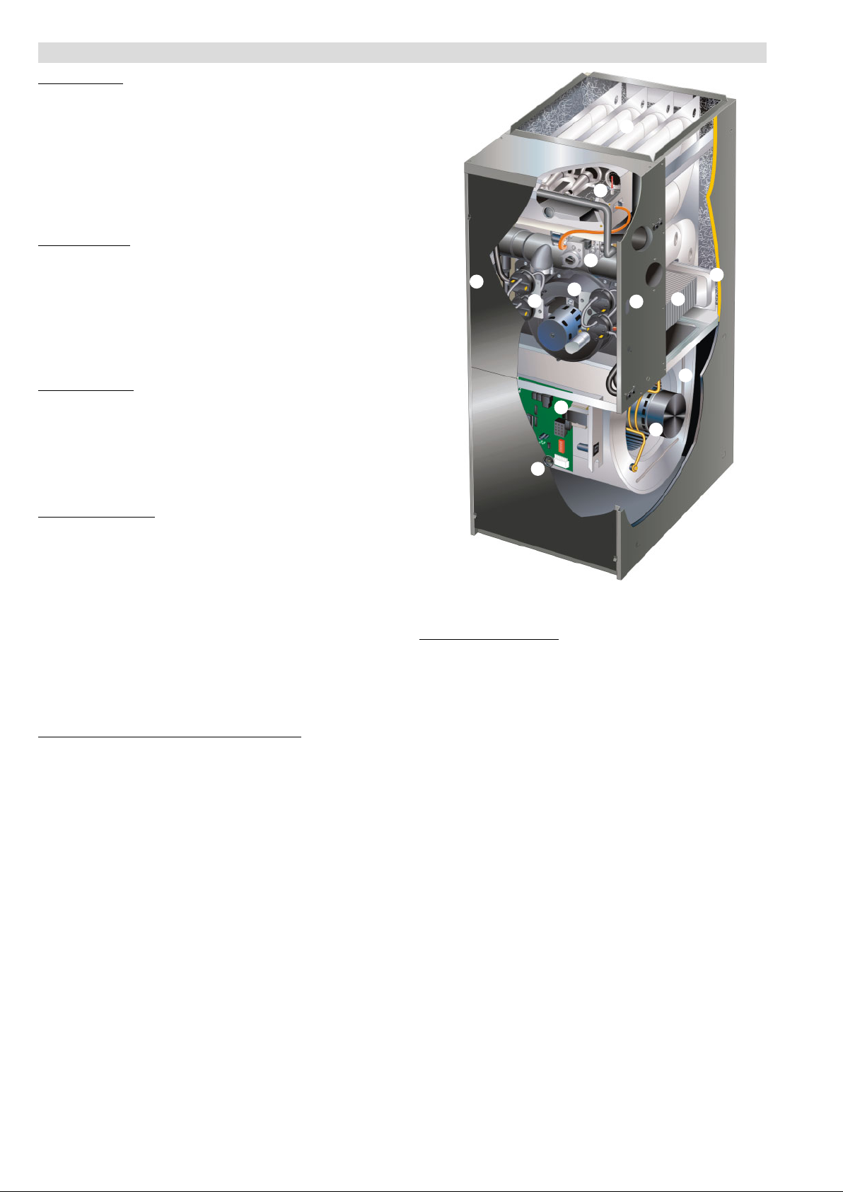
HEATING SYSTEM
Lennox Duralok Plus
B
Lennox developed heat exchanger assembly consists
of primary heat exchanger and secondary condenser
coil assembly.
Main 3-pass clamshell type heat exchanger constructed
of heavy−gauge, aluminized steel.
Designed for normal expansion and contraction.
Crimped seam design and construction provides
maximum efficiency and minimum resistance to airflow.
Secondary heat exchanger condenser coil constructed
C
of aluminum fins fitted to stainless steel tubes.
Coil is factory tested for leaks.
Condensate drain header box assembly located on
front of coil.
Compact size of complete heat exchanger assembly
permits low overall design of furnace cabinet.
All components mounted in a heavy−gauge steel frame.
Heat exchanger assembly has been laboratory life cycle
tested.
Lennox Designed Header Box
Header box on end of condenser coil collects flue
condensate for disposal through condensate collars.
Hose connects the header box drains to the condensate
collars.
The condensate collars are located on each side of the
cabinet for easy field installation of condensate drain
trap. Only one collar is used, the remainder stay
plugged.
Condensate drain trap is included with the unit for field
installation.
®
Heat Exchanger Assembly
L
G61MPVT − 50hz / Page 2
Page 3

FEATURES
HEATING SYSTEM − continued
Lennox Designed Flue Condensate Trap Assembly
Condensate trap assembly is mounted outside the
conditioned air stream.
Assembly can be mounted on either side of cabinet in
up−flow and down−flow applications. Assembly is mounted
on the bottom of the cabinet in horizontal applications. See
Installation Instructions.
Connection can be made with field provided 1/2 in. PVC
pipe, 3/4 in. PVC coupling, or 1−1/4 in. OD x 1 in. ID tubing
with hose clamp.
Easy to clean and winterize.
Inshot Burners
D
Aluminized steel inshot burners provide efficient,
trouble−free operation.
Burner venturi mixes air and gas in correct proportion for
proper combustion.
Burner assembly is removable from the unit as a single
component for ease of service.
Two−Stage Gas Control Valve
E
24 volt redundant combination two stage gas control
valve combines manual shut off valve (On−Off),
automatic electric valve (dual) and gas pressure
regulation into a compact combination control.
Flame Rollout Switch
Manual reset switches are factory installed on burner
box.
Switch provides protection from abnormal operating
conditions.
Hot Surface Mini−Nitride Ignitor
Unique, non−porous, high strength proprietary ceramic
material provides long life and trouble−free
maintenance.
Low mass element provides fast heat−up and consistent
igniter temperature with low power usage.
Cemented to alumina block for positive mounting and
protection against current leakage.
High temperature Teflon
for dependable operation.
Combustion Air Inducer
F
PSC, heavy−duty blower prepurges heat exchanger and
safely vents flue products.
Pressure switches prove blower operation before
G
allowing gas valve to open.
Operates only during heating cycle.
Limit Control
Automatic reset, primary and secondary limits are
accurately located.
Primary limit factory installed on vestibule panel on all
units, secondary limit factory installed on blower
housing.
OPTIONS
High Altitude Pressure Switch Kit
Required on certain units for proper unit operation on
installations above 610 m.
Units not approved for installations above 1372 m.
Order two per unit.
LPG/Propane Conversion Kit
Required for field changeover from natural gas to
LPG/Propane.
Natural Gas Conversion Kit
Required for field changeover from LPG/Propane to
natural gas.
®
insulated ignition lead wires
CONTROLS
Integrated Two Stage / Variable Speed Blower
H
Control
Solid−state board contains all necessary controls and
relays to operate furnace.
Combustion air inducer is controlled by board. Prior to
ignition, a pre−purge cycle for 15 seconds is initiated.
After the main burners are turned off, a post−purge cycle
for 5 seconds is run.
Electronic flame sensor assures safe, reliable
operation.
Should flame fail to ignite, flame sensor will initiate 4
re−attempts at ignition before locking out unit operation
for 60 minutes.
Watchguard type circuit automatically resets ignition
controls after one hour of continuous thermostat
demand after unit lockout, eliminating nuisance calls for
service.
To aid in troubleshooting, the last three fault codes are
stored for a maximum of six months. Displays the fault
codes through indicator LED’s.
Jumper settings for 1 or 2 stage thermostat operation.
Two selectable 2nd stage recognition times (10 and 15
minutes) are available on the board when the furnace is
used with a single stage thermostat. When used with a
two stage thermostat, furnace will only initiate second
stage operation with a second stage thermostat
demand.
Two accessory terminals furnished for additional power
I
supply requirements for 240 volt (less than 1 amp)
power humidifiers and powered air cleaners.
Two blower speeds − second stage heat and second
stage cool (with four air volume selections for each) are
selected by DIP switches on board. Heat speed can be
adjusted to optimize discharge temperature. Cool
speed can be adjusted to correct optional cooling
capacity. See Blower Performance tables.
First stage blower speed is a percentage of 2nd stage
speed.
The ADJUST switch (DIP) allows normal (NORM), 10%
higher (+ plus) or 10% lower
selection within HEAT and COOL speeds selected for
fine tuning air volume.
DELAY switch (DIP) allows one of four de−humidification
profiles during cooling mode.
Profile A − Motor runs at 50% for 30 seconds, then at
82% for 7−1/2 minutes, then at 100% (if needed) until
demand is satisfied. Once demand is met, motor runs
at 50% for 30 seconds, then ramps down to stop.
Profile B − Motor runs at 82% for 7−1/2 minutes and
then at 100% (if needed) until demand is satisfied.
Once demand is met,motor ramps down to stop.
Profile C − Motor runs at 100% until demand is
satisfied. Once demand is met, motor runs at 100% for
60 seconds, then ramps down to stop.
Profile D − Motor runs at 100% until demand is satisfied.
Once demand is met, motor ramps down to stop.
In heat mode, blower on time is fixed at 45 seconds,
blower off time is adjustable from 60, 90, 120 and 180
seconds (factory setting − 90 seconds).
Power Lead
2.5 m power lead is provided for connection to an IEC
receptacle located on the right side of the furnace.
IEC Receptacle
IEC receptacle provided on right side of furnace cabinet
for easy, plug−in electrical connection.
24 Volt Transformer
Furnished and factory installed on blower wrapper.
40VA transformer has circuit breaker wired in series.
( minus) motor speed
G61MPVT − 50hz / Page 3
Page 4

FEATURES
CONTROLS − CONTINUED
OPTIONS
SignatureStatt Home Comfort Control
Combination temperature
and humidity.
2 Heat/2
Cool
Auto−changeover
Controls humidity during
cooling operation.
Easy−to−use, menu
driven thermostat with a back−lit, dot−matrix LCD
screen.
Remote outdoor sensor (furnished) allows the
thermostat to display outdoor temperature and adjust
indoor dewpoint temperature for precision humidity
control in cooling mode.
See the SignatureStat Engineering Handbook bulletin in
the Controls section for more information.
BLOWER
Variable Speed Direct Drive Blower
J
Each blower assembly statically and dynamically
balanced.
Change in blower speed is easily accomplished by
simple DIP switch change on Integrated Furnace Two
Stage / Variable Speed Blower Control.
See Blower Performance tables.
Blower assembly easily removed for servicing
Variable Speed Blower Motor
K
Variable speed motor maintains specified air volume
from 0 though 200 Pa static range.
Motor is controlled by Integrated Furnace Two Stage /
Variable Speed Blower Control.
Motor is resiliently mounted.
FILTER (NOT FURNISHED)
Filter and provisions for external mounting must be field
provided.
CABINET
Low−profile, narrow width cabinet allows easy
installation in up−flow, down−flow or horizontal
applications.
Heavy−gauge, cold rolled steel construction.
Pre−painted cabinet finish.
Flanges provided on supply air opening for ease of
plenum connection or alignment with indoor coil.
Fully insulated cabinet with foil faced insulation on sides
L
and back of heating compartment and mat faced
insulation in blower compartment.
Tool−less latches on blower and burner doors assure
M
positive lock.
Complete service access.
Safety interlock switch automatically shuts off power to
unit when blower compartment access door is removed.
Gas piping inlets are provided in both sides of cabinet.
N
Return Air Entry:
For bottom/end return−air entry for up−flow/horizontal
applications, remove furnished bottom seal panel from
cabinet.
For side return−air entry (up−flow applications only),
corners are marked on either side of cabinet for return
air cut−outs.
On furnaces with side return air and condensate trap on
the same side of the cabinet, a field fabricated transition
is required when using an IAQ (indoor air quality)
product higher than 360 mm installed next to the unit
and serviced from the front. IAQ products higher than
508 mm require a field fabricated transition. See
dimension drawings.
NOTE − 60C and 60D size units that require air
volumes over 850 L/s must have one of the
following:
1. Single side return air with transition, to accommodate
508 x 635 x 25 mm cleanable air filter, required to
maintain proper air velocity.
2. Bottom return air.
3. Return air from both sides.
4. Bottom and
See Blower Performance Tables for additional
information.
Coil Match−up
All furnaces exactly match C33 and CX34 cased up−flow
indoor coils and CH33 horizontal indoor coils with same
letter designation in model number. No adaptor
required. Engaging holes furnished on cabinet for
alignment.
C33 uncased coils match furnaces without any
overhang but require an optional adaptor base or field
fabricated transition to match furnace opening. See C33
coil bulletin for additional information.
All furnaces exactly match CR33 cased, down−flow
indoor coils with adaptor rails, furnished with coil.
OPTIONS
Condensate Trap Alternate Location Kit
Allows condensate drain to be installed on the opposite
side of the furnace from the exhaust venting (up−flow
applications only).
Down−Flow Combustible Floor Base
Required for heating only units installed on combustible
floors.
Not required in add-on cooling applications.
See Dimension Drawing.
one side return air.
G61MPVT − 50hz / Page 4
Page 5
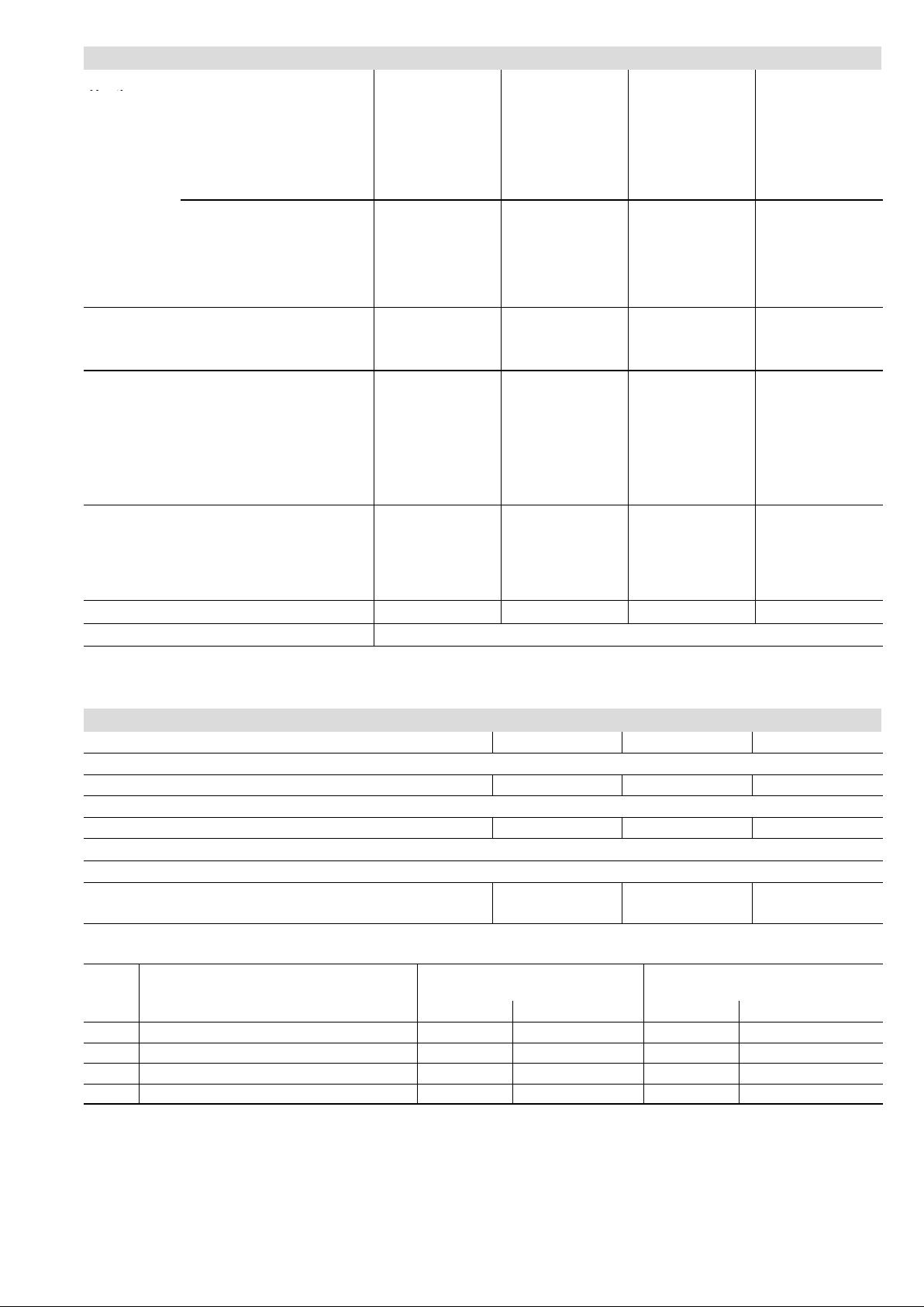
SPECIFICATIONS
Performance
Input
Gas
Heating
Connections
in.
with field supplied (PVC cplg.) − o.d. 3/4 3/4 3/4 3/4
Indoor
Blower
ShippingData kg − 1 package 68 82 85 94
Electricalcharacteristics 240 volts − 50 hertz − 1 phase (less than 10 amps)
NOTE − Filters and provisions for mounting are not furnished and must be field provided.
High
Fire
Temperature rise range − C 25 − 41 22 − 39 28 − 44 36 − 53
Gas Manifold Pressure
(Natural Gas) − Pa
Low
Fire
Temperature rise range − C 14 − 31 11 − 28 17 − 33 22 − 39
Gas Manifold Pressure
(Natural Gas) − kPa
Australian Gas Association
Energy Rating − Stars
Intake / Exhaust Pipe (PVC) 2 / 2 2 / 2 2 / 2 3 / 3
Condensate Drain Trap
hose with hose clamp − i.d. x o.d. 1−1/4 x 1 1−1/4 x 1 1−1/4 x 1 1−1/4 x 1
GaspipesizeIPS 1/2 1/2 1/2 1/2
Wheel nom. dia. x width −mm 203 x 508 292 x 508 292 x 508 292 x 508
kW ofadd−oncooling 7.0 − 12.2 12.2 − 17.6 12.2 − 17.6 12.2 − 17.6
Air Volume Range − L/s 295 − 660 410 − 1020 350 − 1045 430 − 1035
ModelNo. G61MPVT−36B−070 G61MPVT−60C−090 G61MPVT−60C−110 G61MPVT−60D−135
Input− Mj/h 69.6 92.8 116.1 139.3
Output− kW 17.9 23.7 29.0 35.7
0.87 0.87 0.87 0.87
Input− Mj/h 47.5 63.3 79.1 95.0
Output− kW 12.6 16.7 21.1 25.5
0.42 0.42 0.42 0.42
5.3 5.3 5.3 5.3
Highstatic− Pa 200 200 200 200
1/2 1/2 1/2 1/2
(PVC pipe) − i.d.
Motoroutput − W 373 745 745 745
OPTIONAL ACCESSORIES − MUST BE ORDERED EXTRA
B" Width Models C" Width Models D" Width Models
CABINET ACCESSORIES
Down−Flow Combustible Floor Base 11M60 11M61 11M62
CONDENSATE DRAIN KITS
Condensate Trap Alternate Location Kit − Up−Flow Only 76M20 76M20 − − −
CONTROLS
TERMINATION KITS − See Installation Instructions for specific venting information.
Concentric Termination Kits − Direct Vent
Applications Only
GAS HEAT ACCESSORIES
High Altitude Pressure Switch Kit
Input
−070 56M23 59M13 59M13 59M87 59M87
−090 56M23 59M13 59M13 59M87 59M87
−110 75M22 59M13 59M13 59M87 59M87
−135 Not allowed 59M13 Not allowed 59M87 Not allowed
ORDER TWO EACH
611 − 1372 m 0 − 610 m 611 − 1372 m 0 − 610 m 611−1372 m
50 mm (2 in.) 71M80 69M29 − − −
80 mm (3 in.) − − − 60L46 60L46
LPG/Propane Kit LPG/Propane to
Natural Gas Kit
G61MPVT − 50hz / Page 5
Page 6

HIGH ALTITUDE INFORMATION
Vent Pipe
G61MPVT
G61MPVT
G61MPVT
G61MPVT
G61MPVT
G61MPVT
G61MPVT
G61MPVT
Heat Size
(Di
th)
070
090
110
135
Pressure regulator adjustment will be required depending on altitude. See below for proper pressure regulator setting.
Manifold Pressure (Outlet) at High Fire − kPa
Altitude − m
Fuel
0−610
1
611−914
1
915−1219
1
1220−1372
Natural 0.87 0.80 0.75 0.70
2
LPG/Propane 2.49 2.29 2.12 2.02
1
High Altitude Pressure Switch Kits required for certain models, see Gas Heat Accessories table for order number.
2
LPG/Propane conversion kit required, see Gas Heat Accessories table for order number.
EXHAUST PIPE VENTING TABLE
For altitudes of 0−610 m
1
Maximum Equivalent Vent Length − m
Vent Pipe G61MPVT G61MPVT
Diameter
−36B−070
−60C−090
2
G61MPVT
−60C−110
50 mm (2 in.) 12.2 4.5 not allowed not allowed 7.6 not allowed not allowed not allowed
80 mm (3 in.) 16.1 12.2 12.2 7.6 10 7.6 7.6 not allowed
100 mm (4 in.) 44 34.5 30 20 27.5 21.5 18.7 not allowed
NOTE − Minimum Equivalent Vent Pipe length is 4.6 m.
1
Maximum Equivalent Vent Length" permitted is defined as Total Length (linear meters) of vent pipe, plus equivalent length (m) of fittings, plus equivalent length (m) of termination".
2
110 models installed in up−flow or down−flow applications must have the supplied 90° street ell installed directly into the unit flue collar. The street ell must be included
in the elbow count.
3
135 models installed in down−flow applications must have 80 to 50 mm (3 in. to 2 in.) reducing elbow (supplied) installed directly into the flue collar. Reducing ell must be
included in elbow count.
4
90 elbows must be limited to sweep type elbows.
VENTING NOTES One 90elbow is equivalent to 1.5 m of straight vent pipe.
Wall and roof termination (non−concentric) exhaust pipe must terminate with reducer to improve exhaust velocity away from intake piping.
Two 45 elbows are equal to one 90 elbow.
One 45 elbow is equivalent to 0.76 m of straight vent pipe.
070 − 50, 80, or 100 mm (2, 3 or 4 in.) − terminate with 40 mm (1−1/2 in.) pipe
090 − 50, 80, or 100 mm (2, 3 or 4 in.). − terminate with 50 mm (2 in.) pipe
110 − 80 or 100 mm (3 or 4 in.) − terminate with 50 mm (2 in.) pipe
135 − 80 or 100 mm (3 or 4 in.) − terminate with 50 mm (2 in.) pipe
3
G61MPVT G61MPVT G61MPVT
−60D−135
−36B−070
For altitudes of 611−1372 m
1
Maximum Equivalent Vent Length − m
−60C−090
2
G61MPVT
−60C−110
3
G61MPVT
−60D−135
TERMINATION KITS − EQUIVALENT VENT LENGTHS
Vent Pipe Equivalent Length − meters
Heat Size
Vent Pipe Di-
ameter
50 mm (2 in.) 80 mm (3 in.)
1
71M80 or 69M29 60L46 40 mm (1−1/2 in.) x 305 mm 50 mm (2 in.) x 305 mm
50 mm (2 in.) 3.6 not allowed 1.2 not allowed
−070
80 mm (3 in.)
100 mm (4 in.) 12.8 not allowed 4.3 not allowed
50 mm (2 in.) 0.9 0.9 not allowed 0.3
−090
80 mm (3 in.)
100 mm (4 in.) 3.7 3.7 not allowed 1.2
−
−
1
Outdoor exhaust accelerator included in 71M80 kit; for use with −070 models.
80 mm (3 in.) 1.8 1.8 not allowed 0.6
100 mm (4 in.) 3.7 3.7 not allowed 1.2
80 mm (3 in.) not allowed 4.6 not allowed 1.8
100 mm (4 in.) not allowed 7.6 not allowed 3.0
Concentric
Kits
7.3 not allowed 2.4 not allowed
1.8 1.8 not allowed 0.6
Outdoor Exhaust Accelerator
ameter X Leng
G61MPVT − 50hz / Page 6
Page 7

INSTALLATION CONFIGURATIONS
DOWN−FLOW
BLOWER
HEAT
EXCHANGER
AIR FLOW
VENT
PIPING
CONDENSATE
DRAIN
VENT
PIPING
CONDENSATE
DRAIN
UP−FLOW
AIR FLOW
HEAT
EXCHANGER
BLOWER
NOTE − On up−flow and down−flow configurations, the vent piping and
condensate drain can be moved to the other side of the unit. Vent piping
and drain must be installed on the same side of the unit with each other
unless optional Condensate Trap Alternate Location Kit (up−flow only) is
used. On horizontal installations the drain must be located at the bottom
and the vent piping at the top.
AIR
FLOW
HORIZONTAL − RIGHT
BLOWER
HORIZONTAL − LEFT
VENT
PIPING
HEAT
EXCHANGER
CONDENSATE
DRAIN
VENT
PIPING
HEAT
EXCHANGER
CONDENSATE
DRAIN
BLOWER
AIR
FLOW
FILTER AIR RESISTANCE
For 25 mm Cleanable Filter (Field Provided)
L/s Pa
0 0
95 2
190 7
285 10
375 15
470 22
565 30
660 37
755 47
850 57
945 67
1040 82
1130 94
1225 109
INSTALLATION CLEARANCES
Sides
Rear 0 mm
Top/Plenum 25 mm
Front 0 mm
Front (service/alcove) 610 mm
Floor
1
Allow proper clearances to accommodate condensate trap and vent pipe
installation.
2
Clearance for installation on combustible floor if optional down−flow combustible
floor base is installed between furnace and combustible floor. Not required in
add-on cooling applications if installed in accordance with local codes Do not install
the furnace directly on carpeting, tile, or other combustible materials other than
wood flooring.
1
0 mm
2
Combustible
G61MPVT − 50hz / Page 7
Page 8

DIMENSIONS − MM − UP−FLOW POSITION SHOWN
1
NOTE − 60C and 60D size units that require air volumes over 850
L/s must have one of the following:
a. Single side return air with transition, to accommodate
508 x 635 x 25 mm air filter. Required to maintain proper air velocity.
b. Bottom return air.
c. Return air from both sides.
d. Bottom and
See Blower Performance Tables for additional information.
one side return air.
SUPPLY AIR
OPENING
TOP VIEW
A
B
AIR FLOW
14
1016
295 Right
248 Left
165
103
124 Right
57 Left
476
IEC
Receptacle
140
171
165
79
64
102
RETURN CUTOUT
724
494
COMBUSTION AIR INTAKE
(Either Side)
EXHAUST AIR OUTLET
(Either Side)
GAS PIPING INLET
(Either Side)
CONDENSATE
TRAP CONNECTION
(Either Side)
ELECTRICAL INLET
(Either Side)
584
1
OPTIONAL
(Either Side)
Up−Flow Only
356
49
14
19
C
1
Bottom Return
Air Opening
FRONT VIEW SIDE VIEW
Model No. A B C
G61MPVT−36B−070 446 416 406
G61MPVT−60C−090
G61MPVT−60C−110
G61MPVT−60D−135 622 594 584
G61MPVT − 50hz / Page 8
19
597
108
1
Bottom Return
Air Opening
533 505 495
Page 9

DIMENSIONS − mm − FURNACE/COIL COMBINED DIMENSIONS
UP−FLOW POSITION
DOWN−FLOW POSITION
Furnace
Width
A
1016
UP−FLOW POSITION
Uncased
Model No
CX34−18/24B−6F
CX34−18/24C−6F
CX34−25B−6F C33−25B 495 1511 403 1419
CX34−30B−6F
B
CX34−30C−6F
CX34−31B−6F C33−31B 597 1613 514 1530
CX34−36B−6F C33−36B 622 1638 556 1572
CX34−36C−6F C33−36C 622 1638 540 1556
CX34−38B−6F C33−38B 622 1638 559 1575
CX34−42B−6F C33−42B 622 1638 556 1572
CX34−43B−6F C33−43B 724 1740 667 1683
CX34−43C−6F C33−43C 724 1740 654 1670
CX34−44/48B−6F C33−48B 622 1638 562 1578
CX34−44/48C−6F C33−48C 622 1638 546 1562
CX34−49C−6F C33−49C 749 1765 724 1740
CX34−50/60C−6F C33−50/60C 699 1715 629 1645
CX34−60D−6F C33−60D 648 1664 629 1645
CX34−62C−6F C33−62C 749 1765 778 1793
CX34−62D−6F C33−62D 749 1765 730 1746
C33−24B
C33−24C
C33−30B
C33−30C
C33−44C 622 1638 546 1562
Cased
A B A B
419 1435 352 1368
521 1537 451 1467
(CX34 − cased
only)
Coil
Width
HORIZONTAL
A
1016
Overall
Height
Coil
Height
B
1016
DOWN−FLOW POSITION
Model
Number
CR33-24B−F
CR33-30/36B−F 446 446 410 1426
CR33-30/36C−F 533 533 410 1426
CR33-48B−F
CR33-48C−F
CR33-50/60C−F 622 533 600 1362
CR33-60D−F 622 622 600 1362
HORIZONTAL POSITION
CH33−36B−2F
CH33−36C−2F
CH33−44/48B−2F
CH33−50/60C−2F
Coil Width
446 446 337 1353
533 446 508 1524
533 533 508 1524
Model
Number
CH33−42B−2F
CH33−48C−2F
CH33−60D−2F
CH33−62D−2F
Furnace
Width
Coil Height
A B
673 1689
800 1816
Overall
Height
G61MPVT − 50hz / Page 9
Page 10

OPTIONAL ACCESSORY DIMENSIONS − MM
DOWN-FLOW COMBUSTIBLE FLOOR BASE
SUPPLY
OPENING
DOWN
FLOW
FURNACE
38
Front Of Furnace
AIR
38
503
692
21-13/16
B
38
(1-1/2)
A
38
559
C
DOWN-FLOW
COMBUSTIBLE
FLOOR BASE
FLOOR
OPENING
TOP VIEW
SIDE VIEW
Model No. A B C
G61MPVT−36B−070 497 421 476
G61MPVT−60C−090
G61MPVT−60C−110
586 510 565
G61MPVT−60D−135 675 598 654
G61MPVT − 50hz / Page 10
Page 11

OPTIONAL ACCESSORY DIMENSIONS − MM
CONCENTRIC WALL
TERMINATION APPLICATIONS
OUTSIDE
EXHAUST
AIR
INTAKE
AIR
WALL
CLAMP
(Not Furnished)
See Installation Instructions for specific usage.
INTAKE
AIR
EXHAUST
AIR
INTAKE
AIR
GRADE
305
Minimum
Above
Grade
71M80/69M29 − 2 inch
60L46 3 inch
CONCENTRIC ROOF
TERMINATION APPLICATIONS
305
Minimum
Above Average
Snow
Accumulation
CLAMP
FLASHING
(Not Furnished)
SHEET METAL STRAP
(Clamp and sheet metal strap
must be field installed to support
the weight of the termination kit.)
ELBOW
(Field Supplied)
848 − 71M80/69M29
987 − 60L46
89 − 71M80/69M29
114 − 60L46
INTAKE AIR
TERMINATION
ASSEMBLY
(Furnished)
165
152
EXHAUST
AIR
Outdoor Exhaust Accelerator
included with 71M80
(Required with −070 models)
G61MPVT − 50hz / Page 11
Page 12

BLOWER DATA − 0 through 200 Pa External Static Pressure Range
ADJUST"
Stc
ADJUST"
Stc
ADJUST"
Stc
ADJUST"
Stc
G61MPVT−36B−070 BLOWER PERFORMANCE (less filter)
Switch
Positions
"
Second Stage HEAT" Speed − L/s Second Stage COOL" Speed − L/s
1
1
2 3 4 1 2 3
+ 420 485 610 630 480 560 605 660
1
NORM 385 445 545 570 440 500 545 600
N/A 395 480 495 390 450 475 520
ADJUST"
Switch
Positions
First Stage HEAT" Speed − L/s First Stage COOL" Speed − L/s
1
1
2 3 4 1 2 3
+ 385 440 545 570 345 385 410 440
1
NORM 360 410 495 515 320 355 375 405
N/A 365 440 455 295 330 345 365
G61MPVT−60C−090 BLOWER PERFORMANCE (less filter)
Bottom Return Air, Return Air from Both Sides or Return Air from Bottom and One Side.
Switch
Positions
"
Second Stage HEAT" Speed − L/s Second Stage COOL" Speed − L/s
1
1
2 3 4 1 2 3
+ 710 790 885 985 755 805 910 1020
1
NORM 640 730 810 895 680 735 830 925
565 645 725 800 600 650 750 830
ADJUST"
Switch
Positions
First Stage HEAT" Speed − L/s First Stage COOL" Speed − L/s
1
1
2 3 4 1 2 3
+ 640 735 815 900 520 560 640 730
1
NORM 575 665 750 820 470 510 570 635
520 580 665 740 420 455 515 575
Speed Switch Positions
Speed Switch Positions
1
4
1
4
1
4
1
4
G61MPVT−60C−090 BLOWER PERFORMANCE (less filter)
Single Side Return Air − Air volumes in bold require field fabricated transition to accommodate 508 x 635 x 25 mm cleanable
air filter in order to maintain proper air velocity across the filter.
Switch
Positions
"
Second Stage HEAT" Speed − L/s Second Stage COOL" Speed − L/s
1
1
2 3 4 1 2 3
Speed Switch Positions
1
+ 685 775 860 970 745 800 895 1010
1
NORM 625 710 800 885 665 722 820 915
550 625 710 785 590 640 735 820
ADJUST"
Switch
Positions
First Stage HEAT" Speed − L/s First Stage COOL" Speed − L/s
1
1
2 3 4 1 2 3
1
+ 620 710 800 885 510 545 620 705
1
NORM 560 645 730 810 465 500 560 630
505 570 645 715 410 440 500 560
G61MPVT−60C−110 BLOWER PERFORMANCE (less filter)
Bottom Return Air, Return Air from Both Sides or Return Air from Bottom and One Side.
Switch
Positions
"
Second Stage HEAT" Speed − L/s Second Stage COOL" Speed − L/s
1
1
2 3 4 1 2 3
Speed Switch Positions
1
+ 710 805 905 1005 765 825 940 1045
1
NORM 645 740 830 915 690 745 845 940
570 650 740 820 610 665 755 845
ADJUST"
Switch
Positions
First Stage HEAT" Speed − L/s First Stage COOL" Speed − L/s
1
1
2 3 4 1 2 3
1
+ 645 740 830 920 445 480 545 615
1
NORM 580 670 755 840 395 430 495 555
520 590 670 745 350 375 434 495
1
Factory default jumper setting.
N/A − First and second stage HEAT positions shown cannot be used on this model.
NOTES − The effect of static pressure is included in air volumes shown.
First stage HEAT is approximately 91% of the same second stage
First stage COOL (two−stage air conditioning units only) is approximately 70% of the same second stage COOL speed position.
Continuous Fan Only speed is approximately 38% of the same second stage COOL speed position − minimum 235 L/s.
HEAT speed position.
4
4
4
4
G61MPVT − 50hz / Page 12
Page 13

BLOWER DATA − 0 through 200 Pa External Static Pressure Range
ADJUST"
Stc
ADJUST"
Stc
G61MPVT−60C−110 BLOWER PERFORMANCE (less filter)
Single Side Return Air − Air volumes in bold require field fabricated transition to accommodate 508 x 635 x 25 mm cleanable
air filter in order to maintain proper air velocity across the filter.
Switch
Positions
"
Second Stage HEAT" Speed − L/s Second Stage COOL" Speed − L/s
1
1
2 3 4 1 2 3
+ 700 790 880 980 750 800 900 1010
1
NORM 635 720 815 895 675 725 820 910
555 630 710 790 605 655 740 830
ADJUST"
Switch
Positions
First Stage HEAT" Speed − L/s First Stage COOL" Speed − L/s
1
1
2 3 4 1 2 3
+ 625 710 800 880 440 485 545 605
1
NORM 565 645 730 810 395 430 495 555
510 570 645 720 355 375 435 495
G61MPVT−60D−135 BLOWER PERFORMANCE (less filter)
Bottom Return Air, Return Air from Both Sides or Return Air from Bottom and One Side.
Switch
Positions
"
Second Stage HEAT" Speed − L/s Second Stage COOL" Speed − L/s
1
1
2 3 4 1 2 3
+ 710 805 895 995 760 815 915 1035
1
NORM 645 730 820 905 685 745 840 935
580 650 730 810 615 660 755 840
ADJUST"
Switch
Positions
First Stage HEAT" Speed − L/s First Stage COOL" Speed − L/s
1
1
2 3 4 1 2 3
+ 655 740 830 910 535 570 645 725
1
NORM 590 670 750 835 485 520 580 655
535 595 675 750 430 465 525 580
1
Factory default jumper setting.
N/A − First and second stage HEAT positions shown cannot be used on this model.
NOTES − The effect of static pressure is included in air volumes shown.
First stage HEAT is approximately 91% of the same second stage
First stage COOL (two−stage air conditioning units only) is approximately 70% of the same second stage COOL speed position.
Continuous Fan Only speed is approximately 38% of the same second stage COOL speed position − minimum 235 L/s.
HEAT speed position.
Speed Switch Positions
1
1
Speed Switch Positions
1
1
4
4
4
4
G61MPVT − 50hz / Page 13
Page 14

Page 15

Page 16

Visit us at www.lennox.com
For the latest technical information, www.lennoxdavenet.com
NOTE − Due to Lennox’ ongoing committment to quality, Specifications, Ratings and Dimensions subject to change without notice and without incurring liability.
Improper installation, adjustment, alteration, service or maintenance can cause property damage or personal injury.
Installation and service must be performed by a qualified installer and servicing agency.
©2006 Lennox Heating and Air Conditioning − Division of Heatcraft Australia Pty, LTD
 Loading...