

Lennox G61MPV−36C−090, G61MPV−36B−045, G61MPV−36B−070, G61MPV−36B−071, G61MPV−60C−090 Service Manual
...Page 1
Corp. 0310−L7
Service Literature
Revised 03−2008
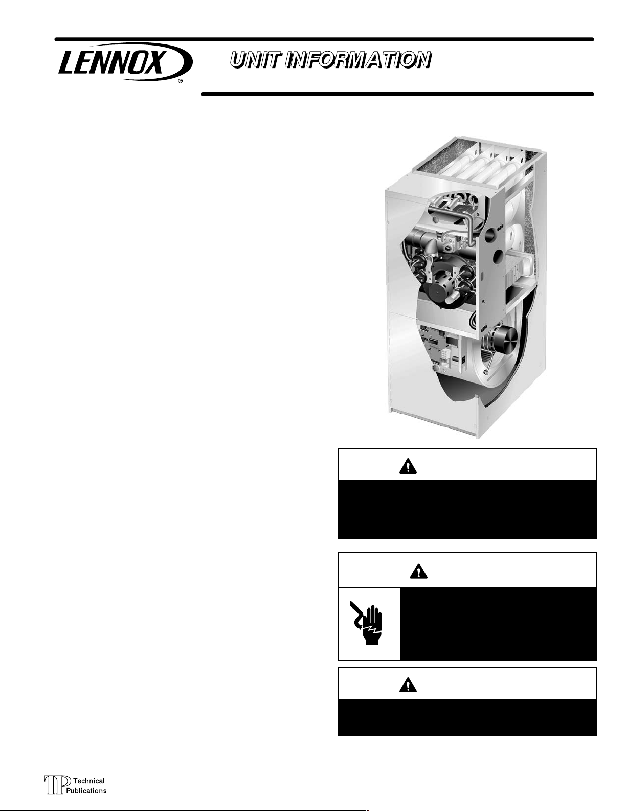
G61MPV SERIES UNITS
G61MPV series units are high−efficiency multi−position
(upflow, downflow, horizontal right and left) gas furnaces
manufactured with Lennox Duralok Plust heat exchang-
ers formed of an aluminized steel primary with a stainless
steel secondary condensing coil. G61MPV units are available in heating capacities of 44,000 to 132,000 Btuh
(13.0.0 to 38.6 kW) and cooling applications from 2 to 5
tons (7.0 kW to 17.5 kW). Refer to Engineering Handbook
for proper sizing.
Units are factory equipped for use with natural gas. Kits are
available for conversion to LPG operation. G61MPV model
units are equipped with the two−stage variable speed integrated SureLight® control. All G61MPV units meet the California Nitrogen Oxides (NO
sonal Efficiency requirements. All units use a redundant gas
valve to assure safety shut−off as required by C.S.A.
) Standards and California Sea-
x
G61MPV
All specifications in this manual are subject to change. Procedures outlined in this manual are presented as a recommendation only and do not supersede or replace local or
state codes. In the absence of local or state codes, the
guidelines and procedures outlined in this manual (except
where noted) are recommendations only and do not constitute code.
TABLE OF CONTENTS
Specifications Page 2. . . . . . . . . . . . . . . . . . . . . . . . . . . . .
Blower Data Page 4. . . . . . . . . . . . . . . . . . . . . . . . . . . . . .
Parts Identification Page 23. . . . . . . . . . . . . . . . . . . . . . . .
I Unit Components Page 24. . . . . . . . . . . . . . . . . . . . . . .
II Installation Page 47. . . . . . . . . . . . . . . . . . . . . . . . . . . .
III Start Up Page 61. . . . . . . . . . . . . . . . . . . . . . . . . . . . . . .
IV Heating System Service Checks Page 62. . . . . . . . .
V Typical Operating Characteristics Page 67. . . . . . . . .
VI Maintenance Page 68. . . . . . . . . . . . . . . . . . . . . . . . . .
VII Wiring and Sequence of Operation Page 71. . . . . .
VIII Field Wiring and Jumper Setting Page 86. . . . . . . .
IX Control Board Troubleshooting Page 91. . . . . . . . . .
IMPORTANT
Improper installation, adjustment, alteration, service
or maintenance can cause property damage, personal injury or loss of life. Installation and service must
be performed by a qualified installer, service agency
or the gas supplier.
WARNING
Electric shock hazard. Can cause injury
or death. Before attempting to perform
any service or maintenance, turn the
electrical power to unit OFF at disconnect switch(es). Unit may have multiple
power supplies.
WARNING
Sharp edges.
Be careful when servicing unit to avoid sharp edges
which may result in personal injury.
Page 1
© 2003 Lennox Industries Inc.
Page 2
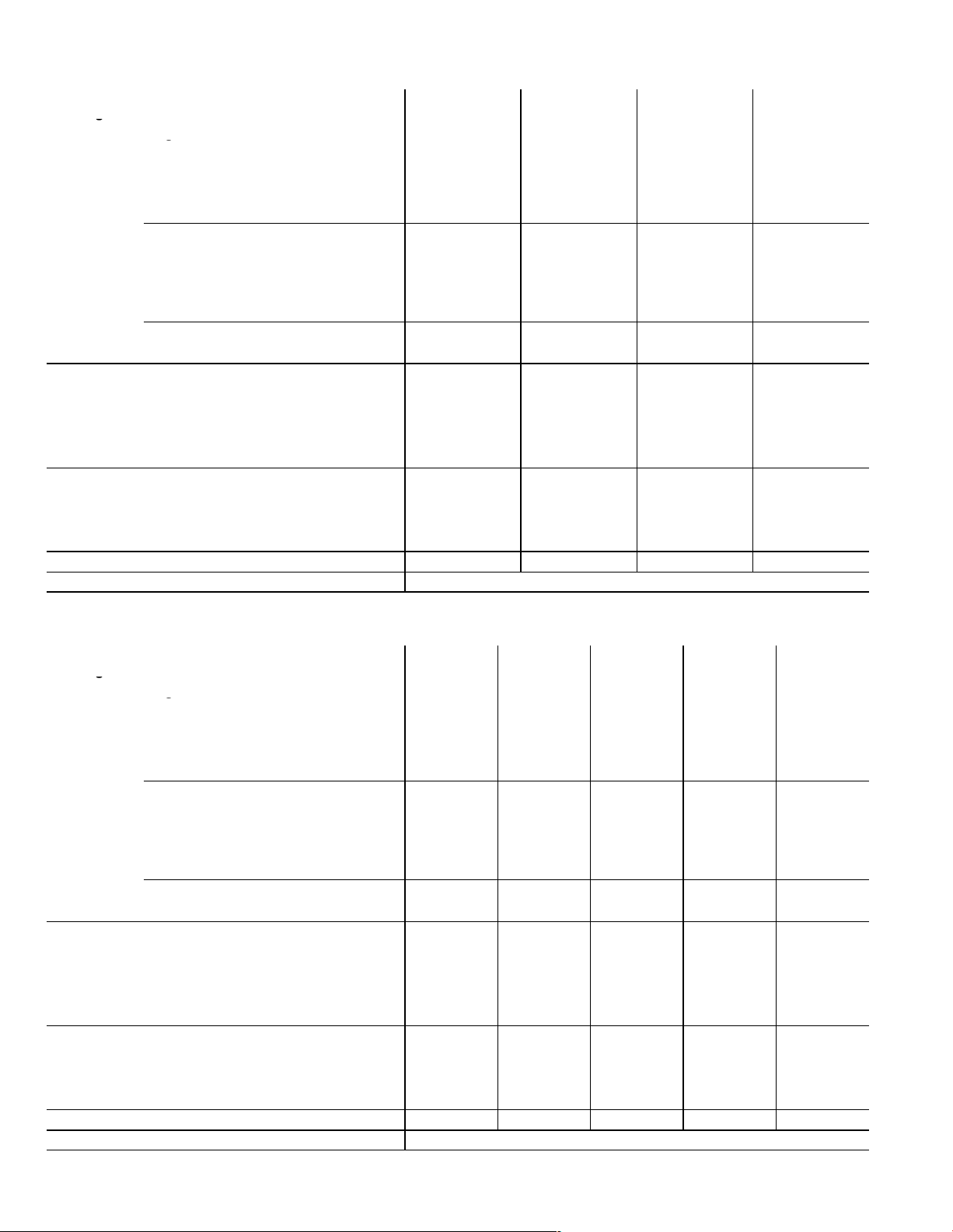
SPECIFICATIONS
g
g
g
g
Gas
Heating
Performance
High Fire
ModelNo. G61MPV
−36B−045
Input− Btuh
44,000 66,000 66,000 88,000
G61MPV
−36B−070
G61MPV
−36B−071
G61MPV
−36C−090
Output− Btuh 39,000 61,000 62,000 79,000
Temperature rise range − _F 20 − 50 45 − 75 45 − 75 70 − 100
Gas Manifold Pressure (in. w.g.)
3.5 / 10.0 3.5 / 10.0 3.5 / 10.0 3.5 / 10.0
Natural Gas / LPG/Propane
Low Fire
Input − Btuh 30,000 45,000 45,000 60,000
Output − Btuh 29,000 43,000 43,000 56,000
Temperature rise range − _F 10 − 40 25 − 55 20 − 50 35 − 65
Gas Manifold Pressure (in. w.g.)
1.7 / 4.9 1.7 / 4.9 1.7 / 4.9 1.7 / 4.9
Natural Gas / LPG/Propane
1
AFUE 94.1% 94.1% 95.0% 94.3%
Highstatic(CSA)− in.w.g. .80 .80 .80 .80
Connections
in.
Condensate Drain Trap (PVC pipe) − i.d.
Intake / Exhaust Pipe (PVC) 2 / 2 2 / 2 2 / 2 2 / 2
1/2 1/2 1/2 1/2
with field supplied (PVC coupling) − o.d. 3/4 3/4 3/4 3/4
hose with hose clamp − i.d. x o.d. 1−1/4 x 1 1−1/4 x 1 1−1/4 x 1 1−1/4 x 1
GaspipesizeIPS 1/2 1/2 1/2 1/2
Indoor
Blower
Wheelnominaldiameter xwidth −in. 10 x 8 10 x 8 10 x 8 10 x 10
Motoroutput − hp
1/2 1/2 1/2 1/2
Tons(kW) ofadd−oncooling 2 − 3 2 − 3.5 2 − 3.5 2 − 3.5
Air volume range − cfm
610 − 1420 625 − 1395 625 − 1395 600 − 1395
ShippingData lbs. − 1 package 128 151 151 170
Electricalcharacteristics 120 volts − 60 hertz − 1 phase (less than 12 amps)
NOTE − Filters and provisions for mounting are not furnished and must be field provided.
1
Annual Fuel Utilization Efficiency based on DOE test procedures and according to FTC labeling regulations. Isolated combustion system rating for non−weatherized furnaces.
Gas
Heating
Performance
High Fire
ModelNo. G61MPV
−60C−090
Input− Btuh 88,000
G61MPV
−60C−091
G61MPV
−60C−110
G61MPV
−60C−111
G61MPV
−60D−135
88,000 110,000 110,000 132,000
Output− Btuh 81,000 84,000 99,000 103,000 122,000
Temperature rise range − _F 40 − 70 40 − 70 50 − 80 50 − 80 65 − 95
Gas Manifold Pressure (in. w.g.)
3.5 / 10.0 3.5 / 10.0 3.5 / 10.0 3.5 / 10.0 3.5 / 10.0
Natural Gas / LPG/Propane
Low Fire
Input− Btuh 60,000 60,000 75,000 75,000 90,000
Output− Btuh 57,000 58,000 72,000 72,000 87,000
Temperature rise range − _F 20 − 50 20 − 50 30 − 60 25 − 55 40 − 70
Gas Manifold Pressure (in. w.g.)
1.7 / 4.9 1.7 / 4.9 1.7 / 4.9 1.7 / 4.9 1.7 / 4.9
Natural Gas / LPG/Propane
1
AFUE 94.6% 95.0% 94.3% 95.0% 94.6%
Highstatic(CSA)− in.w.g. .80 .80 .80 .80 .80
Connections
in.
Condensate Drain Trap (PVC pipe) − i.d. 1/2
Intake / Exhaust Pipe (PVC) 2 / 2 2 / 2 2 / 2 2 / 2 3 / 3
1/2 1/2 1/2 1/2
with field supplied (PVC coupling) − o.d. 3/4 3/4 3/4 3/4 3/4
hose with hose clamp − i.d. x o.d. 1−1/4 x 1 1−1/4 x 1 1−1/4 x 1 1−1/4 x 1 1−1/4 x 1
GaspipesizeIPS 1/2 1/2 1/2 1/2 1/2
Indoor
Blower
Wheelnominaldiameter xwidth −in. 11−1/2 x 10 11−1/2 x 10 11−1/2 x 10 11−1/2 x 10 11−1/2 x 10
Motoroutput − hp 1
1 1 1 1
Tons(kW) ofadd−oncooling 3.5 − 5 3.5 − 5 3.5 − 5 3.5 − 5 3.5 − 5
Air volume range − cfm 895 − 2215 895 − 2215 740 − 2210 740 − 2210 915 − 2190
ShippingData lbs. − 1 package 180 180 188 188 207
Electricalcharacteristics 120 volts − 60 hertz − 1 phase (less than 12 amps)
NOTE − Filters and provisions for mounting are not furnished and must be field provided.
1
Annual Fuel Utilization Efficiency based on DOE test procedures and according to FTC labeling regulations. Isolated combustion system rating for non−weatherized furnaces.
Page 2
Page 3
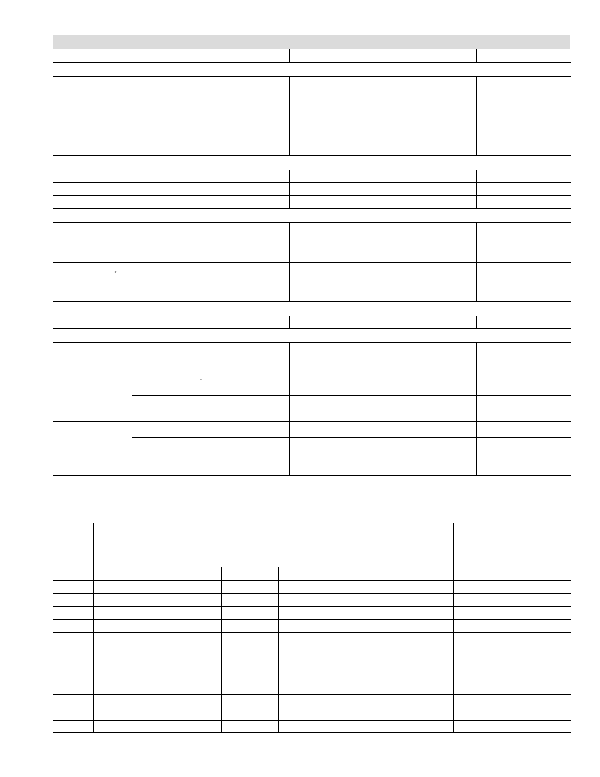
OPTIONAL ACCESSORIES − MUST BE ORDERED EXTRA
p
Di
t
Applications
p
Kit
B" Width Models C" Width Models D" Width Models
FILTER KITS
1
Air Filter and
Rack Kit
EZ Filter Base
Horizontal (end) Size of filter − in. 87L96 − 18 x 25 x 1 87L97 − 20 x 25 x 1 87L98 − 25 x 25 x 1
Side Return
Single 44J22 44J22 44J22
Ten Pack 66K63 66K63 66K63
Size of filter − in. 16 x 25 x 1 16 x 25 x 1 16 x 25 x 1
Catalog No. − Ship. Wt. − lbs. 73P56 − 7 73P57 − 8 73P58 − 10
Size of field provided filter − in. 16 x 25 x 1 20 x 25 x 1 24 x 24 x 1
CABINET ACCESSORIES
Down−Flow Additive Base 11M60 11M61 11M62
Horizontal Support Frame Kit 56J18 56J18 56J18
Return Air Base 98M60 98M58 98M59
CONDENSATE DRAIN KITS
Condensate Drain Heat Cable
Heat Cable Tape
Fiberglass − 1/2 in. x 66 ft. 39G04 39G04 39G04
Aluminum foil − 2 in. x 60 ft. 39G03 39G03 39G03
Condensate Trap Alternate Location Kit − Up−Flow Only 76M20 76M20 76M20
6 ft. 26K68 26K68 26K68
24 ft. 26K69 26K69 26K69
50 ft. 26K70 26K70 26K70
CONTROLS
SignatureStatt Home Comfort Control 81M27 81M27 81M27
TERMINATION KITS − See Installation Instructions for specific venting information.
2
Termination
Concentric
Kits
rect Ven
Applications
Wall − Close Couple
Only
Close Couple WTK 2 in. 30G28 − − − − − −
2
Termination
s − Direct or
Non−Direct Vent
2
Roof Termination Flashing Kit − Direct or Non−Direct
Roof 2 in. 15F75 15F75
Wall − Wall Ring Kit 2 in. 15F74 15F74
Vent − Contains two flashings.
1
Cleanable polyurethane frame type filter.
2
Kits contain enough parts for two, non−direct vent installations.
3
Non−direct vent only.
2 in. 71M80 69M29 − − −
3 in. − − − 60L46 60L46
2 in. 22G44 − − − − − −
3 in. 44J40 44J40 44J40
3 in. 81J20 81J20 81J20
− − −
3
15F74
44J41 44J41 44J41
GAS HEAT ACCESSORIES
High Altitude
Orifice Kit
Input
Natural Gas
Only
7501−10,000 ft. 2001−4500 ft. 4501−7500 ft. 7501−10,000 ft. 0−7500 ft. 7501−10,000 ft. 0−7500 ft.
−045 59M17 − − − − − − − − − 59M13 59M14 59M87 59M87
−070 59M17 − − − − − − 56M23 59M13 59M14 59M87 59M87
−071 59M17 75M22 75M22 56M21 59M13 59M14 59M87 59M87
−090 59M17 − − − 75M22 56M21 59M13 59M14 59M87 59M87
−090
(036C−9
and
later
models)
59M17 − − − 24W51 24W49 59M13 59M14 59M87 59M87
−091 47M82 26W85 26W85 26W86 59M13 59M14 59M87 59M87
−110 59M17 − − − 56M23 75M22 59M13 59M14 59M87 59M87
−111 47M82 56M22 56M22 56M23 59M13 59M14 59M87 59M87
−135 59M17 − − − 56M93 56M93 59M13 59M14 59M87 59M87
1
High Altitude Orifice Kit is required and must be ordered separately for applications from 7501 to 10,000 ft.
High Altitude Pressure Switch Kit
ORDER TWO EACH
Page 3
LPG/Propane Kit
LPG/Propane to
Natural Gas Kit
1
7501−10,000 ft.
Page 4
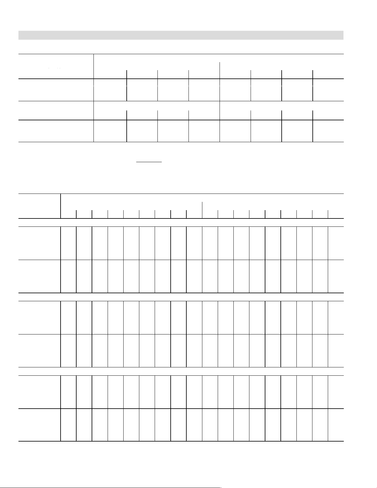
BLOWER DATA
ADJUST"
Stc
Positions
BLOWER DATA
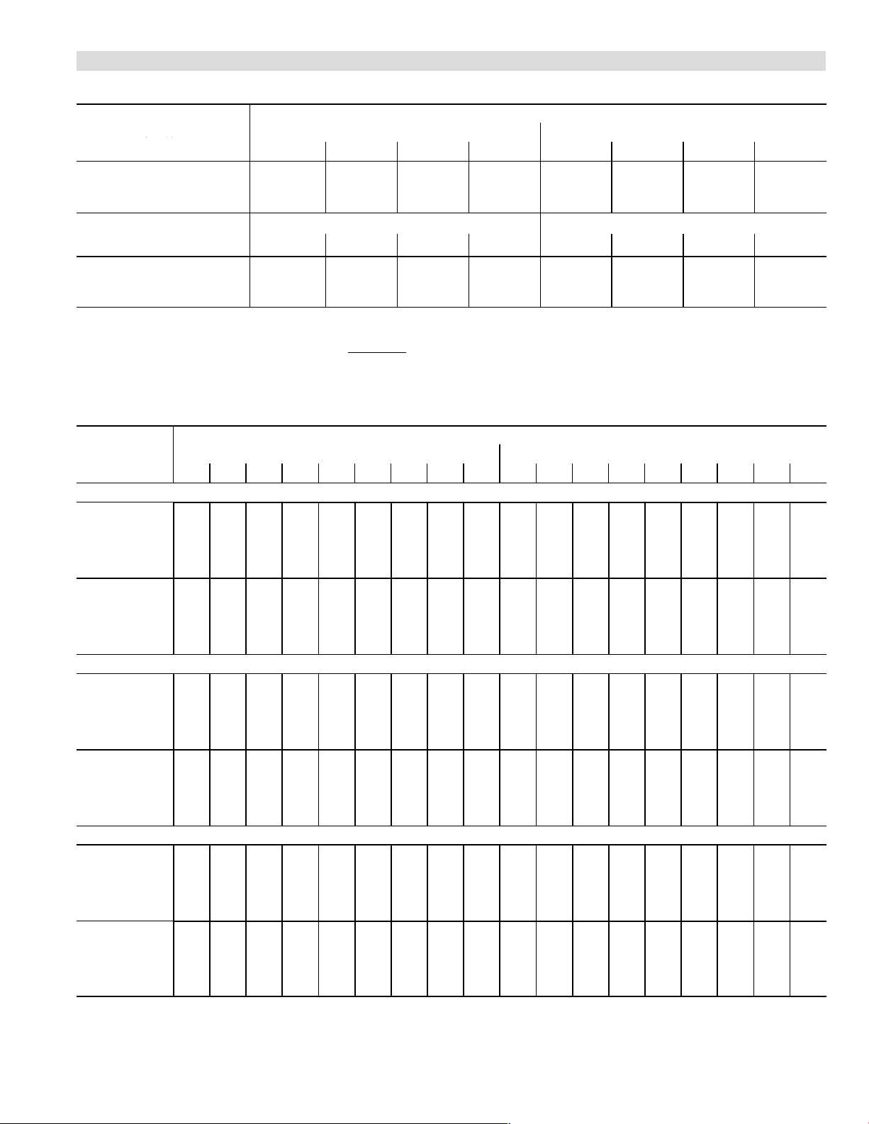
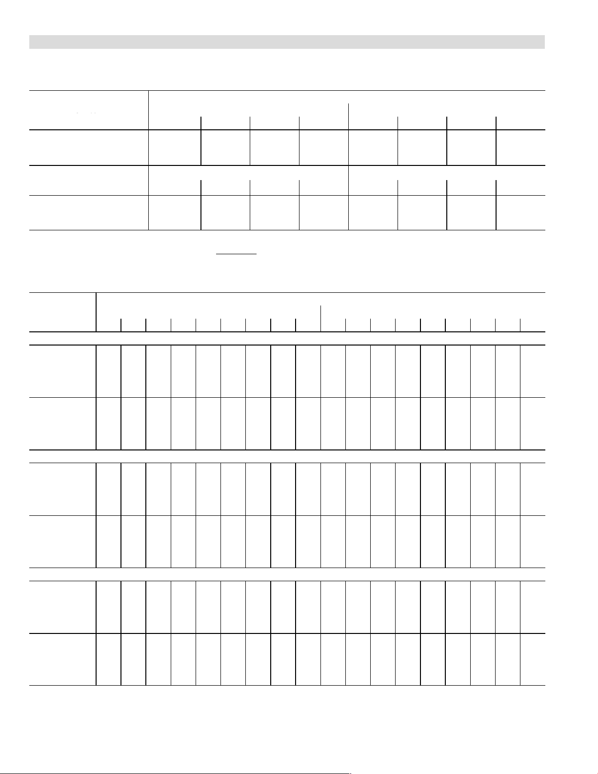
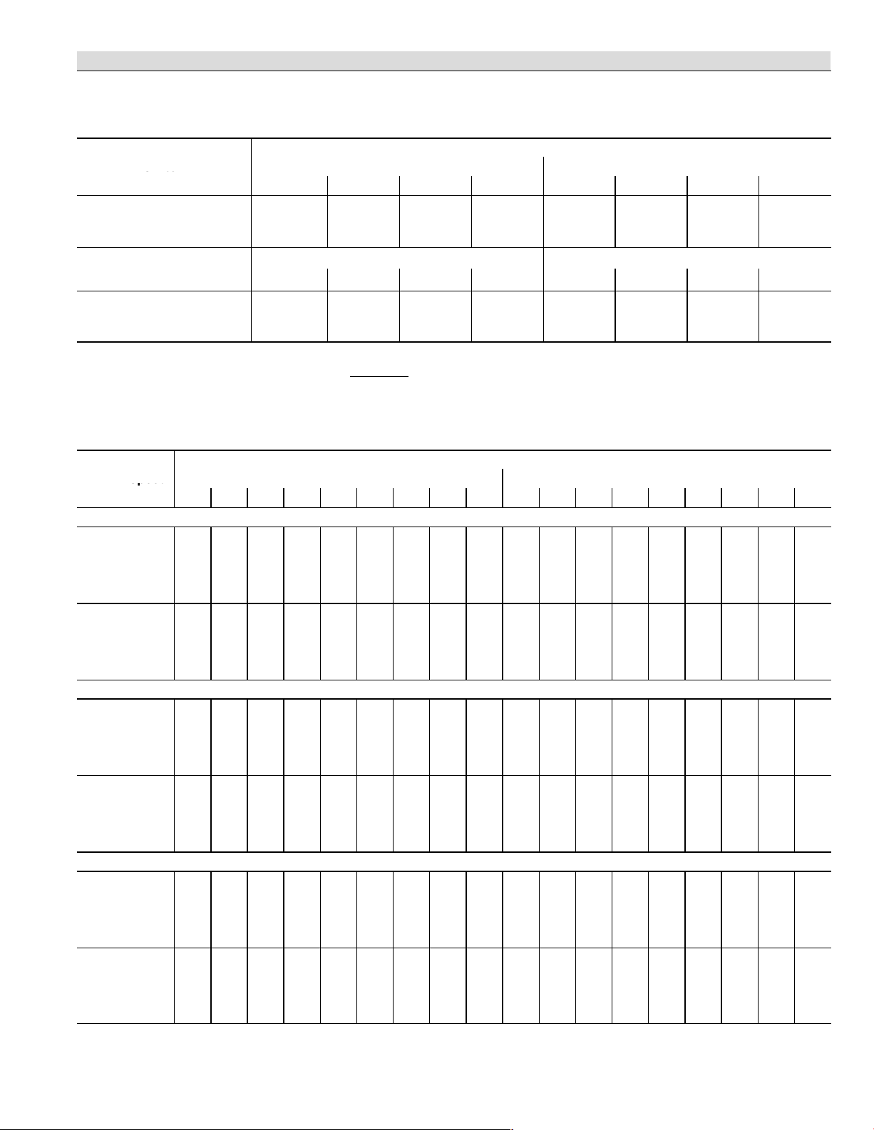
G61MPV−36B−045 BLOWER PERFORMANCE (less filter)
0 through 0.80 in. w.g. External Static Pressure Range
Switch
Positions
1
ADJUST"
Switch
Positions
1
1
Factory default jumper setting.
N/A − First and second stage HEAT positions shown cannot be used on this model.
NOTES − The effect of static pressure is included in air volumes shown.
First stage HEAT is approximately 91% of the same second stage
First stage COOL (two−stage air conditioning units only) is approximately 70% of the same second stage COOL speed position.
Continuous Fan Only speed is approximately 38% of the same second stage COOL speed position − minimum 500 cfm.
Lennox Harmony IIIt Zone Control Applications − Minimum blower speed is 442 cfm.
G61MPV−36B−045 BLOWER MOTOR WATTS
Jumper Speed
+" (Plus) SETTING (Adjust" Jumper at +" Setting)
HEAT"
Speed
Tap 1
Tap 2
Tap 3
Tap 4
COOL"
Speed
Tap 1
Tap 2
Tap 3
Tap 4
NORM" (Normal) SETTING (Adjust" Jumper at NORM" Setting)
HEAT"
Speed
Tap 1
Tap 2
Tap 3
Tap 4
COOL"
Speed
Tap 1
Tap 2
Tap 3
Tap 4
−" (Minus) SETTING (Adjust" Jumper at −" Setting)
HEAT"
Speed
Tap 1
Tap 2
Tap 3
Tap 4
COOL"
Speed
Tap 1
Tap 2
Tap 3
Tap 4
"
Second Stage HEAT" Speed − cfm Second Stage COOL" Speed − cfm
1
1
2 3 4 1 2 3
+ 915 1070 1320 1370 1055 1235 1330 1420
NORM 830 965 1205 1255 945 1100 1185 1295
740 860 1055 1095 840 970 1050 1150
First Stage HEAT" Speed − cfm First Stage COOL" Speed − cfm
1
1
2 3 4 1 2 3
+ 830 970 1210 1255 720 820 890 970
NORM 755 880 1080 1120 665 745 795 875
690 795 950 995 610 685 725 785
HEAT speed position.
Motor Watts @ Various External Static Pressures − in. wg.
First Stage Second Stage
0 0.1 0.2 0.3 0.4 0.5 0.6 0.7 0.8 0 0.1 0.2 0.3 0.4 0.5 0.6 0.7 0.8
70 90 11 5 135 155 175 200 220 245 95 120 145 175 190 210 230 255 280
125
145 165 185 205 225 255 280 305 155 175 200 225 255 290 310 335 360
220 250 280 310 340 365 390 415 440 305 335 370 400 435 465 480 495 510
225 260 300 345 375 410 430 450 470 330 360 395 430 460 485 510 530 550
55 70 90 110 125 140 160 175 195 140 165 200 230 255 280 305 325 350
90 11 0 130 155 175 200 220 240 230 260 295 330 360 390 415 435 460
70
90
110 135 160 185 205 225 245 265 280 315 350 390 430 465 485 505 525
115 135 160 185 210 235 255 280 300 370 410 450 490 520 555 560 565 570
65 80 95 110 135 155 170 190 210 80 95 115 135 155 175 200 220 240
85
105 125 150 175 195 220 245 270 110 135 160 185 210 230 255 275 295
150 175 205 230 265 295 320 345 365 205 230 260 295 330 370 390 415 440
165 195 230 265 290 315 340 370 400 240 270 310 345 370 395 425 455 485
45 60 75 95 115 130 145 160 175 110 130 155 185 205 230 250 275 295
60
80 100 11 5 135 155 175 195 215 165 190 215 240 275 305 330 355 380
70
85 11 0 130 150 165 190 210 230 195 225 260 290 320 350 375 400 425
85 105 135 160 175 190 215 240 265 265 300 340 380 410 440 460 485 505
50 65 85 100 120 140 155 170 185 55 70 90 110 135 155 170 190 205
70
90 105 125 145 165 185 205 230 85 100 125 145 175 200 220 235 250
110
130 155 185 205 225 250 270 290 150 170 195 220 240 265 295 320 350
125 145 170 200 220 240 265 295 320 160 185 215 245 265 290 315 335 360
40 55 70 85 100 120 130 145 160 80 95 115 135 160 185 205 230 255
55
65 80 95 115 135 150 165 185 11 5 140 170 195 215 235 260 280 300
70 90 105 125 145 160 180 195 140 165 195 225 250 270 295 320 345
55
75 90 105 125 140 155 180 200 225 180 205 235 265 295 325 355 380 410
Speed Switch Positions
1
4
1
4
Page 4
Page 5
BLOWER DATA
ADJUST"
Stc
Positions
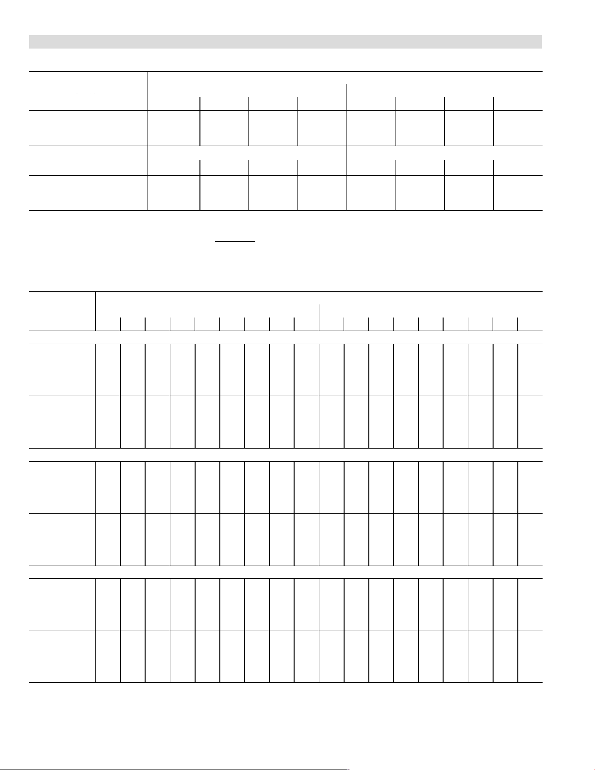
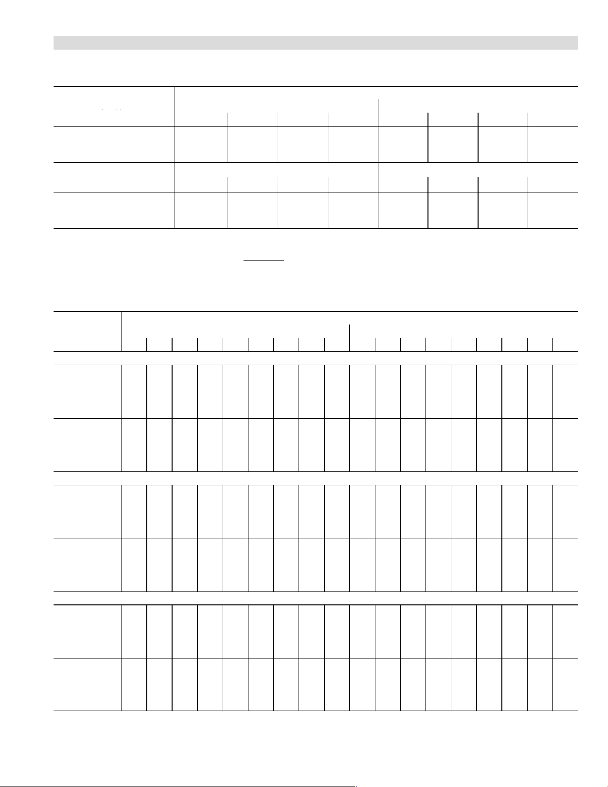
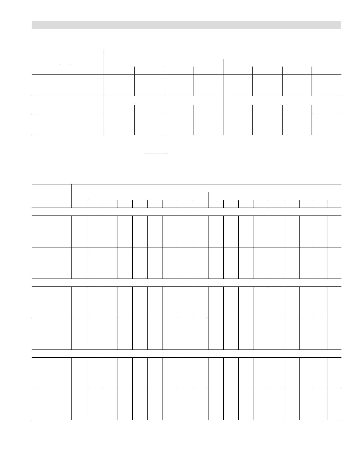
G61MPV−36B−070 BLOWER PERFORMANCE (less filter)
0 through 0.80 in. w.g. External Static Pressure Range
Switch
Positions
1
ADJUST"
Switch
Positions
1
1
Factory default jumper setting.
N/A − First and second stage HEAT positions shown cannot be used on this model.
NOTES − The effect of static pressure is included in air volumes shown.
First stage HEAT is approximately 91% of the same second stage
First stage COOL (two−stage air conditioning units only) is approximately 70% of the same second stage COOL speed position.
Continuous Fan Only speed is approximately 38% of the same second stage COOL speed position − minimum 500 cfm.
Lennox Harmony IIIt Zone Control Applications − Minimum blower speed is 458 cfm.
G61MPV−36B−070 BLOWER MOTOR WATTS
Jumper Speed
+" (Plus) SETTING (Adjust" Jumper at +" Setting)
HEAT"
Speed
Tap 1
Tap 2
Tap 3
Tap 4
COOL"
Speed
Tap 1
Tap 2
Tap 3
Tap 4
NORM" (Normal) SETTING (Adjust" Jumper at NORM" Setting)
HEAT"
Speed
Tap 1
Tap 2
Tap 3
Tap 4
COOL"
Speed
Tap 1
Tap 2
Tap 3
Tap 4
−" (Minus) SETTING (Adjust" Jumper at −" Setting)
HEAT"
Speed
Tap 1
Tap 2
Tap 3
Tap 4
COOL"
Speed
Tap 1
Tap 2
Tap 3
Tap 4
"
Second Stage HEAT" Speed − cfm Second Stage COOL" Speed − cfm
1
1
2 3 4 1 2 3
+ 895 1025 1290 1340 1015 1190 1280 1395
NORM 820 940 1155 1210 930 1065 1155 1270
N/A 840 1020 1055 830 950 1010 1105
First Stage HEAT" Speed − cfm First Stage COOL" Speed − cfm
1
1
2 3 4 1 2 3
+ 820 930 1160 1210 730 815 865 935
NORM 760 865 1045 1090 680 755 795 855
N/A 775 930 965 625 695 730 775
HEAT speed position.
Motor Watts @ Various External Static Pressures − in. wg.
First Stage Second Stage
0 0.1 0.2 0.3 0.4 0.5 0.6 0.7 0.8 0 0.1 0.2 0.3 0.4 0.5 0.6 0.7 0.8
70 85 105 130 150 170 190 205 225 110 11 5 135 155 175 195 215 240 260
120 145 165 190 215 235 260 280 130 155 180 205 230 255 280 300 325
100
210 240 270 290 310 345 375 405 250 280 310 340 370 400 425 450 475
185
200 230 265 295 325 355 385 410 440 285 310 340 365 400 430 455 485 510
55 70 90 110 130 145 160 175 190 135 155 175 200 220 245 270 295 320
75
90 11 0 130 150 170 190 205 220 185 215 250 285 315 345 370 395 420
85 100 120 145 165 185 205 225 250 235 265 300 335 370 400 425 455 480
125 150 170 190 210 235 255 280 315 340 370 395 440 480 510 540 570
105
65 75 95 110 130 150 170 185 200 75 90 110 125 150 170 190 205 225
85
100 120 140 160 180 200 225 245 100 120 145 165 190 210 230 250 270
155 180 205 235 265 285 305 325 195 210 230 250 280 315 340 370 395
130
145
170 200 230 255 280 305 330 355 200 225 255 280 315 355 375 400 425
45 60 80 95 115 130 145 160 175 100 120 140 165 190 215 235 255 275
60
75 95 11 0 130 145 165 180 200 140 165 190 220 245 265 290 315 340
65 85 105 125 140 155 175 195 215 175 200 230 260 285 310 340 365 390
85 100 120 140 160 180 200 220 240 230 260 295 325 360 390 410 435 455
N/A N/A N/A N/A N/A N/A N/A N/A N/A N/A N/A N/A N/A N/A N/A N/A N/A N/A
60
75 100 120 140 160 175 195 210 70 90 115 135 160 185 200 220 235
95 120 145 170 190 210 230 245 265 140 160 180 205 225 245 270 295 325
130 155 185 205 225 245 270 290 145 165 190 215 235 255 280 305 330
110
40 55 70 85 100 120 130 145 160 75 90 110 125 150 175 190 210 225
45
60 80 95 115 135 145 160 175 95 120 150 175 200 220 240 260 285
50 65 85 105 125 145 160 175 190 125 150 175 195 220 240 265 290 320
60 75 95 115 135 150 170 190 215 165 190 215 245 265 485 315 340 370
Speed Switch Positions
1
4
1
4
Page 5
Page 6
BLOWER DATA
ADJUST"
Stc
Positions
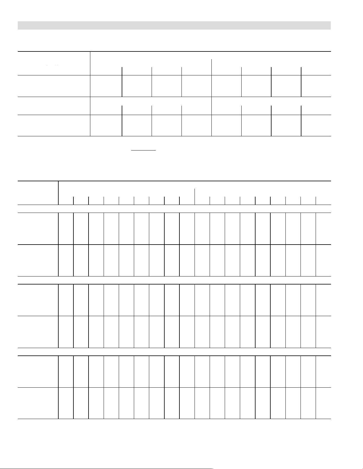
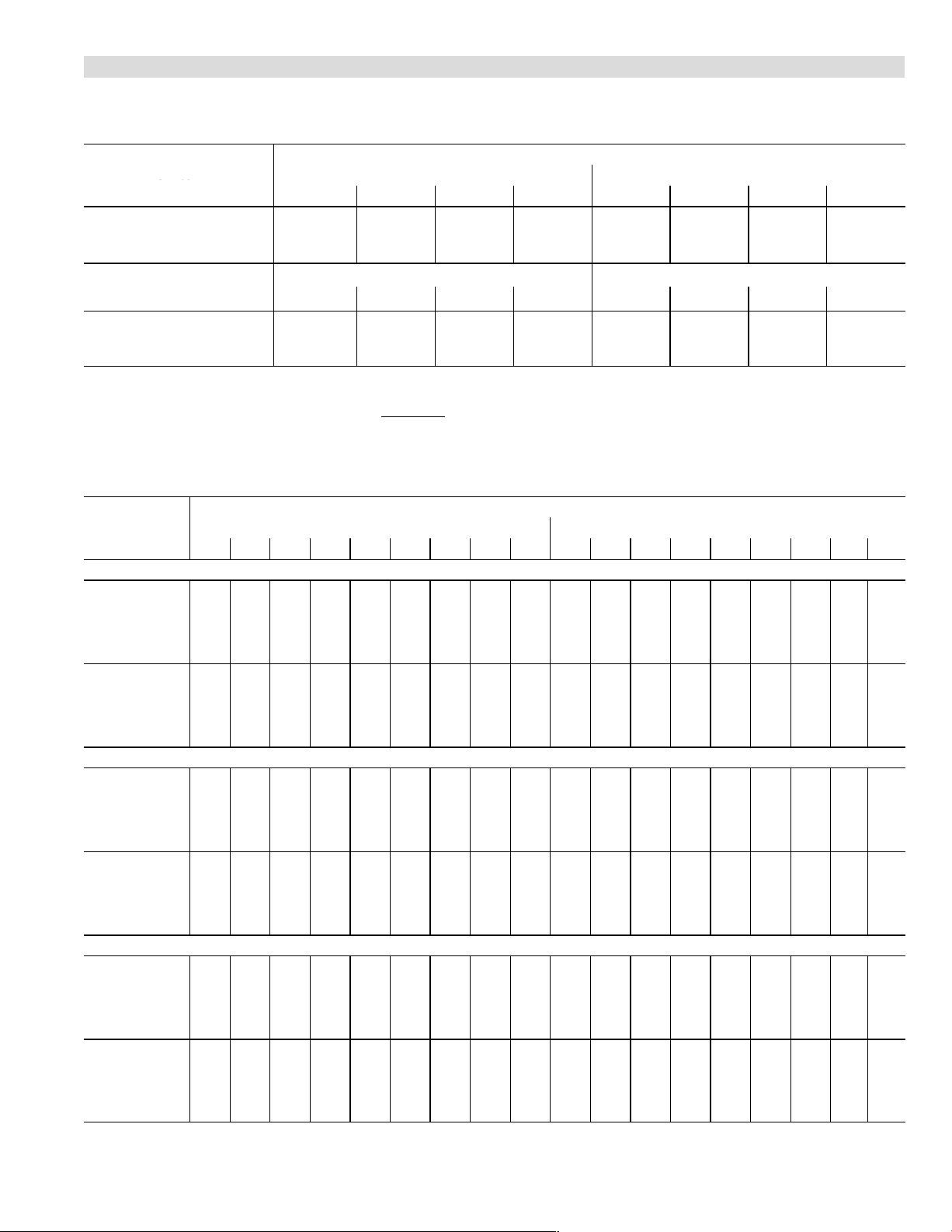
G61MPV−36B−071 BLOWER PERFORMANCE (less filter)
0 through 0.80 in. w.g. External Static Pressure Range
Switch
Positions
1
ADJUST"
Switch
Positions
1
1
Factory default jumper setting.
N/A − First and second stage HEAT positions shown cannot be used on this model.
NOTES − The effect of static pressure is included in air volumes shown.
First stage HEAT is approximately 91% of the same second stage
First stage COOL (two−stage air conditioning units only) is approximately 70% of the same second stage COOL speed position.
Continuous Fan Only speed is approximately 38% of the same second stage COOL speed position − minimum 500 cfm.
Lennox Harmony IIIt Zone Control Applications − Minimum blower speed is 458 cfm.
G61MPV−36B−071 BLOWER MOTOR WATTS
Jumper Speed
+" (Plus) SETTING (Adjust" Jumper at +" Setting)
HEAT"
Speed
Tap 1 70 90 11 0 135 160 180 195 215 240 100 120 140 165 190 210 235 255 275
Tap 2 115
Tap 3 205 230 265 295 325 355 380 410 425 290 320 350 380 415 440 465 490 480
Tap 4 220 250 290 325 360 390 425 455 455 310 345 375 410 445 475 500 525 515
COOL"
Speed
Tap 1 55 70 90 110 130 145 165 185 200 145 170 195 220 245 270 295 320 345
Tap 2 7 0
Tap 3 9 0 105 130 150 170 195 220 240 260 265 300 340 375 415 440 465 490 505
Tap 4 110 130 155 180 205 230 250 270 295 360 390 425 460 495 515 540 560 535
NORM" (Normal) SETTING (Adjust" Jumper at NORM" Setting)
HEAT"
Speed
Tap 1 60 75 95 115 135 155 175 195 215 75 95 11 5 140 160 180 200 220 240
Tap 2 8 0
Tap 3 150 170 200 225 250 275 300 325 350 210 235 260 285 315 345 375 405 425
Tap 4 165 190 220 250 280 310 335 360 385 230 260 290 325 355 380 405 430 435
COOL"
Speed
Tap 1 45 60 80 95 11 5 130 150 165 185 11 0 130 155 180 205 225 245 265 285
Tap 2 6 0
Tap 3 7 0 85 105 130 150 170 190 215 235 205 230 260 290 320 350 380 410 420
Tap 4 8 0 100 125 150 170 195 215 240 260 260 290 320 355 390 415 440 470 480
−" (Minus) SETTING (Adjust" Jumper at −" Setting)
HEAT"
Speed
Tap 1 50 65 85 100 120 140 155 175 195 70 90 105 125 145 165 185 205 215
Tap 2 6 5
Tap 3 105 125 150 180 205 225 245 265 290 145 170 195 225 255 270 290 305 325
Tap 4 115 135 165 190 215 240 260 285 310 160 185 215 240 270 290 310 330 350
COOL"
Speed
Tap 1 40 55 70 85 100 120 135 155 170 75 95 120 140 165 185 205 225 245
Tap 2 4 5
Tap 3 5 5 70 90 110 130 150 165 185 205 140 165 190 215 245 265 290 315 340
Tap 4 60 75 100 120 140 165 185 205 225 180 205 235 265 295 320 345 365 390
"
Second Stage HEAT" Speed − cfm Second Stage COOL" Speed − cfm
1
1
2 3 4 1 2 3
+ 925 1065 1305 1345 1055 1225 1305 1405
NORM 840 970 1185 1230 955 1100 1185 1280
775 875 1050 1085 855 975 1040 1140
First Stage HEAT" Speed − cfm First Stage COOL" Speed − cfm
1
1
2 3 4 1 2 3
+ 840 965 1190 1235 745 835 895 970
NORM 765 880 1070 1115 695 770 815 875
705 795 955 990 645 705 740 790
HEAT speed position.
Motor Watts @ Various External Static Pressures − in. wg.
First Stage Second Stage
0 0.1 0.2 0.3 0.4 0.5 0.6 0.7 0.8 0 0.1 0.2 0.3 0.4 0.5 0.6 0.7 0.8
135 160 185 205 230 250 270 295 160 185 210 230 255 275 295 315 330
90 11 5 135 160 180 200 220 240 225 255 285 315 350 375 400 425 445
100 125 150 180 200 220 240 255 11 0 135 165 190 220 240 255 275 290
75 95 115 135 155 170 190 215 160 185 215 245 280 305 330 355 375
80 100 120 140 165 185 205 225 90 11 0 130 155 175 195 215 235 250
60 80 100 115 135 150 170 185 115 135 160 190 215 235 255 270 295
Speed Switch Positions
1
4
1
4
Page 6
Page 7

BLOWER DATA
ADJUST"
Stc
Positions
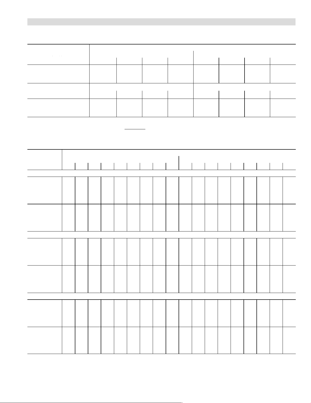
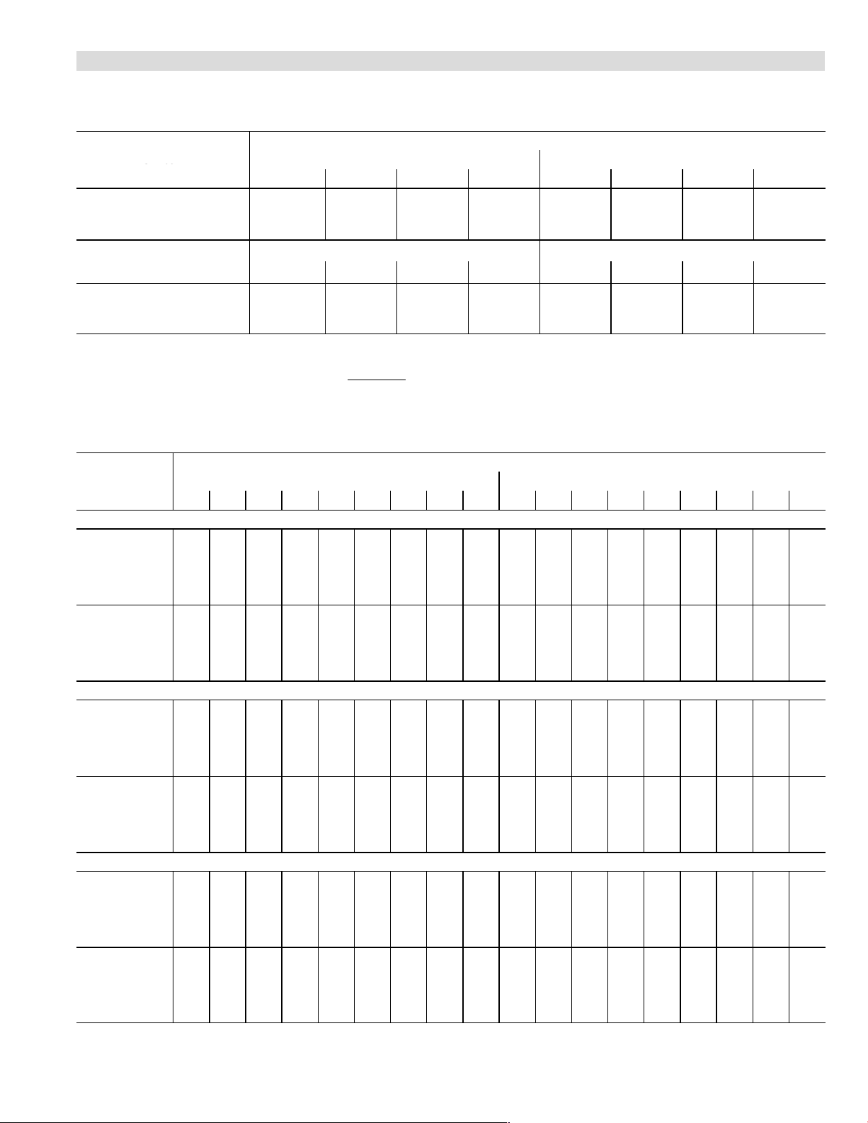
G61MPV−36C−090 BLOWER PERFORMANCE (less filter)
0 through 0.80 in. w.g. External Static Pressure Range
Switch
Positions
1
ADJUST"
Switch
Positions
1
1
Factory default jumper setting.
N/A − First and second stage HEAT positions shown cannot be used on this model.
NOTES − The effect of static pressure is included in air volumes shown.
First stage HEAT is approximately 91% of the same second stage
First stage COOL (two−stage air conditioning units only) is approximately 70% of the same second stage COOL speed position.
Continuous Fan Only speed is approximately 38% of the same second stage COOL speed position − minimum 500 cfm.
Lennox Harmony IIIt Zone Control Applications − Minimum blower speed is 479 cfm.
G61MPV−36C−090 BLOWER MOTOR WATTS
Jumper Speed
+" (Plus) SETTING (Adjust" Jumper at +" Setting)
HEAT"
Speed
Tap 1
Tap 2
Tap 3
Tap 4
COOL"
Speed
Tap 1
Tap 2
Tap 3
Tap 4
NORM" (Normal) SETTING (Adjust" Jumper at NORM" Setting)
HEAT"
Speed
Tap 1
Tap 2
Tap 3
Tap 4
COOL"
Speed
Tap 1
Tap 2
Tap 3
Tap 4
−" (Minus) SETTING (Adjust" Jumper at −" Setting)
HEAT"
Speed
Tap 1
Tap 2
Tap 3
Tap 4
COOL"
Speed
Tap 1
Tap 2
Tap 3
Tap 4
"
Second Stage HEAT" Speed − cfm Second Stage COOL" Speed − cfm
1
1
2 3 4 1 2 3
+ N/A 1040 1285 1340 1020 1185 1275 1395
NORM N/A 915 1150 1200 905 1060 1145 1270
N/A N/A 1020 1055 800 925 1010 1100
First Stage HEAT" Speed − cfm First Stage COOL" Speed − cfm
1
1
2 3 4 1 2 3
+ N/A 940 1160 1210 705 790 845 920
NORM N/A 840 1040 1075 650 730 770 830
N/A N/A 915 945 600 670 705 750
HEAT speed position.
Motor Watts @ Various External Static Pressures − in. wg.
First Stage Second Stage
0 0.1 0.2 0.3 0.4 0.5 0.6 0.7 0.8 0 0.1 0.2 0.3 0.4 0.5 0.6 0.7 0.8
N/A N/A N/A N/A N/A N/A N/A N/A N/A N/A N/A N/A N/A N/A N/A N/A N/A N/A
90 11 0 130 155 185 205 225 250 90 110 140 165 185 205 235 260 290
75
150 175 200 230 260 290 325 355 170 195 230 265 290 330 360 395 425
125
130 160 200 235 265 295 325 355 385 185 220 255 290 325 360 395 430 460
35 50 70 90 105 125 140 160 175 85 110 135 160 185 205 235 265 295
45
60 80 100 125 150 170 185 205 125 155 185 220 245 275 305 330 360
60 75 95 110 135 160 180 200 220 165 195 230 265 300 330 355 380 410
85 11 0 135 160 180 205 225 245 210 245 285 325 360 390 425 460 495
65
N/A N/A N/A N/A N/A N/A N/A N/A N/A N/A N/A N/A N/A N/A N/A N/A N/A N/A
50
65 90 11 0 135 155 175 200 220 60 80 105 130 155 185 205 220 240
110 145 175 200 225 245 270 290 110 135 170 205 230 250 285 320 355
90
90
120 155 190 205 225 250 280 305 140 165 190 220 255 290 315 335 360
35 45 60 75 95 115 130 145 160 60 80 110 135 155 175 195 215 235
40
55 70 90 110 130 150 165 185 105 125 145 170 200 225 250 270 295
45 60 80 95 115 135 155 175 195 115 140 175 205 235 265 290 315 335
50 65 85 105 130 155 180 200 220 155 185 220 255 285 315 345 380 415
N/A N/A N/A N/A N/A N/A N/A N/A N/A N/A N/A N/A N/A N/A N/A N/A N/A N/A
N/A
N/A N/A N/A N/A N/A N/A N/A N/A N/A N/A N/A N/A N/A N/A N/A N/A N/A
65 85 105 130 155 180 200 225 250 85 105 135 160 185 205 230 250 270
95 120 140 165 190 210 230 250 90 115 140 170 190 215 245 275 305
75
30 40 55 75 90 105 120 135 150 55 65 85 105 125 150 170 190 210
40
50 65 80 100 120 130 145 160 65 90 120 145 165 185 205 225 250
40 55 70 90 105 125 140 160 180 85 105 135 165 185 210 235 260 285
45 60 75 90 115 135 155 170 190 105 125 150 175 210 240 275 305 335
Speed Switch Positions
1
4
1
4
Page 7
Page 8
BLOWER DATA
ADJUST"
Stc
Positions
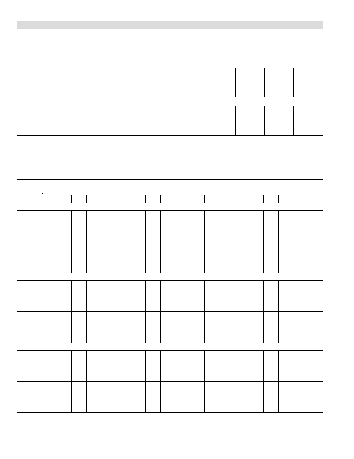
G61MPV−60C−090 BLOWER PERFORMANCE (less filter)
Bottom Return Air, Return Air from Both Sides or Return Air from Bottom and One Side.
0 through 0.80 in. w.g. External Static Pressure Range
Switch
Positions
"
Second Stage HEAT" Speed − cfm Second Stage COOL" Speed − cfm
1
2 3 4 1 2 3
1
+ 1500 1675 1880 2090 1605 1710 1925 2165
1
NORM 1355 1545 1720 1900 1440 1560 1755 1960
1194 1365 1540 1695 1275 1380 1590 1755
ADJUST"
Switch
Positions
First Stage HEAT" Speed − cfm First Stage COOL" Speed − cfm
1
1
2 3 4 1 2 3
+ 1360 1560 1730 1910 1105 1185 1355 1545
1
NORM 1220 1405 1585 1740 995 1080 1205 1345
1105 1235 1410 1570 890 960 1090 1215
1
Factory default jumper setting.
NOTES − The effect of static pressure is included in air volumes shown.
First stage HEAT is approximately 91% of the same second stage
First stage COOL (two−stage air conditioning units only) is approximately 70% of the same second stage COOL speed position.
Continuous Fan Only speed is approximately 38% of the same second stage COOL speed position − minimum 500 cfm.
Lennox Harmony IIIt Zone Control Applications − Minimum blower speed is 449 cfm.
HEAT speed position.
G61MPV−60C−090 BLOWER MOTOR WATTS
Motor Watts @ Various External Static Pressures − in. wg.
Jumper Speed
First Stage Second Stage
0 0.1 0.2 0.3 0.4 0.5 0.6 0.7 0.8 0 0.1 0.2 0.3 0.4 0.5 0.6 0.7 0.8
+" (Plus) SETTING (Adjust" Jumper at +" Setting)
HEAT"
Speed
COOL"
Speed
190 215 245 275 305 340 365 390 420 245 275 315 350 380 410 440 475 510
Tap 1
265
Tap 2
Tap 3
Tap 4
Tap 1
Tap 2
Tap 3
Tap 4
300 340 380 415 450 480 510 540 350 385 420 455 490 525 555 580 610
380 415 450 485 520 555 595 630 665 485 520 555 595 640 685 720 755 790
495 535 580 625 660 700 735 770 805 650 695 750 800 850 900 925 955 985
115 135 160 185 205 230 255 275 300 305 340 375 410 440 475 505 535 565
145
165 190 215 240 265 285 305 325 355 390 430 470 510 550 580 610 635
170 200 240 275 305 335 370 400 430 510 555 600 645 690 730 765 795 830
265 295 330 365 400 435 465 500 535 725 780 835 895 935 975 1005 1035 1065
NORM" (Normal) SETTING (Adjust" Jumper at NORM" Setting)
HEAT"
Speed
COOL"
Speed
150 170 195 220 245 270 295 325 350 180 210 245 280 305 330 365 400 430
Tap 1
200
Tap 2
Tap 3
Tap 4
Tap 1
Tap 2
Tap 3
Tap 4
230 270 305 330 355 385 415 450 265 295 335 375 405 430 465 500 535
270 310 355 395 425 460 490 525 560 370 400 435 470 515 555 585 615 645
390 420 455 490 525 555 595 630 670 495 530 570 605 645 685 720 755 795
90 11 0 130 155 175 195 215 235 255 220 250 285 320 350 385 415 450 485
110
130 155 180 200 220 245 265 285 270 305 345 385 420 455 485 515 545
145
165 190 215 245 270 295 320 340 390 425 465 500 540 580 610 640 670
205 240 270 300 330 365 395 430 540 580 625 670 710 755 795 830 870
180
−" (Minus) SETTING (Adjust" Jumper at −" Setting)
HEAT"
Speed
COOL"
Speed
110 135 165 190 215 235 255 280 300 155 175 195 215 245 270 295 315 340
Tap 1
155
Tap 2
Tap 3
Tap 4
Tap 1
Tap 2
Tap 3
Tap 4
175 200 225 255 285 310 335 365 190 215 250 285 310 335 365 395 425
200
230 270 305 335 365 395 420 450 255 290 335 375 400 430 465 495 530
270 305 345 385 415 450 480 515 545 345 385 425 465 495 530 565 605 645
70 85 105 125 145 165 185 205 225 160 190 220 255 275 300 330 360 390
80
100 120 140 165 190 210 225 245 195 225 260 295 325 350 385 415 450
110 130 160 185 205 225 250 275 300 295 330 365 400 430 460 495 535 570
155 175 195 220 245 270 295 315 340 400 435 470 510 545 585 610 640 665
Speed Switch Positions
1
4
1
4
Page 8
Page 9
BLOWER DATA
ADJUST"
Stc
Positions
G61MPV−60C−090 BLOWER PERFORMANCE (less filter)
Side Return Air with Optional RAB Return Air Base
0 through 0.80 in. w.g. External Static Pressure Range
Switch
Positions
1
ADJUST"
Switch
Positions
1
1
Factory default jumper setting.
NOTES − The effect of static pressure is included in air volumes shown.
First stage HEAT is approximately 91% of the same second stage
First stage COOL (two−stage air conditioning units only) is approximately 70% of the same second stage COOL speed position.
Continuous Fan Only speed is approximately 38% of the same second stage COOL speed position − minimum 500 cfm.
Lennox Harmony IIIt Zone Control Applications − Minimum blower speed is 449 cfm.
G61MPV−60C−090 BLOWER MOTOR WATTS
Jumper Speed
+" (Plus) SETTING (Adjust" Jumper at +" Setting)
HEAT"
Speed
Tap 1
Tap 2
Tap 3
Tap 4
COOL"
Speed
Tap 1
Tap 2
Tap 3
Tap 4
NORM" (Normal) SETTING (Adjust" Jumper at NORM" Setting)
HEAT"
Speed
Tap 1
Tap 2
Tap 3
Tap 4
COOL"
Speed
Tap 1
Tap 2
Tap 3
Tap 4
−" (Minus) SETTING (Adjust" Jumper at −" Setting)
HEAT"
Speed
Tap 1
Tap 2
Tap 3
Tap 4
COOL"
Speed
Tap 1
Tap 2
Tap 3
Tap 4
"
Second Stage HEAT" Speed − cfm Second Stage COOL" Speed − cfm
1
2 3 4 1 2 3
1
+ 1440 1630 1810 2015 1525 1655 1860 2100
NORM 1300 1485 1655 1830 1385 1500 1695 1905
1155 1310 1480 1640 1240 1320 1510 1695
First Stage HEAT" Speed − cfm First Stage COOL" Speed − cfm
1
1
2 3 4 1 2 3
+ 1320 1490 1665 1840 1060 1135 1285 1455
NORM 1180 1345 1515 1680 960 1035 1165 1310
1055 1180 1340 1490 865 920 1050 1165
HEAT speed position.
Motor Watts @ Various External Static Pressures − in. wg.
First Stage Second Stage
0 0.1 0.2 0.3 0.4 0.5 0.6 0.7 0.8 0 0.1 0.2 0.3 0.4 0.5 0.6 0.7 0.8
180 205 235 260 290 320 350 380 410 230 260 290 320 355 390 420 445 475
250
280 315 350 385 425 455 485 515 325 360 400 435 465 495 530 565 595
345 380 415 455 485 515 550 580 615 460 490 520 550 595 640 675 715 750
465 505 545 585 625 660 695 730 760 665 685 710 735 775 820 860 900 940
110 130 150 175 195 215 240 265 290 275 305 340 380 410 440 470 505 540
130
155 175 200 220 245 265 290 315 360 390 420 455 485 515 550 590 625
160
190 220 255 280 305 335 360 390 490 530 570 610 645 680 715 750 785
220 255 295 330 365 400 430 460 490 695 750 805 855 895 935 965 995 1025
145 165 190 210 235 260 285 310 335 170 195 230 260 290 320 350 375 400
195
220 250 275 305 335 365 395 420 255 285 315 345 370 395 430 465 500
280 305 335 360 395 425 455 485 515 340 375 410 450 480 510 545 580 615
370 400 430 460 495 530 565 595 625 465 500 535 575 610 645 685 725 765
80 95 120 140 165 190 210 235 255 190 225 265 305 330 355 390 420 455
100
120 140 165 190 215 235 255 275 265 295 325 355 390 420 455 495 530
140
160 185 205 235 260 285 305 325 375 410 440 475 500 530 570 610 650
205 240 270 300 325 350 380 405 520 560 605 645 685 720 760 805 845
180
100 125 150 175 200 220 245 265 290 135 155 180 200 225 250 275 300 330
150
165 185 205 235 265 290 310 335 170 200 235 265 290 320 350 375 405
210
230 255 275 310 345 370 400 425 255 285 315 350 370 390 430 470 510
260 290 320 350 390 430 455 480 505 340 375 410 445 475 510 535 565 590
70 85 105 125 140 160 180 200 220 155 175 200 225 255 290 315 340 365
80
95 11 5 135 155 175 200 220 245 185 210 235 260 295 325 355 385 415
105 125 150 175 200 220 240 265 290 255 290 330 365 400 430 460 490 520
135 160 185 215 235 260 285 305 330 370 400 440 475 505 530 565 600 635
Speed Switch Positions
1
4
1
4
Page 9
Page 10
BLOWER DATA
ADJUST"
Stc
Positions
G61MPV−60C−090 BLOWER PERFORMANCE (less filter)
Single Side Return Air − Air volumes in bold require field fabricated transition to accommodate 20 x 25 x 1 in. cleanable air filter in
order to maintain proper air velocity across the filter.
0 through 0.80 in. w.g. External Static Pressure Range
Switch
Positions
"
Second Stage HEAT" Speed − cfm Second Stage COOL" Speed − cfm
1
1
2 3 4 1 2 3
+ 1450 1640 1820 2055 1575 1690 1895 2135
1
NORM 1320 1510 1700 1870 1405 1530 1735 1935
1165 1320 1500 1665 1250 1355 1560 1735
ADJUST"
Switch
Positions
First Stage HEAT" Speed − cfm First Stage COOL" Speed − cfm
1
1
2 3 4 1 2 3
+ 1315 1510 1695 1875 1080 1160 1315 1490
1
NORM 1190 1365 1545 1715 985 1060 1185 1330
1075 1205 1370 1520 865 930 1065 1185
1
Factory default jumper setting.
NOTES − The effect of static pressure is included in air volumes shown.
First stage HEAT is approximately 91% of the same second stage
First stage COOL (two−stage air conditioning units only) is approximately 70% of the same second stage COOL speed position.
Continuous Fan Only speed is approximately 38% of the same second stage COOL speed position − minimum 500 cfm.
Lennox Harmony IIIt Zone Control Applications − Minimum blower speed is 449 cfm.
HEAT speed position.
G61MPV−60C−090 BLOWER MOTOR WATTS
Motor Watts @ Various External Static Pressures − in. wg.
Jumper Speed
First Stage Second Stage
0 0.1 0.2 0.3 0.4 0.5 0.6 0.7 0.8 0 0.1 0.2 0.3 0.4 0.5 0.6 0.7 0.8
+" (Plus) SETTING (Adjust" Jumper at +" Setting)
HEAT"
Speed
COOL"
Speed
170 200 230 265 295 325 355 385 415 225 255 290 325 360 390 425 455 490
Tap 1
285 320 355 390 425 455 490 520 330 370 410 455 485 515 540 560 585
255
Tap 2
345 385 430 475 515 555 585 610 640 445 480 520 560 610 660 700 735 775
Tap 3
470 515 560 610 650 685 725 765 800 650 695 745 800 840 885 915 950 980
Tap 4
110 130 155 180 205 225 245 270 290 285 320 355 390 430 465 500 535 565
Tap 1
125
Tap 2
Tap 3
Tap 4
150 175 205 225 250 275 300 325 355 390 430 470 500 530 570 605 645
170 195 230 260 290 325 355 385 415 515 550 590 625 670 710 750 795 840
240 275 315 355 380 405 445 485 525 740 785 835 885 920 955 990 1020 1050
NORM" (Normal) SETTING (Adjust" Jumper at NORM" Setting)
HEAT"
Speed
COOL"
Speed
145 165 190 215 240 265 290 315 345 175 200 235 265 300 330 360 385 415
Tap 1
195
Tap 2
Tap 3
Tap 4
Tap 1
Tap 2
Tap 3
Tap 4
225 255 290 320 345 375 405 435 260 290 325 355 390 425 455 490 520
265 300 335 370 405 435 470 505 540 360 395 435 470 515 555 585 620 650
385
420 460 495 525 555 590 625 660 475 515 560 600 640 685 720 760 800
85 100 125 145 170 200 215 235 255 200 230 270 310 340 370 400 430 460
105
125 150 170 195 220 240 260 280 260 295 330 365 400 440 470 500 530
135 160 185 215 240 270 290 315 335 410 440 470 500 540 580 610 640 670
170 200 235 265 305 340 365 390 415 550 585 620 655 695 740 780 825 865
−" (Minus) SETTING (Adjust" Jumper at −" Setting)
HEAT"
Speed
COOL"
Speed
105 130 155 180 205 225 245 270 290 130 155 180 204 230 260 285 310 335
Tap 1
145
Tap 2
Tap 3
Tap 4
Tap 1
Tap 2
Tap 3
Tap 4
165 195 220 250 280 305 335 360 170 195 230 265 295 325 355 385 420
190 220 250 285 315 345 375 405 440 245 280 315 350 385 420 450 485 520
295 325 355 395 430 465 500 530 340 375 415 455 490 525 560 595 625
270
65 80 100 120 140 160 180 205 225 155 180 215 245 265 290 320 345 375
75
90 11 0 130 155 180 200 220 245 190 220 250 275 305 335 370 400 430
100 120 150 175 200 220 245 265 290 290 320 355 385 415 445 485 520 560
135 160 185 215 240 265 290 315 335 405 435 465 495 540 585 610 640 665
Speed Switch Positions
1
4
1
4
Page 10
Page 11
BLOWER DATA
ADJUST"
Stc
Positions
G61MPV−60C−091 BLOWER PERFORMANCE (less filter)
Bottom Return Air, Return Air from Both Sides or Return Air from Bottom and One Side.
0 through 1.00 in. w.g. External Static Pressure Range
Switch
Positions
"
Second Stage HEAT" Speed − cfm Second Stage COOL" Speed − cfm
1
2 3 4 1 2 3
1
+ 1560 1770 1895 2110 1665 1790 1990 2175
1
NORM 1400 1575 1745 1930 1515 1625 1815 2020
1245 1400 1565 1745 1340 1445 1645 1800
ADJUST"
Switch
Positions
First Stage HEAT" Speed − cfm First Stage COOL" Speed − cfm
1
1
2 3 4 1 2 3
+ 1420 1625 1780 1965 1240 1245 1410 1585
1
NORM 1280 1465 1615 1790 1060 1125 1270 1430
1145 1290 1445 1610 940 1015 1145 1270
1
Factory default jumper setting.
N/A − First and second stage HEAT positions shown cannot be used on this model.
NOTES − The effect of static pressure is included in air volumes shown.
First stage HEAT is approximately 91% of the same second stage
First stage COOL (two−stage air conditioning units only) is approximately 70% of the same second stage COOL speed position.
Continuous Fan Only speed is approximately 38% of the same second stage COOL speed position − minimum 500 cfm.
Lennox Harmony IIIt Zone Control Applications − Minimum blower speed is 458 cfm.
HEAT speed position.
G61MPV−60C−091 BLOWER MOTOR WATTS
Motor Watts @ Various External Static Pressures − in. wg.
Jumper Speed
First Stage Second Stage
0 0.1 0.2 0.3 0.4 0.5 0.6 0.7 0.8 0 0.1 0.2 0.3 0.4 0.5 0.6 0.7 0.8
+" (Plus) SETTING (Adjust" Jumper at +" Setting)
HEAT"
Tap 1 255 280 305 330 355 390 420 450 475 305 340 375 415 450 475 505 530 560
Speed
Tap 2 325
360 390 425 460 500 540 580 615 395 440 490 540 585 620 655 690 730
Tap 3 495 525 555 590 620 650 680 710 710 615 645 675 705 740 755 775 790 765
Tap 4 625 660 700 740 780 815 855 890 890 800 840 880 920 960 985 1005 1030 1000
COOL"
Tap 1 180 200 225 250 280 300 320 345 370 390 420 455 485 520 550 585 615 640
Speed
Tap 2 200
225 250 280 305 330 350 375 395 485 520 555 590 625 655 680 710 735
Tap 3 245 270 300 335 365 390 420 445 470 655 700 740 785 830 860 890 925 930
Tap 4 355 380 405 435 465 495 520 550 585 930 960 990 1020 1050 1060 1070 1045 1005
NORM" (Normal) SETTING (Adjust" Jumper at NORM" Setting)
HEAT"
Tap 1 185 210 235 265 290 315 340 365 390 230 260 290 320 350 375 405 430 460
Speed
Tap 2 240
270 305 340 375 410 445 475 505 300 335 370 410 450 485 520 560 595
Tap 3 385 410 435 455 480 510 540 656 595 465 495 530 565 595 625 650 680 690
Tap 4 480 510 540 570 600 605 670 705 740 585 626 670 710 750 785 820 855 870
COOL"
Tap 1 110 130 155 180 205 230 250 275 295 285 315 350 380 415 440 465 490 525
Speed
Tap 2 140
160 185 205 230 250 265 285 310 345 380 420 460 495 525 550 580 615
Tap 3 185 210 235 265 290 320 350 380 395 485 525 565 610 650 680 715 745 775
Tap 4 245 275 305 335 365 395 420 450 480 680 720 765 810 855 885 910 940 960
−" (Minus) SETTING (Adjust" Jumper at −" Setting)
HEAT"
Tap 1 145 165 190 210 235 255 280 300 320 175 195 225 250 275 295 320 340 365
Speed
Tap 2 175
200 225 255 280 305 335 360 385 220 250 280 315 350 375 400 430 460
Tap 3 275 305 330 360 385 410 435 460 485 365 390 410 435 460 485 510 535 555
Tap 4 340 370 405 440 475 505 535 570 600 460 490 520 550 580 610 640 675 700
COOL"
Tap 1 90 105 125 145 165 185 205 225 245 215 240 270 300 325 350 375 395 425
Speed
Tap 2 105
125 150 170 195 215 235 255 270 255 285 315 345 380 405 430 455 495
Tap 3 145 165 190 215 235 260 280 305 325 385 410 440 470 495 535 570 605 630
Tap 4 190 215 240 265 290 315 345 370 395 485 520 555 590 625 660 700 735 765
Speed Switch Positions
1
4
1
4
Page 11
Page 12

BLOWER DATA
ADJUST"
Stc
Positions
G61MPV−60C−091 BLOWER PERFORMANCE (less filter)
Side Return Air with Optional RAB Return Air Base
0 through 1.00 in. w.g. External Static Pressure Range
Switch
Positions
1
ADJUST"
Switch
Positions
1
1
Factory default jumper setting.
N/A − First and second stage HEAT positions shown cannot be used on this model.
NOTES − The effect of static pressure is included in air volumes shown.
First stage HEAT is approximately 91% of the same second stage
First stage COOL (two−stage air conditioning units only) is approximately 70% of the same second stage COOL speed position.
Continuous Fan Only speed is approximately 38% of the same second stage COOL speed position − minimum 500 cfm.
Lennox Harmony IIIt Zone Control Applications − Minimum blower speed is 458 cfm.
G61MPV−60C−091 BLOWER MOTOR WATTS
Jumper Speed
+" (Plus) SETTING (Adjust" Jumper at +" Setting)
HEAT"
Speed
Tap 1 210 235 265 295 325 350 380 405 435 265 295 330 365 400 425 450 480 500
Tap 2 270
Tap 3 430 455 490 520 550 580 610 645 675 530 656 600 640 675 700 730 755 775
Tap 4 525 560 600 635 675 710 750 790 825 680 725 775 820 870 905 935 970 995
COOL"
Speed
Tap 1 145 165 185 210 230 255 275 295 315 353 380 410 440 470 500 530 555 580
Tap 2 175
Tap 3 230 260 285 315 345 370 395 420 450 640 680 725 765 810 840 870 905 890
Tap 4 335 365 390 415 445 470 500 525 560 855 885 915 940 970 970 965 965 935
NORM" (Normal) SETTING (Adjust" Jumper at NORM" Setting)
HEAT"
Speed
Tap 1 160 185 210 235 260 280 305 325 355 195 225 255 285 320 345 365 390 420
Tap 2 205
Tap 3 325 350 375 400 430 455 475 500 530 415 445 475 505 540 570 605 635 665
Tap 4 410 445 475 510 545 575 605 640 670 505 545 585 625 660 700 740 780 815
COOL"
Speed
Tap 1 105 125 150 170 195 220 240 261 280 260 285 315 345 375 400 420 445 475
Tap 2 135
Tap 3 175 200 225 250 275 305 330 360 375 475 515 555 595 635 665 695 730 760
Tap 4 235 260 290 320 350 375 405 430 460 625 665 705 750 790 815 840 865 855
−" (Minus) SETTING (Adjust" Jumper at −" Setting)
HEAT"
Speed
Tap 1 120 140 165 190 215 235 260 285 305 150 170 195 220 245 270 295 320 345
Tap 2 145
Tap 3 230 255 285 315 345 370 395 420 445 310 335 365 390 415 445 470 495 520
Tap 4 280 315 350 385 420 450 480 515 540 385 415 445 480 515 545 580 610 640
COOL"
Speed
Tap 1 85 100 120 140 160 180 195 215 235 195 220 245 270 295 315 335 360 385
Tap 2 100
Tap 3 140 155 180 200 225 245 265 285 305 375 400 430 455 485 520 555 590 620
Tap 4 180 205 230 255 280 305 330 355 380 450 480 515 545 580 610 645 675 705
"
Second Stage HEAT" Speed − cfm Second Stage COOL" Speed − cfm
1
2 3 4 1 2 3
1
+ 1490 1690 1850 2050 1590 1695 1905 2035
NORM 1345 1520 1700 1870 1445 1535 1740 1900
1195 1345 1525 1675 1280 1370 1580 1700
First Stage HEAT" Speed − cfm First Stage COOL" Speed − cfm
1
1
2 3 4 1 2 3
+ 1360 1550 1720 1880 1125 1195 1370 1530
NORM 1225 1400 1540 1715 1030 1085 1230 1380
1100 1225 1385 1540 915 980 1110 1225
HEAT speed position.
Motor Watts @ Various External Static Pressures − in. wg.
First Stage Second Stage
0 0.1 0.2 0.3 0.4 0.5 0.6 0.7 0.8 0 0.1 0.2 0.3 0.4 0.5 0.6 0.7 0.8
300 340 380 415 450 485 520 555 355 395 445 490 535 570 610 645 675
195 220 245 270 290 315 335 360 445 475 510 540 575 600 625 650 675
235 265 295 330 355 385 415 450 250 285 325 365 405 435 465 495 530
155 180 200 225 240 260 275 300 320 350 385 420 455 480 505 530 565
170 200 225 255 285 315 345 370 185 210 240 270 305 330 360 390 425
120 145 165 190 210 230 250 265 235 260 290 320 345 370 395 420 455
Speed Switch Positions
1
4
1
4
Page 12
Page 13
BLOWER DATA
ADJUST"
Stc
Positions
G61MPV−60C−091 BLOWER PERFORMANCE (less filter)
Single Side Return Air − Air volumes in bold require field fabricated transition to accommodate 20 x 25 x 1 in. cleanable air filter in
order to maintain proper air velocity across the filter.
0 through 1.00 in. w.g. External Static Pressure Range
Switch
Positions
"
Second Stage HEAT" Speed − cfm Second Stage COOL" Speed − cfm
1
1
2 3 4 1 2 3
+ 1510 1720 1810 2065 1615 1735 1900 2055
1
NORM 1365 1535 1725 1880 1465 1575 1735 1915
1210 1360 1520 1700 1300 1400 1575 1715
ADJUST"
Switch
Positions
First Stage HEAT" Speed − cfm First Stage COOL" Speed − cfm
1
1
2 3 4 1 2 3
+ 1385 1560 1755 1900 1150 1220 1385 1545
1
NORM 1240 1400 1570 1750 1050 1105 1245 1395
1125 1260 1410 1560 930 995 1125 1240
1
Factory default jumper setting.
N/A − First and second stage HEAT positions shown cannot be used on this model.
NOTES − The effect of static pressure is included in air volumes shown.
First stage HEAT is approximately 91% of the same second stage
First stage COOL (two−stage air conditioning units only) is approximately 70% of the same second stage COOL speed position.
Continuous Fan Only speed is approximately 38% of the same second stage COOL speed position − minimum 500 cfm.
Lennox Harmony IIIt Zone Control Applications − Minimum blower speed is 458 cfm.
HEAT speed position.
G61MPV−60C−091 BLOWER MOTOR WATTS
Motor Watts @ Various External Static Pressures − in. wg.
Jumper Speed
First Stage Second Stage
0 0.1 0.2 0.3 0.4 0.5 0.6 0.7 0.8 0 0.1 0.2 0.3 0.4 0.5 0.6 0.7 0.8
+" (Plus) SETTING (Adjust" Jumper at +" Setting)
HEAT"
Speed
Tap 1 230 255 285 315 350 375 400 425 455 285 315 350 385 420 450 485 515 545
Tap 2 290
325 365 405 445 480 510 545 585 370 410 455 500 545 585 625 670 705
Tap 3 475 505 545 580 620 645 670 695 695 560 595 625 660 695 720 745 770 755
Tap 4 570 610 655 700 740 775 805 835 835 750 790 835 880 925 960 995 1025 1010
COOL"
Speed
Tap 1 155 175 200 225 250 275 295 320 345 385 415 450 485 515 545 580 610 635
Tap 2 175
200 225 250 275 300 320 340 370 470 500 535 570 600 630 655 685 710
Tap 3 240 265 295 325 355 385 410 435 465 645 685 730 770 815 845 875 905 890
Tap 4 355 380 410 440 465 495 525 555 590 905 935 965 995 1025 1025 1020 1020 985
NORM" (Normal) SETTING (Adjust" Jumper at NORM" Setting)
HEAT"
Speed
Tap 1 160 190 220 250 280 305 325 350 375 215 240 270 300 330 360 390 415 445
Tap 2 205
235 275 315 350 380 415 445 475 270 305 345 385 420 455 495 530 565
Tap 3 360 385 415 440 465 490 515 540 570 450 480 515 545 580 605 630 660 690
Tap 4 455 485 520 550 585 615 650 680 715 555 590 630 675 715 745 780 810 850
COOL"
Speed
Tap 1 115 135 160 185 210 235 260 280 300 285 315 345 380 410 435 460 485 520
Tap 2 135
160 180 205 230 245 265 280 305 335 365 405 440 480 505 530 560 595
Tap 3 180 205 230 260 285 315 345 370 390 475 515 555 595 640 670 700 730 760
Tap 4 245 275 305 335 370 395 425 450 485 660 705 750 790 835 865 890 915 905
−" (Minus) SETTING (Adjust" Jumper at −" Setting)
HEAT"
Speed
Tap 1 135 155 175 200 225 250 275 300 320 160 185 205 230 255 280 310 335 360
Tap 2 160
185 215 240 270 300 335 365 390 200 225 255 285 310 345 380 415 445
Tap 3 270 295 320 345 375 400 420 445 475 330 355 385 410 435 460 485 510 535
Tap 4 325 355 385 420 450 480 510 535 575 420 450 485 515 550 580 610 640 670
COOL"
Speed
Tap 1 90 11 0 130 150 170 195 215 235 250 215 240 270 295 325 345 370 390 420
Tap 2 105
125 145 170 195 215 235 255 270 245 275 305 335 365 390 415 440 475
Tap 3 145 165 185 210 235 255 275 300 320 375 400 430 460 490 525 560 595 620
Tap 4 190 215 240 265 290 320 345 375 400 475 510 545 575 610 645 680 715 745
Speed Switch Positions
1
4
1
4
Page 13
Page 14
BLOWER DATA
ADJUST"
Stc
Jumper
Speed
G61MPV−60C−110 BLOWER PERFORMANCE (less filter)
Bottom Return Air, Return Air from Both Sides or Return Air from Bottom and One Side.
0 through 0.80 in. w.g. External Static Pressure Range
Switch
Positions
"
Second Stage HEAT" Speed − cfm Second Stage COOL" Speed − cfm
1
1
2 3 4 1 2 3
+ 1505 1710 1915 2130 1625 1745 1990 2210
1
NORM 1370 1565 1765 1945 1465 1580 1790 1995
1205 1380 1565 1740 1290 1405 1605 1790
ADJUST"
Switch
Positions
First Stage HEAT" Speed − cfm First Stage COOL" Speed − cfm
1
1
2 3 4 1 2 3
+ 1370 1570 1760 1945 1150 1215 1380 1540
1
NORM 1235 1420 1600 1780 1050 1125 1265 1430
1105 1250 1420 1580 935 1000 1140 1255
1
Factory default jumper setting.
NOTES − The effect of static pressure is included in air volumes shown.
First stage HEAT is approximately 91% of the same second stage
First stage COOL (two−stage air conditioning units only) is approximately 70% of the same second stage COOL speed position.
Continuous Fan Only speed is approximately 38% of the same second stage COOL speed position − minimum 500 cfm.
Lennox Harmony IIIt Zone Control Applications − Minimum blower speed is 463 cfm.
HEAT speed position.
G61MPV−60C−110 BLOWER MOTOR WATTS
Motor Watts @ Various External Static Pressures − in. wg.
Speed
Positions
0.1 0.2 0.3 0.4 0.5 0.6 0.7 0.8 0 0.1 0.2 0.3 0.4 0.5 0.6 0.7 0.8
0
First Stage
+" (Plus) SETTING (Adjust" Jumper at +" Setting)
HEAT"
Speed
COOL"
Speed
165 195 230 265 300 336 370 400 430 210 245 290 330 365 395 435 470 510
Tap 1
285 325 370 400 435 470 505 540 330 365 405 445 480 520 560 600 640
245
Tap 2
395 430 465 510 550 590 630 670 450 490 535 580 625 665 700 735 770
365
Tap 3
520 565 610 645 685 725 770 810 625 670 715 760 805 850 890 930 970
480
Tap 4
110 130 160 185 210 230 255 280 305 280 315 350 390 430 475 510 550 585
Tap 1
155 180 210 230 255 285 315 350 340 380 425 465 505 545 575 610 645
135
Tap 2
180 210 250 285 310 340 370 400 425 510 545 585 620 675 735 770 805 840
Tap 3
235 270 310 350 380 420 450 480 515 710 755 805 855 905 950 980 1010 1035
Tap 4
NORM" (Normal) SETTING (Adjust" Jumper at NORM" Setting)
HEAT"
Speed
COOL"
Speed
150 170 190 205 245 280 305 335 365 170 200 235 270 300 330 365 400 430
Tap 1
195
Tap 2
Tap 3
Tap 4
Tap 1
Tap 2
Tap 3
Tap 4
220 255 285 320 360 390 420 445 240 275 320 365 400 430 465 500 530
265
300 335 370 410 445 480 520 555 360 395 435 475 510 550 585 620 650
370
410 455 495 525 550 590 630 670 460 500 545 590 635 675 720 760 805
100 115 135 150 180 210 235 255 275 205 235 275 310 345 380 415 450 485
110
130 150 175 200 235 260 280 300 250 285 325 360 400 440 470 505 540
155 180 200 225 250 280 310 340 370 375 410 445 485 530 575 605 635 670
190
220 255 290 320 350 380 410 440 510 550 595 640 685 725 770 815 860
−" (Minus) SETTING (Adjust" Jumper at −" Setting)
HEAT"
Speed
COOL"
Speed
105 130 155 180 210 235 260 285 305 140 160 180 200 235 265 295 320 350
Tap 1
140
Tap 2
Tap 3
Tap 4
Tap 1
Tap 2
Tap 3
Tap 4
165 195 225 250 280 310 345 375 165 195 230 265 300 335 370 405 440
185 220 255 290 325 355 390 420 450 250 285 325 360 395 430 465 500 530
250 290 335 375 410 445 480 520 560 340 375 420 460 495 530 565 605 645
70 90 11 0 130 150 175 200 220 240 155 180 210 240 270 295 325 355 385
80
100 120 145 170 200 220 240 260 185 215 245 280 315 345 380 415 450
110 130 155 180 205 235 260 280 310 265 300 345 385 425 465 500 535 570
160 180 200 225 250 275 300 330 360 375 415 455 495 535 575 615 650 690
Speed Switch Positions
Second Stage
1
4
1
4
Page 14
Page 15
BLOWER DATA
ADJUST"
Stc
Jumpe
Jumper
Speed
G61MPV−60C−110 BLOWER PERFORMANCE (less filter)
Single Side Return Air − Air volumes in bold require field fabricated transition to accommodate 20 x 25 x 1 in. cleanable air filter in
order to maintain proper air velocity across the filter.
0 through 0.80 in. w.g. External Static Pressure Range
Switch
Positions
"
Second Stage HEAT" Speed − cfm Second Stage COOL" Speed − cfm
1
1
2 3 4 1 2 3
+ 1485 1675 1870 2080 1585 1700 1905 2135
1
NORM 1350 1525 1725 1895 1435 1535 1740 1930
1175 1335 1505 1670 1280 1385 1570 1755
ADJUST"
Switch
Positions
First Stage HEAT" Speed − cfm First Stage COOL" Speed − cfm
1
1
2 3 4 1 2 3
+ 1325 1505 1695 1870 1140 1215 1345 1490
1
NORM 1195 1365 1550 1720 1005 1085 1220 1380
1080 1205 1365 1530 930 1000 1105 1220
1
Factory default jumper setting.
NOTES − The effect of static pressure is included in air volumes shown.
First stage HEAT is approximately 91% of the same second stage
First stage COOL (two−stage air conditioning units only) is approximately 70% of the same second stage COOL speed position.
Continuous Fan Only speed is approximately 38% of the same second stage COOL speed position − minimum 500 cfm.
Lennox Harmony IIIt Zone Control Applications − Minimum blower speed is 463 cfm.
HEAT speed position.
G61MPV−60C−110 BLOWER MOTOR WATTS
Motor Watts @ Various External Static Pressures − in. wg.
First Stage Second Stage
Speed
Positions
r
0.1 0.2 0.3 0.4 0.5 0.6 0.7 0.8 0 0.1 0.2 0.3 0.4 0.5 0.6 0.7 0.8
0
+" (Plus) SETTING (Adjust" Jumper at +" Setting)
HEAT"
Speed
COOL"
Speed
155 185 220 255 285 320 350 380 410 205 240 280 320 355 390 420 450 480
Tap 1
215
Tap 2
Tap 3
Tap 4
Tap 1
Tap 2
Tap 3
Tap 4
255 300 345 370 395 430 465 500 320 350 380 410 455 495 530 565 595
335 375 415 455 490 530 570 605 645 445 475 510 545 590 630 670 710 750
450 490 535 580 615 645 690 730 775 580 625 680 735 770 810 850 890 930
105 130 160 190 210 230 260 280 310 255 295 345 390 430 470 510 545 580
125
150 175 200 225 250 280 310 335 340 375 415 455 490 525 570 615 660
170 195 230 265 295 325 355 380 410 455 500 555 610 650 695 750 800 850
215 250 295 340 375 405 440 470 500 650 710 770 835 880 920 960 995 1035
NORM" (Normal) SETTING (Adjust" Jumper at NORM" Setting)
HEAT"
Speed
COOL"
Speed
140 160 185 210 235 265 285 310 330 155 185 220 250 285 320 350 380 410
Tap 1
170
Tap 2
Tap 3
Tap 4
Tap 1
Tap 2
Tap 3
Tap 4
200 235 270 305 340 370 400 430 220 260 300 345 370 395 430 465 500
250 290 330 370 400 430 465 505 540 355 385 415 450 485 520 555 595 630
395 430 465 510 550 580 605 635 460 490 525 560 605 645 685 730 770
360
80 100 120 145 170 195 220 245 275 195 230 270 305 345 380 415 455 490
95
115 140 165 190 220 240 270 295 225 265 315 360 400 440 475 515 555
140 160 190 215 240 265 295 320 350 365 400 445 485 525 565 610 650 690
175 205 240 270 305 340 370 400 430 495 535 580 625 675 725 770 815 860
−" (Minus) SETTING (Adjust" Jumper at −" Setting)
HEAT"
Speed
COOL"
Speed
105 125 150 175 195 215 240 265 290 135 155 180 205 225 245 275 300 330
Tap 1
145
Tap 2
Tap 3
Tap 4
Tap 1
Tap 2
Tap 3
Tap 4
165 190 210 240 265 290 315 340 170 195 225 255 290 325 355 385 410
175 200 235 265 300 335 370 400 430 230 260 295 335 370 405 440 475 510
240 275 320 360 390 420 450 485 515 325 365 410 455 490 520 550 575 600
60 80 100 125 150 170 195 220 245 155 180 205 235 270 305 340 370 400
75
95 11 5 140 160 185 210 235 260 170 200 240 275 315 355 390 420 450
105
125 150 175 200 225 250 275 295 250 290 330 375 410 445 485 525 570
140 160 190 215 240 265 300 330 360 365 405 450 490 535 575 615 655 690
Speed Switch Positions
1
4
1
4
Page 15
Page 16

BLOWER DATA
ADJUST"
Stc
Positions
G61MPV−60C−110 BLOWER PERFORMANCE (less filter)
Side Return Air with Optional RAB Return Air Base
0 through 0.80 in. w.g. External Static Pressure Range
Switch
Positions
1
ADJUST"
Switch
Positions
1
1
Factory default jumper setting.
NOTES − The effect of static pressure is included in air volumes shown.
First stage HEAT is approximately 91% of the same second stage
First stage COOL (two−stage air conditioning units only) is approximately 70% of the same second stage COOL speed position.
Continuous Fan Only speed is approximately 38% of the same second stage COOL speed position − minimum 500 cfm.
Lennox Harmony IIIt Zone Control Applications − Minimum blower speed is 463 cfm.
G61MPV−60C−110 BLOWER MOTOR WATTS
Jumper Speed
+" (Plus) SETTING (Adjust" Jumper at +" Setting)
HEAT"
Speed
Tap 1
Tap 2
Tap 3
Tap 4
COOL"
Speed
Tap 1
Tap 2
Tap 3
Tap 4
NORM" (Normal) SETTING (Adjust" Jumper at NORM" Setting)
HEAT"
Speed
Tap 1
Tap 2
Tap 3
Tap 4
COOL"
Speed
Tap 1
Tap 2
Tap 3
Tap 4
−" (Minus) SETTING (Adjust" Jumper at −" Setting)
HEAT"
Speed
Tap 1
Tap 2
Tap 3
Tap 4
COOL"
Speed
Tap 1
Tap 2
Tap 3
Tap 4
"
Second Stage HEAT" Speed − cfm Second Stage COOL" Speed − cfm
1
2 3 4 1 2 3
1
+ 1475 1670 1865 2070 1555 1685 1895 2130
NORM 1345 1500 1695 1865 1415 1540 1735 1930
1180 1345 1510 1685 1245 1350 1545 1725
First Stage HEAT" Speed − cfm First Stage COOL" Speed − cfm
1
1
2 3 4 1 2 3
+ 1330 1510 1695 1875 1085 1155 1310 1475
NORM 1195 1375 1550 1725 955 1050 1185 1335
1080 1210 1370 1520 850 920 1070 1195
HEAT speed position.
Motor Watts @ Various External Static Pressures − in. wg.
First Stage Second Stage
0 0.1 0.2 0.3 0.4 0.5 0.6 0.7 0.8 0 0.1 0.2 0.3 0.4 0.5 0.6 0.7 0.8
170 195 225 255 290 320 350 380 410 215 250 285 320 355 390 425 455 490
230
265 305 345 380 415 445 480 515 315 355 400 445 480 510 540 575 605
350 385 420 460 495 525 560 595 630 460 490 525 555 605 655 690 730 770
450 490 535 580 610 640 680 720 760 590 630 680 725 785 840 880 915 955
105 125 150 175 200 220 245 265 290 250 285 320 360 395 435 470 500 535
130
150 175 200 220 240 270 295 320 335 365 405 445 480 515 550 590 630
165 190 220 250 275 305 335 370 400 470 505 545 585 630 670 710 755 800
205 240 285 330 360 390 420 450 485 655 695 745 790 840 885 925 965 1005
150 170 190 215 240 265 290 315 340 155 190 225 265 295 325 355 385 420
185
215 245 275 310 340 370 400 430 230 265 300 335 370 400 440 475 515
255 285 325 365 400 440 465 495 525 335 370 410 450 490 530 560 595 625
345 385 430 475 510 545 575 605 635 460 490 520 550 595 645 680 715 750
75 90 11 5 135 160 185 205 225 250 190 220 255 290 325 360 395 430 460
100
120 145 165 185 205 230 255 280 250 285 325 360 390 420 455 485 520
135
155 175 200 230 260 280 305 330 355 395 435 475 510 545 580 620 660
195 225 255 290 320 350 375 405 475 515 565 610 655 705 745 785 825
170
110 130 150 175 195 215 240 265 290 135 155 180 210 230 250 275 300 325
145
165 190 210 240 270 295 315 340 170 195 230 265 295 325 355 390 420
175
205 240 280 310 340 370 400 430 220 255 295 335 370 405 440 475 515
245 280 320 355 390 420 455 490 525 325 360 400 440 475 510 540 565 590
55 70 90 110 135 155 175 195 220 150 170 200 225 255 285 315 340 370
65
80 105 130 150 170 195 215 240 165 195 230 265 300 330 360 390 420
100 125 150 180 200 220 240 260 280 240 280 320 360 400 435 470 505 540
140 160 180 200 230 260 285 305 330 350 385 420 455 500 540 575 610 645
Speed Switch Positions
1
4
1
4
Page 16
Page 17
BLOWER DATA
ADJUST"
Stc
Positions
G61MPV−60C−111 BLOWER PERFORMANCE (less filter)
Bottom Return Air, Return Air from Both Sides or Return Air from Bottom and One Side.
0 through 1.00 in. w.g. External Static Pressure Range
Switch
Positions
"
Second Stage HEAT" Speed − cfm Second Stage COOL" Speed − cfm
1
2 3 4 1 2 3
1
+ 1585 1810 1950 2170 1635 1750 1965 2195
1
NORM 1430 1635 1770 1970 1480 1605 1805 2015
1265 1440 1600 1780 1290 1400 1605 1800
ADJUST"
Switch
Positions
First Stage HEAT" Speed − cfm First Stage COOL" Speed − cfm
1
1
2 3 4 1 2 3
+ 1450 1650 1790 1990 1120 1195 1380 1560
1
NORM 1295 1475 1630 1810 1020 1095 1225 1385
1165 1330 1470 1635 900 970 1105 1245
1
Factory default jumper setting.
N/A − First and second stage HEAT positions shown cannot be used on this model.
NOTES − The effect of static pressure is included in air volumes shown.
First stage HEAT is approximately 91% of the same second stage
First stage COOL (two−stage air conditioning units only) is approximately 70% of the same second stage COOL speed position.
Continuous Fan Only speed is approximately 38% of the same second stage COOL speed position − minimum 500 cfm.
Lennox Harmony IIIt Zone Control Applications − Minimum blower speed is 458 cfm.
HEAT speed position.
G61MPV−60C−111 BLOWER MOTOR WATTS
Motor Watts @ Various External Static Pressures − in. wg.
Jumper Speed
First Stage Second Stage
0 0.1 0.2 0.3 0.4 0.5 0.6 0.7 0.8 0 0.1 0.2 0.3 0.4 0.5 0.6 0.7 0.8
+" (Plus) SETTING (Adjust" Jumper at +" Setting)
HEAT"
Speed
Tap 1 210 235 270 300 335 365 395 425 455 275 305 345 380 415 445 475 505 535
Tap 2 265
305 345 385 425 465 505 545 585 350 395 440 485 530 570 605 645 685
Tap 3 425 460 490 525 560 590 615 645 675 575 605 640 670 700 730 765 795 800
Tap 4 540 580 625 665 710 745 780 815 850 730 770 805 845 885 925 965 1005 1015
COOL"
Speed
Tap 1 120 140 165 190 215 235 260 285 305 325 355 390 425 460 490 520 550 580
Tap 2 145
165 190 215 235 260 290 315 340 390 425 465 500 540 570 600 630 660
Tap 3 190 220 250 285 320 345 375 400 425 545 585 630 670 715 755 790 830 865
Tap 4 275 305 340 375 410 440 470 505 535 775 815 860 900 945 975 1010 1040 1060
NORM" (Normal) SETTING (Adjust" Jumper at NORM" Setting)
HEAT"
Speed
Tap 1 160 185 215 245 270 295 320 345 370 200 225 260 290 325 355 385 415 445
Tap 2 205
235 275 310 350 380 410 445 475 255 290 330 375 415 455 490 530 570
Tap 3 325 350 380 410 440 470 500 530 550 425 455 490 520 555 580 610 635 665
Tap 4 410 445 480 520 555 595 630 670 700 540 575 620 660 700 735 770 805 840
COOL"
Speed
Tap 1 90 11 0 135 160 185 200 220 235 260 225 255 290 325 360 390 425 455 485
Tap 2 105
130 155 180 205 230 250 270 290 295 325 360 395 430 465 495 525 560
Tap 3 145 165 195 220 250 275 295 320 350 435 465 505 540 575 605 635 665 700
Tap 4 190 220 250 280 315 345 370 400 430 590 625 665 705 745 790 830 875 905
−" (Minus) SETTING (Adjust" Jumper at −" Setting)
HEAT"
Speed
Tap 1 120 140 165 195 220 240 265 290 310 150 175 200 225 250 275 305 330 355
Tap 2 155
180 215 245 280 310 340 370 395 195 220 255 285 315 355 390 425 455
Tap 3 240 265 290 320 345 370 395 420 445 315 340 370 395 425 450 475 500 525
Tap 4 305 335 370 405 440 470 500 535 565 400 430 465 500 535 570 600 630 665
COOL"
Speed
Tap 1 75 90 11 0 130 150 170 190 215 230 165 190 220 245 275 305 330 360 390
Tap 2 85
105 125 145 165 190 210 230 255 200 230 260 295 325 355 385 415 445
Tap 3 115 135 160 185 205 230 250 270 295 305 335 370 405 440 470 505 540 570
Tap 4 155 175 205 230 260 285 310 335 360 425 460 495 530 570 595 625 655 690
Speed Switch Positions
1
4
1
4
Page 17
Page 18

BLOWER DATA
ADJUST"
Stc
Positions
G61MPV−60C−111 BLOWER PERFORMANCE (less filter)
Side Return Air with Optional RAB Return Air Base
0 through 1.00 in. w.g. External Static Pressure Range
Switch
Positions
1
ADJUST"
Switch
Positions
1
1
Factory default jumper setting.
N/A − First and second stage HEAT positions shown cannot be used on this model.
NOTES − The effect of static pressure is included in air volumes shown.
First stage HEAT is approximately 91% of the same second stage
First stage COOL (two−stage air conditioning units only) is approximately 70% of the same second stage COOL speed position.
Continuous Fan Only speed is approximately 38% of the same second stage COOL speed position − minimum 500 cfm.
Lennox Harmony IIIt Zone Control Applications − Minimum blower speed is 458 cfm.
G61MPV−60C−111 BLOWER MOTOR WATTS
Jumper Speed
+" (Plus) SETTING (Adjust" Jumper at +" Setting)
HEAT"
Speed
Tap 1 165 190 225 255 290 320 355 385 410 210 245 280 320 355 385 410 440 470
Tap 2 210
Tap 3 385 415 445 475 505 535 570 600 625 490 520 560 595 630 660 690 720 745
Tap 4 490 525 565 600 640 680 720 760 790 620 660 705 750 795 835 870 910 945
COOL"
Speed
Tap 1 115 130 155 180 205 225 250 270 290 310 335 365 390 415 445 470 500 525
Tap 2 145
Tap 3 180 210 240 270 300 330 355 380 405 530 570 615 655 700 735 775 810 845
Tap 4 265 295 325 360 390 420 450 480 510 715 750 795 835 875 900 930 960 960
NORM" (Normal) SETTING (Adjust" Jumper at NORM" Setting)
HEAT"
Speed
Tap 1 140 160 185 205 230 255 285 310 340 155 185 215 250 280 310 340 365 395
Tap 2 175
Tap 3 295 320 350 380 405 430 455 485 505 360 390 425 460 490 520 550 585 610
Tap 4 375 405 445 480 515 545 580 610 640 460 495 540 580 620 660 700 740 770
COOL"
Speed
Tap 1 85 105 130 150 175 190 210 225 250 200 230 260 295 325 355 385 410 440
Tap 2 105
Tap 3 135 160 185 210 235 260 280 305 330 425 455 490 525 560 590 620 650 685
Tap 4 180 210 240 270 300 330 355 385 415 545 580 615 651 690 730 770 810 835
−" (Minus) SETTING (Adjust" Jumper at −" Setting)
HEAT"
Speed
Tap 1 105 125 150 170 195 220 240 265 285 135 155 175 200 225 250 275 300 325
Tap 2 135
Tap 3 210 230 255 280 305 335 365 395 420 275 300 325 350 375 400 430 455 485
Tap 4 265 295 325 355 390 425 465 500 530 350 380 410 440 475 510 545 580 610
COOL"
Speed
Tap 1 70 85 105 120 140 160 180 205 220 150 170 195 220 250 275 300 325 350
Tap 2 85
Tap 3 110 130 150 175 195 215 235 255 280 300 330 360 395 430 460 495 530 560
Tap 4 145 170 195 220 245 270 295 320 345 395 425 455 490 525 550 580 605 635
"
Second Stage HEAT" Speed − cfm Second Stage COOL" Speed − cfm
1
2 3 4 1 2 3
1
+ 1490 1695 1875 2080 1565 1655 1890 2060
NORM 1345 1530 1700 1890 1410 1515 1730 1900
1210 1380 1530 1700 1230 1325 1545 1695
First Stage HEAT" Speed − cfm First Stage COOL" Speed − cfm
1
1
2 3 4 1 2 3
+ 1365 1555 1730 1925 1090 1155 1335 1505
NORM 1235 1410 1575 1750 995 1060 1190 1335
1115 1270 1410 1565 875 935 1070 1200
HEAT speed position.
Motor Watts @ Various External Static Pressures − in. wg.
First Stage Second Stage
0 0.1 0.2 0.3 0.4 0.5 0.6 0.7 0.8 0 0.1 0.2 0.3 0.4 0.5 0.6 0.7 0.8
245 285 330 370 410 450 490 525 270 310 360 405 455 490 525 560 600
160 185 210 230 255 280 305 330 360 390 425 460 495 525 550 580 605
205 235 265 295 330 360 395 435 200 235 275 320 360 395 435 470 505
125 150 175 200 220 240 265 285 270 300 330 365 395 425 455 485 515
160 190 220 250 280 310 340 365 170 195 226 255 285 320 350 385 420
100 120 140 160 185 205 225 245 195 220 245 270 300 325 355 380 410
Speed Switch Positions
1
4
1
4
Page 18
Page 19
BLOWER DATA
ADJUST"
Stc
Positions
G61MPV−60C−111 BLOWER PERFORMANCE (less filter)
Single Side Return Air − Air volumes in bold require field fabricated transition to accommodate 20 x 25 x 1 in. cleanable air filter in
order to maintain proper air velocity across the filter.
0 through 1.00 in. w.g. External Static Pressure Range
Switch
Positions
"
Second Stage HEAT" Speed − cfm Second Stage COOL" Speed − cfm
1
1
2 3 4 1 2 3
+ 1525 1740 1905 2115 1585 1695 1880 2080
1
NORM 1370 1560 1720 1915 1430 1555 1725 1915
1225 1395 1555 1730 1250 1355 1540 1710
ADJUST"
Switch
Positions
First Stage HEAT" Speed − cfm First Stage COOL" Speed − cfm
1
1
2 3 4 1 2 3
+ 1395 1590 1730 1920 111 0 1175 1355 1520
1
NORM 1255 1430 1590 1765 1010 1075 1200 1350
1130 1285 1430 1590 895 955 1085 1215
1
Factory default jumper setting.
N/A − First and second stage HEAT positions shown cannot be used on this model.
NOTES − The effect of static pressure is included in air volumes shown.
First stage HEAT is approximately 91% of the same second stage
First stage COOL (two−stage air conditioning units only) is approximately 70% of the same second stage COOL speed position.
Continuous Fan Only speed is approximately 38% of the same second stage COOL speed position − minimum 500 cfm.
Lennox Harmony IIIt Zone Control Applications − Minimum blower speed is 458 cfm.
HEAT speed position.
G61MPV−60C−111 BLOWER MOTOR WATTS
Motor Watts @ Various External Static Pressures − in. wg.
Jumper Speed
First Stage Second Stage
0 0.1 0.2 0.3 0.4 0.5 0.6 0.7 0.8 0 0.1 0.2 0.3 0.4 0.5 0.6 0.7 0.8
+" (Plus) SETTING (Adjust" Jumper at +" Setting)
HEAT"
Speed
Tap 1 190 220 250 280 310 345 375 410 430 260 290 320 350 380 415 445 480 510
Tap 2 245
280 320 360 400 440 480 520 555 335 370 410 445 485 530 570 615 650
Tap 3 390 425 460 495 530 560 590 615 650 540 580 615 655 695 725 755 785 805
Tap 4 490 535 580 630 675 710 745 780 820 685 730 780 830 880 920 960 995 1015
COOL"
Speed
Tap 1 120 145 170 195 220 245 270 295 315 315 350 385 420 455 485 515 545 575
Tap 2 145
165 190 210 235 260 285 310 340 375 410 445 485 520 550 580 610 635
Tap 3 185 215 250 280 315 340 370 395 420 535 575 615 660 700 740 775 815 845
Tap 4 280 310 345 375 410 445 475 505 535 755 795 840 880 925 955 985 1015 1015
NORM" (Normal) SETTING (Adjust" Jumper at NORM" Setting)
HEAT"
Speed
Tap 1 155 175 200 230 255 275 300 320 350 180 205 240 270 300 330 360 390 420
Tap 2 200
225 260 290 325 355 385 410 450 230 265 305 345 385 425 460 500 535
Tap 3 315 340 375 405 440 460 485 510 535 390 425 460 495 530 560 590 615 645
Tap 4 395 435 475 515 555 585 615 645 675 495 535 580 625 670 705 745 780 815
COOL"
Speed
Tap 1 95 11 5 140 165 190 205 225 245 270 220 250 285 320 360 390 420 450 480
Tap 2 105
130 155 180 205 225 250 270 290 285 315 350 380 415 445 475 505 540
Tap 3 140 165 190 220 245 270 290 315 345 425 460 495 530 565 595 625 655 690
Tap 4 190 220 250 285 315 345 375 405 435 575 610 650 690 725 770 810 855 885
−" (Minus) SETTING (Adjust" Jumper at −" Setting)
HEAT"
Speed
Tap 1 115 135 160 185 210 230 250 270 300 145 165 190 215 235 265 290 315 345
Tap 2 150
175 205 235 265 295 320 250 385 185 210 245 275 305 335 370 405 440
Tap 3 235 260 285 310 335 360 380 405 435 295 325 350 380 410 440 470 495 515
Tap 4 300 330 360 390 420 455 485 515 550 375 410 445 485 520 555 590 630 655
COOL"
Speed
Tap 1 75 90 110 130 150 175 195 220 235 165 185 215 245 275 300 330 355 385
Tap 2 85
100 125 145 165 185 210 230 250 195 225 255 285 315 340 370 400 430
Tap 3 115 135 155 180 205 225 245 265 290 300 330 365 395 430 465 495 530 560
Tap 4 155 180 205 235 260 285 310 340 365 415 450 485 520 555 585 610 640 675
Speed Switch Positions
1
4
1
4
Page 19
Page 20

BLOWER DATA
ADJUST"
Stc
Positions
G61MPV−60D−135 BLOWER PERFORMANCE (less filter)
Bottom Return Air, Return Air from Both Sides or Return Air from Bottom and One Side.
0 through 0.80 in. w.g. External Static Pressure Range
Switch
Positions
"
Second Stage HEAT" Speed − cfm Second Stage COOL" Speed − cfm
1
2 3 4 1 2 3
1
+ 1505 1705 1900 2110 1615 1730 1945 2190
1
NORM 1365 1550 1740 1920 1455 1580 1780 1985
1225 1380 1545 1720 1305 1400 1600 1780
ADJUST"
Switch
Positions
First Stage HEAT" Speed − cfm First Stage COOL" Speed − cfm
1
1
2 3 4 1 2 3
+ 1385 1570 1760 1930 1135 1205 1365 1540
1
NORM 1250 1425 1595 1775 1025 1105 1235 1390
1135 1265 1430 1585 915 985 1115 1235
1
Factory default jumper setting.
NOTES − The effect of static pressure is included in air volumes shown.
First stage HEAT is approximately 91% of the same second stage
First stage COOL (two−stage air conditioning units only) is approximately 70% of the same second stage COOL speed position.
Continuous Fan Only speed is approximately 38% of the same second stage COOL speed position − minimum 500 cfm.
Lennox Harmony IIIt Zone Control Applications − Minimum blower speed is 470 cfm.
HEAT speed position.
G61MPV−60D−135 BLOWER MOTOR WATTS
Motor Watts @ Various External Static Pressures − in. wg.
Jumper Speed
First Stage Second Stage
0 0.1 0.2 0.3 0.4 0.5 0.6 0.7 0.8 0 0.1 0.2 0.3 0.4 0.5 0.6 0.7 0.8
+" (Plus) SETTING (Adjust" Jumper at +" Setting)
HEAT"
Speed
COOL"
Speed
155 185 220 255 285 315 340 365 390 215 225 265 305 335 365 400 435 465
Tap 1
215
Tap 2
Tap 3
Tap 4
Tap 1
Tap 2
Tap 3
Tap 4
250 285 325 360 390 425 455 490 275 315 360 400 440 475 505 540 575
315 350 390 430 460 490 530 565 605 405 440 475 515 550 585 630 670 715
435 465 500 530 575 615 655 695 735 530 575 620 670 725 780 825 870 915
95 120 145 170 190 215 240 265 290 250 285 320 360 390 420 450 485 515
115
135 160 185 210 235 260 290 315 290 330 375 420 455 490 525 565 605
145 175 215 250 275 300 330 355 385 425 465 505 550 590 635 670 710 750
205 240 280 320 350 380 410 445 480 615 655 700 745 800 855 900 940 980
NORM" (Normal) SETTING (Adjust" Jumper at NORM" Setting)
HEAT"
Speed
COOL"
Speed
130 155 180 205 235 260 285 305 330 155 180 210 245 270 300 330 355 385
Tap 1
165
Tap 2
Tap 3
Tap 4
Tap 1
Tap 2
Tap 3
Tap 4
195 230 265 300 330 360 385 415 215 250 295 335 360 385 420 455 490
240 270 310 345 380 415 440 470 500 305 340 380 420 455 490 520 545 575
335 365 405 440 480 515 550 585 620 405 445 485 530 570 610 650 690 735
80 95 11 5 135 160 190 210 230 255 185 215 245 280 310 335 370 400 430
90
115 140 165 190 215 230 250 265 230 260 295 335 370 405 435 470 500
130
150 170 195 225 255 275 300 320 315 355 400 445 480 515 555 590 625
180 220 255 285 315 345 375 405 445 485 530 580 625 670 705 740 775
150
−" (Minus) SETTING (Adjust" Jumper at −" Setting)
HEAT"
Speed
COOL"
Speed
100 120 140 165 190 215 240 265 290 125 150 175 200 225 245 270 295 320
Tap 1
130
Tap 2
Tap 3
Tap 4
Tap 1
Tap 2
Tap 3
Tap 4
155 180 210 235 265 285 310 330 155 185 215 250 280 305 335 365 395
170
200 235 270 300 330 360 390 420 220 250 280 315 350 390 425 460 490
225 260 300 335 375 410 435 465 490 295 325 360 395 435 470 505 545 580
65 80 100 120 140 160 180 195 215 145 170 195 225 250 280 305 330 355
70
90 11 0 130 155 175 200 220 240 160 190 225 255 285 315 345 380 415
95 120 145 170 190 215 235 250 270 245 280 315 355 385 415 445 480 515
135 155 175 200 220 245 270 300 325 325 365 405 445 485 520 550 580 610
Speed Switch Positions
1
4
1
4
Page 20
Page 21
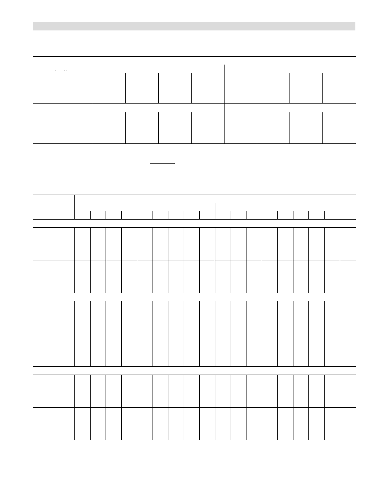
BLOWER DATA
ADJUST"
Stc
Positions
G61MPV−60D−135 BLOWER PERFORMANCE (less filter)
Single Side Return Air − Air volumes in bold require field fabricated transition to accommodate 20 x 25 x 1 in. cleanable air filter in
order to maintain proper air velocity across the filter.
0 through 0.80 in. w.g. External Static Pressure Range
Switch
Positions
"
Second Stage HEAT" Speed − cfm Second Stage COOL" Speed − cfm
1
1
2 3 4 1 2 3
+ 1470 1650 1845 2040 1585 1705 1905 2130
1
NORM 1325 1495 1680 1865 1430 1545 1765 1975
N/A 1335 1505 1670 1275 1370 1565 1755
ADJUST"
Switch
Positions
First Stage HEAT" Speed − cfm First Stage COOL" Speed − cfm
1
1
2 3 4 1 2 3
+ 1335 1510 1695 1870 1105 1180 1330 1500
1
NORM 1210 1370 1540 1710 990 1075 1210 1355
N/A 1225 1375 1515 890 950 1085 1210
1
Factory default jumper setting.
N/A − First and second stage HEAT positions shown cannot be used on this model.
NOTES − The effect of static pressure is included in air volumes shown.
First stage HEAT is approximately 91% of the same second stage
First stage COOL (two−stage air conditioning units only) is approximately 70% of the same second stage COOL speed position.
Continuous Fan Only speed is approximately 38% of the same second stage COOL speed position − minimum 500 cfm.
Lennox Harmony IIIt Zone Control Applications − Minimum blower speed is 470 cfm.
G61MPV−60D−135 BLOWER MOTOR WATTS
Motor Watts @ Various External Static Pressures − in. wg.
Jumper Speed
First Stage Second Stage
0 0.1 0.2 0.3 0.4 0.5 0.6 0.7 0.8 0 0.1 0.2 0.3 0.4 0.5 0.6 0.7 0.8
+" (Plus) SETTING (Adjust" Jumper at +" Setting)
HEAT"
Speed
COOL"
Speed
150 175 210 240 270 300 330 360 390 180 215 255 295 330 365 400 430 465
Tap 1
205
Tap 2
Tap 3
Tap 4
Tap 1
Tap 2
Tap 3
Tap 4
235 275 310 355 395 430 465 500 275 315 360 400 435 470 510 550 585
345 385 420 460 495 535 570 610 415 450 490 525 565 600 640 675 715
315
430 460 495 530 575 620 665 705 750 535 585 640 695 730 765 810 860 905
90 11 0 140 170 195 220 240 265 290 230 265 310 355 390 425 460 490 525
105
130 165 195 215 235 260 290 315 285 330 380 430 455 485 525 565 605
175 205 235 270 300 330 360 385 425 465 515 560 605 645 685 730 770
150
230 270 305 340 375 410 445 480 605 650 695 740 800 855 900 945 985
195
NORM" (Normal) SETTING (Adjust" Jumper at NORM" Setting)
HEAT"
Speed
COOL"
Speed
120 140 170 200 225 255 280 305 330 150 175 210 240 270 300 335 365 400
Tap 1
155
Tap 2
Tap 3
Tap 4
Tap 1
Tap 2
Tap 3
Tap 4
185 220 255 295 335 365 395 425 205 240 275 315 350 385 422 460 495
235
265 300 330 370 405 440 470 500 290 330 380 430 460 485 515 545 575
320 355 390 430 465 505 540 575 610 395 440 485 530 575 620 660 700 740
70 90 11 5 135 165 190 210 230 245 170 200 235 265 305 345 380 420 455
80
100 130 160 185 210 230 255 275 245 270 305 335 370 410 440 470 505
120 140 170 195 225 255 280 305 330 350 385 420 455 495 530 570 610 645
145
175 215 250 280 315 345 375 410 455 500 555 605 645 680 725 770 810
−" (Minus) SETTING (Adjust" Jumper at −" Setting)
HEAT"
Speed
COOL"
Speed
N/A N/A N/A N/A N/A N/A N/A N/A N/A N/A N/A N/A N/A N/A N/A N/A N/A N/A
Tap 1
125
Tap 2
Tap 3
Tap 4
Tap 1
Tap 2
Tap 3
Tap 4
150 175 195 230 265 290 310 335 150 175 210 240 255 290 330 370 405
155 185 215 250 285 320 355 385 420 205 235 270 305 345 380 420 455 490
205
240 285 325 355 385 420 460 495 290 325 360 400 440 480 515 545 580
60 75 95 115 135 150 175 195 220 140 160 185 205 240 280 305 335 360
60
75 100 125 150 175 195 215 235 145 180 215 250 290 325 355 385 420
90 11 0 140 165 190 215 235 255 270 230 265 305 345 380 420 450 480 510
120 140 170 195 225 255 275 300 325 330 365 405 445 485 525 560 595 635
Speed Switch Positions
HEAT speed position.
1
4
1
4
Page 21
Page 22
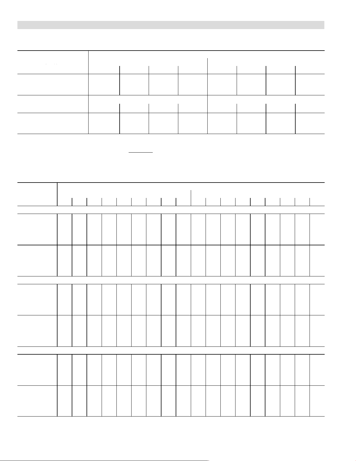
BLOWER DATA
ADJUST"
Stc
Positions
G61MPV−60D−135 BLOWER PERFORMANCE (less filter)
Side Return Air with Optional RAB Return Air Base
0 through 0.80 in. w.g. External Static Pressure Range
Switch
Positions
1
ADJUST"
Switch
Positions
1
1
Factory default jumper setting.
N/A − First and second stage HEAT positions shown cannot be used on this model.
NOTES − The effect of static pressure is included in air volumes shown.
First stage HEAT is approximately 91% of the same second stage
First stage COOL (two−stage air conditioning units only) is approximately 70% of the same second stage COOL speed position.
Continuous Fan Only speed is approximately 38% of the same second stage COOL speed position − minimum 500 cfm.
Lennox Harmony IIIt Zone Control Applications − Minimum blower speed is 470 cfm.
G61MPV−60D−135 BLOWER MOTOR WATTS
Jumper Speed
+" (Plus) SETTING (Adjust" Jumper at +" Setting)
HEAT"
Speed
Tap 1
Tap 2
Tap 3
Tap 4
COOL"
Speed
Tap 1
Tap 2
Tap 3
Tap 4
NORM" (Normal) SETTING (Adjust" Jumper at NORM" Setting)
HEAT"
Speed
Tap 1
Tap 2
Tap 3
Tap 4
COOL"
Speed
Tap 1
Tap 2
Tap 3
Tap 4
−" (Minus) SETTING (Adjust" Jumper at −" Setting)
HEAT"
Speed
Tap 1
Tap 2
Tap 3
Tap 4
COOL"
Speed
Tap 1
Tap 2
Tap 3
Tap 4
"
Second Stage HEAT" Speed − cfm Second Stage COOL" Speed − cfm
1
2 3 4 1 2 3
1
+ 1445 1635 1825 2025 1550 1660 1875 2105
NORM 1305 1475 1660 1840 1400 1510 1720 1920
N/A 1315 1480 1650 1250 1345 1530 1715
First Stage HEAT" Speed − cfm First Stage COOL" Speed − cfm
1
1
2 3 4 1 2 3
+ 1315 1490 1675 1855 1080 1155 1310 1478
NORM 1195 1365 1530 1695 985 1055 1190 1325
N/A 1210 1360 1500 875 945 1060 1190
HEAT speed position.
Motor Watts @ Various External Static Pressures − in. wg.
First Stage Second Stage
0 0.1 0.2 0.3 0.4 0.5 0.6 0.7 0.8 0 0.1 0.2 0.3 0.4 0.5 0.6 0.7 0.8
145 175 205 235 265 295 325 355 385 195 225 260 290 330 370 400 435 470
205
235 270 305 340 375 415 450 485 275 310 355 400 430 460 495 535 570
285 325 370 410 450 490 525 565 600 420 445 470 495 545 590 630 675 715
385 430 480 530 570 610 650 690 725 535 580 625 670 710 755 800 845 890
90 11 0 140 165 190 210 235 260 285 235 265 305 340 380 415 450 480 515
105
130 160 190 210 230 255 285 310 290 325 370 410 450 490 515 545 575
170 205 235 265 290 325 355 390 420 460 510 555 595 640 680 715 755
145
200 230 270 305 345 385 415 445 480 580 630 690 745 800 850 895 935 975
130 150 170 190 225 260 285 305 330 150 175 205 235 265 295 325 355 385
160
190 225 260 290 325 355 390 420 200 230 265 300 345 385 410 440 465
235
265 300 335 370 400 435 470 500 290 330 375 415 450 485 515 540 570
310 350 390 435 470 500 540 575 610 405 440 485 525 560 590 635 680 725
70 90 11 5 140 165 190 210 230 250 170 200 235 270 305 335 370 400 430
90
105 125 150 175 200 225 250 270 200 230 270 310 355 400 435 465 495
115 140 170 195 225 250 275 300 325 330 365 400 440 485 525 555 585 615
145
175 205 240 270 295 330 365 395 435 480 530 580 625 675 715 750 790
N/A N/A N/A N/A N/A N/A N/A N/A N/A N/A N/A N/A N/A N/A N/A N/A N/A N/A
125
145 170 195 225 255 280 300 325 150 175 210 240 265 290 325 365 400
190 220 250 285 320 350 380 410 200 230 270 305 350 395 420 445 475
160
235 275 310 355 395 425 460 490 285 320 355 395 435 475 510 545 580
200
60 75 95 115 135 155 175 195 215 135 155 180 205 240 280 305 330 355
70
90 11 0 130 150 170 195 215 235 160 185 215 240 275 310 345 375 410
85 105 130 155 180 205 230 250 270 220 255 295 335 370 410 440 475 510
120 140 170 195 220 240 270 295 325 330 365 400 440 480 525 555 585 615
Speed Switch Positions
1
4
1
4
Page 22
Page 23
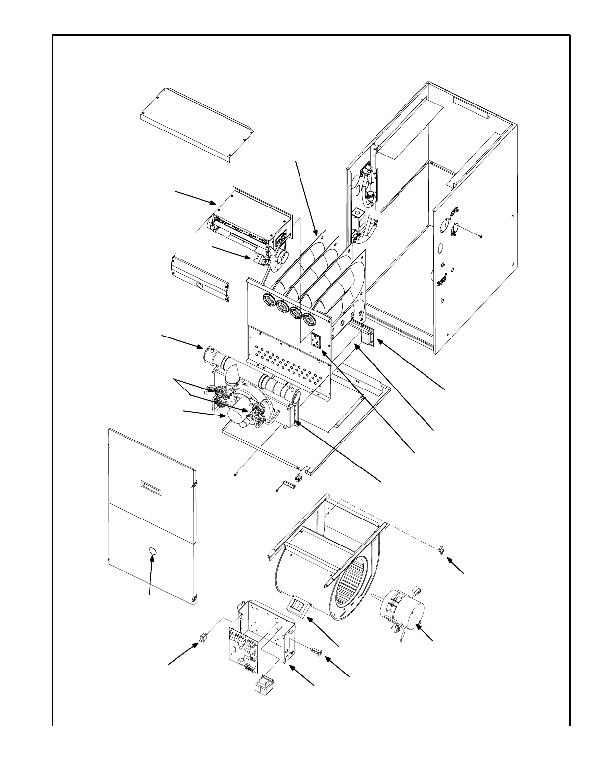
BURNER BOX
ASSEMBLY
GAS VALVE
AND MANIFOLD
FLUE
COLLAR
TOP CAP
G61MPV PARTS ARRANGEMENT
DuralokPlus
HEAT EXCHANGER
ASSEMBLY
TM
CABINET
COMBUSTION
AIR PRESSURE PROVE
SWITCHES
(36B−045 has 2 single switches)
COMBUSTION AIR
INDUCER
BURNER
ACCESS
PANEL
BLOWER
ACCESS
PANEL
SIGHT
GLASS
WARM HEADER
(COLLECTOR)
BOX
CONDENSER COIL
PRIMARY LIMIT
COLD HEADER
(COLLECTOR)
BOX
SECONDARY
LIMITS (2)
DOOR
INTERLOCK
SWITCH
CONTROL BOX
FIGURE 1
Page 23
Power Choke
(5 Ton Only)
CIRCUIT BREAKER
Blower Motor
Page 24
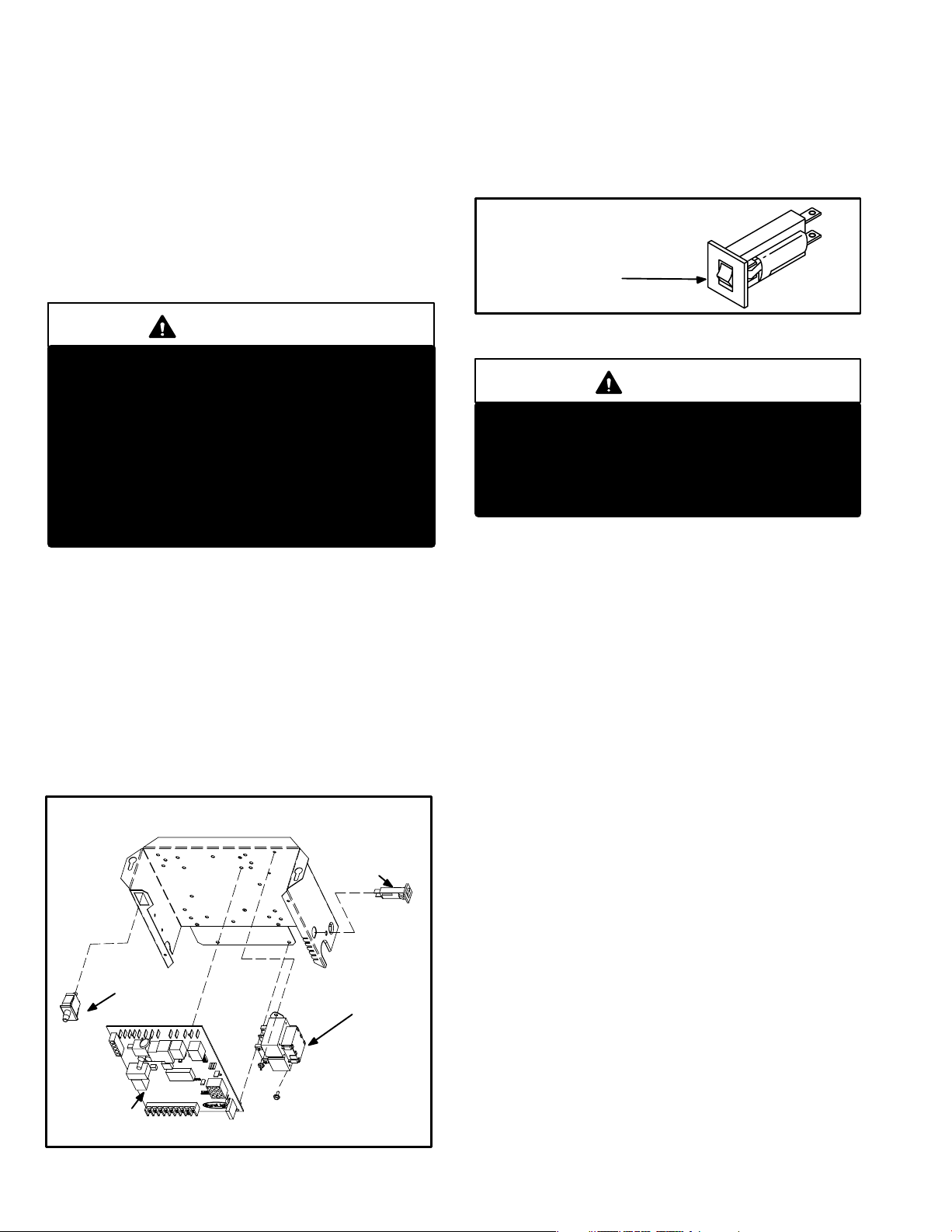
I−UNIT COMPONENTS
G61MPV unit components are shown in figure 1. The gas
valve, combustion air inducer and burners can be accessed by removing the burner access panel. Electrical
components are in the control box (figure 2) found in the
blower section.
G61MPV units are factory equipped with a bottom return air
panel in place. The panel is designed to be field removed as
required for bottom air return. Markings are provided for side
return air and may be cut out in the field.
3. Circuit Breaker (CB8)
A 24V circuit breaker is also located in the control box.
The switch provides overcurrent protection to the transformer (T1). The breaker is rated 3A at 32V. If the current
exceeds this limit the breaker will trip and all unit operation will shutdown. The breaker can be manually reset
by pressing the button on the face. See figure 3.
CIRCUIT BREAKER CB8
ELECTROSTATIC DISCHARGE (ESD)
Precautions and Procedures
CAUTION
Electrostatic discharge can affect electronic
components. Take precautions during furnace
installation and service to protect the furnace’s
electronic controls. Precautions will help to avoid
control exposure to electrostatic discharge by
putting the furnace, the control and the technician at the same electrostatic potential. Neutralize electrostatic charge by touching hand and all
tools on an unpainted unit surface, such as the
gas valve or blower deck, before performing any
service procedure.
A−Control Box
1. Control Transformer (T1)
A transformer located in the control box provides power to
the low voltage section of the unit. Transformers on all
models are rated 40VA with a 120V primary and a 24V secondary.
2. Door Interlock Switch (S51)
A door interlock switch rated 14A at 125VAC is wired in series with line voltage. When the blower door is removed the
unit will shut down.
CONTROL BOX G61MPV
PRESS TO RESET
FIGURE 3
WARNING
Shock hazard.
Disconnect power before servicing. Integrated
Control Board is not field repairable. If control is
inoperable, simply replace entire control.
Can cause injury or death. Unsafe operation will
result if repair is attempted.
4. Integrated Control Board (A92)
SureLight Board 49M59
G61MPV units are equipped with the Lennox two−stage,
variable speed integrated SureLight® control. The system consists of a ignition / blower control (figure 4 with
control terminal designations in tables 1 through 4) and ignitor (figure 12). The control and ignitor work in combination to ensure furnace ignition and ignitor durability. The
SureLight integrated board controls all major furnace operations. The control features two LED lights, (DS1 and
DS2) for troubleshooting and four LED lights (DS3, DS6,
DS7 and DS8) to show furnace status. The control also
has two accessory terminals rated at (1) one amp each.
See table 5 for status code and table 6 for troubleshooting
diagnostic codes.
DOOR INTERLOCK
SURELIGHT®
CONTROL
BOARD
SWITCH
FIGURE 2
CIRCUIT
BREAKER
TRANSFORMER
Electronic Ignition
At the beginning of the heat cycle the SureLight control
monitors the first stage and second stage combustion air
inducer prove switch. The control will not begin the heating
cycle if the first stage or second stage prove switch is
closed (jumpered). Likewise the control will not begin the
second stage heating cycle if the second stage prove
switch is closed, and will remain in first stage heat. However, if the second stage prove switch closes during the first
stage heat pre−purge, the control will allow second stage
heat. Once the first stage prove switch is determined to be
open, the combustion air inducer is energized on low (first
stage) heat speed. When the differential in the prove switch
is great enough, the prove switch closes and a 15−second
pre−purge begins. If the switch is not proven within 2−1/2
minutes, the control goes into Watchguard−Pressure
Switch mode for a 5−minute re−set period.
Page 24
Page 25
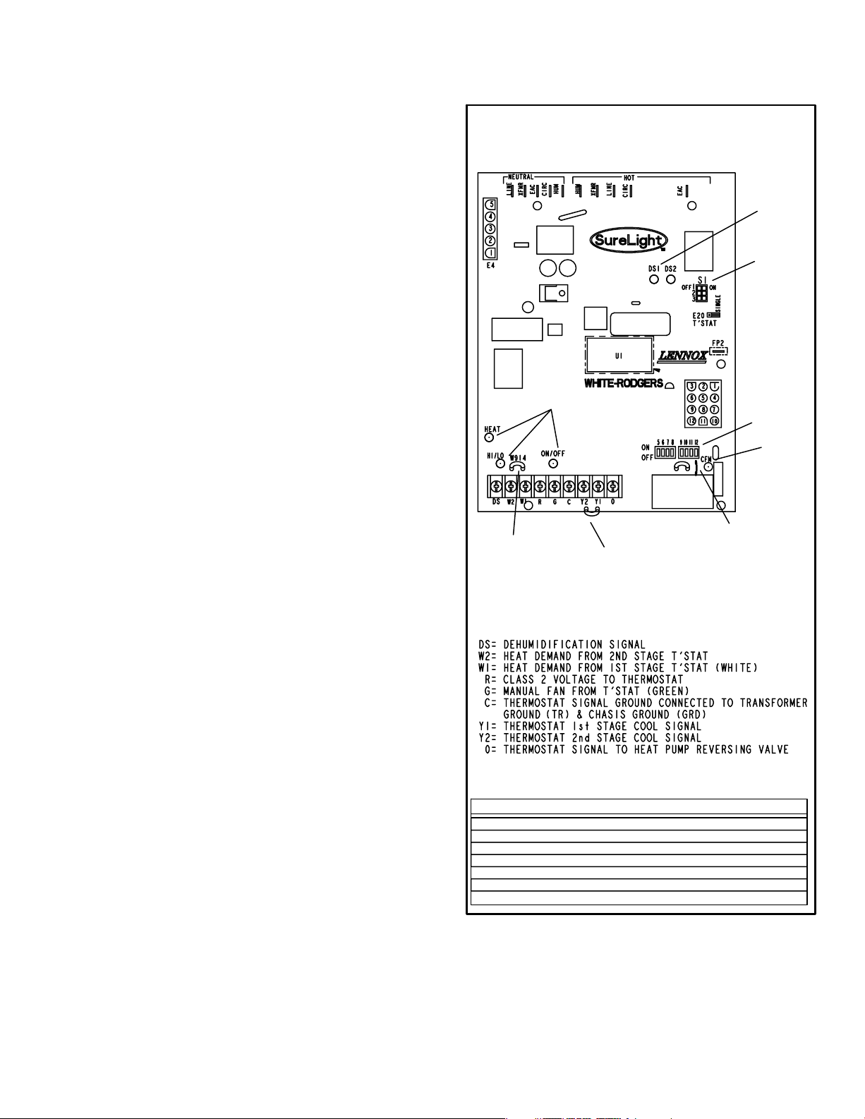
After the 15−second pre−purge period, the SureLight ignitor
warms up for 20 seconds after which the gas valve opens
for a 4−second trial for ignition. The ignitor energizes during
the trial until flame is sensed. If ignition is not proved during
the 4−second period, the control will try four more times with
an inter−purge and warm−up time between trials of 35 seconds. After a total of five trials for ignition (including the initial trial), the control goes into Watchguard mode. After a
60−minute reset period, the control will begin the ignition
sequence again.
The SureLight control has an added feature that prolongs
the life of the ignitor. After a successful ignition, the SureLight control utilizes less power to energize the ignitor on
successive calls for heat. The control continues to ramp
down the voltage to the ignitor until it finds the lowest
amount of power that will provide a successful ignition. This
amount of power is used for 255 cycles. On the 256th call
for heat, the control will again ramp down until the lowest
power is determined and the cycle begins again.
Two Stage Operation / Thermostat Selection Jumper
TWO−STAGE, VARIABLE SPEED INTEGRATED
CONTROL BOARD
DIAGNOSTIC
LEDs
DIP
SWITCHES
1 − 3
LEDs
DIP
SWITCHES
5 − 12
LED
The control can be utilized in two modes: SINGLE−STAGE
thermostat or TWO−STAGE thermostat. The thermostat
selection jumper E20, located just below dip switches 1
through 3 (figure 4), must be positioned for the particular
application. The jumper is factory set on TWO" for use
with a two−stage thermostat with two stage heat. Re−position jumper to SINGLE" for use with a single stage thermostat with two stage heat.
While in the single−stage thermostat mode (single jumper
setting), the burners will always fire on first−stage heat. The
combustion air inducer will operate on low speed and indoor blower will operate on low heat speed. After a 10 minute recognition period, the unit will switch to second stage
heat. While in the two−stage thermostat mode (two jumper
setting) the burners will fire on first−stage heat. The combustion air inducer will operate on low speed and indoor
blower will operate on low heat speed. The unit will switch
to second−stage heat on call from the indoor thermostat. If
there is a simultaneous call for first and second stage heat,
the unit will fire an first stage heat and switch to second
stage heat after 30 seconds of operation. See Sequence of
Operation flow charts in the back of this manual for more
detail.
ON−BOARD
JUMPER W914
(cut when SignatureStat,
CCB1 or Harmony II are
used)
ON−BOARD
JUMPER W915
(cut when two−stage
cooling is used)
JUMPER W951
(cut when heat pump is
used with FM21)
THERMOSTAT CONNECTIONS (TB1)
DIP SWITCH FUNCTIONS
DIP SWITCH(ES) FUNCTION
1 and 2 Blower Off Delay
3 Second Stage ON Delay (Single−stage t’stat)
4 Not used
5 and 6 Cooling Mode Blower Speed
7 and 8 Blower Speed Adjustment
9 and 10 Cooling Mode Blower Ramping Profile
11 and 12 Heating Mode Blower Speed
FIGURE 4
ON−BOARD
Page 25
Page 26
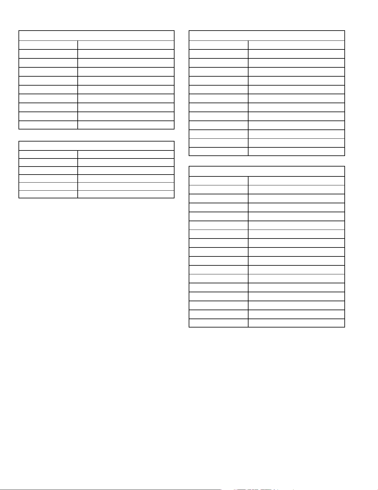
TABLE 1
SureLight Control / Blower Control Terminals
LINE Line 120VAC Neutral
XFMR Transformer 120VAC Neutral
EAC Electronic Air Cleaner 120VAC Neutral
CIRC Indoor Blower 120VAC Neutral
HUM Humidifier 120VAC Neutral
HUM Humidifier 120VAC Hot
XMFR Transformer 120VAC Hot
LINE Line 120VAC Hot
CIRC Indoor Blower 120VAC Hot
EAC Electronic Air Cleaner 120VAC Hot
TABLE 2
SureLight Control 5 Pin Terminal Designation
PIN # Function
1 Ignitor
2 Combustion Air Inducer High Speed
3 Combustion Air Inducer Low Speed
4 Combustion Air Inducer Neutral
5 Ignitor Neutral
TABLE 3
SureLight Control 12Pin Terminal Designation
PIN # Function
1 Gas Valve High Fire
2 Second Stage Pressure Switch
3 Not Used
4 Ground
5 24V Hot
6 Primary Limit In
7 Gas Valve Low Stage
8 Gas Valve Common
9 24V Neutral
10 Ground
11 Primary Limit Out
12 1st Stage Pressure Switch
TABLE 4
SureLight Control 16 Pin Blower Control Terminals
PIN # Function
1 Ground
2 Low Heat Speed
3 Ground
4 DELAY" Dip Switch Selection
5 COOL" Dip Switch Selection
6 Y1" Signal
7 ADJUST" Dip Switch Selection
8 Ground
9 0" From Thermostat
10 DS" Output Signal
11 HEAT" Dip Switch Selection
12 24 VAC
13 HIGH HEAT Speed
14 Y2" Signal
15 G"
16 CFM LED
Page 26
Page 27
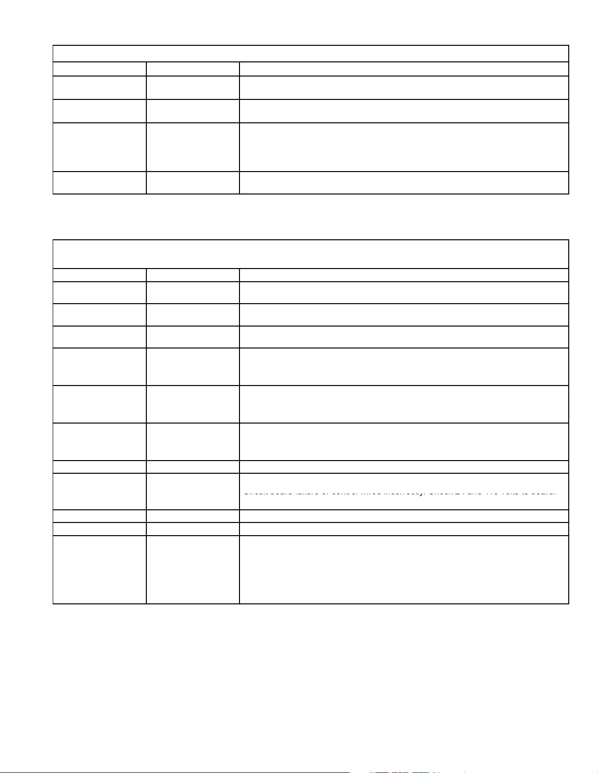
TABLE 5
ONONON
Circuit board failure or control wired incorrectly. Check 24 and 115 volts to board.
STATUS CODES
STATUS LED COLOR FUNCTION
DS3
ON / OFF ’
DS6
CFM"
DS7
HI / LO"
DS8
HEAT"
GREEN
GREEN
YELLOW
YELLOW DS8−ON indicates the system is in HEAT mode.
DS3−ON indicates that the motor has a demand to operate. (This LED must be on in all
modes).
DS6−blinking indicates the airflow (CFM) demand in the motor. The air flow is determine by
counting blinks between two (2) second pauses. One blink equals approximatley 100 CFM.
DS7−ON indicaties the DS to R" jumper has not been cut. When the jumper is cut the system
will be operating with LENNOX HARMONY IIt (See Harmony Installation Instructions) or
with the CCB1 Efficiency Plus control.
CCB1: When ON, a 24 VAC is being applied and when OFF, it has been removed. This on/off
operation varies the indoor blower’s performance so dehumidification can be enhanced.
TABLE 6
DIAGNOSTIC CODES
Diagnostic LEDs are labeled DS1 and DS2. See figure 4 for location of diagnostic LEDs.
DS1 DS2 DESCRIPTION
SIMULTANEOUS
SLOW FLASH
SIMULTANEOUS
FAST FLASH
SLOW FLASH ON
OFF SLOW FLASH
OFF FAST FLASH
ALTERNATING
SLOW FLASH
SLOW FLASH OFF Flame sensed without gas valve energized.
ON ON
OFF ON
FAST FLASH SLOW FLASH Main power polarity reversed. Switch line and neutral.
SLOW FLASH FAST FLASH Low flame signal. Measures below 0.23 microAmps. Replace flame sense rod.
ALTERNATING
FAST FLASH
SIMULTANEOUS
SLOW FLASH
SIMULTANEOUS
FAST FLASH
ALTERNATING
SLOW FLASH
OFF
ALTERNATING
FAST FLASH
Power on − Normal operation.
Also signaled during cooling and continuous fan.
Normal operation − signaled when heating demand initiated at thermostat.
Primary, secondary, backup secondary or rollout limit switch open. Limits must
close within 3 minutes or unit goes into 1 hour Watchguard.
Low prove switch open;
OR: Blocked inlet/exhaust vent;
OR: Low prove switch closed prior to activation of combustion air inducer.
High prove switch open;
OR: Blocked inlet/exhaust vent;
OR: High prove switch closed prior to activation of combustion air inducer.
Watchguard −− burners failed to ignite; OR limit open more than 3 minutes;
OR lost flame sense 5 times in one heating cycle;
OR pressure switch opened 5 times in one heating cycle.
Circuit board failure or control wired incorrectly. Check 24 and 115 volts to board.
The following conditions are sensed during the ignitor warm−up period only:
1) Improper main ground;
2) Broken ignitor; OR: Open ignitor circuit;
3) Line voltage below 75 volts.
(If voltage lower than 75 volts prior to ignitor warm-up, control will signal waiting on
call from thermostat, and will not respond.
NOTE − Slow flash rate equals 1 Hz (one flash per second). Fast flash rate equals 3 Hz (three flashes per second).
Low flame sense current = 0.17−0.22 microAmps.
Page 27
Page 28
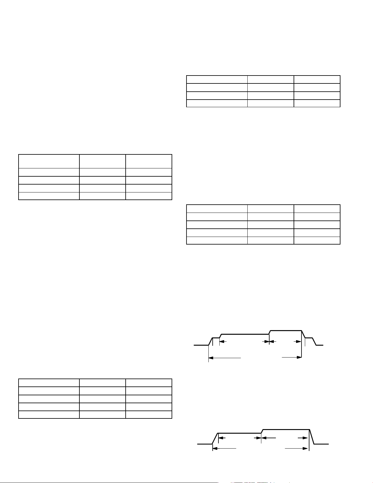
Dip Switch Settings
Switches 1 and 2 −− Blower Off Delay −− The blower−on
delay of 45 seconds is not adjustable. The blower−off delay
(time that the blower operates after the heating demand
has been satisfied) can be adjusted by moving switches 1
and 2 on the integrated control board. The unit is shipped
from the factory with a blower−off delay of 90 seconds. The
blower off delay affects comfort and is adjustable to satisfy
individual applications. Adjust the blower off delay to
achieve a high fire supply air temperature between 90° and
110°F at the exact moment that the blower is de−energized.
Longer off delay settings provide lower supply air temperatures; shorter settings provide higher supply air temperatures. The table below provides the blower off timings that
will result from different switch settings.
TABLE 7
Blower Off Delay Switch Settings
Blower Off Delay
(Seconds)
Switch 1 Switch 2
60 Off Off
90 Off On
120 On Off
180 On On
Switch 3 −− Second Stage Delay (Used with Single−
Stage Thermostat Only) −− This switch is used to deter-
mine the second stage on delay when a single−stage thermostat is being used. The switch is factory−set in the ON
position, which provides a 10−minute delay before second−
stage heat is initiated. If the switch is toggled to the OFF
position, it will provide a 15−minute delay before second−
stage heat is initiated. This switch is only activated when
the E20 thermostat selector jumper is positioned for
SINGLE−stage thermostat use.
Switch 4 −− Not used in G61MPV application.
Switches 5 and 6 −− Cooling Mode Blower Speed −−
Switches 5 and 6 are used to select second stage cooling
blower motor speed (first stage cooling speed is 70% of
second stage). The unit is shipped from the factory with the
dip switches positioned for high speed (4) indoor blower
motor operation during the cooling mode. The table below
provides the cooling mode blower speeds that will result
from different switch settings. Refer to blower data tables at
the front of this manual for corresponding cfm values.
TABLE 8
Cooling Mode Blower Speeds
Speed
Switch 5 Switch 6
1 − Low On On
2 − Medium Low Off On
3 − Medium High On Off
4 − High (Factory) Off Off
Switches 7 and 8 −− Blower Speed Adjustment −−
Switches 7 and 8 are used to select blower speed adjustment settings. The unit is shipped from the factory with the
dip switches positioned for NORMAL (no) adjustment. The
dip switches may be positioned to adjust the blower speed
by +10% or −10% to better suit the application. The table
below provides blower speed adjustments that will result
from different switch settings. Refer to blower data tables at
the front of this manual for corresponding cfm values.
TABLE 9
Blower Speed Adjustment
Adjustment
Switch 7 Switch 8
+10% (approx.) On Off
NORMAL (Factory) Off Off
−10% (approx.) Off On
Switches 9 and 10 −− Cooling Mode Blower Speed
Ramping −− Switches 9 and 10 are used to select cooling
mode blower speed ramping options. Blower speed ramping may be used to enhance dehumidification performance. The switches are factory set at option A which has
the greatest effect on blower motor performance. The table
below provides the cooling mode blower speed ramping
options that will result from different switch settings. The
cooling mode blower speed ramping options are detailed
below.
TABLE 10
Cooling Mode Blower Speed Ramping
Ramping Option
Switch 9 Switch 10
A (Factory) Off Off
B On Off
C Off On
D On On
COOLING MODE RAMPING OPTIONS
Ramping Option A (Factory Selection)
S Motor runs at 50% for 30 seconds.
S Motor then runs at 82% for approximately 7−1/2 min-
utes. If demand has not been satisfied after 7−1/2 minutes, motor runs at 100% until demand is satisfied.
S Once demand is met, motor runs at 50% for 30 sec-
onds then ramps down to stop.
OFF
1/2 MIN
50% CFM
7 1/2 MIN
82% CFM
COOLING DEMAND
Ramping Option B
S Motor runs at 82% for approximately 7−1/2 minutes. If
demand has not been satisfied after 7−1/2 minutes,
motor runs at 100% until demand is satisfied.
S Once demand is met, motor ramps down to stop.
7 1/2 MIN
OFF
82%CFM
COOLING DEMAND
100%
CFM
100% CFM
1/2 MIN
50% CFM
OFF
OFF
Page 28
Page 29
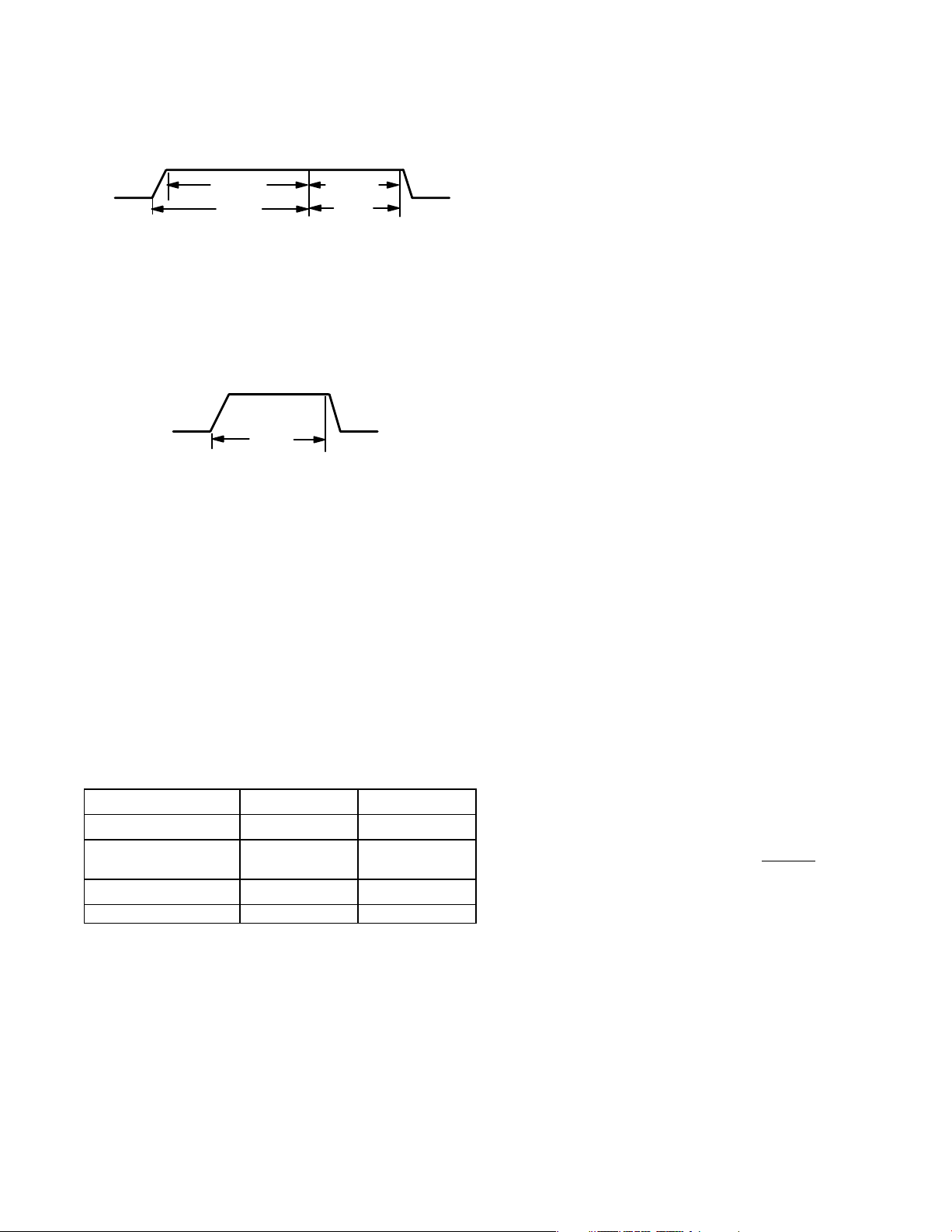
Ramping Option C
S Motor runs at 100% until demand is satisfied.
S Once demand is met, motor runs at 100% for 60 sec-
onds then ramps down to stop.
OFF
100% CFM
DEMAND
100% CFM
60 SEC.
OFF
Ramping Option D
S Motor runs at 100% until demand is satisfied.
S Once demand is met, motor ramps down to stop.
100% CFM
COOLING
DEMAND
OFFOFF
Switches 11 and 12 −− Heating Mode Blower Speed −−
Switches 11 and 12 are used to select second stage heat-
ing mode blower motor speed (first stage heating blower
speed is 91% of second stage). The unit is shipped from the
factory with the dip switches positioned for medium low (2)
speed indoor blower motor operation during the heating
mode. The table below provides the heating mode blower
speeds that will result from different switch settings. Refer
to blower data tables at the front of this manual for corre-
sponding cfm values.
TABLE 11
Heating Mode Blower Speeds
Speed
Switch 11 Switch 12
1 − Low On On
2 − Medium Low
(Factory)
Off On
3 − Medium High On Off
4 − High Off Off
On−Board Jumper W914
On−board jumper W914, which connects terminals DS and
R on the integrated control board, must be cut when the furnace is installed with the Harmony II zone control board,
the CCB1 EfficiencyPlus humidity control or the Lennox
SignatureStat.t If the jumper is left intact the PMW signal
from the Harmony II control will be blocked and also lead to
control damage. The SignatureStat and CCB1 will not operate unless the jumper is cut. Refer to table 21 for operation sequence in applications including a G61MPV, CCB1
and single−speed outdoor unit. Table 22 gives the operation sequence in applications with a two−speed outdoor
unit. See table 23 for applications for a G61MVP, SignatureStat and single−speed outdoor unit and table 24 for applications with a two−speed outdoor unit.
On−Board Jumper W951
On−board jumper W951, which connects terminals R and O
on the integrated control board, must be cut when the furnace is installed in applications which include a heat pump
unit and the FM21 FuelMaster control board. If the jumper
is left intact, terminal "O" will remain energized eliminating
the HEAT MODE in the heat pump.
On−Board Jumper W915
On−board jumper W915, which connects terminals Y1 and
Y2 on the integrated control board, must be cut if two−stage
cooling will be used. If the jumper is not cut the outdoor unit
will operate in first−stage cooling only.
Diagnostic LEDs (DS1 and DS2)
Two diagnostic LEDs are located on the two−stage, variable speed integrated control just to the left of the first bank
of dip switches. These flashing lights correspond with diagnostic codes detailed on page 52.
Status LEDs (HEAT, HI/LO, ON/OFF and CFM)
The integrated control includes four LEDs which indicate
operating status. The green ON/OFF LED is lit any time the
blower is operating. The green CFM LED indicates the
blower motor speed. Count the number of blinks between
the two−second pauses to determine the CFM. Each blink
represents approximately 100 CFM. The yellow HI/LO LED
is lit when the W914 (DS to R) jumper has not
been clipped
for SignatuteStat, CCB1 or Harmony operation. The yellow
HEAT LED is lit when the indoor blower is operating at the
HEATING speed.
Page 29
Page 30

WARNING
Shock hazard.
Disconnect power before servicing. Integrated
Control Board is not field repairable. If control is
inoperable, simply replace entire control.
Can cause injury or death. Unsafe operation will
result if repair is attempted.
5. Integrated Control Board(A92)
SureLight Board 100870
G61MPV −7 and later units are equipped with the Lennox
two−stage, variable speed integrated SureLight control
board. The system consists of a ignition / blower control
board (figures 5 and 6) with control pin designations in
tables 12, 13 and 14 and ignitor (figure 13). The board and
ignitor work in combination to ensure furnace ignition and
ignitor durability. The SureLight integrated board controls
all major furnace operations. The board features a red LED
light, for furnace status and troubleshooting. The LED
flashes in X" + Y" codes. For example using table 15 under PRESSURE SWITCH CODES", if the red LED
flashes 2 times, then off for 2 seconds then flashes 3
times, the low pressure switch is failed open. Two green
LEDs show indoor blower status and CFM. See Page 35
for more detail. The board also has two 120 volt accessory terminals rated at (1) one amp each. In addition there is
a 24 volt accessory terminal located on TB1.
Electronic Ignition
At the beginning of the heat cycle the SureLight control
monitors the first stage and second stage combustion air
inducer prove switch. The control will not begin the heating
cycle if the first stage prove switch is closed (by−passed).
Likewise the control will not begin the second stage heating
cycle if the second stage prove switch is closed, and will remain in first stage heat. However, if the second stage prove
switch closes during the first stage heat pre−purge, the control will allow second stage heat. Once the first stage prove
switch is determined to be open, the combustion air inducer is energized on low (first stage) heat speed. When the
differential in the prove switch is great enough, the prove
switch closes and a 15−second pre−purge begins. If the
switch is not proven within 2−1/2 minutes, the control goes
into Watchguard−Pressure Switch mode for a 5−minute re−
set period.
After the 15−second pre−purge period, the SureLight ignitor
warms up for 20 seconds after which the gas valve opens
for a 4−second trial for ignition. The ignitor energizes during
the trial until flame is sensed. If ignition is not proved during
the 4−second period, the control will try four more times with
an inter purge and warm−up time between trials of 35 seconds. After a total of five trials for ignition (including the initial trial), the control goes into Watchguard−Flame Failure
mode. After a 60−minute reset period, the control will begin
the ignition sequence again.
NOTE − Board 100870 provides a regulated 95 volts
the ignitor.
Two Stage Operation / Thermostat Selection Jumper
The control can be utilized in two modes: SINGLE−STAGE
thermostat or TWO−STAGE thermostat. The thermostat
selection is made using a dip switch (figure 4) and must be
positioned for the particular application. The dip switch is
factory set on TWO" for use with a two−stage thermostat
with two stage heat. Re−position dip switch to SINGLE" for
use with a single stage thermostat with two stage heat.
While in the single−stage thermostat mode (single dip
switch setting), the burners will always fire on first−stage
heat. The combustion air inducer will operate on low speed
and indoor blower will operate on low heat speed. After a
factory default 10 minute recognition period, the unit will
switch to second stage heat. While in the two−stage thermostat mode (two dip switch setting) the burners will fire on
first−stage heat. The combustion air inducer will operate on
low speed and indoor blower will operate on low heat
speed. The unit will switch to second−stage heat on call
from the indoor thermostat. If there is a simultaneous call
for first and second stage heat, the unit will fire an first stage
heat and switch to second stage heat after 30 seconds of
operation. See Sequence of Operation flow charts in the
back of this manual for more detail.
Page 30
Page 31

TWO−STAGE, VARIABLE SPEED INTEGRATED CONTROL BOARD
1/4" QUICK CONNECT TERMINALS
NEUTRALS= 120 VAC NEUTRAL
ON
1
ON
12
DIAGNOSTIC
LEDs
4
HEATING
DIP
SWITCHES
FUTURE USE
1
5
9
16
8
INDOOR
BLOWER DIP
SWITCHES
H= 24V HUMIDIFIER OUTPUT
ON−BOARD
JUMPERS
L= LENNOX SYSTEM OPERATION MONITOR
1= FUTURE USE
THERMOSTAT CONNECTIONS (TB1)
DIP SWITCH FUNCTIONS
HTG DIP SWITCH(ES) FUNCTION
1 T’stat Heat Stages (single or two−stage)
W915
W951
W914
INDOOR BLOWER
2 Second Stage ON Delay (single−stage t’stat)
3 and 4 Heating Fan OFF Delay
FUNCTION
DIP SWITCH(ES)
5 and 6 Cooling Mode Blower Speed
7 and 8 Blower Speed Adjustment
9 and 10 Cooling Mode Blower Ramping Profile
11 and 12 Heating Mode Blower Speed
FIGURE 5
TABLE 12
SureLight Board 5 Pin Terminal Designation
PIN # Function
1 Ignitor
2 Combustion Air Inducer High Speed
3 Combustion Air Inducer Low Speed
4 Combustion Air Inducer Neutral
5 Ignitor Neutral
TABLE 13
SureLight Board 12Pin Terminal Designation
PIN # Function
1 Gas Valve High Fire
2 Second Stage Prove Switch
3 Rollout In
4 Ground
5 24V Hot
6 Primary Limit In
7 Gas Valve Low Stage
8 Gas Valve Common
9 24V Neutral
10 Ground
11 Rollout Switch Out
12 1st Stage Prove Switch
TABLE 14
SureLight Board 16 Pin Blower Control Terminals
PIN # Function
1 Ground
2 Low Heat Speed
3 Ground
4 DELAY" Dip Switch Selection
5 COOL" Dip Switch Selection
6 Y1" Signal
7 ADJUST" Dip Switch Selection
8 Ground
9 0" From Thermostat
10 DS" Output Signal
11 HEAT" Dip Switch Selection
12 24 VAC
13 HIGH HEAT Speed
14 Y2" Signal
15 G"
16 CFM LED
Page 31
Page 32

FIGURE 6
Page 32
Page 33

TABLE 15
FLASH CODE
(X + Y)
STATUS / ERROR DESCRIPTION
FLASH CODE DESCRIPTIONS
Pulse A 1/4 second flash followed by four seconds of off time.
Heartbeat Constant 1/2 second bright and 1/2 second dim cycles.
X + Y
Pulse Power on − Standby.
Heartbeat Normal operation − signaled when heating demand initiated at thermostat.
LED flashes X times at 2Hz, remains off for two seconds, flashes Y times at 2Hz, remains off for four
seconds, then repeats.
FLAME CODES
1 + 2 Low flame current −− run mode.
1 + 3 Flame sensed out of sequence −− flame still present.
PRESSURE SWITCH CODES
2 + 3 Low pressure switch failed open.
2 + 4 Low pressure switch failed closed.
2 + 5 High pressure switch failed open.
2 + 6 High pressure switch failed closed.
2 + 7 Low pressure switch opened during ignition trial or heating demand.
LIMIT CODE
3 + 1 Limit switch open.
WATCHGUARD CODES
4 + 1 Watchguard −− Exceeded maximum number of retries.
4 + 2 Watchguard −− Exceeded maximum number of retries or last retry was due to pressure switch opening.
4 + 3 Watchguard −− Exceeded maximum number of retries or last retry was due to flame failure.
4 + 5 Watchguard −− Limit remained open longer than three minutes.
4 + 6
4 + 7 Ignitor circuit fault −− Failed ignitor or triggering circuitry.
4 + 8 Low line voltage.
Watchguard −− Flame sensed out of sequence; flame signal gone.
HARD LOCKOUT CODES
5 + 1 Hard lockout −− Rollout circuit open or previously opened.
5 + 2 Control failed self check, internal error (control will restart if error recovers).
5 + 3 No Earth ground (control will restart if error recovers).
5 + 4 Reversed line voltage polarity (control will restart if the error recovers).
5 + 6 Low secondary (24VAC) voltage.
Page 33
Page 34

Dip Switch Settings
Heating Operation DIP Switch Settings
Switch 1 −− Thermostat Selection −− This unit may be used
with either a single−stage or two−stage thermostat. The
thermostat selection is made using a DIP switch which
must be properly positioned for the particular application.
The Dip switch is factory−positioned for use with a two−
stage thermostat. If a single−stage thermostat is to be used,
the DIP switch must be repositioned.
a − Select OFF" for two−stage heating operation con-
trolled by a two−stage heating thermostat (factory setting);
b − Select ON" for two−stage heating operation con-
trolled by a single−stage heating thermostat. This setting provides a timed delay before second−stage heat
is initiated.
Switch 2 −− Second Stage Delay (Used with Single−
Stage Thermostat Only) −− This switch is used to deter-
mine the second stage on delay when a single−stage thermostat is being used. The switch is factory−set in the OFF
position, which provides a 10−minute delay before second−
stage heat is initiated. If the switch is toggled to the ON
position, it will provide a 15−minute delay before second−
stage heat is initiated. This switch is only activated when
the thermostat selector jumper is positioned for SINGLE−
stage thermostat use.
operation during the cooling mode. The table below provides the cooling mode blower speeds that will result from
different switch settings. Refer to blower tables at the front
of this manual for corresponding cfm values.
Cooling Mode Blower Speeds
Speed
1 − Low On On
2 − Medium Low Off On
3 − Medium High On Off
4 − High (Factory) Off Off
Switches 7 and 8 −− Blower Speed Adjustment −−
Switches 7 and 8 are used to select blower speed adjustment settings. The unit is shipped from the factory with the
DIP switches positioned for NORMAL (no) adjustment.
The DIP switches may be positioned to adjust the blower
speed by +10% or −10% to better suit the application. The
table below provides blower speed adjustments that will result from different switch settings. Refer to blower tables at
the front of this manual for corresponding cfm values.
Blower Speed Adjustment
Adjustment
+10% (approx.) On Off
NORMAL (Factory) Off Off
−10% (approx.) Off On
TABLE 17
Switch 5 Switch 6
TABLE 18
Switch 7 Switch 8
Switches 3 and 4 −− Blower−Off Delay −− The blower−on
delay of 45 seconds is not adjustable. The blower−off delay
(time that the blower operates after the heating demand
has been satisfied) can be adjusted by moving switches 3
and 4 on the integrated control board. The unit is shipped
from the factory with a blower−off delay of 90 seconds. The
blower off delay affects comfort and is adjustable to satisfy
individual applications. Adjust the blower off delay to
achieve a supply air temperature between 90° and 110°F at
the exact moment that the blower is de−energized. Longer
off delay settings provide lower supply air temperatures;
shorter settings provide higher supply air temperatures.Table 16 provides the blower off timings that will result
from different switch settings.
TABLE 16
Blower Off Delay Switch Settings
Blower Off Delay
(Seconds)
60 Off On
90 Off Off
120 On Off
180 On On
Indoor Blower Operation DIP Switch Settings
Switches 5 and 6 −− Cooling Mode Blower Speed −−
Switches 5 and 6 are used to select cooling blower motor
speed. The unit is shipped from the factory with the DIP
switches positioned for high speed (4) indoor blower motor
Switch 3 Switch 4
Switches 9 and 10 −− Cooling Mode Blower Speed
Ramping −− Switches 9 and 10 are used to select cooling
mode blower speed ramping options. Blower speed ramping may be used to enhance dehumidification performance. The switches are factory set at option A which has
the greatest effect on blower motor performance. Table 19
provides the cooling mode blower speed ramping options
that will result from different switch settings. The cooling
mode blower speed ramping options are detailed on
Page 28.
NOTE − The off portion of the selected ramp profile also applies during heat pump operation in dual fuel applications.
Cooling Mode Blower Speed Ramping
Ramping Option
A (Factory) Off Off
B On Off
C Off On
D On On
Switches 11 and 12 −− Heating Mode Blower Speed −−
Switches 11 and 12 are used to select heating mode blower
motor speed. The unit is shipped from the factory with the
dip switches positioned for medium low (2) speed indoor
blower motor operation during the heating mode. The table
below provides the heating mode blower speeds that will
result from different switch settings. Refer to blower tables
at the front of this manual for corresponding cfm values.
TABLE 19
Switch 9 Switch 10
Page 34
Page 35

TABLE 20
humidity
Dehumidification mode begins when relative hu
mand), slide switch is moved down and back up
Heating Mode Blower Speeds
Speed
Switch 11 Switch 12
1 − Low On On
2 − Medium Low
(Factory)
Off On
3 − Medium High On Off
4 − High Off Off
On−Board Jumper W914
On−board jumper W914, which connects terminals DS and
R on the integrated control board, must be cut when the furnace is installed with either the Harmony III zone control
board or a thermostat which features humidity control. If
the jumper is left intact the PWM signal from the HARMONY III control will be blocked and also lead to control damage. Refer to table 21 (CCB1) and table 23 (SignatureStatt) for operation sequence in applications including
G60DFV, a thermostat which features humidity control and
a single−speed outdoor unit. Table 22 (CCB1) and table 24
(SignatureStat) gives the operation sequence in applications with a two−speed outdoor unit.
On−Board Jumper W951
On−board jumper W951, which connects terminals R and O
on the integrated control board, must be cut when the furnace is installed in applications which include a heat pump
unit and a thermostat which features dual fuel use. If the
jumper is left intact, terminal O" will remain energized eliminating the HEAT MODE in the heat pump.
On−Board Jumper W915
On−board jumper W915, which connects terminals Y1 and
Y2 on the integrated control board, must be cut if two−stage
cooling will be used. If the jumper is not cut the outdoor unit
will operate in second stage cooling only.
Status LEDs (SPEED, CFM, E−COM)
The green SPEED LED indicates circulating blower speed
in response to the DS signal. The LED is lit during normal
blower operation and is off during a dehumidification demand. In Harmony III applications, the brightness of the
LED indicates the requested blower speed.
The green CFM LED indicates the blower air flow. Count
the number of blinks between the two−second pauses to
determine the CFM. Each blink represents approximately
100 CFM.
The green E−COM LED indicates that the control is receiving and processing of commands and inputs. The LED may
flash rapidly or may display a single flash, depending upon
the activity.
TABLE 21
G61MPV, CCB1 and Single−Speed Outdoor Unit
OPERATING MODE SYSTEM DEMAND SYSTEM RESPONSE
System Condition
Normal operation Y1
*Call for humidity
removal during
cooling demand
Dehumidification
demand satisfied
during cooling demand.
Call for cooling after call for
removal.
Humidity demand
satisfied between
thermostat demands (unit
off cycle).
NOTE − When changing unit mode of operation from cooling to heating, indicating lights that are on will stay on until the first thermostat heating
demand.
* Reduced blower speed is 70% of COOL
Thermostat
Demand
Y1
Y1
None
Y1
None Over setpoint (1 or more) Off
Y1 Change to acceptable COOL
*Relative Humidity
(EfficiencyPlus Lights)
No demand. Humidity
level is acceptable
Humidity level rises above
setpoint. Demand initiated.
Humidity level falls below set-
point. No demand
Humidity level above setpoint.
Demand initiated.
Humidity level above setpoint.
Demand initiated.
Blower CFM
(COOL)
COOL
70%
of COOL
COOL
Off
70%
of COOL
Comments
Compressor demand and indoor blower speed
controlled by thermostat demand.
Call for dehumidification initiated by CCB1 control.
Indoor blower speed reduced by CCB1 control.
When humidity demand is satisfied, blower speed
immediately increases to the COOL CFM to hasten the end of the cycle.
Dehumidification mode begins when relative humidity is greater than setpoint.
While unit is not operating (no thermostat de-
Blower operates at COOL CFM.
.
Page 35
Page 36

TABLE 22
Normal operation
blower speed controlled by
removal during
until after initial thermostat demand is
humidity during
,
When humidity demand is satisfied
satisfied during
speed compressor operation at begin
d
d
p
compressor) begins with next thermo
satisfied between
OPERATING SEQUENCE
G61MPV, CCB1 and Two−Speed Outdoor Unit
OPERATING MODE SYSTEM DEMAND SYSTEM RESPONSE
System
Condition
Thermostat
Demand
*Relative Humidity
(EfficiencyPlus Lights)
****Compressor
Speed
Blower CFM
(COOL)
Comments
Normal operation
Call for humidity
1st−stage cooling
demand
Significant increase in
thermostat cooling
demand.
Humidity demand
thermostat demand.
Call for humidity
removal during 2nd
stage thermostat
eman
*Call for 1st stage
cooling after call for
humidity removal.
Call for 2nd stage
cooling after call for
humidity removal
Call for cooling after
significant increase in
humidity
Humidity demand
satisfied between
thermostat demands
(unit off cycle).
Y1 No demand. Acceptable Low
Y2 No demand. Acceptable High HIGH COOL
Y1 No demand. Acceptable Low
Y1
Demand
satisfied
Y1
Y1
Y1
Y1
Y1
None
Y1
Y2
Y2
Y2
None
Y1
None
Y2
None
Y1 or Y2
None
Y1 or Y2
Humidity level rises slightly
(1) above setpoint. Demand
initiated.
Humidity level remains
slightly (1) above setpoint.
Demand continues.
Humidity level remains
slightly (1) above setpoint.
Demand continues.
No demand. Acceptable
Humidity level rises signifi-
cantly (2 or more) above
setpoint. Demand initiated.
Humidity level
above setpoint.
Humidity level falls below
setpoint. No demand.
No demand. Acceptable
No demand. Acceptable
No demand. Acceptable
Humidity level rises slightly
(1) above setpoint. Demand
initiated.
No demand. Acceptable
Humidity level is slightly (1)
above setpoint.
Humidity level is slightly (1)
above setpoint.
Humidity level is slightly (1)
above setpoint.
Humidity level is slightly (1)
above setpoint.
Humidity level is significantly
above setpoint (2 or more).
Humidity level is significantly
above setpoint (2 or more).
Humidity level is slightly (1)
above setpoint.
Humidity level falls below
setpoint. No demand.
Low
Off
High
Low
High
High
High
Off
Low
High
High
High
Off
Low
Off
High
Off
High
Off
High
**49% of HIGH
COOL
**49% of HIGH
COOL
**49% of HIGH
COOL
***70%of
HIGH COOL
**49% of HIGH
COOL
***70% of
HIGH COOL
***70% of
HIGH COOL
HIGH COOL
**49% of HIGH
COOL
HIGH COOL
***70% of
HIGH COOL
HIGH COOL
**49% of HIGH
COOL
***70% of
HIGH COOL
***70% of
HIGH COOL
HIGH COOL
Off
Off
Off
Off
Off
Off
Compressor demand and indoor
blower speed controlled by
thermostat demand
Dehumidification mode does not begin
satisfied and new cooling demand is
If humidity rises significantly above setpoint, or if slide switch is moved signifi-
cantly, unit will immediately go into de-
humidification mode (in presence of
When humidity demand is satisfied
blower immediately shifts to the COOL
CFM in order to hasten the end of the
cycle. Unit can only shift out of high
speed compressor operation at begin-
Blower immediately changes speed in
response to thermostat demand.
Dehumidification mode (high speed
com
ressor) begins with next thermo-
stat demand after initial demand is sat-
Reduced blower speed (dehumidifica-
tion speed) begins immediately with
If humidity increases significantly over
setpoint, or if slide switch is moved,
unit immediately goes into dehumidifi-
cation mode (in presence of thermostat
While unit is not operating (no thermo-
stat demand), slide switch is moved
down and back up. Blower and com-
pressor operate at high speed until
initiated.
thermostat demand).
ning of next cycle.
isfied.
thermostat demand
demand).
next thermostat demand.
NOTE − When changing unit mode of operation from cooling to heating, indicating lights that are on will stay on until the first thermostat heating demand.
*IMPORTANT - If power to unit is turned on with CCB1 calling for humidity removal, outdoor unit may be locked into high speed
indefinitely. To reset, move humidity slide switch all the way down then back up to desired setpoint (with unit running)
** Reduced blower speed is 49% HIGH COOL speed.
*** Reduced blower speed is 70% HIGH COOL speed.
****If the two−speed control on a two−speed outdoor unit is set for LATCH 2 (15 minutes) or LATCH 3 (30 minutes),
the compressor will latch into high speed after a Y1 demand has occurred for that period of time.
,
-
-
Page 36
Page 37

TABLE 23
Syst
C
Blower
Y1
begi
idity i
p
setpoint by allowing the
Jumpers at indoor unit with a single stage outdoor unit
room space to maintain a
With Condensing unit Cut W914 (R to DS) on SureLight board
G61MPV, SignatureStatt and SINGLE STAGE OUTDOOR UNIT
OPERATING
SEQUENCE
em
Condition
NO CALL FOR DEHUMIDIFICATION
Normal Operation 1 On On On Acceptable
BASIC MODE (only active on a Y1 thermostat demand)
Normal Operation 1 On On On Acceptable
Dehumidification
Call
PRECISION MODE (operates independent of a Y1 thermostat demand)
Normal Operation 1 On On On Acceptable
Dehumidification
call
Dehumidification
call ONLY
Step
2 On On On Demand
2 On On On Demand
1 On On On Demand
Jumpers at indoor unit with a single stage outdoor unit
With Condensing unit − Cut W914 (R to DS) on SureLight board
With Heat Pump − Cut W914 (R to DS) & W951 (R to O) on SureLight board
Thermostat Demand Relative Humidity
Y1 O G
SYSTEM DEMAND SYSTEM RESPONSE
W
1
Status D
24
VAC
24
VAC
0
VAC
24
VAC
0
VAC
0
VAC
ompres-
sor
High 100%
High 100%
High 70%*
High 100%
High 70%*
High 70%*
Blower
CFM
(COOL)
Comments
Compressor and indoor
blower follow thermostat
demand
SignatureStat energizes
and de−energizes D on
a call for de−humidification
Dehumidification mode
ns when hum
greater than set point
SignatureStat will try to
maintain room humidity
oint by allowing the
set
room space to maintain a
cooler room thermostat
setpoint**
s
Dave Lennox SignatureStat to use for this application − 51M26 1 heat / 1 cool or 51M28 − 2 heat / 2 cool for heat pumps
*Dehumidification blower speed is 70% of COOL speed.
**In Precision mode, SignatureStats built before 10−2003 will maintain room temperature up to 3°F(1.8°C) cooler than room
setting. SignatureStats built 10−2003 and later will maintain room temperature up to 2 °F (1.2°C) cooler than room setting.
Page 37
Page 38

TABLE 24
Syst
Blower
bl
t
Y2
idity i
Y2
idity i
p
pg
g
room space to maintain a
With Condensing unit
Cut W914 (R to DS) on SureLight board
G61MPV, SignatureStatt and TWO STAGE OUTDOOR UNIT
OPERATING
SEQUENCE
em
Condition
NO CALL FOR DEHUMIDIFICATION
Normal Operation −
Y1
Normal Operation −
Y2
ROOM THERMOSTAT CALLS FOR FIRST STAGE COOLING
BASIC MODE (only active on a Y1 thermostat demand)
Normal Operation 1 On On On Acceptable
Dehumidification
Call
PRECISION MODE (operates independent of a Y1 thermostat demand)
Normal Operation 1 On On On Acceptable
Dehumidification
call
Dehumidification
call ONLY
ROOM THERMOSTAT CALLS FOR FIRST AND SECOND STAGE COOLING
BASIC MODE (only active on a Y1 thermostat demand)
Normal Operation 1 On On On On Acceptable
Dehumidification
Call
PRECISION MODE (operates independent of a Y1 thermostat demand)
Normal Operation 1 On On On Acceptable
Dehumidification
call
Step
1 On On On Acceptable
2 On On On On Acceptable
2 On On On On Demand
2 On On On On Demand
1 On On On On Demand
2 On On On On Demand
2 On On On On Demand
Thermostat Demand Relative Humidity
Y1 Y2 O G
SYSTEM DEMAND SYSTEM RESPONSE
W1W
2
Status D
VAC
VAC
VAC
VAC
VAC
VAC
VAC
VAC
VAC
VAC
VAC
24
24
24
0
24
0
0
24
0
24
0
Compressor
Low 70%*
High 100%
Low 70%*
High 70%*
Low 70%*
High 70%*
High 70%*
High 100%
High 70%*
Low 70%*
High 70%*
Blower
CFM
(COOL)
Comments
Compressor and indoor
ower follow thermosta
demand
SignatureStat energizes
and de−energizes D on
a call for de−humidification
Dehumidification mode begins when hum
greater than set point
SignatureStat will try to
maintain room humidity
setpoint by allowing the
room space to maintain a
cooler room thermostat
setpoint**
SignatureStat energizes
and de−energizes D on
a call for de−humidification
Dehumidification mode begins when hum
greater than set point
s
s
Dehumidification
call ONLY
1 On On On On Demand
Jumpers at indoor unit with a two stage outdoor unit
Cut factory jumper from Y1 to Y2 or cut W915 (Y1 to Y2)
With Condensin
With Heat Pump − Cut W914 (R to DS) & W951 (R to O) on SureLight board
unit − Cut W914 (R to DS) on SureLight board
−
0
VAC
High 70%*
SignatureStat will try to
maintain room humidity
setpoint by allowing the
room s
cooler room thermostat
setpoint**
ace to maintain a
Dave Lennox SignatureStat to use for this application − 51M27 2 heat / 2 cool or 51M28 − 2 heat / 2 cool for heat pumps
*Normal operation first stage cooling blower speed is 70% of COOL speed.
**In Precision mode, SignatureStats built before 10−2003 will maintain room temperature up to 3°F(1.8°C) cooler than room
setting. SignatureStats built 10−2003 and later will maintain room temperature up to 2 °F (1.2°C) cooler than room setting.
Page 38
Page 39

B−Blower Compartment Figure 7
SECONDARY
LIMITS (2)
Power Choke
(5 Ton Only)
To Remove Blower From Unit: Remove Bolts and
Wiring Jackplugs. Then Slide Out Front of Unit.
Secondary Limt (S21)
The secondary limits (S21) on G61MPV units are located in
the blower compartment on the back side of the blower housing. See figure 7. All G61MPV units are equipped with two secondary limts. When excess heat is sensed in the blower
compartment, the limit will open. If the limit is open, the furnace
control energizes the supply air blower and closes the gas
valve. The limit automatically resets when unit temperature returns to normal. The switch is factory set to open at 125°F
and cannot be adjusted.
Blower Motor (B3)
G61MPV units use a three-phase, electronically controlled
D.C. brushless motor (controller converts single phase a.c. to
three phase D.C.), with a permanent-magnet-type rotor (figure 8). Because this motor has a permanent magnet rotor it
does not need brushes like conventional D.C. motors.
Internal components are shown in figure 9. The stator windings are split into three poles which are electrically connected
to the controller. This arrangement all o w s mot o r wind i n g s to
turn on and off in sequence by the controller.
A solid-state controller is permanently attached to the
motor. The controller is primarily an A.C. to D.C. converter. Converted D.C. power is used to drive the motor.
The controller contains a microprocessor which monitors varying conditions inside the motor (such as motor
workload).
G61MPV BLOWER MOTOR B3
SHAFT
MOTOR
CONTROLLER
Blower Motor
(B3)
FIGURE 7
J48
J49
FIGURE 8
G61MPV BLOWER MOTOR COMPONENTS
STATOR
(WINDINGS)
BEARING
OUTPUT
SHAFT
ROTOR
FIGURE 9
The controller uses sensing devices to sense what position
the rotor is in at any given time. By sensing the position of the
rotor and then switching the motor windings on and off in sequence, the rotor shaft turns the blower.
All G61MPV blower motors use single phase power. An
external run capacitor is not used. The motor uses permanently lubricated ball-type bearings.
Internal Operation
Each time the controller switches a stator winding (figure 9) on
and off, it is called a pulse." The length of time each pulse
stays on is called the pulse width." By varying the pulse width
(figure 11), the controller varies motor speed (called pulsewidth modulation"). This allows for precise control of motor
speed and allows the motor to compensate for varying load
conditions as sensed by the controller. In this case, the controller monitors the static workload on the motor and varies motor
rpm in order to maintain constant airflow (cfm).
The motor controller is driven by the Two−stage Variable
Speed Integrated control board. The board receives its
demand (PWM signal or fixed 24 VAC or VDC signal) from
optional controls such as the Harmony zone control system,
Efficiency Plus Humidity Control (CCB1) or a conventional
thermostat.
Motor rpm is continually adjusted internally to maintain
constant static pressure against the blower wheel. The controller monitors the static work load on the motor and motor ampdraw to determine the amount of rpm adjustment. Blower rpm
may be adjusted any amount in order to maintain a constant
cfm as shown in Blower Ratings Tables. The cfm remains relatively stable over a broad range of static pressure. Since the
blower constantly adjusts rpm to maintain a specified cfm, motor rpm is not rated. Hence, the terms cool speed" , heat
speed " or speed tap" in this manual, on the unit wiring diagram and on blower B3, refer to blower cfm regardless of motor rpm.
When Harmony is used, speed taps are overridden and a
PWM signal generated by the Harmony controller continuously varies motor speed based upon zone demands.
Page 39
Page 40

Initial Power Up
When line voltage is applied to B3, there will be a large inrush
of power lasting less than 1/4 second. This inrush charges a
bank of DC filter capacitors inside the controller. If the disconnect switch is bounced when the disconnect is closed, the disconnect contacts may become welded. Try not to bounce the
disconnect switch when applying power to the unit.
Motor Start-Up
When B3 begins start-up, the motor gently vibrates back and
forth for a moment. This is normal. During this time the electronic controller is determining the exact position of the rotor.
Once the motor begins turning, the controller slowly eases
the motor up to speed (this is called soft-start"). The motor
may take as long as 10-15 seconds to reach full speed. If the
motor does not reach 200rpm within 13 seconds, the motor
shuts down. Then the motor will immediately attempt a restart. The shutdown feature provides protection in case of a
frozen bearing or blocked blower wheel. The motor may attempt to start eight times. If the motor does not start after the
eighth try, the controller locks out. Reset controller by momentarily turning off power to unit.
The DC filter capacitors inside the controller are connected
electrically to the speed tap wires. The capacitors take
approximately 5 minutes to discharge when the disconnect
is opened. For this reason it is necessary to wait at least 5
minutes after turning off power to the unit before attempting to change speed taps.
DANGER
Disconnect power from unit and
wait at least five minutes to allow
capacitors to discharge before attempting to adjust motor speed tap
settings. Failure to wait may cause
personal injury or death.
External Operation (Speed Tap Priority)
Figure 10 shows the two quick-connect jacks (J48 and J49)
which connect the motor to the G61MPV. Jack J48 is the
power plug and jack J49 connects the unit controls to the
motor.
Line voltage must be applied to J48 pin 5 in order for the
motor to operate. When using 120VAC pins 1 and 2 must
be jumpered. When control voltage is applied to J49 pin 3
and 15, the motor is energized on the continuous fan mode.
When voltage is applied to J49 pin 2 in addition to pin 3 and
15 (first stage heating), the blower is energized on the low
speed heating tap. When voltage is applied to J49 pin 13 in
addition to pin 3 and 15 (second stage heating), the blower
is energized on the high speed heating tap. The motor assigns priority to J49 pin 2 so that if a call for cooling and a call
for heating are concurrent, heating call overrides and the blower operates on high speed heating tap.
BLOWER B3 HARNESS CONNECTORS
POWER
CONNECTOR J48
1
J48
PIN 1 - Jumper PIN 1 to PIN2 for 120VAC line input only.
PIN 2 - Jumper PIN 1 to PIN2 for 120VAC line input only.
PIN 3 - Ground
PIN 4 - AC Line
PIN 5 - AC Line
CONTROL
CONNECTOR J49
J49
1
PIN 1 - C1
PIN 2 - W / W1
PIN 3 - C2
PIN 4 − Delay
PIN 5 - Cool
PIN 6 - Y1
PIN 7 - Adjust
PIN 8 - 0ut
PIN 9 - 0
PIN 10 - DS(PWM)
PIN 11 - Heat
PIN 12 - R
PIN 13 - EM / W2
PIN 14 - Y / Y2
PIN 15 - G
PIN 16 - Out +
FIGURE 10
Power Choke (L13)
A choke coil is used on G61MPV 5 ton 1 hp units. The
ch oke is located on the blower housing and is used to supress
transient current spikes.
Precautions
If the G61MPV or its electronically controlled blower motor is
improperly or inadequately grounded, it may cause television
interference (commonly known as RFI or radio frequency interference).
This interference is caused by internal switching frequencies of the motor controller. TV interference may
show u p as s ma ll spec k s or l i ne s which randomly appear
on the TV screen accompanied by pops or clicks in the sound.
Before attempting any service, make sure the indoor unit is
causing the interference. To check, disconnect power to indoor
unit then check TV for continued signs of interference.
TV interference may be stopped by making sure the motor is solidly grounded to the cabinet (metal to metal) and
by making sure the cabinet is solidly grounded. If TV inte rferenc e pers ists, make sure the television (and all affected RF appliances) are moved away from the G61MPV.
Also make sure affected appliances are connected to a separate electrical circuit.
Page 40
Page 41

ЗЗЗЗЗЗЗЗЗЗЗЗЗЗЗЗЗ
MOTOR SPEED CONTROL WITH D.C. PULSE-WIDTH MODULATION
Motor speed is determined by the size of the electrical pulse sent to
the motor windings. The longer the pulse, the faster the motor.
OUTPUT FROM CONTROLLER TO MOTOR WINDINGS
WINDINGS TURNED OFF
The frequency of the pulses to the windings is 20KHz.
DO NOT ATTEMPT TO MEASURE THESE VOLTAGES.
LOW SPEED HEAT/COOL (output from controller to motor windings)
One
Pulse
One revolution
325VDC
O volts
WINDING #1
325VDC
O volts
WINDING #2
325VDC
O volts
WINDING #3
HIGH SPEED HEAT (output from controller to motor windings)
One revolution
325VDC
O volts
WINDING #1
325VDC
O volts
WINDING #2
325VDC
O volts
WINDING #3
WINDINGS TURNED ON
ON PULSE
OFF PULSE
HIGH SPEED COOL (output from controller to motor windings)
One revolution
325VDC
O volts
WINDING #1
325VDC
O volts
WINDING #2
325VDC
O volts
WINDING #3
FIGURE 11
Page 41
Page 42

C−Heating Components
6. Ignitor
The SureLight ignitor is made of durable silicon nitride. Ignitor longevity is enhanced by controlling voltage to the ignitor. Board 49M59 finds the lowest ignitor temperature
which will successfully light the burner, thus increasing the
life of the ignitor. Due to this feature of the board, voltage
cannot be measured so ignitor must be ohmed. Board
100870 provides a regulated 95 volts to the ignitor for consistent ignition and long ignitor life. Ohm value for ignitors
with SureLight board 49M59 should be 10.9 to 19.7. Ohm
value for ignitors with board 100870 should be 25 to 47. Ignitors not interchangeable between boards. See figure 12
and 13 (make note of control board used) for ignitor location.
SureLight Board 49M59 Ignitor Location
MEASUREMENT IS TO
5/8
I.D. OF RETENTION
RING
"
13/32’
NOTE − The G60DFV(X) furnace contains electronic
components that are polarity sensitive. Make sure that
the furnace is wired correctly and is properly grounded.
7. Flame Sensor
A flame sensor is located on the left side of the burner support. See figure 14 and 15 (make note of control board
used). The sensor is mounted on the flame rollout plate and
the tip protrudes into the flame envelope of the left−most
burner. The sensor can be removed for service without removing any part of the burners. During operation, flame is
sensed by current passed through the flame and sensing
electrode. The SureLight control allows the gas valve to remain open as long as flame signal is sensed.
5/16"
IGNITOR
7/32’
IGNITOR
BURNERS FRONT VIEW
MEASUREMENT IS TO
5/8
I.D. OF RETENTION
RING
"
BURNERS FRONT VIEW
BRACKET
FIGURE 12
SureLight Board 100870 Ignitor Location
21/64"
BRACKET
FIGURE 13
BURNERS TOP VIEW
BURNERS TOP VIEW
Page 42
Page 43

SureLight Board 49M59 Sensor
NORMAL FLAME SIGNAL > 0.23 MICROAMPS
LOW FLAME SIGNAL < 0.22 MICROAMPS
DROP OUT SIGNAL = 0.16 MICROAMPS
5/16"
FIGURE 14
SureLight Board 100870 Sensor
NORMAL FLAME SIGNAL > 1.50 MICROAMPS
LOW FLAME SIGNAL <
DROP OUT SIGNAL = 0.20 MICROAMPS
5/16"
1.40 MICROAMPS
FIGURE 15
8. Clamshell Heat Exchanger
G61MPV units use an aluminized steel primary and
stainless steel secondary heat exchanger assembly.
Heat is transferred to the air stream from all surfaces of
the heat exchanger. The shape of the heat exchanger ensures maximum efficiency.
The combustion air inducer pulls fresh air through the burner box. This air is mixed with gas in the burner venturi and
at the corbel orifices. The gas / air mixture is then burned
at the entrance of each clamshell. Combustion gases are
then pulled through the primary and secondary heat exchangers and exhausted out the exhaust vent pipe.
9. Flame Rollout Switches (S47)
Flame rollout switch S47 is a high temperature limit located
on each side of the burner box. Each furnace is equipped
with two identical switches. The limit is a N.C. SPST manual-reset limit connected in series with the primary limit S10.
When S47 senses rollout, the circuit breaks and the ignition
control immediately stops ignition and closes the gas
valve.
If unit is running and flame rollout is detected, the gas valve
will close and ignition control will be disabled. Rollout can
be caused by a blocked heat exchanger, flue or lack of
combustion air. The switch is factory set to trip (open) at
250°F and cannot be adjusted. The switch can be manually
reset. To manually reset a tripped switch, push the reset button located on the control.
10. Primary Limit Control (S10)
Figure 16 shows the primary limit (S10) used on G61MPV
units located in the heating vestibule panel. S10 is provided
with a shield on some models (figure 16) and must not be removed. Note orientation of shield and limit if limit is replaced.
When excess heat is sensed in the heat exchanger, the limit
will open. Once the limit opens, the furnace control energizes the supply air blower and de−energizes the gas valve.
The limit automatically resets when unit temperature returns to normal. The switch is factory set and cannot be adjusted.
11. Backup Secondary Limit Control (S113)
(G61MPV−090, 110, 135 only)
Backup secondary limit control S113 is a N.C. auto−reset
switch located on the combustion air inducer. S113 acts as
a backup to primary limit S10 in the event of an indoor blower failure. S113 contacts open when temperature on the
CAI reaches 142°.
12. Gas Valve (GV1)
The G61MPV uses a two−stage gas valve manufactured by
Honeywell (figure 44) or White Rodgers (figure 45). The
valves are internally redundant to assure safety shut−off. If
the gas valve must be replaced, the same type valve must
be used.
24VAC terminals and gas control knob or switch are located
on the valve. All terminals on the gas valve are connected to
wires from the electronic ignition control. 24V applied to the terminals energizes the valve.
Inlet and outlet pressure taps are located on the valve. A regulator adjustment screw is located on the valve.
LPG change over kit s are available from Lennox. Kits include
burner orifices and a gas valve regulator conversion kit.
The burner box is sealed and operates under a negative
pressure. A pressure hose is connected from the burner
box to the gas valve. The gas valve senses the pressure in
the burner box and changes gas valve outlet (manifold)
pressure based on changes in the burner box pressure.
The intent is to compensate for different vent configurations which can greatly affect the rate of the unit.
Page 43
Page 44

PRIMARY LIMIT LOCATION
WARNING
The prove switch is a safety shut−down control in
the furnace and must not be jumpered for any reason.
DUAL COMBUSTION AIR PROVE SWITCH
(−070, −071, −090, −091, −110, −111 −135 SHOWN)
limit shield
090, −110 and
−135 only
limit faces shield
FIGURE 16
13. Combustion Air Inducer
Prove Switch (S18)
All G61MPV units are equipped with combustion air prove
switches located on the combustion air inducer housing.
G61MPV−070, −071, −090, −091, −110, −111 and −135 model
units are equipped with two dual prove switch assemblies"
consisting of two switches. See figure 17. The
G61MPV−045 units have two single swithes as shown in figure 18. The switches are connected to the cold end header
box by means of a flexible hose that monitors negative air
pressure in the cold end header box.
The switches are a single-pole single-throw proving switch
electrically connected to the furnace control. The purpose of
the switch is to prevent burner operation if the combustion
air inducer is not operating or if the flue becomes obstructed.
On heat demand (first or second stage) the switch senses
that the combustion air inducer is operating. It closes a circuit to the furnace control when pressure inside the cold
end header box decreases to a certain set point. Set points
vary depending on unit size. See tables 26 through 31. The
pressure sensed by the switch is negative. If the air intake
vent pipe or outlet vent pipe becomes obstructed during
operation, the switch senses a change of negative pressure and opens the circuit to the furnace control and gas
valve. A bleed port on the switch allows relatively dry air in
the vestibule to purge switch tubing, to prevent condensate
build up.
The switch is factory set and is not field adjustable. If switch
is closed or jumpered, the control will not initiate ignition at
start up.
second
stage
first stage
FIGURE 17
To troubleshoot the prove switches, temporarily jumper them.
The unit will not fire with the switches jumpered. Therefore, the
prove switches must be bypassed after the combustion air inducer is activated. This will determine if the prove switches
and furnace are operating properly. However, this may not indicate if the sealed combustion system is operating properly.
Checks of pressure differential can aid in troubleshooting.
When measuring the pressure differential, readings should be
taken at the prove switch. Lack of differential usually indicates
problems in the intake or exhaust piping, but may i n d ic a te
problems in the heat exchanger, condensing coil, header boxes, combustion inducer or other components.
negative
pressure
positive
pressure
Page 44
Page 45

Measuring pressure differential Figures 18 and 19
The differential pressure is the difference in pressure measured across the cold end header box orifice.
1 − Remove thermostat demand and allow unit to cycle
off.
2 − Install a tee in the negative (−) line and a tee in the positive
(+) line running from one of the prove switches to the cold
end header box.
3 − Install a manometer with hose from the negative (−)
side of the manometer to the tee installed in the negative (−) line and with hose from the positive (+) side of
the manometer to the tee in the positive (+) line.
NOTE − Both sides of the cold end header box are negative.
However the (+) port reads less negative pressure than the
(−) port.
CAI & COLD END HEADER BOX ASSEMBLY
(−045 SHOWN)
Install tee’s in the
negative line and
positive line then
connect hoses to
manometer.
_
+
_
+
4 − Operate unit and observe manometer reading. Read-
ings will change as heat exchanger warms.
a. Take one reading immediately after start-up.
b. Take a second reading after unit has reached steady
state (approximately 5 minutes). This will be the pressure differential.
The pressure differential should be greater
than those listed in tables 26 through 31.
5 − Remove thermostat demand and allow to cycle off.
6 − Remove manometer and tee’s. Reinstall combustion air
sensing hoses to the prove switch.
7 − Repeat steps 1 through 6 for the other prove switch.
14. Combustion Air Inducer (B6)
All G61MPV units use a two−speed combustion air inducer (CAI) to move air through the burners and heat exchanger during heating operation. The inducer uses a
PSC 120VAC motor. The motor operates during all heating
operation and is controlled by the ignition control A92. Inducer operates continuously while there is a call for heat.
The burner ignition control will not proceed with the ignition
sequence until combustion air inducer operation is sensed
by the proving switches.
The CAI is installed on the cold end header box. The cold
end header box is a single piece made of hard plastic.
The box has an internal channel where the combustion
air inducer creates negative pressure at unit start up. The
channel contains an orifice used to regulate flow created
by the CAI. The box has pressure taps for the CAI prove
switch hoses.
cold end header box
prove switches
orifice size
FIGURE 18
CAI & COLD END HEADER BOX ASSEMBLY
(−070, −071, −090, −091, −110, −111, −135 SHOWN)
Install tee’s in the
negative line and
positive line then
connect hoses to
manometer.
_
+
orifice size
negative and positive taps
(same on other side)
prove switches
The prove switches measure the pressures across the
CAI orifice or difference in the channel and the box. A
window is provided on the bottom right hand side of the
box to indicate orifice size. See figure 19. See table 25 for
orifice size per unit. If replacement is necessary the
gaskets used to seal the box to the vestbule panel
and the CAI to the box, must also be replaced.
FIGURE 19
Page 45
Page 46

TABLE 25
G61MPV Unit
C.A.I. Orifice Size
−045 0.719"
−070 0.938"
−071 0.880"
−090 1.063"
36C−090 only −9 and later 0.985"
−091 0.985"
−110 1.313"
−111 1.250"
−135 1.688"
TABLE 26
0’ to 4500’
G61MPV Unit
Set Point
Second Stage
Set Point
First Stage
−045 0.95" 0.95"
−070 0.95" 0.55"
−090 0.85" 0.50"
−110 0.95" 0.55"
−135 0.60" 0.35"
TABLE 27
0’ to 2000’ 95% Furnaces
G61MPV Unit
Set Point
Second Stage
Set Point
First Stage
−071 1.05" 0.70"
−091 1.50" 0.90"
−111 1.15" 0.65"
TABLE 29
7501’ to 10,000’ 95% Furnaces
G61MPV Unit
Set Point
Second Stage
Set Point
First Stage
−071 0.75" 0.70"
−091 1.20" 0.90"
−111 0.85" 0.50"
TABLE 30*
4501’ to 7500’
G61MPV Unit
Set Point
Second Stage
Set Point
First Stage
−045 0.95" 0.95"
−070 0.95" 0.55"
−090 0.75" 0.50"
−110 0.85" 0.50"
−135 0.55" 0.35"
*Unit may require conversion kit at this altitude. See High Altitude
table.
TABLE 31*
7501’ to 10,000’
G61MPV Unit
Set Point
Second Stage
Set Point
First Stage
−045 0.95" 0.95"
−070 0.85" 0.50"
−090 0.60" 0.35"
−110 0.85" 0.50"
−135 0.55" 0.35"
*Unit may require conversion kit at this altitude. See High Altitude
table.
TABLE 28
2001’ to 7500’ 95% Furnaces
G61MPV Unit
Set Point
Second Stage
−071 0.85" 0.70"
−091 1.30" 0.90"
−111 0.95" 0.55"
Set Point
First Stage
Page 46
Page 47

II−PLACEMENT AND INSTALLATION
36B−045
36B 070
60C 090
60C 111
60D−135
OUTDOOR TERMINATION KITS AND CORRESPONDING EQUIVALENCIES
Outdoor
Exhaust
Accelerator
(Dia. X
Length)
UNIT
MODEL
VENT
PIPE
DIA.
(in.)
1−1/2" X 12"
2 4
2−1/2 5
3 7
4 14
2 4
36B−070
36B−071
60C−090
60C−091
60C−110
60C−111
2−1/2 5
3 8
4 14
2
2−1/2
3
4
2−1/2
3
4
3
4
Not
Allowed
Not
Allowed
Not
Allowed
Not
Allowed
Not
Allowed
Not
Allowed
Not
Allowed
Not
Allowed
Not
Allowed
*Requires field−provided and installed 1−1/2" exhaust accelerator.
**Requires field−provided and installed 2" exhaust accelerator.
***For use only in non−direct vent applications, when snow riser is
Outdoor
Exhaust
Accelerator
(Dia. X
1−1/2"
Concen-
tric Kit
Length)
2" X 12" 71M80 60M29 60L46 22G44
Not
Allowed
Not
Allowed
Not
Allowed
Not
Allowed
Not
Allowed
Not
Allowed
Not
Allowed
Not
Allowed
1
2
2
4
2
2
4
6
10
12
15
21
42
12
15
24
42
Not
Allowed
Not
Allowed
Not
Allowed
Not
Allowed
Not
Allowed
Not
Allowed
Not
Allowed
Not
Allowed
Not
Allowed
TABLE 32
Vent Pipe Length Equivalency (feet)
2" Con-
Allowed
Allowed
Allowed
Allowed
Allowed
Allowed
Allowed
Allowed
Allowed
Allowed
centric
Kit
Not
Not
Not
Not
Not
Not
Not
Not
3 3
6 6
6 6
12 12
6 6
6 6
12 12
Not
Not
not required. Requires field−provided and installed 2" exhaust accelerator.
3" Con-
centric
Kit
Not
Allowed
Not
Allowed
Not
Allowed
Not
Allowed
Not
Allowed
Not
Allowed
Not
Allowed
Not
Allowed
15
25
2" Wall
2" Wall
Plate Kit
3" Wall
Plate Kit
Kit with
Vent Ex-
tension
44J40
81J20
4 4* 4 4
5 5* 5 5
7 7* 7 7
14 14* 14 14
4 4* 4 4
5 5* 5 5
8 8* 8 8
14 14* 14 14
Not
Allowed
Not
Allowed
Not
Allowed
Not
Allowed
Not
Allowed
Not
Allowed
Not
Allowed
Not
Allowed
Not
Allowed
1
2
2
4
2
2
4
6
10
30G28 15F74
Not
Allowed
Not
Allowed
Not
Allowed
Not
Allowed
Not
Allowed
Not
Allowed
Not
Allowed
Not
Allowed
Not
Allowed
2" Wall
Ring Kit
1**
2**
2**
4**
2***
2***
4***
6***
10***
Page 47
Page 48

A−Vent Piping Guidelines
The G61MPV can be installed as either a Non−Direct
Vent or a Direct Vent gas central furnace.
NOTE − In Non-Direct Vent installations, combustion air is
taken from indoors and flue gases are discharged outdoors.
In Direct Vent installations, combustion air is taken from outdoors and flue gases are discharged outdoors.
Intake and exhaust pipe sizing in Direct Vent applications
and exhaust pipe sizing in Non-Direct Vent applications −−
Size pipe according to tables 33 and 34. Table 33 lists the
minimum equivalent vent pipe lengths permitted. Table 34
lists the maximum equivalent pipe lengths permitted.
Maximum vent length is defined as:
Total length (linear feet) of pipe,
Plus Equivalent length (feet) of fittings,
Plus Equivalent length (feet) of termination.
NOTE − Include ALL pipe and ALL fittings, both in
doors and outdoors.
Regardless of the diameter of pipe used, the standard roof
and wall terminations described in section Exhaust Piping
Terminations should be used. Exhaust vent termination
pipe is sized to optimize the velocity of the exhaust gas as
it exits the termination. Refer to table 35.
NOTE − The exhaust pipe should be offset a minimum of 12
inches to avoid the possibility of water droplets being released from the exhaust termination. The minimum exhaust vent length is 15 ft. Shorter exhaust vent lengths may
result in the discharge of water droplets from the exhaust
termination, in spite of the 12−inch vertical offset.
Each 90° elbow (including those provided with the furnace)
of any diameter is equivalent to 5 feet (1.52m) of vent pipe
of the same diameter. Two 45° elbows are equivalent to
one 90° elbow of the same diameter. One 45° elbow is
equal to 2.5 feet (.76m) of vent pipe of the same diameter.
In some applications which permit the use of several different sizes of vent pipe, a combination vent pipe may be
used. Contact the Application Department for assistance in
sizing vent pipe in these applications.
NOTE − The flue collar on all models is sized to accommodate 2" Schedule 40 flue pipe. When vent pipe which
is larger than 2" must be used in an upflow application, a
2" elbow must be applied at the flue collar in order to
properly transition to the larger diameter flue pipe. This
elbow must be added to the elbow count used to determine acceptable vent lengths. Assign an equivalent feet
value to this elbow according to the larger size pipe being used. Contact the Application Department for more
information concerning sizing of vent systems which include multiple pipe sizes.
12" Min.
Upflow and Downflow Application
Rooftop Termination
12" Min.
Horizontal Application
Rooftop Termination
Exhaust Pipe Offset
12" Min.
Upflow and Downflow Application
Side Wall Termination
12" Min.
Horizontal Application
Side Wall Termination
FIGURE 20
Page 48
Page 49
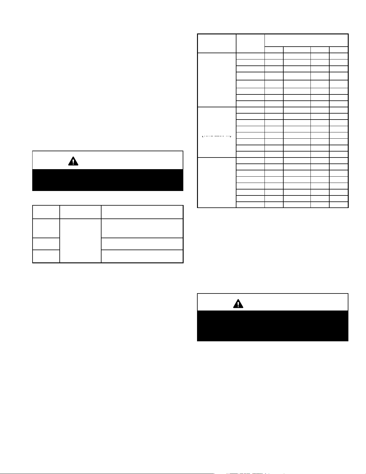
Use the following steps to correctly size vent pipe diameter.
ALTITUDE
MODEL
0 − 4500
4501−7500
(1372 2286 m)
)
1 − Determine the vent termination and its corresponding
equivalent feet value according to table 32.
2 − Determine the number of 90° elbows required for both
indoor and outdoor (e.g. snow riser) use. Calculate the
corresponding equivalent feet of vent pipe.
3 − Determine the number of 45° elbows required for both
indoor and outdoor use. Calculate the corresponding
equivalent feet of vent pipe.
4 − Determine the length of straight pipe required.
5 − Add the total equivalent feet calculated in steps 1
through 4 and compare that length to the maximum
values given in table 34 for the proposed vent pipe diameter. If the total equivalent length required exceeds
the maximum equivalent length listed in the appropriate table, evaluate the next larger size pipe.
IMPORTANT
Do not use screens or perforated metal in exhaust
terminations. Doing so will cause freeze−ups and
may block the terminations.
MINIMUM VENT PIPE LENGTHS
G61MPV
MODEL
045, 070,
071, 090,
091
110, 111**
135***
*Any approved termination may be added to the minimum equivalent length
listed.
**G61MPV−60C−110 must have 90° street ell (supplied) installed directly into
unit flue collar.
***G61MPV−60D−135 must have 3" to 2" reducing ell (supplied) installed directly into unit flue collar.
MIN. EQUIV.
VENT LENGTH
15 ft.*
TABLE 33
EXAMPLE
5 ft. plus 2 elbows of 2", 2−1/2", 3"
or 4" diameter pipe
5 ft. plus 2 elbows of 2−1/2" 3" or 4"
diameter pipe
5 ft. plus 2 elbows of 3" or 4"
diameter pipe
MAXIMUM VENT PIPE LENGTHS
ALTITUDE
0 − 4500
(0 − 1371 m)
4501−7500
(1372−2286 m)
7501 − 10000
(2287 − 3048
m
n/a −− Not allowed.
*G61MPV−60C−110 must have 90° street ell (supplied) installed directly into
unit flue collar.
**G61MPV−60D−135 must have 3" to 2" reducing ell (supplied) installed directly
into unit flue collar.
†On G61MPV−071, −091 and −111 units, sweep elbows must be used for all
90° elbows in the venting system when 2", 2−1/2" or 3" vent pipe is used.
Sweep elbows are recommended for use in vent systems of other
G61MPV units.
‡ On G61MPV−60D−135 units, sweep elbows must be used for all 90°
elbows in the vent system when 3" pipe is used.
G61MPV
045 59 65 77 234
070 59 65 78 214
†
071
090
†
091
110* n/a 32 72 179
†
111
135**
045 59 65 77 234
070 59 65 78 214
0701
090 26 42 72 204
†
091
110* n/a 32 72 179
†
111
135**
045 59 65 77 234
070 59 65 78 214
†
071
090 26 42 72 204
†
091
110* n/a 32 72 179
†
111
135**
MAXIMUM EQUIVALENT VENT
2" dia. 2−1/2" dia. 3" dia. 4" dia.
59 65 78 214
26 42 72 204
26 42 72 204
n/a 32 72 179
‡
n/a n/a 61 160
†
59 65 78 214
26 42 72 204
n/a 32 72 179
‡
n/a n/a 46 160
59 65 78 214
26 42 72 204
n/a 32 72 179
‡
n/a n/a 46 160
LENGTH FEET
B−PVC Joint Cementing Procedure
TABLE 34
All cementing of joints should be done according to the
specifications outlined in ASTM D 2855.
WARNING
DANGER OF EXPLOSION!
Fumes from PVC glue may ignite during system
check. Allow fumes to dissipate for at least 5 minutes
before placing unit into operation.
1 − Measure and cut vent pipe to desired length.
2 − Debur and chamfer end of pipe, removing any ridges
or rough edges. If end is not chamfered, edge of pipe
may remove cement from fitting socket and result in a
leaking joint.
3 − Clean and dry surfaces to be joined.
4 − Test fit joint and mark depth of fitting on outside of pipe.
5 − Uniformly apply liberal coat of PVC primer for PVC or
ABS cleaner for ABS to inside socket surface of fitting
and male end of pipe to depth of fitting socket.
Page 49
Page 50

6 − Promptly apply solvent cement to end of pipe and in-
side socket surface of fitting. Cement should be applied lightly but uniformly to inside of socket. Take
care to keep excess cement out of socket. Apply second coat to end of pipe.
NOTE − Time is critical at this stage. Do not allow primer to dry before applying cement.
7 − Immediately after applying last coat of cement to pipe,
and while both inside socket surface and end of pipe
are wet with cement, forcefully insert end of pipe into
socket until it bottoms out. Turn pipe 1/4 turn during assembly (but not after pipe is fully inserted) to distribute
cement evenly.
NOTE − Assembly should be completed within 20 seconds after last application of cement. Hammer blows
should not be used when inserting pipe.
8 − After assembly, wipe excess cement from pipe at end
of fitting socket. A properly made joint will show a
bead around its entire perimeter. Any gaps may indicate a defective assembly due to insufficient solvent.
9 − Handle joints carefully until completely set.
5. When furnace is installed in a residence where unit is
shut down for an extended period of time, such as a
vacation home, make provisions for draining condensate collection trap and lines.
Exhaust Piping (Figures 22 and 23)
NOTE − A 2" diameter street ell is strapped to the blower
deck of 60C−110 units. Street ell must be
into the unit flue collar. See figure 22. A 3" to 2" reducing
ell is strapped to the blower deck of the 60D−135 units. In
upflow or downflow applications, the reducing ell
must be
1. Choose the appropriate side for venting in upflow or
glued directly into the unit flue collar.
downflow positions. Exhaust piping exits from the top
of the unit in horizontal air discharge applications.
Glue the field−provided exhaust vent pipe (or provided
street ell or reducing ell in upflow or downflow applications) to the flue collar. All cement joints should be
made according to the specifications outlined in ASTM
D 2855. Refer to pipe and fittings specifications and
gluing procedures.
glued directly
C− Venting Practices
The thickness of construction through which vent pipes
may be installed is 24" (610mm) maximum and 3/4"
(19mm) minimum. If a G61MPV furnace replaces a furnace
which was commonly vented with another gas appliance,
the size of the existing vent pipe for that gas appliance must
be checked. Without the heat of the original furnace flue
products, the existing vent pipe is probably oversized for
the single water heater or other appliance. The vent should
be checked for proper draw with the remaining appliance.
1. Use recommended piping materials for exhaust piping.
2. Secure all joints so that they are gas-tight using approved cement.
Suspend piping using hangers at a minimum of every 5
feet (1.52m) for schedule
40 PVC and every 3 feet
(.91m) for ABS−DWV, PVC−
DWV, SPR−21 PVC, and
SDR−26 PVC piping. A suitable hanger can be fabricated by using metal or
plastic strapping or a large
wire tie.
3. In areas where piping penetrates joists or interior
walls, hole must be large enough to allow clearance on
all sides of pipe through center of hole using a hanger.
4. Isolate piping at the point where it exits the outside wall
or roof in order to prevent transmission of vibration to
the structure.
STRAPPING
(metal, plastic
or large wire
ties)
FIGURE 21
IMPORTANT
Exhaust piping and condensate trap must be
installed on the same side of the unit in upflow and
dowflow applications.
2. All horizontal runs of exhaust pipe must slope back toward unit. A minimum of 1/4" (6mm) drop for each 12"
(305mm) of horizontal run is mandatory for drainage.
Horizontal runs of exhaust piping must be supported every 5 feet (1.52m) using hangers.
NOTE − Exhaust piping should be checked carefully to
make sure there are no sags or low spots.
3. On the opposite side of the cabinet, glue the provided
2" vent plug into the unused flue collar.
4. Route piping to outside of structure. Continue with
installation following instructions given in piping termination section.
CAUTION
Do not discharge exhaust into an existing stack or
stack that also serves another gas appliance. If vertical discharge through an existing unused stack is required, insert PVC pipe inside the stack until the end
is even with the top or outlet end of the metal stack.
CAUTION
The exhaust vent pipe operates under positive pressure and must be completely sealed to prevent leakage of combustion products into the living space.
Page 50
Page 51

PLUG
VENT PLUG
(Must be
glued in
place)
PLUG
TYPICAL EXHAUST PIPE CONNECTIONS AND CONDENSATE TRAP INSTALLATION
IN UPFLOW OR DOWNFLOW DIRECT OR NON−DIRECT VENT APPLICATIONS
(Right−Hand Exit in Upflow Application Shown)
2−1/2",
3", OR
4"
2”
TRANSITION
(use only if 4"
pipe is required)
G61MPV−045, 070, 071
090 or 091 with 2−1/2",
2”
3", or 4" vent pipe
2”
PLUG
2"
CONDENSATE
TRAP
(Must be installed
on same side as
exhaust piping)
2”
2”
2−1/2",
3", OR
4"
TRANSITION
2"***
2"*
TRANSITION
4"
3"
3"**
*2" diameter street elbow provided.
**3" diameter reducing elbow provided.
***Limit pipe length to 2".
FIGURE 22
TYPICAL EXHAUST PIPE CONNECTIONS
HORIZONTAL DIRECT OR
NON−DIRECT VENT APPLICATIONS
(Horizontal Right−Hand Air Discharge Application Shown)
*Limit pipe length to 2"
in G61MPV−110 and
−135 applications.
DO NOT transition from
smaller to larger pipe
size in horizontal runs.
2−1/2",
3", OR
4"
TRANSITION
2"*
2"
2"
G61MPV−36B−045
G61MPV−36B−070
G61MPV−36B−071
G61MPV−36C−090
G61MPV−60C−090
G61MPV−60C−091
G61MPV−60C−110*
G61MPV−60C−111*
G61MPV−60D−135*
2"
G61MPV−36B−045
G61MPV−36B−070
G61MPV−36B−071
G61MPV−36C−090
G61MPV−60C−090
G61MPV−60C−091
FIGURE 23
G61MPV−110 with
2−1/2", 3", OR 4"
vent pipe
G61MPV−135 with
3" OR 4" vent pipe
Intake Piping
The G61MPV furnace may be installed in either direct vent
or non−direct vent applications. In non−direct vent applica-
tions, when intake air will be drawn into the furnace from the
surrounding space, the indoor air quality must be considered and guidelines listed in Combustion, Dilution and Ventilation Air section must be followed.
The G61MPV unit is designed for either left−side or right−
side air intake connections in either upflow or downflow applications. In horizontal applications, air intake must be
brought in through the top. Intake air piping is independent
of exhaust piping.
Follow the next four steps when installing the unit in direct
vent applications, where combustion air is taken from outdoors and flue gases are discharged outdoors. The pro-
vided air intake screen must not be used in direct vent applications.
1 − Cement intake piping in slip connector located on the
side of the burner box.
2 − Use a sheet metal screw to secure the intake pipe to the
connector, if desired. A pilot indentation is provided in the
slip connector to assist in locating and starting the fastener.
3 − Glue the provided 2" plug into the unused air intake con-
nector on the opposite side of the cabinet.
4 − Route piping to outside of structure. Continue with instal-
lation following instructions given in general guide lines for
piping terminations and in intake and exhaust piping terminations for direct vent sections. Refer to figure 24 for
pipe sizes.
Page 51
Page 52

TYPICAL AIR INTAKE PIPE CONNECTIONS
UPFLOW OR DOWNFLOW DIRECT VENT APPLICATIONS
(Right−Hand Exit in Upflow Application Shown)
2
PLUG
(Must be
glued in
place)
2
2
G61MPV−36B−045
G61MPV−36B−070
G61MPV−36B−071
G61MPV−36C−090
G61MPV−60C−090
G61MPV−60C−091
FIGURE 24
TYPICAL AIR INTAKE PIPE CONNECTIONS
HORIZONTAL DIRECT VENT APPLICATIONS
(Horizontal Right−Hand Air Discharge Application Shown)
G61MPV−36B−045
G61MPV−36B−070
G61MPV−36B−071
*Limit pipe
length to 2" in
G61MP−110,
−111 and −135
applications.
G61MPV−36C−090
G61MPV−60C−090
G61MPV−60C−091
G61MPV−60C−110*
G61MPV−60C−111*
G61MPV−60D−135*
G61MPV−36B−045
G61MPV−36B−070
G61MPV−36B−071
G61MPV−36C−090
G61MPV−60C−090
G61MPV−60C−091
G61MPV−60C−110*
G61MPV−60C−111*
G61MPV−36B−045
G61MPV−36B−070
G61MPV−36B−071
G61MPV−36C−090
G61MPV−60C−090
G61MPV−60C−091
2”
2”*
2”
2”
2−1/2”,
3” OR 4”
TRANSITION
2”*
2”*
TRANSITION
2−1/2”,
3” OR 4”
2”
2−1/2",
3" OR
4
TRANSITION
2*
2*
G61MPV−36B−045
G61MPV−36B−070
G61MPV−36B−071
G61MPV−36C−090
G61MPV−60C−090
G61MPV−60C−091
G61MPV−60C−110*
G61MPV−60C−111*
TRANSITION
2
2"*
2−1/2",
3" OR
4
G61MPV−36B−045
G61MPV−36B−070
G61MPV−36B−071
G61MPV−36C−090
G61MPV−60C−090
G61MPV−60C−091
G61MPV−60C−110*
G61MPV−60C−111*
G61MPV−60D−135*
*Limit pipe length to 2"
in G61MPV−110, −111
and −135 applications.
Follow the next three steps when installing the unit in NonDirect Vent applications where combustion air is taken
from indoors and flue gases are discharged outdoors.
TYPICAL AIR INTAKE PIPE CONNECTIONS
UPFLOW OR HORIZONTAL NON−DIRECT
(Right−Hand Exit in Upflow Application Shown)
PLUG
(Must be
glued in
place)
VENT APPLICATIONS
6 in. Max.
INTAKE
DEBRIS
SCREEN
(Provided)
FIGURE 25
NOTE − Debris screen and elbow may be rotated, so that
screen may be positioned to face forward, backward or
downward.
FIGURE 26
Page 52
Page 53

TYPICAL AIR INTAKE PIPE CONNECTIONS
DOWNFLOW NON−DIRECT VENT APPLICATIONS
(Right−Hand Exit in Downflow Applications Shown)
2" SWEEP
ELL
INTAKE
DEBRIS
SCREEN
(Provided)
PLUG
(Must be
glued in
place)
6 in. Max.
INTAKE DEBRIS
SCREEN
(Provided)
Downflow
Evaporator
Coil
FIGURE 27
1 − Use field−provided materials and the factory−provided
air intake screen to route the intake piping as shown in
figures 26 and 27. Maintain a minimum clearance of 3"
(76mm) around the air intake opening. The air intake
opening (with the protective screen) should always be
directed either downward or straight out. Use 2" pipe
and fittings only and make sure that the air intake does
not extend more than 6" beyond the G61MPV cabinet.
The air intake connector must not be located near
the floor. To avoid this complication in downflow
applications which do not include a downflow
evaporator coil, the intake air routing should be modi-
fied as shown in figure 27.
2 − Use a sheet metal screw to secure the intake pipe to the
connector, if desired. A pilot indentation is provided in the
slip connector to assist in locating and starting the fastener.
3 − Glue the provided 2" plug into the unused air intake con-
nector on the opposite side of the cabinet.
PLUG
(Must be
glued in
place)
Downflow Additive Flloor Base
NOTE − Debris screen and sweep ell may be rotated, so that
screen may be positioned to face forward, backward or to the side.
2"
2" SWEEP ELL
18 in.
Testing for Proper Venting and Sufficient Combustion Air
(Non−Direct Vent Applications Only)
WARNING
CARBON MONOXIDE POISONING HAZARD!
Failure to follow the steps outlined below for each
appliance connected to the venting system being
placed into operation could result in carbon monoxide poisoning or death.
The following steps shall be followed for each appliance connected to the venting system being
placed into operation, while all other appliances connected to the venting system are not in operation.
After the G61MPV gas furnace has been started, the following test should be conducted to ensure proper venting
and sufficient combustion air has been provided to the
G61MPV, as well as to other gas-fired appliances which
are separately vented. The test should be conducted while
all appliances (both in operation and those not in operation)
are connected to the venting system being tested. If the
venting system has been installed improperly, or if provisions have not been made for sufficient amounts of combustion air, corrections must be made as outlined in the
previous section.
1 − Seal any unused openings in the venting system.
2 − Visually inspect the venting system for proper size and
horizontal pitch. Determine there is no blockage or restriction, leakage, corrosion, or other deficiencies
which could cause an unsafe condition.
Page 53
Page 54

3 − To the extent that it is practical, close all building doors
and windows and all doors between the space in which
the appliances connected to the venting system are lo-
cated and other spaces of the building.
4 − Close fireplace dampers.
5 − Turn on clothes dryers and any appliances not con-
nected to the venting system. Turn on any exhaust
fans, such as range hoods and bathroom exhausts, so
they will operate at maximum speed. Do not operate a
summer exhaust fan.
6 − Follow the lighting instruction to place the appliance
being inspected into operation. Adjust thermostat so
appliance will operate continuously.
7 − Use the flame of a match or candle to test for spillage
of flue gases at the draft hood relief opening after 5
minutes of main burner operation.
8 − If improper venting is observed during any of the
above tests, the venting system must be corrected or
sufficient combustion/make-up air must be provided.
The venting system should be re-sized to approach
the minimum size as determined by using the ap-
propriate tables in appendix G in the current standards
of the National Fuel Gas Code ANSI−Z223.1/NPFA 54
in the U.S.A., and the appropriate Natural Gas and
Propane appliances venting sizing tables in the cur-
rent standard of the CSA−B149 Natural Gas and Pro-
pane Installation Codes in Canada.
9 − After determining that each appliance remaining
connected to the common venting system properly
vents when tested as indicated in step 3, return
doors, windows, exhaust fans, fireplace dampers
and any other gas-burning appliance to their previous
condition of use.
General Guidelines for Vent Terminations for Non-Direct
Vent Installations.
In Non-Direct Vent applications, combustion air is taken
from indoors and the flue gases are discharged to the outdoors. The G61MPV is then classified as a non-direct
vent, Category IV gas furnace. In Non-Direct Vent applications, the vent termination is limited by local building
codes. In the absence of local codes, refer to the current
National Fuel Gas Code ANSI Z223−1/NFPA 54 in U.S.A.,
and current CSA−B149 Natural Gas and Propane Installation Codes in Canada for details.
Position termination end according to location given in figure 28. In addition, position termination end so it is free
from any obstructions and above the level of snow accu-
mulation (where applicable). The termination should be at
least 12 inches (305mm) from any opening through which
flue products could enter the building.
At vent termination, care must be taken to maintain
protective coatings over building materials (prolonged
exposure to exhaust condensate can destroy protective
coatings). It is recommended that the exhaust outlet not be
located within 6 feet (1.8m) of a condensing unit because
the condensate can damage the painted coating.
NOTE − If winter design temperature is below 32°F (0°C),
exhaust piping should be insulated with 1/2" (13mm), Armaflex or equivalent when run through unheated space.
Do not leave any surface area of exhaust pipe open to outside air; exterior exhaust pipe should be insulated with 1/2"
(13mm) Armaflex or equivalent. In extreme cold climate
areas, 3/4" (19mm) Armaflex or equivalent may be necessary. Insulation on outside runs of exhaust pipe must be
painted or wrapped to protect insulation from deterioration.
Exhaust pipe insulation may not be necessary in some
specific applications.
NOTE − During extremely cold temperatures, below
approximately 20°F (6.7°C), units with long runs of vent
pipe through unconditioned space, even when insulated,
may form ice in the exhaust termination that prevents the
unit from operating properly. Longer run times of at least 5
minutes will alleviate most icing problems. Also, a heating
cable may be installed on exhaust piping and termination to
prevent freeze−ups. Heating cable installation kit is available from Lennox. See Condensate Piping section for part
numbers.
IMPORTANT
Do not use screens or perforated metal in exhaust
terminations. Doing so will cause freeze−ups and
may block the terminations.
IMPORTANT
For Canadian Installations Only:
In accordance to CSA International B149 installation
codes, the minimum allowed distance between the
combustion air intake inlet and the exhaust outlet of
other appliances shall not be less than 12 inches
(305mm).
Page 54
Page 55

VENT TERMINATION CLEARANCES
FOR INSTALLATIONS IN THE USA AND CANADA*
− G61MPV VENT TERMINATION
− AIR INLET OF OTHER APPLIANCE
C
less than
10 ft (3.048M)
D
D
E
F
G
A − Clearance above grade − 12 in. (305mm) minimum.
B − Clearance to window or door that may be opened −
for vent installations in USA − 12 in. (305mm) minimum.
for vent installations in Canada − 12 in. (305mm) minimum
for appliances 100,000 Btuh (30 kW);
36 in. (0.9m) minimum for appliances > 100,000 Btuh (30
kW).
C − Do not position terminations directly under roof eaves.
D − Clearance to electric meters, gas meters, regulators, and
relief equipment −
for vent installations in USA − 48 in (1219mm) minimum.
for vent installations in Canada − see current edition of CSA
B149 Code.
* Note −
(I) Dimensions are from the current edition of The National Fuel Gas Code − ANSI-Z223.1/NFPA 54 for USA installations. In Canada, refer to current edition of CSA B149 installation codes. Local codes or regulations may require different clearances.
(II) In Non-Direct Vent installations, combustion air is taken from indoors and the flue gases are discharged to the outdoors.
E − Clearance to non−mechanical air supply inlet or outlet
for vent installations in USA − 48 in. (1219mm) minimum
horizontal and below, 12 in. (305mm) minimum above.
for vent installations in Canada − 12 in. (305mm) minimum
for appliances 100,000 Btuh (30 kW);
36 in. (0.9m) minimum for appliances > 100,000 Btuh (30
kW).
F − Clearance to mechanical air supply inlet −−
for vent installations in USA − 36 in. minimum (914mm).
G − Clearance to mechanical air supply inlet −−
for vent installations in Canada − 72 in. (1829mm) minimum.
H − Do not point terminations into recessed areas such as win-
dow wells, stairwells or alcoves.
J − Do not position terminations directly above a walkway.
FIGURE 28
Page 55
Page 56

Details of Intake and Exhaust Piping Terminations for
Direct Vent Installations
NOTE − In Direct Vent installations, combustion air is taken
from outdoors and flue gases are discharged to outdoors.
Intake and exhaust pipes may be routed either horizontally
through an outside wall or vertically through the roof. In attic or closet installations, vertical termination through the
roof is preferred. Figures 29 through 37 show typical terminations.
1. Exhaust and intake exits must be in same pressure
zone. Do not exit one through the roof and one on the
side. Also, do not exit the intake on one side and the
exhaust on another side of the house or structure.
2. Intake and exhaust pipes should be placed as close
together as possible at termination end (refer to illustrations). Maximum separation is 3" (76mm) on roof
terminations and 6" (152mm) on side wall terminations.
3. If necessary, install a field−provided reducer to adapt
larger vent pipe size to termination pipe size.
4. On roof terminations, the intake piping should terminate straight down using two 90° elbows (See figure
29).
5. Exhaust piping must terminate straight out or up as
shown. In rooftop applications, a reducer may be required on the exhaust piping at the point where it exits
the structure to improve the velocity of exhaust away
from the intake piping. See table 35.
NOTE − Care must be taken to avoid recirculation of
exhaust back into intake pipe.
6. On field supplied terminations for side wall exits, exhaust piping should extend a maximum of 12 inches
(305mm) beyond the outside wall unless supported.
Intake piping should be as short as possible. See figure 30.
7. On field supplied terminations, a minimum separation
distance between the end of the exhaust pipe and the
end of the intake pipe is 8 inches (203mm).
8. If intake and exhaust piping must be run up a side wall
to position above snow accumulation or other obstructions, piping must be supported every 3 ft. (.9m) as
shown in figure 21. Refer to figure 33 for proper piping
method. In addition, WTK wall termination kit must be
extended for use in this application. See figure 36.
When exhaust and intake piping must be run up an
outside wall, the exhaust piping must be terminated
with pipe sized per table 35. The intake piping may be
equipped with a 90° elbow turndown. Using turndown
will add 5 feet (1.5m) to the equivalent length of the
pipe.
9. Based on the recommendation of the manufacturer, a
multiple furnace installation may use a group of up to
four termination kits WTK assembled together horizontally, as shown in figure 35.
TABLE 35
EXHAUST PIPE TERMINATION SIZE REDUCTION
G61MPV
MODEL
045, 070, −071 2", 2−1/2", 3" or 4" 1−1/2"
090, 091 2", 2−1/2", 3" or 4" 2"
110, 111 2−1/2", 3" or 4" 2"*
135 3" or 4" 2"*
*Approved 3" concentric termination kit terminates with 2−5/8" ID pipe.
Inches(mm)
8" (203) MIN
12" (305) ABOVE
AVERAGE SNOW
ACCUMULATION
3" (76) OR
2" (51) PVC
PROVIDE SUPPORT
FOR INTAKE AND
EXHAUST LINES
Exhaust Pipe Size Termination Pipe Size
3(76) MAX.
DIRECT VENT ROOF TERMINATION KIT
(15F75 or 44J41)
SIZE TERMINATION
PIPE PER TABLE 35.
UNCONDITIONED
ATTIC SPACE
1/2" (13) FOAM
INSULATION IN
UNCONDITIONED
SPACE
FIGURE 29
12" (305) MAX.
1/2" (13) ARMAFLEX
INSULATION IN
UNCONDITIONED SPACE
FIELD−
PROVIDED
REDUCER MAY
BE REQUIRED
TO ADAPT
LARGER VENT
PIPE SIZE TO
TERMINATION
OUTSIDE
WALL
2" (51) PVC
COUPLING
TOP VIEW WALL RING KIT
(unless supported)
6" (152)
MAXIMUM
MINIMUM
(15F74)
8" (203)
1/2" (13)
ARMAFLEX
INSULATION
SIZE
TERMINATION
PIPE PER
TABLE 35.
Inches (mm)
FIGURE 30
Page 56
Page 57

EXHAUST
TERMINATION
INTAKE
TERMINATION
12" (305) ABOVE
AVERAGE SNOW
ACCUMULATION
Inches (mm)
INTAKE
VENT
EXHAUST VENT
Front View
FIELD−PROVIDED
REDUCER MAY BE REQUIRED
TO ADAPT LARGER VENT
PIPE SIZE TO TERMINATION
EXHAUST
INTAKE
DIRECT VENT CONCENTRIC ROOFTOP TERMINATION
(71M80, 69M29 or 60L46)
FIGURE 31
Inches (mm)
EXHAUST
INTAKE
FIELD−PROVIDED
REDUCER MAY
BE REQUIRED TO
ADAPT LARGER
VENT PIPE SIZE
TO TERMINATION
DIRECT VENT CONCENTRIC WALL TERMINATION
(71M80, 69M29 or 60L46)
INTAKE
TERMINATION
EXHAUST
TERMINATION
12" (305) Min.
above grade.
FIGURE 32
1/2" (13) Foam Insulation
in Unconditioned Space
FIELD−
PROVIDED
REDUCER MAY
BE REQUIRED
TO ADAPT
LARGER VENT
PIPE SIZE TO
TERMINATION
Inches (mm)
DIRECT VENT WALL TERMINATION KIT
(22G44, 44J40, 30G28 or 81J20)
EXHAUST
VENT
INTAKE
VENT
Inches (mm)
FIGURE 34
5"
(127)
18" MAX.
(457)
Side View
EXHAUST VENT
INTAKE VENT
OUTSIDE WALL
12"
(305)
5−1/2"
(140)
Front View
EXHAUST VENT
INTAKE
VENT
Side View
12" (305) MAX. for 2" (51)
Inches(mm)
UNCONDITIONED
SPACE
OUTSIDE WALL
PROVIDE SUPPORT
FOR INTAKE AND
EXHAUST LINES EVERY
36" (914)
FIELD−PROVIDED
REDUCER MAY
BE REQUIRED TO
ADAPT LARGER
VENT PIPE SIZE
TO TERMINATION
1/2" (13) FOAM
INSULATION IN
UNCONDITIONED
SPACE
(unless supported)
8 (203)
MIN.
12" (305) ABOVE
AVERAGE SNOW
ACCUMULATION
1/2" (13) FOAM
INSULATION
SIZE
TERMINATION
PIPE PER
TABLE 35.
SIDE VIEW
DIRECT VENT WALL RING TERMINATION
(15F74)
See venting table 34 for maximum venting lengths with this arrange-
ment.
FIGURE 33
OPTIONAL VENT TERMINATION FOR MULTIPLE UNIT
INSTALLATION OF DIRECT VENT WALL TERMINATION KIT WTK
FIGURE 35
Page 57
Page 58

INTAKE
AIR
GRADE
12" (305) MAX. for 2" (51)
20" (508) MAX. for 3" (76)
(unless supported)
8" (203)
Minimum
Side View
Inches (mm)
EXHAUST
AIR
12" (305)
Minimum
ABOVE GRADE
INTAKE
AIR
5"
(127)
12"
(305)
5-1/2"
(140)
COVER EXHAUST
VENT WITH
1/2" (13)
FOAM
INSULATION
EXHAUST
AIR
12" MIN.
(305)
Above Grade
GRADE
DIRECT VENT TERMINATION
WALL TERMINATION KIT (22G44, 44J40, 30G28 or 81J20) EXTENDED VENT FOR GRADE CLEARANCE
FIGURE 36
Front View
G61MPV DIRECT VENT APPLICATION
USING EXISTING CHIMNEY
3" − 8"
8" − 12"
(203mm − 305mm)
INTAKE PIPE
INSULATION (optional)
SHEET
METAL TOP
PLATE
MINIMUM 12"
(305mm) ABOVE
ROOF
INSULATE
TO FORM
SEAL
*SIZE TERMINATION
PIPE PER TABLE 35.
NOTE − Do not discharge exhaust gases directly into any chimney or vent stack. If vertical discharge through an existing unused chimney or stack is required, insert piping
inside chimney until the pipe open end is above top of chimney and terminate as illustrated. In any exterior portion of chimney, the exhaust vent must be insulated.
(76mm−
203mm)
STRAIGHT−CUT OR
ANGLE−CUT IN DIRECTION
OF ROOF SLOPE *
EXHAUST VENT
1/2" (13mm)
WEATHERPROOF
INSULATION
SHOULDER OF FITTINGS
PROVIDE SUPPORT
OF PIPE ON TOP PLATE
3" − 8"
(76mm−
203mm)
ALTERNATE
INTAKE PIPE
EXTERIOR
PORTION OF
CHIMNEY
FIGURE 37
Details of Exhaust Piping Terminations for Non-Direct
Vent Applications
Exhaust pipes may be routed either horizontally through an
outside wall or vertically through the roof. In attic or closet
installations, vertical termination through the roof is preferred. Figures 38 through 41 show typical terminations.
1. Exhaust piping must terminate straight out or up as
shown. The termination pipe must be sized as listed in
table 35.The specified pipe size ensures proper velocity required to move the exhaust gases away from
the building.
2. On field supplied terminations for side wall exits, exhaust piping should extend a maximum of 12 inches
(305mm) beyond the outside wall, unless support is
provided in the horizontal section. See figure 39.
Inches(mm)
12" (305mm)
ABOVE AVE.
SNOW
ACCUMULATION
3" (76) OR
2" (51) PVC
PROVIDE SUPPORT
FOR EXHAUST LINES
SIZE TERMINATION
PIPE PER TABLE
35.
UNCONDITIONED
ATTIC SPACE
NON−DIRECT VENT ROOF TERMINATION KIT
(15F75 or 44J41)
FIGURE 38
12" (305) Max. for 2" (51)
1/2" (13) ARMAFLEX
INSULATION IN
UNCONDITIONED SPACE
FIELD−PROVIDED
REDUCER MAY
BE REQUIRED TO
ADAPT LARGER
VENT PIPE SIZE
TO TERMINATION
Inches (mm)
Unless Supported
PVC REDUCER
SIZE TERMINATION
PIPE PER TABLE 35.
1/2" (13)
ARMAFLEX
INSULATION
TOP VIEW
NON−DIRECT VENT WALL RING KIT
(15F74)
FIGURE 39
3. If exhaust piping must be run up a side wall to position
above snow accumulation or other obstructions, piping must be supported every 3 feet (.9m) as shown in
figure 21. Refer to figure 40 for proper piping method.
When exhaust piping must be run up an outside wall,
any reduction in exhaust pipe size must be done after
the final elbow.
Page 58
Page 59

Inches(mm)
UNCONDITIONED
SPACE
OUTSIDE WALL
PROVIDE SUPPORT
FOR EXHAUST LINES
EVERY 36" (914)
FIELD−PROVIDED
REDUCER MAY BE
REQUIRED TO
ADAPT LARGER
VENT PIPE SIZE TO
TERMINATION
1/2" (13) FOAM
INSULATION IN
UNCONDITIONED
SPACE
12" (305) Max. for 2" (51)
Unless Supported
SIZE TERMINATION
PIPE PER
TABLE 35.
12" (305) ABOVE
AVERAGE SNOW
ACCUMULATION
1/2" (13) FOAM
INSULATION
SIDE VIEW
NON−DIRECT VENT WALL RING TERMINATION
(15F74)
FIGURE 40
G61MPV NON−DIRECT VENT APPLICATION
USING EXISTING CHIMNEY
SIZE TERMINATION
PIPE PER TABLE 35.
3" − 8"
(76mm−
MINIMUM 12"
MINIMUM
12" (304mm)
(305mm) ABOVE
ABOVE AVERAGE
AVERAGE SNOW
SNOW ACCUMULATION
ACCUMULATION
METAL TOP
INSULATE
TO FORM
SEAL
NOTE − Do not discharge exhaust gases directly into any chimney or vent stack. If vertical discharge through an existing unused chimney or stack is required, insert piping
inside chimney until the pipe open end is above top of chimney and terminate as illustrated. In any exterior portion of chimney, the exhaust vent must be insulated.
203mm)
SHEET
PLATE
STRAIGHT−CUT OR
ANGLE−CUT IN DIRECTION
OF ROOF SLOPE
EXHAUST VENT
1/2" (13mm)
WEATHERPROOF
INSULATION
SHOULDER OF FITTINGS
PROVIDE SUPPORT
OF PIPE ON TOP PLATE
3" − 8"
(76mm−
203mm)
EXTERIOR
PORTION OF
CHIMNEY
FIGURE 41
Condensate Piping
This unit is designed for either right- or left-side exit of condensate piping in either upflow or downflow applications;
however, it must be installed on the same side of the unit as
the exhaust piping. In horizontal applications, the condensate trap should extend below the unit. A 5−1/2" service
clearance is required for the condensate trap. Refer to figure 42 for condensate trap locations.
CONDENSATE TRAP LOCATIONS
(Unit shown in upflow position)
Horizontal
left and
optional
downflow
Optional
upflow
Horizontal
right and
optional
downflow
Optional
upflow
NOTE − In upflow applications where side return
air filter is installed on same side as the condensate trap, filter rack must be installed beyond
condensate trap to avoid interference.
FIGURE 42
1 − Determine which side condensate piping will exit the
unit. Remove plugs from the condensate collar at the
appropriate location on the side of the unit.
NOTE − The condensate trap is factory−shipped with
two rubber O−rings and two rubber clean−out caps
installed. Check to make sure that these items are in
place before installing the trap assembly.
2 − Install condensate trap onto the condensate collar.
Use provided HI/LO screws to secure two upper
flanges of the trap to the collar. Use provided sheet
metal screw to secure bottom trap flange to side of
unit. See figure 43.
NOTE − In upflow and downflow applications, condensate trap must be installed on the same side as
exhaust piping.
CAUTION
DO NOT use a power driver to tighten screws which
secure condensate trap to cabinet. Screws should
be hand−tightened using a screw driver to avoid the
possibility of damage to the trap assembly.
Page 59
Page 60

3 − Glue the field−provided coupling or pipe to the trap.
Install a tee and vent pipe near the trap.
NOTE − The condensate trap drain stubs (both sides)
have an outer diameter which will accept a standard
3/4" PVC coupling. The inner diameter of each stub
will accept standard 1/2" diameter PVC pipe.
NOTE − Vinyl tubing may be used for condensate
drain. Tubing must be 1−1/4" OD X 1" ID and should be
attached to the drain stubs on the trap using a hose
clamp.
4 − Glue the field−provided drain line to the tee. Route the
drain line to an open drain. As an alternate, clear vinyl
tubing may be used to drain condensate away from
the trap. Secure the vinyl tubing to the drain stubs on
the trap using a hose clamp. Do not overtighten the
hose clamp.
Condensate line must be sloped downward away from
condensate trap to drain. If drain level is above condensate trap, condensate pump must be used. Condensate drain line should be routed within the conditioned space to avoid freezing of condensate and
blockage of drain line. If this is not possible, a heat
cable kit may be used on the condensate trap and line.
Heating cable kit is available from Lennox in various
lengths; 6 ft. (1.8m) − kit no. 26K68; 24 ft. (7.3m) − kit
no. 26K69; and 50 ft. (15.2m) − kit no. 26K70.
CAUTION
Do not use copper tubing or existing copper
condensate lines for drain line.
5 − If unit will be started immediately upon completion of
installation, prime trap per procedure outlined in Unit
Start−Up section.
6 − Glue the provided cap onto the unused condensate
drain line stub.
CONDENSATE ASSEMBLY
HI/LO SCREWS
CAP
O−RINGS
SCREW
(DO NOT use power
driver. Hand−tighten
using screw driver.)
NIPPLE
COUPLING
CLEAN−OUT ACCESS
CONDENSATE TRAP
VENT
NIPPLE
TEE
(both sides)
FIGURE 43
Page 60
Page 61

III−START-UP
A−Preliminary and Seasonal Checks
1 − Inspect electrical wiring, both field and factory installed
for loose connections. Tighten as required.
2 − Check voltage at disconnect switch. Voltage must be
within range listed on the nameplate. If not, consult the
power company and have voltage condition corrected
before starting unit.
B−Heating Start-Up
FOR YOUR SAFETY READ BEFORE OPERATING
WARNING
Shock and burn hazard.
G61MPV units are equipped with a hot surface ignition system. Do not attempt to light manually.
BEFORE LIGHTING the unit, smell all around the fur-
nace area for gas. Be sure to smell next to the floor because some gas is heavier than air and will settle on the
floor.
The gas valve on the G61MPV may be equipped with either a gas control knob or gas control lever. Use only your
hand to push the lever or turn the gas control knob. Never
use tools. If the the lever will not move or the knob will not
push in or turn by hand, do not try to repair it. Force or attempted repair may result in a fire or explosion.
Placing the furnace into operation:
G61MPV units are equipped with a SureLight
system. Do not
attempt to manually light burners on this
furnace. Each time the thermostat calls for heat, the
burners will automatically light. The ignitor does not get
hot when there is no call for heat on units with SureLight
ignition system.
Priming Condensate Trap
The condensate trap should be primed with water prior to
start−up to ensure proper condensate drainage. Either
pour 10 fl. oz. (300 ml) of water into the trap, or follow
these steps to prime the trap:
1 − Follow the lighting instructions to place the unit into op-
eration.
2 − Set the thermostat to initiate a heating demand.
3 − Allow the burners to fire for approximately 3 minutes.
4 − Adjust the thermostat to deactivate the heating de-
mand.
5 − Wait for the combustion air inducer to stop. Set the
thermostat to initiate a heating demand and again allow the burners to fire for approximately 3 minutes.
6 − Adjust the thermostat to deactivate the heating de-
mand and again wait for the combustion air inducer to
stop. At this point, the trap should be primed with sufficient water to ensure proper condensate drain operation.
®
ignition
WARNING
If you do not follow these instructions exactly, a fire
or explosion may result causing property damage,
personal injury or death.
Gas Valve Operation (Figures 44 and 45)
1 − STOP! Read the safety information at the beginning of
this section.
2 − Set the thermostat to the lowest setting.
3 − Turn off all electrical power to the unit.
4 − This furnace is equipped with an ignition device which
automatically lights the burners. Do not try to light the
burners by hand.
5 − Remove the upper access panel.
6 − Honeywell VR8205 Gas Valve − Turn knob on gas
valve clockwise
44.
White Rodgers 36E Gas Valve − Switch gas valve le-
ver to OFF. See figure 45 for the White Rodgers 36E
valve.
7 − Wait five minutes to clear out any gas. If you then smell
®
gas, STOP! Immediately call your gas supplier from a
neighbor’s phone. Follow the gas supplier’s instruc-
tions. If you do not smell gas go to next step.
HONEYWELL VR8205 Series Gas Valve
HIGH FIRE
ADJUSTMENT
SCREW
(under cap)
LOW FIRE
ADJUSTMENT
SCREW
(under cap)
hose barb in place of cap
GAS VALVE SHOWN IN OFF POSITION
to OFF. Do not force. See figure
REFERENCE TO
BURNER BOX
iNLET PRESSURE TAP
FIGURE 44
MANIFOLD
PRESSURE
TAP
Page 61
Page 62

WHITE RODGERS 36E SERIES GAS VALVE
HIGH FIRE
MANIFOLD
PRESSURE
ADJUSTMENT
ON SIDE
(under cap)
IV−HEATING SYSTEM SERVICE CHECKS
A−C.S.A. Certification
All units are C.S.A. (formally A.G.A. and C.G.A. combined)
design certified without modifications. Refer to the
G61MPV Installation Instruction.
B−Gas Piping
MANIFOLD
PRESSURE
TAP ON SIDE
INLET PRESSURE
TAP ON SIDE
GAS VALVE SHOWN IN OFF POSITION
8 − Honeywell VR8205 Gas Valve − Turn knob on gas
valve counterclockwise
White Rodgers 36E Gas Valve − Switch gas valve lever
to ON. See figure 45 for the White Rodgers 36E
valve.
9 − Replace the upper access panel.
10− Turn on all electrical power to to the unit.
11− Set the thermostat to desired setting.
NOTE − When unit is initially started, steps 1 through 11
may need to be repeated to purge air from gas line.
12− If the appliance will not operate, follow the instructions
Turning Off Gas to Unit" and call your service technician or gas supplier.
Turning Off Gas to Unit
1 − Set the thermostat to the lowest setting.
2 − Turn off all electrical power to the unit if service is to be
performed.
LOW FIRE MANIFOLD
PRESSURE ADJUSTMENT
ON SIDE (under cap)
FIGURE 45
to ON. Do not force.
CAUTION
If a flexible gas connector is required or allowed by
the authority that has jurisdiction, black iron pipe
shall be installed at the gas valve and extend outside
the furnace cabinet.
WARNING
Do not exceed 600 in−lbs (50 ft−lbs) torque when
attaching the gas piping to the gas valve.
Gas supply piping should not allow more than 0.5"W.C. drop
in pressure between gas meter and unit. Supply gas pipe
must not be smaller than unit gas connection.
Compounds used on gas piping threaded joints should be
resistant to action of liquefied petroleum gases.
C−Testing Gas Piping
IMPORTANT
In case emergency shutdown is required, turn off
the main shut-off valve and disconnect the main
power to unit. These controls should be properly
labeled by the installer.
When pressure testing gas lines, the gas valve must be disconnected and isolated. Gas valves can be damaged if
subjected to more than 0.5psig (14" W.C.). See figure 46.
GAS PIPING TEST PROCEDURE
MANUAL MAIN SHUT−OFF VALVE
3 − Remove the upper access panel.
4 − Honeywell VR8205 Gas Valve − Turn knob on gas
valve clockwise
White Rodgers 36E Gas Valve − Switch gas valve lever to OFF.
5 − Replace the upper access panel.
to OFF. Do not force.
C−Safety or Emergency Shutdown
Turn off unit power. Close manual and main gas valves.
D−Extended Period Shutdown
Turn off thermostat or set to UNOCCUPIED" mode. Close
all gas valves (both internal and external to unit) to guarantee no gas leak into combustion chamber. Turn off power to
unit. All access panels and covers must be in place and secured.
CAP
GAS VALVE
FIGURE 46
When checking piping connections for gas leaks, use preferred means. Kitchen detergents can cause harmful corrosion on various metals used in gas piping. Use of a specialty
Gas Leak Detector is strongly recommended. It is available
through Lennox under part number 31B2001. See Corp.
8411−L10, for further details.
Do not use matches, candles, flame or any other source of
ignition to check for gas leaks.
Page 62
Page 63

D−Testing Gas Supply Pressure
G61MPV
When testing supply gas pressure, connect test gauge to
inlet pressure tap on the gas valve. See figures and 44 and
45. Check gas line pressure with unit firing at maximum
rate. Low pressure may result in erratic operation or underfire. High pressure can result in permanent damage to gas
valve or overfire. See table 36 for operating pressure at unit
gas connection (line).
On multiple unit installations, each unit should be checked
separately, with and without units operating. Supply pressure must fall within range listed in table 36.
TABLE 36
All G61MPV Units
Line Pressure WC" 4.5 − 10.5 11.0 − 13.0
Natural LP
E−Check Manifold Pressure
After line pressure has been checked and adjusted, check
manifold pressure. Move pressure gauge to outlet pressure tap located on unit gas valve (GV1). Checks of manifold pressure are made as verification of proper regulator adjustment. Manifold pressure for the G61MPV can be measured at any time the gas valve is open and is supplying gas
to the unit. See table 40 for manifold pressures.
NOTE − Shut unit off and remove manometer as soon as an
accurate reading has been obtained. Take care to replace
pressure tap plug.
NOTE − During this test procedure, the unit will be overfiring:
D Operate unit only long enough to obtain accurate read-
ing to prevent overheating heat exchanger.
D Attempts to clock gas meter during this procedure will
be inaccurate. Measure gas flow rate only during normal unit operation.
7 − When test is complete remove obstruction from hose
and return hose to gas valve barbed fitting.
F− Proper Gas Flow (Approximate)
Furnace should operate at least 5 minutes before checking gas flow. Determine time in seconds for two revolutions of gas through the meter. (Two revolutions assures a
more accurate time.) Divide by two and compare to time
in table 37 below. If manifold pressure matches table 36
and rate is incorrect, check gas orifices for proper size and
restriction.
NOTE− To obtain accurate reading, shut off all other gas
appliances connected to meter.
TABLE 37
IMPORTANT
For safety, connect a shut-off valve between the
manometer and the gas tap to permit shut off of
gas pressure to the manometer.
The gas valve is factory set and should not require adjustment. All gas valves are factory regulated sensing atmo-
spheric pressure.
Manifold Pressure Measurement & Adjustment
NOTE − Pressure test adapter kit (10L34) is available from
Lennox to facilitate manifold pressure measurement.
1 − Connect test gauge to outlet tap on gas valve.
2 − Disconnect pressure sensing hose from gas valve and
plug hose using tape or equivalent. Leave hose barb
on valve open.
3 − Start unit on low heat and allow 5 minutes for unit to
reach steady state.
4 − While waiting for the unit to stabilize, notice the flame.
Flame should be stable and should not lift from burner.
Natural gas should burn blue.
5 − After allowing unit to stabilize for 5 minutes, record
manifold pressure and compare to value given in table
40.
6 − Repeat steps 3, 4 and 5 on high heat.
GAS METER CLOCKING CHART
Seconds for One Revolution
G61MPV
Unit
−45 82 164 205 410
−70, −071 55 110 136 272
−90, −091 41 82 102 204
−110, −111 33 66 82 164
−135 27 54 68 136
Natural−1000 btu/cu ft LP−2500 btu/cu ft
Natural LP
1 cu ft
Dial
2 cu ft
Dial
1 cu ft
Dial
2 cu ft
DIAL
IMPORTANT
For safety, shut unit off and remove manometer as
soon as an accurate reading has been obtained.
Take care to replace pressure tap plug.
G− Proper Combustion
Furnace should operate minimum 15 minutes with correct
manifold pressure and gas flow rate before checking combustion. See sections E− and F−. Take combustion sample
beyond the flue outlet and compare to the following tables.
The maximum carbon monoxide reading should not exceed 100 ppm.
Page 63
Page 64

TABLE 38
High Heat
Unit
CO2%
For Nat
CO2%
For L.P.
G61MPV−36B−045 6.0 − 7.0 6.9 − 7.9
G61MPV−36B−070 6.5 − 7.6 7.4 − 8.4
G61MPV−36B−071 6.9 − 8.2 8.3 − 9.8
G61MPV−36C−090 6.9 − 8.0 7.8 − 8.8
G61MPV−60C−090 6.7 − 7.7 7.8 − 8.8
G61MPV−60C−091 7.6 − 8.9 8.7 − 10.2
G61MPV−60C−110 7.2 − 8.2 8.1 − 9.1
G61MPV−60C−111 7.5 − 8.8 8.7 − 10.2
G61MPV−60D−135 7.4 − 8.5 8.3 − 9.3
TABLE 39
Low Heat
Unit
CO2%
For Nat
CO2%
For L.P.
G61MPV−36B−045 4.3 − 5.3 4.8 − 5.8
G61MPV−36B−070 4.8 − 5.8 5.3 − 6.3
G61MPV−36B−071 5.0 − 6.2 5.7 − 7.0
G61MPV−36C−090 5.1 − 6.5 5.9 − 6.9
G61MPV−60C−090 5.1 − 6.5 5.9 − 6.9
G61MPV−60C−091 5.4 − 6.7 6.2 − 7.4
G61MPV−60C−110 5.3 − 6.5 6.1 − 7.1
G61MPV−60C−111 5.3 − 6.5 6.1 − 7.4
G61MPV−60D−135 6.5 − 7.5 6.7 − 7.7
pH RANGE
0
1
Increasing
Acidity
Increasing
Alkalinity
2
3
4
5
6
7
8
9
10
11
Vinegar
Wine
Orange Juice
Tomato Juice
Tap Water
G61 Condensate
pH Range
I− High Altitude
NOTE − In Canada, certification for installations at elevations over 4500 feet (1372 m) is the jurisdiction of local authorities.
The manifold pressure may require adjustment to ensure
proper operation at higher altitudes. Refer to tables 40, 41
and 42 for proper manifold pressure settings at varying altitudes and required pressure switch changes and conversion kits at varying altitudes.
The combustion air pressure switches are factory−set and
require no adjustment.
NOTE − A natural to L.P. propane gas changeover kit is necessary to convert this unit. Refer to the changeover kit
installation instruction for the conversion procedure.
H− Condensate pH Range
The condensate is mildly acidic and can be measured with
pH indicators. The pH scale is a measurement of acidity
and alkalinity. The following scale shows the relative pH of
some common liquids as compared with condensate of
G61MPV units. The concentration of the acidity of all these
fluids including the condensate is very low and harmless.
Page 64
Page 65

TABLE 40
Conversion Kit Requirements and Manifold Pressures for Models
−045, −070, −090, −110 and −135
Model
Input Size
−045
−070
−090
36C−090−9
and later
models
−110
−110−6
and later
−135
Gas
Nat
LPG
Nat
LPG
Nat
LPG
Nat
LPG
Nat
LPG
Nat
LPG
Nat
LPG
0−4500 ft.
(0−1372 m)
Required
Conversion
Kit
N/A
59M13
N/A
59M13
N/A
59M13
N/A
59M13
N/A
59M13
N/A
59M13
N/A
59M13
Pressure
Switch
No Change
No Change
No Change
No Change
No Change
No Change
No Change
No Change
No Change
No Change
No Change
No Change
No Change
No Change
4501−7500 ft.
(1373−2286 m)
Required
Conversion
Kit
N/A
59M13
N/A
59M13
N/A
59M13
N/A
59M13
N/A
59M13
N/A
59M13
N/A
59M13
Altitude
1
Pressure
Switch
No Change
No Change
No Change
No Change
75M22
75M22
24W51
24W51
56M23
56M23
56M23
56M23
56M93
56M93
7501−10,000
(2287−3048 m)
Required
Conversion
Kit
59M17
59M14
59M17
59M14
59M17
59M14
59M17
59M14
59M17
59M14
59M17
59M14
59M17
59M14
1
Pressure
Switch
No Change
No Change
56M23
56M23
56M21
56M21
24W49
24W49
56M23
56M23
75M22
75M22
56M93
56M93
Manifold Pressure at
Low Fire High Fire
in.
w.g.
1.7
4.9
1.7
4.9
1.7
4.9
1.7
4.9
1.7
4.9
1.7
4.9
1.7
4.9
all
altitudes
kPa
0.42
1.22
0.42
1.22
0.42
1.22
0.42
1.22
0.42
1.22
0.42
1.22
0.42
1.22
in.
w.g.
3.5
10.0
3.5
10.0
3.5
10.0
3.5
10.0
3.5
10.0
3.5
10.0
3.5
10.0
kPa
0.87
2.5
0.87
2.5
0.87
2.5
0.87
2.5
0.87
2.5
0.87
2.5
0.87
2.5
Pressure switch is factory set. No adjustment necessary. All models use the factory installed pressure switch from 0−4500 feet (0−1370 m).
1 Oder two pressure switches for conversion
TABLE 41
Conversion Kit Requirements for Models −071, −091 and −111
Altitude
Input
Size
−071
−091
−111
Gas
Nat
LPG
Nat
LPG
Nat
LPG
0 − 2000 ft.
(0 − 610 m)
Re-
quired
Con-
ver-
sion
Kit
N/A
59M13
N/A
59M13
N/A
59M13
Pres-
sure
Switch
*
No
change
No
change
No
change
No
change
No
change
No
change
2001 − 4500 ft.
(611 − 1372 m)
Re-
quired
Con-
ver-
sion
Kit
N/A
59M13
N/A
59M13
N/A
59M13
Pres-
Switch
75M22
75M22
26W85
26W85
56M22
56M22
sure
*
4501 − 5500 ft.
(1373 − 1676 m)
Re-
quired
Con-
ver-
sion
Kit
N/A
59M13
N/A
59M13
N/A
59M13
Pres-
sure
Switch
*
75M22
75M22
26W85
26W85
56M22
56M22
5501 − 6500 ft.
(1677−1981 m)
Re-
quired
Con-
ver-
sion
Kit
N/A
59M13
N/A
59M13
N/A
59M13
Pres-
sure
Switch
75M22
75M22
26W85
26W85
56M22
56M22
*
6501 − 7500 ft.
(1982 − 2286 m)
Re-
quired
Con-
ver-
sion
Kit
N/A
59M13
N/A
59M13
N/A
59M13
Pres-
sure
Switch
*
75M22
75M22
26W85
26W85
56M22
56M22
7501 − 10,000
(2287 − 3048 m)
Re-
quired
Con-
ver-
sion
Kit
59M17
59M14
47M82
59M14
47M82
59M14
Pres-
sure
Switch
*
56M21
56M21
26W86
26W86
56M23
56M23
Re-
place-
ment
Orifice
Size
0.086
0.052
0.081
0.052
0.081
0.052
NOTE − Pressure switch is factory set. No adjustment necessary.
*Two pressure switch assemblies required per unit.
Page 65
Page 66

Model
Input
Size
−071
−091
−111
Gas
Nat
LPG
Nat
LPG
Nat
LPG
TABLE 42
Manifold Pressures at Different Altitudes for Models −071, −091 and −111
Altitude
0 − 2000 ft.
(0 − 610 m)
Low
Fire
1.7
4.9
1.7
4.9
1.7
4.9
High
Fire
3.5
10.0
3.5
10.0
3.5
10.0
2001 − 4500 ft.
(611 − 1372 m)
Low
Fire
1.7
4.9
1.7
4.9
1.7
4.9
High
Fire
3.5
10.0
3.4
10.0
3.4
10.0
4501 − 5500 ft.
(1373 − 1676 m)
Low
Fire
1.7
4.9
1.7
4.9
1.7
4.9
High
Fire
3.5
10.0
3.3
10.0
3.3
10.0
5501 − 6500 ft.
(1677 − 1981 m)
Low
Fire
1.7
4.9
1.7
4.9
1.7
4.9
High
Fire
3.5
10.0
3.2
10.0
3.2
10.0
6501 − 7500 ft.
(1982 − 2286 m)
Low
Fire
1.7
4.9
1.7
4.9
1.7
4.9
High
Fire
3.5
10.0
3.1
10.0
3.1
10.0
7501 − 10,000
(2287 − 3048 m)
Low
Fire
1.7
4.9
1.7
4.9
1.7
4.9
High
Fire
3.5
10.0
3.5
10.0
3.5
10.0
Page 66
Page 67

J−Flame Signal
A microamp DC meter is needed to check the flame signal
on the ignition control.
Flame (microamp) signal is an electrical current which passes
from the furnace control through the sensor during unit operation. Current passes from the sensor through the flame to
ground to complete a safety circuit.
To Measure Flame Signal − Ignition Control:
A transducer (Part
#78H5401 available from
Lennox Repair Parts) is
required to measure flame
signal if meter used will not
read a low micro amp signal. Seefigure47. The
transducer converts microamps to volts on a 1:1 conversion. See figures 14 and 15
for flame signal. A digital readout meter must be u s e d . The
transducer plugs into most meters. See figure 48 for
proper use of transducer.
1 − Set the volt meter to the DC voltage scale. Insert
transducer into the VDC and common inputs. Observe correct polarities. Failure to do so results in
negative (−) values.
2 − Turn off supply voltage to control.
3 − Disconnect ignition control flame sensor wire from the
flame sensor.
4 − Connect (−) lead of the transducer to flame sensor.
5 − Connect (+) lead of transducer to the ignition control sen-
sor wire.
6 − Turn supply voltage on and close thermostat contacts to
cycle system.
7 − When main burners are in operation for two minutes, take
reading. Remember 1 DC volt = 1 DC microamp.
(−)
FLAME SENSOR
(+) TO
IGNITION
CONTROL
SENSOR
WIRE
FIGURE 48
TRANSDUCER
(PART #78H5401)
FIGURE 47
NOTE−MUST USE DIGITAL METER
SET DIAL TO MEASURE
(+)
(−) TO
VDC
RED COLLAR
INDICATES
POSITIVE
LEAD
V−TYPICAL OPERATING CHARACTERISTICS
A−Blower Operation and Adjustment
1 − Blower operation is dependent on thermostat control
system.
2 − Generally, blower operation is set at thermostat sub-
base fan switch. With fan switch in ON position, blower
operates continuously. With fan switch in AUTO position,
blower cycles with demand or runs continuously while
heating or cooling circuit cycles.
3 − Depending on the type of indoor thermostat, blower
and entire unit will be off when the system switch is in
OFF position.
B−Temperature Rise
Temperature rise for G61MPV units depends on unit input,
blower speed, blower horsepower and static pressure as
marked on the unit rating plate. The blower speed must be
set for unit operation within the range of TEMP. RISE °F"
listed on the unit rating plate.
To Measure Temperature Rise:
1 − Place plenum thermometers in the supply and return air
plenums. Locate supply air thermometer in the first horizontal run of the plenum where it will not pick up radiant
heat from the heat exchanger.
2 − Set thermostat for heat call. Unit must operate on sec-
ond−stage heat. If using a single−stage thermostat fur-
nace must fire at least 10 minutes before switching to
second−stage heat.
3 − After plenum thermometers have reached their high-
est and steadiest readings, subtract the two readings.
The difference should be in the range listed on the unit
rating plate. If the temperature is too low, decrease
blower speed. If temperature is too high, first check the
firing rate. Provided the firing rate is acceptable, increase blower speed to reduce temperature. To
change blower speed taps see tables 9 and 11.
C−External Static Pressure
1 − Tap locations shown in figure 49.
2 − Punch a 1/4" diameter hole
in supply and return air plenums. Insert manometer
hose flush with inside edge
of hole or insulation. Seal
around the hose with permagum. Connect the zero end
of the manometer to the discharge (supply) side of the system. On ducted systems, connect the other end of manometer to the return
duct as above. For systems with non−ducted returns,
leave the other end of the manometer open to the atmosphere.
3 − With only the blower motor running and the evaporator
coil dry, observe the manometer reading. Adjust blower motor speed to deliver the air desired according to
the job requirements.
4 − External static pressure drop must not be more than
0.8" W.C.
5 − Seal around the hole when the check is complete.
STATIC PRESSURE TEST
FIGURE 49
Page 67
Page 68

VI−MAINTENANCE
Furnace
WARNING
ELECTRICAL SHOCK, FIRE,
OR EXPLOSION HAZARD.
Failure to follow safety warnings exactly could result
in dangerous operation, serious injury, death or
property damage.
Improper servicing could result in dangerous operation, serious injury, death, or property damage.
Before servicing, disconnect all electrical power to
furnace.
When servicing controls, label all wires prior to disconnecting. Take care to reconnect wires correctly.
Verify proper operation after servicing.
At the beginning of each heating season, system should be
checked as follows by a qualified service technician:
Blower
Check the blower wheel for debris and clean if necessary.
The blower motors are prelubricated for extended bearing
life. No further lubrication is needed.
WARNING
The blower access panel must be securely in place
when the blower and burners are operating. Gas
fumes, which could contain carbon monoxide, can
be drawn into living space resulting in personal injury or death.
Filters
Filters should be inspected monthly. Clean or replace the
filters when necessary to ensure proper furnace operation. Replacement filters must be rated for high velocity
airflow. Table 43 lists recommended filter sizes.
TABLE 43
Furnace
Cabinet Size
17−1/2" 16 X 25 X 1 (1) 16 X 25 X 1 (1)
21" 16 X 25 X 1 (1) 20 X 25 X 1 (1)
24−1/2" 16 X 25 X 1 (2) 24 X 25 X 1 (1)
Exhaust and air intake pipes
Check the exhaust and air intake pipes and all connections
for tightness and to make sure there is no blockage.
Electrical
1 − Check all wiring for loose connections.
2 − Check for the correct voltage at the furnace (furnace
operating).
3 − Check amp−draw on the blower motor.
Motor Nameplate__________Actual__________
Side Return Bottom Return
Filter Size
Winterizing and Condensate Trap Care
1 − Turn off power to the unit.
2 − Have a shallow pan ready to empty condensate water.
3 − Remove the drain plug from the condensate trap and
empty water. Inspect the trap then reinstall the drain
plug.
Cleaning Heat Exchanger
If cleaning the heat exchanger becomes necessary, follow
the below procedures and refer to figure 1 when disassembling unit. Use papers or protective covering in front of furnace while removing heat exchanger assembly.
IMPORTANT
Safety glasses and surgical mask should be worn
when cleaning heat exchanger and or burner
assembly.
1 − Turn off electrical and gas supplies to the furnace.
2 − Remove the upper and lower furnace access panels.
3 − Mark all gas valve wires and disconnect them from
valve.
4 − Remove gas supply line connected to gas valve. Re-
move gas valve/manifold assembly.
5 − Remove sensor wire from sensor. Disconnect 2-pin
plug from the ignitor.
6 − Disconnect wires from flame roll−out switches.
7 − Remove burner box cover and remove four burner box
screws at the vestibule panel and remove burner box.
Set burner box assembly aside. G61MPV−135 only −
Remove and discard two additional shipping screws.
See figure 50.
NOTE − If necessary, clean burners at this time. Follow
procedures outlined in Burner Cleaning section.
8 − Loosen three clamps and remove flexible exhaust tee.
G61MPV−135 ONLY
Remove and discard two shipping screws.
FIGURE 50
9 − Remove 3/8 inch rubber cap from condensate drain
plug and drain. Replace cap after draining.
Page 68
Page 69

10 − Disconnect condensate drain line from the conden-
sate trap. Remove condensate trap (it may be necessary to cut drain pipe). Remove screws that secure
condensate collars to either side of the furnace and remove collars. Remove drain tubes from cold end
header collector box.
11 − Disconnect condensate drain tubing from flue collar.
Remove screws that secure both flue collars into
place. Remove flue collars. It may be necessary to cut
the exiting exhaust pipe for removal of the fittings.
12 − Mark and disconnect all combustion air pressure tub-
ing from cold end header collector box.
13 − Mark and remove wires from pressure switches. Re-
move pressure switches. Keep tubing attached to
pressure switches.
14 − Disconnect the 3-pin plug from the combustion air in-
ducer. Disconnect the two wires to the backup secondary limit, if applicable. Remove four screws which secure combustion air inducer to collector box. Remove
combustion air inducer assembly. Remove ground
wire from vest panel.
15 − Remove electrical junction box from the side of the fur-
nace.
16 − Mark and disconnect any remaining wiring to heating
compartment components. Disengage strain relief
bushing and pull wiring and bushing through the hole in
the blower deck.
17 − Remove the primary limit from the vestibule panel.
18 − Remove two screws from the front cabinet flange at
the blower deck. Spread cabinet sides slightly to allow
clearance for removal of heat exchanger.
19 − Remove screws along vestibule sides and bottom
which secure vestibule panel and heat exchanger as-
sembly to cabinet. Remove two screws from blower
rail which secure bottom heat exchanger flange. Re-
move heat exchanger from furnace cabinet.
20 − Back wash heat exchanger with soapy water solution
or steam. If steam is used it must be below 275°F
(135°C) .
21 − Thoroughly rinse and drain the heat exchanger. Soap
solutions can be corrosive. Take care to rinse entire
assembly.
22 − Reinstall heat exchanger into cabinet making sure that
the clamshells of the heat exchanger assembly are
resting on the support located at the rear of the cabi-
net. Remove the indoor blower to view this area
through the blower opening.
23 − Re-secure the supporting screws along the vestibule
sides and bottom to the cabinet.
24 − Reinstall cabinet screws on front flange at blower
deck.
25 − Reinstall the primary limit on the vestibule panel.
26 − Route heating component wiring through hole in blow-
er deck and reinsert strain relief bushing.
27 − Reinstall electrical junction box.
28 − Reinstall the combustion air inducer. Reconnect the
3−pin plug to the wire harness. Reconnect the two
wires to the backup secondary limit, if applicable.
29 − Reinstall pressure switches and reconnect pressure
switch wiring.
30 − Carefully connect combustion air pressure switch
hosing from pressure switches to proper stubs on
cold end header collector box.
31 − Reinstall condensate collars on each side of the fur-
nace. Reconnect drain tubing to collector box.
32 − Reinstall condensate trap on same side as exhaust
pipe. Reconnect condensate drain line to the conden-
sate trap.
33 − Use securing screws to reinstall flue collars to either
side of the furnace. Reconnect exhaust piping and ex-
haust drain tubing.
34 − Replace flexible exhaust tee on combustion air induc-
er and flue collars. Secure using three existing hose
clamps.
35 − Reinstall burner box assembly in vestibule area.
36 − Reconnect flame roll−out switch wires.
37 − Reconnect sensor wire and reconnect 2−pin plug from
ignitor.
38 − Secure burner box assembly to vestibule panel using
four existing screws. Make sure burners line up in
center of burner ports.
39 − Reinstall gas valve manifold assembly. Reconnect
gas supply line to gas valve.
40 − Reinstall burner box cover.
41 − Reconnect wires to gas valve.
42 − Replace the blower compartment access panel.
43 − Refer to instruction on verifying gas and electrical con-
nections when re−establishing supplies.
44 − Follow lighting instructions to light and operate fur-
nace for 5 minutes to ensure that heat exchanger is
clean and dry and that furnace is operating properly.
45 − Replace heating compartment access panel.
Page 69
Page 70

Cleaning the Burner Assembly
1 − Turn off electrical and gas power supplies to furnace.
Remove upper and lower furnace access panels.
2 − Mark all gas valve wires and disconnect them from the
valve.
3 − Disconnect the gas supply line from the gas valve. Re-
move gas valve/manifold assembly.
4 − Mark and disconnect sensor wire from the sensor. Dis-
connect 2-pin plug from the ignitor at the burner box.
5 − Remove burner box cover and remove four screws
which secure burner box assembly to vest panel. Remove burner box from the unit. G61MPV−135 only −
Remove and discard two additional shipping screws.
See figure 50.
6 − Use the soft brush attachment on a vacuum cleaner to
gently clean the face of the burners. Visually inspect
the inside of the burners and crossovers for any blockage caused by foreign matter. Remove any blockage.
7 − Reconnect the sensor wire and reconnect the 2−pin
plug to the ignitor wiring harness.
8 − Reinstall the burner box assembly using the existing
four screws. Make sure that the burners line up in the
center of the burner ports.
9 − Reinstall the gas valve manifold assembly. Reconnect
the gas supply line to the gas valve. Reinstall the burner box cover.
10 − Reconnect the gas valve wires to the gas valve.
11 − Replace the blower compartment access panel.
12 − Refer to instruction on verifying gas and electrical con-
nections when re−establishing supplies.
13 − Follow lighting instructions to light and operate fur-
nace for 5 minutes to ensure that heat exchanger is
clean and dry and that furnace is operating properly.
14 − Replace heating compartment access panel.
Page 70
Page 71

VII− Wiring and Sequence of Operation
A−SureLight Board 49M59
Page 71
Page 72

B−SureLight Board 49M59
Sequence depends on type thermostat used.
G61MPV units are applicable for single stage or two
stage thermostats. Both type thermostats are described below. Thermostat jumper E20 dictates which
mode unit will operate in. See flow chart for more sequence detail.
SureLight Control Self Check
When there is a call for heat, the SureLight® integrated
control runs a self check. The control checks for S10 primary limit, S21 secondary limit (s) and S47 rollout switch normally closed contacts. The control also checks for S102
high heat and S128 low heat prove switch normally open
contacts. Once self check is complete and all safety
switches are operational, heat call can continue.
Two−Stage Thermostat, Two−Stage Heat. Jumper E20
set at TWO".
1− SureLight control energizes combustion air inducer B6
on low heat speed. Combustion air inducer runs until
S128 low heat prove switch contacts close (switch
must close within 2 1/2 minutes or control goes into
Watchguard Pressure Switch mode. High heat prove
switch S102 may also close). A 15 second pre−purge
follows once S128 closes.
2− SureLight control begins 20 second ignitor warm up
period.
3− Gas valve opens on first−stage for a 4 second trial for
ignition. Ignitor stays energized during the trial or until
flame sensed.
4− Flame is sensed, gas valve remains on first−stage
heat, ignitor de−energizes.
5− After 45 second delay, indoor blower B3 is energized
on low heat speed.
The furnace will stay in this mode until first−stage demand is satified OR a second−stage heat demand is
initiated.
6− Second−stage heat demand initiated. A 30 second
second−stage recognition period begins.
7− The combustion air inducer ramps up to high heat
speed.
8− S102 high heat prove switch closes and the gas valve
energizes second stage heat.
9− B3 indoor blower ramps up to high heat speed.
Single−Stage Thermostat, Two−Stage Heat. Jumper
E20 set at SINGLE"
1− SureLight control energizes combustion air inducer B6
on low heat speed. Combustion air inducer runs until
S128 low heat prove switch contacts close (switch
must close within 2 1/2 minutes or control goes into
Watchguard Pressure Switch mode. High heat prove
switch S102 may also close). A 15 second pre−purge
follows once S128 closes.
2− SureLight control begins 20 second ignitor warm up
period.
3− Gas valve opens on first stage for a 4 second trial for
ignition. Ignitor stays energized during the trial or until
flame sensed.
4− Flame is sensed, gas valve remains on first−stage
heat, ignitor de−energizes.
5− After 45 second delay, indoor blower B3 is energized
on low heat speed.
6− A 10 minute (factory set) or 15 minute (field set) sec-
ond−stage heat delay period begins.
7− After the delay the combustion air inducer ramps up to
high heat speed.
8− S102 high heat prove switch closes and the gas valve
energizes second−stage heat.
9− B3 indoor blower ramps up to high heat speed.
Page 72
Page 73

C−Flow Chart SureLight Board 49M59
HEATING SEQUENCE OF OPERATION
NORMAL AND ABNORMAL HEATING MODE
POWER ON
CONTROL SELF−CHECK OKAY?
NO
GAS VALVE OFF. COMBUSTION AIR INDUCER
OFF. INDOOR BLOWER OFF. CHECK FOR
BROKEN IGNITOR OR OPEN IGNITER CIRCUIT.
DS 1 AND DS 2 ALTERNATING FAST FLASH.
GAS VALVE OFF. COMBUSTION AIR INDUCER OFF.
INDOOR BLOWER OFF. (RESET CONTROL BY
TURNING MAIN POWER OFF.) DS1 ON, DS2 ON
POLARITY OKAY?
YES
IS THERE A
PROPER GROUND?
YES
IS VOLTAGE
ABOVE 75 VOLTS?
YES
(CONTINUOUS FLAME CHECK)
BURNER OFF?
YES
A
NORMAL OPERATION:
DS 1 −− SIMULTANEOUS SLOW FLASH
DS 2 −− SIMULTANEOUS SLOW FLASH
NO
PRIMARY, SECONDARY AND BACKUP SECONDARY LIMIT
THERMOSTAT CALLS FOR HEAT:
DS 1 −− SIMULTANEOUS FAST FLASH
DS 2 −− SIMULTANEOUS FAST FLASH
SWITCHES CLOSED?
ROLLOUT SWITCH CLOSED?
FIRST (LOW) STAGE PRESSURE SWITCH
CONTACTS OPEN?
SECOND (HIGH) STAGE PRESSURE SWITCH
CONTACTS OPEN?
B
YES
YES
YES
YES
NO
NO
NO
NO
SIGNAL HOLDS UNTIL UNIT IS PROPERLY GROUNDED.
DS1 AND DS2 ALTERNATING FAST FLASH.
SIGNAL HOLDS UNTIL VOLTAGE RISES ABOVE 75 VOLTS.
DS1 AND DS2 ALTERNATING FAST FLASH.
NO
NO
NO
NO
GAS VALVE OFF. COMBUSTION AIR INDUCER ON.
INDOOR BLOWER ON HEATING SPEED.
INDOOR BLOWER ON. HAS PRIMARY, SECONDARY
OR BACKUP SECONDARY LIMIT RESET WITHIN 3 MINUTES?
60−MINUTE LIMIT WATCHGUARD MODE.
GAS VALVE OFF, COMBUSTION AIR INDUCER
OFF, INDOOR BLOWER OFF WITH DELAY.
DS1 AND DS2 ALTERNATING SLOW FLASH,
GAS VALVE OFF. COMBUSTION AIR INDUCER OFF.
HAS MANUAL ROLLOUT SWITCH(ES) BEEN
RESET (CLOSED) WITHIN 3 MINUTES?
GAS VALVE OFF. COMBUSTION AIR INDUCER OFF.
INDOOR BLOWER OFF. CONTROL REMAINS UNTIL
PRESSURE SWITCH IS DETECTED OPEN.
ON/OFF LED OFF, HEAT LED OFF.
POLARITY REVERSED.
DS 1 −− FAST FLASH
DS 2 −− SLOW FLASH
DS1 SLOW FLASH, DS2 OFF,
ON/OFF LED OFF
COMBUSTION AIR INDUCER OFF.
DS1 SLOW FLASH, DS2 ON,
ON/OFF LED ON, HEAT LED ON.
NO
ON/OFF LED OFF, HEAT LED ON.
DS1 SLOW FLASH, DS2 ON,
ON/OFF LED ON, HEAT LED ON.
DS1 OFF, DS2 SLOW FLASH,
YES
NO
YES
TWO−STAGE OR SINGLE−STAGE THERMOSTAT
CALL FOR HEAT
COMBUSTION AIR INDUCER ON LOW SPEED.
DS1 AND DS2 SIMULTANEOUS FAST FLASH
CONTINUED ON NEXT PAGE
COMBUSTION AIR INDUCER OFF.
GAS VALVE OFF.
INDOOR BLOWER OFF.
CONTROL WILL NOT ATTEMPT SECOND−STAGE
OPERATION DURING THIS HEAT DEMAND.
FIRST−STAGE OPERATION WILL BE ATTEMPTED.
DS1 OFF, DS2 FAST FLASH,
ON/OFF LED OFF, HEAT LED ON.
Page 73
Page 74

HEATING SEQUENCE OF OPERATION
CONTINUED
FIRST−STAGE (LOW FIRE) PRESSURE
SWITCH CLOSED WITHIN 2.5 MINUTES?
YES
15−SECOND COMBUSTION AIR INDUCER
PRE−PURGE INITIATED BY CLOSED FIRST−STAGE
PRESSURE SWITCH (or 15 SECOND
INTER−PURGE PERIOD.)
DS1 AND DS2 SIMULTANEOUS FAST FLASH.
IGNITOR WARM−UP (20 SECONDS)
DS1 AND DS2 SIMULTANEOUS FAST FLASH
IS VOLTAGE ABOVE 75 VOLTS?
YES
IS THERE A PROPER GROUND?
IS IGNITOR INTACT AND CONNECTED?
YES
NO
NO
NO
NO
THERMOSTAT CALLS FOR HEAT
DS1 AND DS2 SIMULTANEOUS FAST FLASH
(Refer to box A on previous page)
GAS VALVE OFF. COMBUSTION AIR INDUCER
OFF. INDOOR BLOWER OFF. UNIT WILL RETRY
AFTER 5−MINUTE WAIT PERIOD.
DS1 OFF, DS2 SLOW FLASH,
ON/OFF LED OFF, HEAT LED OFF.
COMBUSTION AIR INDUCER OFF, IGNITER OFF.
SIGNAL HOLDS UNTIL VOLTAGE RISES ABOVE 75 VOLTS.
DS1 AND DS2 ALTERNATING FAST FLASH.
COMBUSTION AIR INDUCER OFF, IGNITER OFF.
SIGNAL HOLDS UNTIL UNIT IS PROPERLY GROUNDED.
DS1 AND DS2 ALTERNATING FAST FLASH.
COMBUSTION AIR INDUCER OFF, IGNITOR OFF.
SIGNAL HOLDS UNTIL IGNITOR IS REPLACED
OR RECONNECTED.
DS1 AND DS2 ALTERNATING FAST FLASH.
AT END OF IGNITOR 20 SECOND WARM UP
PERIOD, 4−SECOND TRIAL FOR IGNITION.
GAS VALVE OPENS, IGNITOR ENERGIZED DURING
4−SECOND TRIAL UNTIL FLAME SENSED.
DS1 AND DS2 SIMULTANEOUS FAST FLASH.
YES
4−SECOND FLAME STABILIZATION PERIOD.
DS1 AND DS2 SIMULTANEOUS FAST FLASH.
FLAME RECTIFICATION CURRENT CHECK
CAN FLAME BE PROVEN WITHIN 4
SECONDS AFTER GAS VALVE OPENS?
(u0.16 microamps)
FLAME PRESENT?
YES
CONTINUED ON NEXT PAGE
NO
GAS VALVE OFF. COMBUSTION AIR
INDUCER ON. INDOOR BLOWER OFF.
NO
HAS CONTROL RESET IGNITION SEQUENCE
DS1 SLOW FLASH, DS2 FAST FLASH,
ON/OFF LED OFF, HEAT LED 0N.
HAS CONTROL FAILED TO SENSE
FLAME FOR FIVE CONSECUTIVE TRIES
DURING A SINGLE HEAT DEMAND?
YES
WATCHGUARD MODE. GAS VALVE OFF,
COMBUSTION AIR INDUCER OFF.
INDOOR BLOWER OFF.
DS1 AND DS2 ALTERNATING SLOW FLASH.
ON/OFF LED 0FF, HEAT LED OFF.
IS 60−MINUTE RESET PERIOD COMPLETE?
YES
FOUR (4) TIMES?
DS1 SLOW FLASH, DS2 FAST FLASH,
ON/OFF LED OFF, HEAT LED ON .
NO
YES
NO
Page 74
Page 75

CONTINUED
FLAME SIGNAL ABOVE
(w0.23 microamps)
YES
HEATING SEQUENCE OF OPERATION
THERMOSTAT CALLS FOR HEAT.
DS1 AND DS2 SIMULTANEOUS FAST FLASH.
YES
NO
DS1 SLOW FLASH, DS2 FAST FLASH.
LOW FLAME SIGNAL
(Does not affect control operation)
SEE BOX A.
SINGLE−STAGE THERMOSTAT MODE
(E20 SET AT SINGLE")
YES
START SECOND−STAGE RECOGNITION
ON DELAY (10 OR 15 MINUTES).
DS1 AND DS2 SIMULTANEOUS FAST FLASH.
FIRST−STAGE (LOW FIRE)
PRESSURE SWITCH CLOSED?
YES
NO
FIRST−STAGE HEAT DEMAND SATISFIED?
DS1 AND DS2 SIMULTANEOUS SLOW FLASH.
GAS VALVE OFF, COMBUSTION AIR INDUCER
OFF FOLLOWING POST PURGE.
INDOOR BLOWER OFF WITH DELAY
DS1 AND DS2 SIMULTANEOUS SLOW FLASH
SECOND−STAGE HEAT DEMAND.
SECOND−STAGE HEAT DEMAND REQUIRED?
DS1 AND DS2 SIMUTANEOUS SLOW FLASH.
SECOND STAGE PRESSURE SWITCH CLOSED?
ABNORMAL FLASH CODE.
NOTE − IF SECOND−STAGE PRESSURE SWITCH
WAS ORIGINALLY FOUND CLOSED,
ABNORMAL CODE WILL FLASH.
SECOND−STAGE 30−SECOND DELAY ON BEGINS.
DS1 AND DS2 SIMULTANEOUS FAST FLASH
SECOND−STRAGE COMBUSTION AIR INDUCER
ON. SECOND−STAGE GAS VALVE ON. HIGH
HEAT INDOOR BLOWER SPEED ON.
DS1 AND DS2 SIMULTANEOUS FAST FLASH.
SECOND−STAGE PRESSURE SWITCH CLOSED
IN LESS THAN TEN (10) SECONDS?
DS1 AND DS2 SIMULTANEOUS FAST FLASH.
C
YES
YES
NO
YES
ON/OFF LED ON.
YES
YES
CONTINUED ON NEXT PAGE
YES
TWO STAGE THERMOSTAT MODE
(E20 SET AT TWO")
YES
45−SECOND INDOOR BLOWER ON DELAY BEGINS.
DS1 AND DS2 SIMULTANEOUS FAST FLASH.
YES
PRIMARY, SECONDARY AND BACKUP SECONDARY
LIMITS AND ROLLOUT SWITCHES CLOSED?
NO
GAS VALVE OFF, COMBUSTION AIR INDUCER OFF,
INDOOR BLOWER ON. DS1 SLOW FLASH, DS2 ON,
HAS PRIMARY, SECONDARY, BACKUP
SWITCH CLOSED WITHIN 3 MINUTES?
(Indoor blower on low speed during 3−minute period)
GAS VALVE OFF, COMBUSTION AIR INDUCER OFF,
DS1 AND DS2 ALTERNATING SLOW FLASH,
IS 60−MINUTE RESET PERIOD COMPLETE?
GAS VALVE OFF. COMBUSTION AIR INDUCER ON.
SECOND−STAGE PRESSURE SWITCH CLOSED
DS1 AND DS2 SIMULTANEOUS SLOW FLASH.
RETURNS TO FIRST−STAGE HEAT MODE WHICH
CONTINUES UNTIL SECOND−STAGE PRESSURE
SWITCH CAN BE PROVEN or HEAT DEMAND IS
NO
SATISFIED. FIVE (5) MINUTE WAIT PERIOD
INITIATED BEFORE RETRY. WERE 5 ATTEMPTS
DS1 AND DS2 SIMULTANEOUS SLOW FLASH.
YES
NO
ON/OFF LED ON, HEAT LED ON.
SECONDARY OR ROLLOUT
NO
LIMIT SWITCH WATCHGUARD MODE.
INDOOR BLOWER OFF WITH DELAY.
ON/OFF LED OFF, HEAT LED OFF.
INDOOR BLOWER OFF AFTER DELAY.
DS1 OFF, DS 2 SLOW FLASH,
ON/OFF LED OFF, HEAT LED ON.
AT BEGINNING OF HEAT DEMAND?
DS1 OFF, DS2 SLOW FLASH,
ON/OFF LED ON, HEAT LED ON.
SECOND STAGE HEAT DEMAND
NO
MADE FOR SECOND−STAGE HEAT?
YES
NORMAL OPERATION.
YES
YES
NO
Page 75
Page 76

CONTINUED
HEATING SEQUENCE OF OPERATION
SEE BOX A
NORMAL OPERATION
DS1 AND DS2 SIMULTANEOUS SLOW FLASH.
IS PRIMARY, SECONDARY, BACKUP
SECONDARY LIMIT AND ROLLOUT
SWITCH CLOSED?
YES
FIRST−STAGE (LOW FIRE) HEAT
PRESSURE SWITCH CLOSED?
SECOND−STAGE (HIGH FIRE) HEAT
PRESSURE SWITCH CLOSED?
YES
DS1 AND DS2 SIMULTANEOUS FAST FLASH.
HEAT DEMAND SATISFIED?
YES
YES
NO
NO
NO
THERMOSTAT CALLS FOR HEAT
SEE BOX B
DS 1 AND DS 2 SIMULTANEOUS FAST FLASH
GAS VALVE OFF. COMBUSTION AIR INDUCER OFF.
INDOOR BLOWER ON.
DS1 SLOW FLASH, DS2 ON,
ON/OFF LED ON, HEAT LED 0N.
HAS PRIMARY, SECONDARY, BACKUP SECONDARY
OR ROLLOUT SWITCH CLOSED WITHIN 3 MINUTES?
NO
LIMIT SWITCH WATCHGUARD MODE. GAS VALVE
OFF. COMBUSTION AIR INDUCER OFF. INDOOR
BLOWER OFF WITH DELAY. IS 60−MINUTE RESET
PERIOD COMPLETE? DS SLOW FLASH, DS2 ON,
ON/OFF LED OFF, HEAT LED OFF.
GAS VALVE OFF, COMBUSTION AIR INDUCER OFF
AFTER 15 SECOND POST PURGE, INDOOR
BLOWER OFF AFTER DELAY.
DS1 OFF, DS2 FAST FLASH,
ON/OFF LED ON, HEAT LED ON.
RETURN TO HEAT DEMAND?
RETURN TO FIRST−STAGE HEAT MODE.
FIRST−STAGE CONTINUES UNTIL SECOND−
STAGE PRESSURE SWITCH CAN BE PROVEN
or HEAT DEMAND IS SATISFIED. A FIVE (5)
MINUTE WAIT PERIOD IS INITIATED BEFORE
RETRY. WERE 5 ATTEMPTS MADE FOR
SECOND−STAGE HEAT?
NO
SEE BOX C
FIRST−STAGE HEAT DEMAND SATISFIED?
YES
YES
YES
YES
SINGLE−STAGE THERMOSTAT MODE
(E20 SET AT SINGLE")
YES
HEAT DEMAND SATISFIED?
DS1 AND DS2
SIMULTANEOUS FAST FLASH.
YES
GAS VALVE OFF, COMBUSTION AIR
INDUCER OFF AFTER 5−SECOND
LOW SPEED POST PURGE PERIOD,
INDOOR BLOWER OFF DELAY
INITIATED ON LOW HEAT SPEED.
DS1 AND DS2
SIMULTANEOUS FAST FLASH
DEMAND FOR HEAT SATISFIED.
POWER ON STAND BY.
DS1 AND DS2
SIMULTANEOUS SLOW FLASH
TWO STAGE THERMOSTAT MODE?
(E20 SET AT TWO")
YES
FIRST AND SECOND STAGE HEAT
DEMAND SATISFIED SIMULTANEOUSLY.
DS1 & DS2 SIMULTANEOUS FAST FLASH.
YES
GAS VALVE, COMBUSTION AIR INDUCER
AND INDOOR BLOWER RETURN TO FIRST−
DS1 AND DS2 SIMULTANEOUS FAST FLASH.
FIRST STAGE HEAT DEMAND SATISFIED?
GAS VALVE OFF. COMBUSTION AIR INDUCER
OFF AFTER 5−SECOND LOW SPEED POST−
PURGE PERIOD. INDOOR BLOWER OFF.
DELAY INITIATED ON LOW HEAT SPEED.
DS1 & DS2 SIMULTANEOUS FAST FLASH.
SECOND STAGE HEAT
NO
DEMAND SASTISFIED?
DS1 AND DS2
SIMULTANEOUS FAST FLASH.
YES
STAGE OPERATION.
YES
Page 76
Page 77

COOLING SEQUENCE OF OPERATION
POWER ON
SIGNAL IMPROPER
GROUND AT DS.
SIGNAL HOLDS
UNTIL UNIT IS
PROPERLY
GROUNDED.
THERMOSTAT CALLS FOR FIRST−STAGE COOL.
INDOOR BLOWER ENERGIZED ON FIRST STAGE
FIRST−STAGE DEMAND FOR COOL SATISFIED?
THERMOSTAT CALLS FOR SECOND−STAGE COOL.
IS POLARITY REVERSED?
NO
NO
COMPRESSOR AND CONDENSER FAN
COOL SPEED AFTER 2 SECOND DELAY.
IS THERE
PROPER GROUND?
ENERGIZED.
NO
YES
YES
IS VOLTAGE
ABOVE 75 VOLTS?
YES
YES
SIGNAL POLARITY REVERSED.
DS1 FAST FLASH, DS2 SLOW FLASH.
NO
LOW VOLTAGE SIGNAL AT DS HOLDS
UNTIL VOLTAGE RISES ABOVE 75 VOLTS.
COMPRESSOR AND CONDENSER FAN DE−ENERGIZED.
INDOOR BLOWER DE−ENEGIZED.
YES
INDOOR BLOWER RAMPS UP TO SECOND−STAGE COOL SPEED.
SECOND−STAGE DEMAND FOR COOL SATISFIED?
YES
UNIT RETURNS TO FIRST STAGE COOL
CONTINUOUS LOW SPEED FAN SEQUENCE OF OPERATION
MANUAL FAN SELECTION MADE AT THERMOSTAT.
AFTER 2 SECOND DELAY, INDOOR BLOWER IS
ENERGIZED ON CONTINUOUS FAN SPEED.
YES YES
YES
INDOOR BLOWER RAMPS TO FIRST STAGE
COOLING SPEED AFTER A 2−SECOND DELAY.
FIRST−STAGE COOL DEMAND SATISFIED?
NO
SECOND STAGE COOL DEMAND
INDOOR BLOWER RAMPS TO SECOND
STAGE COOL SPEED
SECOND STAGE COOL DEMAND SATISFIED?
YES
INDOOR BLOWER RAMPS DOWN TO FIRST STAGE
COOL SPEED.
THERMOSTAT CALLS FOR FIRST−STAGE HEAT.THERMOSTAT CALLS FOR FIRST STAGE COOL.
YES
AFTER 45−SECOND DELAY, INDOOR BLOWER
SWITCHES TO LOW HEAT SPEED.
FIRST−STAGE HEAT DEMAND SATISFIED.
NO
THERMOSTAT CALLS FOR SECOND−STAGE HEAT.
YES
INDOOR BLOWER SWITCHES TO HIGH HEAT SPEED
AFTER 30−SECOND RECOGNITION PERIOD.
YES
SECOND−STAGE HEAT DEMAND SATISFIED.
YES
INDOOR BLOWER RAMPS DOWN TO LOW
HEAT SPEED.
YES
Page 77
Page 78

D−G61MPV with SureLight Board 100870
Page 78
Page 79

E−SureLight Board 100870
Sequence depends on type thermostat used.
G61MPV units are applicable for single stage or two
stage thermostats. Both type thermostats are described below. Thermostat dip switch selection dictates which mode unit will operate in. See flow chart for
more sequence detail.
SureLight Control Self Check
When there is a call for heat, the SureLight integrated control runs a self check. The control checks for S10 primary
limit, S21 secondary limit (s) and S47 rollout switch normally closed contacts. The control also checks for S102
high heat and S128 low heat prove switch normally open
contacts. Once self check is complete and all safety
switches are operational, heat call can continue.
Two−Stage Thermostat, Two Stage Heat. Dip Switch
set at TWO".
10− SureLight control energizes combustion air inducer B6
on low heat speed. Combustion air inducer runs until
S128 low heat prove switch contacts close (switch
must close within 2 1/2 minutes or control goes into
Watchguard Pressure Switch mode. High heat prove
switch S102 may also close). A 15 second pre−purge
follows once S128 closes.
11− SureLight control begins 20 second ignitor warm up
period.
12− Gas valve opens on first stage for a 4 second trial for
ignition. Ignitor stays energized during the trial or until
flame sensed.
13− Flame is sensed, gas valve remains on first stage heat,
ignitor de−energizes.
14− After 45 second delay, indoor blower B3 is energized
on low heat speed.
The furnace will stay in this mode until first stage demand is satisfied OR a second stage heat demand is
initiated.
15− Second stage heat demand initiated. A 30 second sec-
ond stage recognition period begins.
16− The combustion air inducer ramps up to high heat
speed.
17− S102 high heat prove switch closes and the gas valve
energizes second stage heat.
18− B3 indoor blower ramps up to high heat speed.
Single−Stage Thermostat, Two Stage Heat. Dip
Switch set at SINGLE"
1− SureLight control energizes combustion air inducer B6
on low heat speed. Combustion air inducer runs until
S128 low heat prove switch contacts close (switch
must close within 2 1/2 minutes or control goes into
Watchguard Pressure Switch mode. High heat prove
switch S102 may also close). A 15 second pre−purge
follows once S128 closes.
2− SureLight control begins 20 second ignitor warm up
period.
3− Gas valve opens on first stage for a 4 second trial for
ignition. Ignitor stays energized during the trial or until
flame sensed.
4− Flame is sensed, gas valve remains on first stage heat,
ignitor de−energizes.
5− After 45 second delay, indoor blower B3 is energized
on low heat speed.
6− A 10 minute (factory set) or 15 minute (field set) second
stage heat delay period begins.
7− After the delay the combustion air inducer ramps up to
high heat speed.
8− S102 high heat prove switch closes and the gas valve
energizes second stage heat.
9− B3 indoor blower ramps up to high heat speed.
Page 79
Page 80

F−Flow Chart SureLight Board 100870
HEATING SEQUENCE OF OPERATION
NORMAL AND ABNORMAL HEATING MODE
POWER ON
CONTROL SELF−CHECK OKAY?
GAS VALVE OFF. COMBUSTION AIR INDUCER OFF.
NO
INDOOR BLOWER OFF. (RESET CONTROL BY
TURNING MAIN POWER OFF.)
NO
POLARITY OKAY?
YES
IS THERE A
PROPER GROUND?
YES
A
NORMAL OPERATION:
STATUS LED −− PULSE
B
THERMOSTAT CALLS FOR HEAT:
STATUS LED −− HEARTBEAT
YES
PRIMARY AND SECONDARY LIMIT
SWITCHES CLOSED?
YES
ROLLOUT SWITCH CLOSED?
YES
FIRST (LOW) STAGE PRESSURE SWITCH
CONTACTS OPEN?
YES
SECOND (HIGH) STAGE PRESSURE SWITCH
CONTACTS OPEN?
YES
NO
NO
NO
SIGNAL HOLDS UNTIL UNIT IS PROPERLY GROUNDED.
INDOOR BLOWER ON. HAS PRIMARY OR
SECONDARY LIMIT RESET WITHIN 3 MINUTES?
NO
NO
NO
60−MINUTE LIMIT WATCHGUARD MODE.
GAS VALVE OFF, COMBUSTION AIR INDUCER
OFF, INDOOR BLOWER OFF WITH DELAY.
GAS VALVE OFF. COMBUSTION AIR INDUCER ON.
SEQUENCE HOLDS UNTIL ROLLOUT SWITCH IS
RESET AND MAIN POWER IS INTERRUPTED OR
T’STAT IS CYCLED OFF/ON FOR 3 SEC. MINIMUM.
GAS VALVE OFF. COMBUSTION AIR INDUCER OFF.
INDOOR BLOWER OFF. CONTROL REMAINS UNTIL
PRESSURE SWITCH IS DETECTED OPEN.
POLARITY REVERSED.
STATUS ERROR CODE 5 + 4.
STATUS ERROR CODE 5 + 3.
COMBUSTION AIR INDUCER OFF.
STATUS ERROR CODE 3 + 1.
NO
STATUS ERROR CODE 4 + 5.
INDOOR BLOWER ON.
STATUS ERROR CODE 5 + 1.
STATUS ERROR CODE 2 + 4
YES
NO
YES
TWO−STAGE OR SINGLE−STAGE THERMOSTAT
CALL FOR HEAT
COMBUSTION AIR INDUCER ON LOW SPEED.
STATUS LED −− HEARTBEAT
CONTINUED ON NEXT PAGE
COMBUSTION AIR INDUCER OFF.
GAS VALVE OFF.
INDOOR BLOWER OFF.
CONTROL WILL NOT ATTEMPT SECOND−STAGE
OPERATION DURING THIS HEAT DEMAND.
FIRST−STAGE OPERATION WILL BE ATTEMPTED.
STATUS ERROR CODE 2 + 6.
Page 80
Page 81

CONTINUED
HEATING SEQUENCE OF OPERATION
THERMOSTAT CALLS FOR HEAT
STATUS LED − HEARTBEAT
(Refer to box A on previous page)
FIRST−STAGE (LOW FIRE) PRESSURE
SWITCH CLOSED WITHIN 2.5 MINUTES?
YES
15−SECOND COMBUSTION AIR INDUCER
PRE−PURGE INITIATED BY CLOSED FIRST−STAGE
PRESSURE SWITCH (or 15 SECOND
INTER−PURGE PERIOD.)
STATUS LED −− HEARTBEAT.
IGNITOR WARM−UP (20 SECONDS)
STATUS LED −− HEARTBEAT.
YES
IS IGNITOR INTACT AND CONNECTED?
YES
AT END OF IGNITOR 20 SECOND WARM UP
PERIOD, 4−SECOND TRIAL FOR IGNITION.
GAS VALVE OPENS, IGNITOR ENERGIZED DURING
4−SECOND TRIAL UNTIL FLAME SENSED.
YES
4−SECOND FLAME STABILIZATION PERIOD.
NO
NO
NO
GAS VALVE OFF. COMBUSTION AIR INDUCER
OFF. INDOOR BLOWER OFF. UNIT WILL RETRY
AFTER 5−MINUTE WAIT PERIOD.
STATUS ERROR CODE 2 + 3.
COMBUSTION AIR INDUCER OFF, IGNITOR OFF.
SIGNAL HOLDS UNTIL IGNITOR IS REPLACED
OR RECONNECTED.
STATUS ERROR CODE 4 + 7.
IS VOLTAGE ABOVE 90 VOLTS?
NO
COMBUSTION AIR INDUCER OFF, IGNITER OFF.
SIGNAL HOLDS UNTIL VOLTAGE RISES ABOVE 95
VOLTS. STATUS ERROR CODE 4 + 8.
YES
FLAME RECTIFICATION CURRENT CHECK
CAN FLAME BE PROVEN WITHIN 4
SECONDS AFTER GAS VALVE OPENS?
(u0.20 microamps)
FLAME PRESENT?
YES
CONTINUED ON NEXT PAGE
NO
GAS VALVE OFF. COMBUSTION AIR
INDUCER ON. INDOOR BLOWER OFF.
STATUS LED −− HEARTBEAT.
HAS CONTROL FAILED TO SENSE
FLAME FOR FIVE CONSECUTIVE TRIES
DURING A SINGLE HEAT DEMAND?
YES
WATCHGUARD MODE. GAS VALVE OFF,
COMBUSTION AIR INDUCER OFF.
INDOOR BLOWER OFF.
STATUS ERROR CODE 4 + 1.
IS 60−MINUTE RESET PERIOD COMPLETE?
YES
HAS CONTROL RESET IGNITION SEQUENCE
FOUR (4) TIMES?
WATCHGUARD MODE.
STATUS ERROR CODE 4 + 3.
NO
YES
NO
Page 81
Page 82

HEATING SEQUENCE OF OPERATION
CONTINUED
FLAME SIGNAL ABOVE
(u1.40 microamps)
YES
SINGLE−STAGE THERMOSTAT MODE
(DIP SWITCH SET AT SINGLE")
YES
START SECOND−STAGE RECOGNITION
ON DELAY (10 OR 15 MINUTES).
STATUS LED −− HEARTBEAT
ROLLOUT SWITCHES CLOSED?
NO
YES
TWO STAGE THERMOSTAT MODE
(DIP SWITCH SET AT TWO")
YES
45−SECOND INDOOR BLOWER ON DELAY BEGINS.
YES
NO
PRIMARY & SECONDARY LIMIT SWITCHES
THERMOSTAT CALLS FOR HEAT.
STATUS LED −− HEARTBEAT.
SEE BOX A.
LOW FLAME SIGNAL
(Does not affect control operation)
STATUS ERROR CODE 1 + 2.
STATUS LED −− HEARTBEAT.
YES
NO
CLOSED?
YES
FIRST−STAGE (LOW FIRE)
PRESSURE SWITCH CLOSED?
YES
NO
FIRST−STAGE HEAT DEMAND SATISFIED?
YES
GAS VALVE OFF, COMBUSTION AIR INDUCER
OFF FOLLOWING POST PURGE.
INDOOR BLOWER OFF WITH DELAY
STATUS LED −− PULSE
SECOND−STAGE HEAT DEMAND.
SECOND−STAGE HEAT DEMAND REQUIRED?
YES
SECOND STAGE PRESSURE SWITCH CLOSED?
ABNORMAL FLASH CODE.
NOTE − IF SECOND−STAGE PRESSURE SWITCH
WAS ORIGINALLY FOUND CLOSED,
ABNORMAL CODE WILL FLASH.
NO
SECOND−STAGE 30−SECOND DELAY ON BEGINS.
STATUS LED −− HEARTBEAT.
YES
SECOND−STAGE COMBUSTION AIR INDUCER
ON. SECOND−STAGE GAS VALVE ON. HIGH
HEAT INDOOR BLOWER SPEED ON.
STATUS LED −− HEARTBEAT.
YES
SECOND−STAGE PRESSURE SWITCH CLOSED
IN LESS THAN TEN (10) SECONDS?
STATUS LED −− HEARTBEAT
YES
CONTINUED ON NEXT PAGE
YES
NO
NO
GAS VALVE OFF. COMBUSTION AIR INDUCER ON.
YES
STATUS ERROR CODE 5 + 1. SEQUENCE HOLDS
UNTIL ROLLOUT SWITCH IS RESET AND MAIN
POWER IS INTERRUPTED OR THERMOSTAT
IS CYCLED OFF/ON FOR 3 SECOND MINIMUM.
GAS VALVE OFF, COMBUSTION AIR INDUCER OFF,
SWITCH CLOSED WITHIN 3 MINUTES?
(Indoor blower on low speed during 3−minute period)
GAS VALVE OFF, COMBUSTION AIR INDUCER OFF,
IS 60−MINUTE RESET PERIOD COMPLETE?
GAS VALVE OFF. COMBUSTION AIR INDUCER ON.
STATUS ERROR CODE 2 + 3. CONTROL RESTARTS
IGNITION SEQUENCE IF PRESSURE SWITCH
SECOND−STAGE PRESSURE SWITCH CLOSED
RETURNS TO FIRST−STAGE HEAT MODE WHICH
CONTINUES UNTIL SECOND−STAGE PRESSURE
SWITCH CAN BE PROVEN or HEAT DEMAND IS
SATISFIED. FIVE (5) MINUTE WAIT PERIOD
INITIATED BEFORE RETRY. WERE 5 ATTEMPTS
CONTINUES FIRST−STAGE HEATING DEMAND.
WILL NOT REATTEMPT SECOND−STAGE
INDOOR BLOWER ON.
INDOOR BLOWER ON.
STATUS ERROR CODE 3 + 1.
HAS PRIMARY OR SECONDARY LIMIT
NO
LIMIT SWITCH WATCHGUARD MODE.
INDOOR BLOWER OFF WITH DELAY.
STATUS ERROR CODE 4 + 5
INDOOR BLOWER OFF AFTER DELAY.
CLOSES WITHIN 2−1/2 MINUTES.
AT BEGINNING OF HEAT DEMAND?
STATUS ERROR CODE 2 + 6.
SECOND STAGE HEAT DEMAND
STATUS LED −− HEARTBEAT.
NO
MADE FOR SECOND−STAGE HEAT?
YES
HEATING DEMAND.
STATUS ERROR CODE 2 + 5.
YES
YES
YES
NO
Page 82
Page 83

CONTINUED
HEATING SEQUENCE OF OPERATION
SEE BOX A
NORMAL OPERATION.
SECOND−STAGE (HIGH FIRE) HEAT
PRESSURE SWITCH CLOSED?
YES
HEAT DEMAND SATISFIED?
STATUS LED −− HEARTBEAT.
YES
SINGLE−STAGE THERMOSTAT MODE
(DIP SWITCH SET AT SINGLE")
YES
GAS VALVE OFF, COMBUSTION AIR
INDUCER OFF AFTER 5−SECOND
LOW SPEED POST PURGE PERIOD,
INDOOR BLOWER OFF DELAY
INITIATED ON LOW HEAT SPEED.
STATUS LED −− HEARTBEAT.
FIRST−STAGE CONTINUES UNTIL SECOND−
NO
YES
TWO STAGE THERMOSTAT MODE?
(DIP SWITCH SET AT TWO")
YES
FIRST AND SECOND STAGE HEAT
DEMAND SATISFIED SIMULTANEOUSLY.
STATUS LED −− HEARTBEAT.
STAGE PRESSURE SWITCH CAN BE PROVEN
or HEAT DEMAND IS SATISFIED. A FIVE (5)
MINUTE WAIT PERIOD IS INITIATED BEFORE
YES
THERMOSTAT CALLS FOR HEAT.
RETURN TO FIRST−STAGE HEAT MODE.
RETRY. WERE 5 ATTEMPTS MADE FOR
FIRST−STAGE HEAT DEMAND SATISFIED?
SEE BOX B
SECOND−STAGE HEAT?
NO
SEE BOX C
SECOND STAGE HEAT
NO
GAS VALVE, COMBUSTION AIR INDUCER
AND INDOOR BLOWER RETURN TO FIRST−
STATUS LED −− HEARTBEAT.
DEMAND SASTISFIED?
STATUS LED −− HEARTBEAT.
YES
STAGE OPERATION.
YES
DEMAND FOR HEAT SATISFIED.
POWER ON STAND BY.
STATUS LED −− PULSE.
FIRST STAGE HEAT DEMAND SATISFIED?
GAS VALVE OFF. COMBUSTION AIR INDUCER
OFF AFTER 5−SECOND LOW SPEED POST−
PURGE PERIOD. INDOOR BLOWER OFF.
DELAY INITIATED ON LOW HEAT SPEED.
STATUS LED −− PULSE.
YES
Page 83
Page 84

COOLING SEQUENCE OF OPERATION
POWER ON
IS POLARITY REVERSED?
NO
YES
CONTROL WILL CONTINUE TO CALL FOR COOLING
SIGNAL POLARITY REVERSED.
IN THIS CONDITION.
STATUS ERROR CODE 5 + 4.
IS THERE
PROPER GROUND?
YES
THERMOSTAT CALLS FOR FIRST−STAGE COOL.
COMPRESSOR AND CONDENSER FAN
ENERGIZED.
INDOOR BLOWER ENERGIZED ON FIRST STAGE
COOL SPEED AFTER 2 SECOND DELAY.
FIRST−STAGE DEMAND FOR COOL SATISFIED?
NO
THERMOSTAT CALLS FOR SECOND−STAGE COOL.
INDOOR BLOWER RAMPS UP TO SECOND−STAGE COOL SPEED.
NO
YES
SIGNAL IMPROPER GROUND AT LED.
CONTROL WILL CONTINUE TO CALL FOR COOLING
IN THIS CONDITION.
STATUS ERROR CODE 5 + 3.
COMPRESSOR AND CONDENSER FAN DE−ENERGIZED.
INDOOR BLOWER DE−ENEGIZED.
SECOND−STAGE DEMAND FOR COOL SATISFIED?
YES
UNIT RETURNS TO FIRST STAGE COOL
Page 84
Page 85

CONTINUOUS LOW SPEED FAN SEQUENCE OF OPERATION
MANUAL FAN SELECTION MADE AT THERMOSTAT.
AFTER 2 SECOND DELAY, INDOOR BLOWER IS
ENERGIZED ON CONTINUOUS FAN SPEED.
YES YES
YES
INDOOR BLOWER RAMPS TO FIRST STAGE
COOLING SPEED AFTER A 2−SECOND DELAY.
THERMOSTAT CALLS FOR FIRST−STAGE HEAT.THERMOSTAT CALLS FOR FIRST STAGE COOL.
YES
AFTER 45−SECOND DELAY, INDOOR BLOWER
SWITCHES TO LOW HEAT SPEED.
YES
FIRST−STAGE COOL DEMAND SATISFIED?
NO
SECOND STAGE COOL DEMAND
INDOOR BLOWER RAMPS TO SECOND
STAGE COOL SPEED
SECOND STAGE COOL DEMAND SATISFIED?
YES
INDOOR BLOWER RAMPS DOWN TO FIRST STAGE
COOL SPEED.
FIRST−STAGE HEAT DEMAND SATISFIED.
NO
THERMOSTAT CALLS FOR SECOND−STAGE HEAT.
YES
INDOOR BLOWER SWITCHES TO HIGH HEAT SPEED
AFTER 30−SECOND RECOGNITION PERIOD.
YES
SECOND−STAGE HEAT DEMAND SATISFIED.
YES
INDOOR BLOWER RAMPS DOWN TO LOW
HEAT SPEED.
YES
Page 85
Page 86
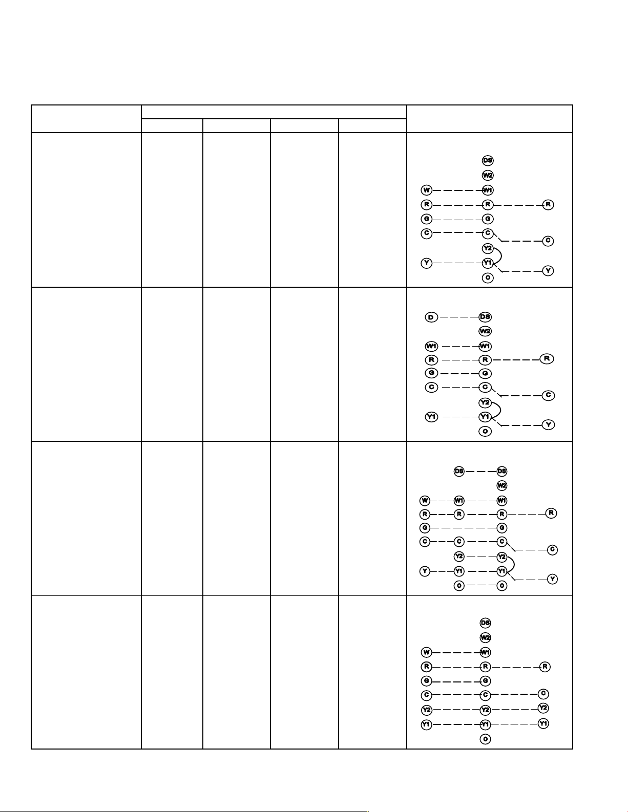
VIII− Field Wiring Applications and Jumper Settings
A−SureLight Board 49M59
TABLE 44
Field Wiring Applications
Thermostat
1 Heat / 1 Cool
NOTE − Use dip switch
3 to set second−stage
heat ON delay.
ON−10 minutes.
OFF−15 minutes.
51M26 SignatureStat
NOTE − Use dip
switch 3 to set second−stage heat ON
delay.
ON−10 minutes.
OFF−15 minutes.
Jumper Settings (See figure 4)
E20 W915 W914 W951
SINGLE Intact Intact Intact
SINGLE Intact Cut Intact
Wiring Connections
S1
T’STAT
51M26
T’STAT
CONTROL
TERM. STRIP
CONTROL
TERM. STRIP
OUTDOOR
UNIT
HSXB15
(LSOM)
OUTDOOR
UNIT
HSXB15
(LSOM)
1 Heat / 1 Cool
with CCB1
NOTE − Use dip switch
3 to set second−stage
heat ON delay.
ON−10 minutes.
OFF−15 minutes.
1 Heat / 2 Cool
NOTE − Use dip switch
3 to set second−stage
heat ON delay.
ON−10 minutes.
OFF−15 minutes.
SINGLE Intact Cut Intact
SINGLE Cut Intact Intact
S1
T’STAT
S1
T’STAT
CCB1
CONTROL
TERM. STRIP
CONTROL
TERM. STRIP
OUTDOOR
UNIT
HSXB15
(LSOM)
OUTDOOR
UNIT
HSXA19
(LSOM)
Page 86
Page 87

TABLE 45
Field Wiring Applications (Continued)
Thermostat
1 Heat / 2 Cool
E20 W915 W914 W951
SINGLE Cut Cut Intact
Jumper Settings (See figure 4)
with CCB1
NOTE − Use dip switch
3 to set second−stage
heat ON delay.
ON−10 minutes.
OFF−15 minutes.
2 Heat / 2 Cool TWO Cut Intact Intact
Wiring Connections
S1
S1
CCB1
CONTROL
TERM. STRIP
T’STAT
T’STAT
CONTROL
TERM. STRIP
OUTDOOR
UNIT
HSXA19
(LSOM)
OUTDOOR
UNIT
HSXA19
(LSOM)
51M27 SignatureStat TWO Cut Cut Intact
2 Heat / 2 Cool
TWO Cut Cut Intact
with CCB1
51M27
S1
T’STAT
CONTROL
TERM. STRIP
CCB1
CONTROL
TERM. STRIP
OUTDOOR
UNIT
HSXA19
(LSOM)
OUTDOOR
UNIT
HSXA19
(LSOM)
Page 87
Page 88

TABLE 46
Field Wiring Applications (Continued)
Thermostat
E20 W915 W914 W951
Jumper Settings (See figure 4)
2 Heat / 1 Cool TWO Intact Intact Intact
FM21 Heat Pump / 1
SINGLE Intact Intact Cut
Cool
Wiring Connections
S1
T’STAT
*Disconnect existing
furnace transformer
and replace with 75VA,
24V transformer if defrost option to be used.
75VA, 24V
TRANSFORMER*
NOTE − Wiring connections to outdoor unit and
thermostat made at
FM21 control board per
FM21 instructions.
CONTROL
TERM. STRIP
HSXB15
(LSOM)
CONTROL
TERM. STRIP
OUTDOOR
UNIT
FM21
NOTE −
Remove
Y1/Y2 jumper
for two−stage
cooling.
Page 88
Page 89

B−SureLight Board 100870
Thermostat
1Heat / 1 Cool
NOTE − Use DIP
switch 2 to set
second−stage
heat ON delay.
OFF−10 minutes.
ON−15 minutes.
DIP Switch 1
ON Intact Intact Intact
TABLE 47
Field Wiring Applications (Continued)
Jumper Settings (See figure 5)
W915
Two−Stage
Cooling
W914 Dehu-
midification
or Harmony
III
W951
Heat Pumps
Wiring Connections
S1
T’STAT
CONTROL
TERM. STRIP
OUTDOOR
UNIT
1 Heat / 2 Cool
NOTE − Use DIP
switch 2 to set
second−stage
heat ON delay.
OFF−10 minutes.
ON−15 minutes.
1 Heat / 2 Cool
with t’stat with
humidity control
NOTE − Use DIP
switch 2 to set
second−stage
heat ON delay.
OFF−10 minutes.
ON−15 minutes.
ON Cut Intact Intact
ON Cut Cut Intact
S1
T’STAT
S1
T’STAT
CONTROL
TERM. STRIP
CONTROL
TERM. STRIP
OUTDOOR
UNIT
OUTDOOR
UNIT
Page 89
Page 90

TABLE 48
Field Wiring Applications (Continued)
Jumper Settings (See figure 5)
Thermostat
DIP Switch 1
W915
Two−Stage
Cooling
W914 Dehumidification
or Harmony
W951
Heat Pumps
III
2 Heat / 2 Cool OFF Cut Intact Intact
Wiring Connections
S1
T’STAT
CONTROL
TERM. STRIP
OUTDOOR
UNIT
2 Heat / 2 Cool
OFF Cut Cut Intact
with t’stat with
humidity control
2 Heat / 1 Cool OFF Intact Intact Intact
S1
T’STAT
S1
T’STAT
CONTROL
TERM. STRIP
CONTROL
TERM. STRIP
OUTDOOR
UNIT
OUTDOOR
UNIT
Page 90
Page 91

IX− SURELIGHT® CONTROL TROUBLESHOOTING GUIDE
code
LED#2 Slow Flash
ACTION 1
ducer does not energize
ducer does not energize
120V field connection.
p
on operation
A−SureLight Board 49M59
UPON INITIAL POWER UP, REMOVE ALL THERMOSTAT DEMANDS TO THE UNIT
PROBLEM: 1 UNIT FAILS TO OPERATE IN THE COOLING, HEATING, OR CONTINUOUS FAN MODE
Condition Possible Cause Corrective Action / Comments
1.1
− Both diagnostic lights fail to light up.
Main voltage 120V not supplied to unit.
1.1.1
ACTION 1 − Check 120V main voltage.
Determine cause of main power failure.
LED#1−Off
LED#2−Off
1.2
− Diagnostic lights flash the roll−out
.
code.
LED#1−On,
LED#2−Slow Flash
1.3
− On initial power−up the comb. air in.
.
− Diagnostic lights flash the reverse
polarity code.
1.1.2
Miswiring of furnace or improper connections.
1.1.3
Blown fuse
1.1.4
Door interlock switch failure.
1.1.5
Transformer Failure.
1.1.6
Failed control board.
1.2.1
Roll−out switch open.
1.2.2
Roll−out switch failure.
1.2.3
Miswiring or improper connections at
roll−out switch.
1.2.4
9 pin connector failure
1.3.1
120V main power polarity reversed.
ACTION 1 − Check for correct wiring of 120V to
power make up box and transformer.
ACTION 2 − Check 24V wiring to control board.
ACTION 1 − Replace fuse.
ACTION 2 − If fuse still blows, check for short.
ACTION 1 − Check that door switch is activated
when door is closed.
ACTION 2 − Check wire connections to switch, replace loose connectors.
ACTION 3 − Check continuity of switch in closed
position. Replace if defective.
ACTION 1 − Check that transformer output is
24V. Replace if defective.
ACTION 1 − If all the above items have been
checked, replace board.
ACTION 1 − Manually reset the roll−out switch
by pushing the top button.
ACTION 2 − Determine the cause of the roll−out
switch activation before leaving furnace.
ACTION 1 − Check continuity across roll−out
switch. Replace roll−out switch if switch is reset
but does not have continuity.
− Check wiring connections to switch.
ACTION 1 − Check 9−pin connector for proper
connection to control board.
ACTION 2 − Check continuity of the multi plug
pin.
ACTION 1 − Check the 120V has line and neutral
correctly input into control.
ACTION 2 − Reverse the line and neutral at the
120V field connection.
LED#1−Fast Flash,
LED#2−Slow Flash.
− On initial power up the combustion
air inducer does not energize.
− Diagnostic lights flash normal power
eration.
on o
LED#1−Slow Flash
LED#2−Slow Flash
1.4
1.4.1
Open combustion air inducer motor
circuit.
ACTION 1 − Check for 120V to combustion air
inducer. If no power, check wire and connections.
.
1.4.2
Failed combustion air inducer motor.
ACTION 1 − If power is present at blower, replace
blower.
Page 91
Page 92

PROBLEM 1: UNIT FAILS TO OPERATE IN THE COOLING, HEATING, OR CONTINUOUS FAN MODE
g
LED#2 Alternating Fast Flash
gg
Condition Possible Cause Corrective Action / Comments
1.5
− Diagnostic lights flash the improper
main ground.
LED#1−Alternating Fast Flash
LED#2−Alternating Fast Flash
1.5.1
Improper ground to the unit.
1.5.2
6−Pin connector is improperly
attached to the circuit board.
1.5.3
Line voltage is below 75V.
1.5.4
Open ignitor circuit.
1.5.5
Broken or failed ignitor.
ACTION 1 − Check that the unit is properly
ground.
ACTION 2 − Install a proper main ground to the
unit
ACTION 1 − Check 6−pin connector for proper
installation. Correctly insert connector into control.
ACTION 1 − Check that the line voltage is above
75V. Determine cause of voltage drop and supply
correct voltage to the control.
ACTION 1 − Check for correct wiring and loose
connections in the ignitor circuit. Check mult−plug
connections for correct installation.
ACTION 1 − Unplug ignitor and read resistance
across ignitor. If resistance does not read between 10.9 and 19.7 ohms, replace the ignitor.
PROBLEM 2: UNIT FAILS TO FIRE IN THE HEATING MODE, COMBUSTION AIR BLOWER DOES NOT
ENERGIZE
Condition Possible Cause Corrective Action / Comments
2.1
− Unit operates with a cooling or contin-
uous fan demand.
− Combustion air inducer will not start
with a Heating demand.
− Diagnostic lights flash the limit failure
mode.
LED#1−Slow Flash,
LED#2−On
2.1.1
Primary, secondary or backup secon-
dary (if equipped ) limit open.
2.1.2
Miswiring of furnace or improper
connections at limit switch(es).
ACTION 1 − Check continuity across switch(es).
Switches reset automatically upon cool down.
ACTION 2 − Check for restrictions on blower inlet
air (including filter) and outlet air. Determine
cause for limit activation before placing unit back
in operation.
ACTION 1 − Check for correct wiring and loose
connections. Correct wiring and/or replace any
loose connections.
2.2
− Unit operates with a cooling and continuous fan demand.
− Combustion air inducer will not start
with a Heating demand.
− Diagnostic lights flash the pressure
switch failure code.
LED#1−Off,
LED#2−Slow Flash
2.2.1
Miswiring of furnace or improper
connections to combustion air
inducer.
2.2.2
Prove switch stuck closed.
ACTION 1 − Check for correct wiring and loose
connections. Correct wiring and/or replace any
loose connections.
ACTION 1 − Check that the prove switch is open
without the combustion air inducer operating. Replace if defective.
Page 92
Page 93

PROBLEM 2: UNIT FAILS TO FIRE IN THE HEATING MODE, COMBUSTION AIR INDUCER DOES
switch failure code 2.5 minutes after
g
LED#1 Off
NOT ENERGIZE (CONT.).
Condition Possible Cause Corrective Action/Comments
2.3
− Unit operates with a cooling and con-
tinuous fan demand.
− Combustion air inducer will not start
with a Heating demand.
− Diagnostic lights flash the pressure
Miswiring of furnace or improper
connections to combustion air induc-
2.3.1
ACTION 1 − Check for correct wiring and loose
connections. Correct wiring and/or replace any
loose connections.
er.
switch failure code 2.5 minutes after
heating demand.
ACTION 1 − If there is 120V to combustion air inducer and it does not operate, replace combustion air inducer.
LED#1−Off,
2.3.2
Combustion air inducer failure.
LED#2−Slow Flash
PROBLEM 3: UNIT FAILS TO FIRE IN THE HEATING MODE, COMBUSTION AIR INDUCER
ENERGIZES, IGNITOR IS NOT ENERGIZED.
Condition Possible Cause Corrective Action/Comments
3.1
− Unit operates with a cooling and
continuous fan demand.
− Combustion air inducer energizes
with a heating demand.
− Diagnostic lights flash the pressure
switch failure code 2.5 minutes after
heating demand.
LED#1−Off
LED#2−Slow Flash
Prove switch does not close due to
incorrect routing of the pressure
Prove switch does not close due to
obstructions in the pressure lines.
Prove switch lines damaged
Condensate in prove switch line.
Prove switch does not close due to a
low differential pressure across the
Wrong prove switch installed in the
unit, or prove switch is out of
Miswiring of furnace or improper
connections at prove switch.
Prove switch failure.
3.1.1
switch lines.
3.1.2
3.1.3
3.1.4
3.1.5
prove switch.
3.1.6
calibration.
3.1.7
3.1.8
ACTION 1 − Check that the prove switch lines are
correctly routed. Correctly route pressure switch
lines.
ACTION 1 − Remove any obstructions from the
the pressure lines and/or taps.
ACTION 1 − Check prove switch lines for leaks.
Replace any broken lines.
ACTION 1 − Check prove switch lines for condensate. Remove condensate from lines.
ACTION 1 − Check the differential pressure
across the prove switch. This pressure should
exceed the set point listed on the switch.
ACTION 2 − Check for restricted inlet vent. Remove all blockage.
ACTION 3 − Check for proper vent sizing and
run length.
ACTION 1 − Check that the proper prove switch
is installed in the unit. Replace prove switch if
necessary.
ACTION 1 − Check for correct wiring and loose
connections. Correct wiring and/or replace any
loose connections.
ACTION 1 − If all the above modes of failure have
been checked, the prove switch may have failed.
Replace prove switch and determine if unit will
operate.
Page 93
Page 94

PROBLEM 4: UNIT FAILS TO FIRE IN THE HEATING MODE, COMBUSTION AIR BLOWER
5.1
LED#1 Off
ignite code.
ENERGIZES, IGNITOR IS ENERGIZED.
Condition Possible Cause Corrective Action/Comments
4.1
− Unit operates with a cooling and
continuous fan demand.
− Combustion air inducer energizes
with Heating demand.
− Ignitor is energized but unit fails to
light.
LED#1−Alternating Slow Flash
LED#2−Alternating Slow Flash
4.1.1
Check that gas is being supplied to
the unit.
4.1.2
Miswiring of gas valve or loose-
connections at multi−pin control amp
plugs or valve.
4.1.3
Defective gas valve or ignition
control.
ACTION 1 − Check line pressure at the gas valve.
Pressure should not exceed 13" WC for both natural and propane. Line pressure should read a
minimum 4.5" WC for natural and 8.0"WC for propane.
ACTION 1 − Check for correct wiring and loose
connections. Correct wiring and/or replace any
loose connections.
ACTION 1 − Check that 24V is supplied to the gas
valve approximately 35 seconds after heat demand is initiated.
ACTION 2 − Replace the valve if 24V is supplied
but valve does not open.
ACTION 3 − Replace the control board if 24V is
not supplied to valve.
PROBLEM 5: BURNERS LIGHT WITH A HEATING DEMAND BUT UNIT SHUTS DOWN
PREMATURELY
Condition Possible Cause Corrective Action/Comments
ACTION 1 − Check for restricted intake and ex-
haust vent. Remove all blockage.
ACTION 2: Check for proper vent sizing. See
installation instructions.
ACTION 1 − Check vent termination kit installed.
See Placement and Installation section.
ACTION 1 − Check condensate line for proper
vent slope, and any blockage. Condensate
should flow freely during operation of furnace.
Repair or replace any improperly installed condensate lines.
ACTION 1 − Check for restricted intake and exhaust. Remove all blockage.
ACTION 2: Check for proper vent sizing. See
installation instructions.
ACTION 1 − Check that sensor is properly located and that the sense wire is properly attached to both the sensor and the control.
ACTION 1 − Check for a broken sensor.
ACTION 2 − Test continuity across the sense
wire. If wire or sensor are damaged replace the
component.
ACTION 1 − Check for resistance between the
sensor rod and the unit ground.
ACTION 2 − Check for resistance between the
sensor wire and the unit ground.
ACTION 3 − Correct any shorts found in circuit.
ACTION 1 − Check the microamp signal from
the burner flame. If the microamp signal is below normal, check the sense rod for proper
location or contamination.
ACTION 2 − Replace, clean, or relocate flame
sense rod. If rod is to be cleaned, use steel
wool or replace sensor. DO NOT CLEAN ROD
WITH SAND PAPER. SAND PAPER WILL
CONTRIBUTE TO THE CONTAMINATION
PROBLEM. NOTE: Do not attempt to bend
sense rod.
5.1
− Burners fire with a heating demand.
− Burners light but unit shuts off prior
to satisfying T−stat demand.
− Diagnostic lights flash the pressure
switch code.
LED#1−Off
LED#2−Slow Flash
5.2
− Combustion air inducer energizes
with a heating demand.
− Burners light but fail to stay lit.
− After 5 tries the control diagnostics
flash the watchguard burners failed to
ignite code.
LED#1−Alternating Slow Flash
LED#2−Alternating Slow Flash
5.1.1
Low pressure differential at the prove
switch.
5.1.2
Wrong concentric vent kit used for
terminating the unit.
5.1.3
Condensate drain line is not draining
properly.
5.1.4
Low pressure differential at the prove
switch.
5.2.1
Sensor or sense wire is improperly
installed.
5.2.2
Sensor or sense wire is broken.
5.2.3
Sensor or sensor wire is grounded to
the unit.
5.2.4
Control does not sense flame.
Page 94
Page 95

PROBLEM 5: BURNERS LIGHT WITH HEATING DEMAND BUT UNIT SHUTS DOWN
ure.
flame failure.
Condition Possible Cause Corrective Action/Comments
5.3
− Combustion air inducer energizes
with a heating demand.
− Burners light.
− Roll−out switch trips during the
heating demand.
− Diagnostic lights flash roll−out fail-
ure.
LED#1−On
LED#2−Slow Flash
PREMATURELY (CONT.)
5.3.1
Unit is firing above 100% of the
nameplate input.
5.3.2
Gas orifices leak at the manifold
connection.
5.3.3
Air leakage at the connections
between the primary heat exchanger,
secondary heat exchanger, and
combustion air blower.
ACTION 1 − Check that the manifold pressure
matches value listed on nameplate. See installation instructions for proper procedure.
ACTION 2 − Verify that the installed orifice size
match the size listed on the nameplate or installation instructions.
ACTION 3 − Check gas valve sensing hose to insure no leaks are present.
ACTION 4 − Check the input rate to verify rate
matches value listed on nameplate.
ACTION 1 − Tighten orifice until leak is sealed.
NOTE: Be careful not to strip orifice threads.
ACTION 2 − Check for gas leakage at the
threaded orifice connection. Use approved method for leak detection (see unit instructions).
ACTION 1 − Check for air leakage at all joints in
the heat exchanger assembly. Condition will
cause high CO2 with high CO.
ACTION 2 − Seal leakage if possible, replace
heat exchanger if necessary, tag and return heat
exchanger to proper Lennox personnel.
5.4
− Combustion air inducer energizes
with a heating demand.
− Burners light roughly and the unit
fails to stay lit.
− Diagnostic lights flash watchguard
flame failure.
LED#1−Alternating Slow Flash
LED#2−Alternating Slow Flash
5.3.4
Insufficient flow through the heat
exchanger caused by a sooted or
restricted heat exchanger.
5.3.5
Burners are not properly located in
the burner box.
5.4.1
Recirculation of flue gases. This
condition causes rough ignitions and
operation. Problem is characterized
by nuisance flame failures.
5.4.2
Improper burner cross−overs
ACTION 1 − Check for sooting deposits or other
restrictions in the heat exchanger assembly.
Clean assembly as outlined in instruction manual.
ACTION 2 − Check for proper combustion.
ACTION 1 − Check that the burners are firing into
the center of the heat exchanger openings. Correct the location of the burners if necessary.
ACTION 1 − Check for proper flow of exhaust
gases away from intake vent. Remove any obstacles in front of the intake and exhaust vent
which would cause recirculation.
ACTION 2 − Check for correct intake and exhaust
vent installation. See instructions
ACTION 1 − Remove burner and inspect the
cross−overs for burrs, or any restriction or if
crossover is warped. Remove restriction or replace burners.
Page 95
Page 96

PROBLEM 6: CONTROL SIGNALS LOW FLAME SENSE DURING HEATING MODE
code
Condition Possible Cause Corrective Action/Comments
6.0
− Unit operates correctly but the diagnostic lights flash low flame sense
Sensor rod is improperly located on
6.1.1
the burner.
ACTION 1 − Check the sensor rod for proper location on the burner. Properly locate the sensor rod
or replace if rod cannot be located correctly.
.
ACTION 1 − Check sensor rod for contamination
or coated surface. Clean the sensor rod with steel
wool or replace sensor. DO NOT USE SAND PAPER TO CLEAN ROD. SAND PAPER WILL
CONTRIBUTE TO THE CONTAMINATION
PROBLEM.
LED#1−Slow Flash
LED#2−Fast Flash
6.1.2
Sensor rod is contaminated.
PROBLEM 7: INDOOR BLOWER FAILS TO OPERATE IN COOLING, HEATING, OR CONTINUOUS
FAN MODE
Condition Possible Cause Corrective Action/Comments
7.0
− Indoor blower fails to operate in
continuous fan, cooling, or heating
mode.
Miswiring of furnace or improper
connections at control or indoor blow-
120V is not being supplied to the
indoor air blower or blower motor fail-
7.1.1
er motor.
7.1.2
ure.
ACTION 1− Correct wiring and/or replace any
loose connections. Check for correct wiring and
loose connections.
ACTION 1 − Check for 120V at the various calls
for indoor blower by energizing "Y", "G", and "W"
individually on the low voltage terminal strip. Note
that when "W’ is energized, the blower is delayed
45 seconds. If there is 120V to each motor tap but
the blower does not operate, replace the motor.
Condition Possible Cause Corrective Action/Comments
8.0
− AM radio interference.
7.1.3
Defective control board
7.1.4
Defective run capacitor
ACTION 1 − If there is not 120V when "Y", "G", or
"W" is energized, replace the control.
ACTION 1 − Replace capacitor
PROBLEM 8: RF STATIC DURING TIME FOR IGNITION
8.1.2
Ignitor operation
ACTION 1 − Call Technical Support, Dallas.
Page 96
Page 97

B−SureLight Board 100870
Diagnostic light flashes the reverse
ACTION 1
120V h
l
120V main power polarity reversed.
circuit fault
Two Stage Variable Speed Control Board 100870
UPON INITIAL POWER UP, REMOVE ALL THERMOSTAT DEMANDS TO THE UNIT
PROBLEM: 1 UNIT FAILS TO OPERATE IN THE COOLING, HEATING, OR CONTINUOUS FAN MODE
Flash Code
LED X + Y
1.1
− Diagnostic lights fail to light up.
Main voltage 120V not supplied to unit.
Possible Cause Corrective Action / Comments
1.1.1
ACTION 1 − Check 120V main voltage.
Determine cause of main power failure.
LED OFF
1.2
polarity code.
LED 5 + 4
1.3
− Diagnostic light flash the improper
main ground.
1.1.2
Miswiring of furnace or improper connections.
1.1.3
Circuit breaker tripped or fails to
close.
1.1.4
Door interlock switch failure.
1.1.5
Transformer Failure.
1.1.6
Failed control board.
1.2.1
120V main power polarity reversed.
1.3.1
Improper ground to the unit.
ACTION 1 − Check for correct wiring of 120V to
power make up box and transformer.
ACTION 2 − Check 24V wiring to control board.
ACTION 1 − Replace circuit breaker if it is reset
but does not have continuity.
ACTION 2 − If circuit breaker still trips, check for
short.
ACTION 1 − Check that door switch is activated
when door is closed.
ACTION 2 − Check wire connections to switch, replace loose connectors.
ACTION 3 − Check continuity of switch in closed
position. Replace if defective.
ACTION 1 − Check that transformer output is
24V. Replace if defective.
ACTION 1 − If all the above items have been
checked, replace board.
−
correctly input into control.
− Check the
ACTION 2 − Reverse the line and neutral at the
120V field connection.
ACTION 1 − Check that the unit is properly ground.
ACTION 2 − Install a proper main ground to the unit
as line and neutra
LED 5 + 3
1.4
− Diagnostic light flashes ignitor
circuit fault.
LED 4 + 7
1.5
− Diagnostic light flashes low
line voltage
LED 4 + 8
1.4.1
.
Open ignitor circuit.
1.4.2
Broken or failed ignitor.
1.5.1
Line voltage is below 90V.
Page 97
ACTION 1 − Check for correct wiring and loose
connections in the ignitor circuit. Check mult−plug
connections for correct installation.
ACTION 1 − Unplug ignitor and read resistance
across ignitor. If resistance does not read between
25 and 47 ohms, replace the ignitor.
ACTION 1 − Check that the line voltage is above
90V. Determine cause of voltage drop and supply
correct voltage to the control.
Page 98

PROBLEM 2: UNIT FAILS TO FIRE IN THE HEATING MODE, COMBUSTION AIR BLOWER DOES NOT
g
g
Diagnostic lights flash the pressure
ENERGIZE
Flash Code
LED X + Y
2.1
Unit operates with a cooling or
continuous fan demand.
Combustion air inducer will not start
with a Heating demand.
Diagnostic lights flash the limit failure
mode.
LED 3 + 1
2.2
Unit operates with a cooling and
continuous fan demand.
Combustion air inducer will not start
with a Heating demand.
Diagnostic lights flash the pressure
switch failure code.
LED 2 +4
2.3
Unit operates with a cooling or
continuous fan demand.
Combustion air inducer will not start
with a Heating demand.
Diagnostic lights flash the open
rollout failure mode.
Possible Cause
2.1.1
Primary Limit or secondary limit
(if equipped ) open.
2.1.2
Miswiring of furnace or improper con-
nections at limit switch(es).
2.2.1
Miswiring of furnace or improper con-
nections to combustion air inducer.
2.2.2
Prove switch stuck closed.
2.3.1
Rollout Switch Open.
Corrective Action / Comments
ACTION 1 − Check continuity across switch(es).
Switches reset automatically upon cool down.
ACTION 2 − Check for restrictions on blower inlet
air (including filter) and outlet air. Determine
cause for limit activation before placing unit back
in operation.
ACTION 1 − Check for correct wiring and loose
connections. Correct wiring and/or replace any
loose connections.
ACTION 1 − Check for correct wiring and loose
connections. Correct wiring and/or replace any
loose connections.
ACTION 1 − Check that the prove switch is open
without the combustion air inducer operating. Replace if defective.
ACTION 1 − Check continuity across rollout
switches. Rollout switches must be manually reset.
ACTION 2 − Look for restrictions in vent pipe or
combustion air inlet or heat exchanger. Determine cause before placing unit in operation.
LED 5 + 1
PROBLEM 3: UNIT FAILS TO FIRE IN THE HEATING MODE, COMBUSTION AIR INDUCER DOES
NOT ENERGIZE
Condition Possible Cause Corrective Action/Comments
3.3
Unit operates with a cooling and
continuous fan demand.
Combustion air inducer will not start
with a Heating demand.
nostic lights flash the pressure
Dia
switch failure code 2.5 minutes after
heating demand.
LED 2 + 3
Miswiring of furnace or improper con-
nections to combustion air inducer.
Combustion air inducer failure.
3.3.1
3.3.2
ACTION 1 − Check for correct wiring and loose
connections. Correct wiring and/or replace any
loose connections.
ACTION 1 − If there is 120V to combustion air inducer and it does not operate, replace combustion air inducer.
Page 98
Page 99

PROBLEM 4: UNIT FAILS TO FIRE IN THE HEATING MODE, COMBUSTION AIR INDUCER
g
ENERGIZES, IGNITOR IS NOT ENERGIZED.
Flash Code
LED X + Y
4.1
− Unit operates with a cooling and
continuous fan demand.
− Combustion air inducer energizes
with a heating demand.
− Diagnostic lights flash the pressure
switch failure code 2.5 minutes after
heating demand.
LED 2 + 3
Prove switch does not close due to
Prove switch does not close due to
incorrect routing of the prove switch
Prove switch does not close due to
obstructions in the prove switch line.
Condensate in prove switch line.
Prove switch does not close due to a
low differential pressure across the
Wrong prove switch installed in the
unit, or prove switch is out of calibra-
Miswiring of furnace or improper con-
Possible Cause Corrective Action/Comments
4.1.1
obstruction in vent pipe.
ACTION 1 − Check for restricted vent. Remove all
blockage.
ACTION 2: Check for proper vent sizing. See
installation instructions.
4.1.2
ACTION 1 − Check that the prove switch line is
correctly routed. Correctly route prove switch
line.
line.
4.1.3
4.1.4
Prove switch line damaged
4.1.5
4.1.6
prove switch.
ACTION 1 − Remove any obstructions from the
the prove switch line and/or taps.
ACTION 1 − Check prove switch line for leaks.
Replace broken line if required.
ACTION 1 − Check prove switch line for condensate. Remove condensate from line.
ACTION 1 − Check the differential pressure
across the prove switch. This pressure should
exceed the set point listed on the switch.
ACTION 2 − Check for restricted inlet vent. Remove all blockage.
ACTION 3 − Check for proper vent sizing and
run length. See installation instructions.
4.1.7
ACTION 1 − Check that the correct prove switch
is installed in the unit. Replace prove switch if
necessary.
tion.
4.1.8
nections at prove switch.
4.1.9
Prove switch failure.
ACTION 1 − Check for correct wiring and loose
connections. Correct wiring and/or replace any
loose connections.
ACTION 1 − If all the above modes of failure have
been checked, the prove switch may have failed.
Replace prove switch and determine if unit will
operate.
Page 99
Page 100

PROBLEM 5: UNIT FIRES ON LOW FIRE, FAILS TO GO TO HIGH FIRE OPERATION
Flash Code
LED X + Y
5.1
− Unit light s normally during low fire
− Call for high fire inducer switches to
high fire for 10 seconds then back to
low fire.
− Diagnostic lights flash the high
pressure switch failure to close.
LED 2 + 5
Possible Cause Corrective Action/Comments
5.1.1
Prove switch does not close due to
obstruction in vent pipe.
5.1.2
Prove switch does not close due to
incorrect routing of the prove switch
line.
5.1.3
Prove switch does not close due to
obstructions in the prove switch line.
5.1.4
Prove switch line damaged
5.1.5
Condensate in prove switch line.
5.1.6
Prove switch does not close due to a
low differential prove across the
prove switch.
5.1.7
Wrong prove switch installed in the
unit, or prove switch is out of calibra-
tion.
5.1.8
Miswiring of furnace or improper con-
nections at prove switch.
5.1.9
Prove switch failure.
ACTION 1 − Check for restricted vent. Remove all
blockage.
ACTION 2: Check for proper vent sizing. See
installation instructions.
ACTION 1 − Check that the prove switch line is
correctly routed. Correctly route prove switch
line.
ACTION 1 − Remove any obstructions from the
the prove switch line and/or taps.
ACTION 1 − Check prove switch line for leaks.
Replace broken line if required.
ACTION 1 − Check prove switch line for condensate. Remove condensate from line.
ACTION 1 − Check the differential pressure
across the prove switch. This pressure should
exceed the set point listed on the switch.
ACTION 2 − Check for restricted inlet vent. Remove all blockage.
ACTION 3 − Check for proper vent sizing and
run length. See installation instructions.
ACTION 1 − Check that the correct prove switch
is installed in the unit. Replace prove switch if
necessary.
ACTION 1 − Check for correct wiring and loose
connections. Correct wiring and/or replace any
loose connections.
ACTION 1 − If all the above modes of failure have
been checked, the prove switch may have failed.
Replace prove switch and determine if unit will
operate.
Page 100
 Loading...