

Page 1
Page 1
© 2003 Lennox Industries Inc.
Corp. 0124−L11
G60UHV(X)
Service Literature
Revised 1−2009
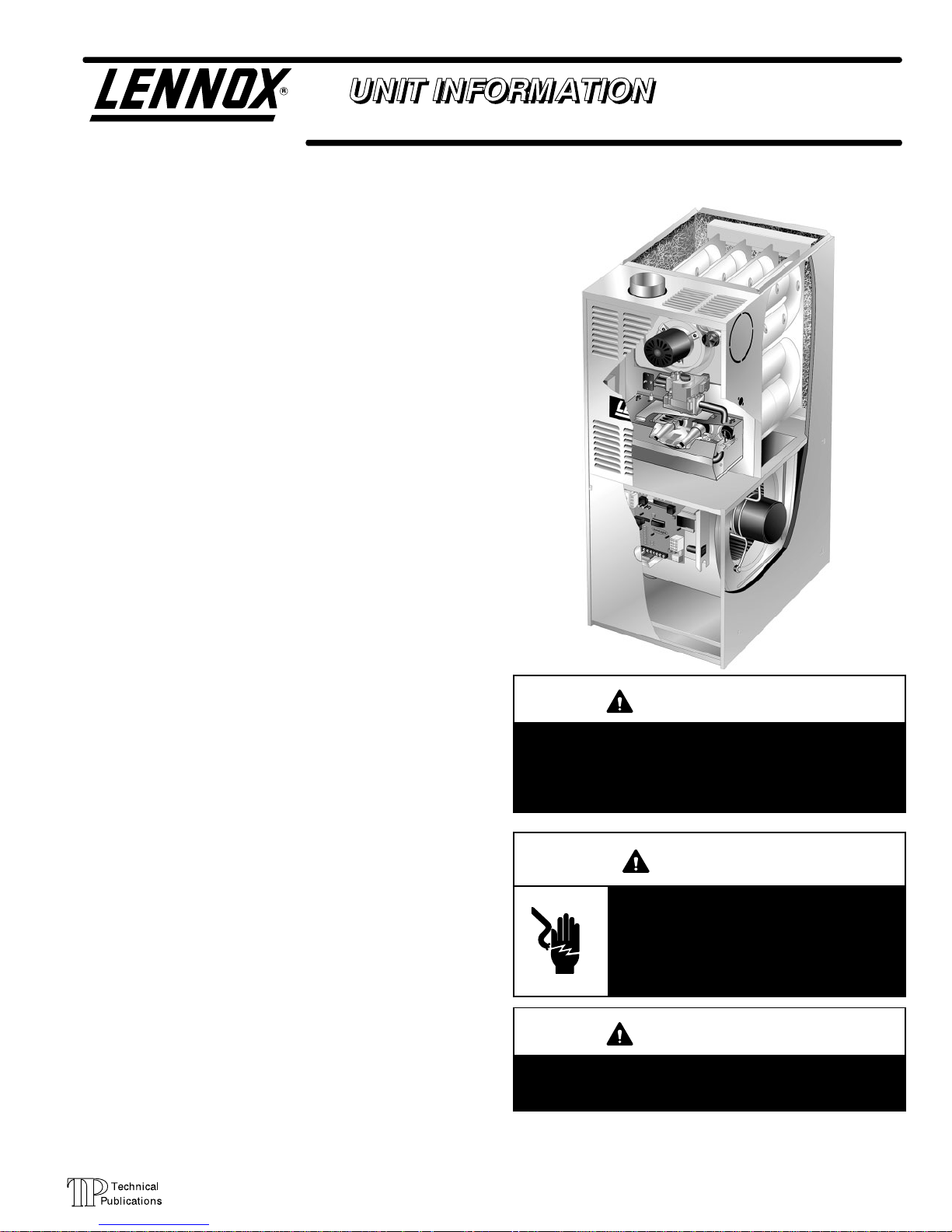
G60UHV(X) SERIES UNITS
G60UHV(X) series units are mid−efficiency gas furnaces
used for upflow or horizontal applications only, manufactured with Lennox Duralok Plus heat exchangers formed of
aluminized steel. G60UH(X) units are available in heating
capacities of 66,000 to 132,000 Btuh and cooling applications up to 5 tons. Refer to Engineering Handbook for proper sizing.
Units are factory equipped for use with natural gas. Kits are
available for conversion to LPG operation. G60UH(X) model
units are equipped with the Two−Stage / Variable Speed Integrated SureLight control. G60UH(X) unit meets the California Nitrogen Oxides (NO
x
) Standards and California Seasonal Efficiency requirements. All units use a redundant gas
valve to assure safety shut−off as required by C.S.A.
All specifications in this manual are subject to change. Procedures outlined in this manual are presented as a recommendation only and do not supersede or replace local or
state codes. In the absence of local or state codes, the
guidelines and procedures outlined in this manual (except
where noted) are recommendations only and do not constitute code.
TABLE OF CONTENTS
Introduction Page 1. . . . . . . . . . . . . . . . . . . . . . . . . . . . . . .
Specifications Page 2. . . . . . . . . . . . . . . . . . . . . . . . . . . . .
Blower Data Page 4. . . . . . . . . . . . . . . . . . . . . . . . . . . . . .
High Altitude Page 7. . . . . . . . . . . . . . . . . . . . . . . . . . . . . .
I Unit Components Page 9. . . . . . . . . . . . . . . . . . . . . . . .
II Installation Page 32. . . . . . . . . . . . . . . . . . . . . . . . . . . .
III Start Up Page 32. . . . . . . . . . . . . . . . . . . . . . . . . . . . . . .
IV Heating System Service Checks Page 33. . . . . . . . .
V Typical Operating Characteristics Page 35. . . . . . . . .
VI Maintenance Page 36. . . . . . . . . . . . . . . . . . . . . . . . . .
VII Wiring and Sequence of Operation Page 38. . . . . .
VIII Field Wiring and Jumper Settings Page 53. . . . . . .
IX Troubleshooting Page 58. . . . . . . . . . . . . . . . . . . . . . .
IMPORTANT
Improper installation, adjustment, alteration, service
or maintenance can cause property damage, personal injury or loss of life. Installation and service must
be performed by a qualified installer, service agency
or the gas supplier.
WARNING
Electric shock hazard. Can cause injury
or death. Before attempting to perform
any service or maintenance, turn the
electrical power to unit OFF at disconnect switch(es). Unit may have multiple
power supplies.
WARNING
Sharp edges.
Be careful when servicing unit to avoid sharp edges
which may result in personal injury.
Page 2
Page 2
SPECIFICATIONS
Gas
Heating
Performance
ModelNo. G60UHV−36A−070 G60UHV−36B−090 G60UHV−60C−090
Low NOx Model No. G60UHV−36A−070X − − − G60UHV−60C−090X
Input− Btuh (kW) low fire 45,000 (13.2) 60,000 (17.6) 60,000 (17.6)
Output− Btuh (kW) low fire 36,000 (10.5) 48,000 (14.1) 48,000 (14.1)
Input− Btuh (kW) high fire 66,000 (19.3) 88,000 (5.8) 88,000 (25.8)
Output− Btuh (kW) high fire 54,000 (15.8) 72,000 (21.0) 72,000 (21.1)
AFUE 80.0% 80.0% 80.0%
California Seasonal Efficiency 77.2% 77.1% 76.8%
Highstatic(CSA)− in.w.g. (Pa) .80 (200) .80 (200) .80 (200)
Flue connection − in. (mm) round 4 (102) 4 (102) 4 (102)
GaspipesizeIPS− in. (mm) 1/2 (12.7) 1/2 (12.7) 1/2 (12.7)
Temperature rise range − F (C) low fire 20 − 50 (11 − 28) 20 − 50 (11 − 28) 15 − 45 (8 − 25)
Temperature rise range − F (C) high fire 40 − 70 (22 − 39) 40 − 70 (22 − 39) 30 − 60 (17 − 33)
Indoor
Blower
Wheelnominaldiameter xwidth −in. (mm) 10 x 8 (254 x 203) 10 x 8 (254 x 203) 11−1/2 x 10 (292 x 254)
Motoroutput − hp (W) 1/2 (373) 1/2 (373) 1 (746)
Tons(kW) ofadd-oncooling 2 − 3 (7.0 − 10.6) 2 − 3 (7.0 − 10.6) 4 − 5 (14.1 − 17.6)
Shippingweight − 1 package 137 (62) 154 (70) 172 (78)
Matching Coils Up−flow cased C33−18A−2F,
C33−24A−2F,
C33−30A−2F,
C33−36A−2F,
C33−38A−2F
C33−24B−2F,
C33−30B−2F,
C33−36B−2F,
C33−38B−2F,
C33−42B−2F,
C33−48B−2F
C33−36C−2F,
C33−48C−2F,
C33−50/60C−2F,
Horizontal CH33−18A−2F,
CH33−24/30A−2F,
CH33−36A−2F
CH33−36B−2F,
CH33−42B−2F,
CH33−44/48B−2F
CH33−36C−2F,
CH33−48C−2F,
CH33−50/60C−2F
Electricalcharacteristics 120 volts − 60 hertz − 1 phase (less than 12 amps)
OPTIONAL ACCESSORIES − MUST BE ORDERED EXTRA
Air Filter and Rack Kit
Number and size of filters
Horizontal (end) 87L95 − (1) 14 x 25 x 1 in.
(356 x 635 x 25 mm)
87L96 − (1) 18 x 25 x 1 in.
(457 x 635 x 25 mm)
87L97 − (1) 20 x 25 x 1 in.
(508 x 635 x 25 mm)
Side Return Single (44J22) or Ten Pack (66K63) − (1) 16 x 25 x 1 in. (406 x 635 x 25 mm)
EZ Filter Base Catalog Number − Shipping Weight 73P55 − 6 lbs. (3 kg) 73P56 − 7 lbs. (3 kg) 73P57 − 8 lbs. (4 kg)
Dimensions − H x W x D 4 x 14−1/4 x 28−5/8 in.
(102 x 362 x 727 mm)
4 x 17−5/8 x 28−5/8 in.
(102 x 448 x 727 mm)
4 x 21−5/8 x 28−5/8 in.
(102 x 549 x 727 mm)
Number and size of filter (field provided) 14 x 25 x 1 in. (356 x
635 x 25 mm)
16 x 25 x 1 in. (406 x
635 x 25 mm)
20 x 25 x 1 in. (508 x
635 x25 mm)
CCB1 Efficiency Plust Humidity Control System 35H00 35H00 35H00
High Altitude Pressure Switch Kit See Page 7
Horizontal Support Frame Kit − Shipping Weight 56J18 − 18 lbs. (8 kg) 56J18 − 18 lbs. (8 kg) 56J18 − 18 lbs. (8 kg)
LPG/Propane Kit See Page 7
RAB Return Air Base − − − − − − RAB60C (12M71)
Vent Adaptor − 6 in. 152 (mm) connection size 18M79 − 2 lbs. (1 kg) 18M79 − 2 lbs. (1 kg) 18M79 − 2 lbs. (1 kg)
Annual Fuel Utilization Efficiency based on DOE test procedures and according to FTC labeling regulations. Isolated combustion system rating for non-weatherized furnaces.
NOTE − Filters and provisions for mounting are not furnished and must be field provided.
The same C33 uncased models match the furnaces shown but require an optional adaptor base or field fabricated transition. See C33 coil bulletin for additional information.
Cleanable polyurethane frame type filter.
Not for use with RAB Return Air Base or with 60C and 60D size units with 2nd stage heating air flow requirements of 1800 cfm (850 L/s) or greater. See Blower Performance
Tables for additional information.
Page 3
Page 3
SPECIFICATIONS
Gas
Heating
Performance
ModelNo. G60UHV−60C−110 G60UHV−60D−135
Low NOx Model No. G60UHV−60C−110X − − −
Input− Btuh (kW) low fire 75,000 (22.0) 90,000 (26.4)
Output− Btuh (kW) low fire 60,000 (17.6) 72,000 (21.1)
Input− Btuh (kW) high fire 110,000 (32.2) 132,000 (38.7)
Output− Btuh (kW) high fire 90,000 (26.4) 108,000 (31.6)
AFUE 80.0% 80.0%
California Seasonal Efficiency 77.2% 77.5%
Highstatic(CSA)− in.w.g. (Pa) .80 (200) .80 (200)
Flue connection − in. (mm) round 4 (102) 4 (102)
GaspipesizeIPS− in. (mm) 1/2 (12.7) 1/2 (12.7)
Temperature rise range − F (C) low fire 25 − 55 (14 − 31) 25 − 55 (14 − 31)
Temperature rise range − F (C) high fire 35 − 65 (19 − 36) 45 − 75 (25 − 42)
Indoor
Blower
Wheelnominaldiameter xwidth −in. (mm) 11−1/2 x 10 (292 x 254) 11−1/2 x 10 (292 x 254)
Motoroutput − hp (W) 1 (746) 1 (746)
Tons(kW) ofadd-oncooling 4 − 5 (14.1 − 17.6) 4 − 5 (14.1 − 17.6)
Shippingweight − 1 package 184 (83) 198 (90)
Matching Coils
Up−flow cased
C33−36C−2F, C33−48C−2F,
C33−50/60C−2F,
C33−60D−2F, C33−62D−2F
Horizontal
CH33−36C−2F, CH33−48C−2F,
CH33−50/60C−2F
CH33−60D−2F, CH33−62D−2F
Electricalcharacteristics 120 volts − 60 hertz − 1 phase (less than 12 amps)
OPTIONAL ACCESSORIES − MUST BE ORDERED EXTRA
Air Filter and Rack Kit
Number and size of filters
Horizontal (end)
87L97
(1) 20 x 25 x 1 in. (508 x 635 x 25
mm)
87L98
(1) 25 x 25 x 1 in. (635 x 635 x 25
mm)
Side Return Single 44J22 or Ten Pack (66K63) − (1) 16 x 25 x 1 (406 x 635 x 25)
EZ Filter Base
Catalog Number − Shipping Weight 73P57 − 8 lbs. (4 kg) 73P58 − 10 lbs. (5 kg)
Dimensions − H x W x D
4 x 21−5/8 x 28−5/8 in.
(102 x 549 x 727 mm)
4 x 24−5/8 x 28−5/8 in.
(102 x 625 x 727 mm)
Number and size of field provided filter (1) 20 x 25 x 1 in. (508 x 635 x25 mm)
(1) 24 x 24 x 1 in. (610 x 610 x 25
mm)
CCB1 Efficiency Plust Humidity Control System 35H00 35H00
High Altitude Pressure Switch Kit See Page 7
Horizontal Support Frame Kit − Shipping Weight 56J18 − 18 lbs. (8 kg) 56J18 − 18 lbs. (8 kg)
LPG/Propane Kit See Page 7
RAB Return Air Base RAB60C (12M71) RAB60D (12M72)
Vent Adaptor − 6 in. 152 (mm) connection size 18M79 − 2 lbs. (1 kg) 18M79 − 2 lbs. (1 kg)
Annual Fuel Utilization Efficiency based on DOE test procedures and according to FTC labeling regulations. Isolated combustion system rating for non-weatherized furnaces.
NOTE − Filters and provisions for mounting are not furnished and must be field provided.
The same C33 uncased models match the furnaces shown but require an optional adaptor base or field fabricated transition. See C33 coil bulletin for additional information.
Cleanable polyurethane frame type filter.
Flue connection on the unit is 4 in. (102 mm) diameter. Most applications will require 5 in. (127 mm) venting and field supplied 4 x 5 in. (102 x 127 mm) adaptor. See Venting
Tables in the Installation Instructions for detailed information.
Not for use with RAB Return Air Base or with 60C and 60D size units with 2nd stage heating air flow requirements of 1800 cfm (850 L/s) or greater. See Blower Performance
Tables for additional information.
Page 4
Page 4
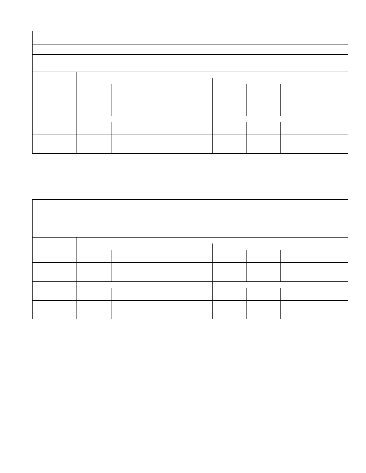
BLOWER DATA
G60UHV−36A−070 BLOWER PERFORMANCE
0 through 0.80 in. w.g. (0 Through 200 Pa) External Static Pressure Range
Blower Control Factory Settings ADJUST − NORM
HEAT − 2
COOL − 4
ADJUST"
Switch
Positions
Speed Switch Positions
2nd Stage HEAT" Speed 2nd Stage COOL" Speed
1 2 3 4 1 2 3 4
cfm L/s cfm L/s cfm L/s cfm L/s cfm L/s cfm L/s cfm L/s cfm L/s
+" (Plus) 910 430 1055 495 1305 615 1350 635 1045 495 1230 580 1315 620 1420 670
NORM (Normal) 830 390 940 445 1165 550 1215 575 945 445 1100 520 1190 560 1300 615
" (Minus) 745 350 845 400 1030 485 1070 505 850 400 975 460 1035 485 1130 535
ADJUST"
Switch
Positions
1st Stage HEAT" Speed 1st Stage COOL" Speed
1 2 3 4 1 2 3 4
cfm L/s cfm L/s cfm L/s cfm L/s cfm L/s cfm L/s cfm L/s cfm L/s
+" (Plus) 840 395 965 455 1195 565 1235 585 730 344 800 377 860 405 994 469
NORM (Normal) 765 360 865 410 1055 495 1105 520 680 320 745 351 780 368 850 401
" (Minus) 700 330 785 370 955 450 985 465 620 292 685 323 725 342 760 358
NOTES − The effect of static pressure and filter resistance is included in air volumes shown.
1st stage HEAT is approximately 91% of the same 2nd stage
HEAT speed position.
1st stage COOL (two speed air conditioning units only) is approximately 70% (65% for units built prior to 09−2002) of the same 2nd stage COOL speed position.
Continuous Fan Only speed is approximately 38% of the same 2nd stage COOL speed position − minimum 500 cfm (235 L/s).
Lennox Harmony II zone control applications − Minimum blower heating speed is approximately 75% of the 1st stage HEAT speed position.
Lennox Harmony II zone control applications − Minimum blower cooling speed is approximately 45% of the 2nd stage COOL speed position.
G60UHV−36B−090 BLOWER PERFORMANCE
0 through 0.80 in. w.g. (0 Through 200 Pa) External Static Pressure Range
Blower Control Factory Settings ADJUST − NORM
HEAT − 2
COOL − 4
ADJUST"
Switch
Positions
Speed Switch Positions
2nd Stage HEAT" Speed 2nd Stage COOL" Speed
1 2 3 4 1 2 3 4
cfm L/s cfm L/s cfm L/s cfm L/s cfm L/s cfm L/s cfm L/s cfm L/s
+" (Plus) N/A N/A 1035 490 1280 605 1335 630 1010 475 1175 555 1275 600 1400 660
NORM (Normal) N/A N/A 930 440 1150 540 1190 560 935 440 1055 495 1130 535 1250 590
" (Minus) N/A N/A 830 390 1020 480 1050 495 830 390 940 445 1005 475 1090 515
ADJUST"
Switch
Positions
1st Stage HEAT" Speed 1st Stage COOL" Speed
1 2 3 4 1 2 3 4
cfm L/s cfm L/s cfm L/s cfm L/s cfm L/s cfm L/s cfm L/s cfm L/s
+" (Plus) N/A N/A 935 440 1150 540 1195 565 740 349 800 377 850 401 910 429
NORM (Normal) N/A N/A 840 395 1035 490 1070 505 675 318 740 349 780 368 845 398
" (Minus) N/A N/A 755 355 930 440 965 455 615 290 690 325 715 337 750 353
NOTES − The effect of static pressure and filter resistance is included in air volumes shown.
1st stage HEAT is approximately 91% of the same 2nd stage HEAT speed position.
1st stage COOL (two speed air conditioning units only) is approximately 70% (65% for units built prior to 09−2002) of the same 2nd stage COOL speed position.
Continuous Fan Only speed is approximately 38% of the same 2nd stage COOL speed position − minimum 500 cfm (235 L/s).
Lennox Harmony II zone control applications − Minimum blower heating speed is approximately 75% of the 1st stage HEAT speed position.
Lennox Harmony II zone control applications − Minimum blower cooling speed is approximately 45% of the 2nd stage COOL speed position.
N/A − 1st stage HEAT, speed position 1, cannot be used with this model.
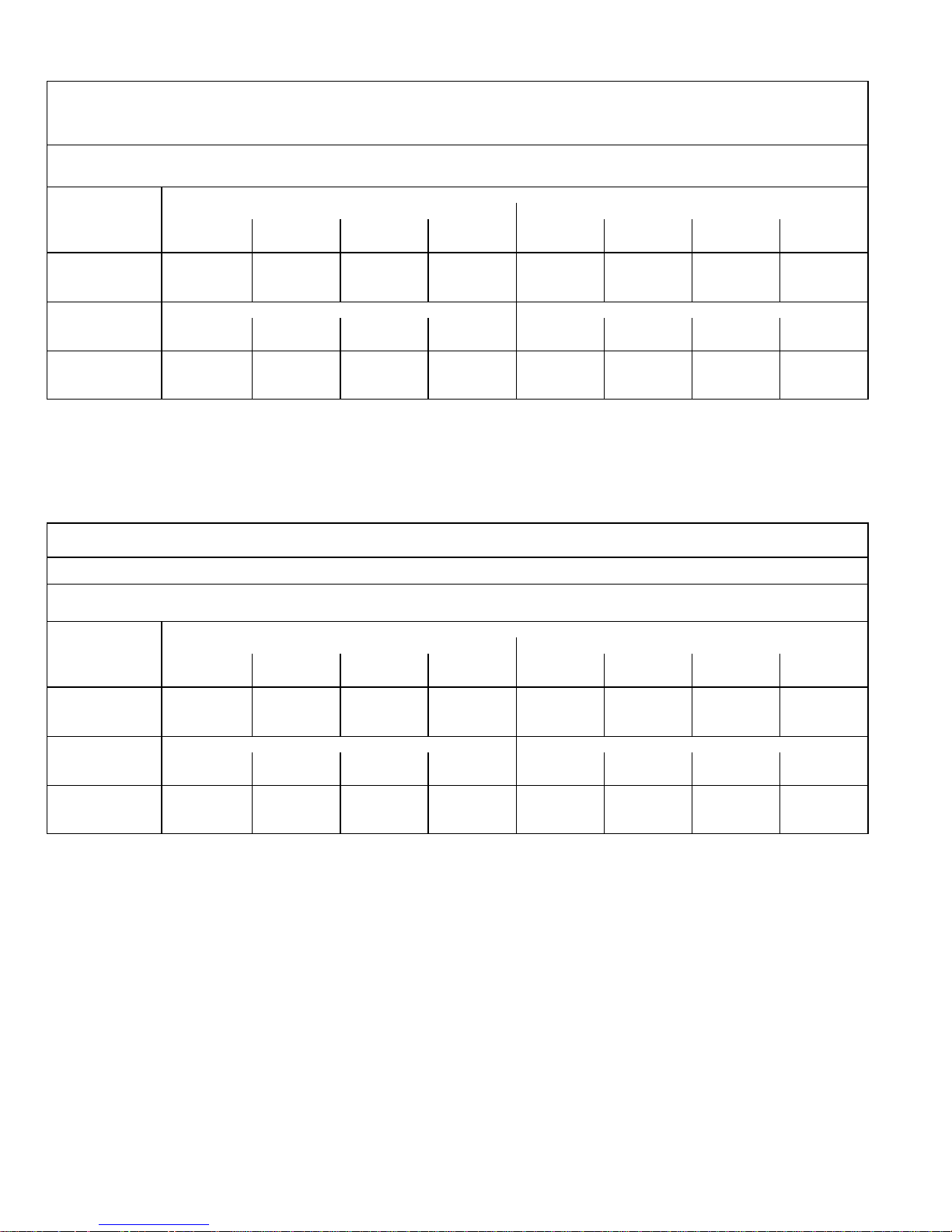
G60UHV−60C−090 BLOWER PERFORMANCE
0 through 0.80 in. w.g. (0 Through 200 Pa) External Static Pressure Range
Bottom Return Air, Side Return Air with Optional RAB Return Air Base, Return Air from Both Sides or
Return Air from Bottom and One Side.
Blower Control Factory Settings ADJUST − NORM
HEAT − 2
COOL − 4
ADJUST"
Switch
Positions
Speed Switch Positions
2nd Stage HEAT" Speed 2nd Stage COOL" Speed
1 2 3 4 1 2 3 4
cfm L/s cfm L/s cfm L/s cfm L/s cfm L/s cfm L/s cfm L/s cfm L/s
+" (Plus) 1525 720 1715 810 1935 915 2125 1005 1630 770 1760 830 1960 925 2185 1030
NORM (Normal) 1385 655 1560 735 1760 830 1930 910 1480 700 1600 755 1785 840 1985 935
" (Minus) 1245 590 1400 660 1580 745 1740 820 1335 630 1440 680 1605 755 1785 845
ADJUST"
Switch
Positions
1st Stage HEAT" Speed 1st Stage COOL" Speed
1 2 3 4 1 2 3 4
cfm L/s cfm L/s cfm L/s cfm L/s cfm L/s cfm L/s cfm L/s cfm L/s
+" (Plus) 1395 660 1580 745 1780 840 1960 925 1120 528 1200 566 1370 646 1550 731
NORM (Normal) 1265 595 1440 680 1615 760 1780 840 1000 471 1100 519 1250 589 1375 648
" (Minus) 1140 540 1295 610 1465 690 1605 755 900 424 975 460 1120 528 1230 580
NOTES − The effect of static pressure and filter resistance is included in air volumes shown.
1st stage HEAT is approximately 91% of the same 2nd stage HEAT speed position.
1st stage COOL (two speed air conditioning units only) is approximately 70% (60% for units built prior to 09−2002) of the same 2nd stage COOL speed position.
Continuous Fan Only speed is approximately 38% of the same 2nd stage COOL speed position.
Lennox Harmony II zone control applications − Minimum blower heating speed is approximately 75% of the 1st stage HEAT speed position.
Lennox Harmony II zone control applications − Minimum blower cooling speed is approximately 42% of the 2nd stage COOL speed position.
Page 5
Page 5
BLOWER DATA
G60UHV−60C−090 BLOWER PERFORMANCE
0 through 0.80 in. w.g. (0 Through 200 Pa) External Static Pressure Range
Single Side Return Air − Air volumes in bold require field fabricated transition to accommodate 20 x 25 x 1 in. (508 x 635 x 25 mm) cleanable air filter in order to maintain proper air velocity across the filter.
Blower Control Factory Settings ADJUST − NORM
HEAT − 2
COOL − 4
ADJUST"
Switch
Positions
Speed Switch Positions
2nd Stage HEAT" Speed 2nd Stage COOL" Speed
1 2 3 4 1 2 3 4
cfm L/s cfm L/s cfm L/s cfm L/s cfm L/s cfm L/s cfm L/s cfm L/s
+" (Plus) 1475 695 1665 785 1870 880 2050 965 1580 745 1700 800 1920 905 2110 995
NORM (Normal) 1340 630 1515 715 1700 800 1865 880 1435 675 1545 730 1745 825 1920 905
" (Minus) 1205 570 1365 645 1530 720 1680 790 1290 610 1390 655 1570 740 1730 815
ADJUST"
Switch
Positions
1st Stage HEAT" Speed 1st Stage COOL" Speed
1 2 3 4 1 2 3 4
cfm L/s cfm L/s cfm L/s cfm L/s cfm L/s cfm L/s cfm L/s cfm L/s
+" (Plus) 1355 640 1535 725 1710 805 1890 890 1070 504 1160 547 1325 625 1490 703
NORM (Normal) 1230 580 1395 660 1555 735 1720 810 955 450 1060 500 1210 570 1325 625
" (Minus) 1105 520 1255 590 1400 660 1550 730 860 405 935 441 1085 512 1185 559
NOTES − The effect of static pressure and filter resistance is included in air volumes shown.
1st stage HEAT is approximately 91% of the same 2nd stage HEAT speed position.
1st stage COOL (two speed air conditioning units only) is approximately 70% (60% for units built prior to 09−2002) of the same 2nd stage COOL speed position.
Continuous Fan Only speed is approximately 38% of the same 2nd stage COOL speed position.
Lennox Harmony II zone control applications − Minimum blower heating speed is approximately 75% of the 1st stage HEAT speed position.
Lennox Harmony II zone control applications − Minimum blower cooling speed is approximately 42% of the 2nd stage COOL speed position.
G60UHV−60C−110 BLOWER PERFORMANCE
0 through 0.80 in. w.g. (0 Through 200 Pa) External Static Pressure Range
Bottom Return Air, Side Return Air with Optional RAB Return Air Base, Return Air from Both Sides or
Return Air from Bottom and One Side.
Blower Control Factory Settings ADJUST − NORM
HEAT − 2
COOL − 4
ADJUST"
Switch
Positions
Speed Switch Positions
2nd Stage HEAT" Speed 2nd Stage COOL" Speed
1 2 3 4 1 2 3 4
cfm L/s cfm L/s cfm L/s cfm L/s cfm L/s cfm L/s cfm L/s cfm L/s
+" (Plus) 1485 700 1695 800 1910 900 2130 1005 1630 770 1750 825 1980 935 2185 1030
NORM (Normal) 1350 635 1540 730 1735 820 1935 915 1480 700 1590 750 1800 850 1985 940
" (Minus) 1215 575 1390 655 1560 735 1740 820 1335 630 1435 675 1620 765 1790 845
ADJUST"
Switch
Positions
1st Stage HEAT" Speed 1st Stage COOL" Speed
1 2 3 4 1 2 3 4
cfm L/s cfm L/s cfm L/s cfm L/s cfm L/s cfm L/s cfm L/s cfm L/s
+" (Plus) 1365 645 1550 730 1735 820 1925 910 1080 509 1075 507 1315 620 1445 681
NORM (Normal) 1240 585 1410 665 1575 745 1750 825 990 467 1050 495 1195 563 1315 620
" (Minus) 1115 525 1270 600 1420 670 1575 745 890 419 940 443 1075 507 1195 563
NOTES − The effect of static pressure and filter resistance is included in air volumes shown.
1st stage HEAT is approximately 91% of the same 2nd stage HEAT speed position.
1st stage COOL (two speed air conditioning units only) is approximately 70% (60% for units built prior to 09−2002) of the same 2nd stage COOL speed position.
Continuous Fan Only speed is approximately 38% of the same 2nd stage COOL speed position.
Lennox Harmony II zone control applications − Minimum blower heating speed is approximately 75% of the 1st stage HEAT speed position.
Lennox Harmony II zone control applications − Minimum blower cooling speed is approximately 42% of the 2nd stage COOL speed position.
Page 6
Page 6
BLOWER DATA
G60UHV−60C−110 BLOWER PERFORMANCE
0 through 0.80 in. w.g. (0 Through 200 Pa) External Static Pressure Range
Single Side Return Air − Air volumes in bold require field fabricated transition to accommodate 20 x 25 x 1 in. (508 x 635 x 25 mm) cleanable air filter in order to maintain proper air velocity across the filter.
Blower Control Factory Settings ADJUST − NORM
HEAT − 2
COOL − 4
ADJUST"
Switch
Positions
Speed Switch Positions
2nd Stage HEAT" Speed 2nd Stage COOL" Speed
1 2 3 4 1 2 3 4
cfm L/s cfm L/s cfm L/s cfm L/s cfm L/s cfm L/s cfm L/s cfm L/s
+" (Plus) 1430 675 1615 765 1835 865 2040 965 1530 720 1660 785 1875 885 2100 990
NORM (Normal) 1300 615 1470 695 1665 785 1855 875 1390 655 1510 715 1705 805 1910 900
" (Minus) 1170 550 1325 625 1500 710 1670 790 1250 590 1360 640 1535 725 1720 810
ADJUST"
Switch
Positions
1st Stage HEAT" Speed 1st Stage COOL" Speed
1 2 3 4 1 2 3 4
cfm L/s cfm L/s cfm L/s cfm L/s cfm L/s cfm L/s cfm L/s cfm L/s
+" (Plus) 1305 615 1480 700 1680 790 1865 880 965 455 1060 500 1205 568 1345 634
NORM (Normal) 1185 560 1345 635 1525 720 1695 800 885 417 965 455 995 469 1225 578
" (Minus) 1065 505 1210 570 1375 650 1525 720 795 375 875 412 985 464 111 5 526
NOTES − The effect of static pressure and filter resistance is included in air volumes shown.
1st stage HEAT is approximately 91% of the same 2nd stage HEAT speed position.
1st stage COOL (two speed air conditioning units only) is approximately 70% (60% for units built prior to 09−2002) of the same 2nd stage COOL speed position.
Continuous Fan Only speed is approximately 38% of the same 2nd stage COOL speed position.
Lennox Harmony II zone control applications − Minimum blower heating speed is approximately 75% of the 1st stage HEAT speed position.
Lennox Harmony II zone control applications − Minimum blower cooling speed is approximately 42% of the 2nd stage COOL speed position.
G60UHV−60D−135 BLOWER PERFORMANCE
0 through 0.80 in. w.g. (0 Through 200 Pa) External Static Pressure Range
Bottom Return Air, Side Return Air with Optional RAB Return Air Base, Return Air from Both Sides or
Return Air from Bottom and One Side.
Blower Control Factory Settings ADJUST − NORM
HEAT − 2
COOL − 4
ADJUST"
Switch
Positions
Speed Switch Positions
2nd Stage HEAT" Speed 2nd Stage COOL" Speed
1 2 3 4 1 2 3 4
cfm L/s cfm L/s cfm L/s cfm L/s cfm L/s cfm L/s cfm L/s cfm L/s
+" (Plus) 1520 715 1725 815 1940 915 2130 1005 1630 770 1760 830 1985 935 2200 1040
NORM (Normal) 1385 655 1570 740 1765 835 1940 915 1480 700 1600 755 1805 850 2000 945
" (Minus) N/A N/A 1410 665 1590 750 1745 825 1335 630 1440 680 1625 765 1800 850
ADJUST"
Switch
Positions
1st Stage HEAT" Speed 1st Stage COOL" Speed
1 2 3 4 1 2 3 4
cfm L/s cfm L/s cfm L/s cfm L/s cfm L/s cfm L/s cfm L/s cfm L/s
+" (Plus) 1395 660 1580 745 1760 830 1960 925 1090 514 1170 552 1315 620 1450 684
NORM (Normal) 1265 595 1435 675 1600 755 1785 840 995 469 1060 500 1200 566 1320 622
" (Minus) N/A N/A 1295 610 1440 680 1605 755 895 422 950 448 1080 509 1200 566
NOTES − The effect of static pressure and filter resistance is included in air volumes shown.
1st stage HEAT is approximately 91% of the same 2nd stage HEAT speed position.
1st stage COOL (two speed air conditioning units only) is approximately 70% (65% for units built prior to 09−2009) of the same 2nd stage COOL speed position.
Continuous Fan Only speed is approximately 38% of the same 2nd stage COOL speed position.
Lennox Harmony II zone control applications − Minimum blower heating speed is approximately 75% of the 1st stage HEAT speed position.
Lennox Harmony II zone control applications − Minimum blower cooling speed is approximately 45% of the 2nd stage COOL speed position.
N/A − 1st stage HEAT, speed position 1 with " (Minus) Adjust" setting, cannot be used with this model.
Page 7
Page 7
BLOWER DATA
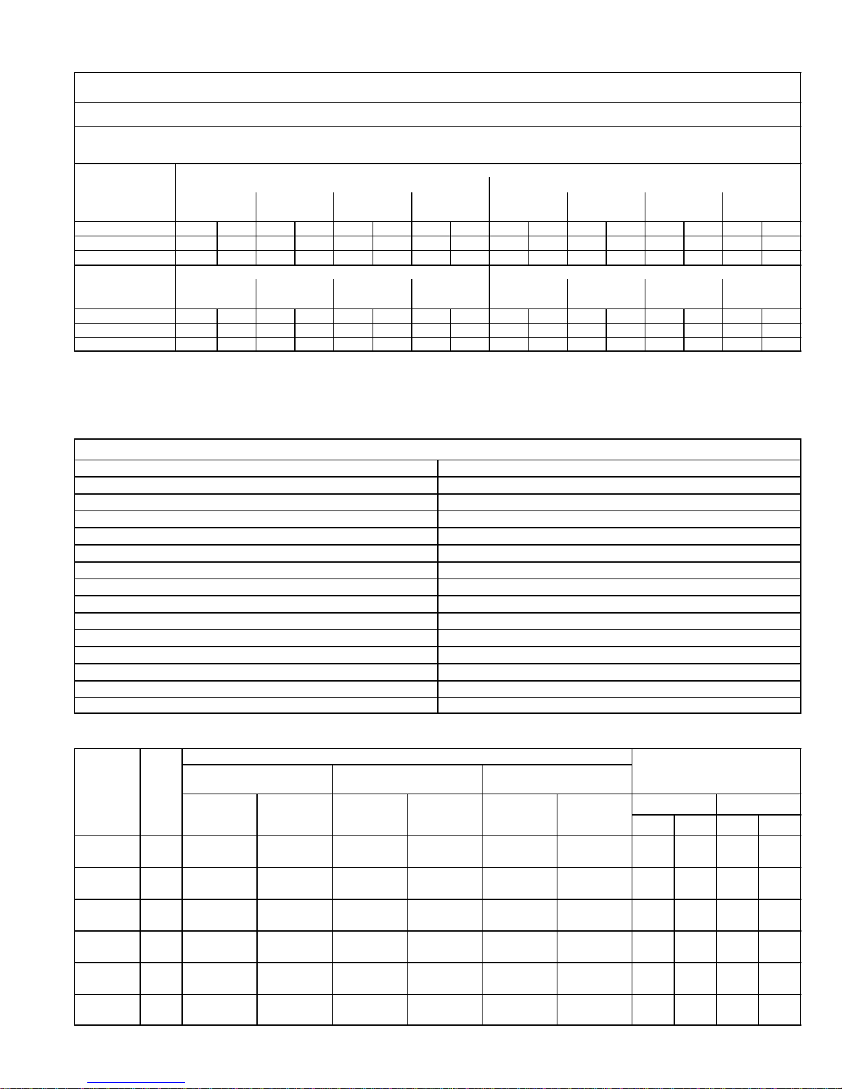
G60UHV−60D−135 BLOWER PERFORMANCE
0 through 0.80 in. w.g. (0 Through 200 Pa) External Static Pressure Range
Single Side Return Air − Air volumes in bold require field fabricated transition to accommodate 20 x 25 x 1 in. (508 x 635 x 25 mm) cleanable air filter in order to maintain proper air velocity across the filter.
Blower Control Factory Settings ADJUST − NORM
HEAT − 2
COOL − 4
ADJUST"
Switch
Positions
Speed Switch Positions
2nd Stage HEAT" Speed 2nd Stage COOL" Speed
1 2 3 4 1 2 3 4
cfm L/s cfm L/s cfm L/s cfm L/s cfm L/s cfm L/s cfm L/s cfm L/s
+" (Plus) 1415 665 1625 765 1820 860 2015 950 1525 720 1650 780 1875 885 2095 990
NORM (Normal) 1285 605 1475 695 1655 780 1830 865 1385 655 1500 710 1705 805 1905 900
" (Minus) N/A N/A 1330 625 1490 705 1645 775 1245 590 1350 635 1535 725 1715 810
ADJUST"
Switch
Positions
1st Stage HEAT" Speed 1st Stage COOL" Speed
1 2 3 4 1 2 3 4
cfm L/s cfm L/s cfm L/s cfm L/s cfm L/s cfm L/s cfm L/s cfm L/s
+" (Plus) 1300 615 1480 700 1660 785 1850 875 965 455 1070 504 1215 573 1345 634
NORM (Normal) 1180 555 1345 635 1510 715 1680 795 885 417 975 460 1105 521 1225 578
" (Minus) N/A N/A 1210 570 1360 640 1510 715 795 375 870 410 995 469 111 5 526
NOTES − The effect of static pressure and filter resistance is included in air volumes shown.
1st stage HEAT is approximately 91% of the same 2nd stage HEAT speed position.
1st stage COOL (two speed air conditioning units only) is approximately 70% (65% for units built prior to 09−2002) of the same 2nd stage COOL speed position.
Continuous Fan Only speed is approximately 38% of the same 2nd stage COOL speed position.
Lennox Harmony II zone control applications − Minimum blower heating speed is approximately 75% of the 1st stage HEAT speed position.
Lennox Harmony II zone control applications − Minimum blower cooling speed is approximately 45% of the 2nd stage COOL speed position.
N/A − 1st stage HEAT, speed position 1 with " (Minus) Adjust" setting, cannot be used with this model.
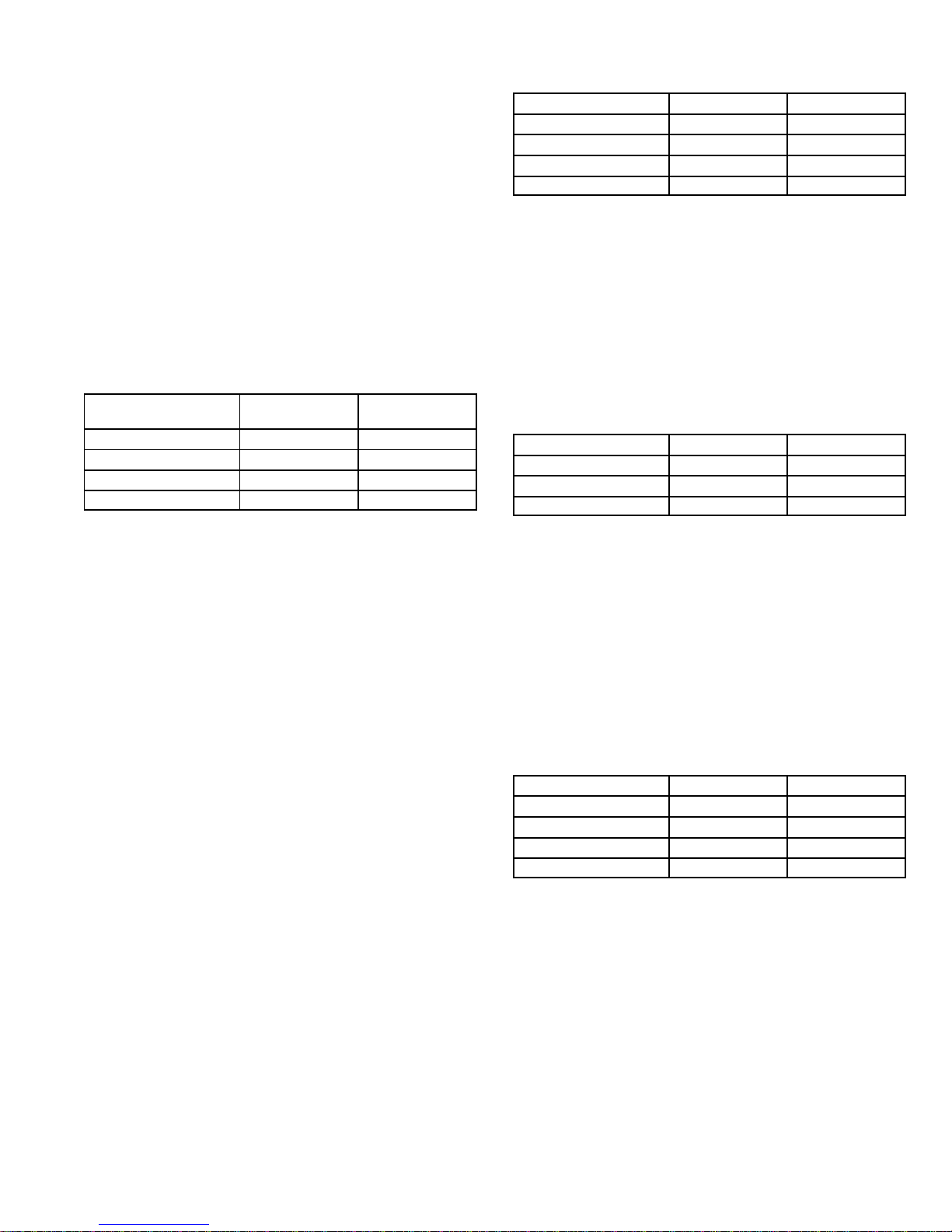
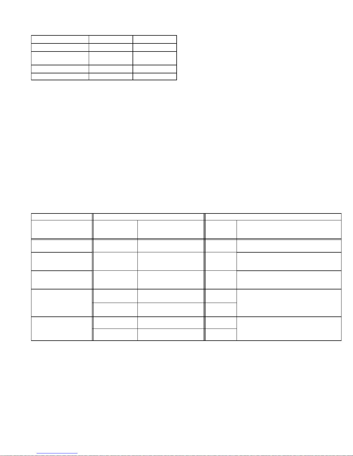
FILTER AIR RESISTANCE
cfm L/s in. w.g. Pa
0 0 0.00 0
200 95 0.01 0
400 190 0.03 5
600 285 0.04 10
800 380 0.06 15
1000 470 0.09 20
1200 565 0.12 30
1400 660 0.15 35
1600 755 0.19 45
1800 850 0.23 55
2000 945 0.27 65
2200 1040 0.33 80
2400 1130 0.38 95
2600 1225 0.44 110
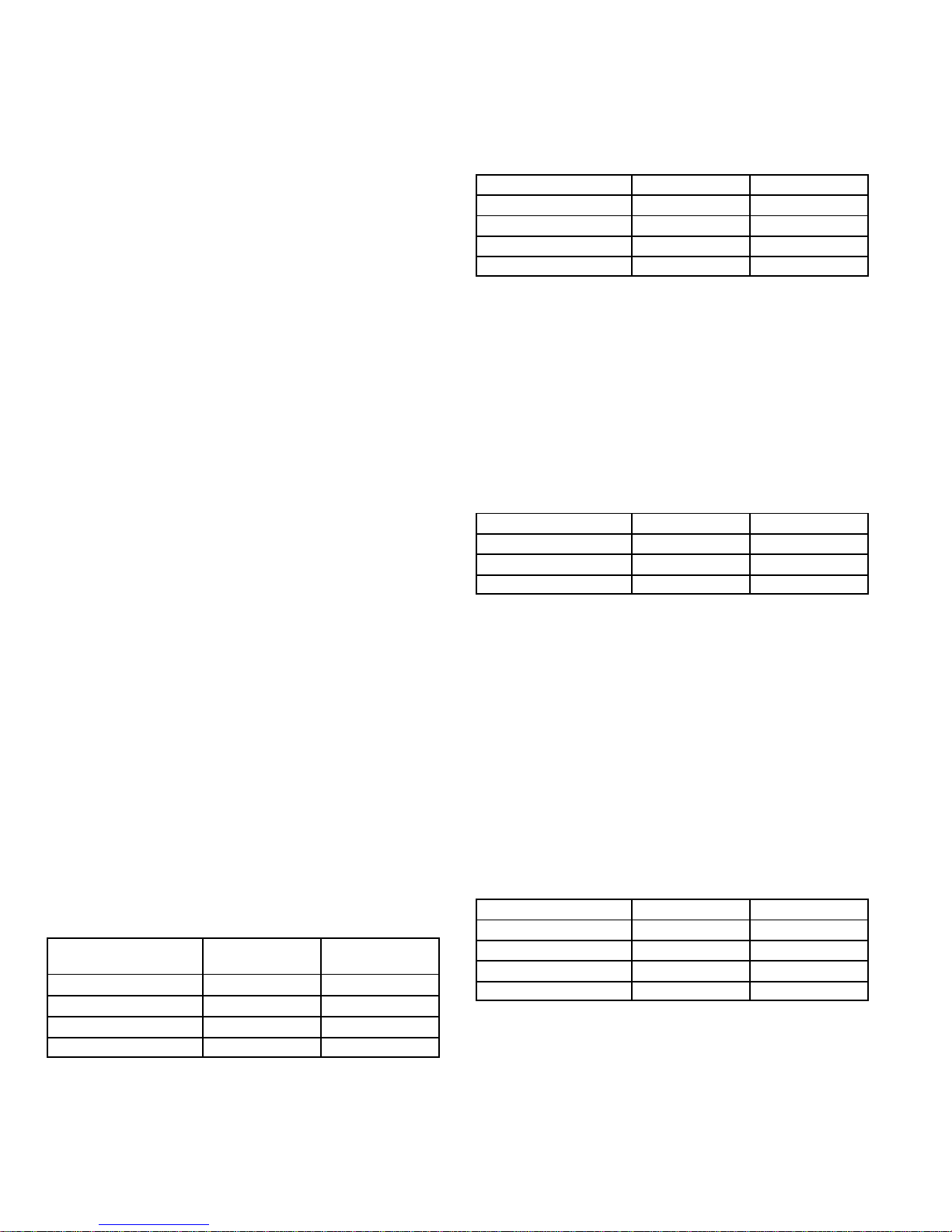
HIGH ALTITUDE
Model
Input
Size
Gas
Altitude
Manifold Pressure
at all altitudes
0 − 4500 ft.
(0 − 1372 m)
4,501 − 7500 ft.
(1373 − 2286 m)
7501−10,000 ft.
(2286 − 3048 m)
Required
Conversion
Kit
Pressure
Switch
Required
Conversion
Kit
Pressure
Switch
Required
Conversion
Kit
Pressure
Switch
Low Fire High Fire
in. w.g. kPa in. w.g. kPa
070−1 to −6
Nat. N/A No Change N/A No Change 59M16 18M64 1.7 0.42 3.5 0.87
LPG 59M13 No Change 59M13 No Change 59M14 18M64 4.9 1.22 10.0 2.5
090−1 to −6
Nat. N/A No Change N/A 18M61 59M16 18M64 1.7 0.42 3.5 0.87
LPG 59M13 No Change 59M13 18M61 59M14 18M64 4.9 1.22 10.0 2.5
110/135−1 to
−6
Nat. N/A No Change N/A 18M63 59M16 18M61 1.7 0.42 3.5 0.87
LPG 59M13 No Change 59M13 18M63 59M14 18M61 4.9 1.22 10.0 2.5
070−7 and
later
Nat. N/A No Change N/A No Change 59M17 18M64 1.7 0.42 3.5 0.87
LPG 59M13 No Change 59M13 No Change 59M14 18M64 4.9 1.22 10.0 2.5
090−7 and
later
Nat. N/A No Change N/A 18M61 59M17 18M64 1.7 0.42 3.5 0.87
LPG 59M13 No Change 59M13 18M61 59M14 18M64 4.9 1.22 10.0 2.5
110/135−7
and later
Nat. N/A No Change N/A 18M63 59M17 18M61 1.7 0.42 3.5 0.87
LPG 59M13 No Change 59M13 18M63 59M14 18M61 4.9 1.22 10.0 2.5
Pressure switch is factory set. No adjustment necessary. All models use the factory installed pressure switch from 0−4500 feet (0−1370 m).
Page 8
Page 8
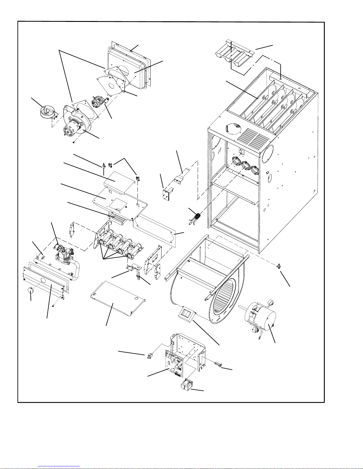
FIGURE 1
Flue
Transition
Combustion Air Inducer
Combustion Air
Orifice
Combustion Air
Prove Switch Assembly
(two switches)
Flue
Collector
Box
Heat Exchanger
Flame Sensor
Gas Valve
Burners
Ignitor
NO
x
Insert
Primary
Limit
Door Interlock Switch
SureLight Two−Stage,
Variable Speed
Integrated Control Board
Control Transformer
Circuit Breaker
Gasket
Flue Box Gasket
Gas
Orifices
Ignitor
Bracket
Burner Box Bottom
Limit Shield
Secondary Limit(s)
(NOx Units Only)
Air Deflector
G60UH−60C−110
Units Only
Variable Speed
Blower Motor
Flame Rollout Switches
Air Intake
Cover
Air Baffle
Gasket
Burner
Box Cover
Power Choke
(1 hp Only)
Sight
Glass
Burner
Box Top
G60UHV(X) PARTS ARRANGEMENT
Page 9
Page 9
I−UNIT COMPONENTS
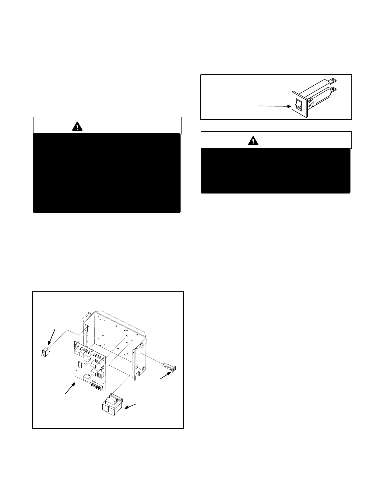
G60UHV(X) unit components are shown in figure 1. The
gas valve, combustion air inducer and burners can be accessed by removing the burner access panel. Electrical
components are in the control box (figure 2) found in the
blower section.
G60UHV(X) units are factory equipped with a bottom return
air panel in place. The panel is designed to be field removed
as required for bottom air return. Markings are provided for
side return air and may be cut out in the field.
CAUTION
Electrostatic discharge can affect electronic
components. Take precautions during furnace
installation and service to protect the furnace’s
electronic controls. Precautions will help to
avoid control exposure to electrostatic discharge by putting the furnace, the control and
the technician at the same electrostatic potential. Neutralize electrostatic charge by touching
hand and all tools on an unpainted unit surface,
such as the gas valve or blower deck, before performing any service procedure.
ELECTROSTATIC DISCHARGE (ESD)
Precautions and Procedures
1. Control Transformer (T1)
A transformer located in the control box provides power to
the low voltage section of the unit. Transformers on all
models are rated 40VA with a 120V primary and a 24V secondary.
2. Door Interlock Switch (S51)
A door interlock switch rated 14A at 125VAC is wired in series with line voltage. When the blower door is removed the
unit will shut down.
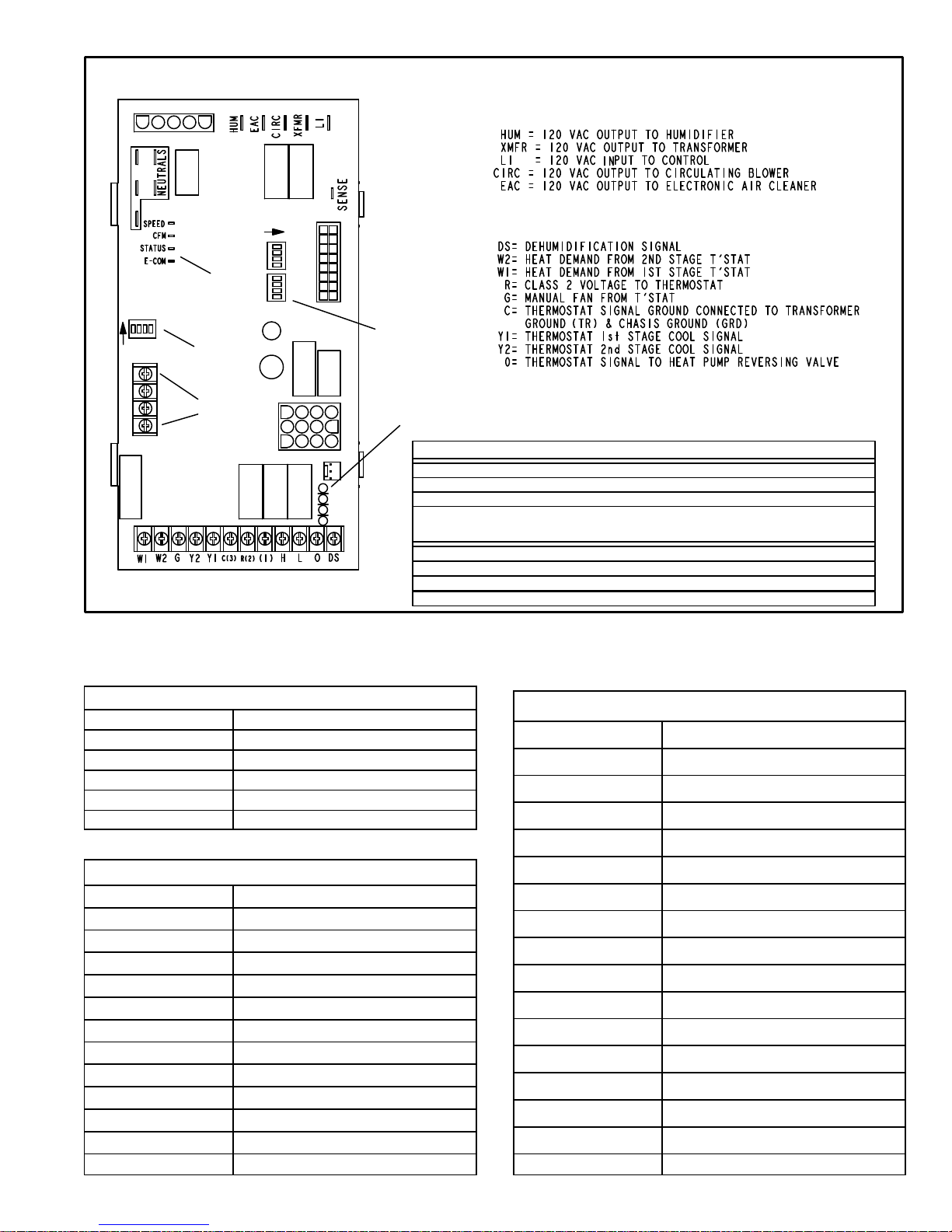
FIGURE 2
CONTROL BOX G60UHV(X)
SureLight
CONTROL
BOARD
TRANSFORMER
CIRCUIT BREAKER
DOOR INTERLOCK
SWITCH
3. Circuit Breaker (CB8)
A 24V circuit breaker is also located in the control box.
The switch provides overcurrent protection to the transformer (T1). The breaker is rated 3A at 32V. If the current
exceeds this limit the breaker will trip and all unit operation will shutdown. The breaker can be manually reset
by pressing the button on the face. See figure 3.
FIGURE 3
CIRCUIT BREAKER CB8
PRESS TO RESET
WARNING
Shock hazard.
Disconnect power before servicing. Integrated
Control Board is not field repairable. If control is
inoperable, simply replace entire control.
Can cause injury or death. Unsafe operation will
result if repair is attempted.
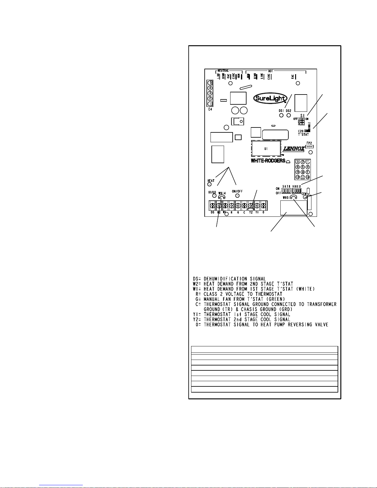
4. Integrated Control Board(A92)
Boards 18M99 and 49M59
All G60UHV units are equipped with the Lennox two−
stage, variable speed integrated SureLight control board.
The system consists of a ignition / blower control board
(figure 4 with control terminal designations in tables 1
through 4) and ignitor (figure 12). The board and ignitor
work in combination to ensure furnace ignition and ignitor
durability. The SureLight integrated board controls all major furnace operations. The board features two LED lights,
DS1 and DS2 for troubleshooting and four LED lights
(DS3, DS6, DS7 and DS8) to show furnace status. The
board also has two accessory terminals rated at (1) one
amp each. See table 5 for status code and table 6 for troubleshooting diagnostic codes.
Electronic Ignition
At the beginning of the heat cycle the SureLight control
monitors the first stage and second stage combustion air
inducer prove switch. The control will not begin the heating
cycle if the first stage prove switch is closed (by−passed).
Likewise the control will not begin the second stage heating
cycle if the second stage prove switch is closed, and will remain in first stage heat. However, if the second stage prove
switch closes during the first stage heat pre−purge, the control will allow second stage heat. Once the first stage prove
switch is determined to be open, the combustion air inducer is energized on low (first stage) heat speed. When the
differential in the prove switch is great enough, the prove
switch closes and a 15−second pre−purge begins. If the
switch is not proven within 2−1/2 minutes, the control goes
into Watchguard−Pressure Switch mode for a 5−minute re−
set period.
Page 10
Page 10
After the 15−second pre−purge period, the SureLight ignitor
warms up for 20 seconds after which the gas valve opens
for a 4−second trial for ignition. The ignitor energizes during
the trial until flame is sensed. If ignition is not proved during
the 4−second period, the control will try four more times with
an inter purge and warm−up time between trials of 35 seconds. After a total of five trials for ignition (including the initial trial), the control goes into Watchguard−Flame Failure
mode. After a 60−minute reset period, the control will begin
the ignition sequence again.
The SureLight control board has an added feature that prolongs the life of the ignitor. After a successful ignition, the
SureLight control utilizes less power to energize the ignitor
on successive calls for heat. The control continues to ramp
down the voltage to the ignitor until it finds the lowest
amount of power that will provide a successful ignition. This
amount of power is used for 255 cycles. On the 256th call
for heat, the control will again ramp down until the lowest
power is determined and the cycle begins again.
Two Stage Operation / Thermostat Selection Jumper
The control can be utilized in two modes: SINGLE−STAGE
thermostat or TWO−STAGE thermostat. The thermostat
selection jumper E20, located just below dip switches 1
through 3 (figure 4), must be positioned for the particular
application. The jumper is factory set on TWO" for use
with a two−stage thermostat with two stage heat. Re−position jumper to SINGLE" for use with a single stage thermostat with two stage heat.
While in the single−stage thermostat mode (single jumper
setting), the burners will always fire on first−stage heat. The
combustion air inducer will operate on low speed and indoor blower will operate on low heat speed. After a 10 minute recognition period, the unit will switch to second stage
heat. While in the two−stage thermostat mode (two jumper
setting) the burners will fire on first−stage heat. The combustion air inducer will operate on low speed and indoor
blower will operate on low heat speed. The unit will switch
to second−stage heat on call from the indoor thermostat. If
there is a simultaneous call for first and second stage heat,
the unit will fire an first stage heat and switch to second
stage heat after 30 seconds of operation. See Sequence of
Operation flow charts in the back of this manual for more
detail.
TW0−STAGE, VARIABLE SPEED INTEGRATED
CONTROL BOARD
FIGURE 4
DIP
SWITCHES
1 − 3
DIP
SWITCHES
5 − 12
DIAGNOSTIC
LEDs
ON−BOARD
JUMPER W951
(cut when heat pump
is used with FM21)
ON−BOARD
JUMPER W914
(cut when SignatureStat,
CCB1 or Harmony II are used)
LEDs
LED
FACTORY−
INSTALLED
JUMPER
THERMOSTAT CONNECTIONS (TB1)
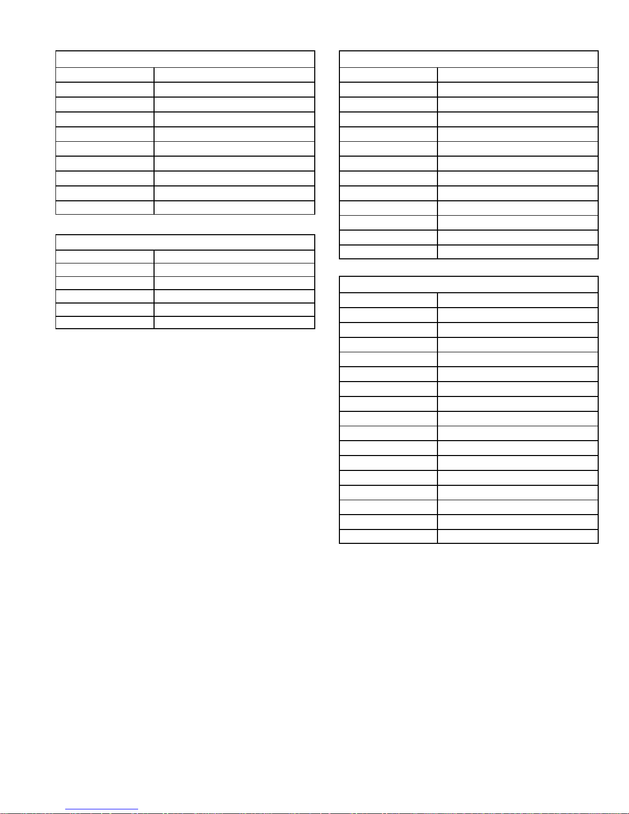
DIP SWITCH FUNCTIONS
DIP SWITCH(ES) FUNCTION
1 and 2 Blower Off Delay
3 Second Stage ON Delay (Single−stage t’stat)
4 Not used
5 and 6 Cooling Mode Blower Speed
7 and 8 Blower Speed Adjustment
9 and 10 Cooling Mode Blower Ramping Profile
11 and 12 Heating Mode Blower Speed
E20
JUMPER
16 PIN BLOWER
CONTROL TERMINALS
DS8
DS7
DS3
DS6
Page 11
Page 11
TABLE 1
Two Stage Ignition / Blower Control Terminals
LINE Line 120VAC Neutral
XFMR Transformer 120VAC Neutral
EAC Electronic Air Cleaner 120VAC Neutral
CIRC Indoor Blower 120VAC Neutral
HUM Humidifier 120VAC Neutral
HUM Humidifier 120VAC Hot
XMFR Transformer 120VAC Hot
LINE Line 120VAC Hot
CIRC Indoor Blower 120VAC Hot
EAC Electronic Air Cleaner 120VAC Hot
TABLE 2
SureLight Board 5 Pin Terminal Designation
PIN # Function
1 Ignitor
2 Combustion Air Inducer High Speed
3 Combustion Air Inducer Low Speed
4 Combustion Air Inducer Neutral
5 Ignitor Neutral
TABLE 3
SureLight Board 12Pin Terminal Designation
PIN # Function
1 Gas Valve High Fire
2 Second Stage Pressure Switch
3 Not Used
4 Ground
5 24V Hot
6 Primary Limit In
7 Gas Valve Low Stage
8 Gas Valve Common
9 24V Neutral
10 Ground
11 Primary Limit Out
12 1st Stage Pressure Switch
TABLE 4
SureLight Board 16 Pin Blower Control Terminals
PIN # Function
1 Ground
2 Low Heat Speed
3 Ground
4 DELAY" Dip Switch Selection
5 COOL" Dip Switch Selection
6 Y1" Signal
7 ADJUST" Dip Switch Selection
8 Ground
9 0" From Thermostat
10 DS" Output Signal
11 HEAT" Dip Switch Selection
12 24 VAC
13 HIGH HEAT Speed
14 Y2" Signal
15 G"
16 CFM LED
Page 12
Page 12
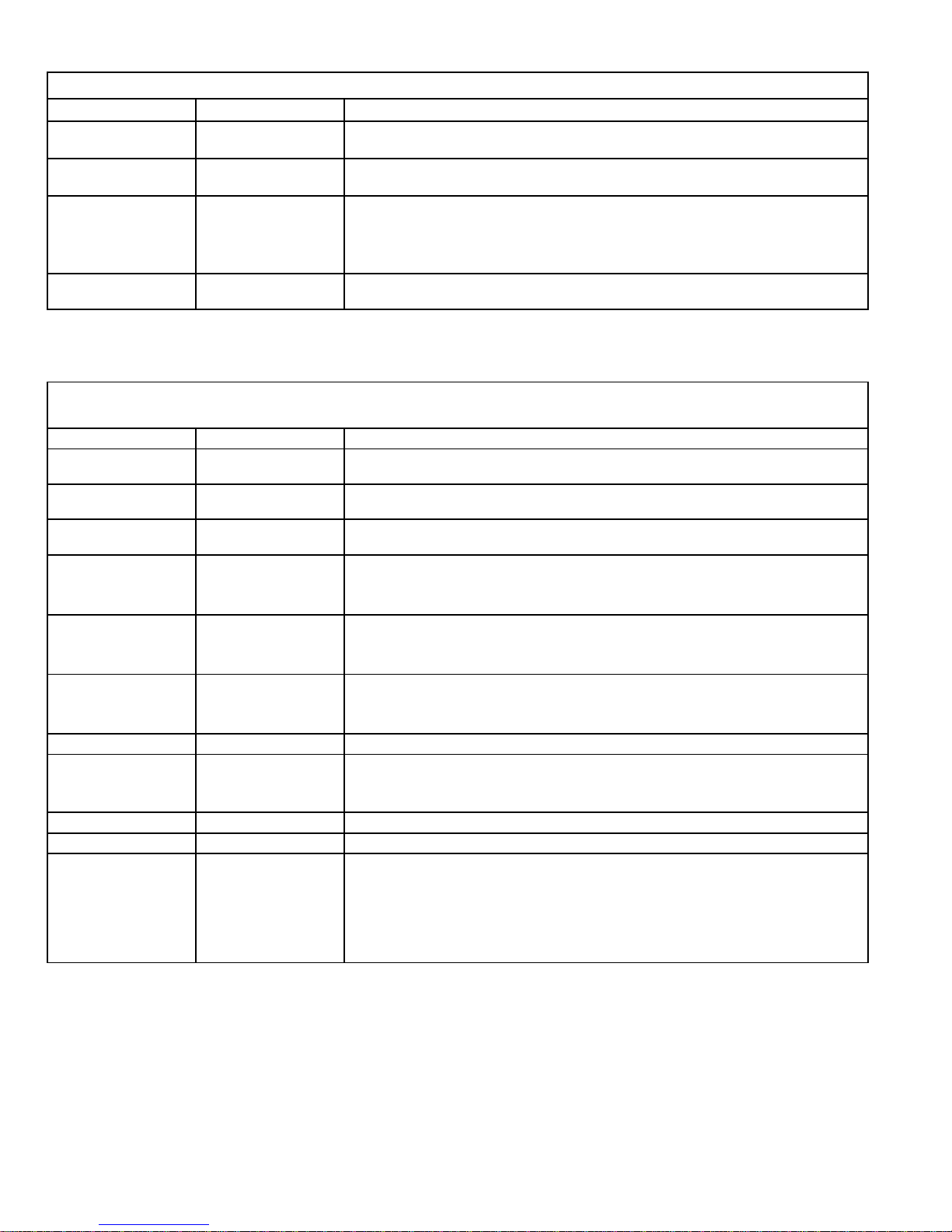
TABLE 5
STATUS CODES
STATUS LED COLOR FUNCTION
DS3
ON / OFF ’
GREEN
DS3−ON indicates that the motor has a demand to operate. (This LED must be on in all
modes).
DS6
CFM"
GREEN
DS6−blinking indicates the airflow (CFM) demand in the motor. The air flow is determine by
counting blinks between two (2) second pauses. One blink equals roughly 100 CFM.
DS7
HI / LO"
YELLOW
DS7−ON indicaties the DS to R" jumper has not been cut. When the jumper is cut the system
will be operating with LENNOX HARMONY II (See Harmony Installation Instructions) or
with the CCB1 Efficiency Plus control.
CCB1: When ON, a 24 VAC is being applied and when OFF, it has been removed. This on/off
operation varies the indoor blower’s performance so dehumidification can be enhanced.
DS8
HEAT"
YELLOW DS8−ON indicates the sytem is in HEAT mode.
TABLE 6
DIAGNOSTIC CODES
Diagnostic LEDs are labeled DS1 and DS2. See figure 4 for location of diagnostic LEDs.
DS1 DS2 DESCRIPTION
SIMULTANEOUS
SLOW FLASH
SIMULTANEOUS
SLOW FLASH
Power on − Normal operation.
Also signaled during cooling and continuous fan.
SIMULTANEOUS
FAST FLASH
SIMULTANEOUS
FAST FLASH
Normal operation − signaled when heating demand initiated at thermostat.
SLOW FLASH ON
Primary, secondary or rollout limit switch open. Limits must close within 3 minutes
or unit goes into 1 hour Watchguard.
OFF SLOW FLASH
Low prove switch open;
OR: Blocked inlet/exhaust vent;
OR: Low prove switch closed prior to activation of combustion air inducer.
OFF FAST FLASH
High prove switch open;
OR: Blocked inlet/exhaust vent;
OR: High prove switch closed prior to activation of combustion air inducer.
ALTERNATING
SLOW FLASH
ALTERNATING
SLOW FLASH
Watchguard −− burners failed to ignite; OR limit open more than 3 minutes;
OR lost flame sense 5 times in one heating cycle;
OR prove switch opened 5 times in one heating cycle.
SLOW FLASH OFF Flame sensed without gas valve energized.
ON
ON
OFF
ON
OFF
ON
Circuit board failure or control wired incorrectly. Check 24 and 115 volts to board.
FAST FLASH SLOW FLASH Main power polarity reversed. Switch line and neutral.
SLOW FLASH FAST FLASH Low flame signal. Measures below 0.23 microAmps. Replace flame sense rod.
ALTERNATING
FAST FLASH
ALTERNATING
FAST FLASH
The following conditions are sensed during the ignitor warm−up period only:
1) Improper main ground;
2) Broken ignitor; OR: Open ignitor circuit;
3) Line voltage below 75 volts.
(If voltage lower than 75 volts prior to ignitor warm-up, control will signal waiting on
call from thermostat, and will not respond.
NOTE − Slow flash rate equals 1 Hz (one flash per second). Fast flash rate equals 3 Hz (three flashes per second).
Low flame sense current = 0.17 − .22 microAmps.
Page 13
Page 13
Dip Switch Settings
Switches 1 and 2 −− Blower Off Delay −− The blower−on
delay of 45 seconds is not adjustable. The blower−off delay
(time that the blower operates after the heating demand
has been satisfied) can be adjusted by moving switches 1
and 2 on the integrated control board. The unit is shipped
from the factory with a blower−off delay of 90 seconds. The
blower off delay affects comfort and is adjustable to satisfy
individual applications. Adjust the blower off delay to
achieve a supply air temperature between 90° and 110°F at
the exact moment that the blower is de−energized. Longer
off delay settings provide lower supply air temperatures;
shorter settings provide higher supply air temperatures.The table below provides the blower off timings that will
result from different switch settings.
TABLE 7
Blower Off Delay Switch Settings
Blower Off Delay
(Seconds)
Switch 1 Switch 2
60 Off Off
90 Off On
120 On Off
180 On On
Switch 3 −− Second Stage Delay (Used with Single−
Stage Thermostat Only) −− This switch is used to deter-
mine the second stage on delay when a single−stage thermostat is being used. The switch is factory−set in the ON
position, which provides a 10−minute delay before second−
stage heat is initiated. If the switch is toggled to the OFF
position, it will provide a 15−minute delay before second−
stage heat is initiated. This switch is only activated when
the thermostat selector jumper is positioned for SINGLE−
stage thermostat use.
Switch 4 −− Not used in G60UHV application.
Switches 5 and 6 −− Cooling Mode Blower Speed −−
Switches 5 and 6 are used to select cooling blower motor
speed. The unit is shipped from the factory with the dip
switches positioned for high speed (4) indoor blower motor
operation during the cooling mode. The table below provides the cooling mode blower speeds that will result from
different switch settings. Refer to blower data tables at the
front of this manual for corresponding cfm values.
TABLE 8
Cooling Mode Blower Speeds
Speed
Switch 5 Switch 6
1 − Low On On
2 − Medium Low Off On
3 − Medium High On Off
4 − High (Factory) Off Off
Switches 7 and 8 −− Blower Speed Adjustment −−
Switches 7 and 8 are used to select blower speed adjustment settings. The unit is shipped from the factory with the
dip switches positioned for NORMAL (no) adjustment. The
dip switches may be positioned to adjust the blower speed
by +10% or −10% to better suit the application. The table
below provides blower speed adjustments that will result
from different switch settings. Refer to blower data tables at
the front of this manual for corresponding cfm values.
TABLE 9
Blower Speed Adjustment
Adjustment
Switch 7 Switch 8
+10% (approx.) On Off
NORMAL (Factory) Off Off
−10% (approx.) Off On
Switches 9 and 10 −− Cooling Mode Blower Speed
Ramping −− Switches 9 and 10 are used to select cooling
mode blower speed ramping options. Blower speed ramping may be used to enhance dehumidification performance. The switches are factory set at option A which has
the greatest effect on blower motor performance. The table
below provides the cooling mode blower speed ramping
options that will result from different switch settings. The
cooling mode blower speed ramping options are detailed
on Page 14. See unit nameplate for manufacturing date.
TABLE 10
Cooling Mode Blower Speed Ramping
Ramping Option
Switch 9 Switch 10
A (Factory) Off Off
B On Off
C Off On
D* On On
*Only option for CCB1
Page 14
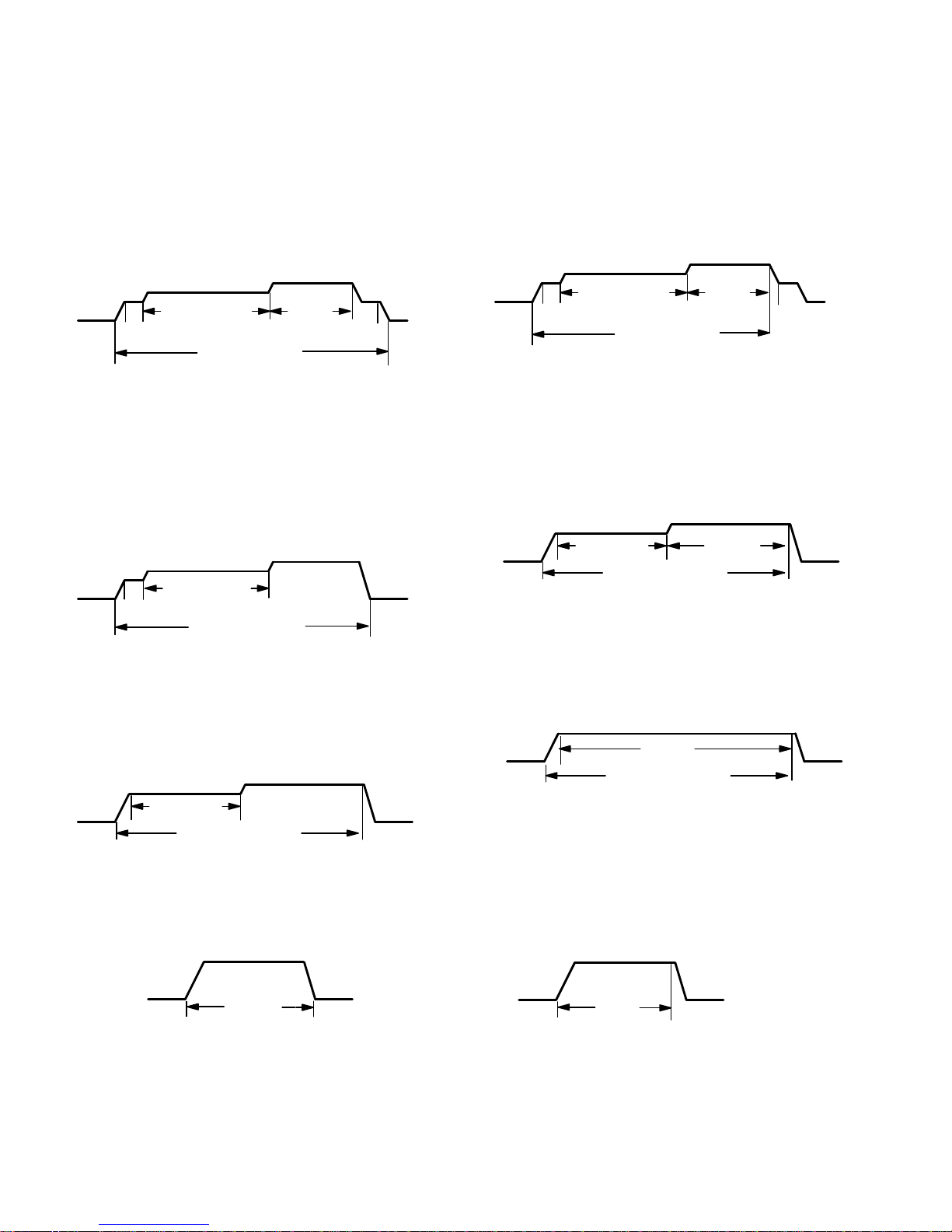
Page 14
G60UHV units manufactured before April 2003
Ramping Option A (Factory Selection)
Motor runs at 50% for 1/2 minute.
Motor then runs at 82% for approximately 7−1/2 min-
utes.
If demand has not been satisfied after 7−1/2 minutes,
motor runs at 100% until demand is satisfied.
Once demand is met, motor runs at 50% for 1/2 min-
ute.
Motor ramps down to off.
OFF
OFF
1/2 MIN
50% CFM
COOLING DEMAND
7−1/2 MIN
82% CFM
100%
CFM
1/2 MIN
50% CFM
Ramping Option B
Motor runs at 50% for 1/2 minute.
Motor then runs at 82% for approximately 7−1/2 min-
utes.
If demand has not been satisfied after 7−1/2 minutes,
motor runs at 100% until demand is satisfied.
Once demand is met, motor ramps down to off.
OFF
OFF
1/2 MIN
50% CFM
7−1/2 MIN
82% CFM
100% CFM
COOLING DEMAND
Ramping Option C
Motor runs at 82% for approximately 7−1/2 minutes.
If demand has not been satisfied after 7−1/2 minutes,
the motor runs at 100% until demand is satisfied.
Once demand is met, motor ramps down to off.
OFF
OFF
82%CFM
100% CFM
COOLING DEMAND
7−1/2 MIN
Ramping Option D
Motor runs at 100% until demand is satisfied.
Once demand is met, motor ramps down to off.
OFFOFF
100% CFM
COOLING
DEMAND
G60UHV units manufactured April 2003 and later
Ramping Option A (Factory Selection)
S Motor runs at 50% for 30 seconds.
S Motor then runs at 82% for approximately
7−1/2 minutes.
S If demand has not been satisfied after 7−1/2 minutes.
Motor runs at 100% until demand is satisfied.
S Once demand is met, motor runs at 50% for 30 sec-
onds then ramps down to stop.
OFF
OFF
1/2 MIN
50% CFM
COOLING DEMAND
7 1/2 MIN
82% CFM
100%
CFM
1/2 MIN
50% CFM
Ramping Option B
S Motor runs at 82% for approximately 7−1/2 minutes. If
demand has not been satisfied after 7−1/2 minutes
motor runs at 100% until demand is satisfied.
S Once demand is met, motor ramps down to stop.
OFF
OFF
82%CFM
100% CFM
COOLING DEMAND
7 1/2 MIN
Ramping Option C
S Motor runs at 100% until demand is satisfied.
S Once demand is met, motor runs at 100% for 45* sec-
onds then ramps down to stop.
OFF
OFF
100% CFM
COOLING DEMAND
* G60UHV units date coded prior to 2−2006 will delay 60 seconds
Ramping Option D
S− Motor runs at 100% until demand is satisfied.
S− Once demand is met, motor ramps down to stop.
OFFOFF
100% CFM
COOLING
DEMAND
Page 15

Page 15
Switches 11 and 12 −− Heating Mode Blower Speed −−
Switches 11 and 12 are used to select heating mode blower
motor speed. The unit is shipped from the factory with the
dip switches positioned for medium low (2) speed indoor
blower motor operation during the heating mode. The table
below provides the heating mode blower speeds that will
result from different switch settings. Refer to blower data
tables at the front of this manual for corresponding cfm values.
TABLE 11
Heating Mode Blower Speeds
Speed
Switch 11 Switch 12
1 − Low On On
2 − Medium Low
(Factory)
Off On
3 − Medium High On Off
4 − High Off Off
On−Board Jumper W914
On−board jumper W914 connects terminals DS and R on
the integrated control board. W914 must be cut when the
furnace is installed with either the Harmony II zone control
board, the CCB1 EfficiencyPlus humidity control or Lennox
SignatureStat. Refer to table 21 for operation sequence
in applications including a G60UHV, CCB1 and single−
speed outdoor unit. Table 22 gives the operation sequence
in applications with a two−speed outdoor unit. Refer to table
23 for operation sequence in applications including a
G60UHV, SignatureStat and single−speed outdoor unit.
Table 24 gives the operation sequence in applications with
a two−speed outdoor unit.
On−Board Jumper W951
On−board jumper W951 connects terminals R and O on the
integrated control board. W951 must be cut when the furnace is installed in applications which include a heat pump
unit and the FM21 FuelMaster control board.
Factory−Installed Jumper Y1 to Y2
A factory−installed jumper from Y1 to Y2 terminals on the
integrated control board terminal strip must be removed if
two−stage cooling will be used.
Diagnostic LEDs (DS1 and DS2)
Two diagnostic LEDs are located on the two−stage, variable speed integrated control just to the left of the first bank
of dip switches. These lights’ flashes correspond with diagnostic codes detailed on in table 6.
Status LEDs (HEAT, HI/LO, ON/OFF and CFM)
The integrated control includes four LEDs which indicate
operating status. The green ON/OFF LED is lit any time the
blower is operating. The green CFM LED indicates the
blower motor speed. Count the number of blinks between
the two−second pauses to determine the CFM. Each blink
represents approximately 100 CFM. The yellow HI/LO LED
is lit when the W914 (DS to R) jumper has not
been clipped
for SignatureStat, CCB1 or Harmony operation. The yellow
HEAT LED is lit when the indoor blower is operating at the
HEATING speed.
Page 16

Page 16
WARNING
Shock hazard.
Disconnect power before servicing. Integrated
Control Board is not field repairable. If control is
inoperable, simply replace entire control.
Can cause injury or death. Unsafe operation will
result if repair is attempted.
5. Integrated Control Board(A92)
Board 100870
Beginning with G60UHV−7, units are equipped with the
Lennox two−stage, variable speed integrated SureLight
control board. The system consists of a ignition / blower
control board (figures 5 and 6) with control pin designations in tables 12, 13 and 14 and ignitor (figure 13). The
board and ignitor work in combination to ensure furnace
ignition and ignitor durability. The SureLight integrated
board controls all major furnace operations. The board
features a red LED light, for furnace status and troubleshooting. The LED flashes in X" + Y" codes. For example
using table 15 under PRESSURE SWITCH CODES", if
the red LED flashes 2 times, then off for 2 seconds then
flashes 3 times, the low pressure switch is failed open.
Two green LEDs show indoor blower status and CFM. See
Page 21 for more detail. The board also has two 120 volt
accessory terminals rated at (1) one amp each. In addition
there is a 24 volt accessory terminal located on TB1.
Electronic Ignition
At the beginning of the heat cycle the SureLight control
monitors the first stage and second stage combustion air
inducer prove switch. The control will not begin the heating
cycle if the first stage prove switch is closed (by−passed).
Likewise the control will not begin the second stage heating
cycle if the second stage prove switch is closed, and will remain in first stage heat. However, if the second stage prove
switch closes during the first stage heat pre−purge, the control will allow second stage heat. Once the first stage prove
switch is determined to be open, the combustion air inducer is energized on low (first stage) heat speed. When the
differential in the prove switch is great enough, the prove
switch closes and a 15−second pre−purge begins. If the
switch is not proven within 2−1/2 minutes, the control goes
into Watchguard−Pressure Switch mode for a 5−minute re−
set period.
After the 15−second pre−purge period, the SureLight ignitor
warms up for 20 seconds after which the gas valve opens
for a 4−second trial for ignition. The ignitor energizes during
the trial until flame is sensed. If ignition is not proved during
the 4−second period, the control will try four more times with
an inter purge and warm−up time between trials of 35 seconds. After a total of five trials for ignition (including the initial trial), the control goes into Watchguard−Flame Failure
mode. After a 60−minute reset period, the control will begin
the ignition sequence again.
NOTE − Board 100870 provides a regulated 95 volts to
to the ignitor.
Two Stage Operation / Thermostat Selection Jumper
The control can be utilized in two modes: SINGLE−STAGE
thermostat or TWO−STAGE thermostat. The thermostat
selection is made using a dip switch (figure 4) and must be
positioned for the particular application. The dip switch is
factory set on TWO" for use with a two−stage thermostat
with two stage heat. Re−position dip switch to SINGLE" for
use with a single stage thermostat with two stage heat.
While in the single−stage thermostat mode (single dip
switch setting), the burners will always fire on first−stage
heat. The combustion air inducer will operate on low speed
and indoor blower will operate on low heat speed. After a
factory default 10 minute recognition period, the unit will
switch to second stage heat. While in the two−stage thermostat mode (two dip switch setting) the burners will fire on
first−stage heat. The combustion air inducer will operate on
low speed and indoor blower will operate on low heat
speed. The unit will switch to second−stage heat on call
from the indoor thermostat. If there is a simultaneous call
for first and second stage heat, the unit will fire an first stage
heat and switch to second stage heat after 30 seconds of
operation. See Sequence of Operation flow charts in the
back of this manual for more detail.
Page 17
Page 17
FIGURE 5
TWO−STAGE, VARIABLE SPEED INTEGRATED CONTROL BOARD
THERMOSTAT CONNECTIONS (TB1)
1/4" QUICK CONNECT TERMINALS
DIP SWITCH FUNCTIONS
INDOOR
BLOWER DIP
SWITCHES
HEATING
DIP
SWITCHES
DIAGNOSTIC
LEDs
ON−BOARD
LINKS
H= 24V HUMIDIFIER OUTPUT
L= LENNOX SYSTEM OPERATION MONITOR
1= FUTURE USE
NEUTRALS= 120 VAC NEUTRAL
W914
W951
W915
HTG DIP SWITCH(ES) FUNCTION
5 and 6 Cooling Mode Blower Speed
7 and 8 Blower Speed Adjustment
9 and 10 Cooling Mode Blower Ramping Profile
11 and 12 Heating Mode Blower Speed
1 T’stat Heat Stages (single or two−stage)
2 Second Stage ON Delay (single−stage t’stat)
3 and 4 Heating Fan OFF Delay
INDOOR BLOWER
DIP SWITCH(ES)
FUNCTION
1
16
5
12
1
4
ON
ON
9
8
FUTURE
USE
TABLE 12
SureLight Board 5 Pin Terminal Designation
PIN # Function
1 Ignitor
2 Combustion Air Inducer High Speed
3 Combustion Air Inducer Low Speed
4 Combustion Air Inducer Neutral
5 Ignitor Neutral
TABLE 13
SureLight Board 12Pin Terminal Designation
PIN # Function
1 Gas Valve High Fire
2 Second Stage Prove Switch
3 Rollout In
4 Ground
5 24V Hot
6 Primary Limit In
7 Gas Valve Low Stage
8 Gas Valve Common
9 24V Neutral
10 Ground
11 Rollout Switch Out
12 1st Stage Prove Switch
TABLE 14
SureLight Board 16 Pin Blower Control Terminals
PIN # Function
1 Ground
2 Low Heat Speed
3 Ground
4 DELAY" Dip Switch Selection
5 COOL" Dip Switch Selection
6 Y1" Signal
7 ADJUST" Dip Switch Selection
8 Ground
9 0" From Thermostat
10 DS" Output Signal
11 HEAT" Dip Switch Selection
12 24 VAC
13 HIGH HEAT Speed
14 Y2" Signal
15 G"
16 CFM LED
Page 18

Page 18
FIGURE 6
TWO−STAGE, VARIABLE SPEED INTEGRATED CONTROL BOARD
Page 19
Page 19
TABLE 15
FLASH CODE
(X + Y)
STATUS / ERROR DESCRIPTION
FLASH CODE DESCRIPTIONS
Pulse A 1/4 second flash followed by four seconds of off time.
Heartbeat Constant 1/2 second bright and 1/2 second dim cycles.
X + Y
LED flashes X times at 2Hz, remains off for two seconds, flashes Y times at 2Hz, remains off for four
seconds, then repeats.
Pulse Power on − Standby.
Heartbeat Normal operation − signaled when heating demand initiated at thermostat.
FLAME CODES
1 + 2 Low flame current −− run mode.
1 + 3 Flame sensed out of sequence −− flame still present.
PRESSURE SWITCH CODES
2 + 3 Low pressure switch failed open.
2 + 4 Low pressure switch failed closed.
2 + 5 High pressure switch failed open.
2 + 6 High pressure switch failed closed.
2 + 7 Low pressure switch opened during ignition trial or heating demand.
LIMIT CODE
3 + 1 Limit switch open.
WATCHGUARD CODES
4 + 1 Watchguard −− Exceeded maximum number of retries.
4 + 2 Watchguard −− Exceeded maximum number of retries or last retry was due to pressure switch opening.
4 + 3 Watchguard −− Exceeded maximum number of retries or last retry was due to flame failure.
4 + 5 Watchguard −− Limit remained open longer than three minutes.
4 + 6
Watchguard −− Flame sensed out of sequence; flame signal gone.
4 + 7 Ignitor circuit fault −− Failed ignitor or triggering circuitry.
4 + 8 Low line voltage.
HARD LOCKOUT CODES
5 + 1 Hard lockout −− Rollout circuit open or previously opened.
5 + 2 Control failed self check, internal error (control will restart if error recovers).
5 + 3 No Earth ground (control will restart if error recovers).
5 + 4 Reversed line voltage polarity (control will restart if the error recovers).
5 + 6 Low secondary (24VAC) voltage.
Error Code Storage
The ignition control stores the last ten error codes in
memory. The codes are retained in case of power loss.
Error Code Review
1 − Short R (2) to (1). Within 1/2 second, the STATUS LED
will stay lit continuously to indicate that the short was
sensed.
2 − Continue to hold the short between R (2) to (1). After 5
seconds, STATUS LED will go from being continuously
lit to off. This indicates that error code review is
pending.
3 − Remove R (2) to (1) short within ten seconds of STA-
TUS LED turning off. This activates error code review.
4 − Last ten error codes will be flashed on the STATUS
LED.
5 − After final error code is indicated, STATUS LED will
flash to indicate normal operation.
Clearing Error Codes
1 − Short R (2) to (1). Within 1/2 second, the STATUS LED
will stay lit continuously to indicate that the short was
sensed.
2 − Continue to hold the short between R (2) to (1). After 5
seconds, STATUS LED will go from being continuously
lit to off.
3 − Continue to hold the short between R (2) to (1) beyond
ten seconds after STATUS LED has turned off.
STATUS LED will turn on, indicating that error codes
have been cleared.
4 − Remove R (2) to (1) short. STATUS LED will flash to
indicate normal operation.
Page 20
Page 20
Dip Switch Settings
Heating Operation DIP Switch Settings
Switch 1 −− Thermostat Selection −− This unit may be used
with either a single−stage or two−stage thermostat. The
thermostat selection is made using a DIP switch which
must be properly positioned for the particular application.
TheDIP switch is factory−positioned for use with a two−
stage thermostat. If a single−stage thermostat is to be used,
the DIP switch must be repositioned.
a − Select OFF" for two−stage heating operation con-
trolled by a two−stage heating thermostat (factory setting);
b − Select ON" for two−stage heating operation con-
trolled by a single−stage heating thermostat. This setting provides a timed delay before second−stage heat
is initiated.
Switch 2 −− Second Stage Delay (Used with Single−
Stage Thermostat Only) −− This switch is used to deter-
mine the second stage on delay when a single−stage thermostat is being used. The switch is factory−set in the OFF
position, which provides a 10−minute delay before second−
stage heat is initiated. If the switch is toggled to the ON
position, it will provide a 15−minute delay before second−
stage heat is initiated. This switch is only activated when
the thermostat selector jumper is positioned for SINGLE−
stage thermostat use.
Switches 3 and 4 −− Blower−Off Delay −− The blower−on
delay of 45 seconds is not adjustable. The blower−off delay
(time that the blower operates after the heating demand
has been satisfied) can be adjusted by moving switches 3
and 4 on the integrated control board. The unit is shipped
from the factory with a blower−off delay of 90 seconds. The
blower off delay affects comfort and is adjustable to satisfy
individual applications. Adjust the blower off delay to
achieve a supply air temperature between 90° and 110°F at
the exact moment that the blower is de−energized. Longer
off delay settings provide lower supply air temperatures;
shorter settings provide higher supply air temperatures.Table 16 provides the blower off timings that will result
from different switch settings.
TABLE 16
Blower Off Delay Switch Settings
Blower Off Delay
(Seconds)
Switch 3 Switch 4
60 Off On
90 Off Off
120 On Off
180 On On
Indoor Blower Operation DIP Switch Settings
Switches 5 and 6 −− Cooling Mode Blower Speed −−
Switches 5 and 6 are used to select cooling blower motor
speed. The unit is shipped from the factory with the DIP
switches positioned for high speed (4) indoor blower motor
operation during the cooling mode. The table below provides the cooling mode blower speeds that will result from
different switch settings. Refer to blower tables at the front
of this manual for corresponding cfm values.
TABLE 17
Cooling Mode Blower Speeds
Speed
Switch 5 Switch 6
1 − Low On On
2 − Medium Low Off On
3 − Medium High On Off
4 − High (Factory) Off Off
Switches 7 and 8 −− Blower Speed Adjustment −−
Switches 7 and 8 are used to select blower speed adjustment settings. The unit is shipped from the factory with the
DIP switches positioned for NORMAL (no) adjustment.
The DIP switches may be positioned to adjust the blower
speed by +10% or −10% to better suit the application. The
table below provides blower speed adjustments that will result from different switch settings. Refer to blower tables at
the front of this manual for corresponding cfm values.
TABLE 18
Blower Speed Adjustment
Adjustment
Switch 7 Switch 8
+10% (approx.) On Off
NORMAL (Factory) Off Off
−10% (approx.) Off On
Switches 9 and 10 −− Cooling Mode Blower Speed
Ramping −− Switches 9 and 10 are used to select cooling
mode blower speed ramping options. Blower speed ramping may be used to enhance dehumidification performance. The switches are factory set at option A which has
the greatest effect on blower motor performance. Table 19
provides the cooling mode blower speed ramping options
that will result from different switch settings. The cooling
mode blower speed ramping options are detailed on
Page 14 under units manufactured April 2003 and later".
NOTE − The off portion of the selected ramp profile also applies during heat pump operation in dual fuel applications.
TABLE 19
Cooling Mode Blower Speed Ramping
Ramping Option
Switch 9 Switch 10
A (Factory) Off Off
B On Off
C Off On
D On On
Switches 11 and 12 −− Heating Mode Blower Speed −−
Switches 11 and 12 are used to select heating mode blower
motor speed. The unit is shipped from the factory with the
dip switches positioned for medium low (2) speed indoor
blower motor operation during the heating mode. The table
below provides the heating mode blower speeds that will
result from different switch settings. Refer to blower tables
at the front of this manual for corresponding cfm values.
Page 21
Page 21
TABLE 20
Heating Mode Blower Speeds
Speed
Switch 11 Switch 12
1 − Low On On
2 − Medium Low
(Factory)
Off On
3 − Medium High On Off
4 − High Off Off
On−Board Link W914
On−board link W914 is a clippable connection which connects terminals DS and R on the integrated control board.
W914 must be cut when the furnace is installed with either
the Harmony III zone control board or a thermostat which
features humidity control. If the link is left intact the PWM
signal from the HARMONY III control will be blocked and
also lead to control damage. Refer to table 21 (CCB1) or 23
(SignatureStat) for operation sequence in applications
including G60UHV, a thermostat which features humidity
control and a single−speed outdoor unit. Table 22 (CCB1)
and table 24 (SignatureStata) gives the operation sequence in applications with a two−speed outdoor unit.
On−Board Link W951
On−board link W951 is a clippable connection which con-
nects terminals R and O on the integrated control board.
W951 must be cut when the furnace is installed in applications which include a heat pump unit and a thermostat
which features dual fuel use. If the link is left intact, terminal
O" will remain energized eliminating the HEAT MODE in
the heat pump.
On−Board Link W915
On−board link W915 is a clippable connection which connects terminals Y1 and Y2 on the integrated control board.
W915 must be cut if two−stage cooling will be used. If the
link is not cut the outdoor unit will operate in second−stage
cooling only.
Status LEDs (SPEED, CFM, E−COM)
The green SPEED LED indicates circulating blower speed
in response to the DS signal. The LED is lit during normal
blower operation and is off during a dehumidification demand. In Harmony III applications, the brightness of the
LED indicates the requested blower speed.
The green CFM LED indicates the blower air flow. Count
the number of blinks between the two−second pauses to
determine the CFM. Each blink represents approximately
100 CFM.
The green E−COM LED indicates that the control is receiving and processing of commands and inputs. The LED may
flash rapidly or may display a single flash, depending upon
the activity.
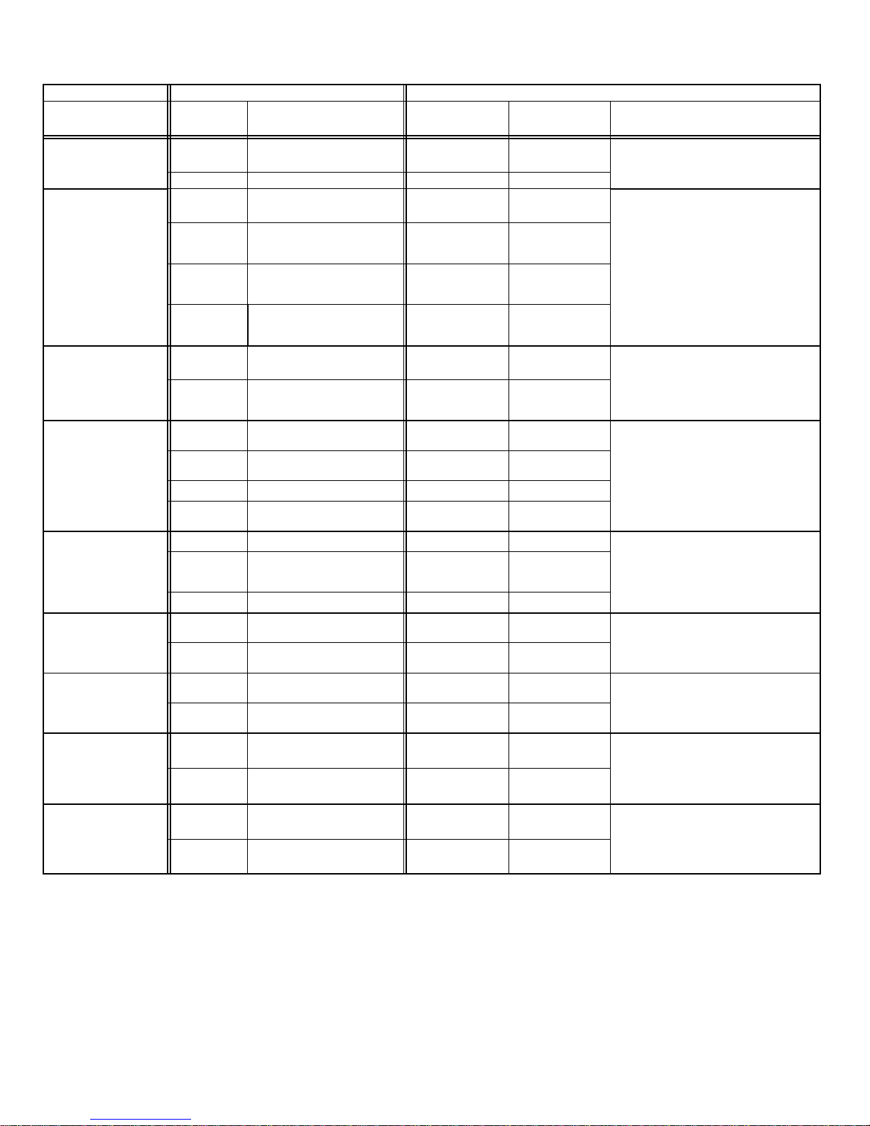
TABLE 21
G60UHV, CCB1 and Single−Speed Outdoor Unit
OPERATING MODE
SYSTEM DEMAND SYSTEM RESPONSE
System Condition
Thermostat
Demand
*Relative Humidity
(EfficiencyPlus Lights)
Blower
CFM
(COOL)
Comments
Normal operation Y1
No demand. Humidity
level is acceptable
COOL
Compressor demand and indoor blower speed
controlled by thermostat demand.
*Call for humidity
removal during
cooling demand
Y1
Humidity level rises above
setpoint. Demand initiated.
60%/65%
of COOL
Call for dehumidification initiated by CCB1 control.
Indoor blower speed reduced by CCB1 control.
Dehumidification
demand satisfied
during cooling demand.
Y1
Humidity level falls below set-
point. No demand
COOL
When humidity demand is satisfied, blower speed
immediately increases to the COOL CFM to hasten the end of the cycle.
Call for cooling after call for
humidity
removal.
None
Humidity level above setpoint.
Demand initiated.
Off
Dehumidification mode begins when relative humidity is greater than setpoint.
Y1
Humidity level above setpoint.
Demand initiated.
60%/65% of
COOL
Humidity demand
satisfied between
thermostat demands (unit
off cycle).
None Over setpoint (1 or more) Off
While unit is not operating (no thermostat demand), slide switch is moved down and back up.
Blower operates at COOL CFM.
Y1 Change to acceptable COOL
NOTE − When changing unit mode of operation from cooling to heating, indicating lights that are on will stay on until the first thermostat heating
demand.
* Reduced blower speed is 65% of COOL for the −36A and −36B units; 60% of COOL for −60C and −60D series units.
Page 22
Page 22
TABLE 22
G60UHV, CCB1 and Two−Speed Outdoor Unit
OPERATING MODE SYSTEM DEMAND SYSTEM RESPONSE
System
Condition
Thermostat
Demand
*Relative Humidity
(EfficiencyPlus Lights)
****Compressor
Speed
Blower CFM
(COOL)
Comments
Normal operation
Y1 No demand. Acceptable Low
**42%/46%/49%
of HIGH COOL
Compressor demand and indoor
blower speed controlled by
thermostat demand
Y2 No demand. Acceptable High HIGH COOL
Call for humidity
removal during
1st−stage cooling
demand
Y1 No demand. Acceptable Low
**42%/46%/49%
of HIGH COOL
Dehumidification mode does not begin
until after initial thermostat demand is
satisfied and new cooling demand is
initiated.
Y1
Humidity level rises slightly
(1) above setpoint. Demand
initiated.
Low
**42%/46%/49%
of HIGH COOL
Demand
satisfied
Humidity level remains
slightly (1) above setpoint.
Demand continues.
Off
Off
Y1
Humidity level remains
slightly (1) above setpoint.
Demand continues.
High
***65%/60% of
HIGH COOL
Significant increase in
humidity during
thermostat cooling
demand.
Y1
No demand. Acceptable
Low
**42%/46%/49%
of HIGH COOL
If humidity rises significantly above setpoint, or if slide switch is moved signifi-
cantly, unit will immediately go into de-
humidification mode (in presence of
thermostat demand).
Y1
Humidity level rises signifi-
cantly (2 or more) above
setpoint. Demand initiated.
High
***65%/60% of
HIGH COOL
Humidity demand
satisfied during
thermostat demand.
Y1
Humidity level
above setpoint.
High
***65%/60% of
HIGH COOL
When humidity demand is satisfied,
blower immediately shifts to the COOL
CFM in order to hasten the end of the
cycle. Unit can only shift out of high
speed compressor operation at begin-
ning of next cycle.
Y1
Humidity level falls below
setpoint. No demand.
High
HIGH COOL
None
No demand. Acceptable
Off
Off
Y1
No demand. Acceptable
Low
**42%/46%/49%
of HIGH COOL
Call for humidity
removal during 2nd
stage thermostat
demand
Y2
No demand. Acceptable
High
HIGH COOL
Blower immediately changes speed in
response to thermostat demand.
Y2
Humidity level rises slightly
(1) above setpoint. Demand
initiated.
High
***65%/60% of
HIGH COOL
Y2
No demand. Acceptable
High
HIGH COOL
*Call for 1st stage
cooling after call for
humidity removal.
None
Humidity level is slightly (1)
above setpoint.
Off
Off
Dehumidification mode (high speed
compressor) begins with next thermo-
stat demand after initial demand is sat-
isfied.
Y1
Humidity level is slightly (1)
above setpoint.
Low
**42%/46%/49%
of HIGH COOL
Call for 2nd stage
cooling after call for
humidity removal
None
Humidity level is slightly (1)
above setpoint.
Off
Off
Reduced blower speed (dehumidifica-
tion speed) begins immediately with
thermostat demand
Y2
Humidity level is slightly (1)
above setpoint.
High
***65%/60% of
HIGH COOL
Call for cooling after
significant increase in
humidity
None
Humidity level is significantly
above setpoint (2 or more).
Off
Off
If humidity increases significantly over
setpoint, or if slide switch is moved,
unit immediately goes into dehumidifi-
cation mode (in presence of thermostat
demand).
Y1 or Y2
Humidity level is significantly
above setpoint (2 or more).
High
***65%/60% of
HIGH COOL
Humidity demand
satisfied between
thermostat demands
(unit off cycle).
None
Humidity level is slightly (1)
above setpoint.
Off
Off
While unit is not operating (no thermo-
stat demand), slide switch is moved
down and back up. Blower and com-
pressor operate at high speed until
next thermostat demand.
Y1 or Y2
Humidity level falls below
setpoint. No demand.
High
HIGH COOL
NOTE − When changing unit mode of operation from cooling to heating, indicating lights that are on will stay on until the first thermostat heating demand.
*IMPORTANT - If power to unit is turned on with CCB1 calling for humidity removal, outdoor unit may be locked into high speed
indefinitely. To reset, move humidity slide switch all the way down then back up to desired setpoint (with unit running)
** Reduced blower speed for ALL model units manufactured September 2002 and later is 49% of HIGH COOL. (Earlier date
code: −42% of HIGH COOL for −36A and −36B units; 46% of HIGH COOL for −60C and −60D series units)
*** Reduced blower speed is 65% of HIGH COOL for −36A and −36B units; 60% of HIGH COOL for −60C and −60D series units.
****If the two−speed control on a two−speed outdoor unit is set for LATCH 2 (15 minutes) or LATCH 3 (30 minutes), the compressor will latch into high speed after a Y1 demand has occurred for that period of time.
Page 23

Page 23
TABLE 23
G60UHV, SignatureStatt and SINGLE STAGE OUTDOOR UNIT
OPERATING
SEQUENCE
SYSTEM DEMAND SYSTEM RESPONSE
System
Condition
Step
Thermostat Demand Relative Humidity
Compres-
sor
Blower
CFM
(COOL)
Comments
Y1 O G
W
1
Status D
NO CALL FOR DEHUMIDIFICATION
Normal Operation 1 On On On Acceptable
24
VAC
High 100%
Compressor and indoor
blower follow thermostat
demand
BASIC MODE (only active on a Y1 thermostat demand)
Normal Operation 1 On On On Acceptable
24
VAC
High 100%
SignatureStat energizes
Y1 and de−energizes D on
a call for de−humidification
Dehumidification
Call
2 On On On On Demand
0
VAC
High
60%, 65%,
70%*
PRECISION MODE (operates independent of a Y1 thermostat demand)
Normal Operation 1 On On On Acceptable
24
VAC
High 100%
Dehumidification mode
begins when humidity is
greater than set point
Dehumidification
call
2 On On On Demand
0
VAC
High
60%, 65%,
70%*
Dehumidification
call ONLY
1 On On On Demand
0
VAC
High
60%, 65%,
70%*
SignatureStat will try to
maintain room humidity
setpoint by allowing the
room space to maintain a
cooler room thermostat
setpoint**
Jumpers at indoor unit with a single stage outdoor unit
With Condensing unit − Cut W914 (R to DS) on SureLight board
With Heat Pump − Cut W914 (R to DS) & W951 (R to O) on SureLight board
Dave Lennox SignatureStat to use for this application − 51M26 1 heat / 1 cool or 51M28 − 2 heat / 2 cool for heat pumps
*Dehumidification blower speed is 65% of COOL speed for 36A & 36B units and 60% COOL speed for 60C & 60D units
manufactured before 09−2002. Dehumidification blower speed is 70% of COOL speed for all units manufactured 09−2002
and later.
**In Precision mode, SignatureStats built before 10−2003 will maintain room temperature up to 3°F(1.8°C) cooler than room
setting. Signature Stats built 10−2003 and later will maintain room temperature up to 2 °F (1.2°C) cooler than room setting.
Page 24

Page 24
TABLE 24
G60UHV, SignatureStatt and TWO STAGE OUTDOOR UNIT
OPERATING
SEQUENCE
SYSTEM DEMAND SYSTEM RESPONSE
System
Condition
Step
Thermostat Demand Relative Humidity
Compressor
Blower
CFM
(COOL)
Comments
Y1 Y2 O G
W1W
2
Status D
NO CALL FOR DEHUMIDIFICATION
Normal Operation −
Y1
1 On On On Acceptable
24
VAC
Low
60%, 65%
70%*
Compressor and indoor
blower follow thermostat
demand
Normal Operation −
Y2
2 On On On On Acceptable
24
VAC
High 100%
ROOM THERMOSTAT CALLS FOR FIRST STAGE COOLING
BASIC MODE (only active on a Y1 thermostat demand)
Normal Operation 1 On On On Acceptable
24
VAC
Low
60%, 65%
70%*
SignatureStat energizes
Y2 and de−energizes D on
a call for de−humidification
Dehumidification
Call
2 On On On On Demand
0
VAC
High
60%, 65%
70%**
PRECISION MODE (operates independent of a Y1 thermostat demand)
Normal Operation 1 On On On Acceptable
24
VAC
Low
60% 65%
70%*
Dehumidification mode begins when humidity is
greater than set point
Dehumidification
call
2 On On On On Demand
0
VAC
High
60% 65%
70%**
Dehumidification
call ONLY
1 On On On On Demand
0
VAC
High
60% 65%
70%**
SignatureStat will try to
maintain room humidity
setpoint by allowing the
room space to maintain a
cooler room thermostat
setpoint***
ROOM THERMOSTAT CALLS FOR FIRST AND SECOND STAGE COOLING
BASIC MODE (only active on a Y1 thermostat demand)
Normal Operation 1 On On On On Acceptable
24
VAC
High 100%
SignatureStat energizes
Y2 and de−energizes D on
a call for de−humidification
Dehumidification
Call
2 On On On On Demand
0
VAC
High
60% 65%
70%**
PRECISION MODE (operates independent of a Y1 thermostat demand)
Normal Operation 1 On On On Acceptable
24
VAC
Low
60% 65%
70%*
Dehumidification mode begins when humidity is
greater than set point
Dehumidification
call
2 On On On On Demand
0
VAC
High
60% 65%
70%**
Dehumidification
call ONLY
1 On On On On Demand
0
VAC
High
60% 65%
70%**
SignatureStat will try to
maintain room humidity
setpoint by allowing the
room space to maintain a
cooler room thermostat
setpoint***
Jumpers at indoor unit with a two stage outdoor unit
RCut factory jumper from Y1 to Y2 or cut W915 (Y1 to Y2)
With Condensing unit − Cut W914 (R to DS) on SureLight board
With Heat Pump − Cut W914 (R to DS) & W951 (R to O) on SureLight board
Dave Lennox SignatureStat to use for this application − 51M27 2 heat / 2 cool or 51M28 − 2 heat / 2 cool for heat pumps
*Normal operation first stage cooling blower speed is as follows for units built before 09−2002: 65% of COOL for 36A, 36B,
60% COOL for 60C, 60D units. ALL units built 09−2002 and later first stage blower speed is 70% COOL speed.
**Dehumidification blower speed is as follows for units built before 09−2002: 65% of COOL for 36A, 36B 60% of COOL for
60C, 60D. ALL units built 09−2002 and later, reduced blower speed is 70% of COOL.
***In Precision mode, Signature Stats built before 10−2003 will maintain room temperature up to 3°F(1.8°C) cooler than room
setting. Signature Stats built 10−2003 and later will maintain room temperature up to 2 °F (1.2°C) cooler than room setting.
Page 25

Page 25
6. Blower Motor Figure 7
WARNING
During blower operation, the ECM motor emits energy that may interfere with pacemaker operation. Interference is reduced by both the sheet metal cabinet
and distance.
FIGURE 7
SUPPLY AIR BLOWER
BLOWER
MOTOR (B6)
To Remove Blower From Unit: Remove Bolts and
Wiring Jackplugs. Then Slide Out Front of Unit.
POWER
CHOKE
(L13)
BLOWER
WHEEL
Blower Motor (B3)
G60UHV units use a three-phase, electronically controlled
D.C. brushless motor (controller converts single phase a.c. to
three phase D.C.), with a permanent-magnet-type rotor (fig-
ure 8). Because this motor has a permanent magnet rotor it
does not need brushes like conventional D.C. motors. Inter-
nal components are shown in figure 9. The stator windings
are split into three poles which are electrically connected to the
controller. This arrangement allows m o t o r winding s to turn
on and off in sequence by the controller.
FIGURE 8
G60UHV BLOWER MOTOR B3
MOTOR
CONTROLLER
SHAFT
J49
J48
G60UHV BLOWER MOTOR COMPONENTS
FIGURE 9
STATOR
(WINDINGS)
OUTPUT
SHAFT
BEARING
ROTOR
A solid-state controller is permanently attached to the
motor. The controller is primarily an A.C. to D.C. converter. Converted D.C. power is used to drive the motor.
The controller contains a microprocessor which monitors varying conditions inside the motor (such as motor
workload).
The controller uses sensing devices to sense what position
the rotor is in at any given time. By sensing the position of the
rotor and then switching the motor windings on and off in sequence, the rotor shaft turns the blower.
All G60UHV blower motors use single phase power. An
external run capacitor is not used. The motor uses permanently lubricated ball-type bearings.
Internal Operation
Each time the controller switches a stator winding (figure 9) on
and off, it is called a pulse." The length of time each pulse
stays on is called the pulse width." By varying the pulse width
(figure 11), the controller varies motor speed (called pulsewidth modulation"). This allows for precise control of motor
speed and allows the motor to compensate for varying load
conditions as sensed by the controller. In this case, the controller monitors the static workload on the motor and varies motor
rpm in order to maintain constant airflow (cfm).
The motor controller is driven by the Two−stage Variable
Speed Integrated control board. The board receives its
demand (PWM signal or fixed 24 VAC or VDC signal) from
optional controls such as the Harmony zone control system,
Efficiency Plus Humidity Control (CCB1) or a conventional
thermostat.
Motor rpm is continually adjusted internally to maintain
constant static pressure against the blower wheel. The controller monitors the static work load on the motor and motor ampdraw to determine the amount of rpm adjustment. Blower rpm
may be adjusted any amount in order to maintain a constant
cfm as shown in Blower Ratings Tables. The cfm remains relatively stable over a broad range of static pressure. Since the
blower constantly adjusts rpm to maintain a specified cfm, motor rpm is not rated. Hence, the terms cool speed" , heat
speed " or speed tap" in this manual, on the unit wiring diagram and on blower B3, refer to blower cfm regardless of motor rpm.
When Harmony is used, speed taps are overridden and a
PWM signal generated by the Harmony controller continuously varies motor speed based upon zone demands.
Page 26

Page 26
Initial Power Up
When line voltage is applied to B3, there will be a large inrush
of power lasting less than 1/4 second. This inrush charges a
bank of DC filter capacitors inside the controller. If the disconnect switch is bounced when the disconnect is closed, the disconnect contacts may become welded. Try not to bounce the
disconnect switch when applying power to the unit.
Motor Start-Up
When B3 begins start-up, the motor gently vibrates back and
forth for a moment. This is normal. During this time the electronic controller is determining the exact position of the rotor.
Once the motor begins turning, the controller slowly eases
the motor up to speed (this is called soft-start"). The motor
may take as long as 10-15 seconds to reach full speed. If the
motor does not reach 200rpm within 13 seconds, the motor
shuts down. Then the motor will immediately attempt a restart. The shutdown feature provides protection in case of a
frozen bearing or blocked blower wheel. The motor may attempt to start eight times. If the motor does not start after the
eighth try, the controller locks out. Reset controller by momentarily turning off power to unit.
The DC filter capacitors inside the controller are connected
electrically to the speed tap wires. The capacitors take
approximately 5 minutes to discharge when the disconnect
is opened. For this reason it is necessary to wait at least 5
minutes after turning off power to the unit before attempting to change speed taps.
DANGER
Disconnect power from unit and
wait at least five minutes to allow
capacitors to discharge before attempting to adjust motor speed tap
settings. Failure to wait may cause
personal injury or death.
External Operation (Speed Tap Priority)
Figure 10 shows the two quick-connect jacks (J48 and J49)
which connect the motor to the G60UHV. Jack J48 is the
power plug and jack J49 connects the unit controls to the
motor.
Line voltage must be applied to J48 pin 5 in order for the
motor to operate. When using 120VAC pins 1 and 2 must
be jumpered. When control voltage is applied to J49 pin 3
and 15, the motor is energized on the continuous fan mode.
When voltage is applied to J49 pin 2 in addition to pin 3 and
15 (first stage heating), the blower is energized on the low
speed heating tap. When voltage is applied to J49 pin 13 in
addition to pin 3 and 15 (second stage heating), the blower
is energized on the high speed heating tap. The motor assigns priority to J49 pin 2 so that if a call for cooling and a call
for heating are concurrent, heating call overrides and the blower operates on high speed heating tap.
FIGURE 10
POWER
CONNECTOR J48
CONTROL
CONNECTOR J49
BLOWER B3 HARNESS CONNECTORS
J49
PIN 1 - C1
PIN 2 - W / W1
PIN 3 - C2
PIN 4 − Delay
PIN 5 - Cool
PIN 6 - Y1
PIN 7 - Adjust
PIN 8 - 0ut
PIN 9 - 0
PIN 10 - DS(PWM)
PIN 11 - Heat
PIN 12 - R
PIN 13 - EM / W2
PIN 14 - Y / Y2
PIN 15 - G
PIN 16 - Out +
J48
PIN 1 - Jumper PIN 1 to PIN2 for 120VAC line input only.
PIN 2 - Jumper PIN 1 to PIN2 for 120VAC line input only.
PIN 3 - Ground
PIN 4 - AC Line
PIN 5 - AC Line
1
Power Choke (L13)
A choke coil is used on G60UHV 5 ton 1 hp units. The
ch oke i s located on the blower housing and is used to suppress transient current spikes.
Precautions
If the G60UHV or its electronically controlled blower motor is
improperly or inadequately grounded, it may cause television
interference (commonly known as RFI or radio frequency interference).
This interference is caused by internal switching frequencies of the motor controller. TV interference may
show u p as s mall s p ecks o r line s which randomly appear
on the TV screen accompanied by pops or clicks in the sound.
Before attempting any service, make sure the indoor unit is
causing the interference. To check, disconnect power to indoor
unit then check TV for continued signs of interference.
TV interference may be stopped by making sure the motor is solidly grounded to the cabinet (metal to metal) and
by making sure the cabinet is solidly grounded. If TV interference persists, make sure the television (and all affected RF appliances) are moved away from the G60UHV.
Also make sure affected appliances are connected to a separate electrical circuit.
Page 27

Page 27
One revolution
ЗЗЗЗЗЗЗЗЗЗЗЗЗЗЗЗЗ
FIGURE 11
HIGH SPEED COOL (output from controller to motor windings)
MOTOR SPEED CONTROL WITH D.C. PULSE-WIDTH MODULATION
WINDING #1
WINDING #2
WINDING #3
LOW SPEED HEAT/COOL (output from controller to motor windings)
HIGH SPEED HEAT (output from controller to motor windings)
O volts
325VDC
One revolution
O volts
325VDC
O volts
325VDC
WINDING #1
WINDING #2
WINDING #3
O volts
325VDC
O volts
325VDC
O volts
325VDC
WINDING #1
WINDING #2
WINDING #3
O volts
325VDC
O volts
325VDC
O volts
325VDC
Motor speed is determined by the size of the electrical pulse sent to
the motor windings. The longer the pulse, the faster the motor.
One
Pulse
ON PULSE
OFF PULSE
WINDINGS TURNED OFF
The frequency of the pulses to the windings is 20KHz.
DO NOT ATTEMPT TO MEASURE THESE VOLTAGES.
WINDINGS TURNED ON
OUTPUT FROM CONTROLLER TO MOTOR WINDINGS
One revolution
Page 28

Page 28
7. Ignitor
The SureLight ignitor is made of durable silicon nitride. Ignitor longevity is enhanced by controlling voltage to the ignitor. Boards 18M49 and 49M59 find the lowest ignitor temperature which will successfully light the burner, thus increasing the life of the ignitor. Due to this feature of the
board, voltage cannot be measured so ignitor must be
ohmed. Board 100870 provides a regulated 95 volts to the
ignitor for consistent ignition and long ignitor life. Ohm value for ignitors with SureLight boards 18M99 and 49M59
should be 10.9 to 19.7. Ohm value for ignitors with board
100870 should be 25 to 47. See figure 12 and 13 (make
note of control board used) for ignitor location. Ignitors are
not interchangeable between boards.
NOTE − The G60UHV(X) furnace contains electronic
components that are polarity sensitive. Make sure that
the furnace is wired correctly and is properly grounded.
8. Flame Sensor
A flame sensor is located on the left side of the burner support. See figure 14 and 15 (make note of control board
used). The sensor is mounted on the flame rollout plate and
the tip protrudes into the flame envelope of the left−most
burner. The sensor can be removed for service without removing any part of the burners. During operation, flame is
sensed by current passed through the flame and sensing
electrode. The SureLight control allows the gas valve to remain open as long as flame signal is sensed.
FIGURE 12
5/16"
13/32’
5/8
"
SureLight Board 18M99 & 49M59 Ignitor Location
BURNERS TOP VIEW
BURNERS FRONT VIEW
MEASUREMENT IS TO
I.D. OF RETENTION
RING
IGNITOR
BRACKET
FIGURE 13
21/64"
7/32’
5/8
"
SureLight Board 100870 Ignitor Location
BURNERS TOP VIEW
BURNERS FRONT VIEW
MEASUREMENT IS TO
I.D. OF RETENTION
RING
IGNITOR
BRACKET
Page 29

Page 29
FIGURE 14
NORMAL FLAME SIGNAL > 0.23 MICROAMPS
LOW FLAME SIGNAL < 0.22 MICROAMPS
DROP OUT SIGNAL = 0.16 MICROAMPS
5/16"
SureLight Board 18M99 & 49M59 Sensor
FIGURE 15
NORMAL FLAME SIGNAL > 1.50 MICROAMPS
LOW FLAME SIGNAL <
1.40 MICROAMPS
DROP OUT SIGNAL = 0.20 MICROAMPS
5/16"
SureLight Board 100870 Sensor
9. Combustion Air Inducer (B6)
All G60UHV(X) units use a two−stage combustion air inducer to move air through the burners and heat exchanger during heating operation. The blower uses a 120VAC motor.
The motor operates during all heating operation and is controlled by furnace / blower control A92. The inducer also
operates for 15 seconds before burner ignition (pre-purge)
and for 5 seconds after the gas valve closes (post-purge).
The inducer operates on low speed during first−stage heat,
then switches to high speed for second stage heat.
A proving switch connected to the combustion air inducer orifice plate is used to prove inducer operation. The combustion
air inducer orifice will be different for each model. See table
25 for orifice sizes. The switch monitors air pressure in the inducer housing. During normal operation, the pressure in the
housing is negative. If pressure becomes less negative (signifying an obstruction) the proving switch opens. When the
proving switch opens, the furnace control (A92) immediately
closes the gas valve to prevent burner operation.
TABLE 25
G60UHV(X) Unit
C.A.I. Orifice Size
−070 1.5"
−090 1.75"
−110 2.0"
−135 2.25"
Horizontal Applications
The G60UHV(X) furnace can be installed in horizontal applications.
The combustion air inducer may be rotated clockwise or
counterclockwise by 90° to allow for vertical vent discharge
in a horizontal application. Remove the four mounting
screws, rotate the assembly (assembly consists of orifice
plate, proving switch, gasket and combustion air inducer),
then reinstall the mounting screws. See figure 16. Use the
provided wire tie to bundle the pressure switch wires with
the inducer motor power leads. Route the wires away
from moving parts and the heat of the inducer motor to
prevent damage to the wires. Use sheet metal shears to
remove the cut out from the side of the cabinet. See figure
17. Use the two provided sheet metal screws to install the
cut out on the top cap to cover the original flue outlet opening.
Combustion Air Inducer
(Upflow Position)
Mounting Screws
MOUNTING SCREWS
90°
90°
(Remove)
(Remove)
Power Leads
Flue Transition
(Do not remove
)
FIGURE 16
Page 30

Page 30
Flue Outlet Hole
(
Reattach
Cutout Here)
Supply Air
Opening
Top View of Furnace
Top Cap
Cut out
Optional
Flue Outlet
Optional Flue Outlet
(Horizontal Installation)
FIGURE 17
10. Flame Rollout Switches (S47)
Flame rollout switch is a high temperature limit located on
top of the burner box. Each furnace is equipped with two
identical switches. One switch is located over the leftmost
burner and the other switch is located over the rightmost
burner. The limit is a N.C. SPST manual-reset limit connected in series with the primary limit S10. When S47
senses rollout, the circuit breaks and the ignition control immediately stops ignition and closes the gas valve.
If unit is running and flame rollout is detected, the gas valve
will close and ignition control will be disabled. Rollout can
be caused by a blocked heat exchanger, flue or lack of
combustion air. The switch is factory set to trip (open) at
210°F and cannot be adjusted. The switch can be manually
reset. To manually reset a tripped switch, push the reset button located on the control.
11. Primary Limit Control (S10)
The primary limit (S10) on G60UHV(X) units is located in the
heating vestibule panel. When excess heat is sensed in the
heat exchanger, the limit will open. If the limit is open, the furnace control energizes the supply air blower and closes the
gas valve. The limit automatically resets when unit temperature returns to normal. The switch must reset within three minutes or the SureLight board will go into Watch guard for one
hour. The switch is factory set and cannot be adjusted. The
switch may have a different set point for each unit model
number. If limit switch must be replaced, call Lennox Repair
Parts for correct length and set point.
12. Secondary Limit Controls (S21)
The secondary limit (S21) on G60UHV(X) units is located in
the blower compartment on the back side of the blower housing. See figure 1. Blower speed chart on the wiring diagram
show secondary limit quantities per unit. When excess heat is
sensed in the blower compartment, the limit will open. If the
limit is open, the furnace control energizes the supply air blower and closes the gas valve. The limit automatically resets
when unit temperature returns to normal. G60UHV−1 and −2
units use a surface type limit factory set to open at 125°F.
G60UHV−3 units and later use an airstream type limit factory
set to open at 135°. The secondary limit cannot be adjusted.
13. Gas Valve
The G60UHV(X) uses a two−stage gas valve manufactured
by White Rodgers or Honeywell (figures 18 and 19). The
valve is internally redundant to assure safety shut−off. If the
gas valve must be replaced, the same type valve must be
used.
24VAC terminals and gas control knob or switch are located
on the valve. All terminals on the gas valve are connected to
wires from the electronic ignition control. 24V applied to the terminals energizes the valve.
Inlet and outlet pressure taps are located on the valve. A regulator adjustment screw is located on the valve.
LPG change over kits (Honeywell valve only) are available
from Lennox. Kits include burner orifices and a gas valve regulator conversion kit.
Page 31

Page 31
14. Combustion Air Inducer
Prove Switch (S18)
G60UHV(X) series units are equipped with a dual combustion air proving switch (first and second stage) located on
the combustion air inducer orifice bracket. The switch is connected to the combustion air inducer housing by means of a
flexible silicone hose. It monitors negative air pressure in the
combustion air inducer housing.
The switches are a single-pole single-throw proving switch
electrically connected to the furnace control. The purpose of
the switch is to prevent burner operation if the combustion
air inducer is not operating or if the flue becomes obstructed.
On heat demand (first or second stage) the switch senses
that the combustion air inducer is operating. It closes a circuit to the furnace control when pressure inside the combustion air inducer decreases to a certain set point.
Set points vary depending on unit size. See tables 26, 27
and 28. The pressure sensed by the switch is negative relative to atmospheric pressure. If the flue becomes obstructed during operation, the switch senses a loss of negative pressure (pressure becomes more equal with atmospheric pressure) and opens the circuit to the furnace control and gas valve. A bleed port on the switch allows relatively dry air in the vestibule to purge switch tubing, to prevent condensate build up.
The switch is factory set and is not field adjustable. It is a
safety shut-down control in the furnace and must not be by−
passed for any reason. If switch is closed or by−passed, the
control will not initiate ignition at start up.
TABLE 26
0’ to 4500’
G60UHV(X) Unit
Set Point High
Heat
Set Point Low
Heat
−070 0.40" 0.20"
−090 0.45" 0.20"
−110 0.50" 0.20"
−135 0.50" 0.20"
TABLE 27*
4501’ to 7500’
G60UHV(X) Unit
Set Point High
Heat
Set Point Low
Heat
−070 0.40" 0.20"
−090 0.40" 0.20"
−110 0.45" 0.20"
−135 0.45" 0.20"
*Unit requires conversion kit at this altitude. See High Altitude table.
TABLE 28*
7501’ to 10,000’
G60UHV(X) Unit
Set Point High
Heat
Set Point Low
Heat
−070 0.35" 0.20"
−090 0.35" 0.20"
−110 0.40" 0.20"
−135 0.40" 0.20"
*Unit requires conversion kit at this altitude. See High Altitude table.
Page 32

Page 32
II−PLACEMENT AND INSTALLATION
Make sure unit is installed in accordance with installation
instructions and applicable codes.
III−START-UP
A−Preliminary and Seasonal Checks
1 − Inspect electrical wiring, both field and factory installed
for loose connections. Tighten as required.
2 − Check voltage at disconnect switch. Voltage must be
within range listed on the nameplate. If not, consult the
power company and have voltage condition corrected
before starting unit.
B−Heating Start-Up
WARNING
Shock and burn hazard.
G60UHV(X) units are equipped with a hot surface
ignition system. Do not attempt to light manually.
1 − STOP! Read the safety information at the beginning of
this section.
2 − Set the thermostat to the lowest setting.
3 − Turn off all electrical power to the unit.
4 − This furnace is equipped with an ignition device which
automatically lights the burners. Do not try to light the
burners by hand.
5 − Remove the upper access panel.
6 − White Rodgers 36E Gas Valve − Switch gas valve le-
ver to OFF. See figure 18.
Honeywell VR8205 Gas Valve − Turn knob on gas
valve clockwise
to OFF. Do not force. See figure
19.
7 − Wait five minutes to clear out any gas. If you then smell
gas, STOP! Immediately call your gas supplier from a
neighbor’s phone. Follow the gas supplier’s instruc-
tions. If you do not smell gas go to next step.
FIGURE 18
WHITE RODGERS 36E SERIES GAS VALVE
GAS VALVE SHOWN IN OFF POSITION
HIGH FIRE
MANIFOLD
PRESSURE
ADJUSTMENT
ON SIDE
(under cap)
MANIFOLD
PRESSURE
TAP ON SIDE
INLET PRESSURE
TAP ON SIDE
LOW FIRE MANIFOLD
PRESSURE ADJUSTMENT
ON SIDE (under cap)
FIGURE 19
HONEYWELL VR8205 Series Gas Valve
GAS VALVE SHOWN IN OFF POSITION
MANIFOLD
PRESSURE
TAP
lOW FIRE
ADJUSTMENT
SCREW
(under cap)
INLET PRESSURE TAP
HIGH FIRE
ADJUSTMENT
SCREW
(under cap)
8 − White Rodgers 36E Gas Valve − Switch gas valve lever
to ON. See figure 18.
Honeywell VR8205 Gas Valve − Turn knob on gas
valve counterclockwise
to ON. Do not force. See
figure 19.
9 − Replace the upper access panel.
10− Turn on all electrical power to to the unit.
11− Set the thermostat to desired setting.
NOTE − When unit is initially started, steps 1 through 11
may need to be repeated to purge air from gas line.
Turning Off Gas To Unit
1 − Set thermostat to lowest setting.
2 − Turn off all electrical power to unit if service is to be per-
formed.
3 − Remove access panel.
4 − Switch lever on White Rodgers gas valve to OFF; turn
knob on Honeywell valve clockwise
to OFF. Do not
force.
5 − Replace access panel.
C−Safety or Emergency Shutdown
Turn off unit power. Close manual and main gas valves.
D−Extended Period Shutdown
Turn off thermostat or set to UNOCCUPIED" mode. Close
all gas valves (both internal and external to unit) to guarantee no gas leak into combustion chamber. Turn off power to
unit. All access panels and covers must be in place and secured.
Page 33

Page 33
IV−HEATING SYSTEM SERVICE CHECKS
A−C.S.A. Certification
All units are C.S.A. (formally A.G.A. and C.G.A. combined)
design certified without modifications. Refer to the
G60UHV(X) Installation Instruction.
B−Gas Piping
CAUTION
If a flexible gas connector is required or allowed by
the authority that has jurisdiction, black iron pipe
shall be installed at the gas valve and extend outside
the furnace cabinet.
WARNING
Do not exceed 600 in−lbs (50 ft−lbs) torque when
attaching the gas piping to the gas valve.
Gas supply piping should not allow more than 0.5"W.C. drop
in pressure between gas meter and unit. Supply gas pipe
must not be smaller than unit gas connection.
Compounds used on gas piping threaded joints should be
resistant to action of liquefied petroleum gases.
C−Testing Gas Piping
IMPORTANT
In case emergency shutdown is required, turn off
the main shut-off valve and disconnect the main
power to unit. These controls should be properly
labeled by the installer.
When pressure testing gas lines, the gas valve must be disconnected and isolated. Gas valves can be damaged if
subjected to more than 0.5 psig (14" W.C.). See figure 20. If
the pressure is equal to or less than 0.5psig (14"W.C.), use
the manual shut−off valve before pressure testing to isolate
furnace from gas supply.
FIGURE 20
MANUAL MAIN SHUT−OFF VALVE
WILL NOT HOLD TEST PRESSURE
IN EXCESS OF 0.5 PSIG (14"W.C.)
GAS VALVE
CAP
GAS PIPING TEST PROCEDURE
When checking piping connections for gas leaks, use preferred means. Kitchen detergents can cause harmful corrosion on various metals used in gas piping. Use of a specialty
Gas Leak Detector is strongly recommended. It is available
through Lennox under part number 31B2001. See Corp.
8411−L10, for further details.
Do not use matches, candles, flame or any other
source of ignition to check for gas leaks.
D−Testing Gas Supply Pressure
When testing supply gas pressure, connect test gauge to
inlet pressure tap on the gas valve See figure 18 or 19.
Check gas line pressure with unit firing at maximum rate.
Low pressure may result in erratic operation or underfire.
High pressure can result in permanent damage to gas
valve or overfire. See table 29 for operating pressure at unit
gas connection (line).
On multiple unit installations, each unit should be checked
separately, with and without units operating. Supply pressure must fall within range listed in table 29.
E−Check Manifold Pressure
After line pressure has been checked and adjusted, check
manifold pressure. Move pressure gauge to outlet pressure tap located on unit gas valve (GV1). Checks of manifold pressure are made as verification of proper regulator adjustment. Manifold pressure for the G60UHV(X) can be measured at any time the gas valve is open and is supplying gas
to the unit. See table 29 for normal operating manifold pressure. See HIGH ALTITUDE table (table of contents) for high
altitude manifold pressures.
Page 34

Page 34
TABLE 29
All G60UHV Units
Natural LP
Line Pressure WC" 4.5 − 10.5 11.0 − 13.0
Manifold Pressure High
Heat WC"
3.5 10.0
Manifold Pressure Low
Heat WC"
1.7 4.9
IMPORTANT
For safety, connect a shut-off valve between the
manometer and the gas tap to permit shut off of
gas pressure to the manometer.
The gas valve is factory set and should not require adjustment. All gas valves are factory regulated.
Manifold Adjustment Procedure:
1 − Connect a test gauge to manifold pressure tap on gas
valve. See figure 18 or 19 for tap location. Start unit and
allow 5 minutes for unit to reach steady state.
2 − While waiting for the unit to stabilize, notice the flame.
Flame should be stable and should not lift from burner.
Natural gas should burn blue. L.P. gas should burn
mostly blue with some orange streaks.
3 − After allowing unit to stabilize for 5 minutes, record
manifold pressure.
NOTE−Shut unit off and remove manometer as soon as
an accurate reading has been obtained. Take care to replace pressure tap plug.
F− Proper Gas Flow (Approximate)
Furnace should operate at least 5 minutes before checking gas flow. Determine time in seconds for two revolutions of gas through the meter. (Two revolutions assures a
more accurate time.) Divide by two and compare to time
in table 30 below. If manifold pressure matches table 29
and rate is incorrect, check gas orifices for proper size and
restriction.
NOTE− To obtain accurate reading, shut off all other gas
appliances connected to meter.
TABLE 30
GAS METER CLOCKING CHART
G60UH
Unit
Seconds for One Revolution
Natural LP
1 cu ft
Dial
2 cu ft
Dial
1 cu ft
Dial
2 cu ft
DIAL
−70 55 110 136 272
−90 41 82 102 204
−110 33 66 82 164
−135 27 54 68 136
Natural−1000 btu/cu ft LP−2500 btu/cu ft
IMPORTANT
For safety, shut unit off and remove manometer as
soon as an accurate reading has been obtained.
Take care to replace pressure tap plug.
G− Proper Combustion
Furnace should operate minimum 15 minutes with correct
manifold pressure and gas flow rate before checking combustion. See sections E− and F−. Take combustion sample
beyond the flue outlet and compare to the tables below.
The maximum carbon monoxide reading should not exceed 100 ppm.
TABLE 31
High Heat
Unit
CO2%
For Nat
CO2%
For L.P.
G60UHV−36A−070(X) 7.2 − 8.2 8.0 − 9.0
G60UHV−36B−090 7.5 − 8.5 8.5 − 9.5
G60UHV−60C−090(X) 7.5 − 8.5 8.5 − 9.5
G60UHV−60C−110(X) 7.3 − 8.3 8.5 − 9.5
G60UHV−60D−135 7.5 − 8.5 8.8 − 9.8
TABLE 32
Low Heat
Unit
CO2%
For Nat
CO2%
For L.P.
G60UHV−36A−070(X) 4.2 − 5.2 5.0 − 6.0
G60UHV−36B−090 4.7 − 5.7 5.0 − 6.0
G60UHV−60C−090(X) 4.5 − 5.5 5.0 − 6.0
G60UHV−60C−110(X) 4.5 − 5.5 5.3 − 6.3
G60UHV−60D−135 4.7 − 5.7 5.8 − 6.8
Page 35

FIGURE 21
TRANSDUCER
(PART #78H5401)
FIGURE 23
STATIC PRESSURE TEST
Page 35
H−Flame Signal
A microamp DC meter is needed to check the flame signal
on the ignition control.
Flame (microamp) signal is an electrical current which passes
from the furnace control through the sensor during unit operation. Current passes from the sensor through the flame to
ground to complete a safety circuit.
To Measure Flame Signal − Ignition Control:
A transducer (Part
#78H5401 available from
Lennox Repair Parts) is
required to measure flame
signal if meter used will not
read a low micro amp signal. Seefigure21. The
transducer converts microamps to volts on a 1:1 conversion. See figure 14 or 15 for
flame signal. A digital readout meter must b e used. The
transducer plugs into most meters. See figure 22 for
proper use of transducer.
1 − Set the volt meter to the DC voltage scale. Insert
transducer into the VDC and common inputs. Observe correct polarities. Failure to do so results in
negative (−) values.
2 − Turn off supply voltage to control.
3 − Disconnect ignition control flame sensor wire from the
flame sensor.
4 − Connect (−) lead of the transducer to flame sensor.
5 − Connect (+) lead of transducer to the ignition control sen-
sor wire.
6 − Turn supply voltage on and close thermostat contacts to
cycle system.
7 − When main burners are in operation for two minutes, take
reading. Remember 1 DC volt = 1 DC microamp.
SET DIAL TO MEASURE
VDC
(+)
(−) TO
FLAME SENSOR
NOTE−MUST USE DIGITAL METER
RED COLLAR
INDICATES
POSITIVE
LEAD
(+) TO
IGNITION
CONTROL
SENSOR
WIRE
FIGURE 22
(−)
V−TYPICAL OPERATING CHARACTERISTICS
A−Blower Operation and Adjustment
When the thermostat is set to FAN ON," the indoor
blower will run continuously at approximately 38% of
the second−stage cooling speed when there is no cooling or heating demand.
When the G60UHV(X) is running in the heating mode,
the indoor blower will run on the heating speed designated by the positions of dip switches 11 and 12.
When there is a cooling demand, the indoor blower will
run on the cooling speed designated by the positions
of dip switches 5 and 6.
B−Temperature Rise
Temperature rise for G60UHV(X) units depends on unit input, blower speed, blower horsepower and static pressure
as marked on the unit rating plate. The blower speed must
be set for unit operation within the range of TEMP. RISE
°F" listed on the unit rating plate.
To Measure Temperature Rise:
1 − Place plenum thermometers in the supply and return air
plenums. Locate supply air thermometer in the first horizontal run of the plenum where it will not pick up radiant
heat from the heat exchanger.
2 − Set thermostat to highest setting.
3 − After plenum thermometers have reached their high-
est and steadiest readings, subtract the two readings.
The difference should be in the range listed on the unit
rating plate. If the temperature is too low, decrease
blower speed. If temperature is too high, first check the
firing rate. Provided the firing rate is acceptable, increase blower speed to reduce temperature. To
change blower speed taps see the Blower Speed Taps
section in this manual.
C−External Static Pressure
1 − Tap locations shown in figure 23.
2 − Punch a 1/4" diameter hole
in supply and return air plenums. Insert manometer
hose flush with inside edge
of hole or insulation. Seal
around the hose with permagum. Connect the zero end
of the manometer to the discharge (supply) side of the system. On ducted systems, connect the other end of manometer to the return
duct as above. For systems with non−ducted returns,
leave the other end of the manometer open to the atmosphere.
3 − With only the blower motor running and the evaporator
coil dry, observe the manometer reading. Adjust blower motor speed to deliver the air desired according to
the job requirements.
4 − External static pressure drop must not be more than
0.8" W.C.
5 − Seal around the hole when the check is complete.
Page 36

Page 36
VI−MAINTENANCE
WARNING
Disconnect power before servicing unit.
CAUTION
Label all wires prior to disconnection when servicing
controls. Wiring errors can cause improper and dangerous operation. Verify proper operation after servicing.
At the beginning of each heating season, a qualified technician should check the system as follows:
A−Blower
Check the blower wheel for debris and clean if necessary.
The blower motors are prelubricated for extended bearing
life. No further lubrication is needed.
WARNING
The blower access panel must be securely in place
when the blower and burners are operating. Gas
fumes, which could contain carbon monoxide, can
be drawn into living space resulting in personal injury or death.
B−Filters
All G60UHV(X) filters are installed external to the unit. Filters should be inspected monthly. Clean or replace the filters when necessary to ensure that the furnace operates
properly. Replacement filters must be rated for high velocity airflow.
C−Flue and Chimney
Check the flue pipe, chimney and all connections for tightness and to make sure there is no blockage.
D−Electrical
1 − Check all wiring for loose connections.
2 − Check for the correct voltage at the furnace (furnace
operating).
3 − Check amp−draw on the blower motor.
Motor Nameplate__________Actual__________
E−Heat Exchanger and Burners
NOTE − Use papers or protective covering in front of the furnace during cleaning.
Cleaning the heat exchanger requires a steel spring
snake," a reversible drill and a vacuum cleaner. The steel
spring snake may be constructed by purchasing a 4 ft. long
by 1/4 inch diameter steel wire cable and a 1/4 inch diame-
ter wire brush. These items are available at a hardware
store. Insert wire end of brush into the open end of the
spring cable. Crimp the cable around the brush so that the
brush is secured and will not come off during cleaning. Attach the other end of the cable to the reversible drill to complete the tool for cleaning the heat exchanger.
1 − Turn off both electrical and gas power supplies to fur-
nace.
2 − Remove flue pipe and top cap from the unit. Label the
pressure switch wires, then disconnect them.
3 − Remove the four screws that secure the combustion air
inducer. Carefully remove the combustion air inducer to
avoid damaging blower gasket. If gasket is damaged, it
must be replaced to prevent leakage.
G60UHV(X) BURNER & HEAT EXCHANGER REMOVAL
FIGURE 24
HEAT EXCHANGER
BURNER BOX
ASSEMBLY
GAS VALVE
ASSEMBLY
GASKET
4 − Remove the collector box located behind the combus-
tion air inducer. Be careful with the collector box gasket. If the gasket is damaged, it must be replaced to
prevent leakage.
5 − Label the wires from gas valve and rollout switches,
then disconnect them.
6 − Remove the four screws securing the burner box cover
and remove the cover.
7 − Disconnect gas supply piping. Remove six screws se-
curing the burner box / manifold assembly to the vestibule panel and remove the assembly from the unit.
Take care not to damage the gasket.
Page 37

Page 37
NOx INSERTS
(X models only)
FIGURE 25
NOx INSERT
8 − NOx units only − Remove the three screws that attach
the NOx insert to the corbel at the entrance to each
heat exchanger section. Carefully remove the NOx insert from each section. See figure 25.
9 − Insert the brush end of cable snake into the top of one
of the heat exchanger openings. Do not force the
cable into the heat exchanger. Insert the cable and
operate the drill on slow speed. Move the cable in and
out of the heat exchanger section three or four times or
until sufficient cleaning is accomplished. Reverse drill
and slowly work the cable out of opening.
10− Repeat procedure for each heat exchanger section.
11− After each of the top heat exchanger sections has been
cleaned, insert the brush end of the cable snake into
the bottom openings of each of the heat exchanger
sections and clean as described in step 8.
12− Remove the cable from the heat exchanger. Use a vac-
uum cleaner to remove debris knocked loose during
cleaning.
NOTE − Safety glasses and surgical mask should
be worn when using vacuum cleaner.
13− Attach the exhaust end (positive pressure) of the vacu-
um cleaner to the top of the heat exchanger section.
Any loose debris will be forced to the bottom of the heat
exchanger section. Vacuum debris from bottom open-
ings.
14− Replace collector box and combustion air inducer.
Check gaskets for damage. Damaged gaskets must be
replaced to avoid heat exchanger leaks. Replace all
screws to the collector box and combustion air inducer.
Failure to replace all screws may cause leaks.
15− To clean the burner, run a vacuum cleaner with a soft
brush attachment over the face of burners. Visually inspect inside the burners and crossovers for any blockage
caused by foreign matter. Remove any blockage.
16− NOx units only − Reattach the NOx inserts to the cor-
bels at the entrance to each heat exchanger opening.
See figure 25.
17− Re−install gasket and burner box / manifold assembly
onto the vestibule panel. Replace burner box cover
and re−secure using screws.
NOTE − Gasket must be replaced if it was damaged
during disassembly.
18− Reconnect wires to pressure switch, roll−out switches,
gas valve and combustion air inducer. Refer to unit wiring diagram.
19− Re−install top cap and re−secure vent pipe to combus-
tion air inducer outlet.
20− Reconnect gas supply piping.
21− Turn on power and gas supply to unit.
22− Set thermostat and check for proper operation.
23− Check all piping connections, factory and field, for gas
leaks. Use a leak detecting solution or other preferred
means.
CAUTION
Some soaps used for leak detection are corrosive to
certain metals. Carefully rinse piping thoroughly after leak test has been completed. Do not use
matches, candles, flame or other sources of ignition
to check for gas leaks.
24− If a leak is detected, shut gas and electricity off and
repair leak.
25− Repeat steps 23 and 24 until no leaks are detected.
26− Replace front access panel.
Page 38

Page 38
VII− Wiring and Sequence of Operation
A−Wiring Diagram for G60UHV−1, −2 and −3 units
Page 39

Page 39
B−Sequence of Operation
Sequence depends on type thermostat used. G60UHV
units are applicable for single stage or two stage ther-
mostats. Both type thermostats are described below.
Thermostat jumper E20 dictates which mode unit will
operate in. See flow chart for more sequence detail.
SureLight Control Self Check
When there is a call for heat, the SureLight integrated control runs a self check. The control checks for S10 primary
limit, S21 secondary limit (s) and S47 rollout switch normally closed contacts. The control also checks for S102
high heat and S128 low heat prove switch normally open
contacts. Once self check is complete and all safety
switches are operational, heat call can continue.
Two−Stage Thermostat, Two Stage Heat. Jumper E20
set at TWO".
1− SureLight control energizes combustion air inducer B6
on low heat speed. Combustion air inducer runs until
S128 low heat prove switch contacts close (switch
must close within 2 1/2 minutes or control goes into
Watchguard Pressure Switch mode. High heat prove
switch S102 may also close). A 15 second pre−purge
follows once S128 closes.
2− SureLight control begins 20 second ignitor warm up
period.
3− Gas valve opens on first stage for a 4 second trial for
ignition. Ignitor stays energized during the trial or until
flame sensed.
4− Flame is sensed, gas valve remains on first stage heat,
ignitor de−energizes.
5− After 45 second delay, indoor blower B3 is energized
on low heat speed.
The furnace will stay in this mode until first stage de-
mand is satisfied OR a second stage heat demand is
initiated.
6− Second stage heat demand initiated. A 30 second sec-
ond stage recognition period begins.
7− The combustion air inducer ramps up to high heat
speed.
8− S102 high heat prove switch closes and the gas valve
energizes second stage heat.
9− B3 indoor blower ramps up to high heat speed.
Single−Stage Thermostat, Two Stage Heat. Jumper
E20 set at SINGLE"
1− SureLight control energizes combustion air inducer B6
on low heat speed. Combustion air inducer runs until
S128 low heat prove switch contacts close (switch
must close within 2 1/2 minutes or control goes into
Watchguard Pressure Switch mode. High heat prove
switch S102 may also close). A 15 second pre−purge
follows once S128 closes.
2− SureLight control begins 20 second ignitor warm up
period.
3− Gas valve opens on first stage for a 4 second trial for
ignition. Ignitor stays energized during the trial or until
flame sensed.
4− Flame is sensed, gas valve remains on first stage heat,
ignitor de−energizes.
5− After 45 second delay, indoor blower B3 is energized
on low heat speed.
6− A 10 minute (factory set) or 15 minute (field set) second
stage heat delay period begins.
7− After the delay the combustion air inducer ramps up to
high heat speed.
8− S102 high heat prove switch closes and the gas valve
energizes second stage heat.
9− B3 indoor blower ramps up to high heat speed.
Page 40

Page 40
C−Flow Chart SureLight Boards 18M99 & 49M59
HEATING SEQUENCE OF OPERATION
NORMAL AND ABNORMAL HEATING MODE
CONTROL SELF−CHECK OKAY?
YES
GAS VALVE OFF. COMBUSTION AIR INDUCER OFF.
INDOOR BLOWER OFF. (RESET CONTROL BY
TURNING MAIN POWER OFF.) DS1 ON, DS2 ON
NO
POLARITY REVERSED.
DS 1 −− FAST FLASH
DS 2 −− SLOW FLASH
POWER ON
POLARITY OKAY?
NO
SIGNAL HOLDS UNTIL UNIT IS PROPERLY GROUNDED.
DS1 AND DS2 ALTERNATING FAST FLASH.
IS THERE A
PROPER GROUND?
IS VOLTAGE
ABOVE 75 VOLTS?
SIGNAL HOLDS UNTIL VOLTAGE RISES ABOVE 75 VOLTS.
DS1 AND DS2 ALTERNATING FAST FLASH.
NO
YES
NO
YES
GAS VALVE OFF. COMBUSTION AIR INDUCER
OFF. INDOOR BLOWER OFF. CHECK FOR
BROKEN IGNITOR OR OPEN IGNITER CIRCUIT.
DS 1 AND DS 2 ALTERNATING FAST FLASH.
BURNER OFF?
(CONTINUOUS FLAME CHECK)
YES
NO
GAS VALVE OFF. COMBUSTION AIR INDUCER ON.
INDOOR BLOWER ON HEATING SPEED.
DS1 SLOW FLASH, DS2 OFF,
ON/OFF LED OFF
A
NORMAL OPERATION:
DS 1 −− SIMULTANEOUS SLOW FLASH
DS 2 −− SIMULTANEOUS SLOW FLASH
B
THERMOSTAT CALLS FOR HEAT:
DS 1 −− SIMULTANEOUS FAST FLASH
DS 2 −− SIMULTANEOUS FAST FLASH
YES
PRIMARY AND SECONDARY LIMIT
SWITCHES CLOSED?
YES
NO
COMBUSTION AIR INDUCER OFF.
INDOOR BLOWER ON. HAS PRIMARY OR
SECONDARY LIMIT RESET WITHIN 3 MINUTES?
DS1 SLOW FLASH, DS2 ON,
ON/OFF LED ON, HEAT LED ON.
ROLLOUT SWITCH CLOSED?
GAS VALVE OFF. COMBUSTION AIR INDUCER OFF.
HAS MANUAL ROLLOUT SWITCH(ES) BEEN
RESET (CLOSED) WITHIN 3 MINUTES?
DS1 SLOW FLASH, DS2 ON,
ON/OFF LED ON, HEAT LED ON.
NO
YES
FIRST (LOW) STAGE PROVE SWITCH
CONTACTS OPEN?
NO
GAS VALVE OFF. COMBUSTION AIR INDUCER OFF.
INDOOR BLOWER OFF. CONTROL REMAINS UNTIL
PRESSURE SWITCH IS DETECTED OPEN.
DS1 OFF, DS2 SLOW FLASH,
ON/OFF LED OFF, HEAT LED OFF.
YES
GAS VALVE OFF.
COMBUSTION AIR INDUCER OFF.
INDOOR BLOWER OFF.
CONTROL WILL NOT ATTEMPT SECOND−STAGE
OPERATION DURING THIS HEAT DEMAND.
FIRST−STAGE OPERATION WILL BE ATTEMPTED.
DS1 OFF, DS2 FAST FLASH,
ON/OFF LED OFF, HEAT LED ON.
NO
TWO−STAGE OR SINGLE−STAGE THERMOSTAT
CALL FOR HEAT
COMBUSTION AIR INDUCER ON LOW SPEED.
DS1 AND DS2 SIMULTANEOUS FAST FLASH
CONTINUED ON NEXT PAGE
NO
NO
60−MINUTE LIMIT WATCHGUARD MODE.
GAS VALVE OFF, COMBUSTION AIR INDUCER
OFF, INDOOR BLOWER OFF WITH DELAY.
DS1 AND DS2 ALTERNATING SLOW FLASH,
ON/OFF LED OFF, HEAT LED ON.
YES
NO
YES
SECOND (HIGH) STAGE PROVE SWITCH CONTACTS
OPEN?
Page 41

Page 41
HEATING SEQUENCE OF OPERATION
FIRST−STAGE (LOW FIRE) PROVE
SWITCH CLOSED WITHIN 2.5 MINUTES?
GAS VALVE OFF. COMBUSTION AIR INDUCER
OFF. INDOOR BLOWER OFF. UNIT WILL RETRY
AFTER 5−MINUTE WAIT PERIOD.
DS1 OFF, DS2 SLOW FLASH,
ON/OFF LED OFF, HEAT LED OFF.
YES
NO
15−SECOND COMBUSTION AIR INDUCER
PRE−PURGE INITIATED BY CLOSED FIRST−STAGE
PROVE SWITCH (or 15 SECOND INTER−PURGE
PERIOD.)
DS1 AND DS2 SIMULTANEOUS FAST FLASH.
IGNITOR WARM−UP (20 SECONDS)
DS1 AND DS2 SIMULTANEOUS FAST FLASH
IS VOLTAGE ABOVE 75 VOLTS?
NO
COMBUSTION AIR INDUCER OFF, IGNITER OFF.
SIGNAL HOLDS UNTIL VOLTAGE RISES ABOVE 75 VOLTS.
DS1 AND DS2 ALTERNATING FAST FLASH.
YES
IS THERE A PROPER GROUND?
NO
COMBUSTION AIR INDUCER OFF, IGNITER OFF.
SIGNAL HOLDS UNTIL UNIT IS PROPERLY GROUNDED.
DS1 AND DS2 ALTERNATING FAST FLASH.
NO
COMBUSTION AIR INDUCER OFF, IGNITOR OFF.
SIGNAL HOLDS UNTIL IGNITOR IS REPLACED
OR RECONNECTED.
DS1 AND DS2 ALTERNATING FAST FLASH.
YES
AT END OF IGNITOR 20 SECOND WARM UP
PERIOD, 4−SECOND TRIAL FOR IGNITION.
GAS VALVE OPENS, IGNITOR ENERGIZED DURING
4−SECOND TRIAL UNTIL FLAME SENSED.
DS1 AND DS2 SIMULTANEOUS FAST FLASH.
YES
4−SECOND FLAME STABILIZATION PERIOD.
DS1 AND DS2 SIMULTANEOUS FAST FLASH.
FLAME RECTIFICATION CURRENT CHECK
CAN FLAME BE PROVEN WITHIN 4
SECONDS AFTER GAS VALVE OPENS?
(u0.16 microamps)
NO
GAS VALVE OFF. COMBUSTION AIR
INDUCER ON. INDOOR BLOWER OFF.
DS1 SLOW FLASH, DS2 FAST FLASH,
ON/OFF LED OFF, HEAT LED 0N.
HAS CONTROL FAILED TO SENSE
FLAME FOR FIVE CONSECUTIVE TRIES
DURING A SINGLE HEAT DEMAND?
YES
THERMOSTAT CALLS FOR HEAT
DS1 AND DS2 SIMULTANEOUS FAST FLASH
(Refer to box A on previous page)
YES
FLAME PRESENT?
NO
HAS CONTROL RESET IGNITION SEQUENCE
FOUR (4) TIMES?
DS1 SLOW FLASH, DS2 FAST FLASH,
ON/OFF LED OFF, HEAT LED ON .
YES
CONTINUED ON NEXT PAGE
YES
NO
NO
CONTINUED
IS IGNITOR INTACT AND CONNECTED?
WATCHGUARD MODE. GAS VALVE OFF,
COMBUSTION AIR INDUCER OFF.
INDOOR BLOWER OFF.
DS1 AND DS2 ALTERNATING SLOW FLASH.
ON/OFF LED 0FF, HEAT LED OFF.
IS 60−MINUTE RESET PERIOD COMPLETE?
Page 42

Page 42
HEATING SEQUENCE OF OPERATION
LOW FLAME SIGNAL
(Does not affect control operation)
DS1 SLOW FLASH, DS2 FAST FLASH.
FLAME SIGNAL ABOVE
(u
0.23 microamps)
NO
YES
CONTINUED ON NEXT PAGE
YES
SINGLE−STAGE THERMOSTAT MODE
(E20 SET AT SINGLE")
TWO STAGE THERMOSTAT MODE
(E20 SET AT TWO")
YES
YES
START SECOND−STAGE RECOGNITION
ON DELAY (10 OR 15 MINUTES).
DS1 AND DS2 SIMULTANEOUS FAST FLASH.
45−SECOND INDOOR BLOWER ON DELAY BEGINS.
DS1 AND DS2 SIMULTANEOUS FAST FLASH.
YES
YES
PRIMARY AND SECONDARY LIMITS AND ROLLOUT
SWITCHES CLOSED?
NO
GAS VALVE OFF, COMBUSTION AIR INDUCER OFF,
INDOOR BLOWER ON. DS1 SLOW FLASH, DS2 ON,
ON/OFF LED ON, HEAT LED ON.
HAS PRIMARY, SECONDARY OR ROLLOUT
SWITCH CLOSED WITHIN 3 MINUTES?
(Indoor blower on low speed during 3−minute period)
YES
FIRST−STAGE (LOW FIRE)
PROVE SWITCH CLOSED?
LIMIT SWITCH WATCHGUARD MODE.
GAS VALVE OFF, COMBUSTION AIR INDUCER OFF,
INDOOR BLOWER OFF WITH DELAY.
DS1 AND DS2 ALTERNATING SLOW FLASH,
ON/OFF LED OFF, HEAT LED OFF.
IS 60−MINUTE RESET PERIOD COMPLETE?
THERMOSTAT CALLS FOR HEAT.
DS1 AND DS2 SIMULTANEOUS FAST FLASH.
SEE BOX A.
NO
YES
GAS VALVE OFF. COMBUSTION AIR INDUCER ON.
INDOOR BLOWER OFF AFTER DELAY.
DS1 OFF, DS 2 SLOW FLASH,
ON/OFF LED OFF, HEAT LED ON.
NO
YES
C
FIRST−STAGE HEAT DEMAND SATISFIED?
DS1 AND DS2 SIMULTANEOUS SLOW FLASH.
GAS VALVE OFF, COMBUSTION AIR INDUCER
OFF FOLLOWING POST PURGE.
INDOOR BLOWER OFF WITH DELAY
DS1 AND DS2 SIMULTANEOUS SLOW FLASH
YES
SECOND−STAGE HEAT DEMAND.
SECOND−STAGE HEAT DEMAND REQUIRED?
DS1 AND DS2 SIMULTANEOUS SLOW FLASH.
NO
SECOND STAGE PROVE SWITCH CLOSED?
ABNORMAL FLASH CODE.
NOTE − IF SECOND−STAGE PROVE SWITCH
WAS ORIGINALLY FOUND CLOSED,
ABNORMAL CODE WILL FLASH.
SECOND−STAGE PROVE SWITCH CLOSED
AT BEGINNING OF HEAT DEMAND?
DS1 OFF, DS2 SLOW FLASH,
ON/OFF LED ON, HEAT LED ON.
YES
NO
SECOND−STAGE 30−SECOND DELAY ON BEGINS.
DS1 AND DS2 SIMULTANEOUS FAST FLASH
SECOND−STAGE COMBUSTION AIR INDUCER
ON. SECOND−STAGE GAS VALVE ON. HIGH
HEAT INDOOR BLOWER SPEED ON.
DS1 AND DS2 SIMULTANEOUS FAST FLASH.
ON/OFF LED ON.
YES
SECOND−STAGE PROVE SWITCH CLOSED
IN LESS THAN TEN (10) SECONDS?
DS1 AND DS2 SIMULTANEOUS FAST FLASH.
YES
NO
RETURNS TO FIRST−STAGE HEAT MODE WHICH
CONTINUES UNTIL SECOND−STAGE PROVE
SWITCH CAN BE PROVEN or HEAT DEMAND IS
SATISFIED. FIVE (5) MINUTE WAIT PERIOD
INITIATED BEFORE RETRY. WERE 5 ATTEMPTS
MADE FOR SECOND−STAGE HEAT?
YES
NORMAL OPERATION.
DS1 AND DS2 SIMULTANEOUS SLOW FLASH.
SECOND STAGE HEAT DEMAND
DS1 AND DS2 SIMULTANEOUS SLOW FLASH.
NO
YES
NO
YES
CONTINUED
Page 43

Page 43
HEATING SEQUENCE OF OPERATION
IS PRIMARY AND SECONDARY LIMIT
AND ROLLOUT SWITCH CLOSED?
NO
GAS VALVE OFF. COMBUSTION AIR INDUCER OFF.
INDOOR BLOWER ON.
DS1 SLOW FLASH, DS2 ON,
ON/OFF LED ON, HEAT LED 0N.
HAS PRIMARY, SECONDARY OR ROLLOUT
SWITCH CLOSED WITHIN 3 MINUTES?
NO
LIMIT SWITCH WATCHGUARD MODE. GAS VALVE
OFF. COMBUSTION AIR INDUCER OFF. INDOOR
BLOWER OFF WITH DELAY. IS 60−MINUTE RESET
PERIOD COMPLETE? DS SLOW FLASH, DS2 ON,
ON/OFF LED OFF, HEAT LED OFF.
SEE BOX B
THERMOSTAT CALLS FOR HEAT
DS 1 AND DS 2 SIMULTANEOUS FAST FLASH
YES
FIRST−STAGE (LOW FIRE) HEAT
PROVE SWITCH CLOSED?
NO
SEE BOX A
NORMAL OPERATION
DS1 AND DS2 SIMULTANEOUS SLOW FLASH.
YES
YES
GAS VALVE OFF, COMBUSTION AIR INDUCER OFF
AFTER 15 SECOND POST PURGE, INDOOR
BLOWER OFF AFTER DELAY.
DS1 OFF, DS2 FAST FLASH,
ON/OFF LED ON, HEAT LED ON.
RETURN TO HEAT DEMAND?
YES
YES
NO
RETURN TO FIRST−STAGE HEAT MODE.
FIRST−STAGE CONTINUES UNTIL SECOND−
STAGE PROVE SWITCH CAN BE PROVEN or
HEAT DEMAND IS SATISFIED. A FIVE (5) MIN-
UTE WAIT PERIOD IS INITIATED BEFORE
RETRY. WERE 5 ATTEMPTS MADE FOR
SECOND−STAGE HEAT?
YES
NO
SEE BOX C
FIRST−STAGE HEAT DEMAND SATISFIED?
HEAT DEMAND SATISFIED?
DS1 AND DS2 SIMULTANEOUS FAST FLASH.
YES
TWO STAGE THERMOSTAT MODE?
(E20 SET AT TWO")
SINGLE−STAGE THERMOSTAT MODE
(E20 SET AT SINGLE")
YES
YES
HEAT DEMAND SATISFIED?
DS1 AND DS2
SIMULTANEOUS FAST FLASH.
FIRST AND SECOND STAGE HEAT
DEMAND SATISFIED SIMULTANEOUSLY.
DS1 & DS2 SIMULTANEOUS FAST FLASH.
YES
YES
GAS VALVE OFF, COMBUSTION AIR
INDUCER OFF AFTER 5−SECOND
LOW SPEED POST PURGE PERIOD,
INDOOR BLOWER OFF DELAY
INITIATED ON LOW HEAT SPEED.
DS1 AND DS2
SIMULTANEOUS FAST FLASH
DEMAND FOR HEAT SATISFIED.
POWER ON STAND BY.
DS1 AND DS2
SIMULTANEOUS SLOW FLASH
YES
SECOND STAGE HEAT
DEMAND SATISFIED?
DS1 AND DS2
SIMULTANEOUS FAST FLASH.
NO
GAS VALVE, COMBUSTION AIR INDUCER
AND INDOOR BLOWER RETURN TO FIRST−
STAGE OPERATION.
DS1 AND DS2 SIMULTANEOUS FAST FLASH.
YES
FIRST STAGE HEAT DEMAND SATISFIED?
YES
GAS VALVE OFF. COMBUSTION AIR INDUCER
OFF AFTER 5−SECOND LOW SPEED POST−
PURGE PERIOD. INDOOR BLOWER OFF.
DELAY INITIATED ON LOW HEAT SPEED.
DS1 & DS2 SIMULTANEOUS FAST FLASH.
CONTINUED
SECOND−STAGE (HIGH FIRE) HEAT
PROVE SWITCH CLOSED?
Page 44

Page 44
COOLING SEQUENCE OF OPERATION
SIGNAL POLARITY REVERSED.
DS1 FAST FLASH, DS2 SLOW FLASH.
POWER ON
YES
IS POLARITY REVERSED?
THERMOSTAT CALLS FOR FIRST−STAGE COOL.
COMPRESSOR AND CONDENSER FAN
ENERGIZED.
NO
IS THERE
PROPER GROUND?
IS VOLTAGE
ABOVE 75 VOLTS?
LOW VOLTAGE SIGNAL AT DS HOLDS
UNTIL VOLTAGE RISES ABOVE 75 VOLTS.
NO
YES
NO
SIGNAL IMPROPER
GROUND AT DS.
SIGNAL HOLDS
UNTIL UNIT IS
PROPERLY
GROUNDED.
INDOOR BLOWER ENERGIZED ON FIRST STAGE
COOL SPEED AFTER 2 SECOND DELAY.
FIRST−STAGE DEMAND FOR COOL SATISFIED?
NO
THERMOSTAT CALLS FOR SECOND−STAGE COOL.
YES
COMPRESSOR AND CONDENSER FAN DE−ENERGIZED.
INDOOR BLOWER DE−ENEGIZED.
YES
INDOOR BLOWER RAMPS UP TO SECOND−STAGE COOL SPEED.
SECOND−STAGE DEMAND FOR COOL SATISFIED?
YES
UNIT RETURNS TO FIRST STAGE COOL
CONTINUOUS LOW SPEED FAN SEQUENCE OF OPERATION
MANUAL FAN SELECTION MADE AT THERMOSTAT.
AFTER 2 SECOND DELAY, INDOOR BLOWER IS
ENERGIZED ON CONTINUOUS FAN SPEED.
THERMOSTAT CALLS FOR FIRST−STAGE HEAT (W).THERMOSTAT CALLS FOR FIRST STAGE COOL.
YES
YES
AFTER 45−SECOND DELAY, INDOOR BLOWER
SWITCHES TO LOW HEAT SPEED.
FIRST−STAGE HEAT DEMAND SATISFIED.
YES
NO
THERMOSTAT CALLS FOR SECOND−STAGE HEAT (W).
YES
INDOOR BLOWER SWITCHES TO HIGH HEAT SPEED
AFTER 30−SECOND RECOGNITION PERIOD.
SECOND−STAGE HEAT DEMAND SATISFIED.
YES
YES
INDOOR BLOWER RAMPS DOWN TO LOW
HEAT SPEED.
INDOOR BLOWER RAMPS TO FIRST STAGE
COOLING SPEED AFTER A 2−SECOND DELAY.
FIRST−STAGE COOL DEMAND SATISFIED?
YES
NO
SECOND STAGE COOL DEMAND SATISFIED?
INDOOR BLOWER RAMPS TO SECOND
STAGE COOL SPEED
YES
SECOND STAGE COOL DEMAND
INDOOR BLOWER RAMPS DOWN TO FIRST STAGE
COOL SPEED.
YES YES
Page 45

Page 45
D−Wiring Diagram for G60UHV−7 and later
Page 46

Page 46
E−Sequence of Operation
Sequence depends on type thermostat used. G60UHV
units are applicable for single stage or two stage thermostats. Both type thermostats are described below.
Thermostat dip switch selection dictates which mode
unit will operate in. See flow chart for more sequence
detail.
SureLight Control Self Check
When there is a call for heat, the SureLight integrated control runs a self check. The control checks for S10 primary
limit, S21 secondary limit (s) and S47 rollout switch normally closed contacts. The control also checks for S102
high heat and S128 low heat prove switch normally open
contacts. Once self check is complete and all safety
switches are operational, heat call can continue.
Two−Stage Thermostat, Two Stage Heat. Dip Switch
set at TWO".
10− SureLight control energizes combustion air inducer B6
on low heat speed. Combustion air inducer runs until
S128 low heat prove switch contacts close (switch
must close within 2 1/2 minutes or control goes into
Watchguard Pressure Switch mode. High heat prove
switch S102 may also close). A 15 second pre−purge
follows once S128 closes.
11− SureLight control begins 20 second ignitor warm up
period.
12− Gas valve opens on first stage for a 4 second trial for
ignition. Ignitor stays energized during the trial or until
flame sensed.
13− Flame is sensed, gas valve remains on first stage heat,
ignitor de−energizes.
14− After 45 second delay, indoor blower B3 is energized
on low heat speed.
The furnace will stay in this mode until first stage demand is satisfied OR a second stage heat demand is
initiated.
15− Second stage heat demand initiated. A 30 second sec-
ond stage recognition period begins.
16− The combustion air inducer ramps up to high heat
speed.
17− S102 high heat prove switch closes and the gas valve
energizes second stage heat.
18− B3 indoor blower ramps up to high heat speed.
Single−Stage Thermostat, Two Stage Heat. Dip
Switch set at SINGLE"
1− SureLight control energizes combustion air inducer B6
on low heat speed. Combustion air inducer runs until
S128 low heat prove switch contacts close (switch
must close within 2 1/2 minutes or control goes into
Watchguard Pressure Switch mode. High heat prove
switch S102 may also close). A 15 second pre−purge
follows once S128 closes.
2− SureLight control begins 20 second ignitor warm up
period.
3− Gas valve opens on first stage for a 4 second trial for
ignition. Ignitor stays energized during the trial or until
flame sensed.
4− Flame is sensed, gas valve remains on first stage heat,
ignitor de−energizes.
5− After 45 second delay, indoor blower B3 is energized
on low heat speed.
6− A 10 minute (factory set) or 15 minute (field set) second
stage heat delay period begins.
7− After the delay the combustion air inducer ramps up to
high heat speed.
8− S102 high heat prove switch closes and the gas valve
energizes second stage heat.
9− B3 indoor blower ramps up to high heat speed.
Page 47

Page 47
F−Flow Chart SureLight Board 100870
HEATING SEQUENCE OF OPERATION
NORMAL AND ABNORMAL HEATING MODE
CONTROL SELF−CHECK OKAY?
YES
GAS VALVE OFF. COMBUSTION AIR INDUCER OFF.
INDOOR BLOWER OFF. (RESET CONTROL BY
TURNING MAIN POWER OFF.)
NO
POLARITY REVERSED.
STATUS ERROR CODE 5 + 4.
POWER ON
POLARITY OKAY?
SIGNAL HOLDS UNTIL UNIT IS PROPERLY GROUNDED.
STATUS ERROR CODE 5 + 3.
IS THERE A
PROPER GROUND?
NO
YES
A
NORMAL OPERATION:
STATUS LED −− PULSE
B
THERMOSTAT CALLS FOR HEAT:
STATUS LED −− HEARTBEAT
YES
PRIMARY AND SECONDARY LIMIT
SWITCHES CLOSED?
YES
NO
COMBUSTION AIR INDUCER OFF.
INDOOR BLOWER ON. HAS PRIMARY OR
SECONDARY LIMIT RESET WITHIN 3 MINUTES?
STATUS ERROR CODE 3 + 1.
ROLLOUT SWITCH CLOSED?
GAS VALVE OFF. COMBUSTION AIR INDUCER ON.
INDOOR BLOWER ON.
STATUS ERROR CODE 5 + 1.
SEQUENCE HOLDS UNTIL ROLLOUT SWITCH IS
RESET AND MAIN POWER IS INTERRUPTED OR
T’STAT IS CYCLED OFF/ON FOR 3 SEC. MINIMUM.
NO
YES
FIRST (LOW) STAGE PRESSURE SWITCH
CONTACTS OPEN?
NO
GAS VALVE OFF. COMBUSTION AIR INDUCER OFF.
INDOOR BLOWER OFF. CONTROL REMAINS UNTIL
PRESSURE SWITCH IS DETECTED OPEN.
STATUS ERROR CODE 2 + 4
YES
GAS VALVE OFF.
COMBUSTION AIR INDUCER OFF.
INDOOR BLOWER OFF.
CONTROL WILL NOT ATTEMPT SECOND−STAGE
OPERATION DURING THIS HEAT DEMAND.
FIRST−STAGE OPERATION WILL BE ATTEMPTED.
STATUS ERROR CODE 2 + 6.
NO
TWO−STAGE OR SINGLE−STAGE THERMOSTAT
CALL FOR HEAT
COMBUSTION AIR INDUCER ON LOW SPEED.
STATUS LED −− HEARTBEAT
CONTINUED ON NEXT PAGE
NO
NO
60−MINUTE LIMIT WATCHGUARD MODE.
GAS VALVE OFF, COMBUSTION AIR INDUCER
OFF, INDOOR BLOWER OFF WITH DELAY.
STATUS ERROR CODE 4 + 5.
YES
NO
YES
SECOND (HIGH) STAGE PRESSURE SWITCH
CONTACTS OPEN?
NO
YES
Page 48

Page 48
HEATING SEQUENCE OF OPERATION
FIRST−STAGE (LOW FIRE) PRESSURE
SWITCH CLOSED WITHIN 2.5 MINUTES?
GAS VALVE OFF. COMBUSTION AIR INDUCER
OFF. INDOOR BLOWER OFF. UNIT WILL RETRY
AFTER 5−MINUTE WAIT PERIOD.
STATUS ERROR CODE 2 + 3.
YES
NO
15−SECOND COMBUSTION AIR INDUCER
PRE−PURGE INITIATED BY CLOSED FIRST−STAGE
PRESSURE SWITCH (or 15 SECOND
INTER−PURGE PERIOD.)
STATUS LED −− HEARTBEAT.
IGNITOR WARM−UP (20 SECONDS)
STATUS LED −− HEARTBEAT.
IS VOLTAGE ABOVE 90 VOLTS?
NO
COMBUSTION AIR INDUCER OFF, IGNITER OFF.
SIGNAL HOLDS UNTIL VOLTAGE RISES ABOVE 95
VOLTS. STATUS ERROR CODE 4 + 8.
YES
NO
COMBUSTION AIR INDUCER OFF, IGNITOR OFF.
SIGNAL HOLDS UNTIL IGNITOR IS REPLACED
OR RECONNECTED.
STATUS ERROR CODE 4 + 7.
YES
AT END OF IGNITOR 20 SECOND WARM UP
PERIOD, 4−SECOND TRIAL FOR IGNITION.
GAS VALVE OPENS, IGNITOR ENERGIZED DURING
4−SECOND TRIAL UNTIL FLAME SENSED.
YES
4−SECOND FLAME STABILIZATION PERIOD.
FLAME RECTIFICATION CURRENT CHECK
CAN FLAME BE PROVEN WITHIN 4
SECONDS AFTER GAS VALVE OPENS?
(u0.20 microamps)
GAS VALVE OFF. COMBUSTION AIR
INDUCER ON. INDOOR BLOWER OFF.
STATUS LED −− HEARTBEAT.
HAS CONTROL FAILED TO SENSE
FLAME FOR FIVE CONSECUTIVE TRIES
DURING A SINGLE HEAT DEMAND?
YES
THERMOSTAT CALLS FOR HEAT
STATUS LED − HEARTBEAT
(Refer to box A on previous page)
YES
FLAME PRESENT?
NO
HAS CONTROL RESET IGNITION SEQUENCE
FOUR (4) TIMES?
WATCHGUARD MODE.
STATUS ERROR CODE 4 + 3.
YES
CONTINUED ON NEXT PAGE
YES
NO
NO
CONTINUED
IS IGNITOR INTACT AND CONNECTED?
WATCHGUARD MODE. GAS VALVE OFF,
COMBUSTION AIR INDUCER OFF.
INDOOR BLOWER OFF.
STATUS ERROR CODE 4 + 1.
IS 60−MINUTE RESET PERIOD COMPLETE?
NO
YES
Page 49

Page 49
HEATING SEQUENCE OF OPERATION
LOW FLAME SIGNAL
(Does not affect control operation)
STATUS ERROR CODE 1 + 2.
FLAME SIGNAL ABOVE
(u1.40 microamps)
NO
YES
CONTINUED ON NEXT PAGE
YES
SINGLE−STAGE THERMOSTAT MODE
(DIP SWITCH SET AT SINGLE")
TWO STAGE THERMOSTAT MODE
(DIP SWITCH SET AT TWO")
YES
YES
START SECOND−STAGE RECOGNITION
ON DELAY (10 OR 15 MINUTES).
STATUS LED −− HEARTBEAT
45−SECOND INDOOR BLOWER ON DELAY BEGINS.
STATUS LED −− HEARTBEAT.
YES
YES
PRIMARY & SECONDARY LIMIT SWITCHES
CLOSED?
GAS VALVE OFF, COMBUSTION AIR INDUCER OFF,
INDOOR BLOWER ON.
STATUS ERROR CODE 3 + 1.
HAS PRIMARY OR SECONDARY LIMIT
SWITCH CLOSED WITHIN 3 MINUTES?
(Indoor blower on low speed during 3−minute period)
FIRST−STAGE (LOW FIRE)
PRESSURE SWITCH CLOSED?
LIMIT SWITCH WATCHGUARD MODE.
GAS VALVE OFF, COMBUSTION AIR INDUCER OFF,
INDOOR BLOWER OFF WITH DELAY.
STATUS ERROR CODE 4 + 5
IS 60−MINUTE RESET PERIOD COMPLETE?
THERMOSTAT CALLS FOR HEAT.
STATUS LED −− HEARTBEAT.
SEE BOX A.
NO
YES
GAS VALVE OFF. COMBUSTION AIR INDUCER ON.
INDOOR BLOWER OFF AFTER DELAY.
STATUS ERROR CODE 2 + 3. CONTROL RESTARTS
IGNITION SEQUENCE IF PRESSURE SWITCH
CLOSES WITHIN 2−1/2 MINUTES.
NO
YES
FIRST−STAGE HEAT DEMAND SATISFIED?
GAS VALVE OFF, COMBUSTION AIR INDUCER
OFF FOLLOWING POST PURGE.
INDOOR BLOWER OFF WITH DELAY
STATUS LED −− PULSE
YES
SECOND−STAGE HEAT DEMAND.
SECOND−STAGE HEAT DEMAND REQUIRED?
NO
SECOND STAGE PRESSURE SWITCH CLOSED?
ABNORMAL FLASH CODE.
NOTE − IF SECOND−STAGE PRESSURE SWITCH
WAS ORIGINALLY FOUND CLOSED,
ABNORMAL CODE WILL FLASH.
SECOND−STAGE PRESSURE SWITCH CLOSED
AT BEGINNING OF HEAT DEMAND?
STATUS ERROR CODE 2 + 6.
YES
NO
SECOND−STAGE 30−SECOND DELAY ON BEGINS.
STATUS LED −− HEARTBEAT.
SECOND−STAGE COMBUSTION AIR INDUCER
ON. SECOND−STAGE GAS VALVE ON. HIGH
HEAT INDOOR BLOWER SPEED ON.
STATUS LED −− HEARTBEAT.
YES
SECOND−STAGE PRESSURE SWITCH CLOSED
IN LESS THAN TEN (10) SECONDS?
STATUS LED −− HEARTBEAT
YES
NO
RETURNS TO FIRST−STAGE HEAT MODE WHICH
CONTINUES UNTIL SECOND−STAGE PRESSURE
SWITCH CAN BE PROVEN or HEAT DEMAND IS
SATISFIED. FIVE (5) MINUTE WAIT PERIOD
INITIATED BEFORE RETRY. WERE 5 ATTEMPTS
MADE FOR SECOND−STAGE HEAT?
YES
CONTINUES FIRST−STAGE HEATING DEMAND.
WILL NOT REATTEMPT SECOND−STAGE
HEATING DEMAND.
STATUS ERROR CODE 2 + 5.
SECOND STAGE HEAT DEMAND
STATUS LED −− HEARTBEAT.
NO
YES
NO
YES
CONTINUED
GAS VALVE OFF. COMBUSTION AIR INDUCER ON.
INDOOR BLOWER ON.
STATUS ERROR CODE 5 + 1. SEQUENCE HOLDS
UNTIL ROLLOUT SWITCH IS RESET AND MAIN
POWER IS INTERRUPTED OR THERMOSTAT
IS CYCLED OFF/ON FOR 3 SECOND MINIMUM.
ROLLOUT SWITCHES CLOSED?
NO
YES
YES
NO
YES
YES
Page 50

Page 50
HEATING SEQUENCE OF OPERATION
SEE BOX B
THERMOSTAT CALLS FOR HEAT.
SEE BOX A
NORMAL OPERATION.
YES
NO
RETURN TO FIRST−STAGE HEAT MODE.
FIRST−STAGE CONTINUES UNTIL SECOND−
STAGE PRESSURE SWITCH CAN BE PROVEN
or HEAT DEMAND IS SATISFIED. A FIVE (5)
MINUTE WAIT PERIOD IS INITIATED BEFORE
RETRY. WERE 5 ATTEMPTS MADE FOR
SECOND−STAGE HEAT?
YES
NO
SEE BOX C
FIRST−STAGE HEAT DEMAND SATISFIED?
HEAT DEMAND SATISFIED?
STATUS LED −− HEARTBEAT.
YES
TWO STAGE THERMOSTAT MODE?
(DIP SWITCH SET AT TWO")
SINGLE−STAGE THERMOSTAT MODE
(DIP SWITCH SET AT SINGLE")
YES
YES
FIRST AND SECOND STAGE HEAT
DEMAND SATISFIED SIMULTANEOUSLY.
STATUS LED −− HEARTBEAT.
YES
GAS VALVE OFF, COMBUSTION AIR
INDUCER OFF AFTER 5−SECOND
LOW SPEED POST PURGE PERIOD,
INDOOR BLOWER OFF DELAY
INITIATED ON LOW HEAT SPEED.
STATUS LED −− HEARTBEAT.
DEMAND FOR HEAT SATISFIED.
POWER ON STAND BY.
STATUS LED −− PULSE.
YES
SECOND STAGE HEAT
DEMAND SASTISFIED?
STATUS LED −− HEARTBEAT.
NO
GAS VALVE, COMBUSTION AIR INDUCER
AND INDOOR BLOWER RETURN TO FIRST−
STAGE OPERATION.
STATUS LED −− HEARTBEAT.
YES
FIRST STAGE HEAT DEMAND SATISFIED?
YES
GAS VALVE OFF. COMBUSTION AIR INDUCER
OFF AFTER 5−SECOND LOW SPEED POST−
PURGE PERIOD. INDOOR BLOWER OFF.
DELAY INITIATED ON LOW HEAT SPEED.
STATUS LED −− PULSE.
CONTINUED
SECOND−STAGE (HIGH FIRE) HEAT
PRESSURE SWITCH CLOSED?
Page 51

Page 51
COOLING SEQUENCE OF OPERATION
SIGNAL POLARITY REVERSED.
CONTROL WILL CONTINUE TO CALL FOR COOLING
IN THIS CONDITION.
STATUS ERROR CODE 5 + 4.
POWER ON
YES
IS POLARITY REVERSED?
THERMOSTAT CALLS FOR FIRST−STAGE COOL.
COMPRESSOR AND CONDENSER FAN
ENERGIZED.
NO
IS THERE
PROPER GROUND?
YES
NO
INDOOR BLOWER ENERGIZED ON FIRST STAGE
COOL SPEED AFTER 2 SECOND DELAY.
FIRST−STAGE DEMAND FOR COOL SATISFIED?
NO
THERMOSTAT CALLS FOR SECOND−STAGE COOL.
COMPRESSOR AND CONDENSER FAN DE−ENERGIZED.
INDOOR BLOWER DE−ENEGIZED.
YES
INDOOR BLOWER RAMPS UP TO SECOND−STAGE COOL SPEED.
SECOND−STAGE DEMAND FOR COOL SATISFIED?
YES
UNIT RETURNS TO FIRST STAGE COOL
SIGNAL IMPROPER GROUND AT LED.
CONTROL WILL CONTINUE TO CALL FOR COOLING
IN THIS CONDITION.
STATUS ERROR CODE 5 + 3.
Page 52

Page 52
CONTINUOUS LOW SPEED FAN SEQUENCE OF OPERATION
MANUAL FAN SELECTION MADE AT THERMOSTAT.
AFTER 2 SECOND DELAY, INDOOR BLOWER IS
ENERGIZED ON CONTINUOUS FAN SPEED.
THERMOSTAT CALLS FOR FIRST−STAGE HEAT.THERMOSTAT CALLS FOR FIRST STAGE COOL.
YES
YES
AFTER 45−SECOND DELAY, INDOOR BLOWER
SWITCHES TO LOW HEAT SPEED.
FIRST−STAGE HEAT DEMAND SATISFIED.
YES
NO
THERMOSTAT CALLS FOR SECOND−STAGE HEAT.
YES
INDOOR BLOWER SWITCHES TO HIGH HEAT SPEED
AFTER 30−SECOND RECOGNITION PERIOD.
SECOND−STAGE HEAT DEMAND SATISFIED.
YES
YES
INDOOR BLOWER RAMPS DOWN TO LOW
HEAT SPEED.
INDOOR BLOWER RAMPS TO FIRST STAGE
COOLING SPEED AFTER A 2−SECOND DELAY.
FIRST−STAGE COOL DEMAND SATISFIED?
YES
NO
SECOND STAGE COOL DEMAND SATISFIED?
INDOOR BLOWER RAMPS TO SECOND
STAGE COOL SPEED
YES
SECOND STAGE COOL DEMAND
INDOOR BLOWER RAMPS DOWN TO FIRST STAGE
COOL SPEED.
YES YES
Page 53

Page 53
VIII−Field Wiring & Jumper Settings
A−SureLight Boards 18M99 and 49M59
Thermostat
Jumper Settings (See figure 4)
Wiring Connections
E20 W915 W914 W951
1 Heat / 1 Cool
NOTE − Use dip switch
3 to set second−stage
heat ON delay.
ON−10 minutes.
OFF−15 minutes.
SINGLE Intact Intact Intact
S1
T’STAT
CONTROL
TERM. STRIP
OUTDOOR
UNIT
HSXB15
(LSOM)
51M26 SignatureStat
NOTE − Use dip
switch 3 to set second−stage heat ON
delay.
ON−10 minutes.
OFF−15 minutes.
SINGLE Intact Cut Intact
51M26
T’STAT
CONTROL
TERM. STRIP
OUTDOOR
UNIT
HSXB15
(LSOM)
1 Heat / 1 Cool
with CCB1
NOTE − Use dip switch
3 to set second−stage
heat ON delay.
ON−10 minutes.
OFF−15 minutes.
SINGLE Intact Cut Intact
S1
T’STAT
CONTROL
TERM. STRIP
OUTDOOR
UNIT
CCB1
HSXB15
(LSOM)
1 Heat / 2 Cool
NOTE − Use dip switch
3 to set second−stage
heat ON delay.
ON−10 minutes.
OFF−15 minutes.
SINGLE Cut Intact Intact
S1
T’STAT
CONTROL
TERM. STRIP
OUTDOOR
UNIT
HSXA19
(LSOM)
Page 54

Page 54
Thermostat
Jumper Settings (See figure 4)
Wiring Connections
E20 W915 W914 W951
1 Heat / 2 Cool
with CCB1
NOTE − Use dip switch
3 to set second−stage
heat ON delay.
ON−10 minutes.
OFF−15 minutes.
SINGLE Cut Cut Intact
S1
T’STAT
CONTROL
TERM. STRIP
OUTDOOR
UNIT
CCB1
HSXA19
(LSOM)
2 Heat / 2 Cool TWO Cut Intact Intact
S1
T’STAT
CONTROL
TERM. STRIP
OUTDOOR
UNIT
HSXA19
(LSOM)
51M27 SignatureStat TWO Cut Cut Intact
CONTROL
TERM. STRIP
OUTDOOR
UNIT
CCB1
HSXA19
(LSOM)
2 Heat / 2 Cool
with CCB1
TWO Cut Cut Intact
S1
T’STAT
CONTROL
TERM. STRIP
OUTDOOR
UNIT
CCB1
HSXA19
(LSOM)
Page 55

Page 55
Thermostat
Jumper Settings (See figure 4)
Wiring Connections
E20 W915 W914 W951
2 Heat / 1 Cool TWO Intact Intact Intact
S1
T’STAT
CONTROL
TERM. STRIP
OUTDOOR
UNIT
HSXB15
(LSOM)
FM21 Heat Pump / 1
Cool
SINGLE Intact Intact Cut
CONTROL
TERM. STRIP
FM21
75VA, 24V
TRANSFORM-
ER*
*Disconnect existing
furnace transformer
and replace with 75VA,
24V transformer if defrost option to be used.
NOTE − Wiring connections to outdoor unit and
thermostat made at
FM21 control board per
FM21 instructions.
NOTE −
Remove
Y1/Y2 jumper
for two−stage
cooling.
Page 56

Page 56
B−SureLight Board 100870
Thermostat
Jumper Settings (See figure 5)
Wiring Connections
DIP Switch 1
W915
Two−Stage
Cooling
W914 Dehumidification
or Harmony
III
W951
Heat Pumps
1Heat / 1 Cool
NOTE − Use DIP
switch 2 to set
second−stage
heat ON delay.
OFF−10 minutes.
ON−15 minutes.
ON Intact Intact Intact
S1
T’STAT
CONTROL
TERM. STRIP
OUTDOOR
UNIT
1 Heat / 2 Cool
NOTE − Use DIP
switch 2 to set
second−stage
heat ON delay.
OFF−10 minutes.
ON−15 minutes.
ON Cut Intact Intact
S1
T’STAT
CONTROL
TERM. STRIP
OUTDOOR
UNIT
1 Heat / 2 Cool
with t’stat with
humidity control
NOTE − Use DIP
switch 2 to set
second−stage
heat ON delay.
OFF−10 minutes.
ON−15 minutes.
ON Cut Cut Intact
S1
T’STAT
CONTROL
TERM. STRIP
OUTDOOR
UNIT
Page 57

Page 57
Thermostat
Jumper Settings (See figure 5)
Wiring Connections
DIP Switch 1
W915
Two−Stage
Cooling
W914 Dehu-
midification
or Harmony
III
W951
Heat Pumps
2 Heat / 2 Cool OFF Cut Intact Intact
S1
T’STAT
CONTROL
TERM. STRIP
OUTDOOR
UNIT
2 Heat / 2 Cool
with t’stat with
humidity control
OFF Cut Cut Intact
S1
T’STAT
CONTROL
TERM. STRIP
OUTDOOR
UNIT
2 Heat / 1 Cool OFF Intact Intact Intact
S1
T’STAT
CONTROL
TERM. STRIP
OUTDOOR
UNIT
Page 58

Page 58
IX− Troubleshooting
Two Stage Variable Speed Control Boards 18M99 & 49M59
UPON INITIAL POWER UP, REMOVE ALL THERMOSTAT DEMANDS TO THE UNIT
PROBLEM: 1 UNIT FAILS TO OPERATE IN THE COOLING, HEATING, OR CONTINUOUS FAN MODE
Condition Possible Cause Corrective Action / Comments
1.1
− Both diagnostic lights fail to light up.
LED#1−Off
LED#2−Off
1.1.1
Main voltage 120V not supplied to unit.
ACTION 1 − Check 120V main voltage.
Determine cause of main power failure.
1.1.2
Miswiring of furnace or improper connections.
ACTION 1 − Check for correct wiring of 120V to
power make up box and transformer.
ACTION 2 − Check 24V wiring to control board.
1.1.3
Circuit breaker tripped or fails to
close.
ACTION 1 − Replace circuit breaker if it is reset
but does not have continuity.
ACTION 2 − If circuit breaker still trips, check for
short.
1.1.4
Door interlock switch failure.
ACTION 1 − Check that door switch is activated
when door is closed.
ACTION 2 − Check wire connections to switch, replace loose connectors.
ACTION 3 − Check continuity of switch in closed
position. Replace if defective.
1.1.5
Transformer Failure.
ACTION 1 − Check that transformer output is
24V. Replace if defective.
1.1.6
Failed control board.
ACTION 1 − If all the above items have been
checked, replace board.
1.2
− Diagnostic lights flash the reverse
polarity code.
LED#1−Fast Flash,
LED#2−Slow Flash.
1.2.1
120V main power polarity reversed.
ACTION 1 − Check the 120V has line and neutral
correctly input into control.
ACTION 2 − Reverse the line and neutral at the
120V field connection.
1.3
− Diagnostic lights flash the improper
main ground.
LED#1−Alternating Fast Flash
LED#2−Alternating Fast Flash
1.3.1
Improper ground to the unit.
ACTION 1 − Check that the unit is properly ground.
ACTION 2 − Install a proper main ground to the unit
1.3.2
Open ignitor circuit.
ACTION 1 − Check for correct wiring and loose
connections in the ignitor circuit. Check mult−plug
connections for correct installation.
1.3.3
Broken or failed ignitor.
ACTION 1 − Unplug ignitor and read resistance
across ignitor. If resistance does not read between
10.9 and 19.7 ohms, replace the ignitor.
1.3.4
Line voltage is below 75V.
ACTION 1 − Check that the line voltage is above
75V. Determine cause of voltage drop and supply
correct voltage to the control.
Page 59

Page 59
PROBLEM 2: UNIT FAILS TO FIRE IN THE HEATING MODE, COMBUSTION AIR BLOWER DOES NOT
ENERGIZE
Condition Possible Cause Corrective Action / Comments
2.1
− Unit operates with a cooling or contin-
uous fan demand.
− Combustion air inducer will not start
with a Heating demand.
− Diagnostic lights flash the limit failure
mode.
LED#1−Slow Flash,
LED#2−On
2.1.1
Primary Limit or secondary limit (if
equipped ) or rollout switch open.
ACTION 1 − Check continuity across switch(es).
Switches reset automatically upon cool down.
Rollout switch must be reset manually.
ACTION 2 − Check for restrictions on blower inlet
air (including filter) and outlet air. Determine
cause for limit activation before placing unit back
in operation.
2.1.2
Miswiring of furnace or improper con-
nections at limit switch(es).
ACTION 1 − Check for correct wiring and loose
connections. Correct wiring and/or replace any
loose connections.
2.2
− Unit operates with a cooling and continuous fan demand.
− Combustion air inducer will not start
with a Heating demand.
− Diagnostic lights flash the pressure
switch failure code.
LED#1−Off,
LED#2−Slow Flash
2.2.1
Miswiring of furnace or improper con-
nections to combustion air inducer.
ACTION 1 − Check for correct wiring and loose
connections. Correct wiring and/or replace any
loose connections.
2.2.2
Prove switch stuck closed.
ACTION 1 − Check that the prove switch is open
without the combustion air inducer operating. Replace if defective.
PROBLEM 3: UNIT FAILS TO FIRE IN THE HEATING MODE, COMBUSTION AIR INDUCER DOES
NOT ENERGIZE
Condition Possible Cause Corrective Action/Comments
3.3
− Unit operates with a cooling and continuous fan demand.
− Combustion air inducer will not start
with a Heating demand.
− Diagnostic lights flash the pressure
switch failure code 2.5 minutes after
heating demand.
LED#1−Off,
LED#2−Slow Flash
3.3.1
Miswiring of furnace or improper con-
nections to combustion air inducer.
ACTION 1 − Check for correct wiring and loose
connections. Correct wiring and/or replace any
loose connections.
3.3.2
Combustion air inducer failure.
ACTION 1 − If there is 120V to combustion air inducer and it does not operate, replace combustion air inducer.
Page 60

Page 60
PROBLEM 4: UNIT FAILS TO FIRE IN THE HEATING MODE, COMBUSTION AIR INDUCER
ENERGIZES, IGNITOR IS NOT ENERGIZED.
Condition Possible Cause Corrective Action/Comments
4.1
− Unit operates with a cooling and
continuous fan demand.
− Combustion air inducer energizes
with a heating demand.
− Diagnostic lights flash the pressure
switch failure code 2.5 minutes after
heating demand.
LED#1−Off
LED#2−Slow Flash
4.1.1
Prove switch does not close due to
incorrect routing of the pressure
switch line.
ACTION 1 − Check that the prove switch line is
correctly routed. Correctly route prove switch
line.
4.1.2
Prove switch does not close due to
obstructions in the pressure switch
line.
ACTION 1 − Remove any obstructions from the
the prove switch line and/or taps.
4.1.3
Prove switch line damaged
ACTION 1 − Check prove switch line for leaks.
Replace broken line if required.
4.1.4
Condensate in prove switch line.
ACTION 1 − Check prove switch line for condensate. Remove condensate from line.
4.1.5
Prove switch does not close due to a
low differential pressure across the
prove switch.
ACTION 1 − Check the differential pressure
across the prove switch. This pressure should
exceed the set point listed on the switch.
ACTION 2 − Check for restricted inlet vent. Remove all blockage.
ACTION 3 − Check for proper vent sizing and
run length. See installation instructions.
4.1.6
Wrong prove switch installed in the
unit, or prove switch is out of calibra-
tion.
ACTION 1 − Check that the correct prove switch
is installed in the unit. Replace prove switch if
necessary.
4.1.7
Miswiring of furnace or improper con-
nections at prove switch.
ACTION 1 − Check for correct wiring and loose
connections. Correct wiring and/or replace any
loose connections.
4.1.8
Prove switch failure.
ACTION 1 − If all the above modes of failure have
been checked, the prove switch may have failed.
Replace prove switch and determine if unit will
operate.
Page 61

Page 61
PROBLEM 5: UNIT FAILS TO FIRE IN THE HEATING MODE, COMBUSTION AIR BLOWER
ENERGIZES, IGNITOR IS ENERGIZED.
Condition Possible Cause Corrective Action/Comments
5.1
− Unit operates with a cooling and
continuous fan demand.
− Combustion air inducer energizes
with Heating demand.
− Ignitor is energized but unit fails to
light.
LED#1−Alternating Slow Flash
LED#2−Alternating Slow Flash
5.1.1
Check that gas is being supplied to
the unit.
ACTION 1 − Check line pressure at the gas valve.
Pressure should not exceed 13" WC for both natural and propane. Line pressure should read a
minimum 4.5" WC for natural and 8.0"WC for propane.
5.1.2
Miswiring of gas valve or loose con-
nections at multi−pin control amp
plugs or valve.
ACTION 1 − Check for correct wiring and loose
connections. Correct wiring and/or replace any
loose connections.
5.1.3
Defective gas valve or ignition con-
trol.
ACTION 1 − Check that 24V is supplied to the gas
valve approximately 35 seconds after heat demand is initiated.
ACTION 2 − Replace the valve if 24V is supplied
but valve does not open.
ACTION 3 − Replace the control board if 24V is
not supplied to valve.
PROBLEM 6: BURNERS LIGHT WITH A HEATING DEMAND BUT UNIT SHUTS DOWN
PREMATURELY
Condition Possible Cause Corrective Action/Comments
6.1
− Burners fire with a heating demand.
− Burners light but unit shuts off prior
to satisfying T−stat demand.
− Diagnostic lights flash the pressure
switch code.
LED#1−Off
LED#2−Slow Flash
6.1.1
Low pressure differential at the prove
switch.
ACTION 1 − Check for restricted exhaust vent.
Remove all blockage.
ACTION 2: Check for proper vent sizing. See
installation instructions.
6.2
− Combustion air inducer energizes
with a heating demand.
− Burners light but fail to stay lit.
− After 5 tries the control diagnostics
flash the watchguard burners failed to
ignite code.
LED#1−Alternating Slow Flash
LED#2−Alternating Slow Flash
6.2.1
Sensor or sense wire is improperly
installed.
ACTION 1 − Check that sensor is properly located and that the sense wire is properly attached to both the sensor and the control.
6.2.2
Sensor or sense wire is broken.
ACTION 1 − Check for a broken sensor.
ACTION 2 − Test continuity across the sense
wire. If wire or sensor are damaged replace the
component.
6.2.3
Sensor or sensor wire is grounded to
the unit.
ACTION 1 − Check for resistance between the
sensor rod and the unit ground.
ACTION 2 − Check for resistance between the
sensor wire and the unit ground.
ACTION 3 − Correct any shorts found in circuit.
6.2.4
Control does not sense flame.
ACTION 1 − Check the microamp signal from
the burner flame. If the microamp signal is below normal microamps, check the sense rod for
proper location or contamination.
ACTION 2 − Replace, clean, or relocate flame
sense rod. If rod is to be cleaned, use steel
wool or replace sensor. DO NOT CLEAN ROD
WITH SAND PAPER. SAND PAPER WILL
CONTRIBUTE TO THE CONTAMINATION
PROBLEM. NOTE: Do not attempt to bend
sense rod.
ACTION 3 − Check that there is proper ground
to burner box. Repair as necessary.
Page 62

Page 62
PROBLEM 6: BURNERS LIGHT WITH HEATING DEMAND BUT UNIT SHUTS DOWN
PREMATURELY (CONT.)
Condition Possible Cause Corrective Action/Comments
6.3
− Combustion air inducer energizes
with a heating demand.
− Burners light.
− Roll−out switch trips during the
heating demand.
− Diagnostic lights flash limit / roll−out
switch failure.
LED#1−Slow Flash
LED#2−On
6.3.1
Unit is firing above 100% of the
nameplate input.
ACTION 1 − Check that the manifold pressure
matches value listed on nameplate. See installation instructions for proper procedure.
ACTION 2 − Verify that the installed orifice size
match the size listed on the nameplate or installation instructions.
ACTION 3 − Check the input rate to verify rate
matches value listed on nameplate.
6.3.2
Gas orifices leak at the manifold con-
nection.
ACTION 1 − Tighten orifice until leak is sealed.
NOTE: Be careful not to strip orifice threads.
ACTION 2 − Check for gas leakage at the
threaded orifice connection. Use approved method for leak detection (see unit instructions).
6.3.3
Insufficient flow through the heat ex-
changer caused by a sooted or re-
stricted heat exchanger.
ACTION 1 − Check for sooting deposits or other
restrictions in the heat exchanger assembly.
Clean assembly as outlined in instruction manual.
ACTION 2 − Check for proper combustion.
See IV−Heating System Service Checks
section G−.
6.3.4
Burners are not properly located in
the burner box.
ACTION 1 − Check that the burners are firing into
the center of the heat exchanger openings. Correct the location of the burners if necessary.
6.3.5
Poor Venting
ACTION 1 −Check vent pipe and remove any obstructions
ACTION 2 − Check for correct exhaust vent
installation. See instructions
6.3.6
Improper burner cross−overs
ACTION 1 − Remove burner and inspect the
cross−overs for burrs, or any restriction or if
crossover is warped. Remove restriction or replace burners.
6.4
− Combustion air inducer energizes
with a heating demand.
− Burners light roughly and the unit
fails to stay lit.
− Diagnostic lights flash watchguard
flame failure.
LED#1−Alternating Slow Flash
LED#2−Alternating Slow Flash
6.4.1
Poor Venting
ACTION 1 −Check vent pipe and remove any obstructions
ACTION 2 − Check for correct exhaust vent
installation. See instructions
6.4.2
Improper burner cross−overs
ACTION 1 − Remove burner and inspect the
cross−overs for burrs, or any restriction or if
crossover is warped. Remove restriction or replace burners.
6.4.3
Burrs in gas orifices
ACTION 1 − Remove gas orifices and inspect.
Remove any burrs that are present or replace orifice.
Page 63

Page 63
PROBLEM 6: BURNERS LIGHT WITH HEATING DEMAND BUT UNIT SHUTS DOWN
PREMATURELY (CONT.)
6.5
− Combustion air inducer energizes
with a heating demand.
− Burners light.
− Diagnostic lights flash watch guard
flame failure.
− NOTE" Unit might go into 60 minute
Watchguard mode depending on intermittent nature of sensor signal.
LED#1−Alternating Slow Flash
LED#2−Alternating Slow Flash
6.5.1
Loose sensor wire connection causes
intermittent loss of flame signal.
ACTION 1 − Check that the sensor is properly located.
ACTION 2 − Check that the sense wire is properly
attached to both the sensor and the control. Pay
extra attention to the pin connectors.
6.5.2
Poor ground to burner box
ACTION 1 − Check for proper ground and repair
as necessary.
PROBLEM 7: CONTROL SIGNALS LOW FLAME SENSE DURING HEATING MODE
Condition Possible Cause Corrective Action/Comments
7.0
− Unit operates correctly but the diagnostic lights flash low flame sense
code.
LED#1−Slow Flash
LED#2−Fast Flash
7.1.1
Sense rod is improperly located on
the burner.
ACTION 1 − Check the sense rod for proper location on the burner. Properly locate the sense rod
or replace if rod cannot be located correctly.
7.1.2
Sense rod is contaminated.
ACTION 1 − Check sense rod for contamination
or coated surface. Clean the sense rod with steel
wool or replace sensor. DO NOT USE SAND PAPER TO CLEAN ROD. SAND PAPER WILL
CONTRIBUTE TO THE CONTAMINATION
PROBLEM.
PROBLEM 8: INDOOR BLOWER FAILS TO OPERATE IN COOLING, HEATING, OR CONTINUOUS
FAN MODE
Condition Possible Cause Corrective Action/Comments
8.0
− Indoor blower fails to operate in
continuous fan, cooling, or heating
mode.
8.1.1
Miswiring of furnace or improper con-
nections at control or indoor blower
motor.
ACTION 1− Correct wiring and/or replace any
loose connections. Check for correct wiring and
loose connections.
8.1.2
120V is not being supplied to the indoor air blower or blower motor fail-
ure.
ACTION 1 − Check for 120V at the various calls
for indoor blower by energizing "Y", "G", and "W"
individually on the low voltage terminal strip. Note
that when "W’ is energized, the blower is delayed
45 seconds. If there is 120V to each motor tap but
the blower does not operate, replace the motor.
8.1.3
Defective control board
ACTION 1 − If there is not 120V when "Y", "G", or
"W" is energized, replace the control.
Page 64

Page 64
Two Stage Variable Speed Control Board 100870
UPON INITIAL POWER UP, REMOVE ALL THERMOSTAT DEMANDS TO THE UNIT
PROBLEM: 1 UNIT FAILS TO OPERATE IN THE COOLING, HEATING, OR CONTINUOUS FAN MODE
Flash Code
LED X + Y
Possible Cause Corrective Action / Comments
1.1
− Diagnostic lights fail to light up.
LED OFF
1.1.1
Main voltage 120V not supplied to unit.
ACTION 1 − Check 120V main voltage.
Determine cause of main power failure.
1.1.2
Miswiring of furnace or improper connections.
ACTION 1 − Check for correct wiring of 120V to
power make up box and transformer.
ACTION 2 − Check 24V wiring to control board.
1.1.3
Circuit breaker tripped or fails to
close.
ACTION 1 − Replace circuit breaker if it is reset
but does not have continuity.
ACTION 2 − If circuit breaker still trips, check for
short.
1.1.4
Door interlock switch failure.
ACTION 1 − Check that door switch is activated
when door is closed.
ACTION 2 − Check wire connections to switch, replace loose connectors.
ACTION 3 − Check continuity of switch in closed
position. Replace if defective.
1.1.5
Transformer Failure.
ACTION 1 − Check that transformer output is
24V. Replace if defective.
1.1.6
Failed control board.
ACTION 1 − If all the above items have been
checked, replace board.
1.2
Diagnostic light flashes the reverse
polarity code.
LED 5 + 4
1.2.1
120V main power polarity reversed.
ACTION 1 − Check the 120V has line and neutral
correctly input into control.
ACTION 2 − Reverse the line and neutral at the
120V field connection.
1.3
− Diagnostic light flash the improper
main ground.
LED 5 + 3
1.3.1
Improper ground to the unit.
ACTION 1 − Check that the unit is properly ground.
ACTION 2 − Install a proper main ground to the unit
1.4
− Diagnostic light flashes ignitor
circuit fault.
LED 4 + 7
1.4.1
Open ignitor circuit.
ACTION 1 − Check for correct wiring and loose
connections in the ignitor circuit. Check mult−plug
connections for correct installation.
1.4.2
Broken or failed ignitor.
ACTION 1 − Unplug ignitor and read resistance
across ignitor. If resistance does not read between
25 and 47 ohms, replace the ignitor.
1.5
− Diagnostic light flashes low
line voltage
LED 4 + 8
1.5.1
Line voltage is below 90V.
ACTION 1 − Check that the line voltage is above
90V. Determine cause of voltage drop and supply
correct voltage to the control.
Page 65

Page 65
PROBLEM 2: UNIT FAILS TO FIRE IN THE HEATING MODE, COMBUSTION AIR BLOWER DOES NOT
ENERGIZE
Flash Code
LED X + Y
Possible Cause
Corrective Action / Comments
2.1
Unit operates with a cooling or
continuous fan demand.
Combustion air inducer will not start
with a Heating demand.
Diagnostic lights flash the limit failure
mode.
LED 3 + 1
2.1.1
Primary Limit or secondary limit
(if equipped ) open.
ACTION 1 − Check continuity across switch(es).
Switches reset automatically upon cool down.
ACTION 2 − Check for restrictions on blower inlet
air (including filter) and outlet air. Determine
cause for limit activation before placing unit back
in operation.
2.1.2
Miswiring of furnace or improper con-
nections at limit switch(es).
ACTION 1 − Check for correct wiring and loose
connections. Correct wiring and/or replace any
loose connections.
2.2
Unit operates with a cooling and
continuous fan demand.
Combustion air inducer will not start
with a Heating demand.
Diagnostic lights flash the pressure
switch failure code.
LED 2 +4
2.2.1
Miswiring of furnace or improper con-
nections to combustion air inducer.
ACTION 1 − Check for correct wiring and loose
connections. Correct wiring and/or replace any
loose connections.
2.2.2
Prove switch stuck closed.
ACTION 1 − Check that the prove switch is open
without the combustion air inducer operating. Replace if defective.
2.3
Unit operates with a cooling or
continuous fan demand.
Combustion air inducer will not start
with a Heating demand.
Diagnostic lights flash the open
rollout failure mode.
LED 5 + 1
2.3.1
Rollout Switch Open.
ACTION 1 − Check continuity across rollout
switches. Rollout switches must be manually reset.
ACTION 2 − Look for restrictions in vent pipe or
combustion air inlet or heat exchanger. Determine cause before placing unit in operation.
PROBLEM 3: UNIT FAILS TO FIRE IN THE HEATING MODE, COMBUSTION AIR INDUCER DOES
NOT ENERGIZE
Condition Possible Cause Corrective Action/Comments
3.3
Unit operates with a cooling and
continuous fan demand.
Combustion air inducer will not start
with a Heating demand.
Diagnostic lights flash the pressure
switch failure code 2.5 minutes after
heating demand.
LED 2 + 3
3.3.1
Miswiring of furnace or improper con-
nections to combustion air inducer.
ACTION 1 − Check for correct wiring and loose
connections. Correct wiring and/or replace any
loose connections.
3.3.2
Combustion air inducer failure.
ACTION 1 − If there is 120V to combustion air inducer and it does not operate, replace combustion air inducer.
Page 66

Page 66
PROBLEM 4: UNIT FAILS TO FIRE IN THE HEATING MODE, COMBUSTION AIR INDUCER
ENERGIZES, IGNITOR IS NOT ENERGIZED.
Flash Code
LED X + Y
Possible Cause Corrective Action/Comments
4.1
− Unit operates with a cooling and
continuous fan demand.
− Combustion air inducer energizes
with a heating demand.
− Diagnostic lights flash the pressure
switch failure code 2.5 minutes after
heating demand.
LED 2 + 3
4.1.1
Prove switch does not close due to
obstruction in vent pipe.
ACTION 1 − Check for restricted vent. Remove all
blockage.
ACTION 2: Check for proper vent sizing. See
installation instructions.
4.1.2
Prove switch does not close due to
incorrect routing of the prove switch
line.
ACTION 1 − Check that the prove switch line is
correctly routed. Correctly route prove switch
line.
4.1.3
Prove switch does not close due to
obstructions in the prove switch line.
ACTION 1 − Remove any obstructions from the
the prove switch line and/or taps.
4.1.4
Prove switch line damaged
ACTION 1 − Check prove switch line for leaks.
Replace broken line if required.
4.1.5
Condensate in prove switch line.
ACTION 1 − Check prove switch line for condensate. Remove condensate from line.
4.1.6
Prove switch does not close due to a
low differential pressure across the
prove switch.
ACTION 1 − Check the differential pressure
across the prove switch. This pressure should
exceed the set point listed on the switch.
ACTION 2 − Check for restricted inlet vent. Remove all blockage.
ACTION 3 − Check for proper vent sizing and
run length. See installation instructions.
4.1.7
Wrong prove switch installed in the
unit, or prove switch is out of calibra-
tion.
ACTION 1 − Check that the correct prove switch
is installed in the unit. Replace prove switch if
necessary.
4.1.8
Miswiring of furnace or improper con-
nections at prove switch.
ACTION 1 − Check for correct wiring and loose
connections. Correct wiring and/or replace any
loose connections.
4.1.9
Prove switch failure.
ACTION 1 − If all the above modes of failure have
been checked, the prove switch may have failed.
Replace prove switch and determine if unit will
operate.
Page 67

Page 67
PROBLEM 5: UNIT FIRES ON LOW FIRE, FAILS TO GO TO HIGH FIRE OPERATION
Flash Code
LED X + Y
Possible Cause Corrective Action/Comments
5.1
− Unit light s normally during low fire
− Call for high fire inducer switches to
high fire for 10 seconds then back to
low fire.
− Diagnostic lights flash the high
pressure switch failure to close.
LED 2 + 5
5.1.1
Prove switch does not close due to
obstruction in vent pipe.
ACTION 1 − Check for restricted vent. Remove all
blockage.
ACTION 2: Check for proper vent sizing. See
installation instructions.
5.1.2
Prove switch does not close due to
incorrect routing of the prove switch
line.
ACTION 1 − Check that the prove switch line is
correctly routed. Correctly route prove switch
line.
5.1.3
Prove switch does not close due to
obstructions in the prove switch line.
ACTION 1 − Remove any obstructions from the
the prove switch line and/or taps.
5.1.4
Prove switch line damaged
ACTION 1 − Check prove switch line for leaks.
Replace broken line if required.
5.1.5
Condensate in prove switch line.
ACTION 1 − Check prove switch line for condensate. Remove condensate from line.
5.1.6
Prove switch does not close due to a
low differential prove across the
prove switch.
ACTION 1 − Check the differential pressure
across the prove switch. This pressure should
exceed the set point listed on the switch.
ACTION 2 − Check for restricted inlet vent. Remove all blockage.
ACTION 3 − Check for proper vent sizing and
run length. See installation instructions.
5.1.7
Wrong prove switch installed in the
unit, or prove switch is out of calibra-
tion.
ACTION 1 − Check that the correct prove switch
is installed in the unit. Replace prove switch if
necessary.
5.1.8
Miswiring of furnace or improper con-
nections at prove switch.
ACTION 1 − Check for correct wiring and loose
connections. Correct wiring and/or replace any
loose connections.
5.1.9
Prove switch failure.
ACTION 1 − If all the above modes of failure have
been checked, the prove switch may have failed.
Replace prove switch and determine if unit will
operate.
Page 68

Page 68
PROBLEM 6: UNIT FAILS TO FIRE IN THE HEATING MODE, COMBUSTION AIR BLOWER
ENERGIZES, IGNITOR IS ENERGIZED.
Flash Code
LED X + Y
Possible Cause Corrective Action/Comments
6.1
Unit operates with a cooling and
continuous fan demand.
Combustion air inducer energizes
with Heating demand.
Ignitor is energized but unit fails to
light.
LED 4 + 1
6.1.1
Check that gas is being supplied to
the unit.
ACTION 1 − Check line pressure at the gas valve.
Pressure should not exceed 13" WC for both natural and propane. Line pressure should read a
minimum 4.5" WC for natural and 8.0"WC for propane.
6.1.2
Miswiring of gas valve or loose con-
nections at multi−pin control amp
plugs or valve.
ACTION 1 − Check for correct wiring and loose
connections. Correct wiring and/or replace any
loose connections.
6.1.3
Defective gas valve or ignition con-
trol.
ACTION 1 − Check that 24V is supplied to the gas
valve approximately 35 seconds after heat demand is initiated.
ACTION 2 − Replace the valve if 24V is supplied
but valve does not open.
ACTION 3 − Replace the control board if 24V is
not supplied to valve.
PROBLEM 7: BURNERS LIGHT WITH A HEATING DEMAND BUT UNIT SHUTS DOWN
PREMATURELY
Flash Code
LED X + Y
Possible Cause Corrective Action/Comments
7.1
Burners fire with a heating demand.
Burners light but unit shuts off prior
to satisfying T−stat demand.
Diagnostic lights flash the prove
switch code.
LED 2 + 7
7.1.1
Low pressure differential at the prove
switch.
ACTION 1 − Check for restricted exhaust vent.
Remove all blockage.
ACTION 2: Check for proper vent sizing. See
installation instructions.
7.2
Combustion air inducer energizes
with a heating demand.
Burners light but fail to stay lit.
After 5 tries the control diagnostics
flash the watchguard burners failed to
ignite code.
LED 4 + 3
7.2.1
Sensor or sense wire is improperly
installed.
ACTION 1 − Check that sensor is properly located and that the sense wire is properly attached to both the sensor and the control.
7.2.2
Sensor or sense wire is broken.
ACTION 1 − Check for a broken sensor.
ACTION 2 − Test continuity across the sense
wire. If wire or sensor are damaged replace the
component.
7.2.3
Sensor or sensor wire is grounded to
the unit.
ACTION 1 − Check for resistance between the
sensor rod and the unit ground.
ACTION 2 − Check for resistance between the
sensor wire and the unit ground.
ACTION 3 − Correct any shorts found in circuit.
7.2.4
Control does not sense flame.
ACTION 1 − Check the microamp signal from
the burner flame. If the microamp signal is below normal microamps, check the sense rod for
proper location or contamination.
ACTION 2 − Replace, clean, or relocate flame
sense rod. If rod is to be cleaned, use steel
wool or replace sensor. DO NOT CLEAN ROD
WITH SAND PAPER. SAND PAPER WILL
CONTRIBUTE TO THE CONTAMINATION
PROBLEM. NOTE: Do not attempt to bend
sense rod.
ACTION 3 − Check that there is proper ground
to burner box. Repair as necessary.
Page 69

Page 69
PROBLEM 7: BURNERS LIGHT WITH HEATING DEMAND BUT UNIT SHUTS DOWN
PREMATURELY (CONT.)
Flash Code
LED X + Y
Possible Cause Corrective Action/Comments
7.3
Combustion air inducer energizes
with a heating demand.
Burners light.
Roll−out switch trips during the
heating demand.
Diagnostic lights flash roll−out switch
failure.
LED 5 + 1
7.3.1
Unit is firing above 100% of the
nameplate input.
ACTION 1 − Check that the manifold pressure
matches value listed on nameplate. See installation instructions for proper procedure.
ACTION 2 − Verify that the installed orifice size
match the size listed on the nameplate or installation instructions.
ACTION 3 − Check the input rate to verify rate
matches value listed on nameplate.
7.3.2
Gas orifices leak at the manifold con-
nection.
ACTION 1 − Tighten orifice until leak is sealed.
NOTE: Be careful not to strip orifice threads.
ACTION 2 − Check for gas leakage at the
threaded orifice connection. Use approved method for leak detection (see unit instructions).
7.3.3
Insufficient flow through the heat ex-
changer caused by a sooted or re-
stricted heat exchanger.
ACTION 1 − Check for sooting deposits or other
restrictions in the heat exchanger assembly.
Clean assembly as outlined in instruction manual.
ACTION 2 − Check for proper combustion.
See IV−Heating System Service Checks
section G−.
7.3.4
Burners are not properly located in
the burner box.
ACTION 1 − Check that the burners are firing into
the center of the heat exchanger openings. Correct the location of the burners if necessary.
7.3.5
Poor Venting
ACTION 1 −Check vent pipe and remove any obstructions
ACTION 2 − Check for correct exhaust vent
installation. See instructions
7.3.6
Improper burner cross−overs
ACTION 1 − Remove burner and inspect the
cross−overs for burrs, or any restriction or if
crossover is warped. Remove restriction or replace burners.
7.4
Combustion air inducer energizes
with a heating demand.
Burners light roughly and the unit
fails to stay lit.
Diagnostic lights flash watchguard
flame failure.
LED 4 + 3
7.4.1
Poor Venting
ACTION 1 −Check vent pipe and remove any obstructions
ACTION 2 − Check for correct exhaust vent
installation. See instructions
7.4.2
Improper burner cross−overs
ACTION 1 − Remove burner and inspect the
cross−overs for burrs, or any restriction or if
crossover is warped. Remove restriction or replace burners.
7.4.3
Burrs in gas orifices
ACTION 1 − Remove gas orifices and inspect.
Remove any burrs that are present or replace orifice.
Page 70

Page 70
PROBLEM 7: BURNERS LIGHT WITH HEATING DEMAND BUT UNIT SHUTS DOWN
PREMATURELY (CONT.)
Flash Code
LED X + Y
Possible Cause Corrective Action/Comments
7.5
Combustion air inducer energizes
with a heating demand.
− Burners light.
Diagnostic lights flash watch guard
flame failure.
NOTE" Unit might go into 60 minute
Watchguard mode depending on
intermittent nature of sensor signal.
LED 4 + 3
7.5.1
Loose sensor wire connection causes
intermittent loss of flame signal.
ACTION 1 − Check that the sensor is properly located.
ACTION 2 − Check that the sense wire is properly
attached to both the sensor and the control. Pay
extra attention to the pin connectors.
7.5.2
Poor ground to burner box
ACTION 1 − Check for proper ground and repair
as necessary.
PROBLEM 8: CONTROL SIGNALS LOW FLAME SENSE DURING HEATING MODE
Condition Possible Cause Corrective Action/Comments
8.0
Unit operates correctly but the
diagnostic lights flash low flame
sense code.
LED 1 + 2
8.1.1
Sense rod is improperly located on
the burner.
ACTION 1 − Check the sense rod for proper location on the burner. Properly locate the sense rod
or replace if rod cannot be located correctly.
8.1.2
Sense rod is contaminated.
ACTION 1 − Check sense rod for contamination
or coated surface. Clean the sense rod with steel
wool or replace sensor. DO NOT USE SAND PAPER TO CLEAN ROD. SAND PAPER WILL
CONTRIBUTE TO THE CONTAMINATION
PROBLEM.
PROBLEM 9: INDOOR BLOWER FAILS TO OPERATE IN COOLING, HEATING, OR CONTINUOUS
FAN MODE
Condition Possible Cause Corrective Action/Comments
9.0
− Indoor blower fails to operate in
continuous fan, cooling, or heating
mode.
9.1.1
Miswiring of furnace or improper con-
nections at control or indoor blower
motor.
ACTION 1− Correct wiring and/or replace any
loose connections. Check for correct wiring and
loose connections.
9.1.2
120V is not being supplied to the indoor air blower or blower motor fail-
ure.
ACTION 1 − PSC MOTORS Check for 120V at
the various calls for indoor blower by energizing
"Y", "G", and "W" individually on the low voltage
terminal strip. Note that when "W’ is energized,
the blower is delayed 45 seconds. If there is 120V
to each motor tap but the blower does not operate, replace the motor.
ACTION 1 − VARIABLE SPEED MOTORS for
operation of the VSM see Page 25
9.1.3
Defective control board
ACTION 1 − PSC MOTORS If there is not 120V
when "Y", "G", or "W" is energized, replace the
control.
Page 71

Page 71
LOW
HEAT
SPEED
J46
5 Disconnect power to unit.
6 Connect voltage source as shown above.
7 Turn on power to unit. Blower should operate at high cool speed.
11 Disconnect power to unit.
12 Connect voltage source as shown above.
13 Turn on power to unit. Blower should operate at high heat speed.
1
16
REMOVE PLUG FROM BOARD
120V to the motor must not be interrupted. All connections for check out will be from the voltage source below (battery or 24V) to plug J46, after disconnecting from blower control board.
ICM−2 WITH TWO STAGE VARIABLE SPEED CONTROL BOARD
LOW
COOL
SPEED
1 Disconnect power to unit.
2 Disconnect plug J46 from P46 located on the blower control board.
3 Connect voltage source as shown above.
4 Turn on power to unit. Blower should operate at low cool speed.
J46
8 Disconnect power to unit.
9 Connect voltage source as shown above.
10 Turn on power to unit. Blower should operate at low heat speed.
HIGH
COOL
SPEED
J46
LOW
HEAT
SPEED
J46
5 Disconnect power to unit.
6 Connect voltage source as shown above.
7 Turn on power to unit. Blower should operate at high cool speed.
11 Disconnect power to unit.
12 Connect voltage source as shown above.
13 Turn on power to unit. Blower should operate at high heat speed.
LOW
COOL
SPEED
1 Disconnect power to unit.
2 Disconnect plug J46 from P46 located on the blower control board.
3 Connect voltage source as shown above.
4 Turn on power to unit. Blower should operate at low cool speed.
J46
8 Disconnect power to unit.
9 Connect voltage source as shown above.
10 Turn on power to unit. Blower should operate at low heat speed.
HIGH
COOL
SPEED
J46
R
C
C
R
R
C
HIGH
HEAT
SPEED
HIGH
HEAT
SPEED
R
C
J46J46
CHECK−OUT PROCEDURE USING BATTERY
An ordinary 9 volt battery with maximum DC
20volts is recommended. A 9 volt battery will
last for about one day of normal operation.
Unit transformer T1 with a maximum AC 30 volts
may be used in lieu of a battery. If transformer T1
is used, double check all wiring connections before placing unit back in operation.
CHECK−OUT PROCEDURE USING 24V SOURCE
 Loading...