

Lennox G60DF−36B−090, G60DF−24A−045, G60DF−36A−070, G60DF−48C−090, G60DF−24A−045X Installation Instructions Manual
...Page 1
Page 1
© 2002 Lennox Industries Inc.
Corp. 0210−L3
G60DF(X)
Service Literature
Revised 08−2007
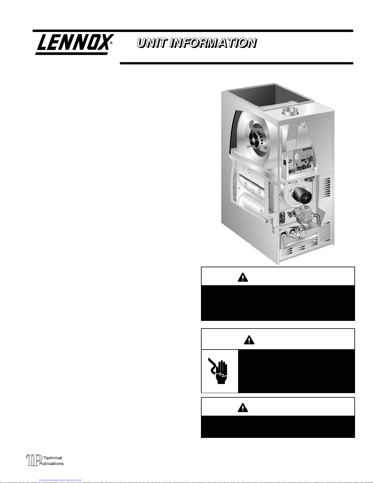
G60DF(X) SERIES UNITS
G60DF series units are mid−efficiency gas furnaces used
for downflow applications only, manufactured with Lennox
Duralok Plus heat exchangers formed of aluminized steel.
Units are available in heating capacities of 44,000 to
132,000 Btuh and cooling applications up to 5 tons. Refer
to Engineering Handbook for proper sizing.
Units are factory equipped for use with natural gas. Kits are
available for conversion to LPG operation. G60DF model
units are equipped with the Lennox two−stage integrated
SureLight control. G60DF units meets the California Nitro-
gen Oxides (NO
x
) Standards and California Seasonal Effi-
ciency requirements. All units use a redundant gas valve to
assure safety shut−off as required by C.S.A.
All specifications in this manual are subject to change. Procedures outlined in this manual are presented as a recommendation only and do not supersede or replace local or
state codes. In the absence of local or state codes, the
guidelines and procedures outlined in this manual (except
where noted) are recommendations only and do not constitute code.
TABLE OF CONTENTS
Specifications Page 2. . . . . . . . . . . . . . . . . . . . . . . . . . . . .
Blower Data Page 4. . . . . . . . . . . . . . . . . . . . . . . . . . . . . .
High Altitude Page 8. . . . . . . . . . . . . . . . . . . . . . . . . . . . . .
Parts Identification Page 9. . . . . . . . . . . . . . . . . . . . . . . . .
I Unit Components Page 10. . . . . . . . . . . . . . . . . . . . . . .
II Installation Page 23. . . . . . . . . . . . . . . . . . . . . . . . . . . .
III Start Up Page 23. . . . . . . . . . . . . . . . . . . . . . . . . . . . . . .
IV Heating System Service Checks Page 24. . . . . . . . .
V Typical Operating Characteristics Page 26. . . . . . . . .
VI Maintenance Page 27. . . . . . . . . . . . . . . . . . . . . . . . . .
VII Wiring and Sequence of Operation Page 30. . . . . .
VIII Field Wiring and Jumper Settings Page 46. . . . . . .
IX Control Board Troubleshooting Page 50. . . . . . . . . .
G60DF−1 MODEL SHOWN
IMPORTANT
Improper installation, adjustment, alteration, service
or maintenance can cause property damage, personal injury or loss of life. Installation and service must
be performed by a qualified installer, service agency
or the gas supplier.
WARNING
Electric shock hazard. Can cause injury
or death. Before attempting to perform
any service or maintenance, turn the
electrical power to unit OFF at disconnect switch(es). Unit may have multiple
power supplies.
WARNING
Sharp edges.
Be careful when servicing unit to avoid sharp edges
which may result in personal injury.
Page 2
Page 2
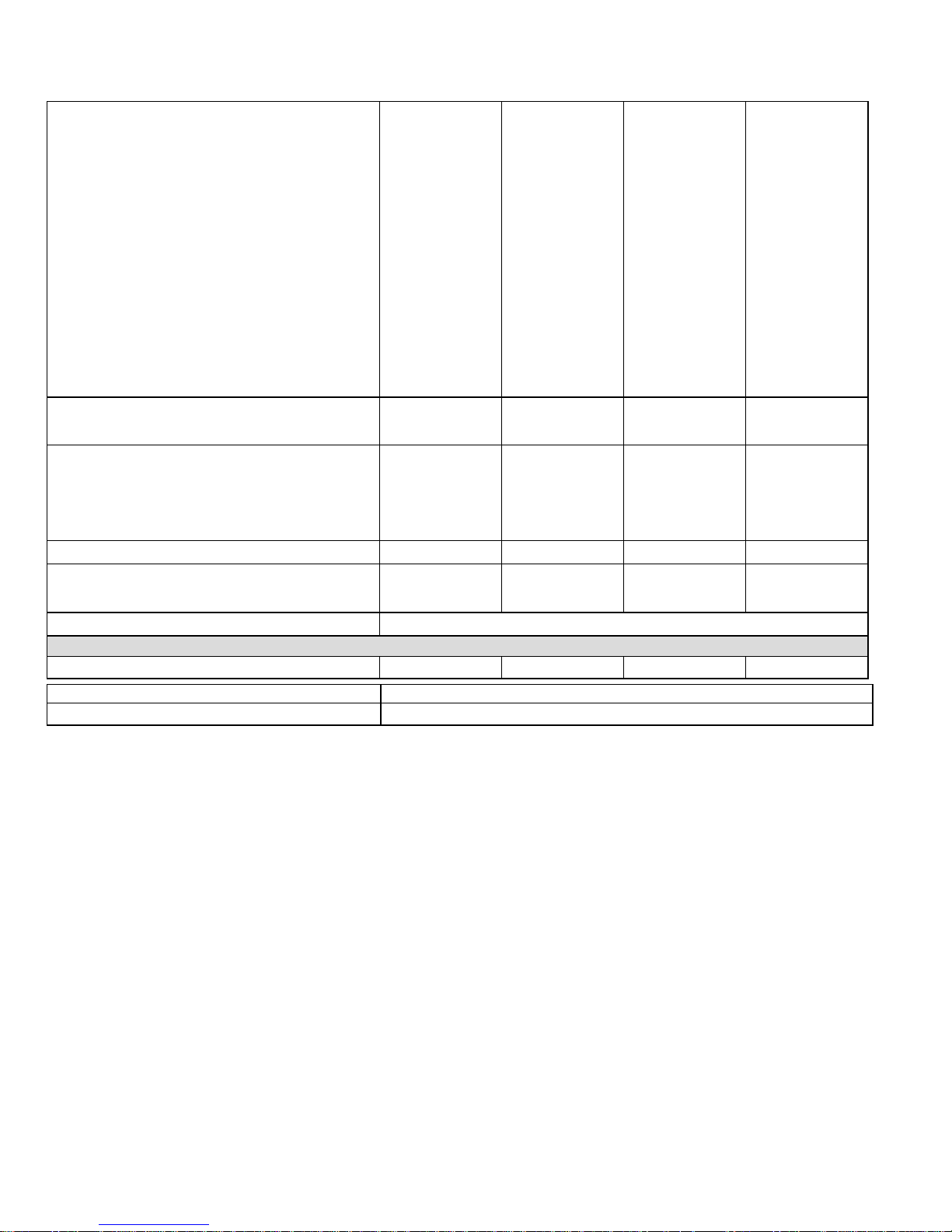
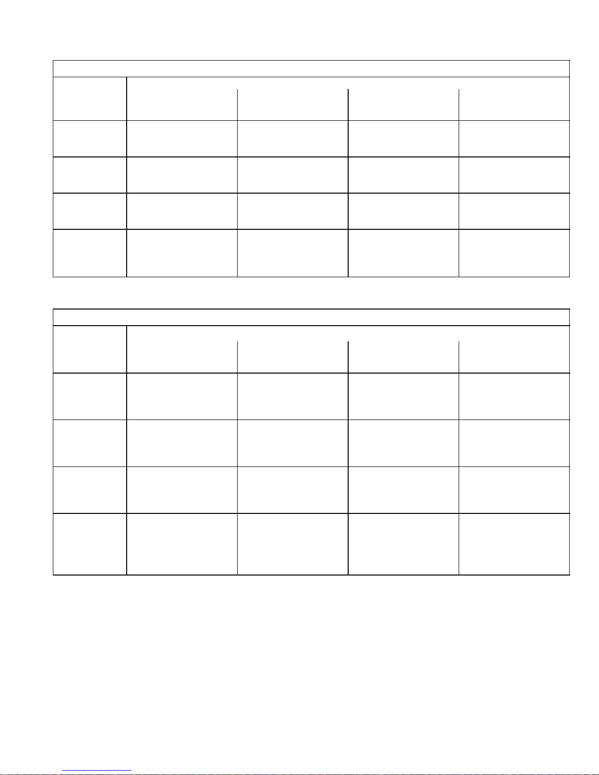
SPECIFICATIONS G60DF(X) Models
Gas
Heating
Performance
ModelNo. G60DF−24A−045 G60DF−36A−070 G60DF−36B−090 G60DF−48C−090
Low NO
x
Model No. G60DF−24A−045X G60DF−36A−070X − − − G60DF−48C−090X
Input− Btuh (kW) low fire 30,000 (8.8) 45,000 (13.2) 60,000 (17.6) 60,000 (17.6)
Output− Btuh (kW) low fire 24,000 (7.0) 36,000 (10.5) 48,000 (14.1) 49,000 (14.4)
Input− Btuh (kW) high fire 44,000 (12.8) 66,000 (19.3) 88,000 (25.8) 88,000 (25.8)
Output− Btuh (kW) high fire 36,000 (10.5) 54,000 (15.8) 72,000 (21.1) 72,000 (21.1)
AFUE 80.0% 80.0% 80.0% 80.0%
California Seasonal Efficiency 73.3% 74.5% 75.0% 74.4%
Highstatic− in.w.g. (Pa) .50 (124) .50 (124) .50 (124) .50 (124)
Temperature rise range − F (C) low fire 15 − 45 (8 − 25) −1, −2, units
20 − 50 (11 − 28)
−4 units 15 − 45
(6 − 25)
−1, −2, units
25 − 55 (14 − 31)
−4 units 20 − 50
(11 − 28)
20 − 50 (11 − 28)
Temperature rise range − F (C) high fire 30 − 60 (17 − 33) 35 − 65 (19 − 36) 45 − 75 (25 − 42) 35 − 65 (19 − 36)
Connections
GaspipesizeIPS− in. (mm) 1/2 (12.7) 1/2 (12.7) 1/2 (12.7) 1/2 (12.7)
Flue connection − in. (mm) round 4 (102) 4 (102) 4 (102) 4 (102)
Indoor
Blower
Wheelnominaldiameter xwidth −in. 10 x 8 10 x 8 10 x 8 10 x 10
mm 254 x 203 254 x 203 254 x 203 254 x 254
Motoroutput − hp (W) 1/5 (149) 1/3 (249) 1/3 (249) 1/2 (373)
Tons(kW) ofadd-oncooling 1.5 − 2 (5.3 − 7.0) 1.5 − 3 (5.3 − 10.6) 1.5 − 3 (5.3 − 10.6) 2 − 4 (7.0 − 14.1)
Shippingweight − 1 package 121 lbs. (55 kg) 132 lbs. (60 kg) 146 lbs. (66 kg) 153 (69)
Matching Coils CR26−18N−F,
CR26−30N−F,
CR26−36N−F
CR26−18N−F,
CR26−30N−F,
CR26−36N−F
CR26−36W−F,
CR26−48N−F
CR26−36W−F,
CR26−48N−F,
CR26−60N−F
Electricalcharacteristics 120 volts − 60 hertz − 1 phase (less than 12 amps)
OPTIONAL ACCESSORIES − MUST BE ORDERED EXTRA
Down−Flow Additive Base − Shipping Weight − lbs. (kg) 11M59 − 9 (4) 11M59 − 9 (4) 11M 60 − 10 (5) 11M 61 − 11 (5)
High Altitude See Page 8
Propane/Natural Gas Kit 0 to 7500 ft. (0 to 2286 m) 59M87
Annual Fuel Utilization Efficiency based on DOE test procedures and according to FTC labeling regulations. Isolated combustion system rating for non-weatherized furnaces.
NOTE − Filters and provisions for mounting are not furnished and must be field provided.
Page 3
Page 3
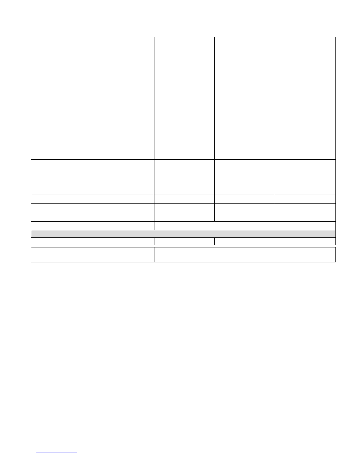
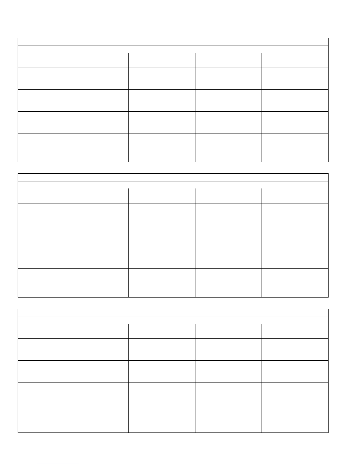
SPECIFICATIONS Cont.
Gas
Heating
Performance
ModelNo. G60DF−48C−110 G60DF−60C−110 G60DF−60D−135
Low NOx Model No. − − − − G60DF−60C−110X − − − −
Input− Btuh (kW) low fire 75,000 (22.0) 75,000 (22.0) 90,000 (26.4)
Output− Btuh (kW) low fire 61,000 (17.9) 61,000 (17.9) 73,000 (21.4)
Input− Btuh (kW) high fire 110,000 (32.2) 110,000 (32.2) 132,000 (38.7)
Output− Btuh (kW) high fire 90,000 (26.4) 91,000 (26.7) 109,000 (31.9)
AFUE 80.0% 80.0% 80.0%
California Seasonal Efficiency 75.4% 74.6% 75.3%
Highstatic− in.w.g. (Pa) .50 (124) .50 (124) .50 (124)
Temperature rise range − F (C) low fire −1, −2 units
25 − 55 (14 − 31)
−4 units 20 − 50 (11 − 28)
20 − 50 (11 − 28) 25 − 55 (14 − 31)
Temperature rise range − F (C) high fire 45 − 75 (25 − 42) 30 − 60 (17 − 33) 40 − 70 (22 − 39)
Connections
GaspipesizeIPS− in. (mm) 1/2 (12.7) 1/2 (12.7) 1/2 (12.7)
Flue connection − in. (mm) round 4 (102) 4 (102) 4 (102)
Indoor
Blower
Wheelnominaldiameter xwidth −in. 10 x 10 11−1/2 x 10 11−1/2 x 10
mm 254 x 254 292 x 254 292 x 254
Motoroutput − hp (W) 1/2 (373) 3/4 (560) 3/4 (560)
Tons(kW) ofadd-oncooling 2 − 4 (7.0 − 14.1) 4 − 5 (14.1 − 17.6) 4 − 5 (14.1 − 17.6)
Shippingweight − 1 package 169 lbs. (77 kg) 169 lbs. (77 kg) 192 lbs. (87 kg)
Matching Coils CR26−36W−F,
CR26−48N−F,
CR26−60N−F
CR26−48N−F,
CR26−60N−F
CR26−48W−F,
CR26−60W−F
Electricalcharacteristics 120 volts − 60 hertz − 1 phase (less than 12 amps)
OPTIONAL ACCESSORIES − MUST BE ORDERED EXTRA
Down−Flow Additive Base − Shipping Weight − lbs. (kg) 11M 61 − 11 (5) 11M6 1 − 11 (5) 11M6 2 − 13 (6)
High Altitude See Page 8
Propane/Natural Gas Kit 0 to 7500 ft. (0 to 2286 m) 59M87
Annual Fuel Utilization Efficiency based on DOE test procedures and according to FTC labeling regulations. Isolated combustion system rating for non-weatherized furnaces.
NOTE − Filters and provisions for mounting are not furnished and must be field provided.
Page 4
Page 4
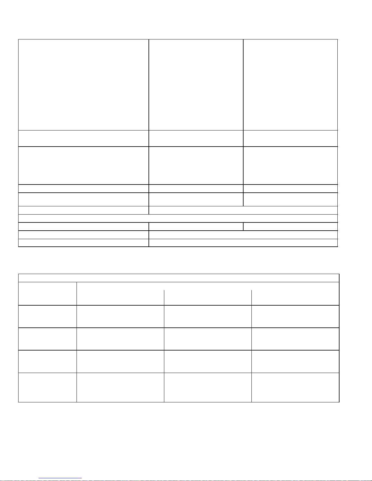
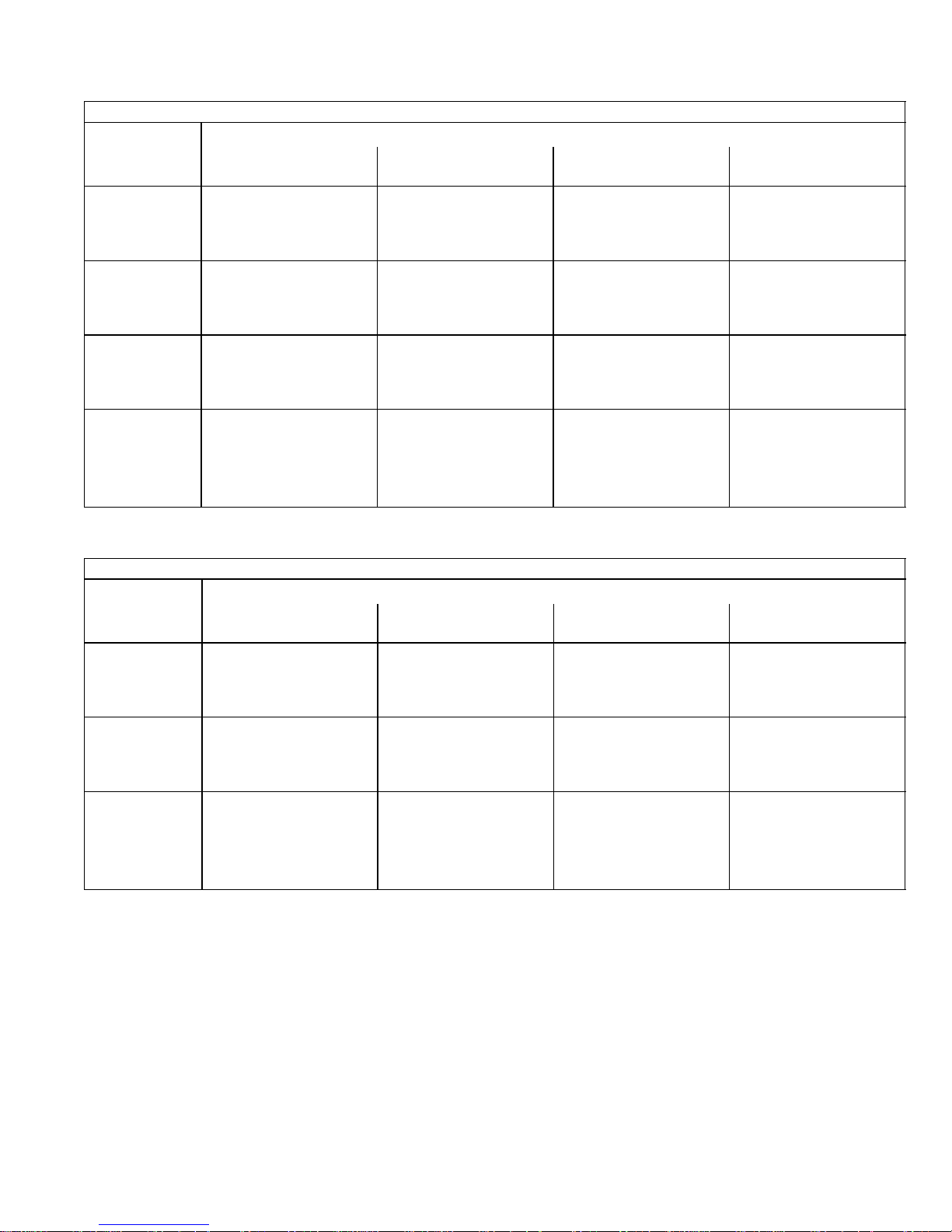
SPECIFICATIONS Cont.
Gas
Heating
Performance
ModelNo. G60DF−60C−110 G60DF−60D−135
Low NOx Model No. G60DF−60C−110X − − − −
Input− Btuh (kW) low fire 75,000 (22.0) 90,000 (26.4)
Output− Btuh (kW) low fire 61,000 (17.9) 73,000 (21.4)
Input− Btuh (kW) high fire 110,000 (32.2) 132,000 (38.7)
Output− Btuh (kW) high fire 91,000 (26.7) 109,000 (31.9)
AFUE 80.0% 80.0%
California Seasonal Efficiency 74.6% 75.3%
Highstatic− in.w.g. (Pa) .50 (124) .50 (124)
Temperature rise range − F (C) low fire 20 − 50 (11 − 28) 25 − 55 (14 − 31)
Temperature rise range − F (C) high fire 30 − 60 (17 − 33) 40 − 70 (22 − 39)
Connections
GaspipesizeIPS− in. (mm) 1/2 (12.7) 1/2 (12.7)
Flue connection − in. (mm) round 4 (102) 4 (102)
Indoor
Blower
Wheelnominaldiameter xwidth −in. 11−1/2 x 10 11−1/2 x 10
mm 292 x 254 292 x 254
Motoroutput − hp (W)
1 (746)
−1, −2 models 3/4 (560)
1 (746)
−1, −2 models 3/4 (560)
Tons(kW) ofadd-oncooling 4 − 5 (14.1 − 17.6) 4 − 5 (14.1 − 17.6)
Shippingweight − 1 package 172 lbs. (78 kg) 195 lbs. (88 kg)
Matching Coils CR26−48N−F,
CR26−60N−F
CR26−48W−F,
CR26−60W−F
Electricalcharacteristics 120 volts − 60 hertz − 1 phase (less than 12 amps)
OPTIONAL ACCESSORIES − MUST BE ORDERED EXTRA
Down−Flow Additive Base − Shipping Weight − lbs. (kg) 11M 61 − 11 (5) 11 M62 − 13 (6)
High Altitude See Page 8
Propane/Natural Gas Kit 0 to 7500ft (0 − 2286m) 59M87
Annual Fuel Utilization Efficiency based on DOE test procedures and according to FTC labeling regulations. Isolated combustion system rating for non-weatherized furnaces.
NOTE − Filters and provisions for mounting are not furnished and must be field provided.
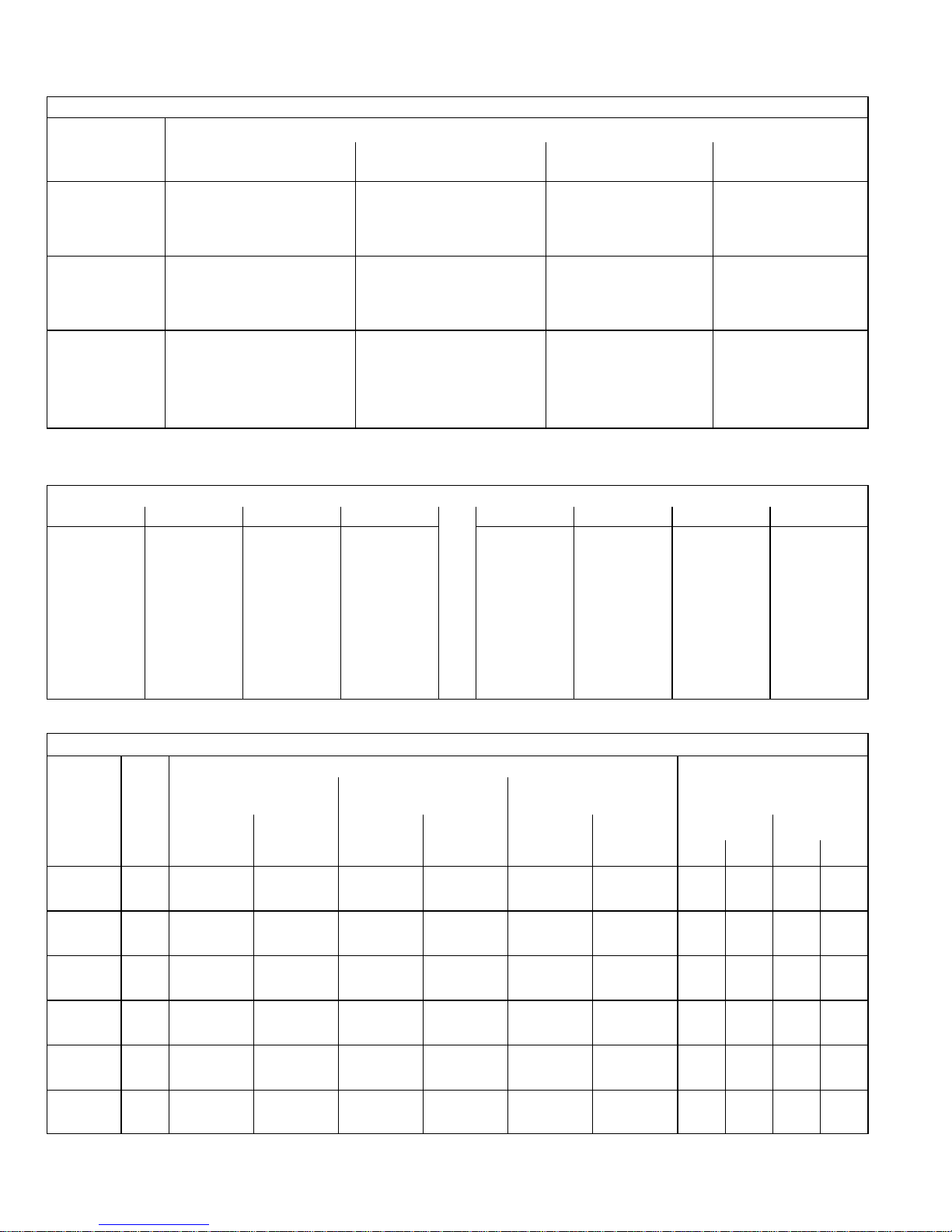
BLOWER DATA
G60DF−24A−045 PERFORMANCE
External Static
Pressure
Air Volume / Watts at Different Blower Speeds
High Medium Low
in. w.g. Pa cfm L/s Watts cfm L/s Watts cfm L/s Watts
0.00 0 1202 565 417 1058 500 367 828 390 278
0.05 12 1185 560 410 1041 490 360 819 385 274
0.10 25 1167 550 402 1024 482 353 809 380 270
0.15 37 1147 540 396 1008 475 346 793 375 265
0.20 50 1127 530 390 991 470 338 776 365 260
0.25 62 1104 520 382 979 460 335 764 360 257
0.30 75 1081 510 374 966 455 331 752 355 254
0.40 100 1018 480 357 922 435 319 712 335 244
0.50 125 960 455 342 873 410 306 651 305 234
0.60 150 901 425 330 811 385 290 618 290 231
0.70 175 815 385 313 691 325 272 564 265 221
0.80 200 685 325 289 619 290 259 465 220 203
0.90 225 558 265 271 510 240 238 395 185 190
NOTE − All air data is measured external to unit with 1 in. (25 mm) cleanable filter (not furnished − field provided) in place. Also see Filter Air Resistance table.
Page 5
Page 5
BLOWER DATA Cont.
G60DF−36A−070 PERFORMANCE
External Static
Pressure
Air Volume / Watts at Different Blower Speeds
High Medium−High Medium−Low Low
in. w.g. Pa cfm L/s Watts cfm L/s Watts cfm L/s Watts cfm L/s Watts
0.00 0 1475 695 616 1343 635 554 1151 545 495 989 465 415
0.05 12 1449 685 606 1321 625 543 1139 540 481 983 465 407
0.10 25 1423 670 595 1298 615 532 1127 530 466 976 460 398
0.15 37 1397 660 585 1276 600 521 111 5 525 452 970 460 390
0.20 50 1371 645 574 1253 590 510 1103 520 437 963 455 381
0.25 62 1345 635 563 1228 580 494 1090 515 428 953 450 371
0.30 75 1318 620 552 1203 570 478 1077 510 418 943 445 360
0.40 100 1249 590 528 1151 545 455 1039 490 395 918 435 346
0.50 125 1200 565 508 1094 515 432 998 470 374 882 415 331
0.60 150 1112 525 475 1033 490 409 951 450 354 831 390 313
0.70 175 1032 485 455 968 455 390 856 405 338 722 340 280
0.80 200 959 455 434 876 415 359 737 350 299 666 315 266
0.90 225 770 365 389 715 335 321 667 315 278 591 280 244
NOTE − All air data is measured external to unit with 1 in. (25 mm) cleanable filter (not furnished − field provided) in place. Also see Filter Air Resistance table.
G60DF−36B−090 PERFORMANCE
External Static
Pressure
Air Volume / Watts at Different Blower Speeds
High Medium−High Medium−Low Low
in. w.g. Pa cfm L/s Watts cfm L/s Watts cfm L/s Watts cfm L/s Watts
0.00 0 1598 755 608 1408 665 526 1166 550 436 963 455 355
0.05 12 1579 745 599 1398 660 518 1164 550 428 966 455 351
0.10 25 1559 735 589 1388 655 509 1161 550 420 968 455 346
0.15 37 1528 720 573 1369 645 497 1156 545 413 966 455 341
0.20 50 1497 705 556 1350 635 485 1150 545 406 964 455 335
0.25 62 1465 690 544 1326 625 473 1137 535 398 955 450 329
0.30 75 1432 675 532 1301 615 460 1124 530 389 945 445 323
0.40 100 1370 645 509 1248 590 438 1093 515 373 933 440 313
0.50 125 1294 610 482 1198 565 420 1055 500 355 902 425 302
0.60 150 1213 575 456 1141 540 397 1012 480 343 862 405 285
0.70 175 1139 540 437 1054 495 371 917 435 313 802 380 272
0.80 200 1002 475 401 948 445 342 850 400 295 728 345 251
0.90 225 901 425 374 822 390 313 740 350 272 − − − − − − − − −
NOTE − All air data is measured external to unit with 1 in. (25 mm) cleanable filter (not furnished − field provided) in place. Also see Filter Air Resistance table.
Page 6
Page 6
BLOWER DATA Cont.
G60DF−48C−090 PERFORMANCE
External Static
Pressure
Air Volume / Watts at Different Blower Speeds
High Medium−High Medium−Low Low
in. w.g. Pa cfm L/s Watts cfm L/s Watts cfm L/s Watts cfm L/s Watts
0.00 0 2039 960 749 1852 875 657 1595 755 562 1325 625 466
0.05 12 1998 945 727 1826 860 638 1576 745 547 1338 632 460
0.10 25 1956 925 704 1800 850 619 1556 735 532 1351 640 453
0.15 37 1921 905 692 1770 835 602 1541 725 518 1340 630 441
0.20 50 1885 890 679 1739 820 585 1526 720 503 1329 625 428
0.25 62 1844 870 662 1701 805 568 1502 710 488 1301 615 414
0.30 75 1802 850 645 1663 785 551 1477 695 473 1272 600 399
0.40 100 1693 800 606 1583 745 517 1415 670 448 1226 580 378
0.50 125 1600 755 570 1491 705 485 1334 630 414 1170 550 360
0.60 150 1494 705 540 1406 665 457 1248 590 389 111 0 525 337
0.70 175 1378 650 509 1300 615 426 1166 550 367 1026 485 316
0.80 200 1248 590 478 1161 550 390 1027 485 331 − − − − − − − − −
0.90 225 1097 520 439 1028 485 360 925 435 307 − − − − − − − − −
NOTE − All air data is measured external to unit with 1 in. (25 mm) cleanable filter (not furnished − field provided) in place. Also see Filter Air Resistance table.
G60DF−48C−110 PERFORMANCE
External Static
Pressure
Air Volume / Watts at Different Blower Speeds
High Medium−High Medium−Low Low
in. w.g. Pa cfm L/s Watts cfm L/s Watts cfm L/s Watts cfm L/s Watts
0.00 0 2034 960 846 1790 845 712 1508 710 595 1226 580 477
0.05 12 2001 945 825 1761 830 694 1493 705 581 1224 580 470
0.10 25 1968 930 803 1731 815 675 1477 695 567 1222 575 463
0.15 37 1924 910 781 1708 805 657 1470 695 555 1219 575 455
0.20 50 1879 885 758 1685 795 638 1463 690 542 1216 575 447
0.25 62 1837 865 736 1654 780 618 1442 680 528 1201 565 437
0.30 75 1794 845 714 1623 765 597 1420 670 514 1186 560 427
0.40 100 1681 795 669 1548 730 564 1361 640 483 1134 535 400
0.50 125 1622 765 630 1445 680 524 1280 605 447 1065 505 371
0.60 150 1447 685 592 1312 620 479 1165 550 404 1000 470 343
0.70 175 1289 610 545 1178 555 434 1056 500 369 907 430 319
0.80 200 1157 545 502 1067 505 406 956 450 348 816 385 296
0.90 225 1012 480 472 931 440 372 840 395 320 690 325 265
NOTE − All air data is measured external to unit with 1 in. (25 mm) cleanable filter (not furnished − field provided) in place. Also see Filter Air Resistance table.
G60DF−60C−110 with 3/4 hp PERFORMANCE
External Static
Pressure
Air Volume / Watts at Different Blower Speeds
High Medium−High Medium−Low Low
in. w.g. Pa cfm L/s Watts cfm L/s Watts cfm L/s Watts cfm L/s Watts
.00 0 2450 1155 1170 2355 111 0 1005 2145 1015 840 1845 870 705
.05 10 2430 1150 1165 2340 1105 995 2130 1005 835 1840 870 695
.10 25 2380 1120 1145 2315 1090 985 2105 995 825 1830 865 690
.15 35 2350 1110 1135 2260 1065 965 2085 985 815 1815 855 680
.20 50 2300 1085 1115 2235 1055 955 2060 975 805 1805 850 675
.25 60 2270 1070 1105 2205 1040 945 2015 950 785 1780 840 665
.30 75 2245 1060 1100 2150 1015 925 1995 940 775 1770 835 655
.40 100 2135 1010 1060 2070 975 895 1925 910 750 1730 815 640
.50 125 2055 970 1035 1990 940 870 1855 875 725 1695 800 625
.60 150 1975 930 1010 1910 900 845 1785 845 705 1650 775 605
.70 175 1870 880 980 1830 865 820 1695 800 680 1575 745 585
.80 200 1760 830 950 1720 815 795 1605 755 655 1505 710 570
.90 225 1625 765 915 1560 735 755 1515 715 640 1435 675 555
NOTE − All air data is measured external to unit with 1 in. (25 mm) cleanable filter (not furnished − field provided) in place. Also see Filter Air Resistance table.
Page 7
Page 7
BLOWER DATA Cont.
G60DF−60D−135 with 3/4 hp PERFORMANCE
External Static
Pressure
Air Volume / Watts at Different Blower Speeds
High Medium−High Medium−Low Low
in. w.g. Pa cfm L/s Watts cfm L/s Watts cfm L/s Watts cfm L/s Watts
0.00 0 2845 1345 1143 2692 1270 961 2451 1155 818 2054 970 686
0.05 12 2774 1310 1128 2628 1240 948 2354 1110 809 2022 955 680
0.10 25 2702 1275 1112 2564 1210 935 2256 1065 799 1989 940 674
0.15 37 2629 1240 1095 2494 1175 918 2203 1040 784 1933 910 666
0.20 50 2556 1205 1077 2424 1145 901 2150 1015 769 1877 885 657
0.25 62 2471 1165 1061 2309 1090 890 2089 985 759 1835 865 649
0.30 75 2385 1125 1045 2194 1035 878 2028 955 749 1792 845 640
0.40 100 2184 1030 1022 2066 975 851 1900 895 727 1697 800 626
0.50 125 2019 955 990 1917 905 830 1779 840 707 1584 750 602
0.60 150 1865 880 957 1760 830 796 1630 770 676 1491 705 583
0.70 175 1697 800 927 1592 750 768 1475 695 656 1364 645 557
0.80 200 1513 715 897 1485 700 740 1378 650 627 1266 600 538
0.90 225 1385 655 863 1305 615 712 1206 570 598 1120 530 516
NOTE − All air data is measured external to unit with 1 in. (25 mm) cleanable filter (not furnished − field provided) in place. Also see Filter Air Resistance table.
G60DF−60C−110 with 1 hp PERFORMANCE
External Static
Pressure
Air Volume / Watts at Different Blower Speeds
High Medium−High Medium−Low Low
in. w.g. Pa cfm L/s Watts cfm L/s Watts cfm L/s Watts cfm L/s Watts
.00 0 2475 1170 1276 2280 1075 987 1995 940 845 1690 795 698
.10 25 2390 1125 1248 2235 1055 955 1990 940 829 1675 790 690
.20 50 2330 1100 1223 2180 1030 945 1975 930 809 1665 785 675
.30 75 2245 1060 1192 2125 1000 911 1940 915 786 1660 785 657
.40 100 2175 1025 1187 2050 965 880 1895 895 757 1650 780 636
.50 125 2085 985 1145 1970 930 849 1835 870 734 1625 765 619
.60 150 2020 955 1129 1880 885 815 1750 825 695 1580 745 599
.70 175 1920 905 1094 1775 835 785 1660 785 669 1525 720 579
.80 200 1785 840 1052 1685 795 762 1585 745 645 1440 680 556
.90 225 1670 790 1020 1600 755 741 1520 715 633 1370 645 538
NOTE − All air data is measured external to unit with 1 in. (25 mm) cleanable filter (not furnished − field provided) in place. Also see Filter Air Resistance table.
Page 8
Page 8
BLOWER DATA Cont.
G60DF−60D−135 with 1 hp PERFORMANCE
External Static
Pressure
Air Volume / Watts at Different Blower Speeds
High Medium−High Medium−Low Low
in. w.g. Pa cfm L/s Watts cfm L/s Watts cfm L/s Watts cfm L/s Watts
.00 0 2660 1255 1379 2325 1095 1059 1960 925 864 1655 780 684
.10 25 2560 1210 1353 2310 1090 1030 1945 915 840 1640 775 667
.20 50 2490 1175 1325 2280 1075 1000 1940 915 824 1630 770 661
.30 75 2415 1140 1293 2225 1050 972 1930 910 801 1625 765 649
.40 100 2345 1105 1264 2170 1025 941 1910 900 779 1620 760 638
.50 125 2265 1070 1235 2115 1000 918 1870 880 754 1615 760 624
.60 150 2165 1020 1199 2020 955 880 1830 865 733 1585 745 604
.70 175 2050 965 1160 1940 915 854 1755 830 705 1570 740 604
.80 200 1955 920 1112 1865 880 828 1680 790 683 1515 715 584
.90 225 1865 880 1096 1760 830 797 1605 755 656 1465 690 567
NOTE − All air data is measured external to unit with 1 in. (25 mm) cleanable filter (not furnished − field provided) in place. Also see Filter Air Resistance table.
FILTER AIR RESISTANCE
cfm L/s in. w.g. Pa cfm L/s in. w.g. Pa
0 0 0.00 0 1400 660 0.15 35
200 95 0.01 0 1600 755 0.19 45
400 190 0.03 5 1800 850 0.23 55
600 285 0.04 10 2000 945 0.27 65
800 380 0.06 15 2200 1040 0.33 80
1000 470 0.09 20 2400 1130 0.38 95
1200 565 0.12 30 2600 1225 0.44 11 0
Data is for 1 inch (25 mm) cleanable filter (field provided).
HIGH ALTITUDE / MANIFOLD PRESSURE INFORMATION
Model
Input
Size
Gas
Altitude
Manifold Pressure
at all altitudes
0 − 4500 ft.
(0 − 1372 m)
4,501 − 7500 ft.
(1373 − 2286 m)
7501−10,000 ft.
(2286 − 3048 m)
Required
Conversion
Kit
Pressure
Switch
Required
Conversion
Kit
1
Pressure
Switch
Required
Conversion
Kit
1
Pressure
Switch
Low Fire High Fire
in. w.g. kPa in. w.g. kPa
045/070−1 to
−6
Nat. no change
no change
no change N/A 59M16 18M64 1.7 0.42 3.5 0.87
LPG 59M13 59M13 N/A 59M14 18M64 4.9 1.22 10.0 2.5
045/070−7
and later
Nat. no change
no change
no change N/A 59M17 18M64 1.7 0.42 3.5 0.87
LPG 59M13 59M13 N/A 59M14 18M64 4.9 1.22 10.0 2.5
090−1 to −6
Nat. no change
no change
no change 18M61 59M16 18M64 1.7 0.42 3.5 0.87
LPG 59M13 59M13 18M61 59M14 18M64 4.9 1.22 10.0 2.5
090−7 and
later
Nat. no change
no change
no change 18M61 59M17 18M64 1.7 0.42 3.5 0.87
LPG 59M13 59M13 18M61 59M14 18M64 4.9 1.22 10.0 2.5
110/135−1 to
−6
Nat. no change
no change
no change 18M63 59M16 18M61 1.7 0.42 3.5 0.87
LPG 59M13 59M13 18M63 59M14 18M61 4.9 1.22 10.0 2.5
110/135−7
and later
Nat. no change
no change
no change 18M63 59M17 18M61 1.7 0.42 3.5 0.87
LPG 59M13 59M13 18M63 59M14 18M61 4.9 1.22 10.0 2.5
Pressure switch is factory set. No adjustment necessary. All models use the factory installed pressure switch from 0−4500 feet (0−1372 m).
1 − Conversion requires 2 pressure switches
Page 9
Page 9
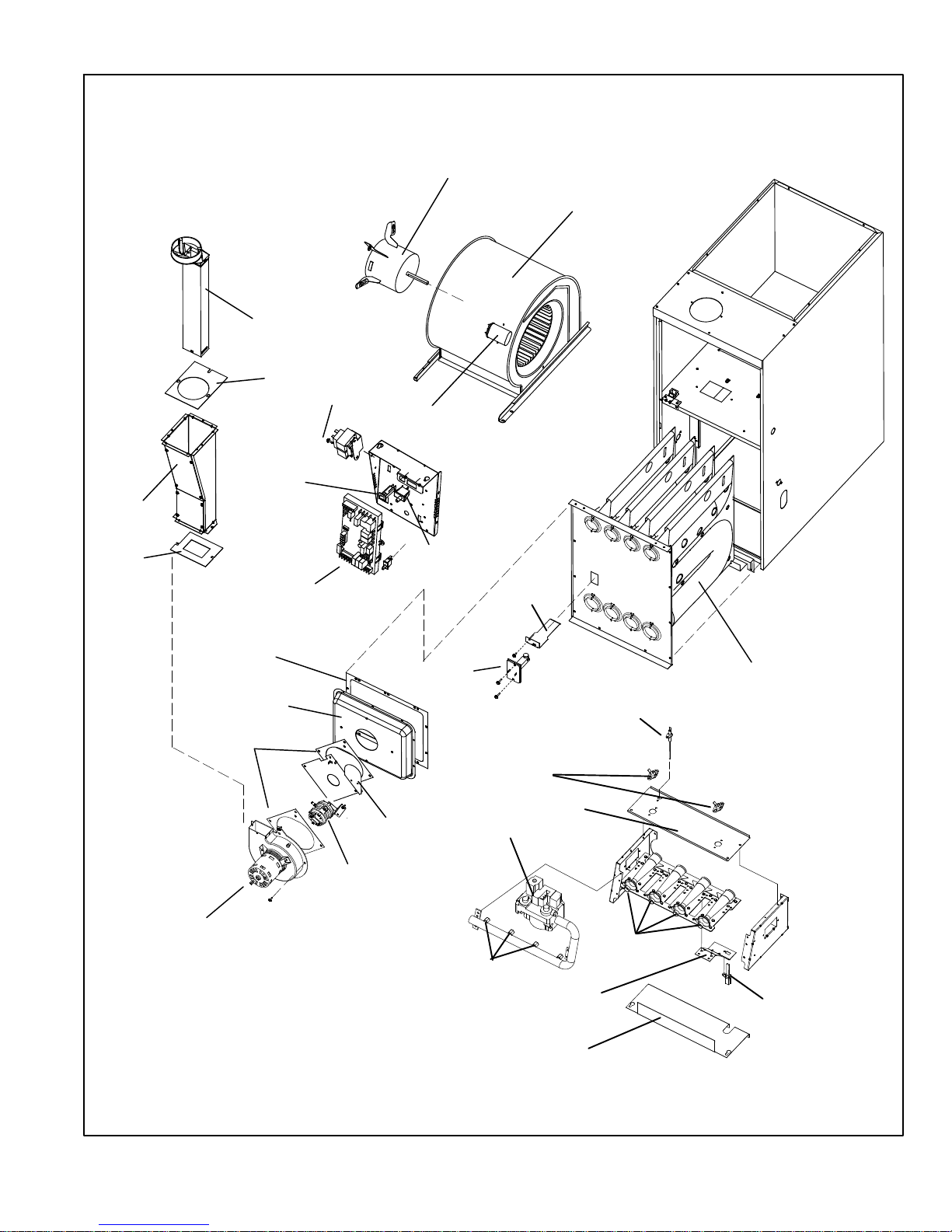
FIGURE 1
Blower Assembly
Blower Motor
Capacitor
Internal Flue Pipe
Assembly
Flue Box Gasket
Flue Collector Box
Gasket
Combustion Air Inducer
Gasket
Primary
Limit
Heat Exchanger
Combustion Air
Prove Switch
Assembly
(Two Switches)
Combustion
Air Orifice
Transformer
SureLight
®
Two−Stage
Integrated Control Board
Flue
Chase
Gasket
Door
Interlock Switch
Limit
Shield
Circuit Breaker
Flame Sensor
Gas Valve
Burners
Ignitor
Flame Rollout Switches*
Flame Rollout Bracket
Gas Orifices
Ignitor Bracket
Burner Bottom Shield
*Flame rollout switches are
located on brackets on the
inner sides.
PARTS ARRANGEMENT
NOTE − G60DF−1, −2 and −3 model units are
equipped with a fully covered burner box.
Page 10
Page 10
I−UNIT COMPONENTS
Unit components are shown in figure 1. The gas valve,
combustion air inducer and burners can be accessed by removing the burner access panel. Electrical components
are in the control box (figure 2) found in the blower section.
CAUTION
Electrostatic discharge can affect electronic
components. Take precautions during furnace
installation and service to protect the furnace’s
electronic controls. Precautions will help to avoid
control exposure to electrostatic discharge by
putting the furnace, the control and the technician at the same electrostatic potential. Neutralize electrostatic charge by touching hand and all
tools on an unpainted unit surface, such as the
gas valve or blower deck, before performing any
service procedure.
ELECTROSTATIC DISCHARGE (ESD)
Precautions and Procedures
1. Control Transformer (T1)
A transformer located in the control box provides power to
the low voltage section of the unit. Transformers on all
models are rated 40VA with a 120V primary and a 24V secondary.
2. Door Interlock Switch (S51)
A door interlock switch rated 14A at 125VAC is wired in series with line voltage. When the blower door is removed the
unit will shut down.
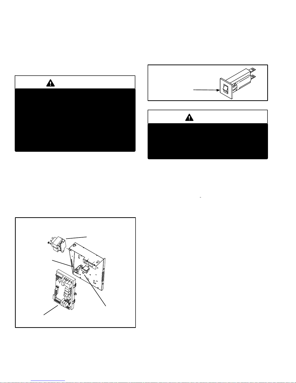
FIGURE 2
CONTROL BOX G60DF
Door Interlock Switch
Two−Stage Integrated
Control Board
Control Transformer
Circuit Breaker
3. Circuit Breaker (CB8)
A 24V circuit breaker is also located in the control box.
The switch provides overcurrent protection to the transformer (T1). The breaker is rated 3A at 32V. If the current
exceeds this limit the breaker will trip and all unit operation will shutdown. The breaker can be manually reset
by pressing the button on the face. See figure 3.
FIGURE 3
CIRCUIT BREAKER CB8
PRESS TO RESET
WARNING
Shock hazard.
Disconnect power before servicing. Integrated
Control Board is not field repairable. If control is
inoperable, simply replace entire control.
Can cause injury or death. Unsafe operation will
result if repair is attempted.
4. Integrated Control Board(A92)
SureLight
®
Board 18M34
All G60DF units are equipped with the Lennox two−stage
integrated SureLight control board. The system consists
of a ignition control board (figure 4 with control terminal
designations in tables 3,
4 and 5) and ignitor (figure 8).
The board and ignitor work in combination to ensure furnace ignition and ignitor durability. The board controls all
major furnace operations. The board features two LED
lights, DS1 and DS2 for troubleshooting. The board also
has two accessory terminals rated at (1) one amp each.
See table 6 for troubleshooting diagnostic codes.
Electronic Ignition
At the beginning of each heat cycle, SureLight control monitors the first stage and second stage combustion air inducer prove switch. The control will not begin the heating cycle
if the first stage prove switch is closed (by−passed). Likewise the control will not begin the second stage heating
cycle if the second stage prove switch is closed and will allow first stage heat only. However if the second stage prove
switch closes during the first stage pre−purge, the control
will still respond to second stage heat. Once the first stage
prove switch is determined to be open, the combustion air
inducer is energized on low (first stage) heat speed. When
the differential in the prove switch is great enough, the
prove switch closes and a 15−second pre−purge begins. If
the switch is not proven within 2−1/2 minutes, the control
goes into Watchguard−Pressure Switch mode for a 5−minute re−set period.
Page 11
Page 11
After the 15−second pre−purge period, the SureLight ignitor
warms up for 20 seconds after which the gas valve opens
for a 4−second trial for ignition. The ignitor energizes during
the trial until flame is sensed. If ignition is not proved during
the 4−second period, the control will try four more times with
an inter purge and warm−up time between trials of 35 seconds. After a total of five trials for ignition (including the initial trial), the control goes into Watchguard−Flame Failure
mode. After a 60−minute reset period, the control will begin
the ignition sequence again.
The SureLight control board has an added feature that prolongs the life of the ignitor. After a successful ignition, the
SureLight control utilizes less power to energize the ignitor
on successive calls for heat. The control continues to ramp
down the voltage to the ignitor until it finds the lowest
amount of power that will provide a successful ignition. This
amount of power is used for 255 cycles. On the 256th call
for heat, the control will again ramp down until the lowest
power is determined and the cycle begins again.
Two Stage Operation / Thermostat Selection Jumper
The control can be utilized in two modes: SINGLE−STAGE
thermostat or TWO−STAGE thermostat. The thermostat
selection jumper E20, located just below dip switches 1
through 4 (figure 4), must be positioned for the particular
application. The jumper is factory set on TWO" for use
with a two−stage thermostat with two stage heat. Re−position jumper to SINGLE" for use with a single stage thermostat with two stage heat.
While in the single−stage thermostat mode (single jumper
setting), the burners will always fire on first−stage heat. The
combustion air inducer will operate on low speed and indoor blower will operate on low heat speed. After a field selectable 10 or 15 minute delay (dip switch 3), the unit will
switch to second stage heat. While in the two−stage thermostat mode (two jumper setting) the burners will fire on
first−stage heat. The combustion air inducer will operate on
low speed and indoor blower will operate on low heat
speed. The unit will switch to second−stage heat on call
from the indoor thermostat. If there is a simultaneous call
for W1 and W2 (first and second stage heat) the unit will fire
on first stage heat and will switch to second stage heat after
30 seconds of operation. See Sequence of Operation flow
charts in the back of this manual for more detail.
Dip Switch Settings
Dip Switches 1 and 2 − Heating Fan off Delay − The fan on
time of 45 seconds is not adjustable. Fan off time (time that
the blower operates after the heat demand has been satisfied) can be adjusted by flipping the dip switches 1 and 2
located on the SureLight integrated control. The unit is
shipped with a factory fan off setting of 90 seconds. Fan off
time will affect comfort and is adjustable to satisfy individual
applications.
For customized comfort, monitor the supply air temperature once the heat demand is satisfied. Note the supply air
temperature at the instant the blower is de−energized. Adjust the fan−off delay to achieve a supply air temperature
between 90° − 110° at the instant the blower is de−energized. (Longer delay times allow for lower air temperature,
shorter delay times allow for higher air temperature). See
table 1 for dip switch settings.
TABLE 1
Heating Fan Off Delay
Delay (Seconds)
Switch 1 Switch 2
60 Off Off
90 Off On
120 On Off
180 On On
Switch 3 − Second Stage Delay (Used with Single−Stage
Thermostat Only) −− This switch is used to determine the
second stage on delay when a single−stage thermostat is
being used. The switch is factory−set in the ON position,
which provides a 10−minute delay before second−stage
heat is initiated. If the switch is toggled to the OFF position,
it will provide a 15−minute delay before second−stage heat
is initiated. This switch is only activated when the thermostat selector jumper is positioned for SINGLE−stage thermostat use.
Switch 4 − Cooling Fan off Delay − The fan on delay time
of 2 seconds is not adjustable. Fan off time (time that the
blower operates after the cool demand has been satisfied)
can be adjusted by flipping dip switch 4. The unit is shipped
with a factory fan off setting of 45 seconds. Fan off time will
affect comfort and is adjustable to satisfy individual applications. See table 2 for cool fan off time settings.
TABLE 2
Cooling Fan Off Delay
Delay (Seconds)
Switch 4
2 Off
45 On
Diagnostic LED’s (DS1 and DS2)
Two diagnostic LED’S are located on the two−stage integrated control board. See figure 4. These light flashes correspond with the codes detailed in table 6.
Factory Installed Jumper Y1 to Y2
A factory−installed jumper from Y1 to Y2 terminals on the
integrated control board terminal strip must be clipped for
two−stage cooling.
Page 12
Page 12
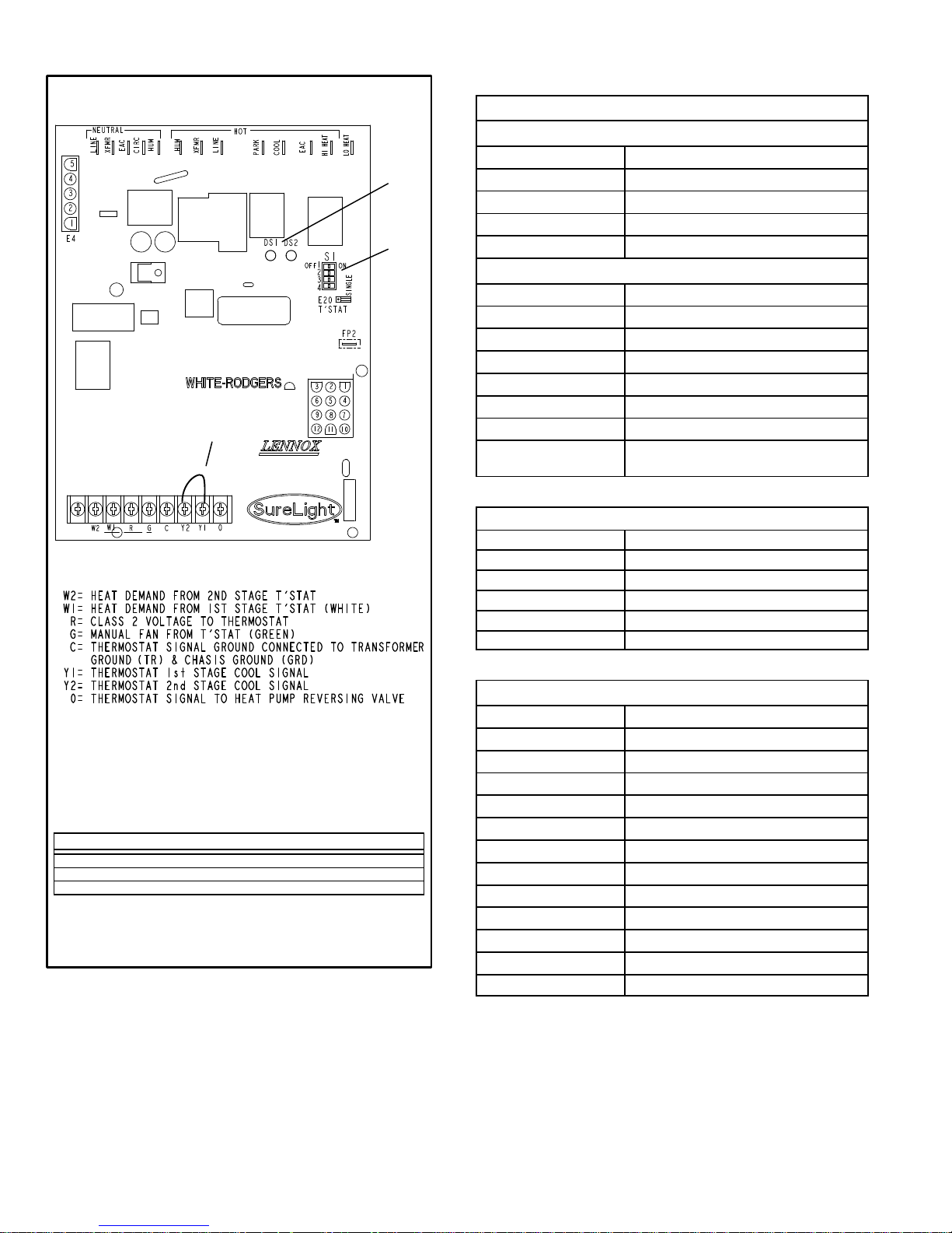
TWO−STAGE CONTROL BOARD 18M34
FIGURE 4
THERMOSTAT CONNECTIONS (TB1)
DIP
SWITCHES
1 − 4
LEDs
FACTORY−
INSTALLED
JUMPER
DIP SWITCH(ES) FUNCTION
1 and 2 Blower Off Delay (Heating Mode)
3 Second Stage ON Delay (Single−stage t’stat)
4 Blower Off Delay (Cooling Mode)
SENSOR
TABLE 3
Integrated Control Board Terminals
120VAC Neutral
LINE Line
XFMR Transformer
EAC Electronic Air Cleaner
CIRC Indoor Blower
HUM Humidifier
120VAC Line
HUM Humidifier
XMFR Transformer
LINE Line
PARK For Unused Leads
COOL Cooling Speed
EAC Electronic Air Cleaner
HI HEAT High Heat Speed
LO HEAT Low Heat, Low Cool and Continuous Fan
Speed
TABLE 4
Integrated Control Board 5 Pin Terminal
PIN # Function
1 Ignitor
2 Combustion Air Inducer High Speed
3 Combustion Air Inducer Low Speed
4 Combustion Air Inducer Neutral
5 Ignitor Neutral
TABLE 5
Integrated Control Board 12Pin Terminal
PIN # Function
1 Gas Valve 2nd Stage (High Fire)
2 Second Stage Prove Switch
3 Not Used
4 Ground
5 24V Hot
6 Primary Limit In
7 Gas Valve 1st stage (Low Fire)
8 Gas Valve Common
9 24V Neutral
10 Ground
11 Primary Limit Out
12 1st Stage Prove Switch
Page 13
Page 13
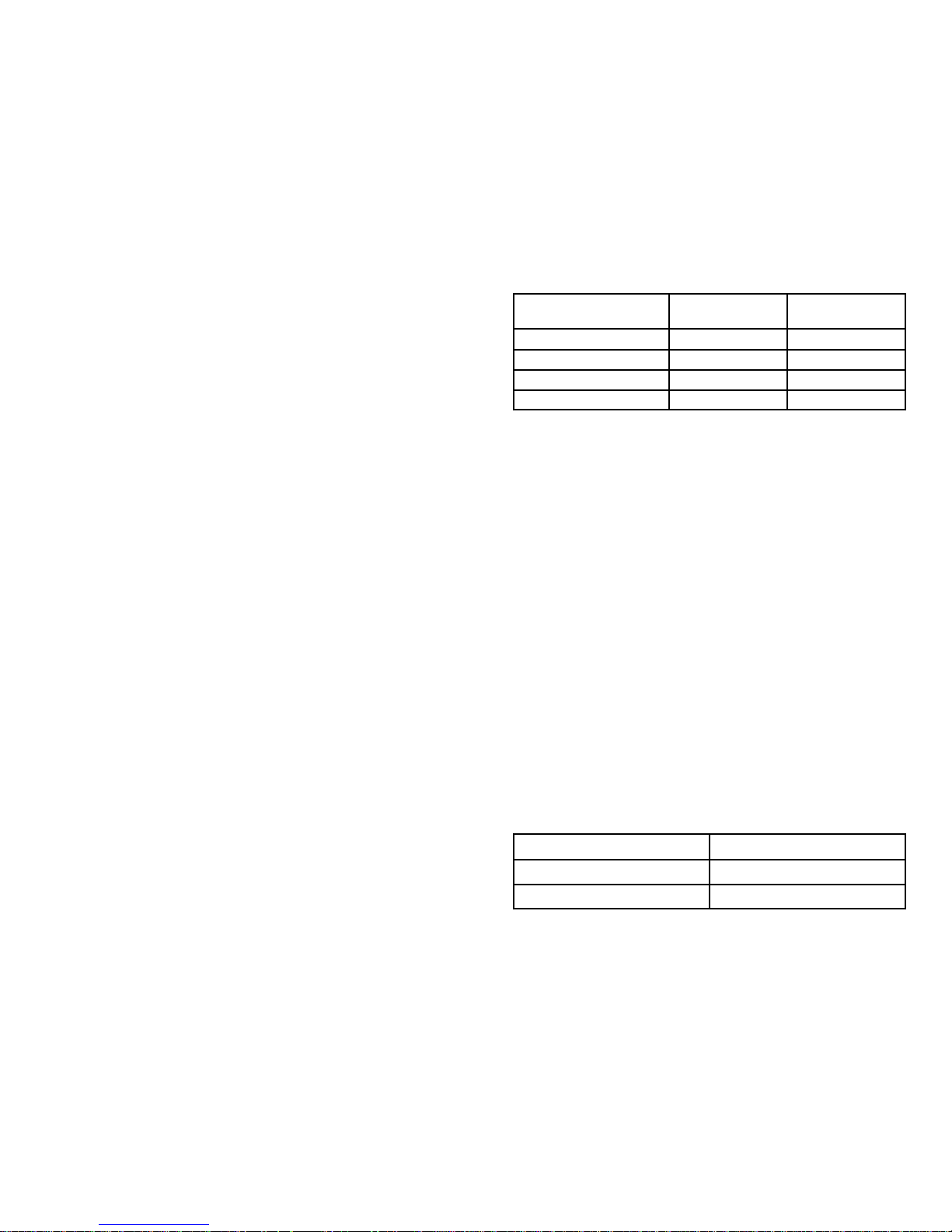
TABLE 6
DIAGNOSTIC CODES
Diagnostic LEDs are labeled DS1 and DS2. See figure 4 for location of diagnostic LEDs.
DS1 DS2 DESCRIPTION
SIMULTANEOUS
SLOW FLASH
SIMULTANEOUS
SLOW FLASH
Power on − Normal operation.
Also signaled during cooling and continuous fan.
SIMULTANEOUS
FAST FLASH
SIMULTANEOUS
FAST FLASH
Normal operation − signaled when heating demand initiated at thermostat.
SLOW FLASH ON
Primary, secondary or rollout limit switch open. Limits must close within 3 minutes
or unit goes into 1 hour Watchguard.
OFF SLOW FLASH
Low prove switch open;
OR: Blocked inlet/exhaust vent;
OR: Low prove switch closed prior to activation of combustion air inducer.
OFF FAST FLASH
High prove switch open;
OR: Blocked inlet/exhaust vent;
OR: High prove switch closed prior to activation of combustion air inducer.
ALTERNATING
SLOW FLASH
ALTERNATING
SLOW FLASH
Watchguard −− burners failed to ignite; OR limit open more than 3 minutes;
OR lost flame sense 5 times in one heating cycle;
OR pressure switch opened 5 times in one heating cycle.
SLOW FLASH OFF Flame sensed without gas valve energized.
ON
ON
OFF
ON
OFF
ON
Circuit board failure or control wired incorrectly. Check 24 and 115 volts to board.
FAST FLASH SLOW FLASH Main power polarity reversed. Switch line and neutral.
SLOW FLASH FAST FLASH Low flame signal. Measures below 0.23 microAmps. Replace flame sense rod.
ALTERNATING
FAST FLASH
ALTERNATING
FAST FLASH
The following conditions are sensed during the ignitor warm−up period only:
1) Improper main ground;
2) Broken ignitor; OR: Open ignitor circuit;
3) Line voltage below 75 volts.
(If voltage lower than 75 volts prior to ignitor warm-up, control will signal waiting on
call from thermostat, and will not respond.
NOTE − Slow flash rate equals 1 Hz (one flash per second). Fast flash rate equals 3 Hz (three flashes per second).
Low flame sense current = 0.17−0.22 microAmps.
Page 14

Page 14
WARNING
Shock hazard.
Disconnect power before servicing. Integrated
Control Board is not field repairable. If control is
inoperable, simply replace entire control.
Can cause injury or death. Unsafe operation will
result if repair is attempted.
5. Integrated Control Board(A92)
SureLight Board 100869
G60DF units are equipped with the Lennox two−stage integrated SureLight control board. The system consists of
a ignition / blower control board (figures 5 and 6) with control pin designations in tables 8 and 9 and and ignitor (figure 9). The board and ignitor work in combination to ensure furnace ignition and ignitor durability. The SureLight
integrated board controls all major furnace operations.
The board features a red LED light, for furnace status and
troubleshooting. The LED flashes in X" + Y" codes. For
example using table 10 under PRESSURE SWITCH
CODES", if the red LED flashes 2 times, then off for 2 seconds then flashes 3 times, the low pressure switch is failed
open. The board also has two 120 volt accessory terminals rated at (1) one amp each and one 24 volt accessory
terminal rated at 0.5.
Electronic Ignition
At the beginning of the heat cycle the SureLight control
monitors the first stage and second stage combustion air
inducer prove switch. The control will not begin the heating
cycle if the first stage prove switch is closed (by−passed).
Likewise the control will not begin the second stage heating
cycle if the second stage prove switch is closed, and will remain in first stage heat. However, if the second stage prove
switch closes during the first stage heat pre−purge, the control will allow second stage heat. Once the first stage prove
switch is determined to be open, the combustion air inducer is energized on low (first stage) heat speed. When the
differential in the prove switch is great enough, the prove
switch closes and a 15−second pre−purge begins. If the
switch is not proven within 2−1/2 minutes, the control goes
into Watchguard−Pressure Switch mode for a 5−minute re−
set period.
After the 15−second pre−purge period, the SureLight ignitor
warms up for 20 seconds after which the gas valve opens
for a 4−second trial for ignition. The ignitor energizes during
the trial until flame is sensed. If ignition is not proved during
the 4−second period, the control will try four more times with
an inter purge and warm−up time between trials of 35 seconds. After a total of five trials for ignition (including the initial trial), the control goes into Watchguard−Flame Failure
mode. After a 60−minute reset period, the control will begin
the ignition sequence again.
NOTE − Board 100869 DOES NOT ramp down voltage
to the ignitor. A regulated 95 volts is provided to the ig-
niter at ignition.
Two Stage Operation / Thermostat Selection Jumper
The control can be utilized in two modes: SINGLE−STAGE
thermostat or TWO−STAGE thermostat. The thermostat
selection is made using a dip switch (figure NO TAG) and
must be positioned for the particular application. The dip
switch is factory set on TWO" for use with a two−stage
thermostat with two stage heat. Re−position dip switch to
SINGLE" for use with a single stage thermostat with two
stage heat.
While in the single−stage thermostat mode (single dip
switch setting), the burners will always fire on first−stage
heat. The combustion air inducer will operate on low speed
and indoor blower will operate on low heat speed. After a
10 minute recognition period, the unit will switch to second
stage heat. While in the two−stage thermostat mode (two
dip switch setting) the burners will fire on first−stage heat.
The combustion air inducer will operate on low speed and
indoor blower will operate on low heat speed. The unit will
switch to second−stage heat on call from the indoor thermostat. If there is a simultaneous call for first and second stage
heat, the unit will fire an first stage heat and switch to second stage heat after 30 seconds of operation. See Sequence of Operation flow charts in the back of this manual
for more detail.
Page 15
Page 15
DIP Switch Settings
Switch 1 −− Thermostat Selection −− This unit may be used
with either a single−stage or two−stage thermostat. The
thermostat selection is made using a DIP switch which
must be properly positioned for the particular application.
TheDIP switch is factory−positioned for use with a two−
stage thermostat. If a single−stage thermostat is to be used,
the DIP switch must be repositioned.
a − Select OFF" for two−stage heating operation con-
trolled by a two−stage heating thermostat (factory setting);
b − Select ON" for two−stage heating operation con-
trolled by a single−stage heating thermostat. This setting provides a timed delay before second−stage heat
is initiated.
Switch 2 −− Second Stage Delay (Used with Single−
Stage Thermostat Only) −− This switch is used to deter-
mine the second stage on delay when a single−stage thermostat is being used. The switch is factory−set in the OFF
position, which provides a 10−minute delay before second−
stage heat is initiated. If the switch is toggled to the ON
position, it will provide a 15−minute delay before second−
stage heat is initiated. This switch is only activated when
the thermostat selector jumper is positioned for SINGLE−
stage thermostat use.
Switches 3 and 4 −− Heating Blower−Off Delay −− The
heating blower−on delay of 45 seconds is not adjustable.
The heating blower−off delay (time that the blower operates
after the heating demand has been satisfied) can be adjusted by moving switches 3 and 4 on the integrated control
board. The unit is shipped from the factory with a heating
blower−off delay of 90 seconds. The heating blower off
delay affects comfort and is adjustable to satisfy individual
applications. Adjust the blower off delay to achieve a supply
air temperature between 90° and 110°F at the exact moment that the blower is de−energized. Longer off delay settings provide lower supply air temperatures; shorter settings provide higher supply air temperatures.Table 7 provides the blower off timings that will result from different
switch settings.
TABLE 7
Heating Blower−Off Delay Switch Settings
Blower Off Delay
(Seconds)
Switch 3 Switch 4
60 Off On
90 Off Off
120 On Off
180 On On
Switch 5 −− Cooling Blower−Off Delay −− The cooling
blower−off delay (time that the blower operates after the
cooling demand has been satisfied) can be adjusted by
moving switch 5 on the integrated control board. The
switch is factory−set in the OFF position, which provides a
cooling blower−off delay of 45 seconds. If the switch is
toggled to the ON position, it will provide a 2−second cooling blower−off delay
On−Board Link W951
On−board link W951 is a clippable connection which connects terminals R and O on the integrated control board.
W951 must be cut when the furnace is installed in applications which include a heat pump unit and a thermostat
which features dual fuel use. If the link is left intact, terminal
O" will remain energized eliminating the HEAT MODE in
the heat pump.
On−Board Link W915
On−board link W915 is a clippable connection which connects terminals Y1 and Y2 on the integrated control board.
W915 must be cut if two−stage cooling will be used. If the
link is not cut the outdoor unit will operate in first−stage cooling only.
Page 16
Page 16
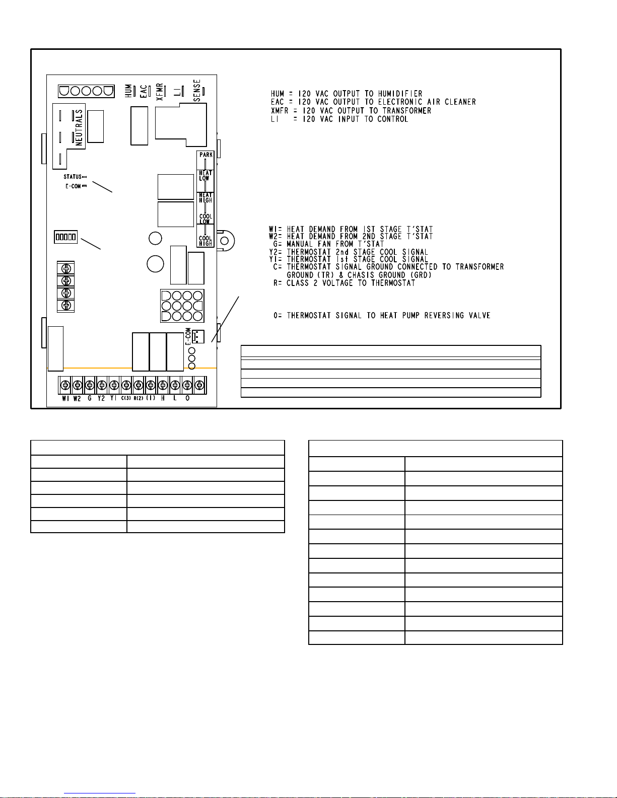
CONTROL BOARD 100869
FIGURE 5
THERMOSTAT CONNECTIONS (TB1)
1/4" QUICK CONNECT TERMINALS
DIP SWITCH FUNCTIONS
DIP
SWITCHES
DIAGNOSTIC
LEDs
ON−BOARD
LINKS
1= ERROR CODE RECALL
H= 24V HUMIDIFIER OUTPUT
L= LENNOX SYSTEM OPERATION MONITOR
SENSE = 120 VAC OUTPUT TO FLAME SENSER
NEUTRALS= 120 VAC NEUTRAL
PARK = DEAD TERMINAL FOR UNUSED BLOWER LEAD
HEAT LOW = 120 VAC OUTPUT TO CIRC BLWR −− LOW HT SPEED
HEAT HIGH/ COOL LOW = 120 VAC OUTPUT TO CIRC BLWR −−
HIGH HEAT AND LOW COOL SPEED
COOL HIGH = 120 VAC OUTPUT TO CIRC BLWR −− HIGH COOL SPEED
DIP SWITCH(ES) FUNCTION
1 −− 2 Stage T’stat Selects t/stat type (single or two−stage)
2 −− 2nd Stage Delay Second stage ON delay (single−stage t’stat)
3 & 4 −− Heat Off Delay Heating fan OFF delay
5 −− Cool Off Delay Cooling fan OFF delay
W915
W951
TABLE 8
SureLight Board 5 Pin Terminal Designation
PIN # Function
1 Ignitor
2 Combustion Air Inducer High Speed
3 Combustion Air Inducer Low Speed
4 Combustion Air Inducer Neutral
5 Ignitor Neutral
TABLE 9
SureLight Board 12Pin Terminal Designation
PIN # Function
1 Gas Valve High Fire
2 Second Stage Prove Switch
3 Rollout In
4 Ground
5 24V Hot
6 Primary Limit In
7 Gas Valve Low Stage
8 Gas Valve Common
9 24V Neutral
10 Ground
11 Rollout Switch Out
12 1st Stage Prove Switch
Page 17

Page 17
CONTROL BOARD 100869
FIGURE 6
Page 18
Page 18
TABLE 10
FLASH CODE
(X + Y)
STATUS / ERROR DESCRIPTION
FLASH CODE DESCRIPTIONS
Pulse A 1/4 second flash followed by four seconds of off time.
Heartbeat Constant 1/2 second bright and 1/2 second dim cycles.
X + Y
LED flashes X times at 2Hz, remains off for two seconds, flashes Y times at 2Hz, remains off for four
seconds, then repeats.
Pulse Power on − Standby.
Heartbeat Normal operation − signaled when heating demand initiated at thermostat.
FLAME CODES
1 + 2 Low flame current −− run mode.
1 + 3 Flame sensed out of sequence −− flame still present.
PRESSURE SWITCH CODES
2 + 3 Low pressure switch failed open.
2 + 4 Low pressure switch failed closed.
2 + 5 High pressure switch failed open.
2 + 6 High pressure switch failed closed.
2 + 7 Low pressure switch opened during ignition trial or heating demand.
LIMIT CODE
3 + 1 Limit switch open.
WATCHGUARD CODES
4 + 1 Watchguard −− Exceeded maximum number of retries.
4 + 2 Watchguard −− Exceeded maximum number of retries or last retry was due to pressure switch opening.
4 + 3 Watchguard −− Exceeded maximum number of retries or last retry was due to flame failure.
4 + 5 Watchguard −− Limit remained open longer than three minutes.
4 + 6
Watchguard −− Flame sensed out of sequence; flame signal gone.
4 + 7 Ignitor circuit fault −− Failed ignitor or triggering circuitry.
4 + 8 Low line voltage.
HARD LOCKOUT CODES
5 + 1 Hard lockout −− Rollout circuit open or previously opened.
5 + 2 Control failed self check, internal error (control will restart if error recovers).
5 + 3 No Earth ground (control will restart if error recovers).
5 + 4 Reversed line voltage polarity (control will restart if the error recovers).
5 + 6 Low secondary (24VAC) voltage.
Error Code Storage
The ignition control stores the last ten error codes in
memory. The codes are retained in case of power loss.
Error Code Review
1 − Short R (2) to (1). Within 1/2 second, the STATUS LED
will stay lit continuously to indicate that the short was
sensed.
2 − Continue to hold the short between R (2) to (1). After 5
seconds, STATUS LED will go from being continuously
lit to off. This indicates that error code review is pending.
3 − Remove R (2) to (1) short within ten seconds of STA-
TUS LED turning off. This activates error code review.
4 − Last ten error codes will be flashed on the STATUS
LED.
5 − After final error code is indicated, STATUS LED will
flash to indicate normal operation.
Clearing Error Codes
1 − Short R (2) to (1). Within 1/2 second, the STATUS LED
will stay lit continuously to indicate that the short was
sensed.
2 − Continue to hold the short between R (2) to (1). After 5
seconds, STATUS LED will go from being continuously
lit to off.
3 − Continue to hold the short between R (2) to (1) beyond
ten seconds after STATUS LED has turned off. STATUS LED will turn on, indicating that error codes have
been cleared.
4 − Remove R (2) to (1) short. STATUS LED will flash to in-
dicate normal operation.
Page 19
Page 19
6. Blower Motors and Capacitors
All G60DFunits use direct drive blower motors. All motors
are 120V permanent split capacitor motors to ensure maxi-
mum efficiency. Ratings for capacitors will be on motor
nameplate. See SPECIFICATIONS section for motor speci-
fications. Follow the steps in figure 7 for blower removal.
NOTE − Shafts on 1 HP motors have 2 flat sides and are
matched with blower wheels with 2 set screws.
FIGURE 7
SUPPLY AIR BLOWER
AND SECONDARY LIMIT (S)
To Remove Blower From Unit:
1. Disconnect Power, 2. Remove internal flue pipe and
chase (Section VI− Heat exchanger and Burners). 3. Re-
move Control Box, 4. Remove Bolts. 5. Unplug Motor
Wires From Control Board. Then Slide Out Front of Unit.
SECONDARY
LIMIT
CAPACITOR
MOTOR/BLOWER
ASSEMBLY
7. Ignitor
The SureLight ignitor is made of durable silicon nitride. Ignitor longevity is enhanced by controlling voltage to the ignitor. Board 18M34 finds the lowest ignitor temperature
which will successfully light the burner, thus increasing the
life of the ignitor. Due to this feature of the board, voltage
cannot be measured so ignitor must be ohmed. Board
100869 provides a regulated 95 volts to the ignitor for consistent ignition and long ignitor life. Ohm value for ignitors
with SureLight board 18M34 should be 10.9 to 19.7. Ohm
value for ignitors with board 100869 should be 25 to 47.
See figure 8 and 9 (make note of control board used) for
ignitor location.
NOTE − The G60DF(X) furnace contains electronic
components that are polarity sensitive. Make sure that
the furnace is wired correctly and is properly grounded.
8. Flame Sensor
A flame sensor is located on the left side of the burner support. See figure 10 and 11 (make note of control board
used). The sensor is mounted on the flame rollout plate and
the tip protrudes into the flame envelope of the left−most
burner. The sensor can be removed for service without removing any part of the burners. During operation, flame is
sensed by current passed through the flame and sensing
electrode. The SureLight control allows the gas valve to remain open as long as flame signal is sensed.
Page 20

Page 20
FIGURE 8
5/16"
13/32’
5/8
"
SureLight Board 18M34 Ignitor Location
BURNERS TOP VIEW
BURNERS FRONT VIEW
MEASUREMENT IS TO
I.D. OF RETENTION
RING
IGNITOR
BRACKET
FIGURE 9
21/64"
7/32’
5/8
"
SureLight Board 100869 Ignitor Location
BURNERS TOP VIEW
BURNERS FRONT VIEW
MEASUREMENT IS TO
I.D. OF RETENTION
RING
IGNITOR
BRACKET
FIGURE 10
NORMAL FLAME SIGNAL > 0.23 MICROAMPS
LOW FLAME SIGNAL < 0.22 MICROAMPS
DROP OUT SIGNAL = 0.16 MICROAMPS
5/16"
SureLight Board 18M34 Sensor
FIGURE 11
NORMAL FLAME SIGNAL > 1.50 MICROAMPS
LOW FLAME SIGNAL <
1.40 MICROAMPS
DROP OUT SIGNAL = 0.20 MICROAMPS
5/16"
SureLight Board 100869 Sensor
Page 21

Page 21
9. Combustion Air Inducer (B6)
All units use a two−stage combustion air inducer to move air
through the burners and heat exchanger during heating operation. The blower uses a 120VAC motor. The motor operates during all heating operation and is controlled by furnace / blower control (A92). The inducer also operates for
15 seconds before burner ignition (pre-purge) and for 5
seconds after the gas valve closes (post-purge). The inducer operates on low speed during first−stage heat, then
switches to high speed for second stage heat.
A proving switch connected to the combustion air inducer orifice plate is used to prove inducer operation. The combustion
air inducer orifice will be different for each model. See table 11
for orifice sizes. The switch monitors air pressure in the inducer housing. During normal operation, the pressure in the
housing is negative. If pressure becomes less negative (signifying an obstruction) the proving switch opens. When the
prove switch opens, the furnace control (A92) immediately
closes the gas valve to prevent burner operation.
TABLE 11
G60DF Unit
C.A.I. Orifice Size
−045−1, −2 1.250"
−070−1, −2 1.563"
−070−4 and later 1.500"
−090−1, −2 1.875"
−090−4 and later 1.750"
−110 all units 2.156"
−135−2, −3 2.600"
10. Flame Rollout Switches (S47)
In all G60DF−1, −2 and −3 units, flame rollout switch is a high
temperature limit located on top of the burner box. Each
furnace is equipped with two identical switches (−045 model will have one switch located in the center). One switch is
located over the leftmost burner and the other switch is located over the rightmost burner. All G60DF−4 and later
models have the two switches located on brackets inside
the burner box. S47 is a N.C. SPST manual-reset limit.
When S47 senses rollout, the circuit breaks and the ignition
control immediately stops ignition and closes the gas
valve.
If unit is running and flame rollout is detected, the gas valve
will close and ignition control will be disabled. Rollout can
be caused by a blocked heat exchanger, flue or lack of
combustion air. The switch is factory set to trip (open) at
210°F and cannot be adjusted. The switch can be manually
reset. To manually reset a tripped switch, push the reset button located on the control.
11. Primary Limit Control (S10)
The primary limit (S10) is located in the heating vestibule panel. When excess heat is sensed in the heat exchanger, the
limit will open. If the limit is open, the furnace control energizes
the supply air blower and closes the gas valve. The limit automatically resets when unit temperature returns to normal. The
switch must reset within three minutes or the SureLight board
will go into Watch guard for one hour. The switch is factory
set and cannot be adjusted. The switch may have a different
set point for each unit model number. Refer to Repair Parts
Handbook for correct length and set point.
12. Secondary Limit Controls (S21)
The secondary limit (S21) is located in the blower compartment on the back side of the blower housing. See figure 7.
When excess heat is sensed in the blower compartment, the
limit will open. If the limit is open, the furnace control energizes
the supply air blower and closes the gas valve. The limit automatically resets when unit temperature returns to normal.
G60DF−1 through −4 units use a surface type limit that is factory set to open at 125°F. G60DF−5 and later units use an air
stream limit factory set to open at 135°. The secondary limit
cannot be adjusted.
13. Gas Valve
All units use a two−stage gas valve manufactured by
Honeywell (figure 13). The valve is internally redundant to
assure safety shut−off. If the gas valve must be replaced,
the same type valve must be used.
24VAC terminals and gas control knob are located on the
valve. All terminals on the gas valve are connected to wires
from the electronic ignition control. 24V applied to the terminals
energizes the valve.
Inlet and outlet pressure taps are located on the valve. A regulator adjustment screw is located on the valve.
LPG change over kits are available from Lennox. Kits include
burner orifices and a gas valve regulator conversion kit.
Page 22

Page 22
14. Combustion Air Inducer
Prove Switch (S18)
S18 is a dual combustion air proving switch (first and second
stage) located on the combustion air inducer orifice bracket.
The switch is connected to the combustion air inducer housing by means of a flexible silicone hose. It monitors negative
air pressure in the combustion air inducer housing.
The switches are a single-pole single-throw proving switch
electrically connected to the furnace control. The purpose of
the switch is to prevent burner operation if the combustion
air inducer is not operating or if the flue becomes obstructed.
On heat demand (first or second stage) the switch senses
that the combustion air inducer is operating. It closes a circuit to the furnace control when pressure inside the combustion air inducer decreases to a certain set point.
Set points vary depending on unit size. See tables 12, 13
and 14. The pressure sensed by the switch is negative relative to atmospheric pressure. If the flue becomes obstructed during operation, the switch senses a loss of negative pressure (pressure becomes more equal with atmospheric pressure) and opens the circuit to the furnace control and gas valve. A bleed port on the switch allows relatively dry air in the vestibule to purge switch tubing, to prevent condensate build up.
The switch is factory set and is not field adjustable. It is a
safety shut-down control in the furnace and must not be by−
passed for any reason. If switch is closed or by−passed, the
control will not initiate ignition at start up.
FIGURE 12
DUAL COMBUSTION AIR PROVE SWITCH
BRACKET
TAP
LOW FIRE SWITCH
HIGH FIRE SWITCH
TABLE 12
0’ to 4500’
G60DF Unit
Set Point High
Heat
Set Point Low
Heat
−045 0.40" 0.20"
−070 0.40" 0.20"
−090 0.45" 0.20"
−110 0.50" 0.20"
−135 0.50" 0.20"
TABLE 13*
4501’ to 7500’
G60DF Unit
Set Point High
Heat
Set Point Low
Heat
−045 0.40" 0.20"
−070 0.40" 0.20"
−090 0.40" 0.20"
−110 0.45" 0.20"
−135 0.45" 0.20"
*Unit requires conversion kit at this altitude. See High Altitude table.
TABLE 14*
7501’ to 10,000’
G60DF Unit
Set Point High
Heat
Set Point Low
Heat
−045 0.35" 0.20"
−070 0.35" 0.20"
−090 0.35" 0.20"
−110 0.40" 0.20"
−135 0.40" 0.20"
*Unit requires conversion kit at this altitude. See High Altitude table.
Page 23

Page 23
II−PLACEMENT AND INSTALLATION
Make sure unit is installed in accordance with installation
instructions and applicable codes.
III−START-UP
A−Preliminary and Seasonal Checks
1 − Inspect electrical wiring, both field and factory installed
for loose connections. Tighten as required.
2 − Check voltage at disconnect switch. Voltage must be
within range listed on the nameplate. If not, consult the
power company and have voltage condition corrected
before starting unit.
B−Heating Start-Up
WARNING
Shock and burn hazard.
G60DF units are equipped with a hot surface ignition
system. Do not attempt to light manually.
1 − STOP! Read the safety information at the beginning of
this section.
2 − Set the thermostat to the lowest setting.
3 − Turn off all electrical power to the unit.
4 − This furnace is equipped with an ignition device which
automatically lights the burners. Do not try to light the
burners by hand.
5 − Remove the upper access panel.
6 − Honeywell VR8205 Gas Valve − Turn knob on gas
valve clockwise
to OFF. Do not force. See figure
13.
7 − Wait five minutes to clear out any gas. If you then smell
gas, STOP! Immediately call your gas supplier from a
neighbor’s phone. Follow the gas supplier’s instructions. If you do not smell gas go to next step.
FIGURE 13
HONEYWELL VR8205 Series Gas Valve
GAS VALVE SHOWN IN OFF POSITION
MANIFOLD
PRESSURE
TAP
lOW FIRE
ADJUSTMENT
SCREW
(under cap)
INLET PRESSURE TAP
HIGH FIRE
ADJUSTMENT
SCREW
(under cap)
8 − Honeywell VR8205 Gas Valve − Turn knob on gas
valve counterclockwise
to ON. Do not force. See
figure 13.
9 − Replace the upper access panel.
10− Turn on all electrical power to to the unit.
11− Set the thermostat to desired setting.
NOTE − When unit is initially started, steps 1 through 11
may need to be repeated to purge air from gas line.
Turning Off Gas To Unit
1 − Set thermostat to lowest setting.
2 − Turn off all electrical power to unit if service is to be per-
formed.
3 − Remove access panel.
4 − Turn knob on Honeywell valve clockwise
to OFF. Do
not force.
5 − Replace access panel.
C−Safety or Emergency Shutdown
Turn off unit power. Close manual and main gas valves.
D−Extended Period Shutdown
Turn off thermostat or set to UNOCCUPIED" mode. Close
all gas valves (both internal and external to unit) to guarantee no gas leak into combustion chamber. Turn off power to
unit. All access panels and covers must be in place and secured.
Page 24

Page 24
IV−HEATING SYSTEM SERVICE CHECKS
A−C.S.A. Certification
All units are C.S.A. (formally A.G.A. and C.G.A. combined)
design certified without modifications. Refer to the G60DF
Installation Instruction.
B−Gas Piping
CAUTION
If a flexible gas connector is required or allowed by
the authority that has jurisdiction, black iron pipe
shall be installed at the gas valve and extend outside
the furnace cabinet.
WARNING
Do not exceed 600 in−lbs (50 ft−lbs) torque when attaching the gas piping to the gas valve.
Gas supply piping should not allow more than 0.5"W.C. drop
in pressure between gas meter and unit. Supply gas pipe
must not be smaller than unit gas connection.
Compounds used on gas piping threaded joints should be
resistant to action of liquefied petroleum gases.
C−Testing Gas Piping
IMPORTANT
In case emergency shutdown is required, turn off
the main shut-off valve and disconnect the main
power to unit. These controls should be properly
labeled by the installer.
When pressure testing gas lines, the gas valve must be disconnected and isolated. Gas valves can be damaged if
subjected to more than 0.5psig (14" W.C.). See figure 14.
FIGURE 14
MANUAL MAIN SHUT−OFF VALVE
GAS VALVE
CAP
GAS PIPING TEST PROCEDURE
When checking piping connections for gas leaks, use preferred means. Kitchen detergents can cause harmful corrosion on various metals used in gas piping. Use of a specialty
Gas Leak Detector is strongly recommended. It is available
through Lennox under part number 31B2001. See Corp.
8411−L10, for further details.
Do not use matches, candles, flame or any other source of
ignition to check for gas leaks.
D−Testing Gas Supply Pressure
When testing supply gas pressure, connect test gauge to
inlet pressure tap on unit gas valve (GV1). See figure 13.
Check gas line pressure with unit firing at maximum rate.
Low pressure may result in erratic operation or underfire.
High pressure can result in permanent damage to gas
valve or overfire. See table 15 for operating pressure at unit
gas connection (line).
On multiple unit installations, each unit should be checked
separately, with and without units operating. Supply pressure must fall within range listed in table 15.
E−Check Manifold Pressure
After line pressure has been checked and adjusted, check
manifold pressure. Move pressure gauge to outlet pressure tap located on unit gas valve (GV1). Checks of manifold pressure are made as verification of proper regulator adjustment. Manifold pressure can be measured at any time
the gas valve is open and is supplying gas to the unit. See
table 15 for normal operating manifold pressure. See HIGH
ALTITUDE table (table of contents) for high altitude manifold
pressures.
Page 25

Page 25
TABLE 15
All G60DF Units
Natural LP
Line Pressure WC" 4.5 − 10.5 11.0 − 13.0
Manifold Pressure High
Heat WC"
3.5 10.0
Manifold Pressure Low
Heat WC"
1.7 4.9
IMPORTANT
For safety, connect a shut-off valve between the
manometer and the gas tap to permit shut off of
gas pressure to the manometer.
The gas valve is factory set and should not require adjustment. All gas valves are factory regulated.
Manifold Adjustment Procedure:
1 − Connect a test gauge to manifold pressure tap on gas
valve. See figure or 13 for tap location. Start unit and
allow 5 minutes for unit to reach steady state.
2 − While waiting for the unit to stabilize, notice the flame.
Flame should be stable and should not lift from burner.
Natural gas should burn blue. L.P. gas should burn
mostly blue with some orange streaks.
3 − After allowing unit to stabilize for 5 minutes, record
manifold pressure.
NOTE−Shut unit off and remove manometer as soon as
an accurate reading has been obtained. Take care to replace pressure tap plug.
F− Proper Gas Flow (Approximate)
Furnace should operate at least 5 minutes before checking gas flow. Determine time in seconds for two revolutions of gas through the meter. (Two revolutions assures a
more accurate time.) Divide by two and compare to time
in table 16 below. If manifold pressure matches table 15
and rate is incorrect, check gas orifices for proper size and
restriction.
NOTE− To obtain accurate reading, shut off all other gas
appliances connected to meter.
TABLE 16
GAS METER CLOCKING CHART
G60DF
Unit
Seconds for One Revolution
Natural LP
1 cu ft
Dial
2 cu ft
Dial
1 cu ft
Dial
2 cu ft
DIAL
−045 82 164 205 410
−70 55 110 136 272
−90 41 82 102 204
−110 33 66 82 164
−135 27 54 68 136
Natural−1000 btu/cu ft LP−2500 btu/cu ft
IMPORTANT
For safety, shut unit off and remove manometer as
soon as an accurate reading has been obtained.
Take care to replace pressure tap plug.
G− Proper Combustion
Furnace should operate minimum 15 minutes with correct
manifold pressure and gas flow rate before checking combustion. See sections E− and F−. Take combustion sample
beyond the flue outlet and compare to the tables below.
The maximum carbon monoxide reading should not exceed 100 ppm.
TABLE 17
High Heat
Unit Btuh
CO2%
For Nat
CO2%
For L.P.
045 6.0 − 7.0 6.5 − 7.5
070 6.7 − 7.7 7.0 − 8.0
090 6.7 − 7.7 8.0 − 9.0
110 7.0 − 8.0 8.3 − 9.3
135 6.7 − 7.7 7.5 − 8.5
TABLE 18
Low Heat
Unit Btuh
CO2%
For Nat
CO2%
For L.P.
045 4.0 − 5.0 4.5 − 5.5
070 4.3 − 5.3 4.7 − 5.7
090 4.5 − 5.5 4.9 − 5.9
110 4.7 − 5.7 5.2 − 6.2
135 4.5 − 5.5 5.0 − 6.0
Page 26

FIGURE 15
TRANSDUCER
(PART #78H5401)
Page 26
H−Flame Signal
A microamp DC meter is needed to check the flame signal
on the ignition control.
Flame (microamp) signal is an electrical current which passes
from the furnace control through the sensor during unit operation. Current passes from the sensor through the flame to
ground to complete a safety circuit.
To Measure Flame Signal − Ignition Control:
A transducer (Part
#78H5401 available
from Lennox Repair
Parts) is required to
measure flame signal if
meter used will not read
a low micro amp signal.
Seefigure15. The
transducer converts microamps to volts on a 1:1 conversion. See figures 10 and 11 for flame signal. A digital
readout meter must be used. The transducer plugs into
most meters. See figure 16 for proper use of transducer.
1 − Set the volt meter to the DC voltage scale. Insert
transducer into the VDC and common inputs. Observe correct polarities. Failure to do so results in
negative (−) values.
2 − Turn off supply voltage to control.
3 − Disconnect ignition control flame sensor wire from the
flame sensor.
4 − Connect (−) lead of the transducer to flame sensor.
5 − Connect (+) lead of transducer to the ignition control sen-
sor wire.
6 − Turn supply voltage on and close thermostat contacts to
cycle system.
7 − When main burners are in operation for two minutes, take
reading. Remember 1 DC volt = 1 DC microamp.
SET DIAL TO MEASURE
VDC
(+)
(−) TO
FLAME SENSOR
NOTE−MUST USE DIGITAL METER
RED COLLAR
INDICATES
POSITIVE
LEAD
(+) TO
IGNITION
CONTROL
SENSOR
WIRE
FIGURE 16
(−)
V−TYPICAL OPERATING CHARACTERISTICS
A−Blower Operation and Adjustment
1 − Blower operation is dependent on thermostat control
system.
2 − Generally, blower operation is set at thermostat sub-
base fan switch. With fan switch in ON position, blower
operates continuously. With fan switch in AUTO position,
blower cycles with demand or runs continuously while
heating or cooling circuit cycles.
3 − Depending on the type of indoor thermostat, blower
and entire unit will be off when the system switch is in
OFF position.
B−Temperature Rise
Temperature rise for G60DF units depends on unit input,
blower speed, blower horsepower and static pressure as
marked on the unit rating plate. The blower speed must be
set for unit operation within the range of TEMP. RISE °F"
listed on the unit rating plate.
To Measure Temperature Rise:
1 − Place plenum thermometers in the supply and return air
plenums. Locate supply air thermometer in the first horizontal run of the plenum where it will not pick up radiant
heat from the heat exchanger.
2 − Set thermostat to highest setting.
3 − After plenum thermometers have reached their high-
est and steadiest readings, subtract the two readings.
The difference should be in the range listed on the unit
rating plate. If the temperature is too low, decrease
blower speed. If temperature is too high, first check the
firing rate. Provided the firing rate is acceptable, in-
crease blower speed to reduce temperature. To
change blower speed taps see the Blower Speed Taps
section in this manual.
Page 27

FIGURE 17
STATIC PRESSURE TEST
Page 27
C−External Static Pressure
1 − Tap locations shown in figure 17.
2 − Punch a 1/4" diameter hole
in supply and return air plenums. Insert manometer
hose flush with inside edge
of hole or insulation. Seal
around the hose with permagum. Connect the zero end
of the manometer to the discharge (supply) side of the system. On ducted systems, connect the other end of manometer to the return
duct as above. For systems with non−ducted returns,
leave the other end of the manometer open to the atmosphere.
3 − With only the blower motor running and the evaporator
coil dry, observe the manometer reading. Adjust blower motor speed to deliver the air desired according to
the job requirements.
4 − External static pressure drop must not be more than
0.5" W.C.
5 − Seal around the hole when the check is complete.
D−Blower Speed Taps
Blower speed tap changes are made on the SureLight control board. See figure 4. The unused tap must be secured
on dummy terminals "PARK " on the SureLight board. The
high heating tap is connected to the "HI HEAT " terminal
and the low heating / continuous blower tap is connected to
the "LO HEAT" terminal. The cooling tap is connected to the
COOL" tap.
To change existing heat tap, turn off power then switch out
speed tap on "HI HEAT" or LO HEAT" with tap connected
to "PARK ". See table 19 for blower motor tap colors for
each speed.
TABLE 19
* On G60DF−045 only, jumper wire between
HI and LO heat is factory provided.
*
VI−MAINTENANCE
WARNING
Disconnect power before servicing unit.
CAUTION
Label all wires prior to disconnection when servicing
controls. Wiring errors can cause improper and dangerous operation. Verify proper operation after servicing.
At the beginning of each heating season, a qualified technician should check the system as follows:
A−Blower
Check the blower wheel for debris and clean if necessary.
The blower motors are prelubricated for extended bearing
life. No further lubrication is needed.
WARNING
The blower access panel and vent pipe must be securely in place when the blower and burners are operating. Gas fumes, which could contain carbon
monoxide, can be drawn into living space resulting
in personal injury or death.
B−Filters
All filters are installed external to the unit. Filters should be
inspected monthly. Clean or replace the filters when necessary to ensure that the furnace operates properly. Replacement filters must be rated for high velocity airflow.
C−Flue and Chimney
Check the flue pipe, chimney and all connections for tightness and to make sure there is no blockage.
D−Electrical
1 − Check all wiring for loose connections.
2 − Check for the correct voltage at the furnace (furnace
operating).
3 − Check amp−draw on the blower motor.
Motor Nameplate__________Actual__________
E−Heat Exchanger and Burners
NOTE − Use papers or protective covering in front of the furnace during cleaning.
Cleaning the heat exchanger requires a steel spring
snake," a reversible drill and a vacuum cleaner. The steel
spring snake may be constructed using a 4 ft. long by 1/4
inch diameter steel wire cable and a 1/4 inch diameter wire
brush. These items are available at a hardware store. Insert wire end of brush into the open end of the spring cable.
Crimp the cable around the brush so that the brush is secured and will not come off during cleaning. Attach the other end of the cable to the reversible drill to complete the tool
for cleaning the heat exchanger.
1 − Turn off both electrical and gas supplies to the furnace.
Remove the furnace access panels.
Page 28

Page 28
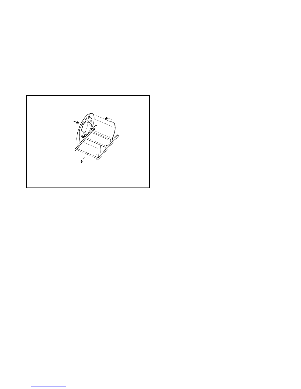
2 −Remove the three screws that secure the vent pipe to
the flue collar.
3 −Remove the screw that secures the internal flue pipe to
the combustion air inducer. See figure 18.
4 −Scrape away the silicone sealant that is between the
internal flue pipe and the combustion air inducer.
5 −Pull the internal flue pipe into the chase.
6 −Label and disconnect the pressure switch wires.
7 − Remove the four screws that secure the combustion
air inducer. Carefully remove the combustion air inducer to avoid damaging the blower gasket. If the gasket is
damaged, it must be replaced to prevent leakage. See
figure 20.
8 −Remove the collector box located behind the combus-
tion air inducer. Be careful with the collector box gasket. If the gasket is damaged, it must be replaced to
prevent leakage.
9 −Label the wires from gas valve and rollout switches,
then disconnect them.
10 −Disconnect gas supply piping. Remove four screws
securing the burner manifold assembly to the vestibule
panel and remove the assembly from the unit.
11 −NO
x
units only − Remove the three screws that attach
the NO
x
insert to the corbel at the entrance to each
heat exchanger section. Carefully remove the NO
x
in-
sert from each section. See figure 19.
G60DF(X) Internal Flue Pipe and Chase
FIGURE 18
Unit Top Cap
Internal Flue
Pipe
with Adaptor
Flue Chase
with Gaskets
Screw (1)
Internal
Flue Pipe
RTV
Silicone
Sealant
Combustion
Air Inducer
NO
x
INSERTS
(X models only)
FIGURE 19
NOx INSERT
12 −Insert the brush end of cable snake into the top of one
of the heat exchanger openings. Do not force the
cable into the heat exchanger. Insert the cable and
operate the drill on slow speed. Move the cable in and
out of the heat exchanger section three or four times or
until sufficient cleaning is accomplished. Reverse drill
and slowly work the cable out of opening.
13 −Repeat procedure for each heat exchanger section.
14 −After each of the top heat exchanger sections has
been cleaned, insert the brush end of the cable snake
into the bottom openings of each of the heat exchanger
sections and clean as described in step 12.
15 −Remove the cable from the heat exchanger. Use a
vacuum cleaner to remove debris knocked loose during cleaning.
NOTE − Take care not to inhale loose debris and
avoid eye contact. Safety glasses and surgical
mask should be worn when using vacuum cleaner.
FIGURE 20
G60DF(X) CAI & Burner Box Removal
Burner Box Assembly
Heat Exchanger
Combustion Air Inducer
Page 29

Page 29
16 −Attach the exhaust end (positive pressure) of the vacu-
um cleaner to the top of the heat exchanger section.
Any loose debris will be forced to the bottom of the heat
exchanger section. Vacuum debris from bottom openings.
17 −Replace collector box and combustion air inducer.
Check gaskets for damage. Damaged gaskets must
be replaced to avoid heat exchanger leaks. Replace all
screws to the collector box and combustion air inducer.
Failure to replace all screws may cause leaks.
18 −To clean the burner, run a vacuum cleaner with a soft
brush attachment over the face of burners. Inspect inside the burners and crossovers for any blockage.
Clean the inside of the burner if necessary.
19 −NO
x
Units − Reattach the NOx inserts to the corbels at
the entrance to each heat exchanger opening. See figure 19.
20 −Reinstall the burner/manifold assembly on the vesti-
bule panel.
21 −Reconnect wires to pressure switch, roll−out switches,
gas valve and combustion air inducer. Refer to unit wiring diagram.
22 −Use screws to resecure the junction box to the cabinet.
23 −Apply RTV/high temperature silicone sealant between
the internal flue pipe and the combustion air inducer.
24 −Use one screw to resecure the internal flue pipe to the
combustion air inducer.
25 −Use three screws to resecure the vent pipe to the flue
collar.
WARNING
The blower access panel and vent pipe must be securely in place when the blower and burners are operating. Gas fumes, which could contain carbon
monoxide, can be drawn into living space resulting
in personal injury or death.
26 −Reconnect the gas supply piping.
27 −Turn on power and gas supply to the unit.
28 −Set thermostat and check for proper operation.
29 −Check all piping connections, factory and field, for gas
leaks. Use a leak detecting solution or other preferred
means.
CAUTION
Some soaps used for leak detection are corrosive to
certain metals. Carefully rinse piping thoroughly after leak test has been completed. Do not use
matches, candles, flame or other sources of ignition
to check for gas leaks.
30 −If a leak is detected, shut gas and electricity off and re-
pair leak.
31 −Replace front access panels.
Page 30

Page 30
VII− Wiring and Sequence of Operation
A−G60DF−1, −2, −3 with SureLight Board 18M34
Page 31

Page 31
B−G60DF−4, −5 with SureLight Board 18M34
Page 32

Page 32
G60DF Units with SureLight Board 18M34
Sequence depends on type thermostat used. Units are
applicable for single stage or two stage thermostats.
Both type thermostats are described below. Thermostat jumper E20 dictates which mode unit will operate
in. See flow chart for more sequence detail.
SureLight Control Self Check
When there is a call for heat, the SureLight integrated control runs a self check. The control checks for S10 primary
limit, S21 secondary limit (s) and S47 rollout switch normally closed contacts. The control also checks for S102
high heat and S128 low heat prove switch normally open
contacts. Once self check is complete and all safety
switches are operational, heat call can continue.
Two−Stage Thermostat, Two Stage Heat. Jumper E20
set at TWO".
1− SureLight control energizes combustion air inducer B6
on low heat speed. Combustion air inducer runs until
S128 low heat prove switch contacts close (switch
must close within 2 1/2 minutes or control goes into
Watchguard Pressure Switch mode. High heat prove
switch S102 may also close). A 15 second pre−purge
follows once S128 closes.
2− SureLight control begins 20 second ignitor warm up
period.
3− Gas valve opens on first stage for a 4 second trial for
ignition. Ignitor stays energized during the trial or until
flame sensed.
4− Flame is sensed, gas valve remains on first stage heat,
ignitor de−energizes.
5− After 45 second delay, indoor blower B3 is energized
on low heat speed.
The furnace will stay in this mode until first stage demand is satisfied OR a second stage heat demand is
initiated.
6− Second stage heat demand initiated. A 30 second sec-
ond stage recognition period begins.
7− The combustion air inducer ramps up to high heat
speed.
8− S102 high heat prove switch closes and the gas valve
energizes second stage heat.
9− B3 indoor blower ramps up to high heat speed.
Single−Stage Thermostat, Two Stage Heat. Jumper
E20 set at SINGLE"
1− SureLight control energizes combustion air inducer B6
on low heat speed. Combustion air inducer runs until
S128 low heat prove switch contacts close (switch
must close within 2 1/2 minutes or control goes into
Watchguard Pressure Switch mode. High heat prove
switch S102 may also close). A 15 second pre−purge
follows once S128 closes.
2− SureLight control begins 20 second ignitor warm up
period.
3− Gas valve opens on first stage for a 4 second trial for
ignition. Ignitor stays energized during the trial or until
flame sensed.
4− Flame is sensed, gas valve remains on first stage heat,
ignitor de−energizes.
5− After 45 second delay, indoor blower B3 is energized
on low heat speed.
6− A 10 minute (factory set) or 15 minute (field set) second
stage heat delay period begins.
7− The combustion air inducer ramps up to high heat
speed.
8− S102 high heat prove switch closes and the gas valve
energizes second stage heat.
9− B3 indoor blower ramps up to high heat speed.
Page 33

Page 33
G60DF Units with SureLight Board 18M34
HEATING SEQUENCE OF OPERATION
NORMAL AND ABNORMAL HEATING MODE
CONTROL SELF−CHECK OKAY?
YES
GAS VALVE OFF. COMBUSTION AIR INDUCER OFF.
INDOOR BLOWER OFF. (RESET CONTROL BY
TURNING MAIN POWER OFF.) DS1 ON, DS2 ON
NO
POLARITY REVERSED.
DS1 −− FAST FLASH
DS2 −− SLOW FLASH
POWER ON
POLARITY OKAY?
NO
SIGNAL HOLDS UNTIL UNIT IS PROPERLY GROUNDED.
DS1 AND DS2 ALTERNATING FAST FLASH.
IS THERE A
PROPER GROUND?
IS VOLTAGE
ABOVE 75 VOLTS?
SIGNAL HOLDS UNTIL VOLTAGE RISES ABOVE 75 VOLTS.
DS1 AND DS2 ALTERNATING FAST FLASH.
NO
YES
NO
YES
GAS VALVE OFF. COMBUSTION AIR INDUCER
OFF. INDOOR BLOWER OFF. CHECK FOR
BROKEN IGNITOR OR OPEN IGNITER CIRCUIT.
DS1 AND DS2 ALTERNATING FAST FLASH.
BURNER OFF?
(CONTINUOUS FLAME CHECK)
YES
NO
GAS VALVE OFF. COMBUSTION AIR INDUCER ON.
INDOOR BLOWER ON HEATING SPEED.
DS1 SLOW FLASH, DS2 OFF.
A
NORMAL OPERATION:
DS 1 −− SIMULTANEOUS SLOW FLASH
DS 2 −− SIMULTANEOUS SLOW FLASH
B
THERMOSTAT CALLS FOR HEAT:
DS 1 −− SIMULTANEOUS FAST FLASH
DS 2 −− SIMULTANEOUS FAST FLASH
YES
PRIMARY AND SECONDARY LIMIT
SWITCHES CLOSED?
YES
NO
COMBUSTION AIR INDUCER OFF.
INDOOR BLOWER ON. HAS PRIMARY OR
SECONDARY LIMIT RESET WITHIN 3 MINUTES?
DS1 SLOW FLASH, DS2 ON.
ROLLOUT SWITCH CLOSED?
GAS VALVE OFF. COMBUSTION AIR INDUCER OFF.
HAS MANUAL ROLLOUT SWITCH(ES) BEEN
RESET (CLOSED) WITHIN 3 MINUTES?
DS1 SLOW FLASH, DS2 ON.
NO
YES
FIRST (LOW) STAGE PROVE SWITCH
CONTACTS OPEN?
NO
GAS VALVE OFF. COMBUSTION AIR INDUCER OFF.
INDOOR BLOWER OFF. CONTROL REMAINS UNTIL
PRESSURE SWITCH IS DETECTED OPEN.
DS1 OFF, DS2 SLOW FLASH.
YES
GAS VALVE OFF.
COMBUSTION AIR INDUCER OFF.
INDOOR BLOWER OFF.
CONTROL WILL NOT ATTEMPT SECOND−STAGE
OPERATION DURING THIS HEAT DEMAND.
FIRST−STAGE OPERATION WILL BE ATTEMPTED.
DS1 OFF, DS2 FAST FLASH.
NO
TWO−STAGE OR SINGLE−STAGE THERMOSTAT
CALL FOR HEAT
COMBUSTION AIR INDUCER ON LOW SPEED.
DS1 AND DS2 SIMULTANEOUS FAST FLASH
CONTINUED ON NEXT PAGE
NO
NO
60−MINUTE LIMIT WATCHGUARD MODE.
GAS VALVE OFF, COMBUSTION AIR INDUCER
OFF, INDOOR BLOWER OFF WITH DELAY.
DS1 AND DS2 ALTERNATING SLOW FLASH.
YES
NO
YES
SECOND (HIGH) STAGE PROVE SWITCH CONTACTS
OPEN?
Page 34

Page 34
HEATING SEQUENCE OF OPERATION
FIRST−STAGE (LOW FIRE) PROVE
SWITCH CLOSED WITHIN 2.5 MINUTES?
GAS VALVE OFF. COMBUSTION AIR INDUCER
OFF. INDOOR BLOWER OFF. UNIT WILL RETRY
AFTER 5−MINUTE WAIT PERIOD.
DS1 OFF, DS2 SLOW FLASH.
YES
NO
15−SECOND COMBUSTION AIR INDUCER
PRE−PURGE INITIATED BY CLOSED FIRST−STAGE
PROVE SWITCH (or 15 SECOND INTER−PURGE
PERIOD.)
DS1 AND DS2 SIMULTANEOUS FAST FLASH.
IGNITOR WARM−UP (20 SECONDS)
DS1 AND DS2 SIMULTANEOUS FAST FLASH
IS VOLTAGE ABOVE 75 VOLTS?
NO
COMBUSTION AIR INDUCER OFF, IGNITER OFF.
SIGNAL HOLDS UNTIL VOLTAGE RISES ABOVE 75 VOLTS.
DS1 AND DS2 ALTERNATING FAST FLASH.
YES
IS THERE A PROPER GROUND?
NO
COMBUSTION AIR INDUCER OFF, IGNITER OFF.
SIGNAL HOLDS UNTIL UNIT IS PROPERLY GROUNDED.
DS1 AND DS2 ALTERNATING FAST FLASH.
NO
COMBUSTION AIR INDUCER OFF, IGNITOR OFF.
SIGNAL HOLDS UNTIL IGNITOR IS REPLACED
OR RECONNECTED.
DS1 AND DS2 ALTERNATING FAST FLASH.
YES
AT END OF IGNITOR 20 SECOND WARM UP
PERIOD, 4−SECOND TRIAL FOR IGNITION.
GAS VALVE OPENS, IGNITOR ENERGIZED DURING
4−SECOND TRIAL UNTIL FLAME SENSED.
DS1 AND DS2 SIMULTANEOUS FAST FLASH.
YES
4−SECOND FLAME STABILIZATION PERIOD.
DS1 AND DS2 SIMULTANEOUS FAST FLASH.
FLAME RECTIFICATION CURRENT CHECK
CAN FLAME BE PROVEN WITHIN 4
SECONDS AFTER GAS VALVE OPENS?
(u0.16 microamps)
NO
GAS VALVE OFF. COMBUSTION AIR
INDUCER ON. INDOOR BLOWER OFF.
DS1 SLOW FLASH, DS2 FAST FLASHN.
HAS CONTROL FAILED TO SENSE
FLAME FOR FIVE CONSECUTIVE TRIES
DURING A SINGLE HEAT DEMAND?
YES
THERMOSTAT CALLS FOR HEAT
DS1 AND DS2 SIMULTANEOUS FAST FLASH
(Refer to box A on previous page)
YES
FLAME PRESENT?
NO
HAS CONTROL RESET IGNITION SEQUENCE
FOUR (4) TIMES?
DS1 SLOW FLASH, DS2 FAST FLASH.
YES
CONTINUED ON NEXT PAGE
YES
NO
NO
CONTINUED
IS IGNITOR INTACT AND CONNECTED?
WATCHGUARD MODE. GAS VALVE OFF,
COMBUSTION AIR INDUCER OFF.
INDOOR BLOWER OFF.
DS1 AND DS2 ALTERNATING SLOW FLASH.
IS 60−MINUTE RESET PERIOD COMPLETE?
Page 35

Page 35
HEATING SEQUENCE OF OPERATION
LOW FLAME SIGNAL
(Does not affect control operation)
DS1 SLOW FLASH, DS2 FAST FLASH.
FLAME SIGNAL ABOVE
(u
0.23 microamps)
NO
YES
CONTINUED ON NEXT PAGE
YES
SINGLE−STAGE THERMOSTAT MODE
(E20 SET AT SINGLE")
TWO STAGE THERMOSTAT MODE
(E20 SET AT TWO")
YES
YES
START SECOND−STAGE RECOGNITION
ON DELAY (10 OR 15 MINUTES).
DS1 AND DS2 SIMULTANEOUS FAST FLASH.
45−SECOND INDOOR BLOWER ON DELAY BEGINS.
DS1 AND DS2 SIMULTANEOUS FAST FLASH.
YES
YES
PRIMARY AND SECONDARY LIMITS AND ROLLOUT
SWITCHES CLOSED?
NO
GAS VALVE OFF, COMBUSTION AIR INDUCER OFF,
INDOOR BLOWER ON. DS1 SLOW FLASH, DS2 ON.
HAS PRIMARY, SECONDARY OR ROLLOUT
SWITCH CLOSED WITHIN 3 MINUTES?
(Indoor blower on low speed during 3−minute period)
YES
FIRST−STAGE (LOW FIRE)
PROVE SWITCH CLOSED?
LIMIT SWITCH WATCHGUARD MODE.
GAS VALVE OFF, COMBUSTION AIR INDUCER OFF,
INDOOR BLOWER OFF WITH DELAY.
DS1 AND DS2 ALTERNATING SLOW FLASH.
IS 60−MINUTE RESET PERIOD COMPLETE?
THERMOSTAT CALLS FOR HEAT.
DS1 AND DS2 SIMULTANEOUS FAST FLASH.
SEE BOX A.
NO
YES
GAS VALVE OFF. COMBUSTION AIR INDUCER ON.
INDOOR BLOWER OFF AFTER DELAY.
DS1 OFF, DS 2 SLOW FLASH.
NO
YES
C
FIRST−STAGE HEAT DEMAND SATISFIED?
DS1 AND DS2 SIMULTANEOUS SLOW FLASH.
GAS VALVE OFF, COMBUSTION AIR INDUCER
OFF FOLLOWING POST PURGE.
INDOOR BLOWER OFF WITH DELAY
DS1 AND DS2 SIMULTANEOUS SLOW FLASH
YES
SECOND−STAGE HEAT DEMAND.
SECOND−STAGE HEAT DEMAND REQUIRED?
DS1 AND DS2 SIMULTANEOUS SLOW FLASH.
NO
SECOND STAGE PROVE SWITCH CLOSED?
ABNORMAL FLASH CODE.
NOTE − IF SECOND−STAGE PROVE SWITCH
WAS ORIGINALLY FOUND CLOSED,
ABNORMAL CODE WILL FLASH.
SECOND−STAGE PRESSURE SWITCH CLOSED
AT BEGINNING OF HEAT DEMAND?
DS1 OFF, DS2 SLOW FLASH.
YES
NO
SECOND−STAGE 30−SECOND DELAY ON BEGINS.
DS1 AND DS2 SIMULTANEOUS FAST FLASH
SECOND−STAGE COMBUSTION AIR INDUCER
ON. SECOND−STAGE GAS VALVE ON. HIGH
HEAT INDOOR BLOWER SPEED ON.
DS1 AND DS2 SIMULTANEOUS FAST FLASH.
YES
SECOND−STAGE PROVE SWITCH CLOSED
IN LESS THAN TEN (10) SECONDS?
DS1 AND DS2 SIMULTANEOUS FAST FLASH.
YES
NO
RETURNS TO FIRST−STAGE HEAT MODE WHICH
CONTINUES UNTIL SECOND−STAGE PROVE
SWITCH CAN BE PROVEN or HEAT DEMAND IS
SATISFIED. FIVE (5) MINUTE WAIT PERIOD
INITIATED BEFORE RETRY. WERE 5 ATTEMPTS
MADE FOR SECOND−STAGE HEAT?
YES
NORMAL OPERATION.
DS1 AND DS2 SIMULTANEOUS SLOW FLASH.
SECOND STAGE HEAT DEMAND
DS1 AND DS2 SIMULTANEOUS SLOW FLASH.
NO
YES
NO
YES
CONTINUED
Page 36

Page 36
HEATING SEQUENCE OF OPERATION
IS PRIMARY AND SECONDARY LIMIT
AND ROLLOUT SWITCH CLOSED?
NO
GAS VALVE OFF. COMBUSTION AIR INDUCER OFF.
INDOOR BLOWER ON.
DS1 SLOW FLASH, DS2 ON.
HAS PRIMARY, SECONDARY OR ROLLOUT
SWITCH CLOSED WITHIN 3 MINUTES?
NO
LIMIT SWITCH WATCHGUARD MODE. GAS VALVE
OFF. COMBUSTION AIR INDUCER OFF. INDOOR
BLOWER OFF WITH DELAY. IS 60−MINUTE RESET
PERIOD COMPLETE? DS SLOW FLASH, DS2 ON.
SEE BOX B
THERMOSTAT CALLS FOR HEAT
DS 1 AND DS 2 SIMULTANEOUS FAST FLASH
YES
FIRST−STAGE (LOW FIRE) HEAT
PROVE SWITCH CLOSED?
NO
SEE BOX A
NORMAL OPERATION
DS1 AND DS2 SIMULTANEOUS SLOW FLASH.
YES
YES
GAS VALVE OFF, COMBUSTION AIR INDUCER OFF
AFTER 15 SECOND POST PURGE, INDOOR
BLOWER OFF AFTER DELAY.
DS1 OFF, DS2 FAST FLASH.
RETURN TO HEAT DEMAND?
YES
YES
NO
RETURN TO FIRST−STAGE HEAT MODE.
FIRST−STAGE CONTINUES UNTIL SECOND−
STAGE PROVE SWITCH CAN BE PROVEN or
HEAT DEMAND IS SATISFIED. A FIVE (5) MIN-
UTE WAIT PERIOD IS INITIATED BEFORE
RETRY. WERE 5 ATTEMPTS MADE FOR
SECOND−STAGE HEAT?
YES
NO
SEE BOX C
FIRST−STAGE HEAT DEMAND SATISFIED?
HEAT DEMAND SATISFIED?
DS1 AND DS2 SIMULTANEOUS FAST FLASH.
YES
TWO STAGE THERMOSTAT MODE?
(E20 SET AT TWO")
SINGLE−STAGE THERMOSTAT MODE
(E20 SET AT SINGLE")
YES
YES
HEAT DEMAND SATISFIED?
DS1 AND DS2
SIMULTANEOUS FAST FLASH.
FIRST AND SECOND STAGE HEAT
DEMAND SATISFIED SIMULTANEOUSLY.
DS1 & DS2 SIMULTANEOUS FAST FLASH.
YES
YES
GAS VALVE OFF, COMBUSTION AIR
INDUCER OFF AFTER POST PURGE
PERIOD, INDOOR BLOWER OFF AF-
TER SELECTED DELAY.
DS1 AND DS2
SIMULTANEOUS FAST FLASH
DEMAND FOR HEAT SATISFIED.
POWER ON STAND BY.
DS1 AND DS2
SIMULTANEOUS SLOW FLASH
YES
SECOND STAGE HEAT
DEMAND SASTISFIED?
DS1 AND DS2
SIMULTANEOUS FAST FLASH.
NO
GAS VALVE, COMBUSTION AIR INDUCER
AND INDOOR BLOWER RETURN TO FIRST−
STAGE OPERATION.
DS1 AND DS2 SIMULTANEOUS FAST FLASH.
YES
FIRST STAGE HEAT DEMAND SATISFIED?
YES
GAS VALVE OFF. COMBUSTION AIR INDUCER
OFF AFTER 5−SECOND POST−PURGE PERIOD.
INDOOR BLOWER OFF. DELAY INITIATED.
DS1 & DS2 SIMULTANEOUS FAST FLASH.
CONTINUED
SECOND−STAGE (HIGH FIRE) HEAT
PROVE SWITCH CLOSED?
Page 37

Page 37
COOLING SEQUENCE OF OPERATION
SIGNAL POLARITY REVERSED.
DS1 FAST FLASH, DS2 SLOW FLASH.
POWER ON
YES
IS POLARITY REVERSED?
THERMOSTAT CALLS FOR FIRST−STAGE COOL.
COMPRESSOR AND CONDENSER FAN
ENERGIZED.
NO
IS THERE
PROPER GROUND?
IS VOLTAGE
ABOVE 75 VOLTS?
YES
INDOOR BLOWER ENERGIZED ON FIRST−STAGE
COOL SPEED AFTER 2 SECOND DELAY.
FIRST−STAGE COOL DEMAND SATISFIED?
NO
THERMOSTAT CALLS FOR SECOND−STAGE COOL.
YES
COMPRESSOR AND CONDENSER FAN DE−ENERGIZED.
INDOOR BLOWER DE−ENERGIZED AFTER
FIELD−SELECTED OFF DELAY.
YES
INDOOR BLOWER SWITCHES TO SECOND−STAGE COOL SPEED.
SECOND−STAGE COOL DEMAND SATISFIED?
YES
UNIT RETURNS TO FIRST−STAGE COOL
MANUAL FAN SELECTION MADE AT THERMOSTAT.
AFTER 2 SECOND DELAY, INDOOR BLOWER IS
ENERGIZED ON CONTINUOUS FAN SPEED
(LOW HEAT / LOW COOL).
THERMOSTAT CALLS FOR FIRST−STAGE HEAT.THERMOSTAT CALLS FOR FIRST−STAGE COOL.
YES
YES
BURNERS IGNITE AND INDOOR BLOWER
CONTINUES TO OPERATE IN CONTINUOUS
LOW (LOW HEAT / LOW COOL) MODE.
FIRST−STAGE HEAT DEMAND SATISFIED.
YES
NO
THERMOSTAT CALLS FOR SECOND−STAGE HEAT.
YES
INDOOR BLOWER SWITCHES TO HIGH HEAT SPEED
AFTER 30−SECOND RECOGNITION PERIOD.
SECOND−STAGE HEAT DEMAND SATISFIED.
YES
YES
INDOOR BLOWER SWITCHES TO LOW HEAT
SPEED.
COMPRESSOR IS ENERGIZED AND INDOOR
BLOWER CONTINUES TO OPERATE IN LOW
COOL SPEED.
FIRST−STAGE COOL DEMAND SATISFIED?
YES
NO
SECOND−STAGE COOL DEMAND SATISFIED?
INDOOR BLOWER SWITCHES TO
SECOND−STAGE COOL SPEED
YES
SECOND−STAGE COOL DEMAND
INDOOR BLOWER SWITCHES TO FIRST−STAGE
COOL SPEED.
YES YES
CONTINUOUS LOW SPEED FAN SEQUENCE OF OPERATION
NOTE − Continuous low speed fan and cooling low speed are equal to the low heat fan speed.
Page 38

Page 38
C−G60DF Units with SureLight Board 100869
Page 39

Page 39
G60DF Units with SureLight Board 100869
Sequence depends on type thermostat used. G060DF
units are applicable for single stage or two stage thermostats. Both type thermostats are described below.
Thermostat dip switch selection dictates which mode
unit will operate in. See flow chart for more sequence
detail.
SureLight Control Self Check
When there is a call for heat, the SureLight integrated control runs a self check. The control checks for S10 primary
limit, S21 secondary limit (s) and S47 rollout switch normally closed contacts. The control also checks for S102
high heat and S128 low heat prove switch normally open
contacts. Once self check is complete and all safety
switches are operational, heat call can continue.
Two−Stage Thermostat, Two Stage Heat. Dip Switch
set at TWO".
1− SureLight control energizes combustion air inducer B6
on low heat speed. Combustion air inducer runs until
S128 low heat prove switch contacts close (switch
must close within 2 1/2 minutes or control goes into
Watchguard Pressure Switch mode. High heat prove
switch S102 may also close). A 15 second pre−purge
follows once S128 closes.
2− SureLight control begins 20 second ignitor warm up
period.
3− Gas valve opens on first stage for a 4 second trial for
ignition. Ignitor stays energized during the trial or until
flame sensed.
4− Flame is sensed, gas valve remains on first stage heat,
ignitor de−energizes.
5− After 45 second delay, indoor blower B3 is energized
on low heat speed.
The furnace will stay in this mode until first stage demand is satisfied OR a second stage heat demand is
initiated.
6− Second stage heat demand initiated. A 30 second sec-
ond stage recognition period begins.
7− The combustion air inducer ramps up to high heat
speed.
8− S102 high heat prove switch closes and the gas valve
energizes second stage heat.
9− B3 indoor blower switches to high heat speed.
Single−Stage Thermostat, Two Stage Heat. Dip
Switch set at SINGLE"
1− SureLight control energizes combustion air inducer B6
on low heat speed. Combustion air inducer runs until
S128 low heat prove switch contacts close (switch
must close within 2 1/2 minutes or control goes into
Watchguard Pressure Switch mode. High heat prove
switch S102 may also close). A 15 second pre−purge
follows once S128 closes.
2− SureLight control begins 20 second ignitor warm up
period.
3− Gas valve opens on first stage for a 4 second trial for
ignition. Ignitor stays energized during the trial or until
flame sensed.
4− Flame is sensed, gas valve remains on first stage heat,
ignitor de−energizes.
5− After 45 second delay, indoor blower B3 is energized
on low heat speed.
6− A 10 minute (factory set) or 15 minute (field set) second
stage heat delay period begins.
7− After the delay the combustion air inducer ramps up to
high heat speed.
8− S102 high heat prove switch closes and the gas valve
energizes second stage heat.
9− B3 indoor blower switches to high heat speed.
Page 40

Page 40
G60DF Units with SureLight Board 100869
HEATING SEQUENCE OF OPERATION
NORMAL AND ABNORMAL HEATING MODE
CONTROL SELF−CHECK OKAY?
YES
GAS VALVE OFF. COMBUSTION AIR INDUCER OFF.
INDOOR BLOWER OFF. (RESET CONTROL BY
TURNING MAIN POWER OFF.)
NO
POLARITY REVERSED.
STATUS ERROR CODE 5 + 4.
POWER ON
POLARITY OKAY?
SIGNAL HOLDS UNTIL UNIT IS PROPERLY GROUNDED.
STATUS ERROR CODE 5 + 3.
IS THERE A
PROPER GROUND?
NO
YES
A
NORMAL OPERATION:
STATUS LED −− PULSE
B
THERMOSTAT CALLS FOR HEAT:
STATUS LED −− HEARTBEAT
YES
PRIMARY AND SECONDARY LIMIT
SWITCHES CLOSED?
YES
NO
COMBUSTION AIR INDUCER OFF.
INDOOR BLOWER ON. HAS PRIMARY OR
SECONDARY LIMIT RESET WITHIN 3 MINUTES?
STATUS ERROR CODE 3 + 1.
ROLLOUT SWITCH CLOSED?
GAS VALVE OFF. COMBUSTION AIR INDUCER ON.
INDOOR BLOWER ON.
STATUS ERROR CODE 5 + 1.
SEQUENCE HOLDS UNTIL ROLLOUT SWITCH IS
RESET AND MAIN POWER IS INTERRUPTED OR
T’STAT IS CYCLED OFF/ON FOR 3 SEC. MINIMUM.
NO
YES
FIRST (LOW) STAGE PRESSURE SWITCH
CONTACTS OPEN?
NO
GAS VALVE OFF. COMBUSTION AIR INDUCER OFF.
INDOOR BLOWER OFF. CONTROL REMAINS UNTIL
PRESSURE SWITCH IS DETECTED OPEN.
STATUS ERROR CODE 2 + 4
YES
GAS VALVE OFF.
COMBUSTION AIR INDUCER OFF.
INDOOR BLOWER OFF.
CONTROL WILL NOT ATTEMPT SECOND−STAGE
OPERATION DURING THIS HEAT DEMAND.
FIRST−STAGE OPERATION WILL BE ATTEMPTED.
STATUS ERROR CODE 2 + 6.
NO
TWO−STAGE OR SINGLE−STAGE THERMOSTAT
CALL FOR HEAT
COMBUSTION AIR INDUCER ON LOW SPEED.
STATUS LED −− HEARTBEAT
CONTINUED ON NEXT PAGE
NO
NO
60−MINUTE LIMIT WATCHGUARD MODE.
GAS VALVE OFF, COMBUSTION AIR INDUCER
OFF, INDOOR BLOWER OFF WITH DELAY.
STATUS ERROR CODE 4 + 5.
YES
NO
YES
SECOND (HIGH) STAGE PRESSURE SWITCH
CONTACTS OPEN?
NO
YES
Page 41

Page 41
HEATING SEQUENCE OF OPERATION
FIRST−STAGE (LOW FIRE) PRESSURE
SWITCH CLOSED WITHIN 2.5 MINUTES?
GAS VALVE OFF. COMBUSTION AIR INDUCER
OFF. INDOOR BLOWER OFF. UNIT WILL RETRY
AFTER 5−MINUTE WAIT PERIOD.
STATUS ERROR CODE 2 + 3.
YES
NO
15−SECOND COMBUSTION AIR INDUCER
PRE−PURGE INITIATED BY CLOSED FIRST−STAGE
PRESSURE SWITCH (or 15 SECOND
INTER−PURGE PERIOD.)
STATUS LED −− HEARTBEAT.
IGNITOR WARM−UP (20 SECONDS)
STATUS LED −− HEARTBEAT.
IS VOLTAGE ABOVE 90 VOLTS?
NO
COMBUSTION AIR INDUCER OFF, IGNITER OFF.
SIGNAL HOLDS UNTIL VOLTAGE RISES ABOVE 95
VOLTS. STATUS ERROR CODE 4 + 8.
YES
NO
COMBUSTION AIR INDUCER OFF, IGNITOR OFF.
SIGNAL HOLDS UNTIL IGNITOR IS REPLACED
OR RECONNECTED.
STATUS ERROR CODE 4 + 7.
YES
AT END OF IGNITOR 20 SECOND WARM UP
PERIOD, 4−SECOND TRIAL FOR IGNITION.
GAS VALVE OPENS, IGNITOR ENERGIZED DURING
4−SECOND TRIAL UNTIL FLAME SENSED.
YES
4−SECOND FLAME STABILIZATION PERIOD.
FLAME RECTIFICATION CURRENT CHECK
CAN FLAME BE PROVEN WITHIN 4
SECONDS AFTER GAS VALVE OPENS?
(u0.20 microamps)
GAS VALVE OFF. COMBUSTION AIR
INDUCER ON. INDOOR BLOWER OFF.
STATUS LED −− HEARTBEAT.
HAS CONTROL FAILED TO SENSE
FLAME FOR FIVE CONSECUTIVE TRIES
DURING A SINGLE HEAT DEMAND?
YES
THERMOSTAT CALLS FOR HEAT
STATUS LED − HEARTBEAT
(Refer to box A on previous page)
YES
FLAME PRESENT?
NO
HAS CONTROL RESET IGNITION SEQUENCE
FOUR (4) TIMES?
WATCHGUARD MODE.
STATUS ERROR CODE 4 + 3.
YES
CONTINUED ON NEXT PAGE
YES
NO
NO
CONTINUED
IS IGNITOR INTACT AND CONNECTED?
WATCHGUARD MODE. GAS VALVE OFF,
COMBUSTION AIR INDUCER OFF.
INDOOR BLOWER OFF.
STATUS ERROR CODE 4 + 1.
IS 60−MINUTE RESET PERIOD COMPLETE?
NO
YES
Page 42

Page 42
HEATING SEQUENCE OF OPERATION
LOW FLAME SIGNAL
(Does not affect control operation)
STATUS ERROR CODE 1 + 2.
FLAME SIGNAL ABOVE
(u1.40 microamps)
NO
YES
CONTINUED ON NEXT PAGE
YES
SINGLE−STAGE THERMOSTAT MODE
(DIP SWITCH SET AT SINGLE")
TWO STAGE THERMOSTAT MODE
(DIP SWITCH SET AT TWO")
YES
YES
START SECOND−STAGE RECOGNITION
ON DELAY (10 OR 15 MINUTES).
STATUS LED −− HEARTBEAT
45−SECOND INDOOR BLOWER ON DELAY BEGINS.
STATUS LED −− HEARTBEAT.
YES
YES
PRIMARY & SECONDARY LIMIT SWITCHES
CLOSED?
GAS VALVE OFF, COMBUSTION AIR INDUCER OFF,
INDOOR BLOWER ON.
STATUS ERROR CODE 3 + 1.
HAS PRIMARY OR SECONDARY LIMIT
SWITCH CLOSED WITHIN 3 MINUTES?
(Indoor blower on low speed during 3−minute period)
FIRST−STAGE (LOW FIRE)
PRESSURE SWITCH CLOSED?
LIMIT SWITCH WATCHGUARD MODE.
GAS VALVE OFF, COMBUSTION AIR INDUCER OFF,
INDOOR BLOWER OFF WITH DELAY.
STATUS ERROR CODE 4 + 5
IS 60−MINUTE RESET PERIOD COMPLETE?
THERMOSTAT CALLS FOR HEAT.
STATUS LED −− HEARTBEAT.
SEE BOX A.
NO
YES
GAS VALVE OFF. COMBUSTION AIR INDUCER ON.
INDOOR BLOWER OFF AFTER DELAY.
STATUS ERROR CODE 2 + 3. CONTROL RESTARTS
IGNITION SEQUENCE IF PRESSURE SWITCH
CLOSES WITHIN 2−1/2 MINUTES.
NO
YES
FIRST−STAGE HEAT DEMAND SATISFIED?
GAS VALVE OFF, COMBUSTION AIR INDUCER
OFF FOLLOWING POST PURGE.
INDOOR BLOWER OFF WITH DELAY
STATUS LED −− PULSE
YES
SECOND−STAGE HEAT DEMAND.
SECOND−STAGE HEAT DEMAND REQUIRED?
NO
SECOND STAGE PRESSURE SWITCH CLOSED?
ABNORMAL FLASH CODE.
NOTE − IF SECOND−STAGE PRESSURE SWITCH
WAS ORIGINALLY FOUND CLOSED,
ABNORMAL CODE WILL FLASH.
SECOND−STAGE PRESSURE SWITCH CLOSED
AT BEGINNING OF HEAT DEMAND?
STATUS ERROR CODE 2 + 6.
YES
NO
SECOND−STAGE 30−SECOND DELAY ON BEGINS.
STATUS LED −− HEARTBEAT.
SECOND−STAGE COMBUSTION AIR INDUCER
ON. SECOND−STAGE GAS VALVE ON. HIGH
HEAT INDOOR BLOWER SPEED ON.
STATUS LED −− HEARTBEAT.
YES
SECOND−STAGE PRESSURE SWITCH CLOSED
IN LESS THAN TEN (10) SECONDS?
STATUS LED −− HEARTBEAT
YES
NO
RETURNS TO FIRST−STAGE HEAT MODE WHICH
CONTINUES UNTIL SECOND−STAGE PRESSURE
SWITCH CAN BE PROVEN or HEAT DEMAND IS
SATISFIED. FIVE (5) MINUTE WAIT PERIOD
INITIATED BEFORE RETRY. WERE 5 ATTEMPTS
MADE FOR SECOND−STAGE HEAT?
YES
CONTINUES FIRST−STAGE HEATING DEMAND.
WILL NOT REATTEMPT SECOND−STAGE
HEATING DEMAND.
STATUS ERROR CODE 2 + 5.
SECOND STAGE HEAT DEMAND
STATUS LED −− HEARTBEAT.
NO
YES
NO
YES
CONTINUED
GAS VALVE OFF. COMBUSTION AIR INDUCER ON.
INDOOR BLOWER ON.
STATUS ERROR CODE 5 + 1. SEQUENCE HOLDS
UNTIL ROLLOUT SWITCH IS RESET AND MAIN
POWER IS INTERRUPTED OR THERMOSTAT
IS CYCLED OFF/ON FOR 3 SECOND MINIMUM.
ROLLOUT SWITCHES CLOSED?
NO
YES
YES
NO
YES
YES
Page 43

Page 43
HEATING SEQUENCE OF OPERATION
SEE BOX B
THERMOSTAT CALLS FOR HEAT.
SEE BOX A
NORMAL OPERATION.
YES
NO
RETURN TO FIRST−STAGE HEAT MODE.
FIRST−STAGE CONTINUES UNTIL SECOND−
STAGE PRESSURE SWITCH CAN BE PROVEN
or HEAT DEMAND IS SATISFIED. A FIVE (5)
MINUTE WAIT PERIOD IS INITIATED BEFORE
RETRY. WERE 5 ATTEMPTS MADE FOR
SECOND−STAGE HEAT?
YES
NO
SEE BOX C
FIRST−STAGE HEAT DEMAND SATISFIED?
HEAT DEMAND SATISFIED?
STATUS LED −− HEARTBEAT.
YES
TWO STAGE THERMOSTAT MODE?
(DIP SWITCH SET AT TWO")
SINGLE−STAGE THERMOSTAT MODE
(DIP SWITCH SET AT SINGLE")
YES
YES
FIRST AND SECOND STAGE HEAT
DEMAND SATISFIED SIMULTANEOUSLY.
STATUS LED −− HEARTBEAT.
YES
GAS VALVE OFF, COMBUSTION AIR
INDUCER OFF AFTER 5−SECOND
LOW SPEED POST PURGE PERIOD,
INDOOR BLOWER OFF DELAY
INITIATED ON LOW HEAT SPEED.
STATUS LED −− HEARTBEAT.
DEMAND FOR HEAT SATISFIED.
POWER ON STAND BY.
STATUS LED −− PULSE.
YES
SECOND STAGE HEAT
DEMAND SASTISFIED?
STATUS LED −− HEARTBEAT.
NO
GAS VALVE, COMBUSTION AIR INDUCER
AND INDOOR BLOWER RETURN TO FIRST−
STAGE OPERATION.
STATUS LED −− HEARTBEAT.
YES
FIRST STAGE HEAT DEMAND SATISFIED?
YES
GAS VALVE OFF. COMBUSTION AIR INDUCER
OFF AFTER 5−SECOND LOW SPEED POST−
PURGE PERIOD. INDOOR BLOWER OFF.
DELAY INITIATED ON LOW HEAT SPEED.
STATUS LED −− PULSE.
CONTINUED
SECOND−STAGE (HIGH FIRE) HEAT
PRESSURE SWITCH CLOSED?
Page 44

Page 44
COOLING SEQUENCE OF OPERATION
SIGNAL POLARITY REVERSED.
CONTROL WILL CONTINUE TO CALL FOR COOLING
IN THIS CONDITION.
STATUS ERROR CODE 5 + 4.
POWER ON
YES
IS POLARITY REVERSED?
THERMOSTAT CALLS FOR FIRST−STAGE COOL.
COMPRESSOR AND CONDENSER FAN
ENERGIZED.
NO
IS THERE
PROPER GROUND?
YES
NO
INDOOR BLOWER ENERGIZED ON FIRST STAGE
COOL SPEED AFTER 2 SECOND DELAY.
FIRST−STAGE DEMAND FOR COOL SATISFIED?
NO
THERMOSTAT CALLS FOR SECOND−STAGE COOL.
COMPRESSOR AND CONDENSER FAN DE−ENERGIZED.
INDOOR BLOWER DE−ENEGIZED.
YES
INDOOR BLOWER SWITCHES TO SECOND−STAGE COOL SPEED.
SECOND−STAGE DEMAND FOR COOL SATISFIED?
YES
UNIT RETURNS TO FIRST STAGE COOL
SIGNAL IMPROPER GROUND AT LED.
CONTROL WILL CONTINUE TO CALL FOR COOLING
IN THIS CONDITION.
STATUS ERROR CODE 5 + 3.
Page 45

Page 45
CONTINUOUS LOW SPEED FAN SEQUENCE OF OPERATION
MANUAL FAN SELECTION MADE AT THERMOSTAT.
AFTER 2 SECOND DELAY, INDOOR BLOWER IS
ENERGIZED ON CONTINUOUS FAN SPEED.
THERMOSTAT CALLS FOR FIRST−STAGE HEAT.THERMOSTAT CALLS FOR FIRST STAGE COOL.
YES
YES
AFTER 45−SECOND DELAY, INDOOR BLOWER
SWITCHES TO LOW HEAT SPEED.
FIRST−STAGE HEAT DEMAND SATISFIED.
YES
NO
THERMOSTAT CALLS FOR SECOND−STAGE HEAT.
YES
INDOOR BLOWER SWITCHES TO HIGH HEAT SPEED
AFTER 30−SECOND RECOGNITION PERIOD.
SECOND−STAGE HEAT DEMAND SATISFIED.
YES
YES
INDOOR BLOWER SWITCHES DOWN TO
LOW HEAT SPEED.
INDOOR BLOWER SWITCHES TO FIRST STAGE
COOLING SPEED AFTER A 2−SECOND DELAY.
FIRST−STAGE COOL DEMAND SATISFIED?
YES
NO
SECOND STAGE COOL DEMAND SATISFIED?
INDOOR BLOWER SWITCHES TO SECOND
STAGE COOL SPEED
YES
SECOND STAGE COOL DEMAND
INDOOR BLOWER SWITCHES DOWN TO FIRST
STAGE COOL SPEED.
YES YES
Page 46

Page 46
VIII− Field Wiring & Jumper Settings
A−SureLight Board 18M34
Thermostat
Jumper Settings (See figure 4)
Wiring Connections
E20
Term. Strip
Y1 to Y2
1 Heat / 1 Cool
NOTE − Use dip switch 3
to set second−stage heat
ON delay.
ON−10 minutes. OFF−15
minutes.
SINGLE Leave Installed
S1
T’STAT
CONTROL
TERM. STRIP
OUTDOOR
UNIT
HSXB15
(LSOM)
1 Heat / 2 Cool
NOTE − Use dip switch 3
to set second−stage heat
ON delay.
ON−10 minutes. OFF−15
minutes.
SINGLE Clip
S1
T’STAT
CONTROL
TERM. STRIP
OUTDOOR
UNIT
HSXA19
(LSOM)
2 Heat / 2 Cool TWO Clip
S1
T’STAT
CONTROL
TERM. STRIP
OUTDOOR
UNIT
HSXA19
(LSOM)
2 Heat / 1 Cool TWO Leave Installed
S1
T’STAT
CONTROL
TERM. STRIP
OUTDOOR
UNIT
HSXA15
(LSOM)
Page 47

Page 47
Thermostat
Jumper Settings (See figure 4)
Wiring Connections
E20
Term. Strip
Y1 to Y2
FM21 Heat Pump / 1
Cool
SINGLE Leave Intstalled
CONTROL
TERM. STRIP
FM21
75VA, 24V
TRANSFORMER*
*Disconnect existing
furnace transformer and replace with 75VA, 24V transformer if defrost option to be
used.
NOTE − Wiring connections to
outdoor unit and thermostat
made at FM21 control board
per FM21 instructions.
NOTE −
Clip Y1/Y2 jumper
for two−stage cooling.
Page 48

Page 48
B−SureLight Board 100869
TABLE 20
Field Wiring Applications (Continued)
Thermostat
Jumper Settings (See figure 5)
Wiring Connections
DIP Switch 1
W915
Two−Stage
Cooling
W951
Heat Pumps
1Heat / 1 Cool
NOTE − Use DIP
switch 2 to set second−stage heat ON
delay.
OFF−10 minutes.
ON−15 minutes.
ON Intact Intact
S1
T’STAT
CONTROL
TERM. STRIP
OUTDOOR
UNIT
1 Heat / 2 Cool
NOTE − Use DIP
switch 2 to set second−stage heat ON
delay.
OFF−10 minutes.
ON−15 minutes.
ON Cut Intact
S1
T’STAT
CONTROL
TERM. STRIP
OUTDOOR
UNIT
Page 49

Page 49
TABLE 21
Field Wiring Applications (Continued)
Thermostat
Jumper Settings (See figure 5)
Wiring Connections
DIP Switch 1
W915
Two−Stage
Cooling
W951
Heat Pumps
2 Heat / 2 Cool OFF Cut Intact
S1
T’STAT
CONTROL
TERM. STRIP
OUTDOOR
UNIT
2 Heat / 1 Cool OFF Intact Intact
S1
T’STAT
CONTROL
TERM. STRIP
OUTDOOR
UNIT
Page 50

Page 50
IX− Integrated Control Board Troubleshooting Guide
A−SureLight Board 18M34
UPON INITIAL POWER UP, REMOVE ALL THERMOSTAT DEMANDS TO THE UNIT
PROBLEM: 1 UNIT FAILS TO OPERATE IN THE COOLING, HEATING, OR CONTINUOUS FAN MODE
Condition Possible Cause Corrective Action / Comments
1.1
− Both diagnostic lights fail to light up.
LED#1−Off
LED#2−Off
1.1.1
Main voltage 120V not supplied to unit.
ACTION 1 − Check 120V main voltage.
Determine cause of main power failure.
1.1.2
Miswiring of furnace or improper connections.
ACTION 1 − Check for correct wiring of 120V to
power make up box and transformer.
ACTION 2 − Check 24V wiring to control board.
1.1.3
Circuit breaker tripped or fails to
close.
ACTION 1 − Replace circuit breaker if it is reset
but does not have continuity.
ACTION 2 − If circuit breaker still trips, check for
short.
1.1.4
Door interlock switch failure.
ACTION 1 − Check that door switch is activated
when door is closed.
ACTION 2 − Check wire connections to switch, replace loose connectors.
ACTION 3 − Check continuity of switch in closed
position. Replace if defective.
1.1.5
Transformer Failure.
ACTION 1 − Check that transformer output is
24V. Replace if defective.
1.1.6
Failed control board.
ACTION 1 − If all the above items have been
checked, replace board.
1.2
− Diagnostic lights flash the reverse
polarity code.
LED#1−Fast Flash,
LED#2−Slow Flash.
1.2.1
120V main power polarity reversed.
ACTION 1 − Check the 120V has line and neutral
correctly input into control.
ACTION 2 − Reverse the line and neutral at the
120V field connection.
1.3
− Diagnostic lights flash the improper
main ground.
LED#1−Alternating Fast Flash
LED#2−Alternating Fast Flash
1.3.1
Improper ground to the unit.
ACTION 1 − Check that the unit is properly ground.
ACTION 2 − Install a proper main ground to the unit
1.3.2
Open ignitor circuit.
ACTION 1 − Check for correct wiring and loose
connections in the ignitor circuit. Check mult−plug
connections for correct installation.
1.3.3
Broken or failed ignitor.
ACTION 1 − Unplug ignitor and read resistance
across ignitor. If resistance does not read between
10.9 and 19.7 ohms, replace the ignitor.
1.3.4
Line voltage is below 75V.
ACTION 1 − Check that the line voltage is above
75V. Determine cause of voltage drop and supply
correct voltage to the control.
Page 51

Page 51
PROBLEM 2: UNIT FAILS TO FIRE IN THE HEATING MODE, COMBUSTION AIR INDUCER DOES
NOT ENERGIZE
Condition Possible Cause Corrective Action / Comments
2.1
− Unit operates with a cooling or contin-
uous fan demand.
− Combustion air inducer will not start
with a Heating demand.
− Diagnostic lights flash the limit failure
mode.
LED#1−Slow Flash,
LED#2−On
2.1.1
Primary Limit or secondary limit (if
equipped ) or rollout switch open.
ACTION 1 − Check continuity across switch(es).
Switches reset automatically upon cool down.
Rollout switch must be reset manually.
ACTION 2 − Check for restrictions on blower inlet
air (including filter) and outlet air. Determine
cause for limit activation before placing unit back
in operation.
2.1.2
Miswiring of furnace or improper con-
nections at limit switch(es).
ACTION 1 − Check for correct wiring and loose
connections. Correct wiring and/or replace any
loose connections.
2.2
− Unit operates with a cooling and continuous fan demand.
− Combustion air inducer will not start
with a Heating demand.
− Diagnostic lights flash the pressure
switch failure code.
LED#1−Off,
LED#2−Slow Flash
2.2.1
Miswiring of furnace or improper con-
nections to combustion air inducer.
ACTION 1 − Check for correct wiring and loose
connections. Correct wiring and/or replace any
loose connections.
2.2.2
Prove switch stuck closed.
ACTION 1 − Check that the prove switch is open
without the combustion air inducer operating. Replace if defective.
2.3
− Unit operates with a cooling and continuous fan demand.
− Combustion air inducer will not start
with a Heating demand.
− Diagnostic lights flash the pressure
switch failure code 2.5 minutes after
heating demand.
LED#1−Off,
LED#2−Slow Flash
2.3.1
Miswiring of furnace or improper con-
nections to combustion air inducer.
ACTION 1 − Check for correct wiring and loose
connections. Correct wiring and/or replace any
loose connections.
2.3.2
Combustion air inducer failure.
ACTION 1 − If there is 120V to combustion air inducer and it does not operate, replace combustion air inducer.
Page 52

Page 52
PROBLEM 3: UNIT FAILS TO FIRE IN THE HEATING MODE, COMBUSTION AIR BLOWER
ENERGIZES, IGNITOR IS NOT ENERGIZED.
Condition Possible Cause Corrective Action/Comments
3.1
− Unit operates with a cooling and
continuous fan demand.
− Combustion air inducer energizes
with a heating demand.
− Diagnostic lights flash the pressure
switch failure code 2.5 minutes after
heating demand.
LED#1−Off
LED#2−Slow Flash
3.1.1
Prove switch does not close due to
incorrect routing of the prove switch
line.
ACTION 1 − Check that the prove switch line is
correctly routed. Correctly route pressure switch
line.
3.1.2
Prove switch does not close due to
obstructions in the pressure switch
line.
ACTION 1 − Remove any obstructions from the
the prove switch line and/or taps.
3.1.3
Prove switch line damaged
ACTION 1 − Check prove switch line for leaks.
Replace broken line if required.
3.1.4
Condensate in prove switch line.
ACTION 1 − Check prove switch line for condensate. Remove condensate from line.
3.1.5
Prove switch does not close due to a
low differential pressure across the
prove switch.
ACTION 1 − Check the differential pressure
across the prove switch. This pressure should
exceed the set point listed on the switch.
ACTION 2 − Check for restricted inlet vent. Remove all blockage.
ACTION 3 − Check for proper vent sizing and
run length. See installation instructions.
3.1.6
Wrong prove switch installed in the
unit, or pressure switch is out of
calibration.
ACTION 1 − Check that the proper prove switch
is installed in the unit. Replace prove switch if
necessary.
3.1.7
Miswiring of furnace or improper-
connections at prove switch.
ACTION 1 − Check for correct wiring and loose
connections. Correct wiring and/or replace any
loose connections.
3.1.8
Prove switch failure.
ACTION 1 − If all the above modes of failure have
been checked, the prove switch may have failed.
Replace pressure switch and determine if unit will
operate.
Page 53

Page 53
PROBLEM 4: UNIT FAILS TO FIRE IN THE HEATING MODE, COMBUSTION AIR BLOWER
ENERGIZES, IGNITOR IS ENERGIZED.
Condition Possible Cause Corrective Action/Comments
4.1
− Unit operates with a cooling and
continuous fan demand.
− Combustion air inducer energizes
with Heating demand.
− Ignitor is energized but unit fails to
light.
LED#1−Alternating Slow Flash
LED#2−Alternating Slow Flash
4.1.1
Check that gas is being supplied to
the unit.
ACTION 1 − Check line pressure at the gas valve.
Pressure should not exceed 13" WC for both natural and propane. Line pressure should read a
minimum 4.5" WC for natural and 11.0"WC for
propane.
4.1.2
Miswiring of gas valve or loose con-
nections at multi−pin control amp
plugs or valve.
ACTION 1 − Check for correct wiring and loose
connections. Correct wiring and/or replace any
loose connections.
4.1.3
Defective gas valve or ignition con-
trol.
ACTION 1 − Check that 24V is supplied to the gas
valve approximately 35 seconds after heat demand is initiated.
ACTION 2 − Replace the valve if 24V is supplied
but valve does not open.
ACTION 3 − Replace the control board if 24V is
not supplied to valve.
PROBLEM 5: BURNERS LIGHT WITH A HEATING DEMAND BUT UNIT SHUTS DOWN
PREMATURELY
Condition Possible Cause Corrective Action/Comments
5.1
− Burners fire with a heating demand.
− Burners light but unit shuts off prior
to satisfying T−stat demand.
− Diagnostic lights flash the pressure
switch code.
LED#1−Off
LED#2−Slow Flash
5.1.1
Low pressure differential at the prove
switch.
ACTION 1 − Check for restricted exhaust vent.
Remove all blockage.
ACTION 2: Check for proper vent sizing. See
installation instructions.
5.2
− Combustion air inducer energizes
with a heating demand.
− Burners light but fail to stay lit.
− After 5 tries the control diagnostics
flash the watchguard burners failed to
ignite code.
LED#1−Alternating Slow Flash
LED#2−Alternating Slow Flash
5.2.1
Sensor or sense wire is improperly
installed.
ACTION 1 − Check that sensor is properly located and that the sense wire is properly attached to both the sensor and the control.
5.2.2
Sensor or sense wire is broken.
ACTION 1 − Check for a broken sensor.
ACTION 2 − Test continuity across the sense
wire. If wire or sensor are damaged replace the
component.
5.2.3
Sensor or sensor wire is grounded to
the unit.
ACTION 1 − Check for resistance between the
sensor rod and the unit ground.
ACTION 2 − Check for resistance between the
sensor wire and the unit ground.
ACTION 3 − Correct any shorts found in circuit.
5.2.4
Control does not sense flame.
ACTION 1 − Check the microamp signal from
the burner flame. If the microamp signal is below normal microamps, check the sense rod for
proper location or contamination.
ACTION 2 − Replace, clean, or relocate flame
sense rod. If rod is to be cleaned, use steel
wool or replace sensor. DO NOT CLEAN ROD
WITH SAND PAPER. SAND PAPER WILL
CONTRIBUTE TO THE CONTAMINATION
PROBLEM. NOTE: Do not attempt to bend
sense rod.
ACTION 3 − Check that there is proper ground
to burner box. Repair as necessary.
Page 54

Page 54
PROBLEM 5: BURNERS LIGHT WITH HEATING DEMAND BUT UNIT SHUTS DOWN
PREMATURELY (CONT.)
Condition Possible Cause Corrective Action/Comments
5.3
− Combustion air inducer energizes
with a heating demand.
− Burners light.
− Roll−out switch trips during the
heating demand.
− Diagnostic lights flash limit / roll−out
switch failure.
LED#1−Slow Flash
LED#2−On
5.3.1
Unit is firing above 100% of the
nameplate input.
ACTION 1 − Check that the manifold pressure
matches value listed on nameplate. See installation instructions for proper procedure.
ACTION 2 − Verify that the installed orifice size
match the size listed on the nameplate or installation instructions.
ACTION 3 − Check the input rate to verify rate
matches value listed on nameplate.
5.3.2
Gas orifices leak at the manifold con-
nection.
ACTION 1 − Tighten orifice until leak is sealed.
NOTE: Be careful not to strip orifice threads.
ACTION 2 − Check for gas leakage at the
threaded orifice connection. Use approved method for leak detection (see unit instructions).
5.3.3
Insufficient flow through the heat ex-
changer caused by a sooted or re-
stricted heat exchanger.
ACTION 1 − Check for sooting deposits or other
restrictions in the heat exchanger assembly.
Clean assembly as outlined in instruction manual.
ACTION 2 − Check for proper combustion.
See IV−Heating System Service Checks
section G−.
5.3.4
Burners are not properly located in
the burner box.
ACTION 1 − Check that the burners are firing into
the center of the heat exchanger openings. Correct the location of the burners if necessary.
5.3.5
Poor Venting
ACTION 1 −Check vent pipe and remove any obstructions
ACTION 2 − Check for correct exhaust vent
installation. See instructions
5.3.6
Improper burner cross−overs
ACTION 1 − Remove burner and inspect the
cross−overs for burrs, or any restriction or if
crossover is warped. Remove restriction or replace burners.
5.4
− Combustion air inducer energizes
with a heating demand.
− Burners light roughly and the unit
fails to stay lit.
− Diagnostic lights flash watchguard
flame failure.
LED#1−Alternating Slow Flash
LED#2−Alternating Slow Flash
5.4.1
Poor Venting
ACTION 1 −Check vent pipe and remove any obstructions
ACTION 2 − Check for correct exhaust vent
installation. See instructions
5.4.2
Improper burner cross−overs
ACTION 1 − Remove burner and inspect the
cross−overs for burrs, or any restriction or if
crossover is warped. Remove restriction or replace burners.
5.4.3
Burrs in gas orifices
ACTION 1 − Remove gas orifices and inspect.
Remove any burrs that are present or replace orifice.
5.4.4
Prove Switch opens 5 times during a
single demand
ACTION 1 − Inspect vent pipe installation and for
any restriction. Remove restriction.
ACTION 2 − Check prove switch reliability.
Page 55

Page 55
PROBLEM 5: BURNERS LIGHT WITH HEATING DEMAND BUT UNIT SHUTS DOWN
PREMATURELY (CONT.)
5.5
− Combustion air inducer energizes
with a heating demand.
− Burners light.
− Diagnostic lights flash watch guard
flame failure.
− NOTE" Unit might go into 60 minute
Watchguard mode depending on intermittent nature of sensor signal.
LED#1−Alternating Slow Flash
LED#2−Alternating Slow Flash
5.5.1
Loose sensor wire connection causes
intermittent loss of flame signal.
ACTION 1 − Check that the sensor is properly located.
ACTION 2 − Check that the sense wire is properly
attached to both the sensor and the control. Pay
extra attention to the pin connectors.
5.5.2
Poor ground to burner box
ACTION 1 − Check for proper ground and repair
as necessary.
PROBLEM 6: CONTROL SIGNALS LOW FLAME SENSE DURING HEATING MODE
Condition Possible Cause Corrective Action/Comments
6.0
− Unit operates correctly but the diagnostic lights flash low flame sense
code.
LED#1−Slow Flash
LED#2−Fast Flash
6.1.1
Sense rod is improperly located on
the burner.
ACTION 1 − Check the sense rod for proper location on the burner. Properly locate the sense rod
or replace if rod cannot be located correctly.
6.1.2
Sense rod is contaminated.
ACTION 1 − Check sense rod for contamination
or coated surface. Clean the sense rod with steel
wool or replace sensor. DO NOT USE SAND PAPER TO CLEAN ROD. SAND PAPER WILL
CONTRIBUTE TO THE CONTAMINATION
PROBLEM.
PROBLEM 7: INDOOR BLOWER FAILS TO OPERATE IN COOLING, HEATING, OR CONTINUOUS
FAN MODE
Condition Possible Cause Corrective Action/Comments
7.0
− Indoor blower fails to operate in
continuous fan, cooling, or heating
mode.
7.1.1
Miswiring of furnace or improper con-
nections at control or indoor blower
motor.
ACTION 1− Correct wiring and/or replace any
loose connections. Check for correct wiring and
loose connections.
7.1.2
120V is not being supplied to the in-
door air blower or blower motor fail-
ure.
ACTION 1 − Check for 120V at the various calls
for indoor blower by energizing "Y", "G", and "W"
individually on the low voltage terminal strip. Note
that when "W’ is energized, the blower is delayed
45 seconds. If there is 120V to each motor tap but
the blower does not operate, replace the motor.
7.1.3
Defective control board
ACTION 1 − If there is not 120V when "Y", "G", or
"W" is energized, replace the control.
7.1.4
Defective run capacitor
ACTION 1 − Replace capacitor
Page 56

Page 56
B−SureLight Board 100869
UPON INITIAL POWER UP, REMOVE ALL THERMOSTAT DEMANDS TO THE UNIT
PROBLEM: 1 UNIT FAILS TO OPERATE IN THE COOLING, HEATING, OR CONTINUOUS FAN MODE
Flash Code
LED X + Y
Possible Cause Corrective Action / Comments
1.1
− Diagnostic lights fail to light up.
LED OFF
1.1.1
Main voltage 120V not supplied to unit.
ACTION 1 − Check 120V main voltage.
Determine cause of main power failure.
1.1.2
Miswiring of furnace or improper connections.
ACTION 1 − Check for correct wiring of 120V to
power make up box and transformer.
ACTION 2 − Check 24V wiring to control board.
1.1.3
Circuit breaker tripped or fails to
close.
ACTION 1 − Replace circuit breaker if it is reset
but does not have continuity.
ACTION 2 − If circuit breaker still trips, check for
short.
1.1.4
Door interlock switch failure.
ACTION 1 − Check that door switch is activated
when door is closed.
ACTION 2 − Check wire connections to switch, replace loose connectors.
ACTION 3 − Check continuity of switch in closed
position. Replace if defective.
1.1.5
Transformer Failure.
ACTION 1 − Check that transformer output is
24V. Replace if defective.
1.1.6
Failed control board.
ACTION 1 − If all the above items have been
checked, replace board.
1.2
Diagnostic light flashes the reverse
polarity code.
LED 5 + 4
1.2.1
120V main power polarity reversed.
ACTION 1 − Check the 120V has line and neutral
correctly input into control.
ACTION 2 − Reverse the line and neutral at the
120V field connection.
1.3
− Diagnostic light flash the improper
main ground.
LED 5 + 3
1.3.1
Improper ground to the unit.
ACTION 1 − Check that the unit is properly ground.
ACTION 2 − Install a proper main ground to the unit
1.4
− Diagnostic light flashes ignitor
circuit fault.
LED 4 + 7
1.4.1
Open ignitor circuit.
ACTION 1 − Check for correct wiring and loose
connections in the ignitor circuit. Check mult−plug
connections for correct installation.
1.4.2
Broken or failed ignitor.
ACTION 1 − Unplug ignitor and read resistance
across ignitor. If resistance does not read between
25 and 47 ohms, replace the ignitor.
1.5
− Diagnostic light flashes low
line voltage
LED 4 + 8
1.5.1
Line voltage is below 90V.
ACTION 1 − Check that the line voltage is above
90V. Determine cause of voltage drop and supply
correct voltage to the control.
Page 57

Page 57
PROBLEM 2: UNIT FAILS TO FIRE IN THE HEATING MODE, COMBUSTION AIR BLOWER DOES NOT
ENERGIZE
Flash Code
LED X + Y
Possible Cause
Corrective Action / Comments
2.1
Unit operates with a cooling or
continuous fan demand.
Combustion air inducer will not start
with a Heating demand.
Diagnostic lights flash the limit failure
mode.
LED 3 + 1
2.1.1
Primary Limit or secondary limit
(if equipped ) open.
ACTION 1 − Check continuity across switch(es).
Switches reset automatically upon cool down.
ACTION 2 − Check for restrictions on blower inlet
air (including filter) and outlet air. Determine
cause for limit activation before placing unit back
in operation.
2.1.2
Miswiring of furnace or improper con-
nections at limit switch(es).
ACTION 1 − Check for correct wiring and loose
connections. Correct wiring and/or replace any
loose connections.
2.2
Unit operates with a cooling and
continuous fan demand.
Combustion air inducer will not start
with a Heating demand.
Diagnostic lights flash the pressure
switch failure code.
LED 2 +4
2.2.1
Miswiring of furnace or improper con-
nections to combustion air inducer.
ACTION 1 − Check for correct wiring and loose
connections. Correct wiring and/or replace any
loose connections.
2.2.2
Prove switch stuck closed.
ACTION 1 − Check that the prove switch is open
without the combustion air inducer operating. Replace if defective.
2.3
Unit operates with a cooling or
continuous fan demand.
Combustion air inducer will not start
with a Heating demand.
Diagnostic lights flash the open
rollout failure mode.
LED 5 + 1
2.3.1
Rollout Switch Open.
ACTION 1 − Check continuity across rollout
switches. Rollout switches must be manually reset.
ACTION 2 − Look for restrictions in vent pipe or
combustion air inlet or heat exchanger. Determine cause before placing unit in operation.
PROBLEM 3: UNIT FAILS TO FIRE IN THE HEATING MODE, COMBUSTION AIR INDUCER DOES
NOT ENERGIZE
Condition Possible Cause Corrective Action/Comments
3.3
Unit operates with a cooling and
continuous fan demand.
Combustion air inducer will not start
with a Heating demand.
Diagnostic lights flash the pressure
switch failure code 2.5 minutes after
heating demand.
LED 2 + 3
3.3.1
Miswiring of furnace or improper con-
nections to combustion air inducer.
ACTION 1 − Check for correct wiring and loose
connections. Correct wiring and/or replace any
loose connections.
3.3.2
Combustion air inducer failure.
ACTION 1 − If there is 120V to combustion air inducer and it does not operate, replace combustion air inducer.
Page 58

Page 58
PROBLEM 4: UNIT FAILS TO FIRE IN THE HEATING MODE, COMBUSTION AIR INDUCER
ENERGIZES, IGNITOR IS NOT ENERGIZED.
Flash Code
LED X + Y
Possible Cause Corrective Action/Comments
4.1
− Unit operates with a cooling and
continuous fan demand.
− Combustion air inducer energizes
with a heating demand.
− Diagnostic lights flash the pressure
switch failure code 2.5 minutes after
heating demand.
LED 2 + 3
4.1.1
Prove switch does not close due to
obstruction in vent pipe.
ACTION 1 − Check for restricted vent. Remove all
blockage.
ACTION 2: Check for proper vent sizing. See
installation instructions.
4.1.2
Prove switch does not close due to
incorrect routing of the prove switch
line.
ACTION 1 − Check that the prove switch line is
correctly routed. Correctly route prove switch
line.
4.1.3
Prove switch does not close due to
obstructions in the prove switch line.
ACTION 1 − Remove any obstructions from the
the prove switch line and/or taps.
4.1.4
Prove switch line damaged
ACTION 1 − Check prove switch line for leaks.
Replace broken line if required.
4.1.5
Condensate in prove switch line.
ACTION 1 − Check prove switch line for condensate. Remove condensate from line.
4.1.6
Prove switch does not close due to a
low differential pressure across the
prove switch.
ACTION 1 − Check the differential pressure
across the prove switch. This pressure should
exceed the set point listed on the switch.
ACTION 2 − Check for restricted inlet vent. Remove all blockage.
ACTION 3 − Check for proper vent sizing and
run length. See installation instructions.
4.1.7
Wrong prove switch installed in the
unit, or prove switch is out of calibra-
tion.
ACTION 1 − Check that the correct prove switch
is installed in the unit. Replace prove switch if
necessary.
4.1.8
Miswiring of furnace or improper con-
nections at prove switch.
ACTION 1 − Check for correct wiring and loose
connections. Correct wiring and/or replace any
loose connections.
4.1.9
Prove switch failure.
ACTION 1 − If all the above modes of failure have
been checked, the prove switch may have failed.
Replace prove switch and determine if unit will
operate.
Page 59

Page 59
PROBLEM 5: UNIT FIRES ON LOW FIRE, FAILS TO GO TO HIGH FIRE OPERATION
Flash Code
LED X + Y
Possible Cause Corrective Action/Comments
5.1
− Unit light s normally during low fire
− Call for high fire inducer switches to
high fire for 10 seconds then back to
low fire.
− Diagnostic lights flash the high
pressure switch failure to close.
LED 2 + 5
5.1.1
Prove switch does not close due to
obstruction in vent pipe.
ACTION 1 − Check for restricted vent. Remove all
blockage.
ACTION 2: Check for proper vent sizing. See
installation instructions.
5.1.2
Prove switch does not close due to
incorrect routing of the prove switch
line.
ACTION 1 − Check that the prove switch line is
correctly routed. Correctly route prove switch
line.
5.1.3
Prove switch does not close due to
obstructions in the prove switch line.
ACTION 1 − Remove any obstructions from the
the prove switch line and/or taps.
5.1.4
Prove switch line damaged
ACTION 1 − Check prove switch line for leaks.
Replace broken line if required.
5.1.5
Condensate in prove switch line.
ACTION 1 − Check prove switch line for condensate. Remove condensate from line.
5.1.6
Prove switch does not close due to a
low differential prove across the
prove switch.
ACTION 1 − Check the differential pressure
across the prove switch. This pressure should
exceed the set point listed on the switch.
ACTION 2 − Check for restricted inlet vent. Remove all blockage.
ACTION 3 − Check for proper vent sizing and
run length. See installation instructions.
5.1.7
Wrong prove switch installed in the
unit, or prove switch is out of calibra-
tion.
ACTION 1 − Check that the correct prove switch
is installed in the unit. Replace prove switch if
necessary.
5.1.8
Miswiring of furnace or improper con-
nections at prove switch.
ACTION 1 − Check for correct wiring and loose
connections. Correct wiring and/or replace any
loose connections.
5.1.9
Prove switch failure.
ACTION 1 − If all the above modes of failure have
been checked, the prove switch may have failed.
Replace prove switch and determine if unit will
operate.
Page 60

Page 60
PROBLEM 6: UNIT FAILS TO FIRE IN THE HEATING MODE, COMBUSTION AIR BLOWER
ENERGIZES, IGNITOR IS ENERGIZED.
Flash Code
LED X + Y
Possible Cause Corrective Action/Comments
6.1
Unit operates with a cooling and
continuous fan demand.
Combustion air inducer energizes
with Heating demand.
Ignitor is energized but unit fails to
light.
LED 4 + 1
6.1.1
Check that gas is being supplied to
the unit.
ACTION 1 − Check line pressure at the gas valve.
Pressure should not exceed 13" WC for both natural and propane. Line pressure should read a
minimum 4.5" WC for natural and 8.0"WC for propane.
6.1.2
Miswiring of gas valve or loose con-
nections at multi−pin control amp
plugs or valve.
ACTION 1 − Check for correct wiring and loose
connections. Correct wiring and/or replace any
loose connections.
6.1.3
Defective gas valve or ignition con-
trol.
ACTION 1 − Check that 24V is supplied to the gas
valve approximately 35 seconds after heat demand is initiated.
ACTION 2 − Replace the valve if 24V is supplied
but valve does not open.
ACTION 3 − Replace the control board if 24V is
not supplied to valve.
PROBLEM 7: BURNERS LIGHT WITH A HEATING DEMAND BUT UNIT SHUTS DOWN
PREMATURELY
Flash Code
LED X + Y
Possible Cause Corrective Action/Comments
7.1
Burners fire with a heating demand.
Burners light but unit shuts off prior
to satisfying T−stat demand.
Diagnostic lights flash the prove
switch code.
LED 2 + 3
7.1.1
Low pressure differential at the prove
switch.
ACTION 1 − Check for restricted exhaust vent.
Remove all blockage.
ACTION 2: Check for proper vent sizing. See
installation instructions.
7.2
Combustion air inducer energizes
with a heating demand.
Burners light but fail to stay lit.
After 5 tries the control diagnostics
flash the watchguard burners failed to
ignite code.
LED 4 + 3
7.2.1
Sensor or sense wire is improperly
installed.
ACTION 1 − Check that sensor is properly located and that the sense wire is properly attached to both the sensor and the control.
7.2.2
Sensor or sense wire is broken.
ACTION 1 − Check for a broken sensor.
ACTION 2 − Test continuity across the sense
wire. If wire or sensor are damaged replace the
component.
7.2.3
Sensor or sensor wire is grounded to
the unit.
ACTION 1 − Check for resistance between the
sensor rod and the unit ground.
ACTION 2 − Check for resistance between the
sensor wire and the unit ground.
ACTION 3 − Correct any shorts found in circuit.
7.2.4
Control does not sense flame.
ACTION 1 − Check the microamp signal from
the burner flame. If the microamp signal is below normal microamps, check the sense rod for
proper location or contamination.
ACTION 2 − Replace, clean, or relocate flame
sense rod. If rod is to be cleaned, use steel
wool or replace sensor. DO NOT CLEAN ROD
WITH SAND PAPER. SAND PAPER WILL
CONTRIBUTE TO THE CONTAMINATION
PROBLEM. NOTE: Do not attempt to bend
sense rod.
ACTION 3 − Check that there is proper ground
to burner box. Repair as necessary.
Page 61

Page 61
PROBLEM 7: BURNERS LIGHT WITH HEATING DEMAND BUT UNIT SHUTS DOWN
PREMATURELY (CONT.)
Flash Code
LED X + Y
Possible Cause Corrective Action/Comments
7.3
Combustion air inducer energizes
with a heating demand.
Burners light.
Roll−out switch trips during the
heating demand.
Diagnostic lights flash roll−out switch
failure.
LED 5 + 1
7.3.1
Unit is firing above 100% of the
nameplate input.
ACTION 1 − Check that the manifold pressure
matches value listed on nameplate. See installation instructions for proper procedure.
ACTION 2 − Verify that the installed orifice size
match the size listed on the nameplate or installation instructions.
ACTION 3 − Check the input rate to verify rate
matches value listed on nameplate.
7.3.2
Gas orifices leak at the manifold con-
nection.
ACTION 1 − Tighten orifice until leak is sealed.
NOTE: Be careful not to strip orifice threads.
ACTION 2 − Check for gas leakage at the
threaded orifice connection. Use approved method for leak detection (see unit instructions).
7.3.3
Insufficient flow through the heat ex-
changer caused by a sooted or re-
stricted heat exchanger.
ACTION 1 − Check for sooting deposits or other
restrictions in the heat exchanger assembly.
Clean assembly as outlined in instruction manual.
ACTION 2 − Check for proper combustion.
See IV−Heating System Service Checks
section G−.
7.3.4
Burners are not properly located in
the burner box.
ACTION 1 − Check that the burners are firing into
the center of the heat exchanger openings. Correct the location of the burners if necessary.
7.3.5
Poor Venting
ACTION 1 −Check vent pipe and remove any obstructions
ACTION 2 − Check for correct exhaust vent
installation. See instructions
7.3.6
Improper burner cross−overs
ACTION 1 − Remove burner and inspect the
cross−overs for burrs, or any restriction or if
crossover is warped. Remove restriction or replace burners.
7.4
Combustion air inducer energizes
with a heating demand.
Burners light roughly and the unit
fails to stay lit.
Diagnostic lights flash watchguard
flame failure.
LED 4 + 3
7.4.1
Poor Venting
ACTION 1 −Check vent pipe and remove any obstructions
ACTION 2 − Check for correct exhaust vent
installation. See instructions
7.4.2
Improper burner cross−overs
ACTION 1 − Remove burner and inspect the
cross−overs for burrs, or any restriction or if
crossover is warped. Remove restriction or replace burners.
7.4.3
Burrs in gas orifices
ACTION 1 − Remove gas orifices and inspect.
Remove any burrs that are present or replace orifice.
Page 62

Page 62
PROBLEM 7: BURNERS LIGHT WITH HEATING DEMAND BUT UNIT SHUTS DOWN
PREMATURELY (CONT.)
Flash Code
LED X + Y
Possible Cause Corrective Action/Comments
7.5
Combustion air inducer energizes
with a heating demand.
− Burners light.
Diagnostic lights flash watch guard
flame failure.
NOTE" Unit might go into 60 minute
Watchguard mode depending on
intermittent nature of sensor signal.
LED 4 + 3
7.5.1
Loose sensor wire connection causes
intermittent loss of flame signal.
ACTION 1 − Check that the sensor is properly located.
ACTION 2 − Check that the sense wire is properly
attached to both the sensor and the control. Pay
extra attention to the pin connectors.
7.5.2
Poor ground to burner box
ACTION 1 − Check for proper ground and repair
as necessary.
PROBLEM 8: CONTROL SIGNALS LOW FLAME SENSE DURING HEATING MODE
Condition Possible Cause Corrective Action/Comments
8.0
Unit operates correctly but the
diagnostic lights flash low flame
sense code.
LED 1 + 2
8.1.1
Sense rod is improperly located on
the burner.
ACTION 1 − Check the sense rod for proper location on the burner. Properly locate the sense rod
or replace if rod cannot be located correctly.
8.1.2
Sense rod is contaminated.
ACTION 1 − Check sense rod for contamination
or coated surface. Clean the sense rod with steel
wool or replace sensor. DO NOT USE SAND PAPER TO CLEAN ROD. SAND PAPER WILL
CONTRIBUTE TO THE CONTAMINATION
PROBLEM.
PROBLEM 9: INDOOR BLOWER FAILS TO OPERATE IN COOLING, HEATING, OR CONTINUOUS
FAN MODE
Condition Possible Cause Corrective Action/Comments
9.0
− Indoor blower fails to operate in
continuous fan, cooling, or heating
mode.
9.1.1
Miswiring of furnace or improper con-
nections at control or indoor blower
motor.
ACTION 1− Correct wiring and/or replace any
loose connections. Check for correct wiring and
loose connections.
9.1.2
120V is not being supplied to the in-
door air blower or blower motor fail-
ure.
ACTION 1 − PSC MOTORS Check for 120V at
the various calls for indoor blower by energizing
"Y", "G", and "W" individually on the low voltage
terminal strip. Note that when "W’ is energized,
the blower is delayed 45 seconds. If there is 120V
to each motor tap but the blower does not operate, replace the motor.
ACTION 1 − VARIABLE SPEED MOTORS for
operation of the VSM see NO TAG
9.1.3
Defective control board
ACTION 1 − PSC MOTORS If there is not 120V
when "Y", "G", or "W" is energized, replace the
control.
 Loading...