

Lennox G41UF?24B?045, G41UF?36B?070, G41UF?36B?045, G41UF?48C?090, G41UF?60C?090 Service Literature
...Page 1
Corp. 0303−L2
Service Literature
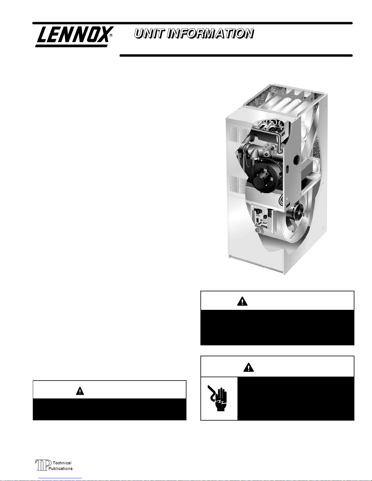
G41UF SERIES UNITS
G41UF series units are high−efficiency upflow gas fur
naces manufactured with Lennox DuralokPlust alumi
nized primary and stainless steel secondary clamshelltype
heat exchangers. G41UF units are available in heating
input capacities of 44,000 to 132,000 Btuh (12.9 to 38.6 kW)
and cooling applications from 2 through 5 tons (7.0 through
17.6 kW). Refer to Engineering Handbook for proper sizing.
Units are factory equipped for use with natural gas. A kit is
available for conversion to LPG operation. All G41UF
units are equipped with the Lennox SureLight® hot sur
face ignition system. The gas valve is redundant to as
sure safety shut−off as required by C.S.A.
The heat exchanger, burners and manifold assembly can be
removed for inspection and service. The maintenance section
gives a detailed description on how this is done.
Information contained in this manual is intended for use by
qualified service technicians only. All specifications are sub
ject to change. Procedures outlined in this manual are pre
sented as a recommendation only and do not supersede or
replace local or state codes.
G41UF
Table of Contents
General 1. . . . . . . . . . . . . . . . . . . . . . . . . . . . . . . . . . . . . .
Specifications 2. . . . . . . . . . . . . . . . . . . . . . . . . . . . . . . . .
Blower Performance Data 3. . . . . . . . . . . . . . . . . . . . . .
I−Unit Components 8. . . . . . . . . . . . . . . . . . . . . . . . . . . .
II −Placement and Installation 16. . . . . . . . . . . . . . . . . . .
III−Start−Up 21. . . . . . . . . . . . . . . . . . . . . . . . . . . . . . . . . . .
IV−Heating System Service Checks 22. . . . . . . . . . . . . .
V−Typical Operating Conditions 26. . . . . . . . . . . . . . . . .
VI−Maintenance 27. . . . . . . . . . . . . . . . . . . . . . . . . . . . . . .
VII−Wiring and Sequence of Operation 30. . . . . . . . . . .
VIII−Troubleshooting 35. . . . . . . . . . . . . . . . . . . . . . . . . . .
CAUTION
As with any mechanical equipment, personal injury
can result from contact with sharp sheet metal
edges. Be careful when you handle this equipment.
WARNING
Improper installation, adjustment, alteration, service
or maintenance can cause property damage, person
al injury or loss of life. Installation and service must
be performed by a qualified installer, service agency
or the gas supplier.
WARNING
Electric shock hazard. Can cause injury
or death. Before attempting to perform
any service or maintenance, turn the
electrical power to unit OFF at discon
nect switch(es). Unit may have multiple
power supplies.
Page 1
2003 Lennox Industries Inc.
Litho U.S.A.
Page 2
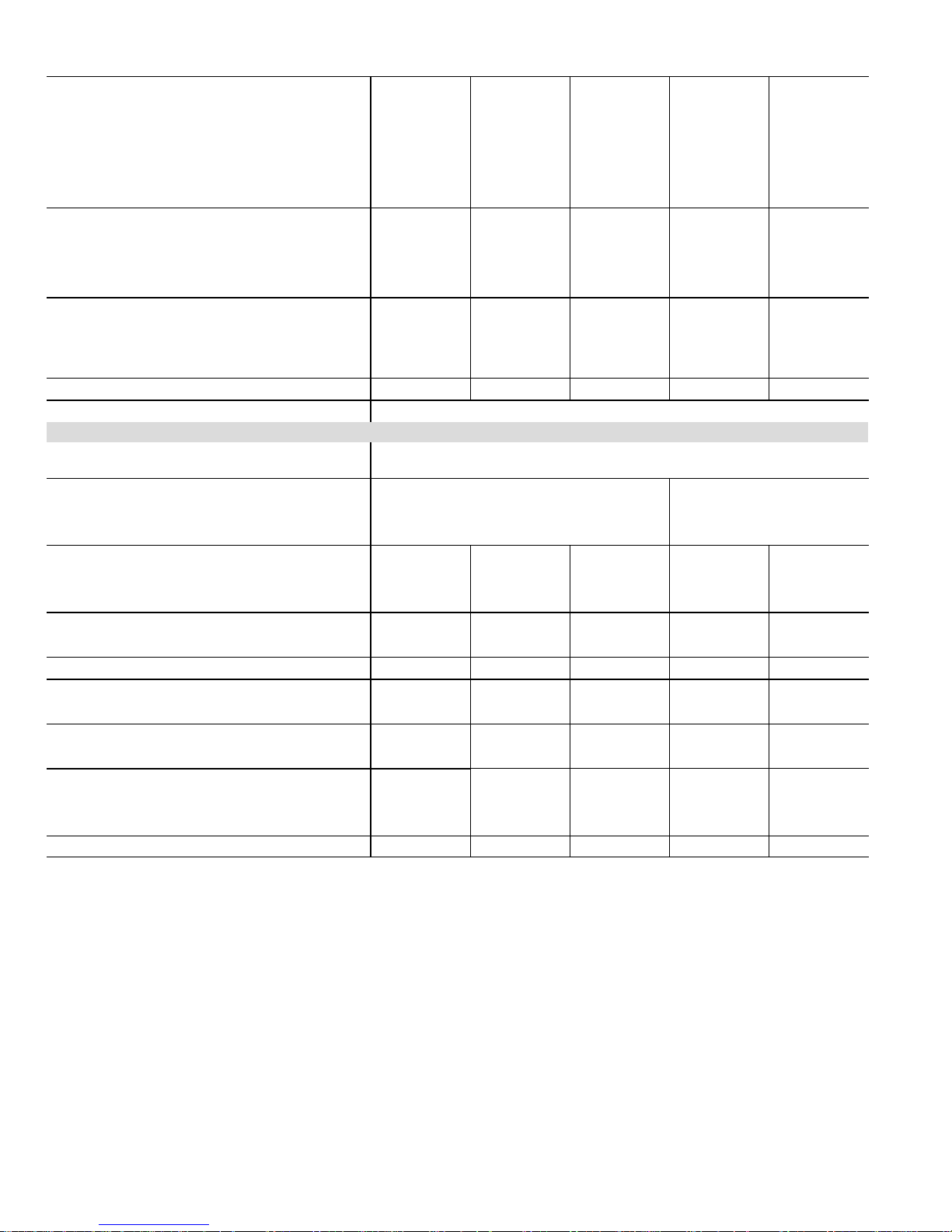
SPECIFICATIONS
Performance
Drain H
T
Ki
Gas
Heating
Performance
Output− Btuh (kW) 40,000 (11.7) 40,000 (11.7) 60,000 (17.6) 80,000 (23.4) 80,000 (23.4)
Highstatic(CSA)− in.w.g. (Pa) 0.5 0.5 0.5 0.5 0.5
Temperature rise range − _F (_C) 35 − 65 (19 − 36) 25 − 55 (14 − 31) 35 − 65 (19 − 36) 50 − 80 (28 − 44) 45 − 75 (25 − 42)
Connections
in. (mm)
Condensate Drain (PVCPipe) − i.d. 1/2 (13)
Exhaust Pipe (PVC) 2 (51) 2 (51) 2 (51) 2 (51) 2 (51)
Condensate Drain (PVC Coupling) − o.d. 3/4 (19) 3/4 (19) 3/4 (19) 3/4 (19) 3/4 (19)
Indoor
Wheel nominal diameter x width −in. (mm)
Blower
Motoroutput − hp (W) 1/5 (149) 1/3 (249) 1/3 (249) 1/3 (249) 1/2 (373)
Tons(kW) ofaddoncooling 1 − 2 (3.5 − 7.0) 1 − 3 (3.5 − 10.5) 1 − 3 (3.5 − 10.5) 1 − 3 (3.5 − 10.5) 2 − 4 (7.0 − 14.0)
Shippingweight − 1 package 128 lbs. (58 kg) 131 lbs. (59 kg) 141 lbs (64 kg) 160 lbs. (73 kg) 164 lbs. (74 kg)
Electricalcharacteristics 120 volts − 60 hertz − 1 phase (less than 12 amps)
OPTIONAL ACCESSORIES – MUST BE ORDERED EXTRA
4
Side Return Air Filter & Rack Kit − Number & size of
filters
EZ Filter
Base
Number and size of field provided filter − in. (mm) 16 x 25 x 1 (406 x 635 x 25) 20 x 25 x 1 (508 x 635 x 25)
Condensate
eat
Cable
Heat Cable
ape
6
High Altitude Orifice Kit − Natural Gas 47M82 47M82 47M82 47M82 47M82
3
High Altitude
Pressure Switch Kit
LPG/Propane Kit
5
Termination
ts
Twinning Kit 15L38 15L38 15L38 15L38 15L38
1
Annual Fuel Utilization Efficiency based on DOE test procedures and according to FTC labeling regulations. Isolated combustion system rating for nonweatherized
furnaces.
3
Required for proper operation at altitudes over 4500 ft. (1370 m).
4
Cleanable polyurethane frame type filter.
5
Kits contain enough parts for two installations. Determine from venting tables proper exhaust pipe size and termination kit required.
6
Required for proper operation at altitudes from 7501 to 10,000 ft. (2286 to 3048 m).
NOTE − Filters and provisions for mounting are not furnished and must be field provided.
Catalog Number − Shipping Weight 73P56 − 7 lbs. (3 kg) 73P57 − 8 lbs. (4 kg)
Dimensions − H x W x D − in. (mm) 4 x 17−5/8 x 28−5/8 (102 x 448 x 727)
50 ft. (15.2 m) long 26K70 26K70 26K70 26K70 26K70
Fiberglass − 1/2 in. (38 mm) x 66 ft. (20 m)
Aluminum foil − 2 in. (25 mm) x 60 ft. (18 m)
4501−7500 ft. (1372−2286 m)
7501−10,000 ft. (2286−3048 m)
0−7500 ft. (0−2286 m) 47M83 47M83 47M83 47M83 47M83
7501−10,000 ft. (2286−3048 m) 47M81 47M81 47M81 47M81 47M81
Roof − 2 inch (51 mm)
Roof − 3 inch (76 mm)
Wall Ring − 2 inch (51 mm) 15F74 15F74 15F74 15F74 15F74
ModelNo. G41UF−24B−045 G41UF−36B−045 G41UF−36B−070 G41UF−36C−090 G41UF−48C−090
Input− Btuh (kW) 44,000 (12.9)
1
AFUE 90.0% 90.0% 90.0% 90.0% 90.0%
44,000 (12.9) 66,000 (19.3) 88,000 (25.8) 88,000 (25.8)
1/2 (13) 1/2 (13) 1/2 (13) 1/2 (13)
GaspipesizeIPS 1/2 (13) 1/2 (13) 1/2 (13) 1/2 (13) 1/2 (13)
10 x 7
(254 x 178)
10 x 8
(254 x 203)
10 x 8
(254 x 203)
10 x 8
(254 x 203)
10 x 10
(254 x 254)
Single 44J22 or Ten Pack 66K63 − (1) 16 x 25 x 1 in. (406 x 635 x 25 mm)
4 x 21−5/8 x 28−5/8 (102 x 549 x 727)
6 ft. (1.8 m) long 26K68 26K68 26K68 26K68 26K68
24 ft. (7.3 m) long 26K69
26K69 26K69 26K69 26K69
39G04 39G04 39G04 39G04 39G04
39G03
39G03 39G03 39G03 39G03
− − − − − − − − − 46M94 46M94
46M94
46M94 46M94 46M94 46M94
15F75 15F75 15F75 15F75 15F75
44J41
44J41 44J41 44J41 44J41
Page 2
Page 3
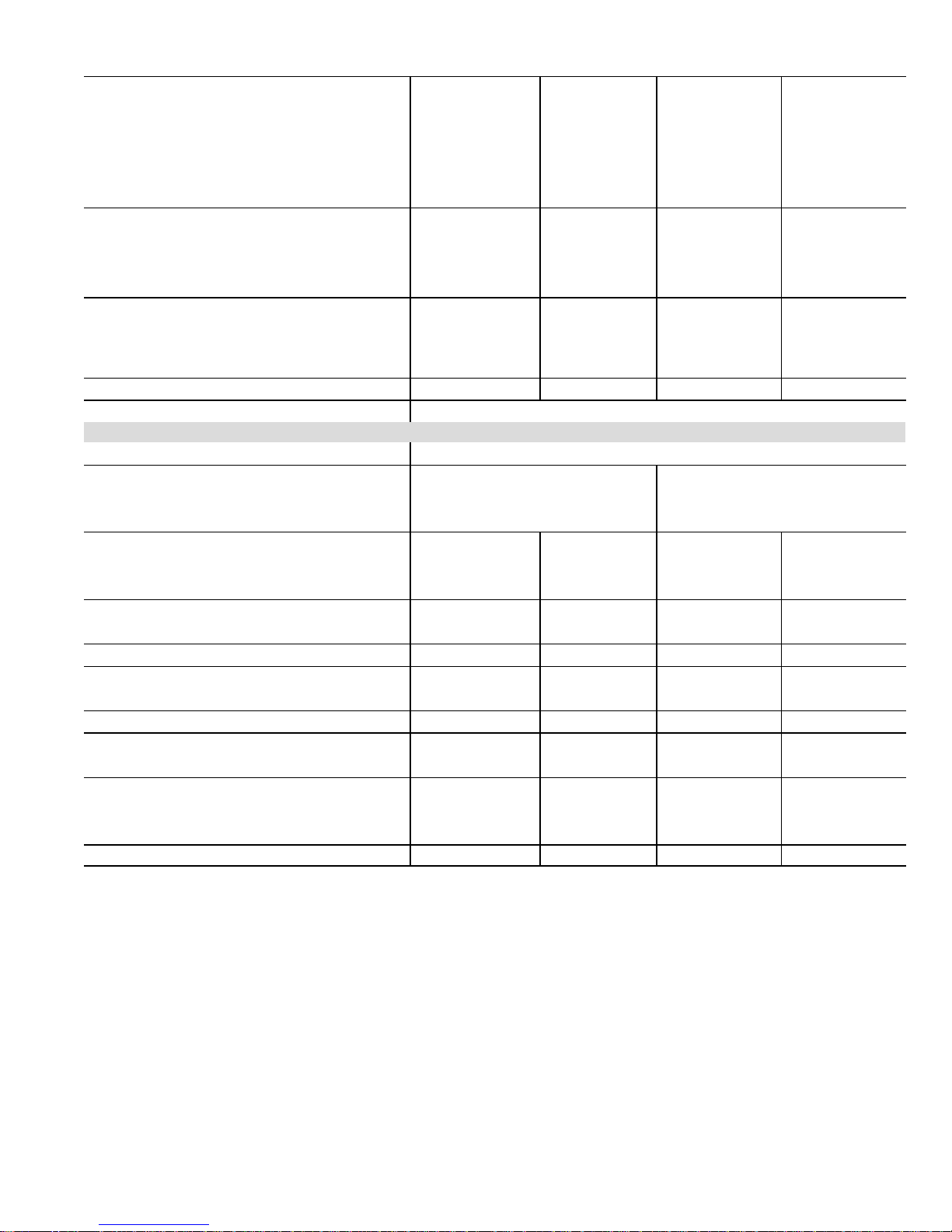
SPECIFICATIONS
Performance
Drain H
T
Ki
Gas
Heating
Performance
Highstatic(CSA)− in.w.g. (Pa) 0.5 0.5 0.5 0.5
Temperature rise range − _F (_C) 25 − 55 (14 − 31) 50 − 80 (28 − 44) 40 − 70 (22 − 39) 45 − 75 (25 − 42)
Connections
in. (mm)
Condensate Drain (PVC Pipe) − i.d. 1/2 (13)
Exhaust Pipe (PVC) 2 (51) 2 (51) 2 (51) 2 (51)
Condensate Drain (PVC Coupling) − o.d. 3/4 (19) 3/4 (19) 3/4 (19) 3/4 (19)
Indoor
Blower
Wheelnominaldiameter xwidth −in. (mm) 11−1/2 x 10 (292 x 229)
Motoroutput − hp (W) 3/4 (560) 1/2 (373) 3/4 (560) 3/4 (560)
Tons(kW) ofaddoncooling 4 − 5 (14.0 − 17.5) 2 − 4 (7.0 − 14.0) 4 − 5 (14.0 − 17.5) 4 − 5 (14.0 − 17.5)
Shippingweight − 1 package 168 lbs. (76 kg) 173 lbs. (78 kg) 177 lbs. (80 kg) 194 lbs. (88 kg)
Electricalcharacteristics 120 volts − 60 hertz − 1 phase (less than 12 amps)
OPTIONAL ACCESSORIES – MUST BE ORDERED EXTRA
4,6
Air Filter and Rack Kit − Number & size of filters Single 44J22 or Ten Pack 66K63 − (1) 16 x 25 x 1 (406 x 635 x 25)
EZ Filter
Base
Condensate
eat
Cable
Heat Cable
ape
7
High Altitude Orifice Kit − Natural Gas Only 47M82 47M82 47M82 47M82
3
High Altitude
Pressure Switch Kit
RAB Return Air Base RAB60C (12M71) − − − − RAB60D (12M72) RAB60D (12M72)
LPG/Propane Kit
5
Termination
ts
Twinning Kit 15L38 15L38 15L38 15L38
1
Annual Fuel Utilization Efficiency based on DOE test procedures and according to FTC labeling regulations. Isolated combustion system rating for nonweatherized
furnaces.
3
Required for proper operation at altitudes over 4500 ft. (1370 m).
4
Cleanable polyurethane frame type filter.
5
Kits contain enough parts for two installations. Determine from venting tables proper exhaust pipe size and termination kit required.
6
Not for use with RAB Return Air Base or with 60C and 60D size units with air flow requirements of 1800 cfm (850 L/s) or greater. See Blower Performance
tables for additional information.
7
Required for proper operation at altitudes from 7501 to 10,000 ft. (2286 to 3048 m).
NOTE − Filters and provisions for mounting are not furnished and must be field provided.
Catalog Number − Shipping Weight 73P57 − 8 lbs. (4 kg) 73P58 − 10 lbs. (5 kg)
Dimensions − H x W x D 4 x 21−5/8 x 28−5/8 in. (102 x 549 x 727 mm)
Number and size of field provided filter 20 x 25 x 1 in. (508 x 635 x 25 mm) 24 x 24 x 1 in. (610 x 610 x 25 mm)
Fiberglass − 1/2 in. (38 mm) x 66 ft. (20 m)
Aluminum foil − 2 in. (25 mm) x 60 ft. (18 m)
4501−7500 ft. (1372−2286 m) 46M94 46M94 46M94 − − −
7501−10,000 ft. (2286−3048m) 46M94
0−7500 ft. (0−2286 m) 47M83 47M83 47M83 47M83
7501−10,000ft. (2286−3048m) 47M81 47M81 47M81 47M81
Roof − 2 inch (51 mm)
Roof − 3 inch (76 mm)
Wall Ring − 2 inch (51 mm) 15F74 15F74 15F74 15F74
ModelNo. G41UF−60C−090 G41UF−48C−110 G41UF−60C−110 G41UF−60D−135
Input− Btuh (kW) 88,000 (25.8)
110,000 (32.2) 110,000 (32.2) 132,000 (38.7)
Output− Btuh (kW) 80,000 (23.4) 100,000 (29.3) 100,000 (29.3) 120,000 (35.1)
1
AFUE 90.0% 90.0% 90.0% 90.0%
1/2 (13) 1/2 (13) 1/2 (13)
GaspipesizeIPS 1/2 (13) 1/2 (13) 1/2 (13) 1/2 (13)
10 x 10 (254 x
254)
11−1/2 x 10 (292 x
229)
11−1/2 x 10 (292 x
229)
4 x 24−5/8 x 28−5/8 in. (102 x 625 x 727 mm)
6 ft. (1.8 m) long 26K68 26K68 26K68 26K68
24 ft. (7.3 m) long 26K69
26K69 26K69 26K69
50 ft. (15.2 m) long 26K70 26K70 26K70 26K70
39G04 39G04 39G04 39G04
39G03
39G03 39G03 39G03
46M94 46M94 46M95
15F75 15F75 15F75 15F75
44J41
44J41 44J41 44J41
Page 3
Page 4
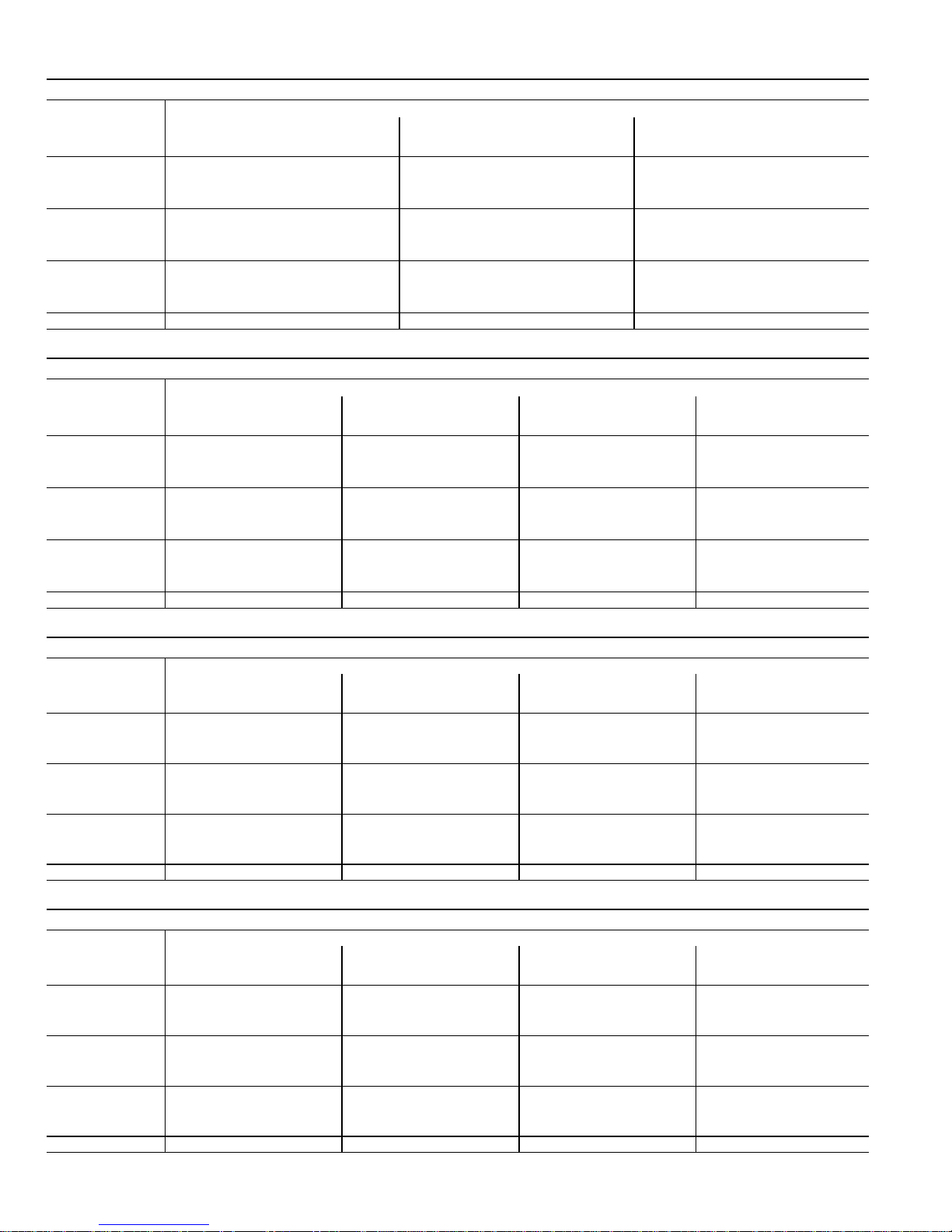
BLOWER PERFORMANCE
External Static
External Static
External Static
External Static
G41UF−24B−045 PERFORMANCE
External Static
Pressure
in. w.g. Pa cfm L/s Watts cfm L/s Watts cfm L/s Watts
0.00
0.10 25 1190 560 455 990 470 355 815 385 275
0.20 50 1160
0.30
0.40 100 1070 505 395 910 430 305 755 355 245
0.50 125 1015
0.60
0.70 175 885 415 335 750 355 260 640 300 210
0.80 200 825
0.90
NOTES − All air data is measured external to unit without filter (not furnished − field provided).
0 1225 580 485 1000 470 365 820 385 290
75 1120 530 415 945 445 325 780 365 260
150 955 450 355 835 395 285 695 325 225
225 715 335 3000 600 285 220 435 205 170
Air volume based on bottom air return air. Actual air volume may vary on side return air applications.
High
545 435 970 460 340 805 380 265
480 375 865 405 295 740 350 240
390 320 695 330 245 545 255 185
G41UF−36B−045 PERFORMANCE
External Static
Pressure
in. w.g. Pa cfm L/s Watts cfm L/s Watts cfm L/s Watts cfm L/s Watts
0.00
0.10 25 1515 715 605 1385 655 555 1190 560 485 1020 480 415
0.20 50 1470
0.30
0.40 100 1350 640 535 1250 590 465 1120 530 410 980 465 360
0.50 125 1290
0.60
0.70 175 1145 540 460 1080 510 400 975 460 345 860 405 300
0.80 200 1050
0.90
NOTES − All air data is measured external to unit without filter (not furnished − field provided).
25 1555 735 630 1410 665 585 1190 560 520 1030 485 435
75 1410 665 555 1310 620 495 1155 545 440 1000 470 385
150 1220 575 485 1145 540 420 1020 480 365 905 430 320
225 945 445 410 900 425 345 825 390 305 730 345 270
Air volume based on bottom air return air. Actual air volume may vary on side return air applications.
High
695 580 1345 635 520 1170 550 455 1010 475 400
610 505 1205 570 450 1080 510 390 950 450 345
495 425 985 465 365 870 410 320 785 370 285
G41UF−36B−070 PERFORMANCE
External Static
Pressure
in. w.g. Pa cfm L/s Watts cfm L/s Watts cfm L/s Watts cfm L/s Watts
0.00
0.10 25 1600 755 635 1395 660 550 1160 545 460 1000 470 385
0.20 50 1540
0.30
0.40 100 1420 670 545 1275 605 480 1125 530 395 965 455 345
0.50 125 1360
0.60
0.70 175 1170 555 465 1085 515 385 965 430 335 860 405 295
0.80 200 1080
0.90
NOTES − All air data is measured external to unit without filter (not furnished − field provided).
0 1640 775 660 1415 665 575 1160 545 485 1005 475 410
75 1495 705 580 1345 635 505 1145 540 425 990 465 365
150 1275 600 490 1165 550 410 1025 485 350 900 425 305
225 945 445 400 840 395 320 765 360 275 710 335 245
Air volume based on bottom air return air. Actual air volume may vary on side return air applications.
High
725 605 1370 650 525 1160 545 445 995 470 375
640 525 1245 590 450 1080 510 375 945 445 325
510 440 1010 475 360 865 410 310 775 365 270
G41UF−36C−090 PERFORMANCE
External Static
Pressure
in. w.g. Pa cfm L/s Watts cfm L/s Watts cfm L/s Watts cfm L/s Watts
0.00
0.10 25 1680 795 700 1390 650 585 1185 560 480 1005 475 395
0.20 50 1645
0.30
0.40 100 1560 735 615 1345 635 515 1155 545 425 990 465 360
0.50 125 1495
0.60
0.70 175 1330 630 505 1205 570 435 1035 490 360 890 420 300
0.80 200 1255
0.90
NOTES − All air data is measured external to unit without filter (not furnished − field provided).
0 1705 805 730 1395 660 605 1195 555 495 1010 475 410
75 1600 755 635 1365 645 535 1165 550 445 995 470 375
150 1415 665 540 1270 600 475 1080 510 375 940 445 320
225 1135 535 450 1020 480 365 830 390 300 760 360 260
Air volume based on bottom air return air. Actual air volume may vary on side return air applications.
High
775 675 1380 650 560 1175 555 465 1000 470 390
705 580 1305 615 500 1125 530 400 970 460 345
590 485 1120 530 400 955 450 330 840 395 280
Air Volume / Watts at Different Blower Speeds
Medium Low
Air Volume / Watts at Different Blower Speeds
Medium−High Medium−Low Low
Air Volume / Watts at Different Blower Speeds
Medium−High Medium−Low Low
Air Volume / Watts at Different Blower Speeds
Medium−High Medium−Low Low
Page 4
Page 5
BLOWER PERFORMANCE
External Static
External Static
External Static
External Static
G41UF−48C−090 PERFORMANCE
External Static
Pressure
in. w.g. Pa cfm L/s Watts cfm L/s Watts cfm L/s Watts cfm L/s Watts
0.00
0.10 25 2135 1005 885 1825 860 750 1510 710 610 1275 600 495
0.20 50 2085
0.30
0.40 100 1940 915 760 1735 820 650 1480 700 535 1250 590 440
0.50 125 1865
0.60
0.70 175 1645 775 640 1475 695 520 1290 610 450 1105 520 375
0.80 200 1540
0.90
NOTES − All air data is measured external to unit without filter (not furnished − field provided).
0 2180 1030 930 1835 865 790 1520 715 630 1280 605 510
75 2030 955 800 1775 835 685 1500 705 565 1265 595 460
150 1740 820 670 1590 750 575 1380 650 475 1175 555 410
225 1335 630 540 1170 555 440 1070 505 375 950 450 330
Air volume based on bottom air return air. Actual air volume may vary on side return air applications.
High
985 840 1810 855 720 1505 710 580 1270 600 475
880 725 1660 785 600 1430 675 505 1215 575 425
725 600 1340 630 465 1175 555 405 1020 480 355
G41UF−60C−090 PERFORMANCE − Single Side Return Air − Air volumes in bold require field fabricated transition to ac
commodate 20 x 25 x 1 in. (508 x 635 x 25 mm) cleanable air filter in order to maintain proper air velocity.
External Static
Pressure
in. w.g. Pa cfm L/s Watts cfm L/s Watts cfm L/s Watts cfm L/s Watts
0.00
0.10 25 2460 1160 1145 2310 1090 970 2095 990 825 1780 840 660
0.20 50 2395
0.30
0.40 100 2225 1050 1050 2110 995 880 1950 920 745 1720 810 620
0.50 125 2135
0.60
0.70 175 1950 920 950 1865 880 790 1750 825 675 1535 725 555
0.80 200 1845
0.90
NOTES − All air data is measured external to unit without filter (not furnished − field provided).
0 2510 1185 1160 2350 1110 990 2145 1010 850 1785 845 670
75 2325 1095 1090 2175 1025 910 2015 950 775 1735 820 630
150 2025 955 975 1950 920 820 1820 860 700 1600 755 575
225 1730 815 885 1640 775 720 1555 735 625 1340 630 510
High Medium−High Medium−Low Low
1130 1125 2240 1060 940 2060 970 805 1760 830 650
1010 1015 2050 965 855 1900 895 725 1665 785 600
870 915 1760 830 755 1640 775 650 1450 685 530
G41UF−60C−090 PERFORMANCE − Bottom Return Air, Side Return Air with Optional RAB Return Air Base, Return Air from
Both Sides or Return Air from Bottom and One Side.
External Static
Pressure
in. w.g. Pa cfm L/s Watts cfm L/s Watts cfm L/s Watts cfm L/s Watts
0.00
0.10 25 2525 1195 1210 2320 1095 1010 2040 960 855 1775 835 710
0.20 50 2450
0.30
0.40 100 2300 1085 1125 2155 1020 930 1970 930 800 1720 815 665
0.50 125 2210
0.60
0.70 175 2080 980 1035 1975 935 865 1805 855 730 1610 760 615
0.80 200 2000
0.90
NOTES − All air data is measured external to unit without filter (not furnished − field provided).
0 2575 1215 1235 2360 111 5 1030 2050 965 875 1790 845 720
75 2375 1120 1140 2215 1045 955 1995 940 815 1740 820 680
150 2140 1010 1030 2055 970 895 1875 885 755 1665 785 635
225 1905 900 970 1785 845 800 1640 775 675 1495 705 570
High
1155 1170 2270 1070 985 2025 955 840 1755 830 695
1045 1075 2090 985 900 1915 905 775 1700 800 650
945 1010 1890 890 830 1730 815 705 1565 740 595
G41UF−48C−110 PERFORMANCE
External Static
Pressure
in. w.g. Pa cfm L/s Watts cfm L/s Watts cfm L/s Watts cfm L/s Watts
0.00 0 2160 1020 880 1880 890 755 1490 705 602 1235 580 485
0.10 25 2100 990 850 1855 875 730 1480 700 585 1230 580 475
0.20 50 2035 960 805 1815 860 690 1475 695 560 1225 580 460
0.30
0.40 100 1885 890 725 1715 810 625 1465 690 510 1215 575 430
0.50 125 1780
0.60
0.70 175 1575 745 620 1410 665 505 1210 570 405 1035 490 350
0.80 200 1375
0.90
NOTES − All air data is measured external to unit without filter (not furnished − field provided).
75 1965 925 750 1755 830 650 1475 695 545 1220 575 445
150 1690 800 660 1550 735 550 1360 640 460 111 0 525 380
225 1225 580 520 1120 530 415 1050 495 365 885 420 310
Air volume based on bottom air return air. Actual air volume may vary on side return air applications.
High
840 680 1630 770 580 1420 670 490 1150 540 400
650 550 1230 580 450 1125 530 380 970 460 325
Air Volume / Watts at Different Blower Speeds
Medium−High Medium−Low Low
Air Volume / Watts at Different Blower Speeds
Air Volume / Watts at Different Blower Speeds
Medium−High Medium−Low Low
Air Volume / Watts at Different Blower Speeds
Medium−High Medium−Low Low
Page 5
Page 6
BLOWER PERFORMANCE
External Static
External Static
External Static
External Static
G41UF−60C−110 PERFORMANCE − Single Side Return Air − Air volumes in bold require field fabricated transition to ac
commodate 20 x 25 x 1 in. (508 x 635 x 25 mm) cleanable air filter in order to maintain proper air velocity.
External Static
Pressure
in. w.g. Pa cfm L/s Watts cfm L/s Watts cfm L/s Watts cfm L/s Watts
0.00
0.10 25 2500 1180 1270 2280 1075 1050 2025 950 855 1730 815 720
0.20 50 2410
0.30
0.40 100 2280 1075 1170 2115 995 940 1910 900 790 1675 790 680
0.50 125 2195
0.60
0.70 175 1980 935 1030 1860 880 845 1705 805 700 1540 725 605
0.80 200 1895
0.90
NOTES − All air data is measured external to unit without filter (not furnished − field provided).
0 2550 1205 1300 2345 1105 1080 2055 970 895 1740 820 715
75 2350 111 0 1190 2175 1025 965 1945 920 805 1690 795 670
150 2075 980 1065 1955 925 875 1785 845 735 1585 750 630
225 1770 835 975 1640 775 770 1535 725 645 1415 670 565
High
1140 1225 2220 1050 1000 2000 945 840 1715 810 695
1035 1115 2035 960 910 1840 870 760 1630 770 650
895 1005 1770 835 810 1615 765 675 1475 695 580
G41UF−60C−110 PERFORMANCE − Bottom Return Air, Side Return Air with Optional RAB Return Air Base, Return Air from
Both Sides or Return Air from Bottom and One Side.
External Static
Pressure
in. w.g. Pa cfm L/s Watts cfm L/s Watts cfm L/s Watts cfm L/s Watts
0.00
0.10 25 2515 1190 1295 2295 1085 1075 2040 960 880 1740 820 745
0.20 50 2450
0.30
0.40 100 2310 1090 1190 2145 1010 975 1925 910 815 1690 800 695
0.50 125 2200
0.60
0.70 175 2045 965 1065 1930 910 890 1750 825 730 1575 745 625
0.80 200 1930
0.90
NOTES − All air data is measured external to unit without filter (not furnished − field provided).
0 2580 1215 1340 2330 1100 1100 2045 965 950 1760 830 745
75 2375 1120 1225 2200 1040 1015 1965 925 835 1715 810 710
150 2130 1005 1105 2025 955 930 1825 860 770 1600 755 650
225 1820 860 980 1730 815 815 1555 735 660 1430 675 580
High
1155 1255 2255 1065 1040 2005 945 855 1735 820 730
1040 1135 2085 985 955 1870 880 780 1660 785 670
910 1025 1825 860 850 1650 780 695 1500 710 600
G41UF−60D−135 PERFORMANCE − Single Side Return Air − Air volumes in bold require field fabricated transition to ac
commodate 20 x 25 x 1 in. (508 x 635 x 25 mm) cleanable air filter in order to maintain proper air velocity.
External Static
Pressure
in. w.g. Pa cfm L/s Watts cfm L/s Watts cfm L/s Watts cfm L/s Watts
0.00
0.10 25 2490 1175 1305 2275 1075 1100 2025 955 900 1720 810 755
0.20 50 2430
0.30
0.40 100 2285 1080 1210 2140 1010 1010 1910 900 830 1680 790 700
0.50 125 2200
0.60
0.70 175 2010 950 1075 1915 905 910 1740 820 740 1545 730 630
0.80 200 1910
0.90
NOTES − All air data is measured external to unit without filter (not furnished − field provided).
0 2550 1205 1340 2330 1100 1145 2035 960 955 1725 815 775
75 2355 111 0 1235 2180 1030 1035 1955 920 855 1700 800 715
150 2100 990 1110 1985 935 935 1815 855 780 1600 755 660
225 1815 855 1005 1735 820 835 1605 755 690 1420 670 580
High
1145 1285 2230 1050 1065 1990 940 890 1715 810 740
1040 1160 2070 975 980 1865 880 805 1645 775 675
900 1050 1845 870 875 1670 790 720 1490 705 605
G41UF−60D−135 PERFORMANCE − Bottom Return Air, Side Return Air with Optional RAB Return Air Base, Return Air from
Both Sides or Return Air from Bottom and One Side.
External Static
Pressure
in. w.g. Pa cfm L/s Watts cfm L/s Watts cfm L/s Watts cfm L/s Watts
0.00
0.10 25 2530 1195 1335 2330 1100 1120 2075 980 945 1730 820 750
0.20 50 2475
0.30
0.40 100 2355 1110 1230 2185 1030 1040 1975 930 865 1680 795 695
0.50 125 2275
0.60
0.70 175 2100 990 1125 1955 925 930 1785 840 780 1550 730 635
0.80 200 1995
0.90
NOTES − All air data is measured external to unit without filter (not furnished − field provided).
0 2585 1220 1370 2355 111 0 1160 2075 980 985 1730 820 765
75 2410 1135 1260 2230 1050 1060 2010 950 890 1715 810 725
150 2190 1035 1155 2045 965 960 1850 875 805 1615 765 660
225 1860 880 1020 1750 825 835 1635 770 720 1425 670 580
High
1170 1300 2295 1085 1090 2050 970 920 1730 815 745
1075 1190 2120 1000 995 1915 905 830 1650 780 685
945 1080 1855 875 890 1715 810 745 1500 710 615
Air Volume / Watts at Different Blower Speeds
Medium−High Medium−Low Low
Air Volume / Watts at Different Blower Speeds
Medium−High Medium−Low Low
Air Volume / Watts at Different Blower Speeds
Medium−High Medium−Low Low
Air Volume / Watts at Different Blower Speeds
Medium−High Medium−Low Low
Page 6
Page 7
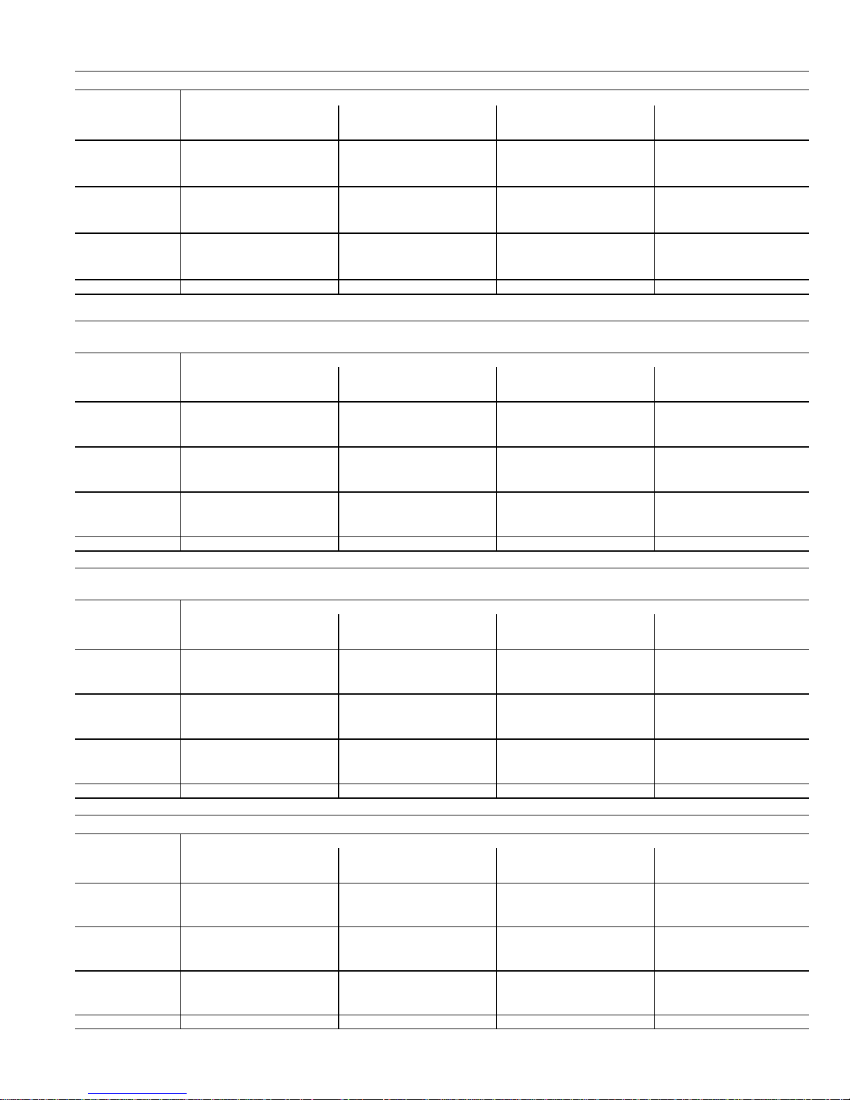
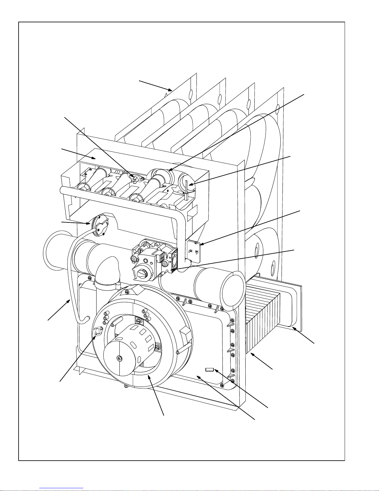
G41UF PARTS IDENTIFICATION
BURNER BOX
ASSEMBLY
GAS VALVE AND
MANIFOLD
COMBUSTION AIR
PROVE
(PRESSURE)
SWITCH
FLUE
COLLAR
COMBUSTION AIR
INDUCER
DuralokPlus
HEAT EXCHANGER
ASSEMBLY
TM
TOP CAP
CABINET
WARM HEADER
(COLLECTOR)
BOX
BURNER
ACCESS
PANEL
BLOWER
ACCESS
DOOR
SIGHT
GLASS
DOOR
INTERLOCK
SWITCH
CONTROL BOX
CONDENSER COIL
PRIMARY LIMIT
COLD HEADER
(COLLECTOR)
BOX
FIGURE 1
Page 7
Page 8
I−UNIT COMPONENTS
G41UF unit components are shown in figure 1. The com
bustion air inducer, gas valve and burners can be accessed
by removing the burner access panel. The blower and con
trol box can be accessed by removing the blower access
door. G41UF units are designed for bottom and side re
turn air.
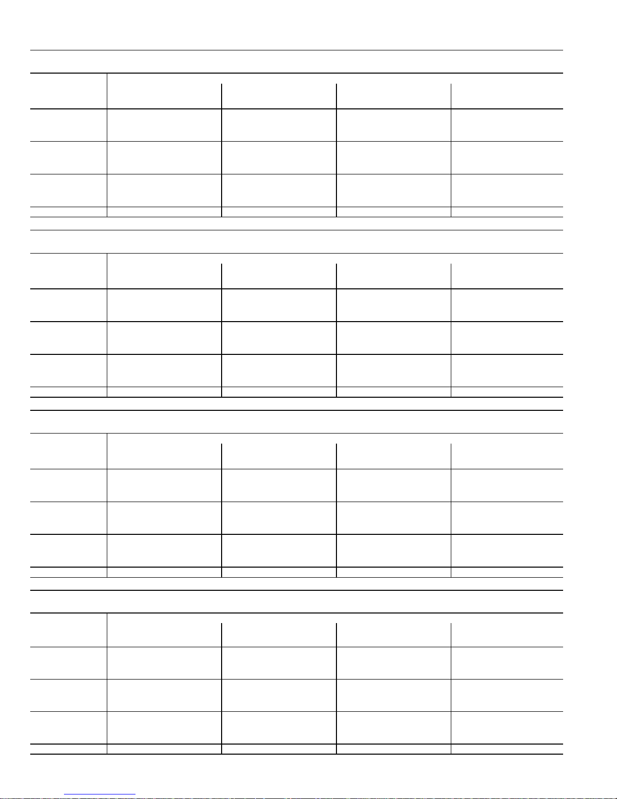
A−MakeUp Box (Figure 2)
A field makeup box is provided for line voltage wiring. Line
voltage wiring to unit is routed from the make up box. The
hot" wire is connected to the door switch and then from the
switch to the SureLight board. The make−up box may be
installed inside or outside the unit and on the unit left or right
side (right side shown figure 2).
INTERIOR MAKE−UP BOX INSTALLATION
MAKE−UP
BOX
Right Side
CLAMP LOCATION
FIGURE 2
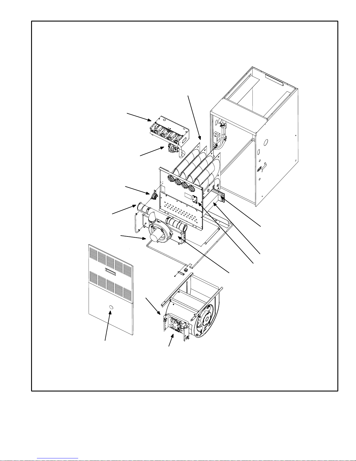
B−Control Box Components (Figure 3)
Unit transformer (T1) and SureLight control (A92) are lo
cated in the control box. In addition, a door interlock switch
(S51) is located in the control box.
DOOR INTERLOCK
SWITCH (S51)
1. Control Transformer (T1)
A transformer located in the control box provides power to
the low voltage 24 volt section of the unit. Transformers on
all models are rated 40VA with a 120V primary and a 24V
secondary.
2. Door Interlock Switch (S51)
A door interlock switch rated 14A at 120VAC is located on
the control box. The switch is wired in series with line volt
age. When the blower door is removed the unit will shut
down.
WARNING
Shock hazard.
Disconnect power before servicing. Control is
not field repairable. If control is inoperable, sim
ply replace entire control.
Can cause injury or death. Unsafe operation will
result if repair is attempted.
3. Furnace Control (A92)
All G41UF model units are equipped with the Lennox Sur
eLight ignition system. The system consists of ignition
control board (figure 5 with control terminal designations
in table 3), ignitor (figure 6) and sensor (figure 7). The
board and ignitor work in combination to ensure furnace
ignition and ignitor durability. The SureLight integrated
board controls all major furnace operations. The board
also features two LED lights for troubleshooting and two
accessory terminals rated at (1) one amp. Tables 1 and 2
show jack plug terminal designations. See table 4 for trou
bleshooting diagnostic codes. The SureLight ignitor is
made of durable silicon−nitride. Ignitor longevity is also
enhanced by voltage ramping by the control board. The
board finds the lowest ignitor temperature which will suc
cessfully light the burner, thus increasing the life of the ig
nitor.
ELECTROSTATIC DISCHARGE (ESD)
Precautions and Procedures
CAUTION
SURELIGHT
CONTROL
BOARD
(A92)
FIGURE 3
TRANSFORMER
(T1)
Electrostatic discharge can affect electronic
components. Take precautions during furnace
installation and service to protect the furnace’s
electronic controls. Precautions will help to avoid
control exposure to electrostatic discharge by
putting the furnace, the control and the techni
cian at the same electrostatic potential. Neutral
ize electrostatic charge by touching hand and all
tools on an unpainted unit surface, such as the
gas valve or blower deck, before performing any
service procedure.
Page 8
Page 9

TABLE 1
SureLight BOARD J156 (J2) TERMINAL
DESIGNATIONS
PIN # FUNCTION
1 Combustion Air Inducer Line
2
3
Combustion Air Inducer Neutral
4
Ignitor Line
Ignitor Neutral
TABLE 2
SureLight BOARD J58 (J1) TERMINAL
DESIGNATIONS
PIN # FUNCTION
1 High Limit Output
2
3
4
5
6
7
8
9
10
11
12
Not Used
24V Line
Not Used
Rollout Switch In
24V Neutral
High Limit Input
Ground
Gas Valve In
Pressure Switch Out
Rollout Switch Out
Gas Valve Out
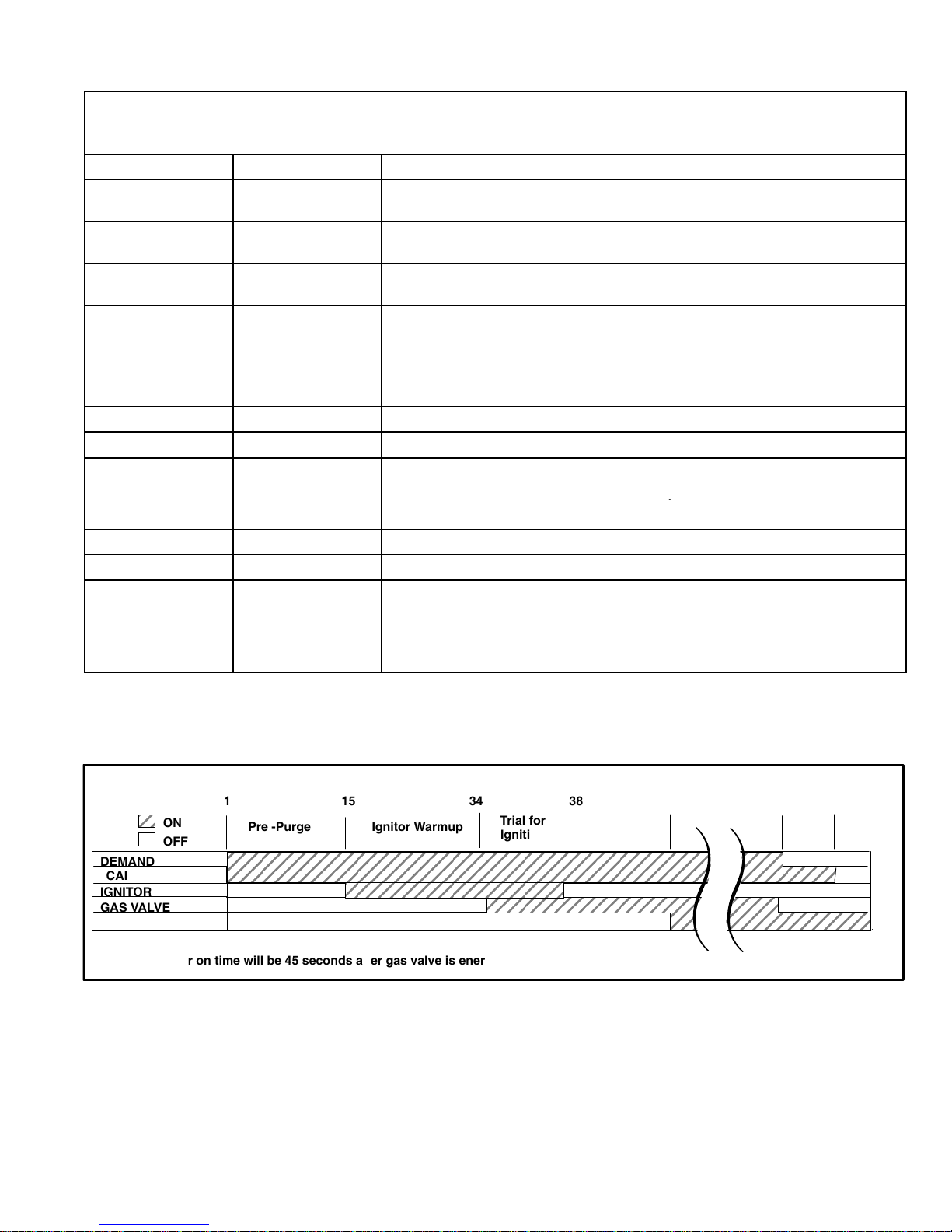
a−Electronic Ignition (See Figure 8)
On a call for heat the SureLight control monitors the com
bustion air inducer prove switch. The control will not begin
the heating cycle if the prove switch is closed (by−passed).
Once the prove switch is determined to be open, the com
bustion air inducer is energized. When the differential in the
prove switch is great enough, the prove switch closes and a
15−second pre−purge begins. If the prove switch is not
proven within 2−1/2 minutes, the control goes into Watch
guard−Pressure Switch mode for a 5−minute re−set period.
After the 15−second pre−purge period, the SureLight ignitor
warms up for 20 seconds during which the gas valve opens
at 19 seconds for a 4−second trial for ignition. The ignitor
stays energized during the 4 second trial until flame is
sensed. If ignition is not proved during the 4−second period,
the control will try four more times with an inter purge and
warm−up time between trials of 35 seconds. After a total of
five trials for ignition (including the initial trial), the control
goes into Watchguard−Flame Failure mode. After a 60−min
ute reset period, the control will begin the ignition sequence
again.
The SureLight control board has an added feature that pro
longs the life of the ignitor. After a successful ignition, the
SureLight control utilizes less power to energize the ignitor
on successive calls for heat. The control continues to ramp
down the voltage to the ignitor until it finds the lowest
amount of power that will provide a successful ignition. This
amount of power is used for 255 cycles. On the 256th call
for heat, the control will again ramp down until the lowest
power is determined and the cycle begins again. Each time
120V is removed and then re−applied, the control re−starts
the learning process.
b−Fan Time Control
The fan on time of 45 seconds is not adjustable. Fan off
time (time that the blower operates after the heat demand
has been satisfied) can be adjusted by setting the dip
switches located on the SureLight integrated control. The
unit is shipped with a factory fan off setting of 90 seconds.
For customized comfort, monitor the supply air tempera
ture once the heat demand is satisfied. Note the supply air
temperature at the instant the blower is de−energized. Ad
just the fan−off delay to achieve a supply air temperature
between 90° − 110° at the instant the blower is de−ener
gized. (Longer delay times allow for lower air temperature,
shorter delay times allow for higher air temperature). See
figure 4.
FANOFF TIME ADJUSTMENT
60sec. 90sec.
OFF
ON
1
2
OFF
ON
OFF
1
2
(Black square indicates switch position)
To adjust fan−off timing, flip dip switch to desired setting.
120sec.
OFFOFF OFF
ON
OFF
180sec.
1
OFF
2
ON
1
2
FIGURE 4
Page 9
Page 10
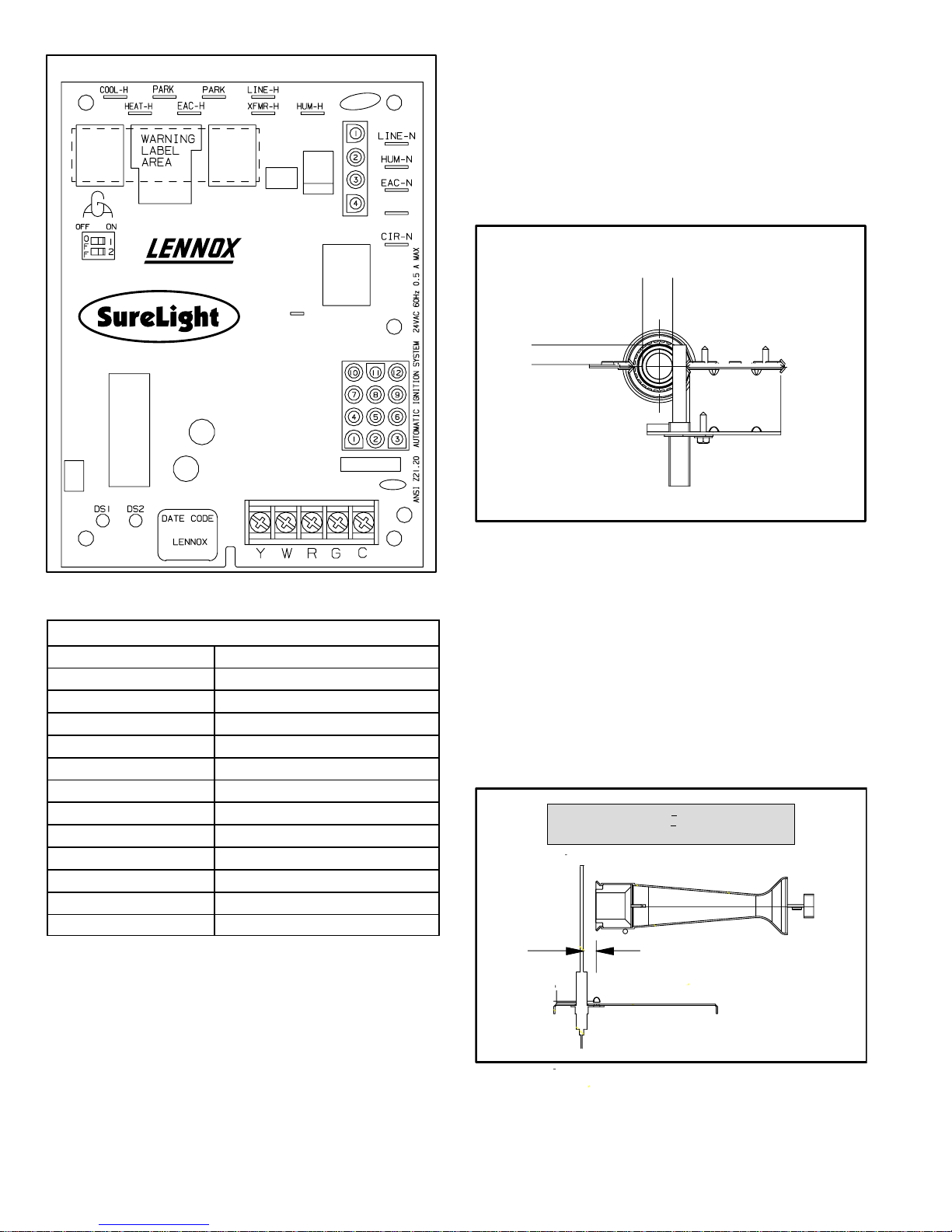
SURELIGHT INTEGRATED CONTROL BOARD
XFMR–N
J156
4. Ignitor (Figure 6)
The SureLight ignitor is made of durable silicon nitride. Ig
nitor longevity is enhanced by controlling voltage to the ig
nitor. The board finds the lowest ignitor temperature which
will successfully light the burner, thus increasing the life of
the ignitor. Due to this feature of the board, voltage cannot
be measured so ignitor must be ohmed. Ohm value should
be 10.9 to 19.7
SureLight Ignitor Location
MEASUREMENT IS TO I.D.
5/8"
OF RETENTION RING
13/32’
J58
FIGURE 5
TABLE 3
TERMINAL DESIGNATIONS
COOL−H 120V HOT Blower Cooling Speed (120VAC)
HEAT−H Blower Heating Speed−(120VAC)
EAC−H Electronic Air Cleaner (120VAC)
HUM−H Humidifier (120VAC)
XFMR−H Transformer (120VAC)
LINE−H Input (120VAC)
LINE−N 120V NEUT Input (Neutral)
HUM−N Humidifier (Neutral)
EAC−N Electronic Air Cleaner (Neutral)
XFMR−N Transformer (Neutral)
CIR−N Blower (Neutral)
PARK Alternate Blower Speeds (dead)
(FLAME SENSE) Flame Sensor
BRACKET
IGNITOR
BURNERS FRONT VIEW
FIGURE 6
5. Flame Sensor (Figure 7)
A flame sensor is located on the left side of the burner sup
port. The sensor is mounted on the bottom burner box plate
and the tip protrudes into the flame envelope of the left−
most burner. The sensor can be removed for service with
out removing any part of the burners. During operation,
flame is sensed by current passed through the flame and
sensing electrode. The SureLight control allows the gas
valve to remain open as long as flame signal is sensed.
NOTE − The G41UF furnace contains electronic com
ponents that are polarity sensitive. Make sure that the
furnace is wired correctly and is properly grounded.
NORMAL FLAME SIGNAL > 0.18 MICROAMPS
LOW FLAME SIGNAL <
DROP OUT SIGNAL = 0.15 MICROAMPS
5/16"
0.17 MICROAMPS
FIGURE 7
Page 10
Page 11
The SureLight board is equipped with two LED lights for troubleshooting. The diagnostic codes are listed below in table 4.
y
TABLE 4
DIAGNOSTIC CODES
Make sure to Identify LED’S Correctly.
Refer to Installation Instructions for control board layout.
LED #1 LED #2 DESCRIPTION
SIMULTANEOUS
SLOW FLASH
SIMULTANEOUS
FAST FLASH
SLOW FLASH ON
OFF SLOW FLASH
ALTERNATING
SLOW FLASH
SLOW FLASH OFF Flame sensed without gas valve energized.
ON SLOW FLASH Rollout switch open. OR: 12pin connector improperly attached.
ON ON
ON OFF
OFF ON
FAST FLASH SLOW FLASH Main power polarity reversed. Switch line and neutral.
SLOW FLASH FAST FLASH Low flame signal. Measures below 0.18 microamps. Replace flame sense rod.
ALTERNATING
FAST FLASH
SIMULTANEOUS
SLOW FLASH
SIMULTANEOUS
FAST FLASH
ALTERNATING
SLOW FLASH
ALTERNATING
FAST FLASH
Power on − Normal operation.
Also signaled during cooling and continuous fan.
Normal operation − signaled when heating demand initiated at thermostat.
Primary or secondary limit switch open. Limit must close within 3 minutes or unit
goes into 1 hour Watchgurad.
Prove switch open.
OR:Blocked inlet/exhaust vent;
OR: Prove switch closed prior to activation of combustion air inducer.
Watchguard −− burners failed to ignite.
Circuit board failure or control wired incorrectly.
The following conditions are sensed during the ignitor warm−up period only:
1) Improper main ground;
2) Broken ignitor; OR: Open ignitor circuit;
3) Line voltage to control below 75 volts.
NOTE − Slow flash rate equals 1 Hz (one flash per second). Fast flash rate equals 3 Hz (three flashes per second).
Low flame sense current = 0.16−0.17 microAmps.
ON
OFF
DEMAND
CAI
IGNITOR
GAS VALVE
INDOOR BLOWER
*Blower on time will be 45 seconds after gas valve is energized. Blower off time will depend on OFF TIME" Setting.
1
Pre −Purge Ignitor Warmup
15
34
Trial for
Ignition
38
Blower On"
Delay
5 SEC80
Post
Purge
FIGURE 8
Page 11
Page 12
ROLLOUT SWITCH
BURNER BOX
ASSEMBLY
G41UF HEATING COMPONENTS
LENNOX DURALOKPlust
HEAT EXCHANGER
(Assembly)
CLAMSHELL
(Each Segment)
CORBEL CUP
SURELIGHT
IGNITOR
LIMIT CONTROL
PROVE SWITCH
PROVE SWITCH
TUBING
BACKUP SECONDARY
LIMIT
GAS VALVE
WARM END HEADER BOX
CONDENSER COIL
COLD END HEADER BOX
ORIFICE SIZE WINDOW
COMBUSTION AIR INDUCER
COLD END HEADER BOX
FIGURE 9
Page 12
Page 13

C−Heating Components (Figure 9)
Combustion air inducer (B6), primary limit control (S10),
SureLight ignitor, burners, flame rollout switch (S47), gas
valve (GV1), combustion air prove switch (S18), and clam
shell heat exchangers are located in the heating compart
ment. The heating compartment can be accessed by re
moving the burner access panel.
1. Combustion Air Inducer (B6)
All G41UF units use a combustion air inducer to move air
through the burners and heat exchanger during heating op
eration. The inducer uses a 120VAC motor. The motor oper
ates during all heating operation and is controlled by burner
ignition control A92. The inducer operates continuously while
there is a call for heat. The ignition control is prevented from
proceeding through the ignition sequence until combustion
air inducer operation is sensed by the prove switch.
The prove switch connected to the plastic cold end header
box is used to prove combustion air inducer operation. The
switch monitors air pressure in the channel of the cold end
header box. During normal operation, the pressure in the
header box is negative. If the pressure drops (becomes more
positive), the pressure switch opens. When the prove switch
opens, the ignition control (A92) immediately closes the gas
valve to prevent burner operation.
2. Primary Limit Control (S10)
Figure 10 shows the primary limit (S10) used on G41UF units.
S10 is located on the heating vestibule panel. When excess
heat is sensed in the heat exchanger, the limit will open. Once
the limit opens, the furnace control energizes the supply air
blower and de−energizes the gas valve. The limit automati
cally resets when unit temperature returns to normal. The
switch is factory set and cannot be adjusted. The switch
has a different setpoint for each unit model number. See
Lennox Repair Parts handbook for set point.
LIMIT CONTROL (S10)
SPADE CONNECTORS
INSULATING COVER (s)
FIGURE 10
4. Burners / Gas Orifices (Figure 11)
All units use inshot burners. Burners are factory set and do not
require adjustment. Burners can be removed as an assembly
for service. Burner maintenance and service is detailed in the
MAINTENANCE section of this manual. Each burner uses
an orifice which is precisely matched to the burner input. For
natural gas units the orifice size is .089" and for L.P. units
.055". This size orifice is good for installation up to 7500’ (for
higher altitudes see table10). The orifice is threaded into the
burner manifold. The burner is supported by the orifice and
will easily slide off for service. Each orifice and burner are
sized specifically to the unit. A flame retention ring in the end
of each burner maintains correct flame length and shape and
keeps the flame from lifting off the burner head. In addition, the
burner entrance to each clamshell (Figure 9) is fitted with a
corbel cup (orifice) used to direct the flow of combustion prod
ucts.
NOTE − Do not use threadsealing compound on the ori
fices. Threadsealing compound may plug the orifices.
5. Clamshell Heat Exchanger
G41UF units use an aluminized steel primary and stain
less steel secondary heat exchanger assembly. Table 5
shows how many heat exchanger clamshells are used
per unit. Heat is transferred to the air stream from all sur
faces of the heat exchanger. The shape of the heat ex
changer ensures maximum efficiency.
The combustion air inducer pulls fresh air through the air
intake box. This air is mixed with gas in the burner venturi
and at the corbel orifices. The gas / air mixture is then
burned at the entrance of each clamshell. Combustion
gases are then pulled through the primary and secondary heat
exchangers and exhausted out the exhaust vent pipe.
TABLE 5
NUMBER OF HEAT
G41UF UNIT SIZE
G41UF045 2
G41UF070 3
G41UF090 4
G41UF110 5
G41UF135 6
EXCHANGER CLAM
SHELLS / BURNERS
3. Backup Secondary Limit Control (S113)
(G41UF−090, 110, 135 only)
Backup secondary limit control S113 is a N.C. auto−reset
switch located on the combustion air inducer. See figure 9
for approximate location. S113 acts as a backup to primary
limit S10 in the event of an indoor blower failure. S113 con
tacts open when temperature on the CAI reaches 142°.
Page 13
Page 14

6. Cold End Header Box
The cold end header box on the G41UF is a single piece
made of hard plastic. The box has an internal channel
where the combustion air inducer (CAI) reads pressure
at unit start up. The box has a single pressure tap for the
CAI prove switch hose. A window is provided on the bot
tom right hand side to indicate box orifice size. See figure
9. The box orifice dictates the amount of flow the CAI will
draw. See table 6 for orifice size per unit. If replacement
is necessary the gaskets used to seal the box to the vesti
bule panel and the CAI to the box, must also be replaced.
24VAC terminals and gas control knob are located on
top of the valve. All terminals on the gas valve are con
nected to wires from the ignition control. 24V applied to the
MV" terminals on the Honeywell (M/C or 1/2 terminals on the
White Rodgers) opens the main valve.
Inlet and outlet pressure taps are located on the valve. A
manifold adjustment screw is also located on the valve.
An LPG changeover kit is available. The kit includes
burner orifices and a regulator conversion kit.
TABLE 6
G41UF UNIT SIZE Cold End Header Box Orifice Size
G41UF045 0.750"
G41UF070 1.0"
G41UF090 1.125"
G41UF110 1.375"
G41UF135 1.750"
7. Flame Rollout Switch (S47)
Flame rollout switch S47 is a SPST N.C. high temperature limit
located on the top side of the burner box assembly (see fig
ure11). S47 is wired to the burner ignition control A92.
When S47 senses flame rollout (indicating a blockage in
the combustion passages), the flame rollout switch
trips, and the ignition control immediately closes the gas
valve. Switch S47 in all G41UF units is factory preset to
open at 280_F +
rise. All flame rollout switches are manually reset.
BURNERS
GAS
ORIFICES
12_F (138_C + 6.7_C) on a temperature
BURNER BOX ASSEMBLY
FLAME ROLLOUT
SWITCH (S47)
HONEYWELL VR8205 SERIES GAS VALVE
MANIFOLD
PRESSURE
ADJUSTMENT
SCREW
ON
OFF
GAS VALVE SHOWN IN OFF POSITION
WHITE RODGERS 36E GAS VALVE
MANIFOLD
PRESSURE
ADJUSTMENT
SCREW
MANIFOLD
PRESSURE
OUTLET
GAS VALVE SHOWN IN OFF POSITION
MANIFOLD
PRESSURE
OUTLET
MANIFOLD
GAS VALVE
(GV1)
FIGURE 11
8. Gas Valve (GV1)
The G41UF uses a gas valve manufactured by Honeywell or
White Rodgers (see figure 12 ). The valves are internally re
dundant to assure safety shutoff. If the gas valve must be re
placed, the same type valve must be used.
WHITE RODGERS 36F GAS VALVE
MANIFOLD
PRESSURE
ADJUSTMENT
SCREW
MANIFOLD
PRESSURE
OUTLET
GAS VALVE SHOWN IN OFF POSITION
FIGURE 12
Page 14
Page 15

9. Combustion Air Prove Switch (S18)
G41UF series units are equipped with a combustion air
prove switch located on the vestibule panel (figure 13). The
switch is connected to the cold end header box housing by
means of a flexible hose. It monitors negative air pressure in
the cold end header box channel.
The switch is a singlepole singlethrow proving switch elec
trically connected to the furnace control. The purpose of the
switch is to prevent burner operation if the combustion air in
ducer is not operating or if the flue becomes obstructed.
On startup, the switch senses that the combustion air in
ducer is operating. It closes a circuit to the furnace control
when pressure inside the cold end header box channel de
creases to a certain set point. Set points vary depending on
unit size. See table 7 for set point and HIGH ALTITUDE
section for high altitude set point.The pressure sensed by
the switch is negative relative to atmospheric pressure. If
the flue becomes obstructed during operation, the switch
senses a loss of negative pressure (pressure becomes
more equal with atmospheric pressure) and opens the cir
cuit to the furnace control and gas valve. A bleed port on the
switch allows relatively dry air in the vestibule to purge
switch tubing, to prevent condensate build up.
The switch is factory set and is not field adjustable. It is a
safety shutdown control in the furnace and must not be by−
passed for any reason. If switch is closed or by−passed, the
control will not initiate ignition at start up.
TABLE 7
G41UF Unit
Set Point
−045 1.95"
−070 1.95"
−090 1.95"
−110 1.95"
−135 1.60"
Measuring negative air pressure
Follow the steps below to measure negative air pressure in
the channel of the cold end header box.
1 − Remove thermostat demand and allow unit to cycle
off.
2 − Disconnect hose from the prove switch and install tee
as shown in figure 14.
TEE AND 1/4"i.d. RUBBER HOSE FIELD PROVIDED
TO COLD END
HEADER BOX
TO PROVE
SWITCH
TO DRAFT GAUGE
COMBUSTION AIR PROVE SWITCH (S18)
PROVE
SWITCH S18
ON
OFF
PROVE
SWITCH
HOSE
COLD END
HEADER
BOX
PROVE SWITCH
BRACKET
TAP
TERMINALS
FIGURE 13
FIGURE 14
3 − Install an incline manometer (draft gauge) to open end
of tee. The hose from the switch goes to the zero side
of the gauge.
4 − Operate unit and observe draft gauge reading. Read
ings will change as heat exchanger warms.
Take reading after unit has reached steady state
(approximately 5 minutes). This will be the negative air
pressure.
The pressure differential should be greater
than those listed in table 7. See table 9 for HIGH
ALTITUDE set points.
5 − Remove thermostat demand and allow to cycle off.
6 − Remove draft gauge and tee. Reinstall combustion air
sensing hoses to the prove switch.
D−Blower Compartment (Figure 15)
Blower motor (B3) and capacitor (C4), are located in the
blower compartment. The blower compartment can be ac
cessed by removing the blower access panel.
1.Blower Motor (B3) and Capacitor (C4)
All G41UF units use single−phase direct−drive blower mo
tors. All motors are 120V permanent split capacitor motors
to ensure maximum efficiency. See SPECIFICATIONS table
at the front of this manual for more detail. See motor name
plate for capacitor ratings.
Page 15
Page 16

BLOWER
MOTOR (B3)
BLOWER COMPARTMENT
7 − Immediately after applying last coat of cement to pipe,
and while both inside socket surface and end of pipe
are wet with cement, forcefully insert end of pipe into
socket until it bottoms out. Turn pipe 1/4 turn during as
sembly (but not after pipe is fully inserted) to distribute
cement evenly.
NOTE − Assembly should be completed within 20 sec
onds after last application of cement. Hammer blows
should not be used when inserting pipe.
8 − After assembly, wipe excess cement from pipe at end
of fitting socket. A properly made joint will show a
bead around its entire perimeter. Any gaps may indi
cate a defective assembly due to insufficient solvent.
9 − Handle joints carefully until completely set.
BLOWER MOTOR
CAPACITOR (C4)
FIGURE 15
II−PLACEMENT AND INSTALLATION
Make sure unit is installed in accordance with installation in
structions and applicable codes.
A−PVC Joint Cementing Procedure
All cementing of joints should be done according to the
specifications outlined in ASTM D 2855.
WARNING
DANGER OF EXPLOSION!
Fumes from PVC glue may ignite during system
check. Allow fumes to dissipate for at least 5 minutes
before placing unit into operation.
1 − Measure and cut vent pipe to desired length.
2 − Debur and chamfer end of pipe, removing any ridges
or rough edges. If end is not chamfered, edge of pipe
may remove cement from fitting socket and result in a
leaking joint.
3 − Clean and dry surfaces to be joined.
4 − Test fit joint and mark depth of fitting on outside of pipe.
5 − Uniformly apply liberal coat of PVC primer for PVC or
ABS cleaner for ABS to inside socket surface of fitting
and male end of pipe to depth of fitting socket.
6 − Promptly apply solvent cement to end of pipe and in
side socket surface of fitting. Cement should be ap
plied lightly but uniformly to inside of socket. Take
care to keep excess cement out of socket. Apply sec
ond coat to end of pipe.
NOTE − Time is critical at this stage. Do not allow
primer to dry before applying cement.
B−Venting Considerations
The thickness of construction through which vent pipes
may be installed is 24" (610mm) maximum and 3" (76mm)
minimum. If a G41UF furnace replaces a furnace which
was commonly vented with another gas appliance, the size
of the existing vent pipe for that gas appliance must be
checked. Without the heat of the original furnace flue prod
ucts, the existing vent pipe is probably oversized for the
single water heater or other appliance. The vent should be
checked for proper draw with the remaining appliance.
1. Use recommended piping materials for exhaust pip
ing.
2. Secure all joints, including drip leg, gastight using ap
proved cement.
Suspend piping using hangers at a minimum of every 5
feet (1.52m) for schedule
40 PVC and every 3 feet
(.91m) for ABS−DWV, PVC−
DWV, SPR−21 PVC, and
SDR−26 PVC piping. A suit
able hanger can be fabri
cated by using metal or
plastic strapping or a large
wire tie.
3. In areas where piping penetrates joists or interior
walls, hole must be large enough to allow clearance on
all sides of pipe through center of hole using a hanger.
4. Isolate piping at the point where it exits the outside wall
or roof.
5. When furnace is installed in a residence where unit is
shut down for an extended period of time, such as a
vacation home, make provisions for draining conden
sate collection trap and lines.
Exhaust Piping
NOTE − A 2" diameter street ell is strapped to the blower
deck of 60D−135 units. Street ell must be glued directly into
flue collar to ensure condensate drainback during long,
steady−state operation. See figure 18.
STRAPPING
(metal, plastic
or large wire
ties)
FIGURE 16
Page 16
Page 17

1. Choose the appropriate side for venting. Glue the
field−provided exhaust vent pipe (or provided 2" diam
eter street ell) to the flue collar. Position the exhaust
pipe as close to vertical as possible before transition
ing to a horizontal run of pipe. It is permissible to devi
ate from vertical up to 30°; however, this may impair
vent condensate drainback in some applications. All
cement joints should be made according to the specifi
cations outlined in ASTM D 2855. Refer to pipe and fit
tings specifications and gluing procedures.
IMPORTANT
Exhaust piping and condensate trap must be
installed on the same side of the unit.
2. All horizontal runs of exhaust pipe must slope back to
ward unit. A minimum of 1/4" (6mm) drop for each 12"
(305mm) of horizontal run is mandatory for drainage.
Horizontal runs of exhaust piping must be supported ev
ery 5 feet (1.52m) using hangers.
NOTE − Exhaust piping should be checked carefully to
make sure there are no sags or low spots.
TYPICAL VENTING AND CONDENSATE
TRAP INSTALLATION
(Right−Hand Exit Shown)
VENT PLUG
(Must be
glued in
place)
TYPICAL G41UF−60D−135 VENTING
AND CONDENSATE TRAP
INSTALLATION
(Right−Hand Exit Shown Using
Provided 2" Diameter Street Ell
and 3" Vent Pipe)
VENT PLUG
(Must be
glued in
place)
PLUG
NOTE − Transition to larger size vent pipe must be made in
a vertical run of the vent pipe as illustrated.
STREET ELL
CONDENSATE
TRAP
(Must be installed
on same side as
exhaust piping)
FIGURE 18
3. On the opposite side of the cabinet, glue the provided
2" vent plug into the unused flue collar.
4. Route piping to outside of structure. Continue with
installation following instructions given in piping ter
mination section.
PLUG
FIGURE 17
CONDENSATE
TRAP
(Must be installed
on same side as
exhaust piping)
CAUTION
Do not discharge exhaust into an existing stack or
stack that also serves another gas appliance. If verti
cal discharge through an existing unused stack is re
quired, insert PVC pipe inside the stack until the end
is even with the top or outlet end of the metal stack.
CAUTION
The exhaust vent pipe operates under positive pres
sure and must be completely sealed to prevent leak
age of combustion products into the living space.
Page 17
Page 18

Testing for Proper Venting and Sufficient Combustion Air
WARNING
CARBON MONOXIDE POISONING HAZARD!
Failure to follow the steps outlined below for each
appliance connected to the venting system being
placed into operation could result in carbon monox
ide poisoning or death.
The following steps shall be followed for each ap
pliance connected to the venting system being
placed into operation, while all other appliances con
nected to the venting system are not in operation.
After the G41UF vent system has been completed, the fol
lowing test should be conducted to ensure proper venting
and sufficient combustion air has been provided to the
G41UF, as well as to other gasfired appliances which are
separately vented. The test should be conducted while all
appliances (both in operation and those not in operation)
are connected to the venting system being tested. If the
venting system has been installed improperly, or if provi
sions have not been made for sufficient amounts of com
bustion air, corrections must be made as outlined in the
previous section.
1 − Seal any unused openings in the venting system.
2 − Visually inspect the venting system for proper size and
horizontal pitch. Determine there is no blockage or re
striction, leakage, corrosion, or other deficiencies
which could cause an unsafe condition.
3 − To the extent that it is practical, close all building doors
and windows and all doors between the space in which
the appliances connected to the venting system are lo
cated and other spaces of the building.
4 − Close fireplace dampers.
5 − Turn on clothes dryers and any appliances not con
nected to the venting system. Turn on any exhaust
fans, such as range hoods and bathroom exhausts, so
they will operate at maximum speed. Do not operate a
summer exhaust fan.
6 − Follow the lighting instruction to place the G41UF or
other appliance being inspected into operation. Adjust
thermostat so appliance will operate continuously.
7 − Test for spillage of flue gases at the draft hood relief
opening after 5 minutes of main burner operation. Use
the flame of match or candle, or smoke from a ciga
rette, cigar.
8 − If improper venting is observed during any of the
above tests, the venting system must be corrected or
sufficient combustion/makeup air must be provided.
The venting system should be resized to approach
the minimum size as determined by using the ap
propriate tables in appendix G in the current standards
of the National Fuel Gas Code ANSI−Z223.1/NPFA 54
in the U.S.A., and the appropriate Natural Gas and
Propane appliances venting sizing tables in the cur
rent standard of the CSA−B149.1 Natural Gas and
Propane Installation Code in Canada.
9 − After determining that each appliance remaining
connected to the common venting system properly
vents when tested as indicated in step 3, return
doors, windows, exhaust fans, fireplace dampers
and any other gasburning appliance to their previous
condition of use.
General Guidelines for Vent Terminations for NonDirect
Vent Installations.
In NonDirect Vent installations combustion air is taken
from indoors and the flue gases are discharged to the out
doors. The G41UF is then classified as a nondirect vent,
Category IV gas furnace. In NonDirect Vent installations
the vent termination is limited by local building codes. In
the absence of local codes, refer to the current National
Fuel Gas Code ANSI Z223−1/NFPA 54 in U.S.A., and cur
rent standards CSA−B149.1 of the Natural Gas and Pro
pane Installation Codes in Canada for details.
Position termination ends according to locations given in
figure 19. In addition, position termination ends so they are
free from any obstructions and above the level of snow ac
cumulation (where applicable). The termination should be
at least 12 inches (305mm) from any opening through
which flue products could enter the building.
At vent termination, care must be taken to maintain
protective coatings over building materials (prolonged
exposure to exhaust condensate can destroy protective
coatings). It is recommended that the exhaust outlet not be
located within 6 feet (1.8m) of a condensing unit because
the condensate can damage the painted coating.
NOTE − If winter design temperature is below 32°F (0°C),
exhaust piping should be insulated with 1/2" (13mm), Ar
maflex or equivalent when run through unheated space.
Do not leave any surface area of exhaust pipe open to out
side air; exterior exhaust pipe should be insulated with 1/2"
(13mm) Armaflex or equivalent. In extreme cold climate
areas, 3/4" (19mm) Armaflex or equivalent may be neces
sary. Insulation on outside runs of exhaust pipe must be
painted or wrapped to protect insulation from deterioration.
Exhaust pipe insulation may not be necessary in some
specific applications.
NOTE − During extremely cold temperatures, below
approximately 20°F (6.7°C), units with long runs of vent
pipe through unconditioned space, even when insulated,
may form ice in the exhaust termination that prevents the
unit from operating properly. Longer run times of at least 5
minutes will alleviate most icing problems. Also, a heating
cable may be installed on exhaust piping and termination to
prevent freeze−ups. Heating cable installation kit is avail
able from Lennox. See Condensate Piping section for part
numbers.
Page 18
Page 19

IMPORTANT
Exhaust outlet should not be located within 6 feet
(1.8m) of dryer vent or combustion air inlet or outlet of
another appliance. Piping should not exit less than 3
feet (.91m) from opening into another building.
VENT TERMINATION CLEARANCES
FOR INSTALLATIONS IN THE USA AND CANADA*
C
IMPORTANT
Do not use screens or perforated metal in exhaust
terminations. Doing so will cause freeze−ups and
may block the terminations.
− G41UF VENT TERMINATION
− AIR INLET OF OTHER APPLIANCE
less than
10 ft (3.048M)
D
D
E
F
G
A − Clearance above grade − 12 in. (305mm) minimum.
B − Clearance to window or door −
for vent installations in USA − 48 in. (1219mm) minimum
horizontal and below, 12 in. (305mm) minimum above.
for vent installations in Canada − 12 in. (305mm) minimum
for appliances 100,000 Btuh (30 kW);
36 in. (0.9m) minimum for appliances > 100,000 Btuh (30
kW).
C − Do not position terminations directly under roof eaves.
D − Clearance to electric meters, gas meters, regulators, and
relief equipment −
for vent installations in USA − 48 in (1219mm) minimum.
for vent installations in Canada − see current edition of CSA
B149 Code.
* Note −
(I) Dimensions are from the current edition of The National Fuel Gas Code − ANSIZ223.1/NFPA 54 for USA installa
tions and from the current edition of CSA B149 Code for Canadian installations. Local codes or regulations may re
quire different clearances.
(II) In NonDirect Vent installations, combustion air is taken from indoors and the flue gases are discharged to the outdoors.
E − Clearance to non−mechanical air supply inlet
for vent installations in USA − 12 in. (305mm).
for vent installations in Canada − 12 in. (305mm) minimum
for appliances 100,000 Btuh (30 kW);
36 in. (0.9m) minimum for appliances > 100,000 Btuh (30
kW).
F − Clearance to mechanical air supply inlet −−
for vent installations in USA − 36 in. minimum (914mm).
G − Clearance to mechanical air supply inlet −−
for vent installations in Canada − 72 in. (1829mm) mini
mum.
H − Do not point terminations into recessed areas such as win
dow wells, stairwells, alcoves, or courtyard areas.
J − Do not position terminations directly above a walkway.
FIGURE 19
Page 19
Page 20

Details of Exhaust Piping Terminations for NonDirect
Vent Installations.
Exhaust pipes may be routed either horizontally through an
outside wall or vertically through the roof. In attic or closet
installations, vertical termination through the roof is pre
ferred. Figures 20 through 23 show typical terminations.
1. Exhaust piping must terminate straight out or up as
shown. A 2" (51mm) X 1−1/2" (38mm) reducer for 2"
(51mm) venting, 3" (76mm) x 2" (51mm) reducer for 3"
(76mm) venting is recommended for use on the ex
haust piping at the point where it exits the structure to
improve the velocity of exhaust away from any intake
piping.
2. On field supplied terminations for side wall exits, ex
haust piping should extend a maximum of 12 inches
(305mm) beyond the outside wall for 2" (51mm) pipe,
or a maximum of 20 inches (508mm) for 3" (76mm)
pipe, unless support is provided in the horizontal sec
tion. See figure 21.
Inches(mm)
12" (305mm)
ABOVE AVE.
SNOW
ACCUMULATION
3" (76) OR
2" (51) PVC
PROVIDE SUPPORT
FOR EXHAUST LINES
UNCONDITIONED
ATTIC SPACE
ROOF TERMINATION KIT
(15F75) LB−49107CC for 2" (51) Venting
(44J41) LB−65678A for 3" (76) Venting
FIGURE 20
3. If exhaust piping must be run up a side wall to position
above snow accumulation or other obstructions, pip
ing must be supported every 3 feet (.9m) as shown in
figure 16. Refer to figure 22 for proper piping method.
When exhaust piping must be run up an outside wall,
any reduction in exhaust pipe size must be done after
the final elbow.
12" (305) Max. for 2" (51)
Inches(mm)
UNCONDITIONED
SPACE
OUTSIDE WALL
PROVIDE SUPPORT
FOR EXHAUST LINES
EVERY 36" (914)
1/2" (13) FOAM
INSULATION IN
UNCONDITIONED
SPACE
SIDE VIEW
20" (508) Max. for 3" (76)
Unless Supported
12" (305) ABOVE
AVERAGE SNOW
ACCUMULATION
1/2" (13) FOAM
INSULATION
WALL RING TERMINATION
(15F74) LB−49107CB for 2" (51) Venting
FIGURE 22
G41UF VENTING IN EXISTING CHIMNEY
STRAIGHT−CUT OR
ANGLE−CUT IN DIRECTION
OF ROOF SLOPE
MINIMUM 12"
MINIMUM
12" (304mm)
(305mm) ABOVE
ABOVE AVERAGE
AVERAGE SNOW
SNOW ACCUMULATION
ACCUMULATION
INSULATE
TO FORM
SEAL
SHEET
METAL TOP
PLATE
3" − 8"
(76mm−
203mm)
EXHAUST VENT
1/2" (13mm)
WEATHERPROOF
INSULATION
SHOULDER OF FITTINGS
PROVIDE SUPPORT
OF PIPE ON TOP PLATE
3" − 8"
(76mm−
203mm)
EXTERIOR
PORTION OF
CHIMNEY
12" (305) Max. for 2" (51)
20" (508) Max. for 3" (76)
1/2" (13) ARMAFLEX
INSULATION IN
UNCONDITIONED SPACE
inside
Inches (mm)
Unless Supported
PVC REDUCER
TOP VIEW
WALL RING KIT
(15F74) LB−49107CB for 2" (51) Venting
FIGURE 21
1/2" (13)
ARMAFLEX
INSULATION
outside
Page 20
NOTE − Do not discharge exhaust gases directly into any chimney or vent stack. If ver
tical discharge through an existing unused chimney or stack is required, insert piping
inside chimney until the pipe open end is above top of chimney and terminate as illus
trated. In any exterior portion of chimney, the exhaust vent must be insulated.
FIGURE 23
Condensate Piping
This unit is designed for either right or leftside exit of con
densate piping. Condensate drain line should be routed
only within the conditioned space to avoid freezing of con
densate and blockage of drain line. An electric heat cable
should be used where condensate line is exposed to un
conditioned areas.
1 − Determine which side condensate piping will exit the
unit. Remove temporary plugs from the condensate
collar on the appropriate side of the unit.
Page 21

2 − Install condensate trap onto the condensate collar.
Use provided HI/LO screws to secure two upper
flanges of the trap to the collar. Use provided sheet
metal screw to secure bottom trap flange to side of
unit. See figure 24.
NOTE − Make sure that O−rings are properly posi
tioned between trap and cabinet. O−rings provide
a seal between the trap and the condensate collar.
It is not necessary to apply glue or sealant.
NOTE − Condensate trap must be installed on the
same side as exhaust piping.
cable kit may be used on the condensate trap and line.
Heating cable kit is available from Lennox in various
lengths; 6 ft. (1.8m) − kit no. 18K48; 24 ft. (7.3m) − kit
no. 18K49; and 50 ft. (15.2m) − kit no. 18K50.
CAUTION
Do not use copper tubing or existing copper
condensate lines for drain line.
5 − Glue the provided cap onto the unused condensate
drain line stub.
CAUTION
DO NOT use a power driver to tighten screws which
secure condensate trap to cabinet. Screws should
be hand−tightened using a screw driver to avoid the
possibility of damage to the trap assembly.
CONDENSATE ASSEMBLY
(For left or right installation −− Right side shown)
HI/LO SCREWS
O−RINGS
CAP
SCREW
(DO NOT use power
driver. Hand−tighten
using screw driver.)
NIPPLE
COUPLING
CLEAN−OUT ACCESS
CONDENSATE TRAP
FIGURE 24
3 − Glue the field−provided coupling or pipe to the trap.
Install a tee and vent pipe near the trap.
NOTE − The condensate trap drain stubs (both sides)
have an outer diamer which will accept a standard 3/4"
PVC coupling. The inner diameter of each stub will ac
cept standard 1/2" diameter PVC pipe.
NOTE − Vinyl tubing may be used for condensate
drain. Tubing must be 1−1/4" OD X 1" ID and should be
attached using a hose clamp.
4 − Glue the field−provided drain line to the tee. Route the
drain line to an open drain. As an alternate, clear vinyl
tubing may be used to drain condensate away from
the trap. Secure the vinyl tubing to the trap using a
worm clamp. Do not overtighten the worm clamp.
Condensate line must be sloped downward away from
condensate trap to drain. If drain level is above con
densate trap, condensate pump must be used. Con
densate drain line should be routed within the condi
tioned space to avoid freezing of condensate and
blockage of drain line. If this is not possible, a heat
VENT
NIPPLE
TEE
(both sides)
III−STARTUP
A−Preliminary and Seasonal Checks
1 − Inspect electrical wiring, both field and factory installed
for loose connections. Tighten as required.
2 − Check voltage at disconnect switch. Voltage must be with
in range listed on the nameplate. If not, consult th e power
company and have voltage condition corrected be
fore starting unit.
3 − Inspect condition of condensate traps and drain as
sembly. Disassemble and clean seasonally.
B−Heating StartUp
BEFORE LIGHTING the unit, smell all around the fur
nace area for gas. Be sure to smell next to the floor be
cause some gas is heavier than air and will settle on the
floor.
The gas valve on the G41UF may be equipped with either
a gas control knob or gas control lever. Use only your
hand to push the lever or turn the gas control knob. Never
use tools. If the lever will not move or the knob will not
push in or turn by hand, do not try to repair it. Call a quali
fied service technician. Force or attempted repair may
result in a fire or explosion.
Placing the furnace into operation:
G41UF units are equipped with a SureLightt ignition
system. Do not
attempt to manually light burners on this
furnace. Each time the thermostat calls for heat, the
burners will automatically light. The ignitor does not get
hot when there is no call for heat on units with SureLightt
ignition system.
WARNING
If you do not follow these instructions exactly, a fire
or explosion may result causing property damage,
personal injury or death.
Gas Valve Operation
1 − STOP! Read the safety information at the beginning of
this section.
2 − Set the thermostat to the lowest setting.
3 − Turn off all electrical power to the unit.
4 − This furnace is equipped with an ignition device which
automatically lights the burners. Do not try to light the
burners by hand.
5 − Remove the upper access panel.
Page 21
Page 22

6 − White Rodgers 36E/36F Gas Valve − Switch gas
valve lever to OFF. See figure 25 for the White Rodg
ers 36F valve and figure 26 for the White Rodgers
36E valve.
Honeywell VR8205 Gas Valve − Turn knob on gas
valve clockwise
to OFF. Do not force. See figure
27.
7 − Wait five minutes to clear out any gas. If you then smell
gas, STOP! Immediately call your gas supplier from a
neighbor’s phone. Follow the gas supplier’s instruc
tions. If you do not smell gas go to next step.
White Rodgers 36F Series Gas Valve
MANIFOLD
PRESSURE
ADJUSTMENT
SCREW
MANIFOLD
PRESSURE
OUTLET
GAS VALVE SHOWN IN OFF POSITION
FIGURE 25
White Rodgers 36E Series Gas Valve
MANIFOLD
PRESSURE
ADJUSTMENT
SCREW
MANIFOLD
PRESSURE
OUTLET
GAS VALVE SHOWN IN OFF POSITION
FIGURE 26
Honeywell VR8205 Series Gas Valve
MANIFOLD
PRESSURE
ADJUSTMENT
SCREW
ON
OFF
GAS VALVE SHOWN IN OFF POSITION
MANIFOLD
PRESSURE
OUTLET
FIGURE 27
8 − White Rodgers 36E/36F Gas Valve − Switch gas valve
lever to ON. See figure 25 for the White Rodgers 36F
valve and figure 26 for the White Rodgers 36E valve.
Honeywell VR8205 Gas Valve − Turn knob on gas
valve counterclockwise
to ON. Do not force.
9 − Replace the upper access panel.
10− Turn on all electrical power to to the unit.
11− Set the thermostat to desired setting.
NOTE − When unit is initially started, steps 1 through 11
may need to be repeated to purge air from gas line.
12− If the appliance will not operate, follow the instructions
Turning Off Gas to Unit" and call your service techni
cian or gas supplier.
Turning Off Gas to Unit
1 − Set the thermostat to the lowest setting.
2 − Turn off all electrical power to the unit if service is to be
performed.
3 − Remove the upper access panel.
4 − White Rodgers 36E/36F Gas Valve − Switch gas
valve lever to OFF.
Honeywell VR8205 Gas Valve − Turn knob on gas
valve clockwise
to OFF. Do not force.
5 − Replace the upper access panel.
IV−HEATING SYSTEM SERVICE CHECKS
A−C.S.A. Certification
All units are C.S.A. design certified without modifications.
Refer to the G41UF Operation and Installation Instruction
Manual Information.
B−Gas Piping
Gas supply piping should not allow more than 0.5"W.C. drop
in pressure between gas meter and unit. Supply gas pipe
must not be smaller than unit gas connection. See table 8 if
gas pipe is suspect.
Compounds used on gas piping threaded joints should be
resistant to action of liquefied petroleum gases.
C−Testing Gas Piping
When pressure testing gas lines, the gas valve must be dis
connected and isolated. Gas valves can be damaged if
subjected to more than 0.5 psig (14" W.C.). See figure 28. If
the pressure is equal to or less than 0.5psig (14"W.C.), use
the manual shut−off valve before pressure testing to isolate
furnace from gas supply.
GAS PIPING TEST PROCEDURE (Typical)
MANUAL MAIN SHUT−OFF
VALVE WILL NOT HOLD
NORMAL TEST PRESSURE
INLET PRESSURE TAP
CAP
GAS VALVE WILL NOT HOLD
TEST PRESSURE IN EXCESS
OF 0.5 PSIG (14"W.C.)
FIGURE 28
FURNACE
ISOLATE
GAS VALVE
Page 22
Page 23

Nominal Internal
Nominal
Internal
p
Required
Prove Switch Kit &
Required
Prove Switch Kit &
Required
Prove Switch Kit &
045
090
Iron Pipe Size
−Inches(mm)
Diameter
−Inches(mm)
GAS PIPE CAPACITY − FT
TABLE 8
3
/HR (kL/HR)
Length of Pipe−Feet(m)
10
(3.048)20(6.096)30(9.144)40(12.192)50(15.240)60(18.288)70(21.336)80(24.384)90(27.432)
100
(30.480)
1/4
(6.35)
3/8
(9.53)
1/2
(12.7)
3/4
(19.05)
1
(25.4)
1−1/4
(31.75)
1−1/2
(38.1)
2
(50.8)
2−1/2
(63.5)
3
(76.2)
4
(101.6)
.364
(9.246)
.493
(12.522)
.622
(17.799)
.824
(20.930)
1.049
(26.645)
1.380
(35.052)
1.610
(40.894)
2.067
(52.502)
2.469
(67.713)
3.068
(77.927)
4.026
(102.260)
43
(1.13)
95
(2.69)
175
(4.96)
360
(10.19)
680
(19.25)
1400
(39.64)
2100
(59.46)
3950
(111.85)
6300
(178.39)
11000
(311.48)
23000
(651.27)
29
(.82)
65
(1.84)
120
(3.40)
250
(7.08)
465
(13.17)
950
(26.90)
460
(41.34)
2750
(77.87)
4350
(123.17)
7700
(218.03)
15800
(447.39)
24
(.68)
52
(1.47)
97
(2.75)
200
(5.66)
375
(10.62)
770
(21.80)
1180
(33.41)
2200
(62.30)
3520
(99.67)
6250
(176.98)
12800
(362.44)
20
(.57)
45
(1.27)
82
(2.32)
170
(4.81)
320
(9.06)
660
(18.69)
990
(28.03)
1900
(53.80)
3000
(84.95)
5300
(150.07)
10900
(308.64)
18
(.51)
40
(1.13)
73
(2.07)
151
(4.28)
285
(8.07)
580
(16.42)
900
(25.48)
1680
(47.57)
2650
(75.04)
4750
(134.50)
9700
(274.67)
16
(.45)
36
(1.02)
66
(1.87)
138
(3.91)
260
(7.36)
530
(15.01)
810
(22.94)
1520
(43.04)
2400
(67.96)
4300
(121.76)
8800
(249.18)
15
(.42)
33
(.73)
61
(1.73)
125
(3.54)
240
(6.80)
490
(13.87)
750
(21.24)
1400
(39.64)
2250
(63.71)
3900
(110.43)
8100
(229.36)
NOTE−Capacity given in cubic feet of gas per hour (kilo liters of gas per hour) and based on 0.60 specific gravity gas.
14
(.40)
31
(.88)
57
(1.61)
118
(3.34)
220
(6.23)
460
(13.03)
690
(19.54)
1300
(36.81)
2050
(58.05)
3700
(104.77)
7500
(212.37)
13
(.37)
29
(.82)
53
(1.50)
110
(3.11)
205
(5.80)
430
(12.18)
650
(18.41)
1220
(34.55)
1950
(55.22)
3450
(97.69)
7200
(203.88)
12
(.34)
27
(.76)
50
(1.42)
103
(2.92)
195
(5.52)
400
(11.33)
620
(17.56)
1150
(32.56)
1850
(52.38)
3250
(92.03)
6700
(189.72)
D−High Altitude
TABLE 9
Conversion Kit and Prove Switch Requirements at Varying Altitudes
Altitude
Model
Input
Size
−045
−070
−090
−110
−135
Gas
Required Prove Switch Kit & Required Prove Switch Kit & Required Prove Switch Kit &
Conversion Kit
Nat. N/A No Change N/A No Change 47M82 46M94 − 1.80"
LPG 47M83* No Change 47M83* No Change 47M81* 46M94 − 1.80"
Nat. N/A No Change N/A 46M94 − 1.80" 47M82 46M94 − 1.80"
LPG 47M83* No Change 47M83* 46M94 − 1.80" 47M81* 46M94 − 1.80"
Nat. N/A No Change N/A No Change 47M82 46M95 − 1.45"
LPG 47M83* No Change 47M83* No Change 47M81* 46M95 − 1.45"
0 − 4500 ft.
(0 − 1372 m)
Set Point
Conversion Kit
Prove switch is factory set. No adjustment necessary. All models use the factory installed prove switch from 0−4500 feet (0−1370 m).
*LPG/Propane conversion kit includes LP regulator.
NOTE − In Canada, certification for installations at eleva
tions over 4500 feet (1372 m) is the jurisdiction of local au
thorities.
The combustion air prove switches are factory−set and re
quire no adjustment. Table 9 lists required prove switch
changes and conversion kits at varying altitudes.The man
ifold pressure may require adjustment to ensure proper op
eration at higher altitudes. Refer to table 10 for proper man
ifold pressure settings and gas orifice at varying altitudes.
NOTE − A natural to L.P. propane gas changeover kit is nec
essary to convert this unit. Refer to the changeover kit
installation instruction for the conversion procedure.
4,501 − 7500 ft.
(1373 − 2286 m)
Set Point
Conversion Kit an
7501−10,000 ft.
(2286 − 3048 m)
TABLE 10
Manifold Pressure and Gas Orifice
(Outlet) inches w.c.
Altitude (feet)
Fuel
Nat
Gas
0−4500
3.5 3.3 3.2 3.1 3.5
4501−
5500
5501−
6500
6501−
7500
Orifice .089 .081
L.P.
Gas
10.0 10.0 10.0 10.0 10.0
Orifice .055 .052
*Conversion kit required for applications at altitudes above 7501
ft. above sea level.
Set Point
7501*−
10,000
Page 23
Page 24

IMPORTANT
In case emergency shutdown is required, turn off
the main shutoff valve and disconnect the main
power to unit. These controls should be properly
labeled by the installer.
IMPORTANT
The furnace must be isolated from the gas supply
piping system by closing its individual manual
shut−off valve during any pressure testing of the
gas supply piping system at test pressures equal
to or less than 1/2 psig (3.45 kPa). See figure 28.
The furnace and its individual shut−off valve must
be disconnected from the gas supply piping sys
tem during any pressure testing of the system at
test pressures greater than 1/2 psig (3.45 kPa).
Left Side Piping
(Standard)
MANUAL
MAIN SHUT−OFF
VALV E
GROUND
JOINT
UNION
AUTOMATIC
GAS VALVE
(with manual
shut−off valve)
E−Testing Gas Supply Pressure
When testing supply gas pressure, connect test gauge to
inlet pressure tap (field provided). Check gas line pressure
with unit firing at maximum rate. Low pressure may result in
erratic operation or underfire. High pressure can result in
permanent damage to gas valve or overfire. For natural
gas units, operating pressure at unit gas connection must
be between 4.5" W.C. and 13.0" W.C. For L.P. gas units, op
erating pressure at unit gas connection must be between
10.5" and 13.0" W.C.
On multiple unit installations, each unit should be checked
separately, with and without units operating. Supply pres
sure must fall within range listed in previous paragraph.
F−Check Manifold Pressure
After line pressure has been checked and adjusted, check
manifold pressure. Move pressure gauge to outlet pres
sure tap located on unit gas valve (GV1). Checks of man
ifold pressure are made as verification of proper regulator ad
justment.
Manifold operating pressure for the G41UF can be measured
at any time the gas valve is open and is supplying gas to the
unit. Normal manifold operating pressure for natural gas units
is 3.5 in. W.C. +
0.3 and 10.0 in. W.C. + 0.7 for L.P.
IMPORTANT
DRIP LEG
AUTOMATIC
GAS VALVE
(with manual
shut−off valve)
Right Side Piping
(Alternate)
MANUAL
MAIN SHUT−OFF
VALV E
GROUND
JOINT
UNION
DRIP LEG
FIELD
PROVIDED
AND INSTALLED
FIGURE 29
When checking piping connections for gas leaks, use pre
ferred means. Kitchen detergents can cause harmful corro
sion on various metals used in gas piping. Use of a specialty
Gas Leak Detector is strongly recommended. It is available
through Lennox under part number 31B2001. See Corp.
8411−L10, for further details.
For safety, connect a shutoff valve between the
manometer and the gas tap to permit shut off of
gas pressure to the manometer.
Manifold Pressure Measurement and Adjustment
1 − Connect test gauge to outlet tap on gas valve.
2 − Start unit and allow 5 minutes for unit to reach steady
state.
3 − While waiting for the unit to stabilize, notice the flame.
Flame should be stable and should not lift from burner.
Natural gas should burn blue. L.P. gas should burn
mostly blue with some orange streaks.
4 − After allowing unit to stabilize for 5 minutes, adjust the
manifold pressure on the gas valve if necessary. When
reading manifold pressure, regulator cap must be
installed.
NOTE−Shut unit off and remove manometer as soon as
an accurate reading has been obtained. Take care to re
place pressure tap plug.
WARNING
Do not use matches, candles, flame or any other
source of ignition to check for gas leaks.
Page 24
Page 25

G− Proper Gas Flow (Approximate)
Furnace should operate at least 5 minutes before check
ing gas flow. Determine time in seconds for two revolu
tions of gas through the meter. (Two revolutions assures a
more accurate time.) Divide by two and compare to time
in table 11 below. Adjust manifold pressure on gas valve to
match time needed.
NOTE− To obtain accurate reading, shut off all other gas
appliances connected to meter.
TABLE 11
GAS METER CLOCKING CHART
Seconds for One Revolution
G41UF
Unit
−45 80 160 200 400
−70 51 102 129 258
−90 40 80 100 200
−110 33 66 82 164
−135 27 53 67 134
Natural−1000 btu/cu ft LP−2500 btu/cu ft
Natural LP
1 cu ft
Dial
2 cu ft
Dial
1 cu ft
Dial
2 cu ft
DIAL
I−Flame Signal
A transducer (Part #78H5401 available from Lennox Repair
Parts) is required to measure flame signal if meter used will not
read a low micro amp signal. Seefigure30. The transducer
converts microamps to volts on a 1:1 conversion. Flame signal
for the SureLight control should read 0.18 or more microamps
with a lockout signal of 0.15 microamps. A digital readout me
ter must be used. The transducer plugs into most meters.
To Measure Flame Signal:
1 − Set the volt meter to the DC voltage scale. Insert
transducer into the VDC and common inputs. Ob
serve correct polarities. Failure to do so results in
negative (−) values.
2 − Turn off supply voltage to control.
3 − Disconnect ignition control flame sensor wire from the
flame sensor.
4 − Connect (−) lead of the transducer to flame sensor.
5 − Connect (+) lead of transducer to the ignition control sen
sor wire.
H− Proper Combustion
Furnace should operate at least 15 minutes with correct
manifold pressure and gas flow rate before checking com
bustions. Take sample beyond the flue outlet and
compare to table 12. The maximum carbon monoxide
reading should not exceed 100 ppm.
TABLE 12
CO2%
Min
Pipe
LP
Max
Pipe
G41UF
Unit
Min
Pipe
Natural
Max
Pipe
−24B−045 5.9 − 6.9 7.3 − 8.3 6.9 − 7.9 7.7 − 8.7
−36B−045 5.9 − 6.9 7.0 − 8.0 6.9 − 7.9 8.1 − 9.1
−36B−070 6.0 − 7.0 7.0 − 8.0 7.5 − 8.5 8.2 − 9.2
−36C−090 6.9 − 7.9 8.1 − 9.1 8.1 − 9.1 8.9 − 9.9
−48C−090 6.8 − 7.8 8.0 − 9.0 8.1 − 9.1 8.9 − 9.9
−60C−090 6.8 − 7.8 7.6 − 8.6 7.9 − 8.9 8.5 − 9.5
−48C−110 6.9 − 7.9 7.5 − 8.5 7.7 − 8.7 8.4 − 9.4
−60C−110 6.8 − 7.8 7.2 − 8.2 8.0 − 9.0 8.8 − 9.8
−60D−135 7.4 − 8.4 7.8 − 8.8 8.1 − 9.1 8.7 − 9.7
6 − Turn supply voltage on and close thermostat contacts to
cycle system.
7 − When main burners are in operation for two minutes, take
reading. Remember 1 DC volt = 1 DC microamp.
NOTE−MUST USE DIGITAL METER
SET DIAL TO
MEASURE VDC
TRANSDUCER
PART #78H5401
RED COLLAR
INDICATES
POSITIVE
LEAD
(+) TO
IGNITION
CONTROL
SENSOR
WIRE
(+)
(−)
(−) TO
FLAME
SENSOR
FIGURE 30
Page 25
Page 26

V−TYPICAL OPERATING CHARACTERISTICS
A−Blower Operation and Adjustment
NOTE− The following is a generalized procedure and
does not apply to all thermostat controls.
1 − Blower operation is dependent on thermostat control
system.
2 − Generally, blower operation is set at thermostat sub
base fan switch. With fan switch in ON position, blower
operates continuously. With fan switch in AUTO position,
blower cycles with demand or runs continuously while
heating or cooling circuit cycles.
3 − In all cases, blower and entire unit will be off when the
system switch is in OFF position.
B−Temperature Rise
Temperature rise for G41UF units depends on unit input,
blower speed, blower horsepower and static pressure as
marked on the unit rating plate. The blower speed must be
set for unit operation within the range of AIR TEMP. RISE
°F" listed on the unit rating plate.
To Measure Temperature Rise:
1− Place plenum thermometers in the supply and return air
plenums. Locate supply air thermometer in the first hori
zontal run of the plenum where it will not pick up radiant
heat from the heat exchanger.
2 − Set thermostat to highest setting.
3 − After plenum thermometers have reached their high
est and steadiest readings, subtract the two readings.
The difference should be in the range listed on the unit
rating plate. If the temperature is too low, decrease
blower speed. If temperature is too high, first check the
firing rate. Provided the firing rate is acceptable, in
crease blower speed to reduce temperature. To
change blower speed taps see the Blower Speed Taps
section in this manual.
C−External Static Pressure
1 − Measure tap locations as shown in figure 31.
2 − Punch a 1/4" diameter hole
in supply and return air ple
nums. Insert manometer
hose flush with inside edge
of hole or insulation. Seal
around the hose with perma
gum. Connect the zero end
of the manometer to the dis
charge (supply) side of the system. On ducted sys
tems, connect the other end of manometer to the return
duct as above. For systems with non−ducted returns,
leave the other end of the manometer open to the at
mosphere.
3 − With only the blower motor running and the evaporator
coil dry, observe the manometer reading. Adjust blow
er motor speed to deliver the air desired according to
the job requirements.
4 − Pressure drop must not exceed 0.5" W.C.
5 − Seal around the hole when the check is complete.
STATIC PRESSURE
TEST
G41UF UNIT
FIGURE 31
D−Blower Speed Taps Leaded Motors
Blower speed tap changes are made on the SureLight con
trol board. See figure 5. Unused taps must be secured on
two dummy terminals labeled "PARK" on the SureLight
board. The heating tap is connected to the HEAT−H" termi
nal and the cooling tap is connected to the COOL−H" termi
nal. The continuous blower tap is the same as the heating
tap. See table 13 for blower motor tap colors for each
speed.
TABLE 13
Page 26
Page 27

G41UF BLOWER REMOVAL
To Remove Blower:
Turn off line voltage power.
1 Disconnect thermostat wiring con
nections.
2 Disconnect blower leads from control
board.
3 Loosen screws (2) and remove con
trol box from unit. Holes are slotted so
screws do not need to be removed.
4. Remove screws (2) and remove
blower from unit.
3
3
2
4
FIGURE 32
VI−MAINTENANCE
WARNING
ELECTRICAL SHOCK, FIRE,
OR EXPLOSION HAZARD.
Failure to follow safety warnings exactly could result
in dangerous operation, serious injury, death or
property damage.
Improper servicing could result in dangerous opera
tion, serious injury, death, or property damage.
Before servicing, disconnect all electrical power to
furnace.
When servicing controls, label all wires prior to dis
connecting. Take care to reconnect wires correctly.
Verify proper operation after servicing.
At the beginning of each heating season, system should be
checked as follows by a qualified service technician:
A−Blower
Check the blower wheel for debris and clean if necessary.
The blower motors are prelubricated for extended bearing
life. No further lubrication is needed.
WARNING
The blower access panel must be securely in place
when the blower and burners are operating. Gas
fumes, which could contain carbon monoxide, can
be drawn into living space resulting in personal
injury or death.
1
B−Filters
All G41UF filters are installed external to the unit. Filters
should be inspected monthly. Clean or replace the filters
when necessary to ensure proper furnace operation. Re
placement filters must be rated for high velocity airflow.
C−Flue and Chimney
Check the flue pipe, chimney and all connections for tight
ness and to make sure there is no blockage.
D−Electrical
1 − Check all wiring for loose connections.
2 − Check for the correct voltage at the furnace (furnace
operating).
3 − Check amp−draw on the blower motor.
Motor Nameplate__________Actual__________
E−Winterization and Condensate Trap Care
1 − Turn off power to the unit.
2 − Have a shallow pan ready to empty condensate water.
3 − Remove the drain plug from the condensate trap and
empty water. Inspect the trap then reinstall the drain
plug.
F−Cleaning Heat Exchanger
If cleaning the heat exchanger becomes necessary, follow
the below procedures and refer to figure 1 when disassem
bling unit. Use papers or protective covering in front of fur
nace while removing heat exchanger assembly.
1 − Turn off electrical and gas supplies to the furnace.
2 − Remove the upper and lower furnace access panels.
3 − Mark all gas valve wires and disconnect them from
valve.
4 − Remove gas supply line connected to gas valve. Re
move gas valve/manifold assembly.
Page 27
Page 28

5 − Remove sensor wire from sensor. Disconnect 2pin
plug from the ignitor.
6 − Disconnect wires from flame roll−out switch.
7 − Remove four burner box screws at the vestibule panel
and remove burner box. Set burner box assembly
aside.
NOTE − If necessary, clean burners at this time. Follow
procedures outlined in Burner Cleaning section.
8 − Loosen three clamps and remove flexible exhaust tee.
9 − Remove 3/8 inch rubber cap from condensate drain
plug and drain. Replace cap after draining.
10 − Disconnect condensate drain line from the conden
sate trap. Remove condensate trap (it may be neces
sary to cut drain pipe). Remove screws that secure
both condensate collars to either side of the furnace
and remove collars. Remove drain tubes from cold
end header collector box.
11 − Disconnect condensate drain tubing from flue collar.
Remove screws that secure both flue collars into
place. Remove flue collars. It may be necessary to cut
the exiting exhaust pipe for removal of the fittings.
12 − Disconnect the 2pin plug from the combustion air in
ducer. Remove four screws which secure combustion
air inducer to collector box Remove combustion air in
ducer assembly. Remove ground wire from vest pan
el.
13 − Disconnect combustion air pressure tubing from cold
end header collector box.
14 − Mark and remove wires from pressure switch. Re
move pressure switch. Keep tubing attached to pres
sure switch.
15 − Remove electrical junction box from the side of the fur
nace.
16 − Mark and disconnect any remaining wiring to heating
compartment components. Disengage strain relief
bushing and pull wiring and bushing through the hole in
the blower deck.
17 − Remove the primary limit from the vestibule panel.
18 − Remove two screws from the front cabinet flange at
the blower deck. Spread cabinet sides slightly to allow
clearance for removal of heat exchanger.
19 − Remove screws along vestibule sides and bottom
which secure vestibule panel and heat exchanger as
sembly to cabinet. Remove two screws from blower
rail which secure bottom heat exchanger flange. Re
move heat exchanger from furnace cabinet.
20 − Back wash heat exchanger with soapy water solution
or steam. If steam is used it must be below 275°F
(135°C) .
21 − Thoroughly rinse and drain the heat exchanger. Soap
solutions can be corrosive. Take care to rinse entire
assembly.
22 − Reinstall heat exchanger into cabinet making sure that
the clamshells of the heat exchanger assembly are
resting on the support located at the rear of the cabi
net. Remove the indoor blower to view this area
through the blower opening.
23 − Resecure the supporting screws along the vestibule
sides and bottom to the cabinet.
24 − Reinstall cabinet screws on front flange at blower
deck.
25 − Reinstall the primary limit on the vestibule panel.
26 − Route heating component wiring through hole in blow
er deck and reinsert strain relief bushing.
27 − Reinstall prove switch and reconnect prove switch wir
ing.
28 − Connect combustion air prove switch hosing from
pressure switch to cold end header collector box.
29 − Reinstall condensate collars on each side of the fur
nace. Reconnect drain tubing to collector box.
30 − Reinstall condensate trap on same side as exhaust
pipe. Reconnect condensate drain line to the conden
sate trap.
31 − Reinstall electrical junction box.
32 − Reinstall the combustion air inducer. Reconnect the
2−pin plug to the wire harness and ground wire to vest
panel.
33 − Use securing screws to reinstall flue collars to either
side of the furnace. Reconnect exhaust piping and ex
haust drain tubing.
34 − Replace flexible exhaust tee on combustion air induc
er and flue collars. Secure using three existing hose
clamps.
35 − Reinstall burner box assembly in vestibule area.
36 − Reconnect flame roll−out switch wires.
37 − Reconnect sensor wire and reconnect 2−pin plug from
ignitor.
38 − Secure burner box assembly to vestibule panel using
four existing screws. Make sure burners line up in
center of burner ports.
39 − Reinstall gas valve manifold assembly. Reconnect
gas supply line to gas valve.
40 − Reconnect wires to gas valve.
41 − Replace the blower compartment access panel.
42 − Refer to instruction on verifying gas and electrical con
nections when re−establishing supplies.
43 − Follow lighting instructions to light and operate fur
nace for 5 minutes to ensure that heat exchanger is
clean and dry and that furnace is operating properly.
44 − Replace heating compartment access panel.
Page 28
Page 29

G−Cleaning Burners
1 − Turn off electrical and gas power supplies to furnace.
Remove upper and lower furnace access panels.
2 − Mark all gas valve wires and disconnect them from the
valve.
3 − Disconnect the gas supply line from the gas valve. Re
move gas valve/manifold assembly.
4 − Mark and disconnect sensor wire from the sensor. Dis
connect 2pin plug from the ignitor at the burner box.
5 − Remove four screws which secure burner box assem
bly to vest panel. Remove burner box from the unit.
6 − Use the soft brush attachment on a vacuum cleaner to
gently clean the face of the burners. Visually inspect
the inside of the burners and crossovers for any block
age caused by foreign matter. Remove any blockage.
7 − Reconnect the sensor wire and reconnect the 2−pin
plug to the ignitor wiring harness.
8 − Reinstall the burner box assembly using the existing
four screws. Make sure that the burners line up in the
center of the burner ports.
9 − Reinstall the gas valve manifold assembly. Reconnect
the gas supply line to the gas valve.
10 − Reconnect the gas valve wires to the gas valve.
11 − Replace the blower compartment access panel.
12 − Refer to instruction on verifying gas and electrical con
nections when re−establishing supplies.
13 − Follow lighting instructions to light and operate fur
nace for 5 minutes to ensure that heat exchanger is
clean and dry and that furnace is operating properly.
14 − Replace heating compartment access panel.
Page 29
Page 30

VII−WIRING DIAGRAM AND SEQUENCE OF OPERATION
1 − When there is a call for heat, W1 of the thermostat en
ergizes W of the furnace control with 24VAC.
2 − S10 primary limit switch and S47 rollout switch are
closed. Call for heat can continue.
3 − SureLight control (A92) energizes combustion air in
ducer B6. Combustion air inducer runs until S18 com
bustion air prove switch closes (switch must close
within 2−1/2 minutes or control goes into 5 minute
Watchguard Pressure Switch delay). Once S18
closes, a 15−second pre−purge follows.
4 − SureLight control (A92) energizes ignitor. A 20−sec
ond warm−up period begins.
5 − Gas valve opens for a 4−second trial for ignition
6 − Flame is sensed, gas valve remains open for the heat
call.
7 − After 45−second delay, SureLight control (A92) ener
gizes indoor blower B3.
8 − When heat demand is satisfied, W1 of the indoor ther
mostat de−energizes W of the SureLight control which
de−energizes the gas valve. Combustion air inducer
B6 continues a 5−second post−purge period, and in
door blower B3 completes a selected OFF time delay.
Page 30
Page 31

HEATING SEQUENCE OF OPERATION
NO
NORMAL HEATING MODE
POWER ON
CONTROL SELF−CHECK OKAY?
YES
IS POLARITY REVERSED?
NO
NO
IS VOLTAGE
ABOVE 75 VOLTS?
YES
ROLLOUT SWITCH CLOSED?
YES
BURNER OFF?
(CONTINUOUS FLAME CHECK)
YES
NORMAL OPERATION:
LED #1 −− SLOW FLASH
LED #2 −− SLOW FLASH
YES
THERMOSTAT CALLS FOR HEAT:
LED #1 −− FAST FLASH
LED #2 −− FAST FLASH
YES
PRIMARY AND SECONDARY LIMIT SWITCH (if
applicable). CLOSED?
YES
IS COMBUSTION AIR
PROVE SWITCH OPEN?
YES
IS COMBUSTION AIR INDUCER
ENERGIZED?
YES
HAS COMBUSTION AIR PROVE SWITCH
CLOSED IN 2.5 MINUTES?
YES
ABNORMAL HEATING MODE
GAS VALVE OFF. COMBUSTION AIR INDUCER OFF.
NO
YES
NO
NO
NO
(RESET CONTROL BY TURNING MAIN POWER OFF.)
THERMOSTAT. CONTROL WILL NOT RESPOND
UNTIL VOLTAGE RISES ABOVE 75 VOLTS.
GAS VALVE OFF. COMBUSTION AIR INDUCER ON.
SEQUENCE HOLDS UNTIL ROLLOUT SWITCH CLOSES.
GAS VALVE OFF. COMBUSTION AIR INDUCER ON.
NO
NO
PROVE SWITCH IS IN WATCHGUARD MODE.
GAS VALVE OFF. COMBUSTION AIR INDUCER OFF.
IS 5MINUTE RESET PERIOD COMPLETE?
INDOOR BLOWER DELAY OFF.
LED #1 ON
LED #2 ON
POLARITY REVERSED.
LED #1 −− FAST FLASH
LED #2 −− SLOW FLASH
LED SIGNALS WAITING ON CALL FROM
INDOOR BLOWER ON.
LED #1 −− ON. LED #2 −− SLOW FLASH.
INDOOR BLOWER ON HEATING SPEED.
LED #1 −− SLOW FLASH
LED #2 −− OFF
COMBUSTION AIR INDUCER OFF.
INDOOR BLOWER ON
LED #1 SLOW FLASH RATE
LED #2 −− ON
GAS VALVE OFF.
COMBUSTION AIR INDUCER OFF.
INDOOR BLOWER OFF WITH DELAY.
LED #1 OFF
LED #2 SLOW FLASH
(Sequence holds until pressure switch
closes or thermostat resets control.)
INDOOR BLOWER OFF WITH DELAY.
LED #1 −− OFF. LED #2 −− SLOW FLASH.
CONTINUED NEXT PAGE
Page 31
Page 32

HEATING SEQUENCE CONTINUED
NORMAL HEATING MODE ABNORMAL HEATING MODE
15SECOND COMBUSTION AIR INDUCER PREPURGE
INITIATED BY CLOSED PROVE SWITCH.
YES
IGNITOR WARMUP −− 20 SECONDS.
YES
4SECOND TRIAL FOR IGNITION.
GAS VALVE OPENS. IGNITOR ENERGIZED DURING 4
SECOND TRIAL. NO FLAME SENSED DURING THIS PERIOD.
YES
FLAME STABILIZATION PERIOD.
4 SECONDS
FLAME RECTIFICATION CURRENT
CHECK. CAN FLAME BE PROVEN WITHIN
4 SECONDS AFTER GAS VALVE OPENS?
(u0.15 microamps)
YES
FLAME PRESENT?
YES
FLAME SIGNAL 0.18 OR GREATER MICROAMPS?
YES
INDOOR BLOWER ON DELAY BEGINS
(45 seconds.)
YES
PRIMARY AND SECONDARY LIMIT
SWITCHES CLOSED?
YES
IS VOLTAGE ABOVE 75 VOLTS?
NO
IS THERE A PROPER GROUND?
YES
IS IGNITOR INTACT AND CONNECTED?
GAS VALVE OFF. COMBUSTION AIR INDUCER ON.
NO
HAS CONTROL FAILED TO SENSE FLAME FOR
FIVE CONSECUTIVE TRIES DURING A SINGLE
LEDs SIGNAL WATCHGUARD FAILURE CODE.
IS 60MINUTE RESET PERIOD COMPLETE?
NO
NO
(Does not affect operation of control)
COMBUSTION AIR INDUCER DE−ENERGIZED.
INDOOR BLOWER ON UNTIL SWITCH CLOSES.
NO
LED #1 −− SLOW FLASH. LED #2 −− ON.
YES
YES
INDOOR BLOWER OFF.
HEAT DEMAND?
YES
WATCHGUARD MODE. GAS VALVE OFF.
COMBUSTION AIR INDUCER OFF.
INDOOR BLOWER OFF WITH DELAY
HAS CONTROL RESET IGNITION
SEQUENCE FOUR TIMES?
LOW FLAME SIGNAL
LED #1 −− SLOW FLASH
LED #2 −− FAST FLASH
GAS VALVE DE−ENERGIZED.
IS LIMIT SWITCH CLOSED?
YES
HAS PRIMARY SECONDARY
LIMIT RESET (CLOSED)
WITHIN 3 MINUTES?
NO
NO
LEDS SIGNAL
ALTERNATING
FAST FLASH
NO
YES
LIMIT SWITCH
WATCHGUARD
MODE. GAS VALVE
OFF. COMB. AIR
INDUCER OFF.
INDOOR BLOWER
OFF WITH DELAY.
LED#1−SLOW
FLASH LED#2− ON.
IS 60−MINUTE
RESET PERIOD
COMPLETE?
NO
YES
NO
YES
NO
ROLLOUT SWITCH CLOSED?
YES
COMBUSTION AIR PROVE
SWITCH CLOSED?
YES
THERMOSTAT DEMAND SATISFIED.
YES
LED #1 & #2 SIMULTANEOUS SLOW FLASHES.
YES
COMB. AIR INDUCER CONTINUES 5SECOND
POST PURGE AFTER T’STAT DEMAND IS SATISFIED.
INDOOR AIR BLOWER COMPLETES SELECTED
OFF" DELAY BEFORE SHUTTING OFF.
NO
SEQUENCE HOLDS UNTIL ROLLOUT SWITCH IS RESET
NO
THERMOSTAT IS CYCLED OFF/ON FOR 1 TO 20 SEC.
GAS VALVE DE−ENERGIZED.
COMBUSTION AIR INDUCER ON.
INDOOR BLOWER OFF WITH DELAY
LED #1 −− OFF. LED #2 −− SLOW FLASH.
HAS CAB SWITCH CLOSED IN 2.5 MINUTES?
5MINUTE PROVE SWITCH
GAS VALVE POWER OFF.
COMBUSTION AIR INDUCER POWER ON.
INDOOR BLOWER ON
LED #1 −− ON. LED #2 −− SLOW FLASH.
AND MAIN POWER IS INTERUPTED OR
NO
WATCHGUARD MODE.
YES
Page 32
Page 33

COOLING SEQUENCE OF OPERATION
NORMAL COOLING MODE ABNORMAL COOLING MODE
POWER ON
IGNITION CONTROL MAIN POWER ON.
CONTROL SELF DIAGNOSTIC CHECK.
IS CONTROL OPERATING NORMALLY?
YES
IS POLARITY REVERSED?
NO
IS VOLTAGE
ABOVE 75 VOLTS?
YES
ROLLOUT SWITCH MONITORED CONTINUOUSLY.
IS ROLLOUT SWITCH CLOSED?
YES
CHECK FOR MAIN BURNER FLAME SENSE.
IS MAIN BURNER FLAME OFF?
YES
LED: SLOW FLASH RATE REMAINS UNCHANGED
THROUGHOUT COOLING CYCLE.
THERMOSTAT CALLS FOR COOLING.
NO
NO
YES
NO
NO
GAS VALVE OFF. COMBUSTION AIR INDUCER OFF.
INDOOR BLOWER OFF WITH NORMAL DELAY.
SIGNAL CIRCUIT BOARD FAILURE AT LED.
INTERRUPT MAIN POWER TO RESET CONTROL.
SIGNAL POLARITY REVERSED AT LED.
LED SIGNALS WAITING ON CALL FROM
THERMOSTAT. CONTROL WILL NOT RESPOND
UNTIL VOLTAGE RISES ABOVE 75 VOLTS.
GAS VALVE OFF. COMBUSTION AIR INDUCER ON.
INDOOR BLOWER ON.
SIGNAL ROLLOUT SWITCH OPEN AT LED.
SEQUENCE HOLDS UNTIL ROLLOUT SWITCH CLOSES.
GAS VALVE OFF. COMBUSTION AIR INDUCER OFF.
INDOOR BLOWER OFF WITH NORMAL DELAY.
SIGNAL UNWANTED FLAME SENSED AT LED.
SEQUENCE HOLDS UNTIL FLAME IS NOT SENSED.
COMPRESSOR CONTACTOR AND SYSTEM FAN
ENERGIZED WITH 0SECOND DELAY
(COOLING SPEED). EAC−H TERM. ENERGIZED.
THERMOSTAT OPENS.
COMPRESSOR OFF.
SYSTEM FAN AND ACC. TERM. OFF
WITH 0SECOND DELAY.
Page 33
Page 34

SURELIGHT CONTROL
CONTINUOUS HEAT SPEED FAN SEQUENCE OF OPERATION
LED: SLOW FLASH RATE REMAINS
UNCHANGED THROUGHOUT SEQUENCE.
MANUAL FAN SELECTION MADE AT THERMOSTAT.
CONTROL (G) ENERGIZES SYSTEM FAN AT HEAT−H
HEAT SPEED. EAC−H TERMINAL IS ENERGIZED.
THERMOSTAT CALLS FOR HEAT (W).
NO
THERMOSTAT CALLS FOR COOLING.
YES
SYSTEM FAN SWITCHED TO COOL−H SPEED.
EAC−H TERM. REMAINS ON.
THERMOSTAT OPENS.
CONTROL (G) ENERGIZES SYSTEM FAN AT HEAT−H
HEAT SPEED. EAC−H TERM. ENERGIZED.
HUM−H TERM. ENERGIZES
WITH COMB. AIR BLOWER.
YES
SYSTEM FAN REMAINS ON HEAT−H
HEATING SPEED.
THERMOSTAT OPENS.
NO
HUM−H TERM. DE−ENERGIZES
WITH COMB. AIR INDUCER
SYSTEM FAN REMAINS ON HEAT−H
HEATING SPEED.
Page 34
Page 35

VIII−SURELIGHT CONTROL TROUBLESHOOTING CHART
code
LED#2 Slow Flash
ACTION 1
ducer does not energize
ducer does not energize
120V field connection.
p
on operation
UPON INITIAL POWER UP, REMOVE ALL THERMOSTAT DEMANDS TO THE UNIT
PROBLEM: 1 UNIT FAILS TO OPERATE IN THE COOLING, HEATING, OR CONTINUOUS FAN MODE
Condition Possible Cause Corrective Action / Comments
1.1
− Both diagnostic lights fail to light up.
Main voltage 120V not supplied to unit.
1.1.1
ACTION 1 − Check 120V main voltage.
Determine cause of main power failure.
LED#1−Off
LED#2−Off
1.2
− Diagnostic lights flash the roll−out
.
code.
LED#1−On,
LED#2−Slow Flash
1.3
− On initial power−up the comb. air in
.
.
− Diagnostic lights flash the reverse
polarity code.
1.1.2
Miswiring of furnace or improper con
nections.
1.1.3
Blown fuse
1.1.4
Door interlock switch failure.
1.1.5
Transformer Failure.
1.1.6
Failed control board.
1.2.1
Roll−out switch open.
1.2.2
Roll−out switch failure.
1.2.3
Miswiring or improper connections at
roll−out switch.
1.2.4
12 pin connector failure
1.3.1
120V main power polarity reversed.
ACTION 1 − Check for correct wiring of 120V to
power make up box and transformer.
ACTION 2 − Check 24V wiring to control board.
ACTION 1 − Replace fuse.
ACTION 2 − If fuse still blows, check for short.
ACTION 1 − Check that door switch is activated
when door is closed.
ACTION 2 − Check wire connections to switch, re
place loose connectors.
ACTION 3 − Check continuity of switch in closed
position. Replace if defective.
ACTION 1 − Check that transformer output is
24V. Replace if defective.
ACTION 1 − If all the above items have been
checked, replace board.
ACTION 1 − Manually reset the roll−out switch
by pushing the top button.
ACTION 2 − Determine the cause of the roll−out
switch activation before leaving furnace.
ACTION 1 − Check continuity across roll−out
switch. Replace roll−out switch if switch is reset
but does not have continuity.
− Check wiring connections to switch.
ACTION 1 − Check 12−pin connector for proper
connection to control board.
ACTION 2 − Check continuity of the multi plug
pin.
ACTION 1 − Check the 120V has line and neutral
correctly input into control.
ACTION 2 − Reverse the line and neutral at the
120V field connection.
LED#1−Fast Flash,
LED#2−Slow Flash.
1.4
− On initial power up the combustion
air inducer does not energize.
− Diagnostic lights flash normal power
on o
eration.
.
LED#1−Slow Flash
LED#2−Slow Flash
1.4.1
Open combustion air inducer motor
circuit.
1.4.2
Failed combustion air inducer motor.
Page 35
ACTION 1 − Check for 120V to combustion air
inducer. If no power, check wire and connec
tions.
ACTION 1 − If power is present at blower, replace
blower.
Page 36

PROBLEM 1: UNIT FAILS TO OPERATE IN THE COOLING, HEATING, OR CONTINUOUS FAN MODE
g
LED#2 Alternating Fast Flash
gg
g
Diagnostic lights flash the pressure
Condition Possible Cause Corrective Action / Comments
1.5
− Diagnostic lights flash the improper
main ground.
LED#1−Alternating Fast Flash
LED#2−Alternating Fast Flash
1.5.1
Improper ground to the unit.
1.5.2
4−Pin connector is improperly at
tached to the circuit board.
1.5.3
Line voltage is below 75V.
1.5.4
Open ignitor circuit.
1.5.5
Broken or failed ignitor.
ACTION 1 − Check that the unit is properly
ground.
ACTION 2 − Install a proper main ground to the
unit
ACTION 1 − Check 4−pin connector for proper
installation. Correctly insert connector into con
trol.
ACTION 1 − Check that the line voltage is above
75V. Determine cause of voltage drop and supply
correct voltage to the control.
ACTION 1 − Check for correct wiring and loose
connections in the ignitor circuit. Check mult−plug
connections for correct installation.
ACTION 1 − Unplug ignitor and read resistance
across ignitor. If resistance does not read be
tween 10.9 and 19.7 ohms, replace the ignitor.
PROBLEM 2: UNIT FAILS TO FIRE IN THE HEATING MODE, COMBUSTION AIR BLOWER DOES NOT
ENERGIZE
Condition Possible Cause Corrective Action / Comments
2.1
− Unit operates with a cooling or contin
uous fan demand.
− Combustion air inducer will not start
with a Heating demand.
− Diagnostic lights flash the limit failure
mode.
LED#1−Slow Flash,
LED#2−On
2.1.1
Primary or secondary (if equipped )
limit open.
2.1.2
Miswiring of furnace or improper con
nections at limit switch(es).
ACTION 1 − Check continuity across switch(es).
Switches reset automatically upon cool down.
ACTION 2 − Check for restrictions on blower inlet
air (including filter) and outlet air. Determine
cause for limit activation before placing unit back
in operation.
ACTION 1 − Check for correct wiring and loose
connections. Correct wiring and/or replace any
loose connections.
2.2
− Unit operates with a cooling and con
tinuous fan demand.
− Combustion air inducer will not start
with a Heating demand.
− Dia
nostic lights flash the pressure
switch failure code.
LED#1−Off,
LED#2−Slow Flash
2.2.1
Miswiring of furnace or improper con
nections to combustion air inducer.
2.2.2
Prove switch stuck closed.
ACTION 1 − Check for correct wiring and loose
connections. Correct wiring and/or replace any
loose connections.
ACTION 1 − Check that the prove switch is open
without the combustion air inducer operating. Re
place if defective.
Page 36
Page 37

PROBLEM 2: UNIT FAILS TO FIRE IN THE HEATING MODE, COMBUSTION AIR INDUCER DOES
g
LED#1 Off
NOT ENERGIZE (CONT.).
Condition Possible Cause Corrective Action/Comments
2.3
− Unit operates with a cooling and con
tinuous fan demand.
− Combustion air inducer will not start
with a Heating demand.
Miswiring of furnace or improper con
nections to combustion air inducer.
2.3.1
ACTION 1 − Check for correct wiring and loose
connections. Correct wiring and/or replace any
loose connections.
− Diagnostic lights flash the pressure
switch failure code 2.5 minutes after
heating demand.
ACTION 1 − If there is 120V to combustion air in
ducer and it does not operate, replace combus
tion air inducer.
LED#1−Off,
2.3.2
Combustion air inducer failure.
LED#2−Slow Flash
PROBLEM 3: UNIT FAILS TO FIRE IN THE HEATING MODE, COMBUSTION AIR INDUCER
ENERGIZES, IGNITOR IS NOT ENERGIZED.
Condition Possible Cause Corrective Action/Comments
3.1
− Unit operates with a cooling and
continuous fan demand.
− Combustion air inducer energizes
with a heating demand.
− Diagnostic lights flash the pressure
switch failure code 2.5 minutes after
heating demand.
LED#1−Off
LED#2−Slow Flash
Prove switch does not close due to
incorrect routing of the pressure
Prove switch does not close due to
obstructions in the pressure lines.
Prove switch lines damaged
Condensate in prove switch line.
Prove switch does not close due to a
low differential pressure across the
Wrong prove switch installed in the
unit, or prove switch is out of calibra
Miswiring of furnace or improper con
nections at prove switch.
Prove switch failure.
3.1.1
switch lines.
3.1.2
3.1.3
3.1.4
3.1.5
prove switch.
3.1.6
tion.
3.1.7
3.1.8
ACTION 1 − Check that the prove switch lines are
correctly routed. Correctly route pressure switch
lines.
ACTION 1 − Remove any obstructions from the
the pressure lines and/or taps.
ACTION 1 − Check prove switch lines for leaks.
Replace any broken lines.
ACTION 1 − Check prove switch lines for conden
sate. Remove condensate from lines.
ACTION 1 − Check the differential pressure
across the prove switch. This pressure should
exceed the set point listed on the switch.
ACTION 2 − Check for restricted inlet vent. Re
move all blockage.
ACTION 3 − Check for proper vent sizing and
run length.
ACTION 1 − Check that the proper prove switch
is installed in the unit. Replace prove switch if
necessary.
ACTION 1 − Check for correct wiring and loose
connections. Correct wiring and/or replace any
loose connections.
ACTION 1 − If all the above modes of failure have
been checked, the prove switch may have failed.
Replace prove switch and determine if unit will
operate.
Page 37
Page 38

PROBLEM 4: UNIT FAILS TO FIRE IN THE HEATING MODE, COMBUSTION AIR BLOWER
5.1
LED#1 Off
ignite code.
ENERGIZES, IGNITOR IS ENERGIZED.
Condition Possible Cause Corrective Action/Comments
4.1
− Unit operates with a cooling and
continuous fan demand.
− Combustion air inducer energizes
with Heating demand.
− Ignitor is energized but unit fails to
light.
LED#1−Alternating Slow Flash
LED#2−Alternating Slow Flash
PROBLEM 5: BURNERS LIGHT WITH A HEATING DEMAND BUT UNIT SHUTS DOWN
Condition Possible Cause Corrective Action/Comments
5.1
− Burners fire with a heating demand.
− Burners light but unit shuts off prior
to satisfying T−stat demand.
− Diagnostic lights flash the pressure
switch code.
LED#1−Off
LED#2−Slow Flash
5.2
− Combustion air inducer energizes
with a heating demand.
− Burners light but fail to stay lit.
− After 5 tries the control diagnostics
flash the watchguard burners failed to
ignite code.
LED#1−Alternating Slow Flash
LED#2−Alternating Slow Flash
4.1.1
Check that gas is being supplied to
the unit.
4.1.2
Miswiring of gas valve or loose con
nections at multi−pin control amp
plugs or valve.
4.1.3
Defective gas valve or ignition con
trol.
PREMATURELY
5.1.1
Low pressure differential at the prove
switch.
5.1.2
Wrong concentric vent kit used for
terminating the unit.
5.1.3
Condensate drain line is not draining
properly.
5.1.4
Low pressure differential at the prove
switch.
5.2.1
Sensor or sense wire is improperly
installed.
5.2.2
Sensor or sense wire is broken.
5.2.3
Sensor or sensor wire is grounded to
the unit.
5.2.4
Control does not sense flame.
ACTION 1 − Check line pressure at the gas valve.
Pressure should not exceed 13" WC for both nat
ural and propane. Line pressure should read a
minimum 4.5" WC for natural and 8.0"WC for pro
pane.
ACTION 1 − Check for correct wiring and loose
connections. Correct wiring and/or replace any
loose connections.
ACTION 1 − Check that 24V is supplied to the gas
valve approximately 35 seconds after heat de
mand is initiated.
ACTION 2 − Replace the valve if 24V is supplied
but valve does not open.
ACTION 3 − Replace the control board if 24V is
not supplied to valve.
ACTION 1 − Check for restricted exhaust vent.
Remove all blockage.
ACTION 2: Check for proper vent sizing. See
installation instructions.
ACTION 1 − Check vent termination kit installed.
See Placement and Installation section.
ACTION 1 − Check condensate line for proper
vent slope, and any blockage. Condensate
should flow freely during operation of furnace.
Repair or replace any improperly installed con
densate lines.
ACTION 1 − Check for restricted exhaust. Re
move all blockage.
ACTION 2: Check for proper vent sizing. See
installation instructions.
ACTION 1 − Check that sensor is properly lo
cated and that the sense wire is properly at
tached to both the sensor and the control.
ACTION 1 − Check for a broken sensor.
ACTION 2 − Test continuity across the sense
wire. If wire or sensor are damaged replace the
component.
ACTION 1 − Check for resistance between the
sensor rod and the unit ground.
ACTION 2 − Check for resistance between the
sensor wire and the unit ground.
ACTION 3 − Correct any shorts found in circuit.
ACTION 1 − Check the microamp signal from
the burner flame. If the microamp signal is be
low normal, check the sense rod for proper
location or contamination.
ACTION 2 − Replace, clean, or relocate flame
sense rod. If rod is to be cleaned, use steel
wool or replace sensor. DO NOT CLEAN ROD
WITH SAND PAPER. SAND PAPER WILL
CONTRIBUTE TO THE CONTAMINATION
PROBLEM. NOTE: Do not attempt to bend
sense rod.
Page 38
Page 39

PROBLEM 5: BURNERS LIGHT WITH HEATING DEMAND BUT UNIT SHUTS DOWN
ure.
flame failure
Condition Possible Cause Corrective Action/Comments
5.3
− Combustion air inducer energizes
with a heating demand.
− Burners light.
− Roll−out switch trips during the
heating demand.
− Diagnostic lights flash roll−out fail
ure.
LED#1−On
LED#2−Slow Flash
5.4
− Combustion air inducer energizes
with a heating demand.
− Burners light roughly and the unit
fails to stay lit.
− Diagnostic lights flash watchguard
flame failure.
.
PREMATURELY (CONT.)
5.3.1
Unit is firing above 100% of the
nameplate input.
5.3.2
Gas orifices leak at the manifold con
nection.
5.3.3
Air leakage at the connections be
tween the primary heat exchanger,
secondary heat exchanger, and com
bustion air blower.
5.3.4
Insufficient flow through the heat ex
changer caused by a sooted or re
stricted heat exchanger.
5.3.5
Burners are not properly located in
the burner box.
5.4.1
Recirculation of flue gases. This con
dition causes rough ignitions and op
eration. Problem is characterized by
nuisance flame failures.
ACTION 1 − Check that the manifold pressure
matches value listed on nameplate. See installa
tion instructions for proper procedure.
ACTION 2 − Verify that the installed orifice size
match the size listed on the nameplate or installa
tion instructions.
ACTION 3 − Check gas valve sensing hose to in
sure no leaks are present.
ACTION 4 − Check the input rate to verify rate
matches value listed on nameplate.
ACTION 1 − Tighten orifice until leak is sealed.
NOTE: Be careful not to strip orifice threads. AC
TION 2 − Check for gas leakage at the threaded
orifice connection. Use approved method for leak
detection (see unit instructions).
ACTION 1 − Check for air leakage at all joints in
the heat exchanger assembly. Condition will
cause high CO2 with high CO.
ACTION 2 − Seal leakage if possible, replace
heat exchanger if necessary, tag and return heat
exchanger to proper Lennox personnel.
ACTION 1 − Check for sooting deposits or other
restrictions in the heat exchanger assembly.
Clean assembly as outlined in instruction manu
al.
ACTION 2 − Check for proper combustion.
ACTION 1 − Check that the burners are firing into
the center of the heat exchanger openings. Cor
rect the location of the burners if necessary.
ACTION 1 − Check for proper flow of exhaust
gases away from intake vent. Remove any ob
stacles in front of the intake and exhaust vent
which would cause recirculation.
ACTION 2 − Check for correct intake and exhaust
vent installation. See instructions
LED#1−Alternating Slow Flash
LED#2−Alternating Slow Flash
5.4.2
Improper burner cross−overs
Page 39
ACTION 1 − Remove burner and inspect the
cross−overs for burrs, or any restriction or if
crossover is warped. Remove restriction or re
place burners.
Page 40

PROBLEM 6: CONTROL SIGNALS LOW FLAME SENSE DURING HEATING MODE
code
Condition Possible Cause Corrective Action/Comments
6.0
− Unit operates correctly but the diag
nostic lights flash low flame sense
Sensor rod is improperly located on
6.1.1
the burner.
ACTION 1 − Check the sensor rod for proper loca
tion on the burner. Properly locate the sensor rod
or replace if rod cannot be located correctly.
.
ACTION 1 − Check sensor rod for contamination
or coated surface. Clean the sensor rod with steel
wool or replace sensor. DO NOT USE SAND PA
PER TO CLEAN ROD. SAND PAPER WILL
CONTRIBUTE TO THE CONTAMINATION
PROBLEM.
LED#1−Slow Flash
LED#2−Fast Flash
6.1.2
Sensor rod is contaminated.
PROBLEM 7: INDOOR BLOWER FAILS TO OPERATE IN COOLING, HEATING, OR CONTINUOUS
FAN MODE
Condition Possible Cause Corrective Action/Comments
7.0
− Indoor blower fails to operate in
continuous fan, cooling, or heating
mode.
Miswiring of furnace or improper con
nections at control or indoor blower
120V is not being supplied to the in
door air blower or blower motor fail
7.1.1
motor.
7.1.2
ure.
ACTION 1− Correct wiring and/or replace any
loose connections. Check for correct wiring and
loose connections.
ACTION 1 − Check for 120V at the various calls
for indoor blower by energizing "Y", "G", and "W"
individually on the low voltage terminal strip. Note
that when "W’ is energized, the blower is delayed
45 seconds. If there is 120V to each motor tap but
the blower does not operate, replace the motor.
Condition Possible Cause Corrective Action/Comments
8.0
− AM radio interference.
7.1.3
Defective control board
7.1.4
ACTION 1 − If there is not 120V when "Y", "G", or
"W" is energized, replace the control.
ACTION 1 − Replace capacitor
Defective run capacitor
PROBLEM 8: RF STATIC DURING TIME FOR IGNITION
8.1.2
Ignitor operation
ACTION 1 − Call Technical Support, Dallas.
Page 40
 Loading...