

Lennox G40DF-36A-045, G40DF-48B-070, G40DF-36B-090, G40DF-36C-110, G40DF-48C-110 Installation Instructions Manual
...Page 1
INSTALLATION
,?,>2006 Lennox Industries inc.
Dallas, Texas, USA
RETAIN THESE INSTRUCTIONS
FOR FUTURE REFERENCE
INSTRUCTIONS
G40DF(X) Series
GAsFURNACE Teohe,c ,
505,253M L Publications
08/2006
Supersedes 505,182M Litho U.S.A.
G40DF(X) Unit Dimensions ....................... 2
G40DF(X) Parts Arrangement ..................... 3
G40DF(X) Gas Furnace .......................... 4
Shipping and Packing List ........................ 4
Safety Information ............................... 4
General ........................................ 5
Combustion, Dilution, & Ventilation Air ............. 6
Downflow Installation ............................ 8
Setting Equipment ............................... 9
Filters .......................................... 10
Duct System .................................... 10
Venting ........................................ 10
Gas Piping ..................................... 18
Electrical ....................................... 19
Unit Start-Up ................................... 23
Gas Pressure Adjustment ........................ 24
High Altitude Information ......................... 25
Other Unit Adjustments .......................... 25
Service ........................................ 26
Repair Parts List ................................ 28
Ignition Control Board Diagnostic Codes ........... 28
Troubleshooting ................................. 29
G40DF(X) Start-Up & Performance Check List ...... 32
Do not store or use gasoline or other
flammable vapors and liquids in the
vicinity of this or any other ap-
pliance.
Installation and service must be
performed by a qualified installer,
service agency or the gas supplier.
08/06
IIlillillilillllllilillillllHIIIlllil
-AWARNING
WHAT TO DO IF YOU SMELL GAS:
• Do not try to light any appliance.
• Do not touch any electrical switch; do not
use any phone in your building.
• Leave the building immediately.
• Immediately call your gas supplier from a
neighbor's phone. Follow the gas supplier's
instructions.
• If you cannot reach your gas supplier, call
the fire department.
505,253M
Page1 IIIIIIIIIIIIIIIIIIIIIIIIIIIIIIIIIIIIIIIIIIIIIIIIII
Page 2
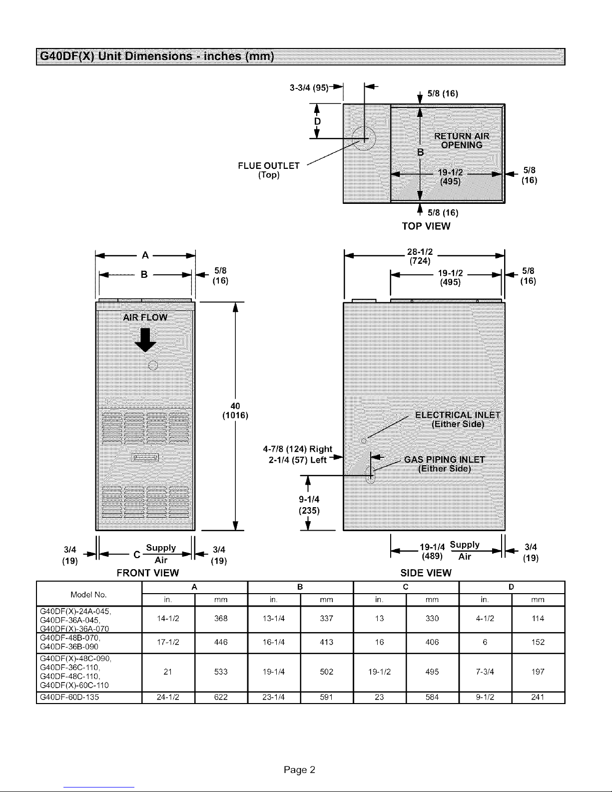
5/8 (16)
D
FLUE OUTLET 5/8
(Top) (16)
5/8 (16)
TOP VIEW
,_ A -_
9v-------- B _
ql- 5/8
(16)
!i!i!ii!i!i!i!ii!i!i!i!ii!i!i!i!ii!i!i!i!ii!i!i!i!ii!i!i!i¸I I!I!I!I!II!I!I!I!III!I!
40
(1016)
4-7/8 (124) Right
2-1/4 (57) Left -I_
9-1/4
(235)
28-1/2
(724)
-- 9-1/2 --
(495)
5/8
(16)
,,,Jl-- suoo,
(19) C Air _ (19)
FRONT VIEW
Model No.
G40DF(X)-24A-045,
G40DF-36A-045, 14-1/2 368 13-1/4 337 13 4-1/2 114
G40DFIX)-36A-070
G40DF-48B-070, 17-1/2 446 16-1/4 413 16 6 152
G40DF-36B-090
G40DF(X)-48C-090,
G40DF-36C-110, 21 533 19-1/4 502 19-1/2 7-3/4 197
G40DF-48C-110,
G40DF(X)-60C-110
G40DF-60D-135 24-1/2 622 23-1/4 591 23 9-1/2 241
A B D
in. mm in. mm in. mm
Page 2
_ 9-1/4 Supply
(489) Air
SIDE VIEW
c
in mm
33o
4o6
495
584
J
v I
3/4
(19)
Page 3
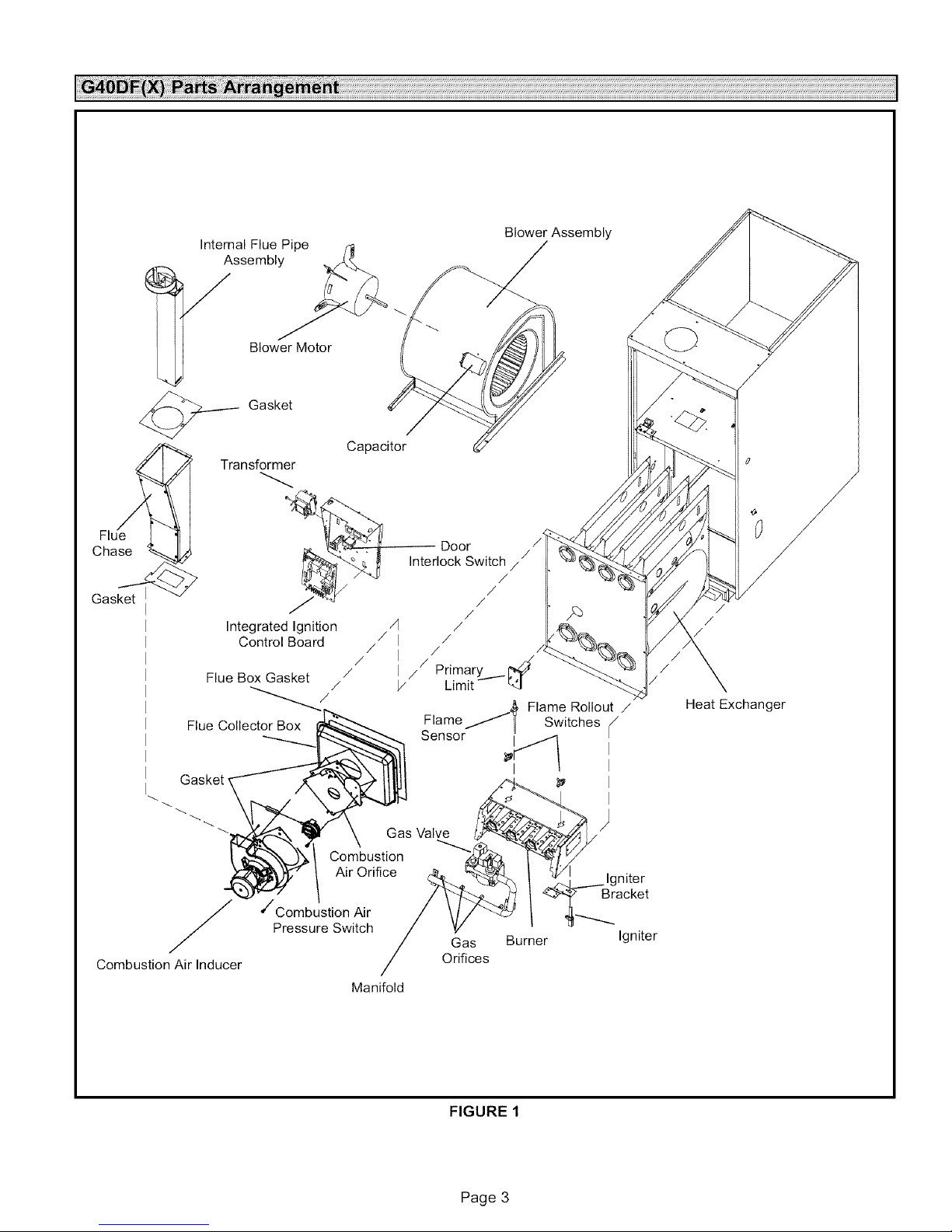
Internal Flue Pipe
Assembly
Y Blower Motor
Gasket
Transformer
Integrated Ignition /]
Control Board /
Flue Box Gasket /
Flue Collector Box
/
/
Capacitor
/I
/
Blower Assembly
Door /
Interlock Switch / /
/
I /
I // Primarg ._ _/
/ Limit %1
Flame Switches i/
/
/
/
/
/
/_, Flame Rollout /
/
/
Heat Exchanger
Gasket,
'/'Combustion Air
Y
Combustion Air Inducer
Pressure Switch
Air Orifice
Manifold
Sensor _'[_ II
/
Gas
Orifices
FIGURE 1
Burner Igniter
Page 3
I
I
lgniter
racket
Page 4
TheG40DF(X)gasfurnaceisshippedreadyforinstalla-
tioninthedownflowpositionfueledbynaturalgas,Acon-
versionkit(orderedseparately)isrequiredforuseinpro-
pane/LPgasapplications.
Package 1 of 1 contains
1 - Assembled G40DF(X) unit
1 - Bag assembly containing the following:
3 -Wire nuts
1 - Snap bushing
1 - Snap plug
1 - Wire tie
1 -Vent warning label
1 -Owner's manual and warranty card
The following items may be ordered separately:
1- Thermostat
1 - Propane/LP changeover kit
Check equipment for shipping damage. If you find any
damage, immediately contact the last carrier.
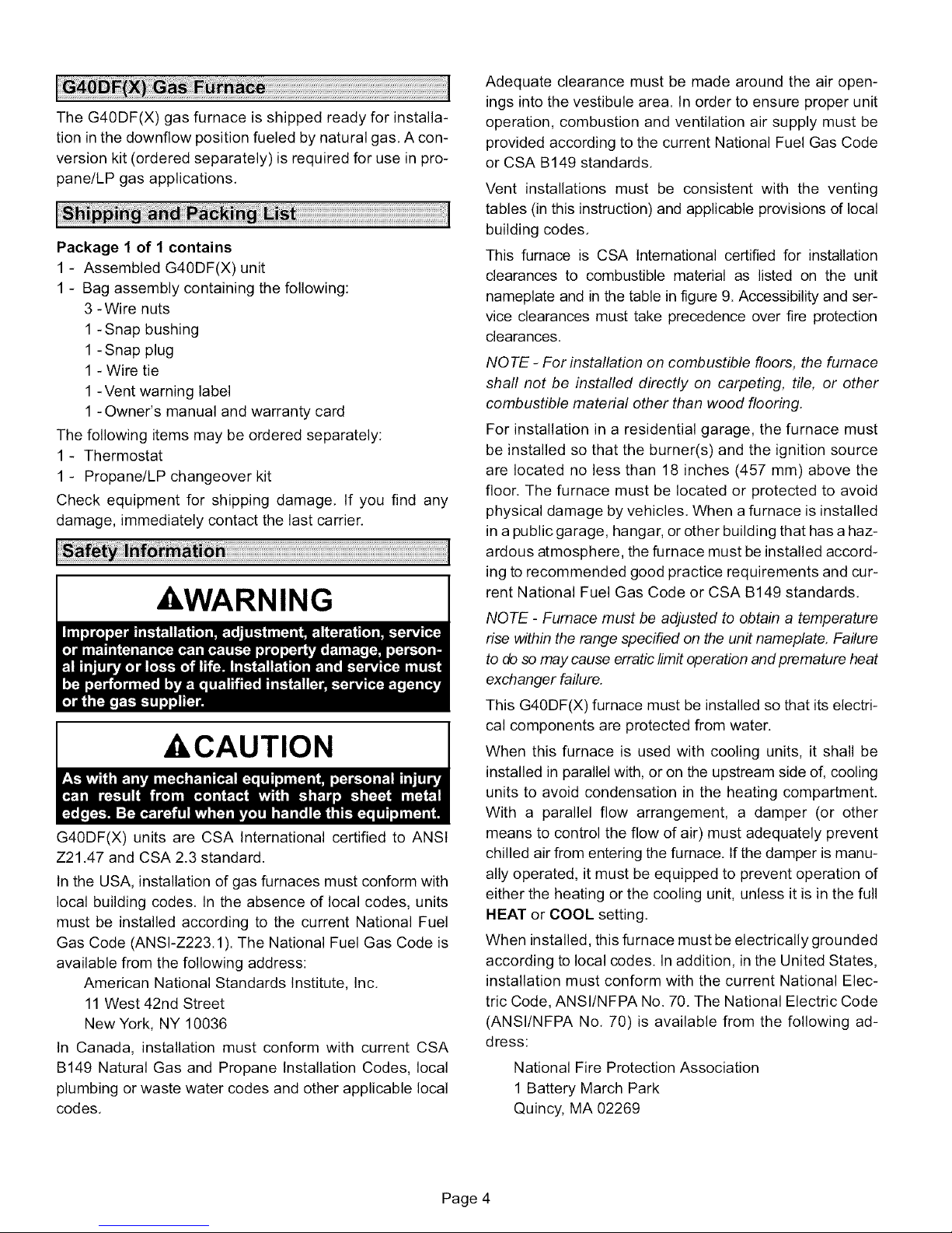
,WARNING
,&,CAUTION
G40DF(X) units are CSA International certified to ANSI
Z21.47 and CSA 2.3 standard.
In the USA, installation of gas furnaces must conform with
local building codes. In the absence of local codes, units
must be installed according to the current National Fuel
Gas Code (ANSI-Z223.1). The National Fuel Gas Code is
available from the following address:
American National Standards Institute, Inc.
11 West 42nd Street
New York, NY 10036
In Canada, installation must conform with current CSA
B149 Natural Gas and Propane Installation Codes, local
plumbing or waste water codes and other applicable local
codes.
Adequate clearance must be made around the air open-
ings into the vestibule area. In order to ensure proper unit
operation, combustion and ventilation air supply must be
provided according to the current National Fuel Gas Code
or CSA B149 standards.
Vent installations must be consistent with the venting
tables (in this instruction) and applicable provisions of local
building codes.
This furnace is CSA Intemational certified for installation
clearances to combustible material as listed on the unit
nameplate and in the table infigure 9. Accessibility and ser-
vice clearances must take precedence over fire protection
clearances.
NOTE - For installation on combustible floors, the furnace
shall not be installed directly on carpeting, tile, or other
combustible material other than wood flooring.
For installation in a residential garage, the furnace must
be installed so that the burner(s) and the ignition source
are located no less than 18 inches (457 mm) above the
floor. The furnace must be located or protected to avoid
physical damage by vehicles. When a furnace is installed
in a public garage, hangar, or other building that has a haz-
ardous atmosphere, the furnace must be installed accord-
ing to recommended good practice requirements and cur-
rent National Fuel Gas Code or CSA B149 standards.
NOTE - Furnace must be adjusted to obtain a temperature
rise within the range specified on the unit nameplate. Failure
to do so may cause erratic limit operation and premature heat
exchanger failure.
This G40DF(X) furnace must be installed so that its electri-
cal components are protected from water.
When this furnace is used with cooling units, it shall be
installed in parallel with, or on the upstream side of, cooling
units to avoid condensation in the heating compartment.
With a parallel flow arrangement, a damper (or other
means to control the flow of air) must adequately prevent
chilled air from entering the furnace. If the damper is manu-
ally operated, it must be equipped to prevent operation of
either the heating or the cooling unit, unless it is in the full
HEAT or COOL setting.
When installed, this furnace must be electrically grounded
according to local codes. Inaddition, in the United States,
installation must conform with the current National Elec-
tric Code, ANSI/NFPA No. 70. The National Electric Code
(ANSI/NFPA No. 70) is available from the following ad-
dress:
National Fire Protection Association
1 Battery March Park
Quincy, MA 02269
Page 4
Page 5
InCanada,allelectricalwiringandgroundingfortheunit
mustbeinstalledaccordingtothecurrentregulationsofthe
CanadianElectricalCodePartI(CSAStandardC22.1)
and/orlocalcodes.
NOTE - This furnace is designed for a minimum continu-
ous return air temperature of 60°F (16°C) or intermittent
operation down to 55°F (13°C) dry bulb in cases where a
night setback thermostat is used. Return air temperature
must not exceed 85°F (29 °C) dry bulb.
NOTE - G4ODF(X) series units should not be installed as a
unit heater.
The G40DF(X) furnace may be installed in alcoves, clos-
ets, attics, basements, garages, and utility rooms in the
downflow position.
This furnace design has not been CSA International certi-
fied for installation in mobile homes, recreational vehicles,
or outdoors.
Lennox does not recommend the use of G40DF(X) units as
a construction heater during any phase of construction.
Very low return air temperatures, harmful vapors and op-
eration of the unit with clogged or misplaced filters will dam-
age the unit.
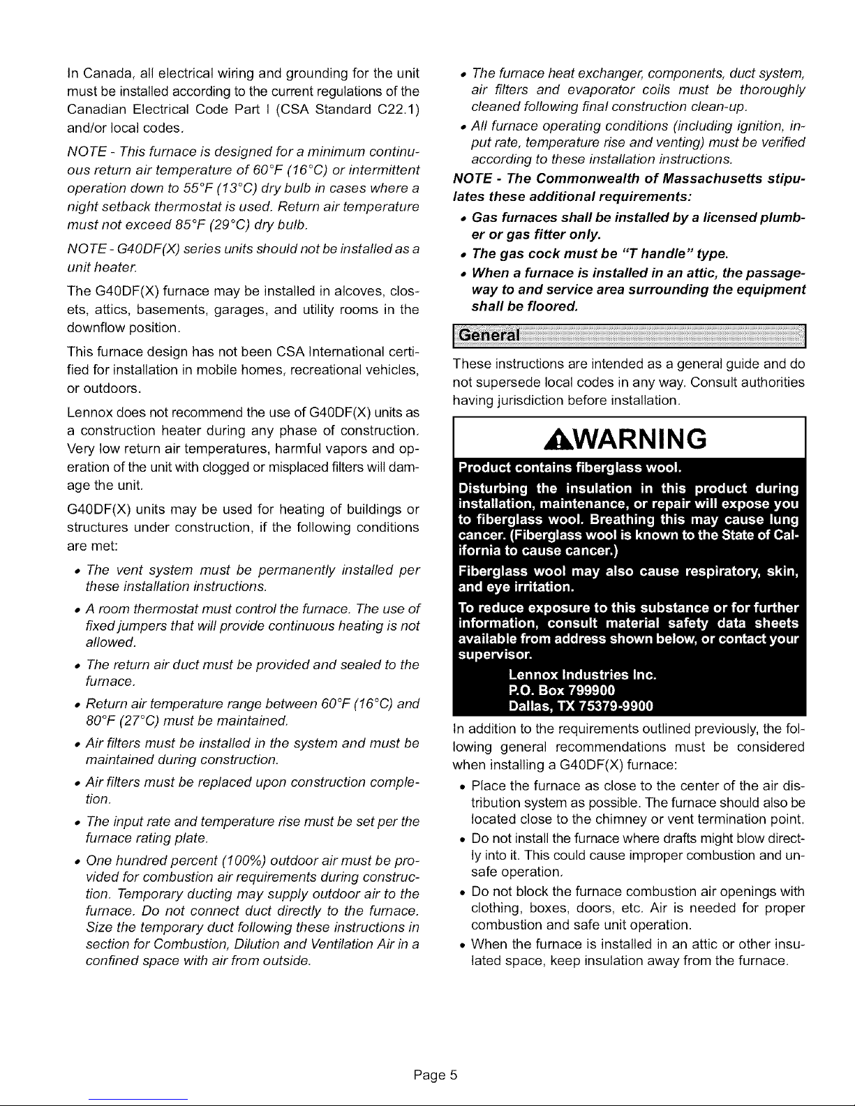
• The furnace heat exchanger, components, duct system,
air filters and evaporator coils must be thoroughly
cleaned following final construction clean-up.
• All furnace operating conditions (including ignition, in-
put rate, temperature rise and venting) must be verified
according to these installation instructions.
NOTE - The Commonwealth of Massachusetts stipu-
lates these additional requirements:
• Gas furnaces shall be installed by a ticensedplumb-
er or gas fitter only.
• The gas cock must be "T handle" type.
• When a furnace is installed in an attic, the passage-
way to and service area surrounding the equipment
shall be floored.
These instructions are intended as a general guide and do
not supersede local codes in any way. Consult authorities
having jurisdiction before installation.
, WARNING
G40DF(X) units may be used for heating of buildings or
structures under construction if the following conditions
are met:
• The vent system must be 3ermanently installed per
these installation instructions.
• A room thermostat must control the furnace. The use of
fixed jumpers that will provide continuous heating is not
allowed.
• The return air duct must be provided and sealed to the
furnace.
• Return air temperature range between 60°F (16°C) and
80°F (27°C) must be maintained.
• Air filters must be installed in the system and must be
maintained during construction.
• Air filters must be replaced upon construction comple-
tion.
• The input rate and temperature rise must be set per the
furnace rating plate.
• One hundred percent (100%) outdoor air must be pro-
vided for combustion air requirements during construc-
tion. Temporary ducting may supply outdoor air to the
furnace. Do not connect duct directly to the furnace.
Size the temporary duct following these instructions in
section for Combustion, Dilution and Ventilation Air in a
confined space with air from outside.
In addition to the requirements outlined previously, the fol-
lowing general recommendations must be considered
when installing a G40DF(X) furnace:
• Place the furnace as close to the center of the air dis-
tribution system as possible. The furnace should also be
located close to the chimney or vent termination point.
• Do not install the furnace where drafts might blow direct-
ly into it. This could cause improper combustion and un-
safe operation.
• Do not block the furnace combustion air openings with
clothing, boxes, doors, etc. Air is needed for proper
combustion and safe unit operation.
• When the furnace is installed in an attic or other insu-
lated space, keep insulation away from the furnace.
Page 5
Page 6
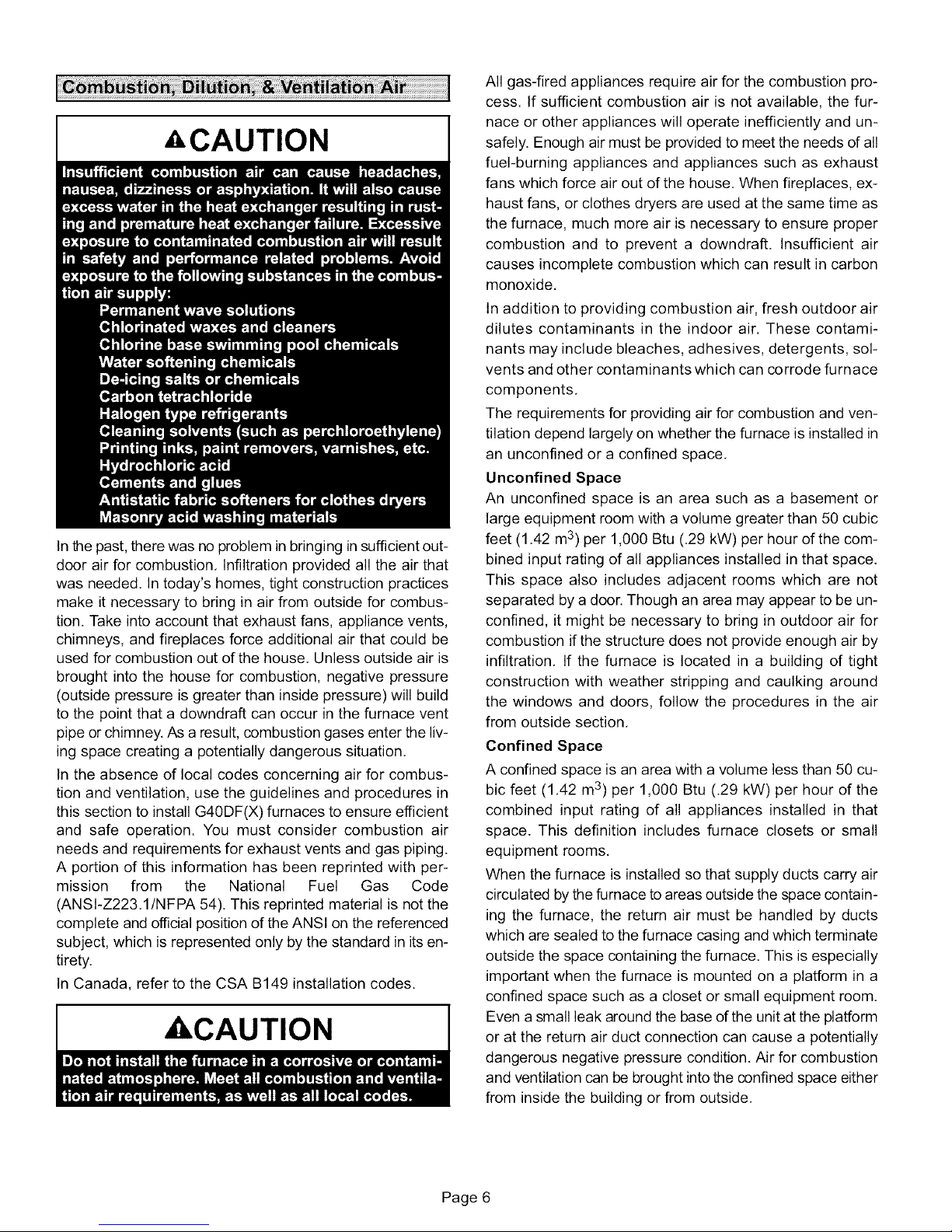
ACAUTION
In the past, there was no problem in bringing in sufficient out-
door air for combustion, Infiltration provided all the air that
was needed, In today's homes, tight construction practices
make it necessary to bring in air from outside for combus-
tion. Take into account that exhaust fans, appliance vents,
chimneys, and fireplaces force additional air that could be
used for combustion out of the house. Unless outside air is
brought into the house for combustion, negative pressure
(outside pressure is greater than inside pressure) will build
to the point that a downdraft can occur in the furnace vent
pipe or chimney. As a result, combustion gases enter the liv-
ing space creating a potentially dangerous situation.
In the absence of local codes concerning air for combus-
tion and ventilation, use the guidelines and procedures in
this section to install G40DF(X) furnaces to ensure efficient
and safe operation. You must consider combustion air
needs and requirements for exhaust vents and gas piping.
A portion of this information has been reprinted with per-
mission from the National Fuel Gas Code
(ANSl-Z223.1/NFPA 54). This reprinted material is not the
complete and official position of the ANSl on the referenced
subject, which is represented only by the standard in its en-
tirety.
In Canada, refer to the CSA B149 installation codes.
ACAUTION
All gas-fired appliances require air for the combustion pro-
cess. If sufficient combustion air is not available, the fur-
nace or other appliances will operate inefficiently and un-
safely. Enough air must be provided to meet the needs of all
fuel-burning appliances and appliances such as exhaust
fans which force air out of the house. When fireplaces, ex-
haust fans, or clothes dryers are used at the same time as
the furnace, much more air is necessary to ensure proper
combustion and to prevent a downdraft. Insufficient air
causes incomplete combustion which can result in carbon
monoxide.
In addition to providing combustion air, fresh outdoor air
dilutes contaminants in the indoor air. These contami-
nants may include bleaches, adhesives, detergents, sol-
vents and other contaminants which can corrode furnace
components.
The requirements for providing air for combustion and ven-
tilation depend largely on whether the furnace is installed in
an unconfined or a confined space.
Unconfined Space
An unconfined space is an area such as a basement or
large equipment room with a volume greater than 50 cubic
feet (1.42 m3) per 1,000 Btu (.29 kW) per hour of the com-
bined input rating of all appliances installed in that space.
This space also includes adjacent rooms which are not
separated by a door. Though an area may appear to be un-
confined, it might be necessary to bring in outdoor air for
combustion if the structure does not provide enough air by
infiltration. If the furnace is located in a building of tight
construction with weather stripping and caulking around
the windows and doors, follow the procedures in the air
from outside section.
Confined Space
A confined space is an area with a volume less than 50 cu-
bic feet (1.42 m3) per 1,000 Btu (.29 kW) per hour of the
combined input rating of all appliances installed in that
space. This definition includes furnace closets or small
equipment rooms.
When the furnace is installed so that supply ducts carry air
circulated by the furnace to areas outside the space contain-
ing the furnace, the return air must be handled by ducts
which are sealed to the furnace casing and which terminate
outside the space containing the furnace. This is especially
important when the furnace is mounted on a platform in a
confined space such as a closet or small equipment room.
Even a small leak around the base of the unit at the platform
or at the return air duct connection can cause a potentially
dangerous negative pressure condition. Air for combustion
and ventilation can be brought into the confined space either
from inside the building or from outside.
Page 6
Page 7
EQUIPMENT IN CONFINED
CHIMNEY
VENT
FURNACE
_ WiTER
I I I I I II I I I I I I II I I I
I I
SPACE ALL AIR FROM INSIDE
HEATER
OPENINGS
(To Adjacent
Room)
I I I I
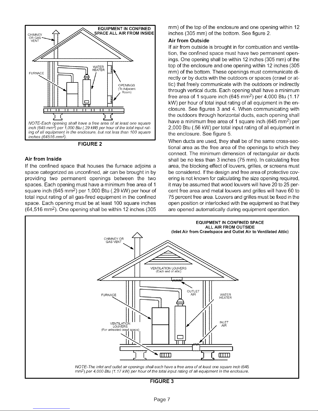
NOTE-Each opening shall have a free area of at least one square
inch (645 mm'2_')per 1,000 Btu (.29 kW) per hour of the total input rat-
ing of all equipment in the enclosure, but not less than 100 square
inches (64516 mm2).
FIGURE 2
Air from Inside
If the confined space that houses the furnace adjoins a
space categorized as unconfined, air can be brought in by
providing two permanent openings between the two
spaces. Each opening must have a minimum free area of 1
square inch (645 mm2) per 1,000 Btu (.29 kW) per hour of
total input rating of all gas-fired equipment in the confined
space, Each opening must be at least 100 square inches
(64,516 mm2), One opening shall be within 12 inches (305
mm) of the top of the enclosure and one opening within 12
inches (305 mm) of the bottom. See figure 2.
Air from Outside
If air from outside is brought in for combustion and ventila-
tion, the confined space must have two permanent open-
ings, One opening shall be within 12 inches (305 mm) of the
top of the enclosure and one opening within 12 inches (305
mm) of the bottom, These openings must communicate di-
rectly or by ducts with the outdoors or spaces (crawl or at-
tic) that freely communicate with the outdoors or indirectly
through vertical ducts. Each opening shall have a minimum
free area of 1 square inch (645 mm2) per 4,000 Btu (1,17
kW) per hour of total input rating of all equipment in the en-
closure, See figures 3 and 4. When communicating with
the outdoors through horizontal ducts, each opening shall
have a minimum free area of 1 square inch (645 mm 2) per
2,000 Btu (.56 kW) per total input rating of all equipment in
the enclosure. See figure 5.
When ducts are used, they shall be of the same cross-sec-
tional area as the free area of the openings to which they
connect. The minimum dimension of rectangular air ducts
shall be no less than 3 inches (75 mm). In calculating free
area, the blocking effect of louvers, grilles, or screens must
be considered. Ifthe design and free area d protective cov-
ering is not known for calculating the size opening required,
it may be assumed that wood louvers will have 20 to 25 per-
cent free area and metal louvers and grilles will have 60 to
75 percent free area. Louvers and grilles must be fixed in the
open position or interlocked with the equipment so that they
are opened automatically during equipment operation.
EQUIPMENT IN CONFINED SPACE
ALL AIR FROM OUTSIDE
(Inlet Air from Crawlspace and Outlet Air to Ventilated Attic)
CHIMNEY OR
GAS VENT
VENTILATION LOUVERS
(Each end of attic)
l ...... I
FURNACE AIR WATER
VENTILATION INLET
LOUVERS AIR
(For unheated crawl !
OUTLET
HEATER
q
rrmq
NOTE- The inlet and outlet air openings shall each have a free area of at least one square inch (645
mm2) per 4,000 Btu (1.17 kW) per hour of the total input rating of all equipment in the enclosure.
FIGURE 3
Page 7
Page 8
EQUIPMENT IN CONFINED SPACE
ALL AIR FROM OUTSIDE
CHIMNEY
OR GAS
VENT_
FURNACE
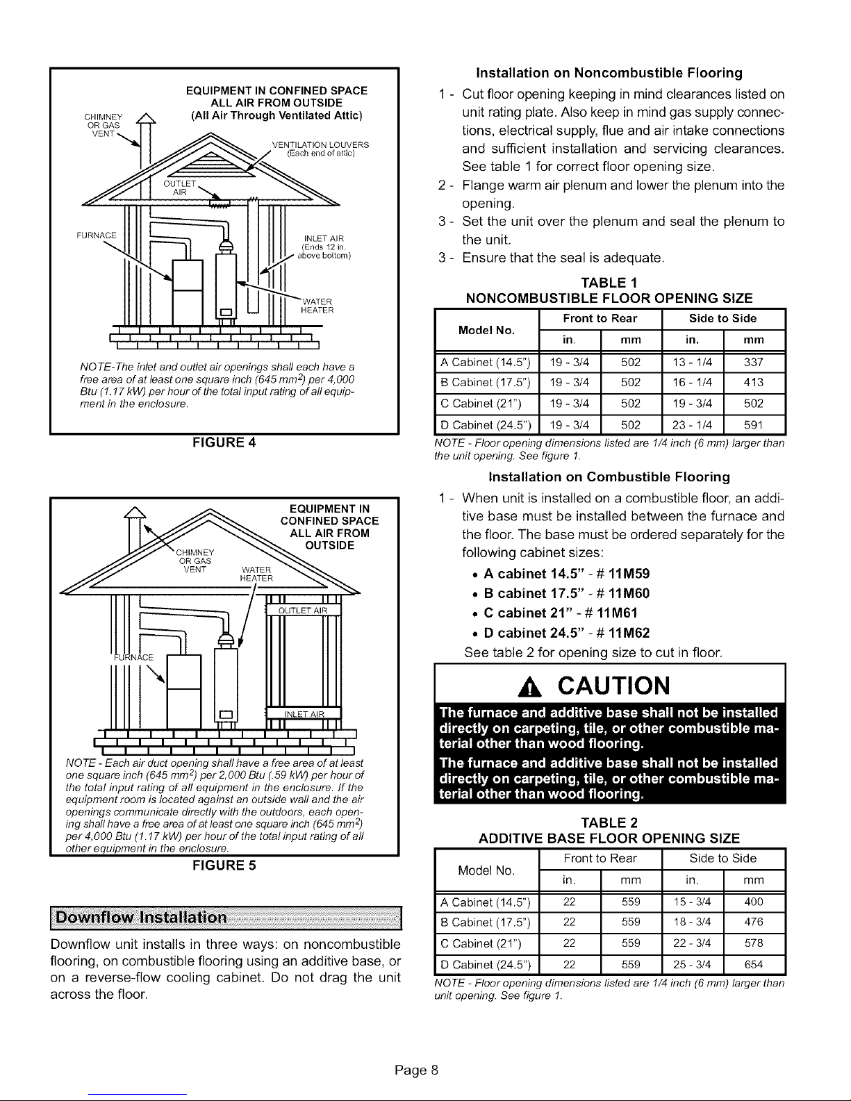
NO TE- The inlet and outlet air openings shall each have a
free area of at least one square inch (645 mm 2)per 4,000
Btu (1.17 kW) per hour of the total input rating of all equip-
ment in the enclosure.
(All Air Through Ventilated Attic)
VENTILATION LOUVERS
(Each end of attic)
INLET AIR
(Ends 12 in.
above bottom)
HEATER
FIGURE 4
A _ EQUIPMENT IN
TT_. JJ_ CONFINED SPACE
I I "_/--/'Y _ ALLAIRFROM
OUTLET AIR
FURNACE
Installation on Noncombustible Flooring
1 - Cut floor opening keeping in mind clearances listed on
unit rating plate. Also keep in mind gas supply connec-
tions, electrical supply, flue and air intake connections
and sufficient installation and servicing clearances,
See table 1 for correct floor opening size.
2 - Flange warm air plenum and lower the plenum into the
opening.
3 - Set the unit over the plenum and seal the plenum to
the unit,
3 - Ensure that the seal is adequate,
TABLE 1
NONCOMBUSTIBLE FLOOR OPENING SIZE
Model No.
A Cabinet (14.5")
B Cabinet (17.5")
C Cabinet (21")
D Cabinet (24.5")
NOTE - Floor opening dimensions listed are 1/4 inch (6 mm) larger than
the unit opening. See figure 1.
Front to Rear
in. mm
19 - 3/4 502
19 - 3/4 502
19 - 3/4 502
19 - 3/4 502
Side to Side
in.
13 - 1/4
16 - 1/4
19 - 3/4
23- 1/4
mm
337
413
5O2
591
Installation on Combustible Flooring
1 - When unit is installed on a combustible floor, an addi-
tive base must be installed between the furnace and
the floor. The base must be ordered separately for the
following cabinet sizes:
• A cabinet 14.5" -# 11M59
• B cabinet 17.5" -# 11M60
• C cabinet 21" -# 11M61
• D cabinet 24.5" - # 11M62
See table 2 for opening size to cut in floor.
I1"-
I ii I I I I I I I I I I I T_"I
NO TE - Each air duct opening shall have a free area of at least
one square inch (645 mm 2)per 2,000 Btu (.59 kW) per hour of
the total input rating of all equipment in the enclosure. If the
equipment room is located against an outside wall and the air
openings communicate directly with the outdoors, each open-
ing shaft have a free area of at least one square inch (645 mm2)
per 4,000 Btu (1.17 kW) per hour of the total input rating of all
other equipment in the enclosure.
FIGURE 5
Downflow unit installs in three ways: on noncombustible
flooring, on combustible flooring using an additive base, or
on a reverse-flow cooling cabinet, Do not drag the unit
across the floor.
,A, CAUTION
I
TABLE 2
ADDITIVE BASE FLOOR OPENING SIZE
Model No.
A Cabinet (14.5")
B Cabinet (17.5")
C Cabinet (21")
D Cabinet (24.5")
NOTE - Floor opening dimensions listed are 1/4 inch (6 mm) larger than
unit opening. See figure 1.
Frontto Rear
in. mm
22 559
22 559
22 559
22 559
Page 8
Side to Side
in.
15 - 3/4
18 - 3/4
22 - 3/4
25 - 3/4
am
400
476
578
654
Page 9
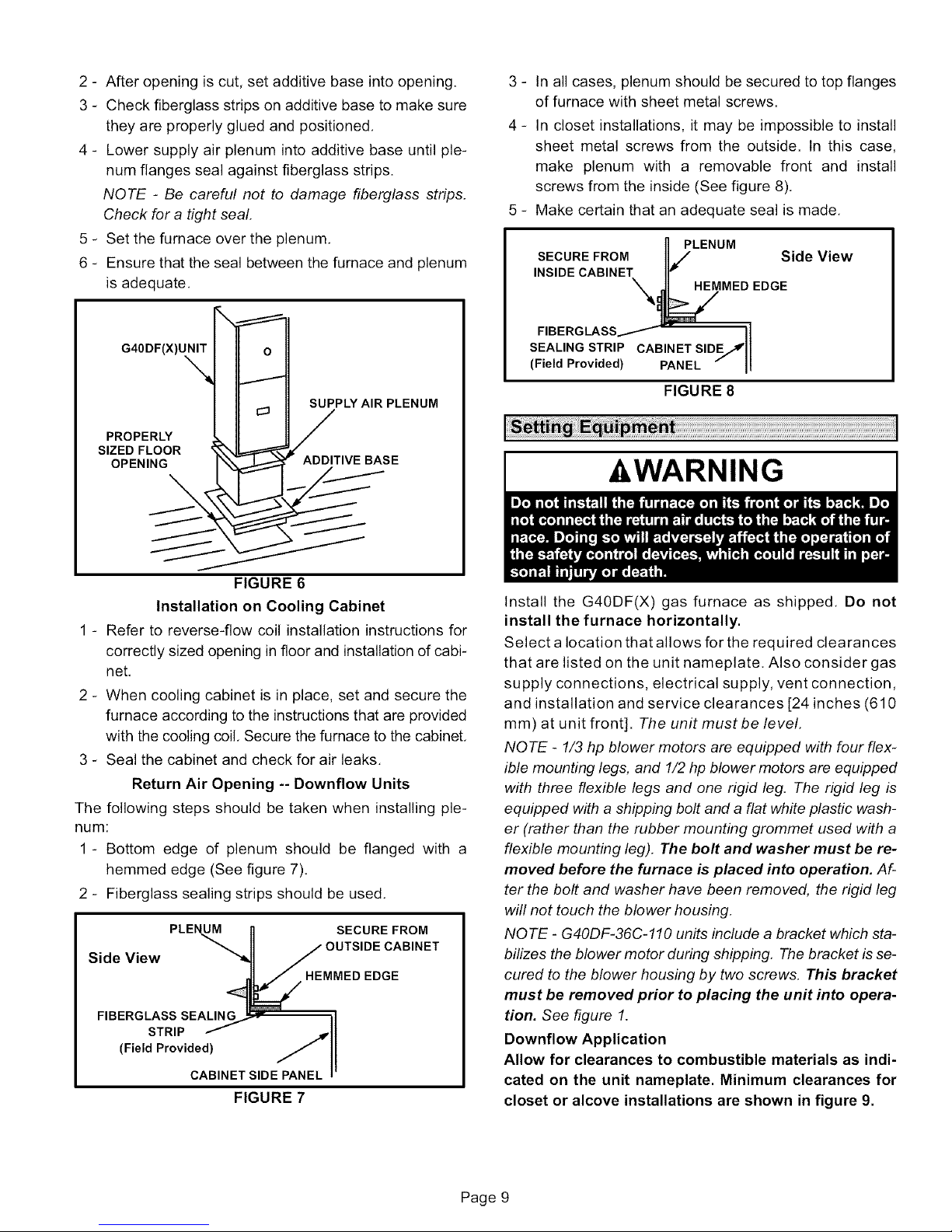
2- Afteropeningiscut,setadditivebaseintoopening.
3- Checkfiberglassstripsonadditivebasetomakesure
theyareproperlygluedandpositioned.
4- Lowersupplyairplenumintoadditivebaseuntilple-
numflangessealagainstfiberglassstrips.
NOTE - Be careful not to damage fiberglass strips.
Check for a tight seal.
5 - Set the furnace over the plenum.
6 - Ensure that the seal between the furnace and plenum
is adequate.
G40DF(X)UNIT
%
PROPERLY
SIZED FLOOR _X'xI_"
OPENING I\\_ _ ADDITIVE BASE
SUPPLY AIR PLENUM
3 - In all cases, plenum should be secured to top flanges
of furnace with sheet metal screws.
4 - In closet installations, it may be impossible to install
sheet metal screws from the outside. In this case,
make plenum with a removable front and install
screws from the inside (See figure 8).
5 - Make certain that an adequate seal is made.
n PLENUM
SECURE FROM IIJ Side View
INSIDE CABINEX_ME o EDGE
FIBERGLASS/ -
SEALING STRIP CABINET SIDE_ I
(Field Provided) PANEL --II
FIGURE 8
I
AWARNING
FIGURE 6
Installation on Cooling Cabinet
1 - Refer to reverse-flow coil installation instructions for
correctly sized opening in floor and installation of cabi-
net.
2 - When cooling cabinet is in place, set and secure the
furnace according to the instructions that are provided
with the cooling coil. Secure the furnace to the cabinet.
3 - Seal the cabinet and check for air leaks.
Return Air Opening -- Downflow Units
The following steps should be taken when installing ple-
num:
1 - Bottom edge of plenum should be flanged with a
hemmed edge (See figure 7).
2 - Fiberglass sealing strips should be used.
PLENUM SECURE FROM
CABINET
Side View
HEMMEDEDGE
FIBERGLASS SEALING
STRIP
(Field Provided)
CABINET SIDE PANEL
FIGURE 7
Install the G40DF(X) gas furnace as shipped. Do not
install the furnace horizontally.
Select a location that allows for the required clearances
that are listed on the unit nameplate. Also consider gas
supply connections, electrical supply, vent connection,
and installation and service clearances [24 inches (610
mm) at unit front]. The unit must be level.
NOTE - 1/3 hp blower motors are equipped with four flex-
ible mounting legs, and 1/2 hp blower motors are equipped
with three flexible legs and one rigid leg. The rigid leg is
equipped with a shipping bolt and a flat white plastic wash-
er (rather than the rubber mounting grommet used with a
flexible mounting leg). The bolt and washer must be re-
moved before the furnace is placed into operation. Af-
ter the bolt and washer have been removed, the rigid leg
will not touch the blower housing.
NOTE - G40DF-36C-110 units include a bracket which sta-
bilizes the blower motor during shipping. The bracket is se-
cured to the blower housing by two screws. This bracket
must be removed prior to placing the unit into opera-
tion. See figure 1.
Downflow Application
Allow for clearances to combustible materials as indi-
cated on the unit nameplate. Minimum clearances for
closet or alcove installations are shown in figure 9.
Page 9
Page 10
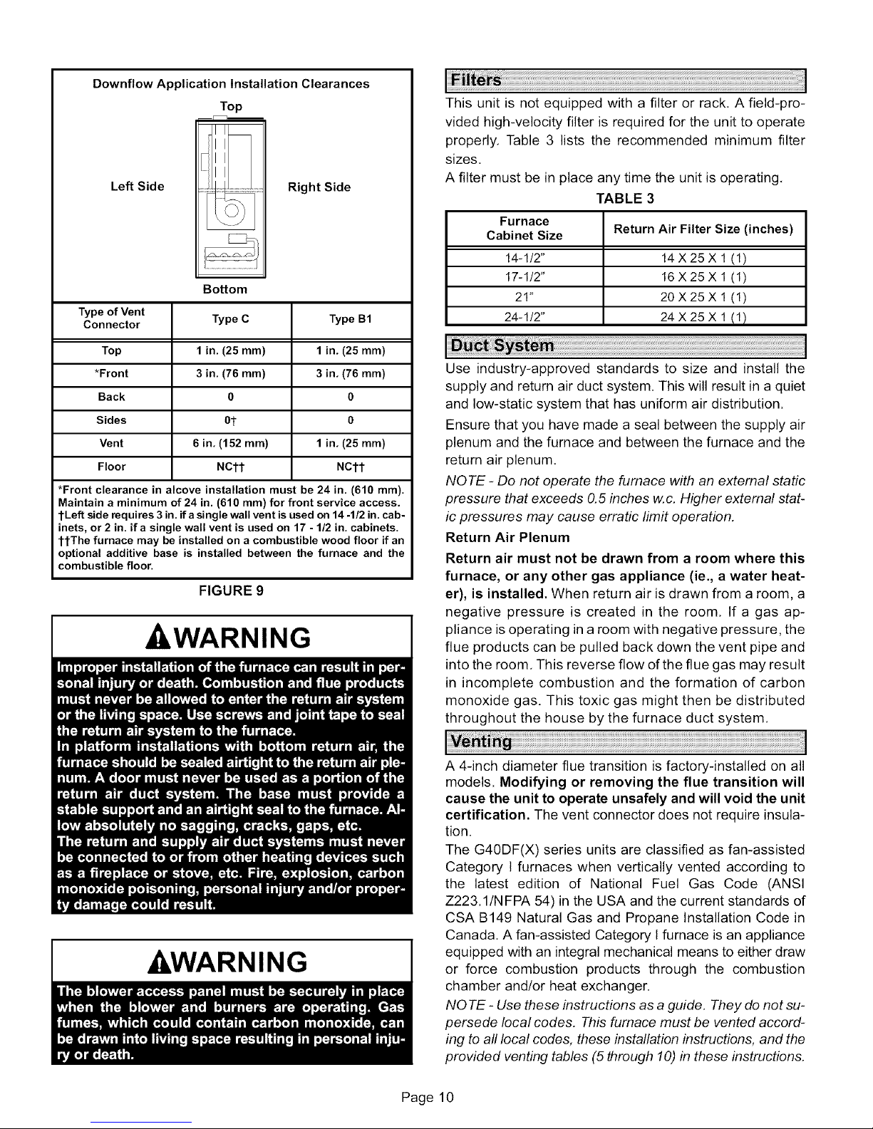
DownflowApplication Installation Clearances
Top
Left Side
¢:::_T:T:T;
Right Side
Bottom
Type of Vent Type B1
Connector
Type C
This unit is not equipped with a filter or rack. A field-pro-
vided high-velocity filter is required for the unit to operate
properly, Table 3 lists the recommended minimum filter
sizes,
A filter must be in place any time the unit is operating,
TABLE 3
Furnace
Cabinet Size Return Air Filter Size (inches)
14-1/2" 14 X 25 X 1 (1)
17-1/2" 16 X25 X 1(1)
21" 20X25X 1(1)
24-1/2" 24 X25 X 1 (1)
Top 1 in. (25 ram)
*Front 3 in. (76 ram)
Back 0
Sides 0
Vent 1 in. (25 ram)
Floor NCtt
*Front clearance in alcove installation must be 24 in. (610 ram).
Maintain a minimum of 24 in. (610 ram) for front service access.
tLeft side requires 3 in. if a single wall vent is used on 14 -1/2 in. cab-
inets, or 2 in. if a single wall vent is used on 17 - 1/2 in. cabinets.
tiThe furnace may be installed on a combustible wood floor if an
optional additive base is installed between the furnace and the
combustible floor.
1 in. (25 ram)
3 in. (76 ram)
0
ot
6 in. (152 ram)
NCtt
FIGURE 9
-&WARNING
......
Use industry-approved standards to size and install the
supply and return air duct system. This will result in a quiet
and low-static system that has uniform air distribution.
Ensure that you have made a seal between the supply air
plenum and the furnace and between the furnace and the
return air plenum.
NOTE - Do not operate the furnace with an external static
pressure that exceeds 0.5 inches w.c. Higher external stat-
ic pressures may cause erratic limit operation.
Return Air Plenum
Return air must not be drawn from a room where this
furnace, or any other gas appliance (ie., a water heat-
er), is installed. When return air is drawn from a room, a
negative pressure is created in the room, If a gas ap-
pliance is operating in a room with negative pressure, the
flue products can be pulled back down the vent pipe and
into the room, This reverse flow of the flue gas may result
in incomplete combustion and the formation of carbon
monoxide gas. This toxic gas might then be distributed
throughout the house by the furnace duct system,
-&WARNING
A 4-inch diameter flue transition is factory-installed on all
models. Modifying or removing the flue transition will
cause the unit to operate unsafely and will void the unit
certification. The vent connector does not require insula-
tion.
The G40DF(X) series units are classified as fan-assisted
Category I furnaces when vertically vented according to
the latest edition of National Fuel Gas Code (ANSI
Z223.1/NFPA 54) in the USA and the current standards of
CSA B149 Natural Gas and Propane Installation Code in
Canada. A fan-assisted Category I furnace is an appliance
equipped with an integral mechanical means to either draw
or force combustion products through the combustion
chamber and/or heat exchanger.
NOTE - Use these instructions as a guide. They do not su-
persede local codes. This furnace must be vented accord-
ing to all local codes, these installation instructions, and the
provided venting tables (5 through 10) in these instructions.
Page 10
Page 11

Theventingtablesinthismanualwereextractedfromthe
NationalFuelGasCode(ANSIZ223.1/NFPA54)andare
providedasaguideforproperventinstallation.Properap-
plication,termination,constructionandlocationof vents
mustconformtolocalcodeshavingjurisdiction.Intheab-
senced local codes, the NFGC serves as the defining doc-
ument,
Refer to the tables and the venting information contained in
these instructions to properly size and install the venting
system.
klMPORTANT
&WARNING
VENT CONNECTION
VENT
PIPE
FLUE TRANSITION
COLLAR
FURNACE
FIGURE 10
Masonry chimneys used to vent Category I central fur-
naces must be either tile-lined or lined with a listed metal
lining system or dedicated gas vent, Unlined masonry
chimneys are prohibited, See figures 11 and 12 for com-
mon venting.
A chimney with one or more sides exposed to the outside of
the structure is considered to be an exterior chimney.
An exterior masonry chimney that is not tile-lined must be
lined with B1 vent or a listed insulated flexible metal vent.
An exterior tile-lined chimney that is sealed and capped
may be lined with a listed uninsulated flexible metal vent,
If the existing chimney will not accommodate a B1 vent or
an insulated flexible vent pipe liner, either the chimney
must be rebuilt to accommodate one of these liners or an
alternate approved venting method must be found.
Insulation for the flexible vent pipe must be an encapsu-
lated fiberglass sleeve recommended by the flexible vent
pipe manufacturer. See figure 11.
DO NOT insulate the space between the liner and the
chimney wall with puffed mica or any other loose gran-
ular insulating material
A fan-assisted furnace may be commonly vented into an
existing lined masonry chimney if the following conditions
are met:
• The chimney is currently serving at least one drafthood
equipped appliance
• The vent connectors and chimney are sized according
to the provided venting tables for the USA, and the ap-
propriate venting tables in the standards of CSA B149
Natural Gas and Propane Installation Code in Canada
Common Venting Using Metal-Lined Masonry Chimney
SEALED
J
T MAX. LENGTH
2VE%O%%OTOR "
* SEE NOTE 1
BELOW.
II
II EXTERIOR
CHIMNEY WITH
II METALUNEB
II
'1
__ .J
Use self-drilling sheet metal screws or a mechanical fas-
tener to firmly secure the vent pipe to the round collar of the
flue transition. If self-drilling screws are used to attach the
vent pipe, it is recommended that three be used. Drive one
self-drilling screw through the front and one through each
side of the vent pipe and collar, See figure 10.
Install the first vent connector elbow at a minimum of six
inches (152 mm) from the furnace vent outlet,
Venting Using a Masonry Chimney
The following additional requirements apply when a lined
masonry chimney is used to vent this furnace.
Page 11
PERMANENTLY
SEALED FIREPLACE
OPENING
NOTE 1 - Refer to the provided venting tables for iostallations in the USA
and the venting tables in CSA-B149 for installations Canada.
NOTE 2 - Either single-walled or double-walled vent connector may be
used. Refer to the capacity requirements shown in the provided venting
tables for installations in USA and the venting tables in current CSA-
B149 for installations in Canada.
FIGURE 11
Page 12

Common Venting Using Tile-Lined Interior Masonry Chimne
' and Combined Vent Connector
J
NOTE- Refer to provided venting tables
for installations in the USA and the
MINIMUM LENGTH = AS SHORT AS PRACTICAL.
FOR MAXIMUM LENGTH SEE NOTE TO LEFT
J
m
INTERIOR TILE=LINED
MASONRY CHIMNEY
NOTE - the chimney must be properly
sized per provided venting tables or
lined with listed metal lining system.
ive%%an,se.nl a n.ar ea.tcsA-B,,,for
FU
OTHER
APPLIANCE
PERMANENTLY
SEALED FIREPLACE
OPENING
"_Row
NOTE - Either single-walled or double-walled vent connector may be used. Refer to the capacity requirements as shown in the pro-
vided venting tables for installations in USA and the venting tables in current CSA-B149 for installations in Canada.
FIGURE 12
General Venting Requirements
AIMPORTANT Vent all G40DF(X)furnaces according to these instruc-
tions:
1 - Vent diameter recommendations and maximum allow-
able piping runs are found in the provided venting tables
for the USA, and the appropriate venting tables in the
standards of CSA B149 Natural Gas and Propane
Installation Codes for Canada.
2 - In no case should the vent or vent connector diameter
If type B1 double-wall vent is used inside a chimney, no oth-
er appliance can be vented into the chimney. The outer wall
of type B1 vent pipe must not be exposed to flue products.
A type B1 vent or masonry chimney liner shall terminate
above the roof surface with a listed cap or a listed roof as-
sembly according to the terms of their respective listings
and the vent manufacturer's instructions.
When inspection reveals that an existing chimney is not
safe for the intended purpose, it shall be rebuilt to conform
to nationally recognized standards, lined or relined with
suitable materials, or replaced with a gas vent or chimney
suitable for venting G40DF(X) series units. The chimney
passageway must be checked periodically to ensure that it
is clear and free of obstructions.
Do not install a manual damper, barometric draft regulator,
or flue restrictor between the furnace and the chimney.
Never connect a Category I appliance to a chimney that is
servicing a solid-fuel appliance. If a fireplace chimney flue
is used to vent this appliance, the fireplace opening must
be permanently sealed.
A type B or listed chimney lining system that passes
through an unused masonry chimney flue is not considered
to be exposed to the outdoors.
be less than the diameter specified in the provided
venting tables for the USA, and the appropriate venting
tables in the standards of CSA B149 Natural Gas and
Propane Installation Codes for Canada.
3 - Single appliance vents - If the vertical vent or tile-lined
chimney has a larger diameter or flow area than the
vent connector, use the vertical vent diameter to de-
termine the minimum vent capacity and the vent
connector diameter to determine the maximum vent
capacity, The flow area of the vertical vent, however,
shall not exceed seven times the flow area of the listed
appliance categorized vent area, drafthood outlet area
or flue collar area unless designed according to ap-
proved engineering methods.
4 - Multiple appliance vents - The flow area of the largest
section of vertical vent or chimney shall not exceed
seven times the smallest listed appliance categorized
vent area, drafthood outlet area or flue collar area un-
less designed according to approved engineering
methods.
5 - The entire length of single wall metal vent connector
shall be readily accessible for inspection, cleaning,
and replacement.
Page 12
Page 13

6- Singleapplianceventingconfigurationswithzerolat-
erallengths(tables5and6),areassumedtohaveno
elbowsintheventsystem.Forallotherventconfigura-
tions,theventsystemisassumedtohavetwo90°el-
bows.Foreachadditional90°elboworequivalent(for
exampletwo45°elbowsequalone90°elbow)beyond
two,themaximumcapacitylistedintheventingtable
shouldbereducedby10percent(0,90x maximum
listedcapacity),
7- Thecommonventingtables(7,8,9,and10)weregen-
eratedusinga maximumhorizontalventconnector
lengthof1-1/2feet(,46m)foreachinch(25mm)of
connectordiameterasfollows:
TABLE4
Connector Diameter Maximum Horizontal
inches (mm) Connector Length -- feet (m)
3 (78) 4-1/2 (1.37)
4 (102) 6 (1.83)
5 (127) 7-1/2 (2.29)
6 (152) 9 (2.74)
7 (178) 10-1/2 (3.20)
_
If the common vertical vent is offset, the maximum
common vent capacity listed in the common venting
tables should be reduced by 20%, the equivalent of two
90° elbows (0,80 x maximum common vent capacity).
The horizontal length of the offset shall not exceed
1-1/2 feet (.46 m) for each inch (25 mm) of common
vent diameter,
9 - The vent pipe should be as short as possible with the
least number of elbows and angles required to com-
plete the job, Route the vent connector to the vent us-
ing the shortest possible route,
10 - A vent connector shall be supported without any dips
or sags and shall slope a minimum of 1/4 inch (6.4 mm)
per linear foot (305 mm) of connector, back toward the
appliance.
11 - Vent connectors shall be firmly attached to the furnace
flue collars by screws or other approved means, ex-
cept vent connectors of listed type B vent material
which shall be assembled according to the manufac-
turer's instructions. Joints between sections of single
wall connector piping shall be fastened by screws or
other approved means.
12- When the vent connector used for Category I ap-
pliances must be located in or pass through a crawl-
space or other areas which may be cold, that portion of
the vent connector shall be constructed of listed
double-wall type B vent material or material having
equivalent insulation qualities.
13 - All venting pipe passing through floors, walls, and ceil-
ings must be installed with the listed clearance to com-
bustible materials and be fire stopped according to lo-
cal codes. In absence of local codes, refer to NFGC
(Z223.1).
14 - No portion of the venting system can extend into, or pass
through any circulation air duct or plenum.
15- Vent connectors serving Category I appliances shall
not be connected to any portion of mechanical draft
systems operating under positive pressure such as
Category III or IV venting systems.
16 - If vent connectors are combined prior to entering the
common vent, the maximum common vent capacity
listed in the common venting tables must be reduced by
10 percent, the equivalent of one 90° elbow (0.90 x
maximum common vent capacity).
17 - The common vent diameter must always be at least as
large as the largest vent connector diameter.
18 - In no case, shall the vent connector be sized more than
two consecutive table size diameters over the size of
the draft hood outlet or flue collar outlet.
19 - Do not install a manual damper, barometric draft regu-
lator or flue restrictor between the furnace and the
chimney.
20 - When connecting this appliance to an existing dedi-
cated or common venting system, you must inspect the
venting system's general condition and look for signs
of corrosion. The existing vent pipe size must conform
to these instructions and the provided venting tables
for the USA, and the appropriate venting tables in the
standards of CSA B149 Natural Gas and Propane
Installation Codes for Canada. If the existing venting
system does not meet these requirements, it must be
resized.
Page 13
Page 14

TABLE 5
Capacity of Type B Double-Wall Vents with Type B Double-Wall Connectors
Serving a Single Category I Appliance
Vent and Connector Diameter - D (inches)
Height Lateral 3 Inch 4 Inch 5 Inch 6 Inch
H L
(feet) (feet) Appliance Input Rating in Thousands of Btu Per Hour
0 0 78 0 152 0 251 0 375
6
8
10
15 5 22 65 30 130 39 219 49 330
20
30 10 27 70 37 150 48 262 59 405
2 13 51 18 97 27 157 32 232
4 21 49 30 94 39 153 50 227
6 25 46 36 91 47 149 59 223
0 0 84 0 165 0 276 0 415
2 12 57 16 109 25 178 28 263
5 23 53 32 103 42 171 53 255
8 28 49 39 98 51 164 64 247
0 0 88 0 175 0 295 0 447
2 12 61 17 118 23 194 26 289
5 23 57 32 113 41 187 52 280
10 30 51 41 104 54 176 67 267
0 0 94 0 191 0 327 0 502
2 11 69 15 136 20 226 22 339
10 29 59 40 121 51 206 64 315
15 35 53 48 112 61 195 76 301
0 0 97 0 202 0 349 0 540
2 10 75 14 149 18 250 20 377
5 21 71 29 143 38 242 47 367
10 28 64 38 133 50 229 62 351
15 34 58 46 124 59 217 73 337
20 48 52 55 116 69 206 84 322
0 0 100 0 213 0 374 0 587
2 9 81 13 166 14 283 18 432
5 21 77 28 160 36 275 45 421
15 33 64 44 141 57 249 70 389
20 56 58 53 132 66 237 80 374
30 NR NR 73 113 88 214 104 346
NOTE - Single appliance venting configurations with zero lateral lengths are assumed to have no elbows in the vent system. For all other
vent configurations, the vent system is assumed to have two 90° elbows. For each additional 90° elbow or equivalent (for example two 45 °
elbows equal one 90° elbow) beyond two, the maximum capacity listed in the venting table should be reduced by 10percent (0.90 x maxi-
mum listed capacity).
MIN MAX MIN MAX MIN MAX MIN MAX
Page 14
Page 15

TABLE 6
Capacity of Type B Double-Wall Vents with Single-Wall Metal Connectors
Serving a Single Category I Appliance
Vent and Connector Diameter - D (inches)
Height Lateral 3 Inch 4 Inch 5 Inch 6 Inch
H L
(feet) (feet) Appliance Input Rating in Thousands of Btu Per Hour
0 38 77 59 151 85 249 126 373
6
8
10
15 5 51 63 75 128 102 216 144 326
20
30 10 NR NR 91 144 122 255 171 397
2 39 51 60 96 85 156 123 231
4 NR NR 74 92 102 152 146 225
6 NR NR 83 89 114 147 163 220
0 37 83 58 164 83 273 123 412
2 39 56 59 108 83 176 121 261
5 NR NR 77 102 107 168 151 252
8 NR NR 90 95 122 161 175 243
0 37 87 57 174 82 293 120 444
2 39 61 59 117 82 193 119 287
5 52 56 76 111 105 185 148 277
10 NR NR 97 100 132 171 188 261
0 36 93 56 190 80 325 116 499
2 38 69 57 136 80 225 115 337
10 NR NR 95 116 128 201 182 308
15 NR NR NR NR 158 186 220 290
0 35 96 54 200 78 346 114 537
2 37 74 56 148 78 248 113 375
5 50 68 73 140 100 239 141 363
10 NR NR 93 129 125 223 177 344
15 NR NR NR NR 155 208 216 325
20 NR NR NR NR 186 192 254 306
0 34 99 53 211 76 372 110 584
2 37 80 55 164 76 281 109 429
5 49 74 72 157 98 271 136 417
15 NR NR 115 131 151 239 208 377
20 NR NR NR NR 181 223 246 357
30 NR NR NR NR NR NR NR NR
NOTE - Single appliance venting configurations with zero lateral lengths are assumed to have no elbows in the vent system. For all other
vent configurations, the vent system is assumed to have two 90° elbows. For each additional 90°elbow or equivalent (for example two 45°
elbows equal one 90° elbow) beyond two, the maximum capacity listed in the venting table should be reduced by 10percent (0.90 x maxi-
mum listed capacity).
MIN MAX MIN MAX MIN MAX MIN MAX
Page 15
Page 16

TABLE 7
Vent Connector Capacity
Type B Double-Wall Vents with Type B Double-Wall Connectors
Serving Two or More Category IAppliances
Vent Connector
Height Rise 3 Inch 4 Inch 5 Inch 6 Inch
H R Appliance Input Rating in Thousands of Btu Per Hour
(feet) (feet) MIN MAX MIN MAX MIN MAX MIN MAX
1 22 37 35 66 46 106 58 164
6 2 23 41 37 75 48 121 60 183
3 24 44 38 81 49 132 62 199
1 22 40 35 72 49 114 64 176
8 2 23 44 36 80 51 128 66 195
3 24 47 37 87 53 139 67 210
1 22 43 34 78 49 123 65 189
10 2 23 47 36 86 51 136 67 206
3 24 50 37 92 52 146 69 220
1 21 50 33 89 47 142 64 220
15 2 22 53 35 96 49 153 66 235
3 24 55 36 102 51 163 68 248
1 21 54 33 99 46 157 62 246
20 2 22 57 34 105 48 167 64 259
3 23 60 35 110 50 176 66 271
1 20 62 31 113 45 181 60 288
30 2 21 64 33 118 47 190 62 299
3 22 66 34 123 48 198 64 309
Vent and Connector Diameter - D (inches)
TABLE 8
Common Vent Capacity
Type B Double-Wall Vents with Type B Double-Wall Connectors
Serving Two or More Category I Appliances
Vent
Height 4 Inch 5 Inch 6 Inch 7 Inch
H Appliance Input Rating in Thousands of Btu Per Hour
(feet) FAN + FAN FAN + NAT FAN + FAN FAN + NAT FAN + FAN FAN + NAT FAN + FAN FAN + NAT
6 92 81 140 116 204 161 309 248
8 101 90 155 129 224 178 339 275
10 110 97 169 141 243 194 367 299
15 125 112 195 164 283 228 427 352
20 136 123 215 183 314 255 475 394
30 152 138 244 210 361 297 547 459
Common Vent Diameter - D (inches)
Page 16
Page 17

TABLE 9
Vent Connector Capacity
Type B Double-Wall Vents with Single-Wall Metal Connectors
Serving Two or More Category I Appliances
Vent Connector
Height Rise 3 Inch 4 Inch 5 Inch 6 Inch
H R Appliance Input Rating in Thousands of Btu Per Hour
(feet) (feet) MIN MAX MIN MAX MIN MAX MIN MAX
I NR NR NR NR NR NR NR NR
6 2 NR NR NR NR NR NR 168 182
3 NR NR NR NR 121 131 174 198
1 NR NR 79 87 116 138 177 214
15 2 NR NR 83 94 121 150 185 230
3 NR NR 87 100 127 160 193 243
1 47 60 77 110 113 175 169 278
30 2 50 62 81 115 117 185 177 290
3 54 64 85 119 122 193 185 300
Vent and Connector Diameter - D (inches)
TABLE 10
Common Vent Capacity
Type B Double-Wall Vents with Single-Wall Metal Connectors
Serving Two or More Category I Appliances
Vent
Height 4 Inch 5 Inch 6 Inch 7 Inch
H Appliance Input Rating in Thousands of Btu Per Hour
(feet) FAN + FAN FAN + NAT FAN + FAN FAN + NAT FAN + FAN FAN + NAT FAN + FAN FAN + NAT
6 89 78 136 113 200 158 304 244
8 98 87 151 126 218 173 331 269
10 106 94 163 137 237 189 357 292
15 121 108 189 159 275 221 416 343
20 131 118 208 177 305 247 463 383
30 145 132 236 202 350 286 533 446
Common Vent Diameter - D (inches)
Removal of the Furnace from Common Vent
In the event that an existing furnace is removed from a
venting system commonly run with separate gas ap-
pliances, the venting system is likely to be too large to
properly vent the remaining attached appliances,
Conduct the following test while each appliance is operat-
ing and the other appliances (which are not operating) re-
main connected to the common venting system. If the
venting system has been installed improperly, you must
correct the system as indicated in the general venting re-
quirements section,
1 - Seal any unused openings in the common venting sys-
tem.
_
Inspect the venting system for proper size and horizontal
pitch, Determine that there is no blockage, restriction,
leakage, corrosion, or other deficiencies which could
cause an unsafe condition,
3 - Close all building doors and windows and all doors be-
tween the space in which the appliances remaining
connected to the common venting system are located
and other spaces of the building. Turn on clothes dry-
ers and any appliances not connected to the common
venting system. Turn on any exhaust fans, such as
range hoods and bathroom exhausts, so they will oper-
ate at maximum speed. Do not operate a summer ex-
haust fan. Close fireplace dampers,
4 - Follow the lighting instructions, Turn on the appliance
that is being inspected. Adjust the thermostat so that
the appliance operates continuously,
5 - After the main burner has operated for 5 minutes, test
for leaks of flue gases at the draft hood relief opening,
Use the flame of a match or candle, or smoke from a
cigarette, cigar, or pipe,
6 - After determining that each appliance connected to the
common venting system is venting properly, (step 3)
return all doors, widows, exhaust fans, fireplace damp-
ers, and any other gas-burning appliances to their pre-
vious mode of operation,
7 - If a venting problem is found during any of the preced-
ing tests, the common venting system must be modi-
fied to correct the problem,
Page 17
Page 18

Resizethecommonventingsystemtotheminimum
ventpipesizedeterminedbyusingtheappropriate
tablesinappendixG.(Theseareinthecurrentstan-
dardsoftheNationalFuelGasCodeANSIZ223.1in
theUSA,andtheappropriateCategory1NaturalGas
andPropaneappliancesventingsizingtablesinthe
currentstandardsoftheCSAB149NaturalGasand
PropaneInstallationCodesinCanada.)
A,CAUTION
Gas Supply
1 - This unit is shipped standard for left or right side instaF
lation of gas piping. Connect the gas supply to the pip-
ing assembly.
2 - When connecting the gas supply piping, consider fac-
tors such as length of run, number of fittings, and fur-
nace rating to avoid excessive pressure drop. Table 11
lists recommended pipe sizes for typical applications.
TABLE 11
Gas Pipe Capacity - ft3/hr (m3/hr)
Nominal
IronPipe
Size
inches
(ram)
3/8
(9.53)
1/2
(12.7)
3/4
(19.05)
1
(25.4)
1-1/4
(31.75)
1-1/2
(38.1)
2
(50.8)
2-1/2
(63.5)
3
(76.2)
NOTE - Capacity given in cubic feet (In 3) of gas per hour and based
Internal Length of Pipe -feet(m)
Diameter
inches 10 20 30 40 50 60 70 80 90 100
(mm) (3.048) (6.096) (9.144) (12.192) (15.240) (18.288) (21.336) (24.384) (27.432) (30.480)
.493 95 65
(12.522) (2.69) (1.84)
.622 175 120
(17.799) (4.96) (3.40)
.824 360 250
(20.930) (10.19) (7.08)
1.049 680 465
(26.645) (919.25) (13.17)
1.380 1400 950
(35.052) (39.64) (26.90)
1.610 2100 460
(40.894) (59.46) (41.34)
2.067 3950 2750
(52.502) (111.85) (77.87)
2.469 6300 4350
(67.713) (178.39) (123.17)
3.068 11000 7700
(77.927) (311.48) (218.03)
52
(1.47)
97
(2.75)
2OO
(5.66)
375
(10.62)
77O
(21.80)
1180
(33.41)
2200
(62.30)
3520
(99.67)
6250
(176.98)
45
(1.27)
82
(2.32)
170
(4.81)
32O
(9.06)
66O
(18.69)
990
(28.03)
1900
(53.80)
3000
(84.95
5300
(150.07)
3 - The gas piping must not run in or through air ducts,
clothes chutes, gas vents or chimneys, dumb waiters,
or elevator shafts.
4 - The piping should be sloped 1/4 inch (6.4 mm) per 15
feet (4,57 m) upward toward the meter from the fur-
nace. The piping must be supported at proper intervals
[every 8 to 10 feet (2.44 to 3.01 m)] with suitable hang-
ers or straps, Install a drip leg inside vertical pipe runs
to the unit,
5 - In some localities, codes may require the installation of
a manual main shut-off valve and union (furnished by
the installer) external to the unit, The union must be of
the ground joint type,
A,IMPORTANT
NOTE - Install a 1/8inch NPT plugged tap in the field piping
upstream of the gas supply connection to the unit. The tap
must be accessible for test gauge connection. See figure 13.
NQ TE - If emergency shutoff is necessarj4 shut off the main
manual gas valve and disconnect the main power to the
furnace. The installer should properly label these devices.
40
(1.13)
73
(2.07)
151
(4.28)
285
(8.07)
580
(16.42)
9OO
(25.48)
1680
(47.57)
2650
(75.04)
4750
(134.50)
on O.60 specific gravity gas.
36
(1.02)
66
(1.87)
138
(3.91)
26O
(7.36)
53O
(15.Ol)
81o
(22.94)
1520
(43.04)
2400
(67.96)
4300
(121.76)
33
(.73)
61
(1.73)
125
(3.54)
24O
(6.80)
490
(13.87)
75O
(21.24)
1400
(39.64)
2250
(63.71)
3900
(110.43)
31
(.88)
57
(1.61)
118
(3.34)
22O
(6.23)
46O
(13.03)
690
(19.54)
1300
(36.81)
2050
(58.05)
3700
(104.77)
29
(.82)
53
(1.50)
11o
(3.11)
2O5
(5.80)
430
(12.18)
65O
(18.41)
1220
(34.55)
1950
(55.22)
3450
(97.69)
27
(.76)
5O
(1.42)
103
(2.92)
195
(5.52)
400
(11.33)
62O
(17.56)
1150
(32.56)
1850
(52.38)
3250
(92.03)
Page 18
Page 19

MANUAL
MAIN SHUT-OFF
VALVE
(With 1/8 in. NPT
Plugged Tap Shown)
GROUND
JOINT
UNION
Left Side Piping
(Standard)
AUTOMATIC
GAS VALVE
(with manual
shut-off valve /
AUTOMATIC
GAS VALVE
(with manual
shut-off valve)
MANUAL
MAIN SHUT-OFF
VALVE
(With 1/8 in. NPT
Plugged Tap
Shown)
GROUND
JOINT
UNION
DRIP LEG
DRIP LEG AND INSTALLED
PROVIDED
FIGURE 13
Leak Check
After gas piping is completed, carefully check all piping
connections (factory- and field-installed) for gas leaks, Use
a leak detecting solution or other preferred means,
ACAUTION
The furnace must be isolated from the gas supply system
by closing its individual manual shut-off valve during any
pressure testing of the gas supply system at pressures less
than or equal to 1/2 psig (3.48 kPa, 14 inches w.c.).
klMPORTANT
FIELD
Right Side Piping
(Alternate)
ELECTROSTATIC DISCHARGE (ESD)
Precautions and Procedures
kCAUTION
The unit is equipped with a field make-up box, The make-
up box may be moved to the right side of the furnace to fa-
cilitate installation. Secure the excess wire to the existing
harness to protect it from damage.
MANUAL MAIN "_-
SHUT-OFF VALVE
WILL NOT HOLD ._
NORMAL TEST '_
PRESSURE _,p !
CAP /
ISOLATE
GAS VALVE
FIGURE 14
SHUT-OFF VALVE
WILL NOT HOLD
NORMAL TEST
PRESSURE |
MANUAL MAIN
CAP
ISOLATE
GAS VALVE
FIGURE 15
\
FURNACE
\
FURNACE
Page 19
INTERIOR MAKE-UP BOX INSTALLATION
MAKE-UP
BOX
FIGURE 16
Page 20

INTERIOR MAKE-UP BOX INSTALLATION
MAKE-UP
BOX
FIGURE 17
Refer to figure 19 for field wiring and figure 21 for schematic
wiring diagram and troubleshooting.
1 - Select circuit protection and wire size according to the
unit nameplate. The power supply wiring must meet
Class I restrictions,
2 - Holes are on both sides of the furnace cabinet to facili-
tate wiring,
3 - Install a separate disconnect switch (protected by ei-
ther fuse or circuit breaker) near the furnace so that
power can be turned off for servicing.
4 - Before connecting the thermostat or the power wiring,
check to make sure the wires will be long enough for
servicing at a later date, Remove the blower access
panel to check the length of the wire,
5 - Complete the wiring connections to the equipment.
Use the provided unit wiring diagram and the field wir-
ing diagram shown in figure 19, Use 18-gauge wire or
larger that is suitable for Class II rating for thermostat
connections,
6 - Electrically ground the unit according to local codes or,
in the absence of local codes, according to the current
National Electric Code (ANSI/NFPA No, 70) for the
USA and current Canadian Electric Code part 1 (CSA
standard C22.1 ) for Canada. A green ground wire is
provided in the field make-up box,
NOTE - The G4ODF(X) furnace contains electronic
components that are polarity sensitive. Make sure
that the furnace is wired correctly and is properly
grounded.
7 - One line voltage "EAC" terminal is provided on the fur-
nace control board. Any electronic air cleaner rated up
to one amp can be connected to this terminal with the
neutral leg of the circuit being connected to any of the
"NEUTRAL" terminals. See figure 20 for control board
configuration. This terminal is energized when the
blower is operating,
8 - One line voltage "HUM" terminal is provided on the fur-
nace control board. Any humidifier rated up to one amp
can be connected to this terminal with the neutral leg
of the circuit being connected to any d the "NEUTRAL"
terminals. See figure 20 for control board configura-
tion. This terminal is energized in the heating mode
whenever the combustion air inducer is operating,
9 - Install the room thermostat according to the instruc-
tions provided with the thermostat, See figure 18 for
thermostat designations. If the furnace is being
matched with a heat pump, refer to the FM21 installa-
tion instruction,
G40DF(X) and CONDENSING UNIT
THERMOSTAT DESIGNATIONS
(Refer to specific thermostat and outdoor unit.)
Thermostat G40DF(X)
Furnace
,/-
Condensing
Unit
@t PowER
®t HUT @1
@F COOMNG@I------
Gt ,NOOOROLOWE
__/' \ A/C UNIT
_\ A/C UNIT
COMMON
COMMON2t
FIGURE 18
Indoor Blower Speeds
1 - When the thermostat is set to "FAN ON," the indoor
blower will run continuously on the heat speed when
there is no cooling or heating demand,
2 - When the G40DF(X) is running in the heating mode,
the indoor blower will run on the heating speed.
3 - When there is a cooling demand, the indoor blower will
run on the cooling speed,
Page 20
Page 21

BLOWER SPEED CHART
IPACTORY CONNECTEDSPEED TAPS
UNIT COOL HEAT I PARK I PARK
56B-090 YELLOW RED BROWN
4BB-O7O BLACK BROWN
_ _- YELLOW RED DROWN
60D-ISS I IYELLOWl RED IBROWN
HI BL0WER SPEED SELECTION _0
SPEED{BLACK YELLOW RED
TAPS t BLACK BROWN YELLOW RED
NOTE-
IF ANY WIRE IN THIS APPLIANCE IS REPLACED,IT
MUST BE REPLACED WITH WIRE OF LIKE SIZE,
RATINO<INS_ATION THICKNESS AND TERMINATION.
z_ IMPORTANT-
TO PREVENT MOTOR BURNOUT,NEVER CONNECT MORE
THAN ONE MOTOR LEAD TO ANY ONE CONNECTION.
Z_ PARK TERMINALS ARE UNPOWEREDTERMINALS. EACH
UNUSED MOTORLEAD MUST BE WIRED TO A
SEPARATE PARK TERMINAL,
/¢_ FIELD SUPPLIED ACC. WIRE.
Z_ USE COPPER CONDUCTORSONLY
IYELLOW RED ....
TYPICAL G40DF(X) FIELD WIRING DIAGRAM
THERMOSTAT HEAT _1 F:_ JI35PI35
ANTICIPATION SETTINGS ROOM TSF_RROSIAI _SECO_DARY
_HONEYWELL VALVE ] _ BASLIWIT
1,50 At/PIWHITE-RODBERS VALVE
=4..I. "Z-
__=_--$--
UNIT rT_ ,m_m_Bm_
120VACC
OR
(IF _)
K45
/1,
16NITIUN/
TI
WARNING-
ELECTRIC SHOCK HAZARD,CAN CAUSE INJURY
OR DEATH.UNIT MUST BE GROUNDED IN ACCORDANCE
WITH NATIONAL AND LOCAL CODES.
I
.... CLASS II VOLTASE FIELD WIRIRE
LINE VOLTAG_ FIELD INSTALLED
-IP-- DENOTES OPTIONAL COMPCRENTS
FIGURE 19
INTEGRATED CONTROL BOARD
(Automatic Hot Surface Ignition System)
HUM
LINE
XFMR
EAC
COOL
HEAT
PARK
FLAME
NEUTRALS
""-- 3 AMP, 32 VAC FUSE
TELL\ II_AL DESI(;_ATIO_'S
Humidifier (120VAC)
Input (120VAC)
Transformer (120VAC)
Electronic Air Cleaner (120VAC)
Blower - Cooling Speed (120VAC)
Blower- Heating Speed (120VAC)
Dead terminals to park alternate spd tap._
Flame senser
Neutral terminals (120VAC)
O©
(RED) (GREE_)
BLOWER OFF
DELAY JUMPER
FIGURE 20
Page 21
Page 22

G4ODF(X) Typical Schematic Wiring Diagram
SI
ROOM THERMOSTAT
.o.o.o®
OUTDOOR ipL -
UNIT r T _ "
I20V ACC
OR
K43 ECON
(IF USED}
N _
LI --
$21 PI35 _ O3
_/_SECONDARY
(_.._JGAS LIMIT
±
FS_Z_L 2 D 00IGNITEOR[B330 _ _ ]
SWITCH _'_-FLAME 3159 F_ FLAME R_L470UT II $ ¢;NI
.,_-------- SENOTES OPT I ONAL COMPONENTS r -_ FU_E ...... _'1 _li_ _
F_jI35
• ||
q I c4
111'-I--!_1. III I CAPACITOR
I I I11 1
A92
IGNITION/
BLOgER F""3-A-'IFI
CONTROL J156 --
TRANSFORMER i i®®_ PSBi S5'
T, i_ i®@C
N i@@@
-- DOOR
PROVING SWITCH 518
COMBUSTION
AIR INDUCER (ALTERNATE1
PRIMARY GAS (:_V GVI
StO _ OMV_
LLIANEsVIOLTvASETFAIEELDIEILNDSTALLIENDG ' _ _ Y_ tUJ J
COMBUSTION AIR
ITE-RODSERSHBREY LL
GAS VALVE GAS VALVE
BURNERS _ Z_ USE COPPER CONDUCTORS ONLY ROOM THERMOSTAT
SENSOR PISG _-L-J SWITCH II -_-t_BL_ |
INDOOR
BLOWER MOTOR
©
INTERLOCK
UNIT COOL HEAT i PARK PARK ;SPEEDS
24A-045 YELLOW i RED 3
3BA-O$S YELLOW i RED BROWN 4
36A-070 YELLOW i RED BROWN 4
36B-090 YELLOW RED BROWN 4
48C-II0 YELLOW i RED BROWN 4
60C-II0 YELLOW i RED BROWN 4
60D-135 YELLOW; RED BROWN 4
HIB_LOWER SPEED SELECTION_ 0 4
SPEED IBLACK YELLOW RED 3
TAPS I BLACK BROWN YELLOW RED 4
NOTE-
IF ANY WIRE IN THIS APPLIANCE IS REPLACED,IT
MUST BE REPLACED WITH WIRE OF LIKE SIZE,
RATING(INSULATION THICKNESS AND TERMINATION,
/_ IMPORTANT-
TO PREVENT MOTOR BURNOUT,NEVER CONNECT MORE
THAN ONE MOTOR LEAD TO ANY ONE CONNECTION.
/_ PARK TERMINALS ARE UNPOWERED TERMINALS, EACH
UNUSED MOTOR LEAD MUST BE WIRED TO A
SEPARATE PARK TERMINAL.
L_ FIELD SUPPLIED ACC. WIRE, SI
BLOWER SPEED CHART
FACTORY CONNECTED SPEED TAPEMOTOR
iAVAIL.
BLACK YELLOW i RED BROWN 4
YELLOW;RED BROWN
THERMOSTAT HEAT
ANTICIPATION SETTINGS
F_HONEYWELL VALVE ]
1,50 AMPIWNITE-RODRERS VALVE 1
J,PSB JACK/PLUG-BURNER CONTROL
J.PB4 JACKIPLUG-CGNE} AIR INDUCER
IJ.PI55 IJACK/PLUG-SECONDARY LIMIT
IJ.PI56 IJACK/PLUG-INDUCER/IGNITER
IJ.P159 IJACK/PLUG-IGNITION
JACKPLU6 CHART
I ' ®t I
u O_
L4-_ _55pi59_ _U l -_:I--_T_-gLLJ_ -- _ CO_ S I S-_471 RIGHT] T T Tr-
-- _ 66 "¢X'€"_/"_¢'X'_/--___ L:DOOR F----- YELLOW
INIE2uOVRALUOVRAL | BLOWER MOTOROR
I _ BLUR-MOT u_
N,_ i i iJ _
P 56 COM IO (11_
I NO J135 I
PI56 "x_ /IX
t, Eli Yl
I'
WARNING-
ELECTRIC SHOCK HAZARD,CAN CAUSE INJURY
OR DEATH.UNIT MUST BE GROUNDED IN ACCORDANCE
WITH NATIONAL AND LOCAL CODES.
FIGURE 21
Page 22
Page 23

FOR YOUR SAFETY READ BEFORE LIGHTING
AWARNING
5 - Remove the upper access panel.
6 - Honeywell VR8205 Gas Valve with ON/OFF Switch
- Move gas valve switch to OFF. See figure 22.
Honeywell VR8205 Gas Valve with Control Knob -
Turn knob on gas valve clockwise _ to OFF. Do not
force. See figure 23.
White Rodgers 36G Gas Valve - Move gas valve
switch to OFF. See figure 24.
7 - Wait five minutes to clear out any gas. If you then smell
gas, STOP! Immediately call your gas supplier from a
neighbor's phone. Follow the gas supplier's instruc-
tions. If you do not smell gas go to next step.
&WARNING
&CAUTION
BEFORE LIGHTING smell all around the appliance area for
gas. Be sure to smell next to the floor because some gas is
heavier than air and will settle on the floor.
The gas valve on the G40DF(X) unit may be equipped with
either a gas control knob or gas control lever. Use only your
hand to push the lever or to tum the gas control knob. Never
use tools. If the knob will not turn or if the lever will not move
by hand, do not try to repair it. Call a qualified service tech-
nician. Force or attempted repair may result in a fire or ex-
plosion.
Placing the furnace into operation:
G40DF(X) units are equipped with an automatic hot sur-
face ignition system. Do not attempt to manually light
burners on this furnace. Each time the thermostat calls
for heat, the burners will automatically light. The igniter
does not get hot when there is no call for heat on these
units.
&WARNING
Honeywell VR8205 Series Gas Valve
MANIFOLD (With On/Off Switch)
PRESSURE
SCREW PRESSURE
(under cap) OUTLET
GAS VALVE ON/OFF SWITCH SHOWN IN OFF POSITION
MANIFOLD
DI
FIGURE 22
Honeywell VR8205 Series Gas Valve
with Gas Control Knob
MANIFOLD
PRESSURE . (_,_
GAS VALVE SHOWN IN OFF POSITION
MANIFOLD
FIGURE 23
White Rodgers 36G Series Gas Valve
MANIFOLD
PRESSURE
ADJUSTMENT
SCREW
(Under cover
screw)
Gas Valve Operation (Figures 22, 23, and 24)
1 _ STOP! Read the safety information at the beginning of
this section.
2 - Set the thermostat to the lowest setting.
3 - Turn off all electrical power to the unit.
4 - This furnace is equipped with an ignition device which
automatically lights the burners. Do not try to light the
burners by hand.
Page 23
PRESSURE
POST
GAS VALVE SHOWN IN OFF POSITION
FIGURE 24
8 - Honeywell VR8205 Gas Valve with ON/OFF Switch
- Move gas valve switch to ON, See figure 22.
Honeywell VR8205 Gas Valve with Control Knob -
Turn knob on gas valve counterclockwise _ to ON,
Do not force. See figure 23.
White Rodgers 36G Gas Valve - Move gas valve
switch to ON, See figure 24.
Page 24

9- Replacetheupperaccesspanel,
10- Turnonallelectricalpowertototheunit,
11- Setthethermostattodesiredsetting,
NOTE - When unit is initially started, steps 1 through 11
may need to be repeated to purge air from gas line.
12- If the appliance will not operate, follow the instructions
"Turning Off Gas to Unit" and call your service techni-
cian or gas supplier,
Turning Off Gas to Unit
1 - Set the thermostat to the lowest setting,
2 - Turn off all electrical power to the unit if service is to be
performed,
3 - Remove the upper access panel,
4 - Honeywell VR8205 Gas Valve with ON/OFF Switch
- Move gas valve switch to OFF, See figure 22.
Honeywell VR8205 Gas Valve with Control Knob -
Turn knob on gas valve clockwise _ to OFF. Do not
force, See figure 23.
White Rodgers 36G Gas Valve - Move gas valve
switch to OFF. See figure 24.
5 - Replace the upper access panel,
Heating Sequence Of Operation
1 - When thermostat calls for heat, combustion air inducer
starts.
2 - Combustion air pressure switch proves combustion air
inducer operation, Switch is factory set and requires no
adjustment,
3 - After a 15 second prepurge, the hot surface igniter en-
ergizes,
4- After a 20 second igniter warm-up period, the gas
valve solenoid opens.
5 - Gas is ignited, flame sensor proves the flame, and the
combustion process continues.
6 - If flame is not detected after first ignition trial, the igni-
tion control will repeat steps 3 and 4 four more times
before locking out the gas valve ("WATCHGUARD"
flame failure mode). The ignition control will then auto-
matically repeat steps 1 through 6 after 60 minutes.
7- To interrupt the 60-minute "WATCHGUARD" period,
move thermostat from "Heat" to "OFF" then back to
"Heat," Heating sequence then restarts at step 1,
3 - Remove temporary gas meter if installed,
NOTE - To obtain accurate reading, shut off all other gas
appliances connected to meter.
TABLE 12
Gas Flow Rate (Ft._/Hr.)
Seconds for 1
Revolution
10
12
14
16
18
2O
22
24
26
28
30
32
34
36
38
40
42
44
46
48
50
52
54
56
58
60
1/2 cu ft Dial 1 cu
Gas Meter Size
180
150
129
113
100
9O
82
75
69
64
6O
56
53
5O
47
45
43
41
39
38
36
35
33
32
31
3O
ft Dial
360
300
257
225
200
180
164
150
138
129
120
113
106
100
95
9O
86
82
78
75
72
69
67
64
62
6O
klMPORTANT
Gas Flow (Approximate)
1 - Operate unit at least 15 minutes before checking gas
flow. Determine the time in seconds for one revolu-
tions of gas through the meter. A portable LP gas me-
ter (17Y44) is available for LP applications.
2 - Compare the number of seconds and the gas meter
size in table 12 to determine the gas flow rate. Multiply
the gas flow rate by the heating value to determine the
unit input rate, If manifold pressure is correct and the
unit input rate is incorrect, check gas orifices for proper
size and restriction,
Gas Pressure
1 - Check the gas line pressure with the unit firing at maxi-
mum rate. A minimum of 4.5 in, w.c. for natural gas or
11.0 in, w,c, for LP/propane gas should be maintained.
2- After the line pressure has been checked and ad-
justed, check the manifold pressure. A natural gas to
LP/propane gas changeover kit is required to convert
the unit, Manifold pressure for all units fueled by natu-
ral gas at all altitudes is 3.5" w.c. Manifold pressure for
all units fueled by L.R/propane gas at all altitudes is
10.0" w.c. See figures 22, 23 and 24 for the location of
the manifold pressure adjustment screws.
Page 24
Page 25

NOTE - In Canada, certification for installations at eleva-
tions over 4500 feet (1372 m) is the jurisdiction of local au-
thorities.
Manifold pressure for all units fueled by natural gas at all
altitudes is 3.5" w.c. Manifold pressure for all units fueled
by LP./propane gas at all altitudes is 10.0" w.c.
NOTE - A natural to L.P. propane gas changeover kit is
necessary to convert this unit. L.P. conversion kit 25W20
is used with all units instated at altitudes up to 7,500 feet.
L.P. conversion kit 25W21 is used with aft units instated at
altitudes from 7,501 to 10,000 feet above sea level. Refer
to the changeover kit instaflation instruction for the con-
version procedure.
NOTE - Units fueled by natural gas and installed at alti-
tudes of 7501-10,000 feet above sea level require installa-
tion of a high altitude orifice kit (59M17).
The combustion air pressure switch is factory-set and re-
quires no adjustment. The factory-installed pressure
switch is acceptable for use in units installed at altitudes up
to 10,000 feet above sea level.
Primary and Secondary Limits
The primary limit is located on the heating compartment
vestibule panel. The secondary limit is located in the blow-
er compartment, attached to the back side of the blower.
These limits are factory set and require no adjustment,
Flame Rollout Switches (Two)
These manually reset switches are located on the burner
box. If tripped, check for adequate combustion air before
resetting.
Pressure Switch
The pressure switch is located in the heating compartment
adjacent to the combustion air inducer. This switch checks
for proper combustion air inducer operation before allow-
ing ignition trial. The switch is factory-set and requires no
adjustment.
Temperature Rise
Place the unit into operation with a heating demand, After
supply and return air temperatures have stabilized, check
the temperature rise, If necessary, adjust the blower speed
to maintain the temperature rise within the range shown on
the unit nameplate, Increase the blower speed to decrease
the temperature. Decrease the blower speed to increase
the temperature rise, Failure to do adjust the temperature
rise may cause erratic limit operation.
Fan Control
There is no cooling mode fan on delay; however, there is a
cooling fan off delay of 45 seconds. This delay is not adjust-
able.
The heating mode fan on time of 45 seconds is not adjust-
able. The heating mode fan off delay(amount of time that
the blower operates after the heat demand has been satis-
fied) may be adjusted by changing the jumper position
across the five pins on the integrated control. The unit is
shipped with a factory fan off setting of 90 seconds. The fan
off delay affects comfort and is adjustable to satisfy individ-
ual applications. Adjust the fan off delay to achieve a supply
air temperature between 90 ° and 110°F at the exact mo-
ment that the blower is de-energized. Longer off delay set-
tings provide lower return air temperatures; shorter set-
tings provide higher return air temperatures. See figure 25.
FAN-OFF TIME ADJUSTMENT
,IWqP_R POSll 0N 0FF
Of OFF 80
PINI PIN? 6O
PIN3 PIN4 20
To adjust fan-off timing, reposition jumper across pins to
achieve desired setting,
DELAY
FIGURE 25
Thermostat Heat Anticipation
Set the heat anticipator setting (if adjustable) according to
the amp draw listed on the wiring diagram that is attached
to the unit.
Electrical
1 - Check all wiring for loose connections.
2 - Check for the correct voltage at the furnace (furnace
operating).
3 - Check amp-draw on the blower motor.
Motor Nameplate Actual
NOTE - Do not secure the electrical conduit directly to the
air ducts or structure,
Blower Speeds
NOTE - CFM readings are taken external to unit with a dry
evaporator coil and without accessories,
1 - Turn off electrical power to furnace,
2 - Remove blower access panel,
3 - Disconnect existing speed tap at control board speed
terminal.
NOTE - Termination of any unused motor leads must be
connected to the park terminals on the control board,
4 - Refer to blower speed selection chart on unit wiring dia-
gram for desired heating or cooling speed.
5- Connect selected speed tap at control board speed
terminal.
6 - Resecure blower access panel.
7 - Turn on electrical power to furnace,
Electronic Ignition
The integrated ignition control has an added feature of an
internal Watchguard control. The feature serves as an au-
tomatic reset device for ignition control lockout caused by
ignition failure, After one hour of continuous thermostat de-
mand for heat, the Watchguard will break and remake ther-
mostat demand to the furnace and automatically reset the
control to begin the ignition sequence,
Page 25
Page 26

FlueAndChimney
1- Checkfluepipe,chimneyandallconnectionsfortight-
nessandtomakesurethereisnoblockage,
2- Checkunitforproperdraft,
3- Ispressureswitchclosed?Obstructedfluewillcause
unittoshutoffatpressureswitch.Checkflueandoutlet
forblockages.
4- Resetmanualflamerolloutswitchesonburnerbox
cover.
FailureToOperate
Iftheunitfailstooperate,checkthefollowing:
1- Isthethermostatcallingforheat?
2- Areaccesspanelssecurelyinplace?
3- Isthemaindisconnectswitchclosed?
4- Istherea blownfuse?
5- Isthefilterdirtyorplugged?Dirtyorpluggedfilterswill
causethelimitcontroltoshuttheunitoff.
6- Isgasturnedonatthemeter?
7- Isthemanualmainshut-offvalveopen?
8- Istheinternalmanualshut-offvalveopen?
9- Istheunitignitionsysteminlockout?Iftheunitlocksout
again,calltheservicetechniciantoinspecttheunitfor
blockages.
IkCAUTION
erly. Replacement filters must be rated for high velocity air-
flow, Table 3 lists recommended filter sizes.
Flue And Chimney
Check the flue pipe, chimney and all connections for tight-
ness and to make sure there is no blockage,
Electrical
1 - Check all wiring for loose connections.
2 - Check for the correct voltage at the furnace (furnace
operating).
3 - Check amp-draw on the blower motor.
Motor Nameplate Actual
Cleaning the Heat Exchanger and Burners
NOTE - Use papers or protective covering in front of the fur-
nace during cleaning,
Cleaning the heat exchanger requires a steel spring
"snake," a reversible drill and a vacuum cleaner. The steel
spring snake may be constructed using a 4 ft, long by 1/4
inch diameter steel wire cable and a 1/4 inch diameter wire
brush. These items are available at a hardware store. In-
sert wire end of brush into the open end of the spring cable.
Crimp the cable around the brush so that the brush is se-
cured and will not come off during cleaning. Attach the oth-
er end of the cable to the reversible drill to complete the tool
for cleaning the heat exchanger,
1 -Turn off both electrical and gas supplies to the furnace.
Remove the furnace access panels.
2 -Remove the three screws that secure the vent pipe to
the flue collar. See figure 10.
3 -Remove the screw that secures the internal flue pipe to
the combustion air inducer. See figure 26.
4 -Scrape away the silicone sealant that is between the
internal flue pipe and the combustion air inducer.
5 -Pull the internal flue pipe into the chase.
At the beginning of each heating season, a qualified techni-
cian should check the system as follows:
Blower
Check the blower wheel for debris and clean if necessary.
The blower motors are prelubricated for extended bearing
life, No further lubrication is needed,
AkWARNING
Filters
All G40DF(X) filters are installed external to the unit. Filters
should be inspected monthly. Clean or replace the filters
when necessary to ensure that the furnace operates prop-
G40DF(X) Internal Flue Pipe and Chase
Unit Top Cap
Internal Flue
with Ada
Screw (1)
Internal
Flue Pipe
RTV
Silicone
Sealant
Pipe
FIGURE 26
Flue Chase
with Gaskets
! Combustion
Air Inducer
Page 26
Page 27

G40DF(X) CAI & Burner Box Removal
Heat Exchanger
/
Burner Box Assembl
/
I
/" /
FIGURE 27
6 - Remove the collector box located behind the combus-
tion air inducer. Be careful with the collector box gas-
ket. If the gasket is damaged, it must be replaced to
prevent leakage,
7 - Label the wires from gas valve and rollout switches,
then disconnect them,
8 -Disconnect gas supply piping. Remove four screws se-
curing the burner manifold assembly to the vestibule
panel and remove the assembly from the unit,
NOx INSERTS
(X models only)
S
NOx INSERT
FIGURE 28
9 -NOx units only - Remove the three screws that attach
the NOx insert to the corbel at the entrance to each
heat exchanger section, Carefully remove the NOx in-
sert from each section, See figure 28.
10 -insert the brush end of cable snake into the top of one
of the heat exchanger openings, Do not force the
cable into the heat exchanger, Insert the cable and
operate the drill on slow speed. Move the cable in and
out of the heat exchanger section three or four times or
until sufficient cleaning is accomplished. Reverse drill
and slowly work the cable out of opening,
11 -Repeat procedure for each heat exchanger section.
12 -After each of the top heat exchanger sections has
been cleaned, insert the brush end of the cable snake
into the bottom openings of each of the heat exchanger
sections and clean as described in step 8,
13-Remove the cable from the heat exchanger. Use a
vacuum cleaner to remove debris knocked loose dur-
ing cleaning.
14 -Attach the exhaust end (positive pressure) of the vacu-
um cleaner to the top of the heat exchanger section.
Any loose debris will be forced to the bottom of the heat
exchanger section, Vacuum debris from bottom open-
ings,
15-Replace collector box and combustion air inducer,
Check gaskets for damage. Damaged gaskets must
be replaced to avoid heat exchanger leaks. Replace all
screws to the collector box and combustion air inducer.
Failure to replace all screws may cause leaks,
16 -To clean the burner, run a vacuum cleaner with a soft
brush attachment over the face of burners. Inspect in-
side the burners and crossovers for any blockage.
Clean the inside of the burner if necessary.
17 -Label and disconnect the pressure switch wires.
18 -Remove the four screws that secure the combustion
air inducer. Carefully remove the combustion air induc-
er to avoid damaging the blower gasket. If the gasket is
damaged, it must be replaced to prevent leakage, See
figure 27.
19 -NOx Units - Reattach the NOx inserts to the corbels at
the entrance to each heat exchanger opening, See fig-
ure 28.
20 -Reinstall the burner/manifold assembly on the vesti-
bule panel.
21 -Reconnect wires to pressure switch, roll-out switches,
gas valve and combustion air inducer. Refer to unit wir-
ing diagram.
22 -Use screws to resecure the junction box to the cabinet.
23 -Apply RTV/high temperature silicone sealant between
the internal flue pipe and the combustion air inducer.
24 -Use one screw to resecure the internal flue pipe to the
combustion air inducer.
25 -Use three screws to resecure the vent pipe to the flue
collar. See figure 10.
26 -Reconnect the gas supply piping,
27 -Turn on power and gas supply to the unit.
28 -Set thermostat and check for proper operation,
29 -Check all piping connections, factory and field, for gas
leaks. Use a leak detecting solution or other preferred
means.
CAUTION
30 -If a leak is detected, shut gas and electricity off and re-
pair leak,
31 -Repeat steps 35 and 36 until no leaks are detected.
32 -Replace front access panels,
Page 27
Page 28

ThefollowingrepairpartsareavailablethroughLennoxdealers.Whenorderingparts,includethecompletefurnacemodel
numberlistedon the CSA International nameplate -- Example: G40DF(X)-24A-045-15,
CabinetParts
Upperaccesspanel
Blowerpanel
Topcap
ControlPanelParts
Transformer
Integratedignitioncontrolboard
Doorinterlockswitch
Circuitbreaker
BlowerParts
Blowerwheel
Motor
Motormountingframe
Motorcapacitor
Blowerhousingcut-offplate
DIAGNOSTIC CODES
Make sure to Identify LED'S Correctly.
Refer to figure 20 for control board layout.
LED #1 (Red) LED #2 (Green) DESCRIPTION
SIMULTANEOUS SIMULTANEOUS Power on - Normal operation.
SLOWFLASH SLOWFLASH Also signaled during cooling and continuousfan.
SIMULTANEOUS SIMULTANEOUS
FAST FLASH FAST FLASH
Normal operation - signaled when heating demand initiated at thermostat.
Heating Parts
Flame Sensor
Heat exchanger assembly
Gas manifold
Combustion air inducer
Gas valve
Main burner cluster
Main burner orifices
Pressure switch
Igniter
Primary limit control
Flame rollout switches
Secondary limit
Combustion air inducer gaskets
Flue box gaskets
Flue chase gaskets
Internal flue pipe assembly
SLOW FLASH ON Primaryor secondary limit switch open. Limit mustclose within 3 minutes or unit
OFF SLOW FLASH OR: Blocked inlettexhaust vent;
ALTERNATING ALTERNATING Watchguard -- burners failed to ignite or lost flame 5 times during single heating
SLOWFLASH SLOWFLASH demand.
SLOW FLASH OFF Flamesensed without gas valve energized.
ON SLOW FLASH Rolloutswitch open. OR: 12-pin connector improperly attached.
ON ON
ON OFF Circuit board failure or control wired incorrectly.
OFF ON
FAST FLASH SLOW FLASH Main power polarity reversed. Switch line and neutral.
SLOW FLASH FASTFLASH Lowflame signal. Measures below 1.5microamps. Replace flame senserod.
ALTERNATING ALTERNATING Improper mainground.
FAST FLASH FAST FLASH OR: Line voltage below 90 volts.
NOTE - Slow flash rate equals 1 Hz (one flash per second). Fast flash rate equals 3 Hz (three flashes per second).
Minimum flame sense current = O.5 microAmps.
goes into 1 hour Watchguard.
Pressure proveswitch open.
OR: Pressure switch closed prior to activation of combustion air inducer.
Page 28
Page 29

HEATING SEQUENCE OF OPERATION
I
:q
I
[
I
I
I
NORMAL HEATING MODE
I POWER ON ]
CONTROL SELF-CHECK OKAY?
YES 1
IS POLARITY CORRECT?
YES !
IS THERE A PROPER GROUND?
YES l
IS VOLTAGE
ABOVE 90 VOLTS?
YES 1
ROLLOUT SWITCH CLOSED?
NO
YESJ
BURNER OFF?
(CONTINUOUS FLAME CHECK)
YES _
NORMAL OPERATION:
LED #1 -- SLOW FLASH
LED #2 -- SLOW FLASH
YES _
THERMOSTAT CALLS FOR HEAT:
LED #1 -- FAST FLASH
LED #2 -- FAST FLASH
PRIMARY AND SECONDARY LIMIT SWITCH.
IS COMBUSTION AIR INDUCER
HAS COMBUSTION AIR PRESSURE
SWITCH CLOSED IN 2.5 MINUTES?
YES _l
CLOSED?
YES
IS COMBUSTION AIR
PRESSURE SWITCH OPEN?
YES _
ENERGIZED?
YES _
YES _
GAS VALVE OFR COMBUSTION AIR INDUCER OFF.
o
(RESET CONTROL BY TURNING MAIN POWER OFF.)
NO
NO
LEDs SIGNAL FAST ALTERNATING FLASH.
CONTROL WILL NOT RESPOND TO A CALL FOR
.[
HEATING UNTIL VOLTAGE RISES ABOVE 95 VOLTS.
NO
Jl NO I=[
9
GAS VALVE OFR COMBUSTION AIR INDUCER ON.
SEQUENCE HOLDS UNTIL ROLLOUT SWITCH CLOSES
AND POWER IS RESET OR T'STAT IS INTERRUPTED
GAS VALVE OFR COMBUSTION AIR INDUCER ON.
PRESSURE SWITCH IS IN WATCHGUARD MODE.
GAS VALVE OFR COMBUSTION AIR INDUCER OFF.
INDOOR BLOWER OFF WITH DELAY,
LED #1 -- OFR LED #2 -- SLOW FLASH,
IS 5-MINUTE RESET PERIOD COMPLETE?
ABNORMAL HEATING MODE
INDOOR BLOWER DELAY OFF.
LED #1 ON
LED #2 ON
POLARITY REVERSED,
LED #1 -- FAST FLASH
LED #2 -- SLOW FLASH
IMPROPER GROUND,
LED #1 -- ALTERNATING FAST FLASH
LED #2 -- ALTERNATING FAST FLASH
INDOOR BLOWER ON.
LED #1 -- ON. LED #2 -- SLOW FLASH,
FOR MINIMUM OF 1 SECOND,
INDOOR BLOWER ON HEATING SPEED,
LED #1 -- SLOW FLASH
LED #2 -- OFF
COMBUSTION AIR INDUCER OFF.
INDOOR BLOWER ON
LED #1 SLOW FLASH RATE
LED #2 -- ON
GAS VALVE OFR
COMBUSTION AIR INDUCER OFF.
INDOOR BLOWER OFF WITH DELAY,
LED #1 OFF
LED #2 SLOW FLASH
(Sequence holds until pressure switch
opens or thermostat resets control,)
_ YES
CONTINUED NEXT PAGE
Page 29
Page 30

HEATING SEQUENCE CONTINUED
NORMAL HEATING MODE ABNORMAL HEATING MODE
15-SECOND COMBUSTION AIR INDUCER PREPURGFI9
INITIATED BY CLOSED PRESSURE SWITCH. I
YES
I IGNITERWARM-UP--20SECONDS.YES_ _-'_1
4-SECOND TRIAL FOR IGNITION.
GAS VALVE OPENS. IGNITER ENERGIZED FOR
UP TO 4 SECONDS.
NO
IS VOLTAGE ABOVE 90 VOLTS?
YES
LEDS SIGNAL
ALTERNATING
FAST FLASH UNTIL
VOLTAGE IS ABOVE
95 VOLTS, THEN
RESTARTS HEATING
SEQUENCE.
YES _
I FLAME STABILIZATION PERIOD.
4 SECONDS _
FLAME RECTIFICATION CURRENT
CHECK. CAN FLAME BE PROVEN WITHIN
4 SECONDS AFTER GAS VALVE OPENS?
(0.5 microamps)
YES _
,4
FLAME SIGNAL 1.5 MICROAMPS OR GREATER?
I
I
I
FLAME PRESENT?
YES 1
YES _
INDOOR BLOWER ON
AFTER 45-SECOND DELAY
YES _1
PRIMARY AND SECONDARY LIMIT
SWITCHES CLOSED?
YES
HAS CONTROL FAILED TO SENSE FLAME FOR
I HEAT DEMAND?
I__ WATCHGUARD MODE. GAS VALVE OFF. I_
F VE CONSECUT VE TR ES DUR NG A S NGLE
GAS VALVE OFF. COMBUSTION AIR INDUCER ON.
LEDs SIGNAL WATCHGUARD FAILURE CODE.
IS 60-MINUTE RESET PERIOD COMPLETE?
INDOOR BLOWER OFF. I NO
_t ES
COMBUSTION AIR INDUCER OFF.
INDOOR BLOWER OFF WITH DELAY
HAS CONTROL RESET IGNITION pI NO
SEQUENCE FOUR TIMES?
YES
I
(Does not affect operation of control) MODE. GAS VALVE, COMB. AIR
LOW FLAME SIGNAL LIMIT SWITCH WATCHGUARD
LED #1 -- SLOW FLASH INDUCER AND INDOOR BLOW-
l LED #2 -- FAST FLASH
I GAS VALVE DE-ENERGIZED. INTERRUPTED OR
I COMBUSTION AIR INDUCER DE-ENERGIZED. I T'STAT IS CYCLED
I NO I INDOOR BLOWER ON UNTIL SWITCH CLOSES. I OFF/ON FOR 1
I I IS LIMIT SWITCH CLOSED? I 60-MINUTE WATCH-
LED #1 -- SLOW FLASH. LED #2 -- ON. I SEC. MINIMUM.
YES STARTS AT TIME
I HAS PRIMARY / SECONDARY IYES LIMIT CLOSES.
LIMIT RESET TIME _ IS 60-MIN PERIOD
EXCEEDED 3 MINUTES? COMPLETE?
ER OFF. LEDs SIGNAL LIMIT
SWITCH OPEN UNTIL MAIN
POWER IS
GUARD PERIOD
• I NO
b
I1
I ROLLOUT SWITCH CLOSED?
YES
_'I COMBUSTION AIR PRESSURE
THERMOSTAT DEMAND SATISFIED.
I LED #1 & #2 SIMULTANEOUS SLOW FLASHES.
COMB. AIR INDUCER CONTINUES 5-SECOND
POST PURGE AFTER T'STAT DEMAND IS SATISFIED.
INDOOR AIR BLOWER COMPLETES SELECTED
[ OFF DELAY BEFORE SHUTT NG OFF.
SWITCH CLOSED?
YES
YES
YES
NO GAS VALVE POWER OFF.
=*'_NI_,._, THERMOSTAT IS CYCLED OFF/ON FOR 1 SEC. MINIMUM.
COMBUSTION AIR INDUCER POWER ON.
INDOOR BLOWER ON
LED #1 -- ON. LED #2 -- SLOW FLASH.
SEQUENCE HOLDS UNTIL ROLLOUT SWITCH IS RESET
AND MAIN POWER IS INTERRUPTED OR
I i
GAS VALVE DE-ENERGIZED.
I INDOOR BLOWER OFF WITH DELAY
I I HASCABSWITCHCLOSEDIN2.5MINUTES?I
I
COMBUSTION AIR INDUCER ON. YES
LED #1 -- OFF. LED #2 -- SLOW FLASH.
NO
I 5"M'NUTEPRESSURESW'TCHIWATCHGUARD MODE.
Page 30
Page 31

COOLING SEQUENCE OF OPERATION
NORMALCOOLING MODE
I POWER ON I
IGNITION CONTROL MAIN POWER ON. I
I
I
CONTROL SELF DIAGNOSTIC CHECK.
IS CONTROL OPERATING NORMALLY?
YES l
IS THERE A PROPER GROUND?
YES _
IS POLARITY CORRECT?
YES _l
I ISVOLTAGE I
ABOVE 90 VOLTS? 4
/
YESI I GAS VALVE OFF. COMBUSTION AIR INDUCER ON.
ROLLOUT SWITCH MONITORED CONTINUOUSLY, _ SIGNAL ROLL-OUT SWITCH OPEN AT LED.
I
LED: SLOW FLASH RATE REMAINS UNCHANGED I
I
IS ROLLOUT SWITCH CLOSED? 14_1 SEQUENCE HOLDS UNTIL ROLLOUT SWITCH CLOSES
THROUGHOUT COOLING CYCLE.
I
NO
CONTROL WILL CONTINUE TO CALL FOR COOLING
_ IGNAL POLARITY REVERSED AT LED. CONTROL I
NO
WILL CONTINUE TO CALL FOR COOLING IN THIS
r
_', LED SIGNALS LOW VOLTAGE. CONTROL WILL
I
, NO -I INDOOR BLOWER ON.
/AND MAIN POWER IS INTERRUPTED OR THERMOSTATYES / IS CYCLED OFF/ON FOR 1 SEC. MINIMUM.
I
ABNORMALCOOLING MODE
GAS VALVE OFF. COMBUSTION AIR INDUCER OFF.
INDOOR BLOWER OFF WITH NORMAL DELAY.
SIGNAL CIRCUIT BOARD FAILURE AT LED.
INTERRUPT MAIN POWER TO RESET CONTROL,
SIGNAL IMPROPER GROUND AT LED.
IN THIS CONDITION,
CONDITION,
CONTINUE TO CALL FOR COOLING
IN THIS CONDITION,
I
I
I
I
L
THERMOSTAT CALLS FOR COOLING. I
COMPRESSOR CONTACTOR AND SYSTEM FAN I
ENERGIZED WITH 2-SECOND DELAY
(COOLING SPEED), EAC TERM, ENERGIZED,
THERMOSTAT OPENS. I
COMPRESSOR OFF. I
SYSTEM FAN AND EAC TERM, OFF |
WITH 45-SECOND DELAY,
I
J
Page 31
Page 32

CONTINUOUS HEAT SPEED FAN SEQUENCE OF OPERATION
I LED: SLOW FLASH RATE REMAINS I
UNCHANGED THROUGHOUT SEQUENCE,
MANUAL FAN SELECTION MADE AT THERMOSTAT.
CONTROL (G) ENERGIZES SYSTEM FAN AT HEAT
SPEED, EAC TERMINAL IS ENERGIZED,
I THERMOSTAT CALLS FOR HEAT (W).
NO
' I
I THERMOSTAT CALLS FOR COOLING.
YES NO
I SYSTEM FAN SWITCHED TO COOL SPEED. I
I THERMOSTATOPENS. I
Job Name Job No,
Job Location City
Installer City
Unit Model No. Technician
Serial No,
Electrical Connections Tight? []
Blower Motor Amps
Fuel Type: Natural Gas? []
Furnace Btu Input
Regulator Pressure __ w.c. - Nat,:
Flue Connections Tight? []
Combustion Gas Tested? CO2 []
Fan Control Setting (45 Seconds Fixed On)
Fan Control Off Setting
Filter Clean & Secure? []
Calibrated? []
EAC TERM, REMAINS ON.
/
[I MANUAL FAN SELECTION MADE AT THERMOSTAT
'I_11_ CONTROL (G) ENERGIZES SYSTEM FAN AT HEAT I I
I SPEED. EAC TERM. ENERGIZED.
Heating Section
Supply Voltage Blower Motor H.R
Gas Piping Connections Tight & Leak-Tested? []
LP/Propane Gas? []
w.c. - LP/Propane
co []
Vent Clear? []
Thermostat
Heat Anticipator Properly Set? []
HUM TERM. ENERGIZES
WITH COMB. AIR INDUCER.
YES
SYSTEM FAN REMAINS ON
HEATING SPEED.
THERMOSTAT OPENS.
HUM TERM. DE-ENERGIZES
WITH COMB, AIR INDUCER
SYSTEM FAN REMAINS ON
HEATING SPEED, 1
Date
State
State
Line Pressure
Proper Draft? []
Temperature Rise
Level? []
Page 32
 Loading...