

Lennox G32V Series, G32V5-100, G32V3-75, G32V5-125, G32V-100 L.P. Service Literature
...
Service Literature
G32V SERIES UNITS
G32V series units are high−efficiency upflow gas furnaces manufactured with
DuralokPlus aluminized steel clamshell-type heat exchangers. G32V units
are available in heating capacities of 75,000 to 125,000 Btuh and cooling applications up to 5 tons. Refer to Engineering Handbook for proper sizing.
Units are factory equipped for use with natural gas. LP kits are available. All
G32V−1 through −4 units feature the Lennox SureLight silicon nitride ignition
system. G32V−5 and later units feature the two stage variable speed SureLight
integrated control board.The G32V units meet the California Nitrogen Oxides
) Standards and California Seasonal Efficiency requirements without mod-
(NO
x
ification. All units use a two−stage gas valve along with a two−stage combustion
air blower. The gas valve is redundant to assure safety shut−off as required by
A.G.A. or C.G.A.
All G32V units are equipped with an electronic variable speed (VSM) fan motor. The VSM consists of an ICM2 motor and control module assembly. The
VSM maintains a specified air volume throughout the entire external static
range.
Information contained in this manual is intended for use by qualified service
technicians only. All specifications are subject to change. Procedures outlined
in this manual are presented as a recommendation only and do not supersede
or replace local or state codes. In the absence of local or state codes, the
guidelines and procedures outlined in this manual (except where noted) are
recommended only.
G32V
Corp. 9816−L10
Revised 02−2004
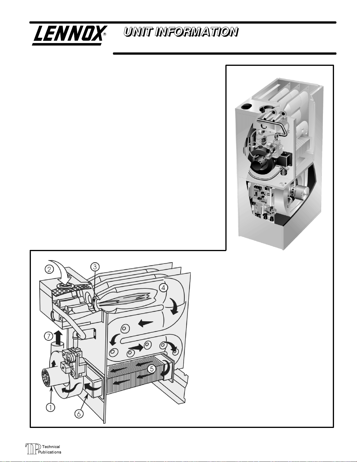
G32V FURNACE
G32V HEAT EXCHANGE ASSEMBLY
Combustion Process:
1. A call for heat starts the combustion air blower.
2. Outdoor air is drawn through pipe into the burner
compartment where it mixes with gas in a conventional style inshot burner.
3. The SureLight ignition system lights the burners.
4. Combustion products are drawn downward
through the heat exchanger. Heat is extracted
as indoor air passes across the outside surface
of the metal.
5. Latent heat is removed from the combustion
products as air passes through the coil. Condensate (water) is formed as the combustion products cool.
6. As the combustion products exit the coil, condensate is collected and drained away.
7. Combustion products are pulled from the heat
exchanger and forced into the flue.
Page 1
© 1998 Lennox Industries Inc.
Litho U.S.A.

TABLE OF CONTENTS
Specifications 3. . . . . . . . . . . . . . . . . . . . . . . . . . . . . . . . .
Blower Data 4. . . . . . . . . . . . . . . . . . . . . . . . . . . . . . . . . .
High Altitude 7. . . . . . . . . . . . . . . . . . . . . . . . . . . . . . . . . .
Venting Table 7. . . . . . . . . . . . . . . . . . . . . . . . . . . . . . . . .
Parts Arrangement 8. . . . . . . . . . . . . . . . . . . . . . . . . . . .
I Unit Components 10. . . . . . . . . . . . . . . . . . . . . . . . . . . .
Control Box 10. . . . . . . . . . . . . . . . . . . . . . . . . . . . . . .
SureLight Ignition System 11. . . . . . . . . . . . . . . . . . .
Two−Stage Ignition Control 13. . . . . . . . . . . . . . . . . .
VSP2−1 14. . . . . . . . . . . . . . . . . . . . . . . . . . . . . . . . . . .
VSP3−1 18. . . . . . . . . . . . . . . . . . . . . . . . . . . . . . . . . . .
SureLight Two Stage Variable Speed Control 22.
Blower Compartment 30. . . . . . . . . . . . . . . . . . . . . . .
Heating 34. . . . . . . . . . . . . . . . . . . . . . . . . . . . . . . . . .
III Start Up 46. . . . . . . . . . . . . . . . . . . . . . . . . . . . . . . . . . . .
IV Heating System Service Checks 47. . . . . . . . . . . . . .
V Typical Operating Characteristics 49. . . . . . . . . . . . . .
VI Maintenance 50. . . . . . . . . . . . . . . . . . . . . . . . . . . . . . .
VII Wiring Diagrams and Operating Sequence 53. . . .
G32V−1 53. . . . . . . . . . . . . . . . . . . . . . . . . . . . . . . . . .
G32V−3 54. . . . . . . . . . . . . . . . . . . . . . . . . . . . . . . . . .
G32V−4 55. . . . . . . . . . . . . . . . . . . . . . . . . . . . . . . . . .
G32V−5 62. . . . . . . . . . . . . . . . . . . . . . . . . . . . . . . . . .
VSP2−1 Jumper Summary 70. . . . . . . . . . . . . . . . . .
VSP3−1 Jumper Summary 74. . . . . . . . . . . . . . . . . .
SureLight Jumper Summary 78. . . . . . . . . . . . . . . .
VIII Troubleshooting 81. . . . . . . . . . . . . . . . . . . . . . . . . . .
VSP2−1 Board 81. . . . . . . . . . . . . . . . . . . . . . . . . . . . .
VSP3−1 Board 82. . . . . . . . . . . . . . . . . . . . . . . . . . . . .
ICM2 Motor with VSP2−1 83. . . . . . . . . . . . . . . . . . .
ICM2 Motor with VSP3−1 84. . . . . . . . . . . . . . . . . . .
ICM2 Motor with SureLight Control 85. . . . . . . . . . .
SureLight Control 86. . . . . . . . . . . . . . . . . . . . . . . . .
II Placement and Installation 38. . . . . . . . . . . . . . . . . . . .
WARNING
Improper installation, adjustment, alteration, service
or maintenance can cause property damage, personal injury or loss of life. Installation and service must
be performed by a qualified installer or service
agency.
WARNING
Electric shock hazard. Can cause injury
or death. Before attempting to perform
any service or maintenance, turn the
electrical power to unit OFF at disconnect switch(es). Unit may have multiple
power supplies.
Page 2
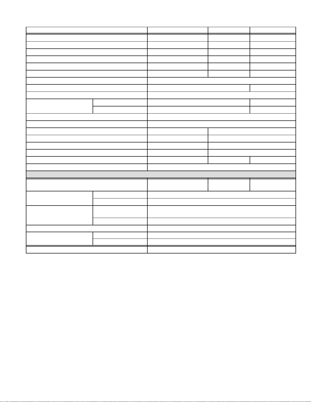
SPECIFICATIONS
Vent/Intake Air Roof
Model No. G32V3−75 G32V5−100 G32V5−125
Input Btuh (kW) − High 75,000 (22.0) 100,000 (29.3) 125,000 (36.6)
Input Btuh (kW) − Low 51,000 (14.9) 68,000 (19.9) 85,000 (24.9)
Output Btuh (kW) − High 67,500 (19.8) 90,000 (26.4) 112,500 (32.9)
Output Btuh (kW) − Low 45,900 (13.4) 61,200 (17.9) 76,500 (22.4)
A.F.U.E. 92.7% 93.2% 94.2%
California Seasonal Efficiency 89.4% 90.1% 91.1%
Exhaust pipe connection (PVC) diameter in. (mm) 2 (51)
Intake pipe connection (PVC) diameter in. (mm) 2 (51) 3 (76)
Condensate drain connection (PVC) in. (mm) 1/2 (12.7)
Temperature rise range F (C)
High static certified by (A.G.A./C.G.A.) in. wg. (Pa) .80 (200)
Gas Piping Size I.P.S. − Natural − in. (mm) 1/2 (12.7)
Blower wheel nominal diameter x width − in. (mm) 10 x 8 (254 x 203) 11−1/2 x 9 (292 x 229)
Blower motor output hp (W) 1/2 1
Nominal cooling that can be added − Tons (kW) 2 to 3 (7 to 10.6) 3−1/2 to 5 (12.3 to 17.6)
No. & size of filters − in. (mm) (1) 14 x 25 x 1 (356 x 635 x 25) (1) 20 x 25 x 1 (508 x 635 x 25)
Shipping weight lbs. (kg) 1 package 161 (73) 201 (91) 221 (100)
Electrical characteristics 120 volts 60 hertz 1 phase (less than 12 amps)
Concentric Vent/Intake Air/Roof Termination Kit 60G77 1/1/2 inch (38 mm)
Vent/Intake Air Roof
Termination Kit vent size
Vent/Intake Air Wall
Termination Kit vent size
Condensate Drain Heat Cable 26K68 6 ft. (1.8 m) − 26K69 24 ft. (7.3 m) − 26K70 50 ft. (15.2 m)
Heat Cable Tape
L.P. Kit 34L29 (−1, −2 models) 11M55 (−3 and later models)
Annual Fuel Utilization Efficiency based on U.S. DOE test procedures and FTC labeling regulations. Isolated combustion system rating for non−weatherized furnaces.
Meets California Nitrogen Oxides (NO
Determine from venting tables proper intake and exhaust pipe size and termination kit required.
Polyurethane frame type filter.
NOTE − 2 inch x 3 inch (51 mm x 76 mm) adaptor is furnished with −100 and −125 furnaces for exhaust pipe connection.
Low Fire 30 − 60(16 − 33) 35 − 65 (19 − 36)
High Fire 40 − 70 (22 − 39) 50 − 80 (28 − 44)
OPTIONAL ACCESSORIES (Must Be Ordered Extra)
33K97 2 inch
(51 mm)
33K97− 2 inch (51 mm)
60L46 − 3 inch (76 mm)
2 inch (51 mm) 15F75
3 inch (76 mm) 44J41
2 inch (51 mm)
15F74 (ring kit) 22G44 (close couple) 30G28 (WTK close couple)
30G79 (WTKX close couple with extension riser)
3 inch (76 mm) 44J40 (close couple) 81J20 (WTK close couple)
Fiberglass − 1/2 in. (38 mm) 39G04
Aluminum foil − 2 in. (25 mm) 39G03
) Standard and California Seasonal Efficiency requirements.
x
Page 3
BLOWER PERFORMANCE
Jumper
g
Setting
ADJUST"
Jumper
Positions
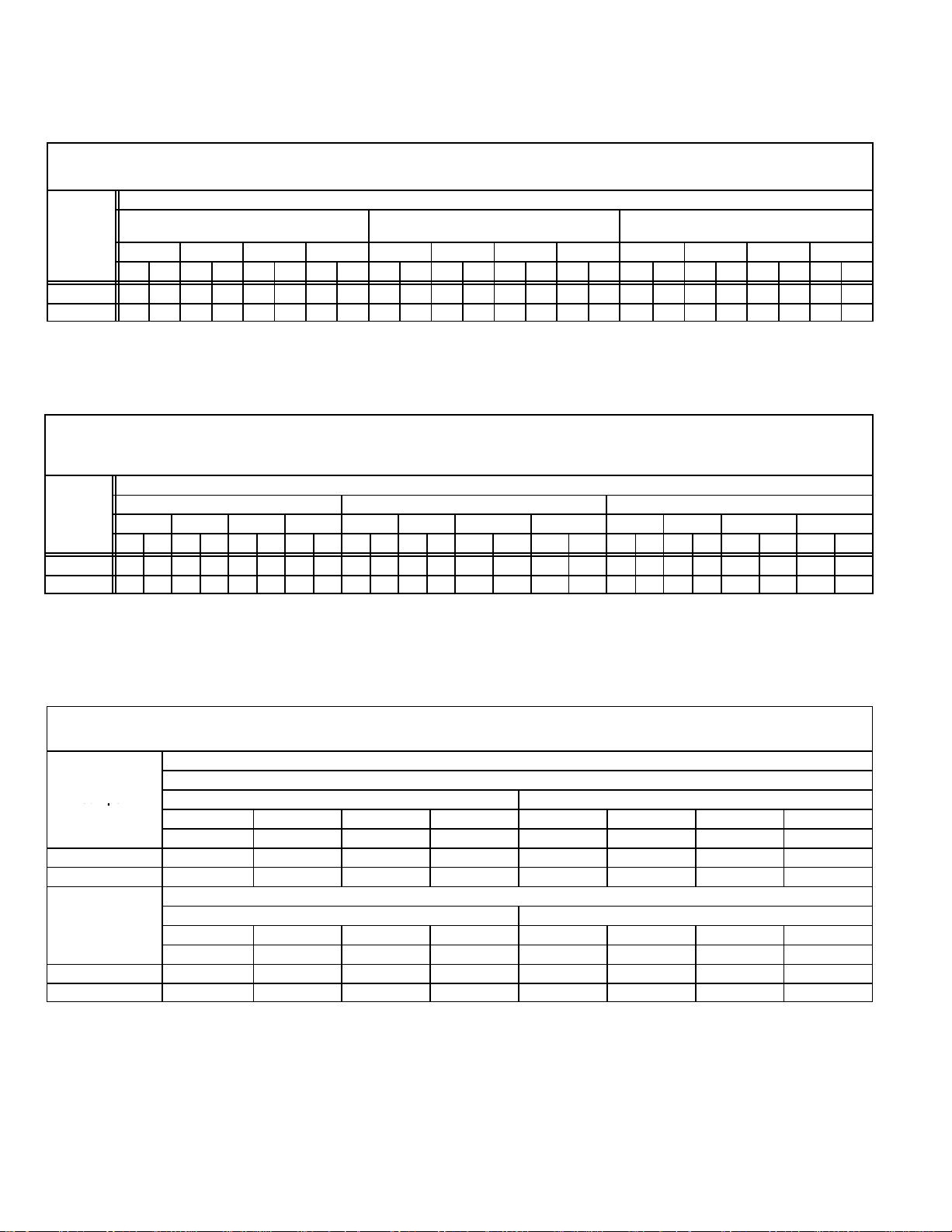
Table 1
G32V3−75−1 through −3 Units
0 THROUGH 0.80 IN. W.G. (0 THROUGH 200 PA) EXTERNAL STATIC PRESSURE
VSP2-1 Blower Control Low Speed 3
Factory Settings High Speed 4
ADJUST"
Jumper
Setting
NORM 880 415 930 440 980 465 1040 490 1060 500 1105 520 1260 595 1330 630 1075 510 1150 545 1270 600 1350 635
− 15% 775 365 810 380 850 400 910 430 930 440 970 460 1070 505 1130 535 930 440 990 465 1080 510 1140 540
NOTE The effect of static pressure and filter resistance is included in the air volumes listed.
(Cool, Low Heat Or Continuous Fan)
1 2 3 4 1 2 3 4 1 2 3 4
cfm L/s cfm L/s cfm L/s cfm L/s cfm L/s cfm L/s cfm L/s cfm L/s cfm L/s cfm L/s cfm L/s cfm L/s
LOW" Speed
0 THROUGH 0.80 IN. W.G. (0 THROUGH 200 PA) EXTERNAL STATIC PRESSURE
VSP2-1 Blower Control G32V5−100 G32V5−125
Factory Settings Low Speed 2 Low Speed 3
ADJUST"
Jumper
Settin
NORM 1140 540 1250 590 1440 680 1550 730 1620 765 1820 860 2000 945 2100 990 1560 735 1720 810 2030 960 2150 1015
NOTE The effect of static pressure and filter resistance is included in the air volumes listed.
G32V5−125 unit only − do not place jumper on tap 1 ("") for high speed or tap 2 ("NORM" or "") for low speed.
LOW" Speed (Cool Or Continuous Fan) HIGH" Speed (Cool) HEAT" Speed
1 2 3 4 1 2 3 4 1 2 3 4
cfm L/s cfm L/s cfm L/s cfm L/s cfm L/s cfm L/s cfm L/s cfm L/s cfm L/s cfm L/s cfm L/s cfm L/s
− 970 460 1060 500 1280 605 1320 625 1380 650 1550 730 1700 800 1780 840 1330 630 1460 690 1730 815 1830 865
Heat Speed 3
VSP2−1 Jumper Speed Positions
HIGH" Speed (Cool) HEAT" Speed
Table 2
G32V5−100/125−1 through −3 Units
High Speed 4 High Speed 4
Heat Speed 1 Heat Speed 2
VSP2 Jumper Speed Positions
Table 3
G32V3−75−4 Units
0 THROUGH 0.80 IN. W.G. (0 THROUGH 200 PA) EXTERNAL STATIC PRESSURE
VSP3−1 Blower Control Factory Settings ADJUST − NORM
Jumper
Positions
NORM (Normal) 880 415 930 440 980 465 1040 490 1075 510 1150 545 1270 600 1350 635
" (Minus) 15% 775 365 810 380 850 400 910 430 930 440 990 460 1080 510 1140 540
ADJUST"
Jumper
Positions
NORM (Normal) 880 415 930 440 980 465 1040 490 1060 500 1105 520 1260 600 1350 635
" (Minus) 15% 775 365 810 380 850 400 910 430 930 440 970 460 1080 510 1140 540
15% lower motor speed than NORM jumper setting.
NOTE − The effect of static pressure and filter resistance is included in air volumes shown.
NOTE − Continuous Fan only speed is approximately 800 cfm (380 L/s) − non adjustable.
NOTE − Lennox Harmony II zone control applications − MAX CFM is determined by COOL jumper placement with a minimum of approximately 850 cfm (400 L/s) for all positions.
"
1 2 3 4 1 2 3 4
cfm L/s cfm L/s cfm L/s cfm L/s cfm L/s cfm L/s cfm L/s cfm L/s
1 2 3 4 1 2 3 4
cfm L/s cfm L/s cfm L/s cfm L/s cfm L/s cfm L/s cfm L/s cfm L/s
Heat Speed − 3
Cool Speed − 4
VSP Jumper Speed Positions
HEAT" Jumper
Low Speed High Speed
COOL" Jumper
Low Speed High Speed
Page 4

Table 4
ADJUST"
Jumper
Positions
Setti
G32V5−100/125−4 Units
0 THROUGH 0.80 IN. W.G. (0 THROUGH 200 PA) EXTERNAL STATIC PRESSURE
VSP3−1 Blower Control Factory Settings G32V5−100 ADJUST − NORM G32V5−125 ADJUST − (minus)
Jumper
Positions
NORM (Normal) 1140 540 1250 590 1440 680 1550 730 1560 735 1720 810 2030 955 2150 1015
" (Minus) 15% 970 455 1060 500 1280 605 1320 595 1330 625 1460 690 1730 815 1830 865
ADJUST"
Jumper
Positions
NORM (Normal) 1140 540 1250 590 1440 680 1550 730 1620 765 1820 860 2000 945 2100 990
" (Minus) 15% 970 455 1060 500 1280 605 1320 595 1380 650 1550 730 1700 800 1780 840
15% lower motor speed than NORM jumper setting.
G32V5−125 Models Only − Do not place jumper on position #1 (at NORM or " setting) or position #2 (at " setting) for HEAT speed.
NOTE − The effect of static pressure and filter resistance is included in air volumes shown.
NOTE − Continuous Fan only speed is approximately 1150 cfm (545 L/s) − non adjustable.
NOTE − Lennox Harmony II zone control applications − MAX CFM is determined by COOL jumper placement with a minimum of approximately 1140 cfm (540 L/s) for all positions.
"
1 2 3 4 1 2 3 4
cfm L/s cfm L/s cfm L/s cfm L/s cfm L/s cfm L/s cfm L/s cfm L/s
1 2 3 4 1 2 3 4
cfm L/s cfm L/s cfm L/s cfm L/s cfm L/s cfm L/s cfm L/s cfm L/s
Low Speed High Speed
Low Speed High Speed
Heat Speed − 2 Heat Speed − 4
Cool Speed − 4 Cool Speed − 4
VSP Jumper Speed Positions
HEAT" Jumper
COOL" Jumper
TABLE 5
G32V3−75−5 Units BLOWER MOTOR PERFORMANCE
0.0" to 0.8" w.g. (0 through 200 Pa) External Static Pressure Range
Blower Speed Adjustment Settings (Switches 5 and 6)
Cool
Adjust"
ng
1 2 3 4 1 2 3 4
cfm L/s cfm L/s cfm L/s cfm L/s cfm L/s cfm L/s cfm L/s cfm L/s
Low Speed High Speed
Norm 880 415 930 440 980 465 1040 490 1060 500 1105 520 1260 595 1330 630
–
775 365 810 380 850 400 910 430 930 440 970 460 1070 505 1130 535
Blower Speed Adjustment Settings (Switches 7 and 8)
Heat
Adjust"
Setting
1 2 3 4 1 2 3 4
cfm L/s cfm L/s cfm L/s cfm L/s cfm L/s cfm L/s cfm L/s cfm L/s
Norm 945 446 1025 484 1125 531 1270 599 1080 510 1172 533 1286 607 1452 685
–
803 379 871 411 956 451 1080 510 918 433 996 470 1093 516 1234 582
15% lower motor speed than NORM switch setting.
NOTE − The effect of static pressure and filter resistance is included in air volumes shown.
NOTE − Continuous Fan only speed is approximately 800 cfm (380 L/s) − non adjustable.
NOTE − Lennox Harmony IIt zone control applications − MAX CFM is determined by COOL switch setting with a minimum of approximately 850
cfm (400 L/s) for all positions.
Low Speed High Speed
Page 5
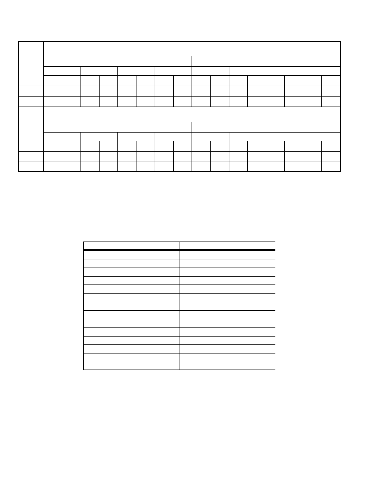
TABLE 6
Setti
G32V5−100/125−5 Units BLOWER MOTOR PERFORMANCE
0.0" to 0.8" w.g. (0 through 200 Pa) External Static Pressure Range
Blower Speed Adjustment Settings (Switches 5 and 6)
Cool
Adjust"
ng
1
cfm L/s cfm L/s cfm L/s cfm L/s cfm L/s cfm L/s cfm L/s cfm L/s
Norm 1140 540 1250 590 1440 680 1550 730 1620 765 1820 860 2000 945 2100 990
–
970 455 1060 500 1280 605 1320 595 1380 650 1550 730 1700 800 1780 840
Low Speed High Speed
2
3 4 1
2
3 4
Blower Speed Adjustment Settings (Switches 7 and 8)
Heat
Adjust"
Setting
1 2 3 4 1 2 3 4
cfm L/s cfm L/s cfm L/s cfm L/s cfm L/s cfm L/s cfm L/s cfm L/s
Norm 1140 540 1250 590 1440 680 1550 730 1560 735 1720 810 2030 960 2150 1015
–
15% lower motor speed than NORM switch setting.
G32V5−125 Models Only − Do not set switches for position #1 (at NORM or –" setting) or position #2 (at −" setting) for HEAT speed.
NOTE − The effect of static pressure and filter resistance is included in air volumes shown.
NOTE − Continuous Fan only speed is approximately 1150 cfm (545 L/s) − non adjustable.
NOTE − Lennox Harmony IIt zone control applications − MAX CFM is determined by COOL switch setting with a minimum of approximately 1140
cfm (540 L/s) for all positions.
970 455 1060 500 1280 605 1320 595 1330 660 1460 690 1730 815 1830 865
Low Speed High Speed
FILTER AIR RESISTANCE
cfm (L/s) in. w.g. (Pa)
0 (0) 0.00 (0)
200 (95) 0.01 (0)
400 (190) 0.03 (5)
600 (285) 0.04 (10)
800 (380) 0.06 (15)
1000 (470) 0.09 (20)
1200 (565) 0.12 (30)
1400 (660) 0.15 (35)
1600 (755) 0.19 (45)
1800 (850) 0.23 (55)
2000 (945) 0.27 (65)
2200 (1040) 0.33 (80)
2400 (1130) 0.38 (95)
2600 (1225) 0.44 (110)
Page 6

No gas pressure adjustment is needed when operating from 0 to 4500 ft. (0 to 8 m). See below for correct manifold pressures for altitudes
greater that 4500 ft. (1372 m) for natural and L.P. gas.
Manifold Absolute Pressure (outlet) in. w.g. (kPa)
Model No.
0 to 4500 ft. (0 to 1372 m)
above sea level
G32V−75 natural no adjustment
G32V−100 natural
G32V−125 natural
3.5 (0.88) 3.4 (0.85) 3.3 (0.82) 3.2 (0.80)
G32V−75 L.P. no adjustment
G32V−100 L.P. 7.5 (0.19) 7.3 (0.185) 7.1 (0.180) 7.0 (0.177)
G32V−125 L.P. 7.5 (0.19) 7.3 (0.185) 7.1 (0.180) 7.0 (0.177)
4501 to 5500 ft.
(1373 to 1676 m)
above sea level
5501 to 6500 ft.
(1677 to 1981 m)
above sea level
6501 to 7500 ft.
(1982 to 2286 m)
above sea level
INTAKE AND EXHAUST PIPE VENTING TABLE
HIGH ALTITUDE INFORMATION
Vent Pipe
Maximum
Equivalent Length
75,000 Btuh (22.0 kW) 100,000 Btuh (29.3 kW) 125,000 Btuh (36.6 kW)
Feet Meters in. mm in. mm in. mm
15 4.6 2 51 2 51 2 51
20 6.1 2 51 2 51 3 76
25 7.6 2 51 2 51 3 76
30 9.1 2 51 3 51 3 76
40 12.2 2 51 3 51 3 76
50 15.2 2 51 3 51 3 76
55 16.8 2 51 3 76 3 76
60 18.3 3 76 3 76 3 76
70 21.3 3 76 3 76 3 76
80 24.4 3 76 3 76 3 76
90 27.4 3 76 3 76 3 76
100 30.5 3 76 3 76 3 76
110 33.5 3 76 3 76 3 76
120 36.6 3 76 3 76 3 76
130 39.6 3 76 3 76 − − − − − − − −
MINIMUM PIPE LENGTHS FOR FURNACES G32V−75 5 feet (1.5 m) with two 90 elbows of 2 inch (51 mm) diameter pipe. (15 equivalent feet (4.6 m) total).
VENTING NOTES One 90elbow is equivalent to 5 feet (1.5 m) of straight vent pipe.
Two 45 elbows are equal to one 90 elbow.
One 45 elbow is equivalent to 2.5 feet (.75 m) of straight vent pipe.
One foot (305 mm) length of 2 in. (51 mm) diameter pipe is equivalent to 8 feet (2.4 m) of 3 in. (76 mm) diameter pipe.
Intake and Exhaust pipes must
2 inch x 3 inch (51 mm x 76 mm) adaptor is furnished with −100 and −125 furnaces for exhaust pipe connection.
Exhaust pipe must terminate with 1−1/2 inch (38 mm) diameter pipe for furnaces using1−1/2 (38 mm) or 2 inch (51 mm) diameter pipe runs.
Exhaust pipe must terminate with 2 inch (51 mm) diameter pipe for furnaces using 3 inch (76 mm) diameter pipe runs.
G32V−100 5 feet (1.5 m) with two 90 elbows of 2 inch (51 mm) diameter pipe. (15 equivalent feet (4.6 m) total).
G32V−125 5 feet (1.5 m) with two 90 elbows of 2 inch (51 mm) diameter pipe. (15 equivalent feet (4.6 m) total).
be the same diameter.
Minimum Vent Pipe Diameter Required
Page 7
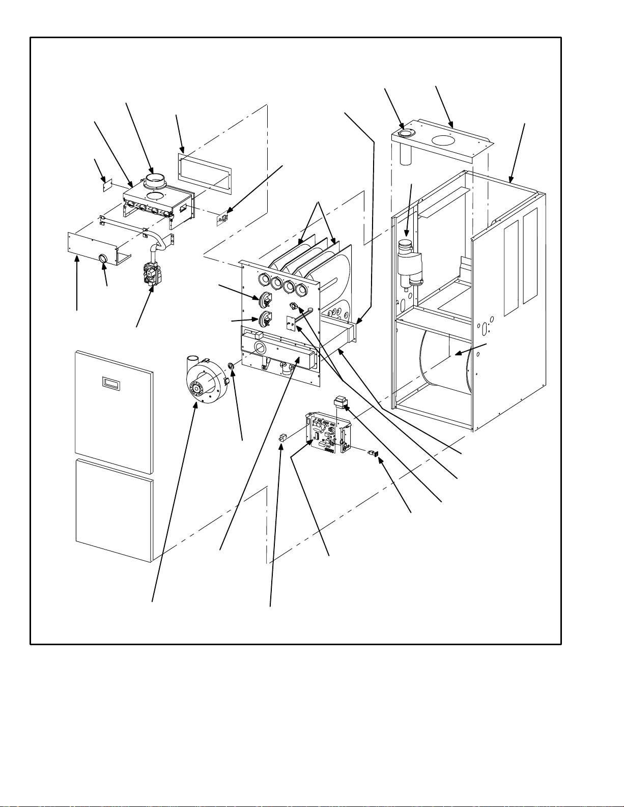
G32V PARTS ARRANGEMENT
FRESH AIR
INTAKE FITTING
BURNER BOX
ASSEMBLY
PATCH
PLATE
FLAME SIGHT
BURNER
BOX
COVER
GLASS
TWO-STAGE
GAS VALVE AND
MANIFOLD
GLASS FIBER GASKET
LOW HEAT
DIFFERENTIAL
PRESSURE
SWITCH
HIGH HEAT
DIFFERENTIAL
PRESSURE
SWITCH
(−75 only)
WARM
HEADER
(COLLECTOR)
BOX
PATCH PLATE WITH
BARBED FITTING
AND FLAME
ROLL−OUT SWITCH
DuralokPlus
HEAT EXCHANGER
ASSEMBLY
TM
FLUE COLLAR
TRANSITION
TOP CAP
CABINET
FLUE
SUPPLY
AIR
BLOWER
BURNER
ACCESS
PANEL
BLOWER
ACCESS
DOOR
TWO−SPEED
COMBUSTION AIR
INDUCER
COMBUSTION
AIR
ORIFICE
COLD HEADER
(COLLECTOR)
BOX
SECONDARY COIL
PRIMARY LIMIT
(ALTERNATE STYLES)
TRANSFORMER
CONTROL VOLTAGE
CIRCUIT BREAKER
SURELIGHT TWO−STAGE,
VARIABLE−SPEED
INTEGRATED CONTROL BOARD
DOOR INTERLOCK SWITCH
FIGURE 1
Page 8

BURNER
ACCESS
COVER
BURNER BOX
MANIFOLD
GAS VALVE
FRESH AIR INTAKE
FITTING
G32V HEAT EXCHANGER
CORBEL ORIFICE
CUPS
SURELIGHT IGNITOR LENNOX DURALOKPLUS
HEAT EXCHANGER ASSEMBLY
COMBUSTION AIR
BLOWER MOTOR
COMBUSTION
AIR BLOWER
BURNER BOX
FLAME SIGHT GLASS
FLUE TRANSITION
LOW HEAT DIFFERENTIAL
PRESSURE SWITCH
HIGH HEAT DIFFERENTIAL
PRESSURE SWITCH
(G32V−75 ONLY)
COMBUSTION AIR BLOWER
DOOR INTERLOCK SWITCH
SURELIGHT CONTROL BOARD*
VSP BLOWER CONTROL BOARD*
BLOWER HOUSING
COLD HEADER
(COLLECTOR )
BOX
G32V GENERAL PARTS ORIENTATION
FIGURE 2
WARM HEADER
CONDENSER COIL
SUPPLY AIR DUCT FLANGE
UPPER VEST PANEL
GAS MANIFOLD
PRIMARY LIMIT
GAS VALVE
COLD HEADER BOX
HEADER BOX
CONDENSATE
LOWER VEST PANEL
CONTROL BOX
CIRCUIT BREAKER
TWO−STAGE CONTROL*
(COLLECTOR)
BOX
TRAP
BLOWER
COMPARTMENT
*NOTE−G32V−1 through −4 units only
BLOWER MOTOR
COIL CHOKE
FIGURE 3
Page 9
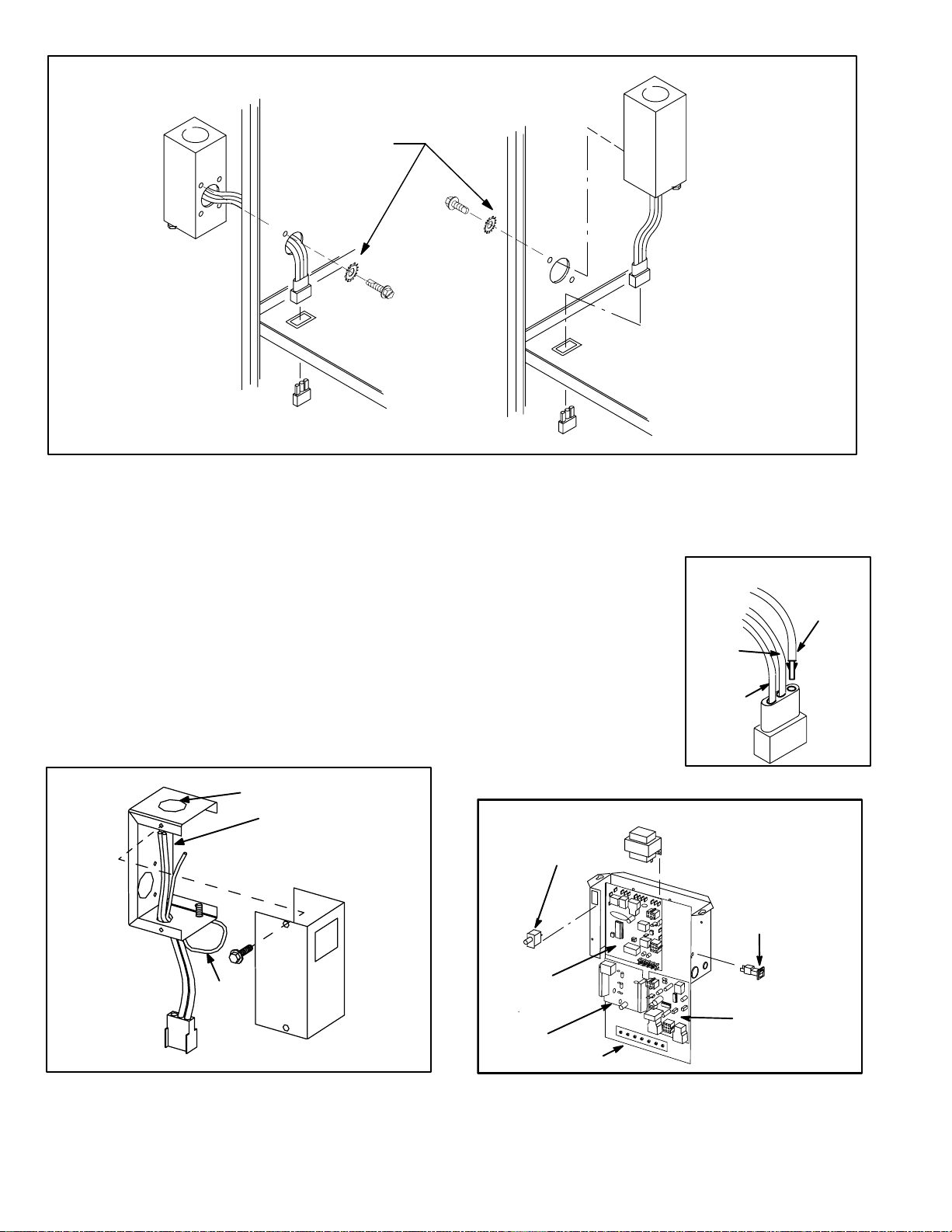
OUTSIDE INSTALLATION
MAKE-UP BOX
MAKE-UP BOX INSTALLATION
Box may be installed inside or outside cabinet and
may be installed on left side or right side of cabinet
STAR WASHERS
MUST BREAK
PAINT ON UNIT
CABINET FOR
PROPER GROUND.
UNIT
CABINET
INSIDE INSTALLATION
MAKE-UP BOX
Line Voltage Enters Through
Knockout In Make-Up Box.
J69 Passes Through Side
Knockout Into Side Of Unit.
JACK J69
BLOWER MULLION
PLUG P69
FIGURE 4
I−UNIT COMPONENTS
G32V unit components are shown in figures 1 and 2. General
parts orientation is shown in figure 3. The gas valve, ignition
control and burners can be accessed by removing the burner
access panel. The blower and blower controls can be accessed by removing the blower access door.
G32V units are designed for bottom and side return air. The
panels are designed to be knocked-out (bottom return) or
cut-out (side return) as required for return air duct connection.
A−Make-Up Box (Figure 5)
The line voltage make-up box is shown in figure 5. The box
may be installed inside or outside the unit and may be installed
on the unit left or right side (figure 4).
MAKE-UP BOX
BOX
POWER ENTRY KNOCKOUT
120V LINE VOLTAGE
PIGTAIL CONNECTIONS
COVER
Line Voltage Enters Make-Up
Box Through Side Of Unit and
J69 Passes Through Bottom
Knockout in Make-Up Box.
BLOWER MULLION
An accessory (brown) output wire is provided with the make-up
box. The wire provides a 120V connection for optional accessories such as electronic air cleaner or humidifier. If used, the
wire is field installed in J69 jack plug by inserting the pin of the
brown wire into the open socket
of the jack. See figure 6. 120V
INSTALLING BROWN
ACCESSORY WIRE TO J69
accessories rated up to 4 amps
total may be connected to this
wire. The neutral leg of the accessory is connected to the
WHITE
NEUTRAL
BROWN
neutral white wire in the makeup box. The accessory terminal
is energized whenever the
blower is in operation.
B−Control Box Components
G32V−1 through −4 CONTROL BOX
DOOR
INTERLOCK
SWITCH
BLACK
J69
FIGURE 6
TRANSFORMER
UNIT
GROUND
JACK J69
to blower deck
Box may be installed inside or outside unit. See Figure 4.
TO BLOWER MULLION
FIGURE 5
SURELIGHT
Page 10
CONTROL
VSP
BOARD
TERMINAL STRIP
FIGURE 7
CIRCUIT
BREAKER
TWO−
STAGE
CONTROL
BOARD

Integrated ignition and blower control components (A92),
unit transformer (T1) and 24V circuit breaker (CB8) are located in the control box. In addition, a door interlock switch
(S51) is located in the control box. Jackplugs allow the control box to be easily removed for blower service.
1. Control Transformer (T1)
A transformer located in the control box provides power to
the low voltage 24volt section of the unit. Transformers on
all models are rated 50VA with a 120V primary and a 24V
secondary.
2. Circuit Breaker (CB8)
A 24V circuit breaker is also located in the control box. The
switch provides overcurrent protection to the transformer
(T1). The breaker is rated 3A . If the current exceeds this limit
the breaker will trip and all unit operation will shut-down. The
breaker can be manually reset by pressing the button on the
face.
3.Door Interlock Switch (S51)
A door interlock switch is located on the control box. The
switch is wired in series with line voltage. When the blower
door is removed the unit will shut down.
ELECTROSTATIC DISCHARGE (ESD)
Precautions and Procedures
NOTE − Do not remove blower access panel to read
SureLight LED lights. A sight glass is provided on the
access panel for viewing.
Tables 9 and 10 show jack plug terminal designations.
Units equipped with the SureLight board can be used with
either electronic or electro−mechanical thermostats without modification. The SureLight ignitor is made of durable
silicon−nitride. Ignitor longevity is also enhanced by voltage ramping by the control board. The board finds the lowest ignitor temperature which will successfully light the
burner, thus increasing the life of the ignitor.
SURELIGHT CONTROL BOARD
CAUTION
Electrostatic discharge can affect electronic
components. Take precautions during furnace
installation and service to protect the furnace’s
electronic controls. Precautions will help to
avoid control exposure to electrostatic discharge by putting the furnace, the control and
the technician at the same electrostatic potential. Neutralize electrostatic charge by touching
hand and all tools on an unpainted unit surface,
such as the gas valve or blower deck, before performing any service procedure.
DANGER
Disconnect power before servicing. Control is not
field repairable. If control is inoperable, simply
replace entire control.
Can cause injury or death. Unsafe operation will
result if repair is attempted.
4.SureLight Ignition System A92
G32V−1 through −4 units are equipped with the Lennox
SureLight ignition system. The system consists of ignition
control board (figure 8 with control terminal designations
in table 1) and ignitor (figure 9). The board and ignitor work
in combination to ensure furnace ignition and ignitor durability. The SureLight integrated board controls all major furnace operations. The board also features two LED lights
for troubleshooting (and two accessory terminals rated at
(4) four amps. See table 8 for troubleshooting diagnostic
codes.
Page 11
13/32’
FIGURE 8
SURELIGHT IGNITOR
MEASUREMENT IS TO I.D.
5/8"
OF RETENTION RING
5/16
"
FIGURE 9

TABLE 7
SURELIGHT CONTROL TERMINAL DESIGNATIONS
ACB COOL NOT USED
ACB HEAT NOT USED
PARK NOT USED
ACB LOW NOT USED
ACC ACCESSORY TERMINAL (LINE VOLT)
TX 120VAC TRANSFORMER
HOT 120VAC HOT INPUT
HTG ACC HEAT ONLY ACCESSORY (LINE VOLT)
NEUTRALS 120VAC NEUTRALS
24VAC HOT 24VAC HOT FROM TRANSFORMER
24VAC RTN 24VAC RETURN FROM TRANSFORMER
FLAME SENSE FLAME SENSE TERMINAL
TABLE 8
DIAGNOSTIC CODES
MAKE SURE TO ID LED’S CORRECTLY: REFER TO INSTALLATION INSTRUCTIONS FOR CONTROL BOARD LAYOUT.
LED #1 LED #2 DESCRIPTION
SIMULTANEOUS
SLOW FLASH
SIMULTANEOUS FAST
FLASH
SLOW FLASH ON
OFF SLOW FLASH
ALTERNATING SLOW
FLASH
SLOW FLASH OFF Flame sensed without gas valve energized.
ON SLOW FLASH Rollout switch open. OR: 9 pin connector improperly attached.
ON
ON
OFF
FAST FLASH SLOW FLASH Main power polarity reversed. Switch line and neutral.
SLOW FLASH FAST FLASH Low flame signal. Measures below .61 microAmps. Replace flame sense rod.
ALTERNATING FAST
FLASH
NOTE − Slow flash equals 1 Hz (one flash per second). Fast flash equals 3 Hz (three flashes per second). Drop out flame sense current < 0.20 microAmps
SIMULTANEOUS
SLOW FLASH
SIMULTANEOUS FAST
FLASH
ALTERNATING SLOW
FLASH
ON
OFF
ON
ALTERNATING FAST
FLASH
Also signaled during cooling and continues fan.
Power − Normal operation
Normal operation − signaled when heating demand initiated at thermostat.
Primary or Secondary limit open. Units with board 63K89 or 24L85: Limit must close within 5
trials for ignition or board goes into one hour limit Watchguard. Units with board 56L83 or
97L48: Limit must close within 3 minutes or board goes into one hour limit Watchguard.
Pressure switch open or has opened 5 times during a single call for heat; OR: Blocked inlet/
exhaust vent; OR: Condensate line blocked; OR: Pressure switch closed prior to activation of
combustion air blower.
Watchguard − burners fail to ignite.
Circuit board failure or control wired incorrectly.
Improper main ground or line voltage below 75 volts; OR: Broken ignitor; OR: Open ignitor
circuit.
TABLE 9
SureLight BOARD J156 TERMINAL
DESIGNATIONS
PIN # FUNCTION
1 Ignitor
2
3
4
Combustion Air Blower Line Voltage
5
6
Combustion Air Blower Neutral
Not Used
Ignitor Neutral
Not Used
Page 12
TABLE 10
SureLight BOARD J58 TERMINAL
DESIGNATIONS
PIN # FUNCTION
1 Primary Limit In
2
3
4
5
6
Pressure Switch and Primary Limit Out
7
8
9
Gas Valve Common
Roll Out Switch Out
Gas Valve 24V
Pressure Switch In
Not Used
Roll Out Switch In
Ground

Electronic Ignition (See Ignition Sequence Below)
On a call for heat the SureLight control monitors the combustion air blower pressure switch. The control will not begin the heating cycle if the pressure switch is closed (by−
passed). Once the pressure switch is determined to be
open, the combustion air blower is energized. When the differential in the pressure switch is great enough, the pressure switch closes and a 15−second pre−purge begins. If the
pressure switch is not proven within 2−1/2 minutes, the control goes into Watchguard−Pressure Switch mode for a
5−minute re−set period.
After the 15−second pre−purge period, the SureLight ignitor
warms up for 20 seconds after which the gas valve opens
for a 4−second trial for ignition. G32V units with board
24L85, 56L83 or 63K89: the ignitor energizes for the first
second of the 4−second trial. Units equipped with board
97L48: ignitor energizes during the trial until flame is
sensed. If ignition is not proved during the 4−second period,
the control will try four more times with an inter purge and
warm−up time between trials of 35 seconds. After a total of
five trials for ignition (including the initial trial), the control
goes into Watchguard−Flame Failure mode. After a 60−minute reset period, the control will begin the ignition sequence
again.
The SureLight control board has an added feature that prolongs the life of the ignitor. After a successful ignition, the
SureLight control utilizes less power to energize the ignitor
on successive calls for heat. The control continues to ramp
down the voltage to the ignitor until it finds the lowest
amount of power that will provide a successful ignition. This
amount of power is used for 255 cycles. On the 256th call
for heat, the control will again ramp down until the lowest
power is determined and the cycle begins again.
5. Two−Stage Control (A86)
G32V−1 through −4 units
G32V−1 through −4 units are equipped with a two−stage
control (figure 10). The two−stage board acts as a go between from the indoor thermostat to the SureLight ignition
board. The board can be utilized in three modes: with a
SINGLE−STAGE thermostat, a TWO−STAGE thermostat or
with a second−stage (high fire) delay called W2 TIMED. The
two−stage board is equipped with a jumper (see figure 10)
which changes operating modes and a jumper which adjusts second−stage heat delay during W2 TIMED mode.
While in the single−stage thermostat mode (one−stage
jumper setting), the unit will always operate on second−
stage heat. The combustion air blower (B6) will operate on
high speed and indoor blower (B3) will operate on heating
speed. While in the two−stage thermostat mode the unit will
operate on first−stage heat (low fire). The combustion air
blower (B6) and indoor blower will operate on low speed.
The unit will switch to second−stage heat (high fire) on call
from the indoor thermostat W2. While in the W2 TIMED
mode (factory setting 8 minutes) the unit will fire on first−
stage heat (low fire) with the combustion air blower (B6)
and indoor blower (B3) operating on low speed. After a set
time delay the unit switches to second−stage heat (high
fire). The combustion air blower and indoor blower also
switch to second−stage heat mode.
Ignition Sequence Board: 63K89, 24L85 and 56L8301
38
Blower On"
Delay
5 SEC80
Post
Purge
ON
OFF
DEMAND
CAB
IGNITOR
GAS VALVE
INDOOR BLOWER
1
Pre −Purge Ignitor Warmup Trial for
15
34
35
Ignition
Ignition Sequence Board 97L4801
1
ON
OFF
DEMAND
CAB
IGNITOR
GAS VALVE
INDOOR BLOWER
*All controls: blower on time will be 45 seconds after gas valve is energized. Blower off time will depend on OFF TIME" Setting.
Pre −Purge Ignitor Warmup
15
34
Trial for
Ignition
38
Blower On"
Delay
5 SEC80
Post
Purge
Page 13
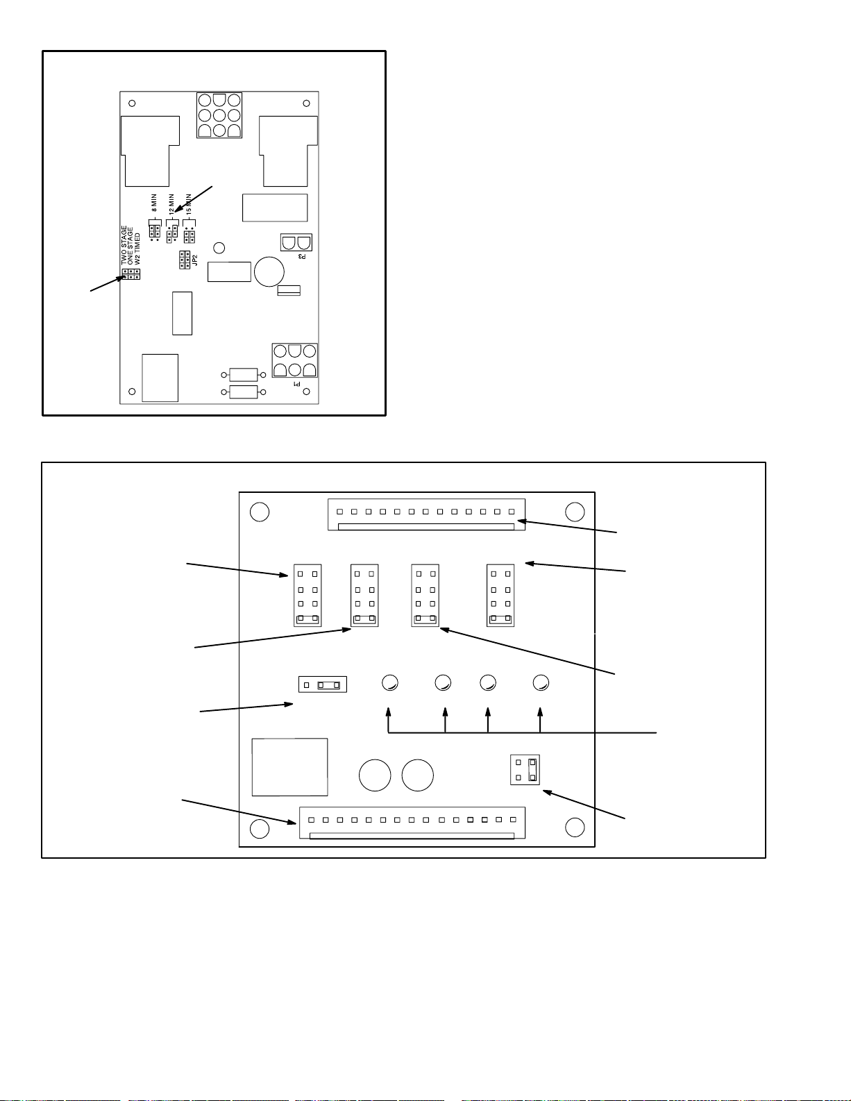
MODE OF
OPERATION
JUMPER
TWO−STAGE CONTROL BOARD
W2 TIMED ON
DELAY JUMPER
FIGURE 10
6.VSP2−1 Blower Control Board (A24)
G32V −1 / −3 units
G32V units are equipped with a variable speed motor that is
capable of maintaining a specified CFM throughout the external static range. The unit uses the VSP2−1 variable
speed control board, located in the blower compartment,
which controls the blower speed and provides diagnostic
LE Ds. The control has bot h a non−adjustable, factory preset
ON" fan timing delay and an adjustable OFF" fan timing delay
(see figure 13).
The VSP2−1 also senses limit trip condition and turns on the
blower. The G32V limit switch is located in the middle of the
vestibule wall. When excess heat is sensed in t h e h e a t exchanger, the limit switch will open and interrupt the current
to the gas valve, while at the same time the VSP2−1 energizes
the blower on heating speed. The limit automatically resets
when the unit temperature returns to normal and the blower is
de−energized.
Diagnostic LEDs located on the VSP2−1 control board are provided to aid in identifying the unit’s mode of operation. Certain
scenarios will arise depending on the jumper positions. Refer
to figure 11 for identification.
HIGH SPEED
SELECTOR PINS
(COOLING ONLY)
LOW SPEED
SELECTOR PINS
(COOLING, HEATING and
CONTINUOUS FAN)
HEATING STAGE
JUMPER SELECTOR PINS
JP73
15 PIN PLUG
(BOARD TO VARIOUS
POINTS IN FURNACE)
VSP2−1 VARIABLE SPEED CONTROL BOARD SELECTIONS
1
JP2
HIGH LOW ADJUST HEAT
TEST
−
+
NORM
DS3
ON/OFF
HI/LOW
DS1
270
1
2
3
4
DS4
CFM
210
90
150
JP1
1
1
2
3
4
HTG.
BLOWER
12
1
2
3
4
HEAT
DS2
FIGURE 11
JP46
13 PIN PLUG
(BOARD TO MOTOR)
HEATING SPEED
SELECTOR PINS
See table 11 for VSP2
factory settings
OPERATIONAL
SELECTOR PINS
(Affects both heating
and cooling modes)
DIAGNOSTIC
DS LEDS
FAN OFF"
TIMING PINS
Page 14

VSP2−1 BLOWER CONTROL BOARD (A24)
1
J46
HIGH LOW ADJUST HEAT
DS3
TEST
−
+
NORM
HI/LOW
1
2
3
4
DS4
1
2
3
4
HTG.
BLOWER
1
2
3
4
HEAT
IMPORTANT
24 VAC half wave rectified (DC pulse), when
measured with a meter, may appear as a lower
or higher voltage depending on the make of the
meter. Rather than attempting to measure the
output voltage of A24, see G32V BLOWER &
VSP2 BLOWER CONTROL BOARD TROUBLESHOOTING FLOW CHART in the TROUBLESHOOTING section of this manual.
DS2
12
J73
1
PIN 2 - G - Input signal from thermostat’s fan signal.
PIN 3 - W2 - Input signal for second stage heat from the thermostat.
PIN 4 - DS - Input signal for the blower speed regulation.
PIN 11 - HT - Input signal from the fan limit control.
PIN 13 - 24V - Input 24 VAC power for the VSP2-1.
PIN 14 - 24V - Input 24 VAC power for the VSP2-1.
PIN 1 - Heat - Heat speed input signal to the ICM2 motor.
PIN 4 - High Tap - High Speed programming input.
PIN 6 - On / Off - On / off output signal to the ICM2 motor.
PIN 8 - Hi / Low - Speed regulate input signal to the ICM2 motor.
PIN 9 - Hi / Low - Speed regulate input signal to the ICM2 motor.
PIN 11 - Heat Tap - Heating blower speed programming.
PIN 1 - C - 24 VAC common.
PIN 5 - Limit - Input signal from the external limit.
PIN 6 - R - 24 VAC power to the thermostat.
PIN 7 - C - 24 VAC common.
PIN 9 - CI - Input signal from the fan limit control.
PIN 10 - CO - Output signal to the burner control.
PIN 5 - Low Tap - Low speed programming input.
Pin 8 - C - 24 VAC common.
PIN 12 - ACC - 24 VAC accessory output.
PIN 15 - V - Input signal from the gas line.
PIN 2 - C - 24 VAC common.
PIN 3 - C - 24 VAC common.
PIN 7 - Adjust Tap - ICM2 mode selection.
PIN 10 - Ref. V - ICM2 reference voltage.
PIN 12 - C - 24 VAC common.
PIN 13 - cfm - Motor speed diagnostic signal.
ON/OFF
J73
J46
DS1
270
CFM
210
90
150
VOLTAGES INTO VSP2−1
Voltage across J73 pins 13 to 1 and 6 to 1 is 24VAC as shown here.
34 volts
0
volts
−34 volts
Voltage across J73 pins 4 to 1 is approximately 15-20VDC (straight voltage)
if CCB is used. If Harmony is used a voltage of 0−25VDC should be present.
If CCB or Harmony is not used, pin 4 to 1 voltage is 21VAC.
Refer to unit wiring diagram.
24VAC @ 60Hz.
VOLTAGES FROM VSP2−1 TO ELECTRONICALLY
CONTROLLED BLOWER MOTOR
Voltage across J46 pins 6 to 3 and 1 to 3 is half-rectified AC as shown here.
Approx.
34 volts
0
volts
Voltage across J46 pins 8 and 9 to 3, is approximately 15-20VDC if CCB is used. If
CCB or Harmony is not used, pins 8 and 9 to 3 voltage is approximately 21VAC. If
Harmony is used a voltage of 0−25VDC should be present.
Refer to unit wiring diagram.
24VAC Half-Rectified (DC
Pulse)
@ 60Hz.
FIGURE 12
Diagnostic LED Lights
a − DS3 ON/OFF"
ON/OFF−DS3 indicates there is a demand for the blower motor
to run. When the ON/OFF LED−DS3 is lit, a demand is being
sent to the motor. In heating mode only, there is a 45 sec o nd
fan ON" delay in energizing ON/OFF LED−DS3. The
light will not go off until adjustable fan OFF" delay has
expired.
If ON/OFF LED−DS3 is on and both HIGH/LOW LED−DS1 &
HEAT LED−DS2 are off, the motor will operate in low
speed.
b − DS2 HEAT"
If HEAT LED−DS2 is on, the blower is running in the heat
speed according to the HEAT" jumper setting. The HEAT
LED−DS2 comes on instantaneous and switches off when
the call for heat is satisfied.
NOTE−When the blower is in OFF" delay mode, the motor runs at low speed, therefore the HEAT LED−DS2 is off. It
switches off when the call for heat is satisfied.
c − DS1 HI/LOW"
HIGH/LOW LED−DS1 indicates whether the blower is oper-
ating in high or low speed. When the light is off, the blower is
running in low speed according to the LOW" jumper setting. When HIGH/LOW LED−DS1 is on, the blower is operating in high speed according to the HIGH" jumper setting.
d − DS4 CFM"
CFM LED−DS4 indicates the CFM the unit is operating, ac-
cording to the jumper settings. The light flashes once for
approximately every 100 CFM. For example, if the unit is
operating at 1000 CFM, CFM LED−DS4 will flash 10 times.
If the CFM is 2050, CFM LED−DS4 will flash 20 full times
plus one fast or half flash.
At times the light may appear to flicker or glow. This takes
place when the control is communicating with the motor between cycles. This is normal operation.
The appropriate speed according to application and CFM
need is selected by moving jumper pins.
Page 15

NOTE−On Harmony II zoning applications in the heating mode,
the highest speed obtainable is the same as the highest cooling speed selection. Also, the heating speed (heat jumper position) is only used when the primary limit has been tripped. In
non−zoning applications, refer to the section on the VSP2−1
control.
When W1 is energized, the LOW jumper selections are activated. The HEAT jumper selections are activated when
W2 is energized.
NOTE−In Harmony II zoning applications, HEATING
BLOWER jumper must be in position #2.
c−HEAT"
Jumper Settings
The HEAT jumper is used to set the blower speed to ob-
tain the required CFM as outlined in HEAT SPEED section of the tables on page 3.
IMPORTANT
Before changing jumper setting, make sure the
motor has completely stopped. Any jumper setting change will not take place while the motor
is running.
To change jumper positions, gently pull the jumper off the pins
and place it on the desired set of pins. The following section
outlines the different jumper selections available and conditions associated with each one. Refer to figure 11 for identification.
After the CFM for each application has been determined, the
jumper settings must be adjusted to reflect those given in
the tables on page 3. Using the tables, determine w h i ch r o w
of CFM volumes most closely matches the desired CFM.
Once a specific row has been chosen (NORMAL or −),
CFM volumes from other rows cannot be used. Below are
the descriptions of each of the jumper selections.
Refer to table 11 for factory settings. Refer to the tables on
page 3 for the approximate air volume for each setting.
TABLE 11
VSP2−1 FACTORY SETTINGS
MODEL
NUMBER
G32V3-75
G32V5-100 241
G32V5-120
HIGH LOW HEAT
3
4
3
ADJUST
NORM
NORM
NORM
24
2
a−ADJUST"
The ADJUST pins allow the motor to run at normal speed or
approximately 15% lower than normal speed. The tables on
page 2 give two rows (NORMAL and −) with their respective
CFM volumes. The + adjustment setting is not operab le.
Notice that the normal adjustment setting for heat speed
position #3 is 2000 CFM (944 L/s). After the adjustment setting has been determined, cho s e th e re m a ining speed
jumper settings from those offered in the table.
The HEAT jumper selections are activated with a call for
second-stage heating (W2).
Before changing jumper setting, make sure the
motor has completely stopped. Any jumper setting change will not take place while the motor is
running.
d−HIGH"
The HIGH jumper is used to determine the CFM during
cooling speed. These jumper selections are activated when
G and DS terminals are energized.
e−LOW"
The LOW jumper is used to determine CFM during low
speed cooling. These jumper selections are activated when
G is energized. The LOW jumper may also be used for low
speed heating. See the HEAT" section for details.
f−FAN OFF"
Fan OFF" timings (time that the blower operates after the
heat demand has been satisfied) are determined by the arrangement of a jumper on the VSP2−1 board. See figure 13.
To adjust fan OFF" timings, gently disconnect the jumper
and reposition it across pins corresponding with the new
timing. Fan OFF" time is adjustable from 90 to 330 seconds. The control has a non−adjustable, factory preset on"
fan timing (45 seconds).
WARNING − MAKE SURE TO DISCONNECT POWER
BEFORE CHANGING FAN OFF" TIMINGS.
TIMING
JUMPER
IMPORTANT
FAN-OFF TIME ADJUSTMENT
To adjust fan−off timings:
Remove jumper from VSP2−1 and
select one of the other pin combinations to achieve the desired
time.
The TEST pin is available to bypass the VSP2−1 control and
run the motor at approximately 70% to test that the m o tor i s
operational. This is beneficial primarily in troubleshooting. G must be energized for motor to run.
b−HEATING BLOWER"
For G32V units, place the HEATING BLOWER jumper
across the second and third pins (position #2).
Page 16
270
150 90
FIGURE 13
210
Leave jumper off to achieve
330 second fan−off timing.
TIMING PINS (seconds)
Fan-off timing is factory
set at 90 seconds
NOTEIf fan OFF" time is too low, residual heat in heat
exchanger may cause primary limit S10 to trip resulting
in frequent cycling of blower. If this occurs, adjust blower
to longer time setting.
in relation to specific modes of operation. Some information has been repeated from the previous section to provide
an example. Refer to each diagnostic LED or jumper settings
section for more information.
Table 12 outlines the operation of the variable speed motor
TABLE 12
VSP2−1 G32V−1 / −3 units OPERATION
HEATING MODE
UNITS WITH
SINGLE−STAGE HEATING
NON−ZONED
APPLICATIONS
Using a single−stage thermostat with
one−stage" heating, the HEAT LED−
DS2 is lit when the thermostat calls for
heat. The ON/OFF LED−DS3 is lit after
110 seconds (65 seconds pre−purge
and 45 seconds fan ON" time) from
the time a call for heat is made. This indicates the blower is operating in heating speed.
Using a single−stage thermostat with
W2 TIMED," and W1 calling, the ON/
OFF LED−DS3 is lit to indicate the
blower is operating on low speed.
When the HEAT LED−DS2 is lit, the
blower is operating in heating speed,
and second−stage (W2) heating is calling.
HARMONY ZONED
APPLICATIONS
The blower speed is controlled by the
PWM (pulse width modulation) signal
sent from the control center of the zoning system to the terminal strip’s DS
terminal. HI/LOW LED−DS1 and ON/
OFF LED−DS3 are lit to indicate the
blower is operating.
NOTE−In Harmony II zoning applications, HTG. BLOWER jumper must be
in position #2.
NOTE: For zone applications with Harmony, remove the wire from the pin #3 of the J73 terminal on the VSP control board, insulate the
end, and secure it to prevent from shorting.
Using a two−stage thermostat with first−
stage (W1) calling, the ON/OFF LED−
DS3 is lit to indicate the blower is operating in low speed.
When the ON/OFF LED−DS3 and
HEAT LED−DS2 are lit, the blower is
operating in heating speed and second−stage (W2) heating is calling.
HEAT LED−DS2 is lit with a call for heat
from the thermostat. ON/OFF LED−
DS3 is lit after 110 seconds from the
time a call for heat is made.
The blower speed is controlled by the
PWM (pulse width modulation) signal
sent from the control center of the zoning system to the terminal strip’s DS
terminal. HI/LOW LED−DS1 and ON/
OFF LED−DS3 are lit to indicate the
blower is operating.
NOTE−In Harmony II zoning applications, HTG. BLOWER jumper must be
in position #2.
UNITS WITH
TWO−STAGE HEATING
NON−ZONED
APPLICATIONS
HARMONY ZONED
APPLICATIONS
UNITS WITH SINGLE−SPEED
COMPRESSOR
NON−ZONED
APPLICATIONS
The terminals DS and Y must be jumpered together. With a call for cooling,
terminals G, Y and DS on the unit control board are energized from the thermostat. HI/LOW LED−DS1 and ON/
OFF LED−DS3 are lit to indicate the
blower is operating on high speed.
NOTEY and DS are factory jumpered for single−stage cooling, non−
zoned.
NOTEFor low speed during single−
stage cooling remove jumper from Y
and Ds.
HARMONY ZONED
APPLICATIONS
The blower speed is controlled by the
PWM (pulse width modulation) signal
sent from the control center of the zoning system to the terminal strip’s DS
terminal. HI/LOW LED−DS1 and ON/
OFF LED−DS3 are lit to indicate the
blower is operating.
COOLING MODE
UNITS WITH TWO−SPEED
The ON/OFF LED−DS3 is lit to indicate
the blower is operating in first stage
cooling. This LED is energized on
when a 24VAC thermostat demand is
supplied to the control (terminal G" on
the control board terminal strip).
In second stage, the ON/OFF LED−
DS3 and HI/LOW LED−DS1 are lit to indicate the blower is operating on high
speed (24VAC is supplied to the unit
terminal strip Y2 from Y2 on the thermostat).
NOTE Jumper must be moved from
Y1 to Y2 In two−speed, non−zoned applications.
HARMONY ZONED
The blower speed is controlled by the
PWM (pulse width modulation) signal
sent from the control center of the zoning system to the terminal strip’s DS
terminal. HI/LOW LED−DS1 and ON/
OFF LED−DS3 are lit to indicate the
blower is operating.
COMPRESSOR
NON−ZONED
APPLICATIONS
APPLICATIONS
Page 17

7.VSP3−1 Blower Control Board (A24)
G32V−4 Units
G32V−4 units are equipped with a variable speed motor that
is capable of maintaining a specified CFM throughout the
external static range. The unit uses the VSP3−1 variable
speed control board, located in the blower compartment,
which controls the blower speed and provides diagnostic
LE Ds. The control has bot h a non−adjustable, factory preset
ON" fan timing delay and an adjustable OFF" fan timing delay
(see figure 13).
Diagnostic LEDs located on the VSP3−1 control board are provided to aid in identifying the unit’s mode of operation. Certain
scenarios will arise depending on the jumper positions. Refer
to figure 14 for identification.
IMPORTANT
The VSP3−1 also senses limit trip condition and turns on the
blower. The G32V limit switch is located in the middle of the
vestibule wall. When excess heat is sensed in t h e h e a t exchanger, the limit switch will open and interrupt the current
to the gas valve, while at the same time the VSP3−1 energizes
the blower on heating speed. The limit automatically resets
when the unit temperature returns to normal and the blower is
de−energized.
VSP3−1 VARIABLE SPEED CONTROL BOARD SELECTIONS
1
JP2
DELAY PROFILE
SELECTOR PINS
(COOLING ONLY)
COOL SPEED
SELECTOR PINS
(COOLING, HEATING and
CONTINUOUS FAN)
HEATING STAGE
JUMPER SELECTOR PINS
DELAY COOL ADJUST HEAT
1
2
3
4
HTG.
BLOWER
12
HEAT
DS2
24 VAC half wave rectified (DC pulse), when measured with a meter, may appear as a lower or
higher voltage depending on the make of the meter. Rather than attempting to measure the output
voltage of A24, see G32V BLOWER & VSP3
BLOWER CONTROL BOARD TROUBLESHOOTING FLOW CHART in the TROUBLESHOOTING
section of this manual.
JP46
13 PIN PLUG
(BOARD TO MOTOR)
1
2
3
4
TEST
−
+
NORM
DS3
ON/OFF
HI/LOW
DS1
1
2
3
4
DS4
CFM
210
HEATING SPEED
SELECTOR PINS
See table 13 for VSP3−1
factory settings
OPERATIONAL
SELECTOR PINS
(Affects both heating
and cooling modes)
DIAGNOSTIC
DS LEDS
JP73
15 PIN PLUG
(BOARD TO VARIOUS
POINTS IN FURNACE)
JP1
270
1
90
150
FAN OFF"
TIMING PINS
FIGURE 14
Page 18

VSP3−1 BLOWER CONTROL BOARD (A24)
1
J46
DELAY COOL ADJUST HEAT
J73
J46
TEST
−
+
NORM
DS3
ON/OFF
HI/LOW
DS1
270
210
150
1
2
3
4
DS4
CFM
90
1
2
3
4
HTG.
BLOWER
12
J73
1
PIN 2 - G - Input signal from thermostat’s fan signal.
PIN 3 - W2 - Input signal for second stage heat from the thermostat.
PIN 4 - DS - Input signal for the blower speed regulation.
PIN 5 - Limit - Input signal from the external limit.
PIN 6 - R - 24 VAC power to the thermostat.
PIN 9 - CI - Input signal from the fan limit control.
PIN 10 - CO - Output signal to the burner control.
PIN 11 - HT - Input signal from the fan limit control.
PIN 12 - ACC - 24 VAC accessory output.
PIN 13 - 24V - Input 24 VAC power for the VSP2-1.
PIN 14 - 24V - Input 24 VAC power for the VSP2-1.
PIN 15 - V - Input signal from the gas line.
PIN 4 - Delay Tap - Delay profile programming input.
PIN 5 - Cool Tap - Cooling blower programming input.
PIN 6 - On / Off - On / off output signal to the ICM2 motor.
PIN 7 - Adjust Tap - ICM2 mode selection.
PIN 9 - Hi / Low - Speed regulate input signal to the ICM2 motor with CCB1 and
PIN 10 - Ref. V - ICM2 reference voltage.
PIN 11 - Heat Tap - Heating blower speed programming.
PIN 13 - cfm - Motor speed diagnostic signal.
1
2
3
4
HEAT
DS2
PIN 1 - C - 24 VAC common.
PIN 7 - C - 24 VAC common.
Pin 8 - C - 24 VAC common.
PIN 1 - Not Used.
PIN 2 - C - 24 VAC common.
PIN 3 - C - 24 VAC common.
PIN 8 - NOT USED
HARMONY only
PIN 12 - C - 24 VAC common.
Diagnostic LED Lights
DS3 ON/OFF
ON/OFF−DS3 indicates there is a demand for the blower
motor to run. When the ON/OFF LED−DS3 is lit, a demand
is being sent to the motor. In heating mode only, there is a
45−second fan ON" delay in energizing ON/OFF LED−DS3.
Light will not go off until adjustable fan OFF" delay has expired.
If ON/OFF LED−DS3 is on and both HIGH/LOW LED−DS1
& HEAT LED−DS2 are off, the motor will operate in low
speed (heating).
DS2 HEAT
If HEAT LED−DS2 is on, the blower is running in second−
stage heat speed according to the HEAT" jumper setting.
In heating mode only, there is a 45 second delay in energizing HEAT LED−DS2. Light will not go off until adjustable fan
OFF" delay has expired.
DS1 HI/LOW
HIGH/LOW LED−DS1 indicates the blower is operating in
the cooling mode.
DS4 CFM
CFM LED−DS4 indicates the CFM the blower is providing,
according to the jumper settings.
Jumper Settings
IMPORTANT
Before changing jumper setting, make sure the
motor has completely stopped. Any jumper setting change will not take place while the motor
is running.
VOLTAGES INTO VSP3−1
Voltage across J73 pins 13 to 1 and 6 to 1 is 24VAC as shown here.
34 volts
0
volts
−34 volts
Voltage across J73 pins 4 to 1 is approximately 15-20VDC (straight voltage)
if CCB is used. If Harmony is used a voltage of 0−25VDC should be present.
If CCB or Harmony is not used, pin 4 to 1 voltage is 21VAC.
Refer to unit wiring diagram.
24VAC @ 60Hz.
VOLTAGES FROM VSP3−1 TO ELECTRONICALLY
CONTROLLED BLOWER MOTOR
Voltage across J46 pins 6 to 3 and 1 to 3 is half-rectified AC as shown here.
Approx.
34 volts
0
volts
Voltage across J46 pin 9 to 3 is approximately 15-20VDC if CCB is used. If CCB or
Harmony is not used, pin 9 to 3 voltage is approximately 21VAC. If Harmony is used
Refer to unit wiring diagram.
a voltage of 0−25VDC should be present.
24VAC Half-Rectified (DC
Pulse)
@ 60Hz.
FIGURE 15
To change jumper positions, gently pull the jumper off the pins
and place it on the desired set of pins. The following section
outlines the different jumper selections available and conditions associated with each one. Refer to figure 14 for identification.
After the CFM for each application has been determined, the
jumper settings must be adjusted to reflect those given in
the tables on page 3 and 4. Using the tables, determine wh i ch
row of CFM volumes most closely matches the desired
CFM. Once a specific row has been chosen (NORMAL or
−), CFM volumes from other rows cannot be used. Below
are the descriptions of each of the jumper selections. Re-
fer to table 13 for factory settings. Refer to CFM tables for
approximate air volume for each setting.
Page 19

TABLE 13
VSP FACTORY SETTINGS FOR G32V−4 UNITS
MODEL
NUMBER
G32V3−75 4 4 NORM 3
G32V5−100 4 4 NORM 2
G32V5−125 4 4 " 4
NOTE − In Harmony II zoning applications in the heating mode, the
highest cooling speed selected is the highest blower speed obtainable. Also, the fan−only speed is used when the primary limit
has been tripped. In non−zoning applications, refer to the section
on the VSP3−1 control.
DELAY COOL ADJUST HEAT
ADJUST
The ADJUST pins allow the motor to run at normal speed or
approximately 15% lower than normal speed. Blower
tables and the front of this manualgive two rows (NORMAL
and −) with their respective CFM volumes. The + adjustment setting is not operable. Notice that the normal adjustment setting for heat speed position #3 is 2030 CFM (955
L/s) in table 4. After the adjustment setting has been determined, choose the remainder speed jumper settings from
those in the table.
The TEST pin is available to bypass the VSP3−1 control and
run the motor at approximately 70% to test that the motor is
operational. This is beneficial primarily in troubleshooting. G
must be energized for motor to run.
HTG. BLOWER
For G32V−4 units only, place the HTG. BLOWER jumper
across the second and third pins (position #2).
NOTE − In Harmony II zoning applications, HTG. BLOWER
jumper must be in position #2.
HEAT
The HEAT jumper is used to set the blower speed to obtain
the required CFM as outlined in HEAT SPEED section of
tables 3 and 4.
The HEAT jumper selections are activated with a call for
first−stage heating (W1) and second−stage heating (W2).
DELAY
The DELAY jumper is used to set the specific motor fan
mode of operation during cooling. Depending on the application, one of four fan options may be chosen by moving
the jumper to the appropriate set of pins.
Options 1, 2, 3, or 4 will have an increased dehumidification
effect on the system. Option 1 will have the least effect and
option 4 will have the greatest effect.
#1 PIN JUMPERED
A − Motor runs at 100% until demand is satisfied.
B − Once demand is met, motor ramps down to off.
A B
100% CFM
COOLING
DEMAND
OFFOFF
#2 PIN JUMPERED
A − Motor runs at 82% for approximately 7−1/2 minutes.
B − If demand has not been satisfied after 7−1/2 minutes,
the motor runs at 100% until demand is satisfied.
C − Once demand is met, motor ramps down to off.
C
OFF
OFF
A
7 1/2 MIN
82%CFM
B
100% CFM
COOLING DEMAND
#3 PIN JUMPERED
A − Motor runs at 50% for 1/2 minute.
B − Motor then runs at 82% for approximately 7−1/2 min-
utes.
C − If demand has not been satisfied after 7−1/2 minutes,
motor runs at 100% until demand is satisfied.
D − Once demand is met, motor ramps down to off.
C D
100% CFM
OFF
OFF
A
1/2 MIN
50% CFM
B
7 1/2 MIN
82% CFM
COOLING DEMAND
#4 PIN JUMPERED
A − Motor runs at 50% for 1/2 minute.
B − Motor then runs at 82% for approximately 7−1/2 min-
utes.
C − If demand has not been satisfied after 7−1/2 minutes,
motor runs at 100% until demand is satisfied.
D − Once demand is met, motor runs at 50% for 1/2 min-
ute.
E − Motor ramps down to off.
C D
100%
CFM
1/2 MIN
50% CFM
E
OFF
OFF
A
1/2 MIN
50% CFM
B
7 1/2 MIN
82% CFM
COOLING DEMAND
COOL
The cool jumper is used to set the blower speed to obtain
the required CFM as outlined in tables 3 and 4.
VSP Operation
Table 14 and 15 outline the operation of the variable speed
motor in relation to specific modes of operation. Some information has been repeated from the previous section to provide an example. Refer to each diagnostic LED or jumper
settings section for more information.
Page 20

TABLE 14
p
Normal operation
blower speed follow thermostat
removal during 1st
ifi
ill i
,
When humidity demand is satisfied
satisfied during
th
gp p
Call f
idit
g
Call for 1st stage
Call for 2nd stage
Reduced blower speed (dehumidifi-
)
mostat demand), slide switch is
G32V−4 UNITS WITH CCB1, & TWO−SPEED OUTDOOR UNIT OPERATING SEQUENCE
Operating Sequence System Demand System Response
System
Condition
Step
Thermostat
Demand
*Relative Humidity
(EfficiencyPlus Lights)
***Compressor
Speed
Blower CFM
(COOL)
Comments
Normal operation
Call for humidity
removal during 1st
stage thermostat
demand
Significant increase
in humidity during
thermostat demand.
Humidity demand
satisfied during
thermostat demand.
or hum
removal during 2nd
stage thermostat
demand
*Call for 1st stage
cooling after call for
humidity removal.
Call for 2nd stage
cooling after call for
humidity removal
Call for cooling after
significant increase
in humidity
Humidity demand
satisfied between
thermostat demands
(unit off cycle).
y
1 Y1 Acceptable (None) Low
2 Y2 Acceptable (None) High HIGH COOL
1 Y1 Acceptable (None) Low
2 Y1
Demand
3
satisfied
4 Y1 Slightly over setpoint (1) High
1 Y1 Acceptable (None) Low
2 Y1
1 Y1 Over Setpoint High
2 Y1
3 None Acceptable (None) Off Off
4 Y1 Acceptable (None) Low
1 Y2 Acceptable (None) High HIGH COOL
2 Y2
3 Y2 Acceptable (None) High HIGH COOL
1 None Slightly over setpoint (1) Off Off Dehumidification mode (high speed
2 Y1 Slightly over setpoint (1) Low
1 None Slightly over setpoint (1) Off Off
2 Y2 Slightly over setpoint (1) High
1 None
2 Y1 or Y2
1 None Over setpoint (1 or more) Off Off
2 Y1 or Y2
Change to slightly
over setpoint (1)
Slightly over setpoint (1) Off Off
Change to significantly
over setpoint (2 or more)
Change to Acceptable
(None)
Change to slightly
over setpoint (1)
Significantly over setpoint
(2 or more)
Significantly over
setpoint (2 or more
Change to
acceptable (None)
Low
High
High HIGH COOL
High
Off Off
High
High HIGH COOL
55% of
HIGH COOL
55% of
HIGH COOL
55% of
HIGH COOL
**77%/74% of
HIGH COOL
55% of
HIGH COOL
**77%/74% of
HIGH COOL
**77%/74% of
HIGH COOL
55% of
HIGH COOL
**77%/74% of
HIGH COOL
55% of
HIGH COOL
**77%/74% of
HIGH COOL
**77%/74% of
HIGH COOL
Compressor demand and indoor
blower s
Dehumidification mode begins with
next thermostat demand, after initial
thermostat demand is satisfied.
If humidity increases significantly
over setpoint, or if slide switch is
moved sign
ately go into dehumidification mode
(in presence of thermostat demand).
When humidity demand is satisfied
blower immediately shifts to the
HIGH COOL CFM in order to hasten
e end of the cycle. Unit can only
shift out of high speed compressor
operation at beginning of next cycle.
Blower immediately changes speed
in response to thermostat demand.
compressor) begins with next ther-
mostat demand after initial demand is
Reduced blower speed (dehumidifi-
cation speed) begins immediately
If humidity increases significantly
over setpoint, or if slide switch is
moved, unit immediately goes into
dehumidification mode (in presence
While unit is not operating (no ther-
mostat demand
moved down and back up. Blower
and compressor operate at high
speed until next thermostat demand.
eed follow thermostat
demand
cantly, unit w
satisfied.
with thermostat demand
of thermostat demand).
, slide switch is
mmedi-
,
Note − When changing unit mode of operation from cooling to heating, indicating lights that are on will stay on until the first thermostat heating demand.
*IMPORTANT - If power to unit is turned on with CCB1 calling for humidity removal, outdoor unit may be locked into high speed
indefinitely. To reset, move humidity slide switch all the way down then back up to desired setpoint (with unit running)
** Reduced blower speed is 77% of COOL for the V3 units; 74% of COOL for V5.
***If the two−speed control on a two−speed outdoor unit is set for LATCH 2 (15 minutes) or LATCH 3 (30 minutes), the compressor
will latch into high speed after a Y1 demand has occurred for that period of time.
Page 21

Heating Mode Cooling Mode
Units With
Single−Stage Heating
Non−Zoned Applications
Using a single−stage thermostat
with "one−stage" heating, the HEAT
LED−DS2 is lit when the thermostat
calls for heat. The ON/OFF LED−
DS3 is lit after 110 seconds (65 seconds prepurge and 45 seconds fan
"ON" time) from the time a call for
heat is made. This indicates the
blower is operating in high speed
heat.
Using a single−stage thermostat
with "W2 TIMED" and W1 calling,
the ON/OFF LED−DS3 is lit to indicate the blower is operating on low
speed heat.
When HEAT LED−DS2 is lit, the
blower is operating in high speed
heat and second−stage (W2) is calling.
G32V−4 Units with VSP3−1
TABLE 15
Units With
Two−Stage Heating
Non−Zoned Applications
Using a two−stage thermostat with
first−stage (W1) calling, the ON/
OFF LED−DS3 is lit to indicate the
blower is operating in low speed
heat.
When the ON/OFF LED−DS3 and
HEAT LED−DS2 are lit, the blower is
operating in high speed heat and
second−stage (W2) is calling.
HEAT LED−DS2 is lit with a call for
heat from the thermostat. ON/OFF
LED−DS3 is after 110 seconds from
the time a call for heat is made.
Units With
Single−speed Compressor
Non−Zoned Applications
Y1−DS and Y1−Y2 must be jumpered together. With a call for cooling, G, Y1, Y2 and DS on the unit
control board are energized from
the thermostat. HI/LOW LED−DS1
and ON/OFF LED−DS3 are lit to indicate a call for cooling.
Note − Y1 to DS and Y1 to Y2 are
factory jumpered for single−stage
cooling, non−zoned applications.
Units With
Two−speed Compressor
Non−Zoned Applications
Y1−DS must be jumpered together.
With a call for single−stage cooling,
G, Y1, and DS on the unit control
board are energized from the Thermostat. With a call for second−stage
cooling, G, Y1, Y2, and DS on the
unit control board are energized
from the thermostat. In both cases,
HI/LOW LED−DS1 and ON/OFF
LED−DS3 are lit to indicate a call for
cooling.
Note − Jumper Y1−Y2 must be removed for units with two−speed
compressor.
Harmony Zoned Applications
The blower speed is controlled by
the PWM (pulse width modulation)
signal sent from the control center
of the zoning system to the terminal
strip’s DS terminal. HI/LOW LED−
DS1 and ON/OFF LED−DS3 are lit
to indicate the blower is operating.
Note − In Harmony II zoning applications, HTG BLOWER jumper must
be in position #2.
Harmony Zoned Application
The blower speed is controlled by
the PWM (pulse width modulation)
signal sent from the control center
of the zoning system to the terminal
strip’s DS terminal. HI/LOW LED−
DS1 and ON/OFF LED−DS3 are lit
to indicate the blower is operating.
Harmony Zoned Application
The blower speed is controlled by
the PWM (pulse width modulation)
signal sent from the control center
of the zoning system to the terminal
strip’s DS terminal. HI/LOW LED−
DS1 and ON/OFF LED−DS3 are lit
to indicate the blower is operating.
NOTE − For zone applications with Harmony, remove the wire from pin #2 and pin #13 of the J49 terminal at the motor and the wire
from pin #3 of the J73 terminal on the VSP control board, insulate the ends and secure to prevent shorting.
8.Two Stage Variable Speed Control (A24)
G32V−5 and later Units
(DS3, DS6, DS7 and DS8) to show furnace status. The
board also has two accessory terminals rated at (1) one
amp each. See table 20 for status code and table 21 for
troubleshooting diagnostic codes.
WARNING
Shock hazard.
Disconnect power before servicing. Integrated
Control Board is not field repairable. If control is
inoperable, simply replace entire control.
Can cause injury or death. Unsafe operation will
result if repair is attempted.
G32V−5 and later units are equipped with the Lennox two−
stage, variable speed integrated SureLight control board.
The system consists of a ignition / blower control board
(figure 16 with control terminal designations in tables 16
through 19) and ignitor (figure 9). The board and ignitor
work in combination to ensure furnace ignition and ignitor
durability. The SureLight integrated board controls all major furnace operations. The board features two LED lights,
DS1 and DS2 for troubleshooting and four LED lights
Electronic Ignition
At the beginning of the heat cycle the SureLight control
monitors the combustion air inducer prove switch. The control will not begin the heating cycle if the prove switch is
closed (by−passed). Once the prove switch is determined to
be open, the combustion air inducer is energized on low
(first stage) heat speed.
G32V−75 Only
At the beginning of the heat cycle the SureLight control
monitors the first and second stage combustion air inducer
prove switches. The control will not begin the heating cycle
if the first stage prove switch is closed (by−passed). Like
wise the control will not begin second stage heat if the second stage prove switch is closed and will allow first stage
heat only. However, if the second stage prove switch closes
DURING first stage pre−purge, the control will still respond
to second stage heat.
Page 22

Once the prove switch (first stage prove switch for
G32V−75) is determined to be open, the combustion air inducer is energized on low (first stage) heat speed. When
the differential in the prove switch is great enough, the
prove switch closes and a 15−second pre−purge begins. If
the switch is not proven within 2−1/2 minutes, the control
goes into Watchguard−Pressure Switch mode for a 5−minute re−set period. After the 15−second pre−purge period, the
SureLight ignitor warms up for 20 seconds after which the
gas valve opens for a 4−second trial for ignition. The ignitor
energizes during the trial until flame is sensed. If ignition is
not proved during the 4−second period, the control will try
four more times with an inter purge and warm−up time between trials of 35 seconds. After a total of five trials for ignition (including the initial trial), the control goes into Watchguard−Flame Failure mode. After a 60−minute reset period,
the control will begin the ignition sequence again.
The SureLight control board has an added feature that prolongs the life of the ignitor. After a successful ignition, the
SureLight control utilizes less power to energize the ignitor
on successive calls for heat. The control continues to ramp
down the voltage to the ignitor until it finds the lowest
amount of power that will provide a successful ignition. This
amount of power is used for 255 cycles. On the 256th call
for heat, the control will again ramp down until the lowest
power is determined and the cycle begins again.
TW0−STAGE, VARIABLE SPEED INTEGRATED
CONTROL BOARD
DIAGNOSTIC
LEDs
DIP
SWITCHES
1 − 3
LEDs
DIP
SWITCHES
5 − 12
LED
Two Stage Operation / Thermostat Selection Jumper
The control can be utilized in two modes: SINGLE−STAGE
thermostat or TWO−STAGE thermostat. The thermostat
selection jumper E20, located just below dip switches 1
through 3 (figure 16), must be positioned for the particular
application. The jumper is factory set on TWO" for use with
a two−stage thermostat with two stage heat. Re−position
jumper to SINGLE" for use with a single stage thermostat
with two stage heat.
While in the single−stage thermostat mode (single jumper
setting), the burners will always fire on first−stage heat. The
combustion air inducer will operate on low speed and indoor blower will operate on low heat speed. After a 10 minute recognition period, the unit will switch to second stage
heat. While in the two−stage thermostat mode (two jumper
setting) the burners will fire on first−stage heat. The combustion air inducer will operate on low speed and indoor
blower will operate on low heat speed. The unit will switch
to second−stage heat on call from the indoor thermostat. If
there is a simultaneous call for first and second stage heat,
the unit will fire an first stage heat and switch to second
stage heat after 30 seconds of operation. See Sequence of
Operation flow charts in the back of this manual for more
detail.
ON−BOARD
ON−BOARD
JUMPER W914
(cut when CCB1 or
Harmony II are used)
THERMOSTAT CONNECTIONS (TB1)
DIP SWITCH FUNCTIONS
DIP SWITCH(ES) FUNCTION
1 and 2 Blower Off Delay
3 Second Stage ON Delay (Single−stage t’stat)
4 Not used
5 and 6 Cooling Mode Blower Speed
7 and 8 Blower Speed Adjustment
9 and 10 Cooling Mode Blower Ramping Profile
11 and 12 Heating Mode Blower Speed
ON−BOARD
JUMPER W915
(cut when two−stage
cooling is used)
JUMPER W951
(cut when heat pump is
used with FM21)
FIGURE 16
Page 23
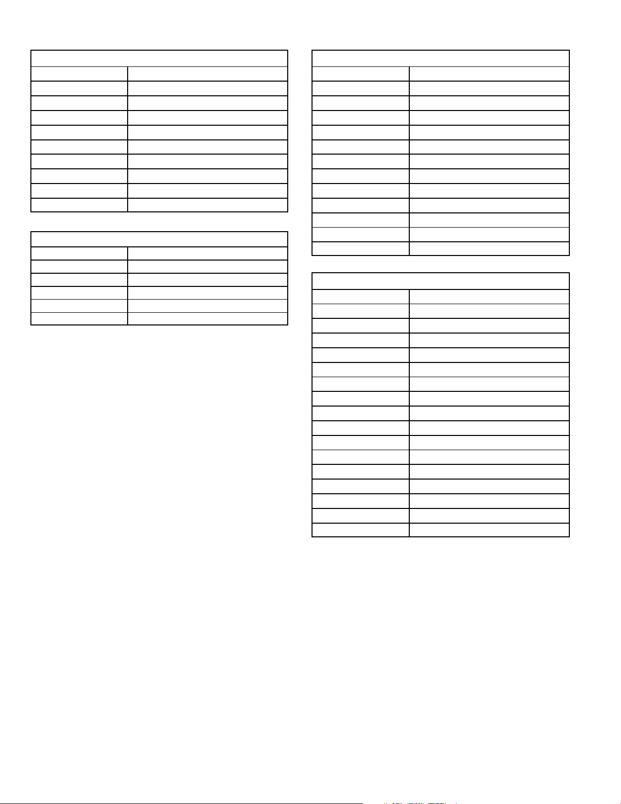
TABLE 16
Two Stage Ignition / Blower Control Terminals
LINE Line 120VAC Neutral
XFMR Transformer 120VAC Neutral
EAC Electronic Air Cleaner 120VAC Neutral
CIRC Indoor Blower 120VAC Neutral
HUM Humidifier 120VAC Neutral
HUM Humidifier 120VAC Hot
XMFR Transformer 120VAC Hot
LINE Line 120VAC Hot
CIRC Indoor Blower 120VAC Hot
EAC Electronic Air Cleaner 120VAC Hot
TABLE 17
SureLight Board 5 Pin Terminal Designation
PIN # Function
1 Ignitor
2 Combustion Air Inducer High Speed
3 Combustion Air Inducer Low Speed
4 Combustion Air Inducer Neutral
5 Ignitor Neutral
TABLE 18
SureLight Board 12Pin Terminal Designation
PIN # Function
1 Gas Valve High Fire
2 Second Stage Prove Switch (G32V−75)
3 Not Used
4 Ground
5 24V Hot
6 Primary Limit In
7 Gas Valve Low Stage
8 Gas Valve Common
9 24V Neutral
10 Ground
11 Primary Limit Out
12 1st Stage Prove Switch
TABLE 19
SureLight Board 16 Pin Blower Control Terminals
PIN # Function
1 Ground
2 Low Heat Speed
3 Ground
4 DELAY" Dip Switch Selection
5 COOL" Dip Switch Selection
6 Y1" Signal
7 ADJUST" Dip Switch Selection
8 Ground
9 0" From Thermostat
10 DS" Output Signal
11 HEAT" Dip Switch Selection
12 24 VAC
13 HIGH HEAT Speed
14 Y2" Signal
15 G"
16 CFM LED
Page 24

TABLE 20
ONONON
Circuit board failure or control wired incorrectly. Check 24 and 115 volts to board.
STATUS CODES
STATUS LED COLOR FUNCTION
DS3
ON / OFF ’
DS6
CFM"
DS7
HI / LO"
DS8
HEAT"
GREEN
GREEN
YELLOW
YELLOW DS8−ON indicates the system is in HEAT mode.
DS3−ON indicates that the motor has a demand to operate. (This LED must be on in all
modes).
DS6−blinking indicates the airflow (CFM) demand in the motor. The air flow is determine by
counting blinks between two (2) second pauses. One blink equals roughly 100 CFM.
DS7−ON indicaties the DS to R" jumper has not been cut. When the jumper is cut the system
will be operating with LENNOX HARMONY II (See Harmony Installation Instructions) or with
the CCB1 Efficiency Plus control.
CCB1: When ON, a 24 VAC is being applied and when OFF, it has been removed. This on/off
operation varies the indoor blower’s performance so dehumidification can be enhanced.
TABLE 21
DIAGNOSTIC CODES
Diagnostic LEDs are labeled DS1 and DS2. See figure 16 for location of diagnostic LEDs.
DS1 DS2 DESCRIPTION
SIMULTANEOUS
SLOW FLASH
SIMULTANEOUS
FAST FLASH
SLOW FLASH ON
OFF SLOW FLASH
OFF FAST FLASH
ALTERNATING
SLOW FLASH
SLOW FLASH OFF Flame sensed without gas valve energized.
ON ON
OFF ON
FAST FLASH SLOW FLASH Main power polarity reversed. Switch line and neutral.
SLOW FLASH FAST FLASH Low flame signal. Measures below 0.23 microAmps. Replace flame sense rod.
ALTERNATING
FAST FLASH
SIMULTANEOUS
SLOW FLASH
SIMULTANEOUS
FAST FLASH
ALTERNATING
SLOW FLASH
OFF
ALTERNATING
FAST FLASH
Power on − Normal operation.
Also signaled during cooling and continuous fan.
Normal operation − signaled when heating demand initiated at thermostat.
Primary, secondary or rollout limit switch open. Limits must close within 3 minutes
or unit goes into 1 hour Watchguard.
Low pressure switch open; (G32V−75 only)
OR: Blocked inlet/exhaust vent;
OR: Low pressure switch closed prior to activation of combustion air inducer.
High pressure switch open;
OR: Blocked inlet/exhaust vent;
OR: High pressure switch closed prior to activation of combustion air inducer.
Watchguard −− burners failed to ignite; OR limit open more than 3 minutes;
OR lost flame sense 5 times in one heating cycle;
OR pressure switch opened 5 times in one heating cycle.
Circuit board failure or control wired incorrectly. Check 24 and 115 volts to board.
The following conditions are sensed during the ignitor warm−up period only:
1) Improper main ground;
2) Broken ignitor; OR: Open ignitor circuit;
3) Line voltage below 75 volts.
(If voltage lower than 75 volts prior to ignitor warm-up, control will signal waiting on
call from thermostat, and will not respond.
NOTE − Slow flash rate equals 1 Hz (one flash per second). Fast flash rate equals 3 Hz (three flashes per second).
Minimum flame sense current = 0.17−0.22 microAmps.
Page 25

Dip Switch Settings
Switches 1 and 2 −− Blower Off Delay −− The blower−on
delay of 45 seconds is not adjustable. The blower−off delay
(time that the blower operates after the heating demand
has been satisfied) can be adjusted by moving switches 1
and 2 on the integrated control board. The unit is shipped
from the factory with a blower−off delay of 90 seconds. The
blower off delay affects comfort and is adjustable to satisfy
individual applications. Adjust the blower off delay to
achieve a supply air temperature between 90° and 110°F at
the exact moment that the blower is de−energized. Longer
off delay settings provide lower supply air temperatures;
shorter settings provide higher supply air temperatures.The table below provides the blower off timings that will
result from different switch settings.
TABLE 22
Blower Off Delay Switch Settings
Blower Off Delay
(Seconds)
Switch 1 Switch 2
60 Off Off
90 Off On
120 On Off
180 On On
Switch 3 −− Second Stage Delay (Used with Single−
Stage Thermostat Only) −− This switch is used to deter-
mine the second stage on delay when a single−stage thermostat is being used. The switch is factory−set in the ON
position, which provides a 10−minute delay before second−
stage heat is initiated. If the switch is toggled to the OFF
position, it will provide a 15−minute delay before second−
stage heat is initiated. This switch is only activated when the
thermostat selector jumper is positioned for SINGLE−stage
thermostat use.
Switch 4 −− Not used.
Switches 5 and 6 −− Cooling Mode Blower Speed −−
Switches 5 and 6 are used to select cooling blower motor
speed. The unit is shipped from the factory with the dip
switches positioned for high speed (4) indoor blower motor
operation during the cooling mode. The table below provides the cooling mode blower speeds that will result from
different switch settings. Refer to blower data tables at the
front of this manual for corresponding cfm values.
TABLE 23
Cooling Mode Blower Speeds
Speed
Switch 5 Switch 6
1 − Low On On
2 − Medium Low Off On
3 − Medium High On Off
4 − High (Factory) Off Off
Switches 7 and 8 −− Blower Speed Adjustment −−
Switches 7 and 8 are used to select blower speed adjustment settings. The unit is shipped from the factory with the
dip switches positioned for NORMAL (no) adjustment. The
dip switches may be positioned to adjust the blower speed
by +10% or −10% to better suit the application. The table below provides blower speed adjustments that will result from
different switch settings. Refer to blower data tables at the
front of this manual for corresponding cfm values.
TABLE 24
Blower Speed Adjustment
Adjustment
Switch 7 Switch 8
+10% (approx.) On Off
NORMAL (Factory) Off Off
−10% (approx.) Off On
Switches 9 and 10 −− Cooling Mode Blower Speed
Ramping −− Switches 9 and 10 are used to select cooling
mode blower speed ramping options. Blower speed ramping may be used to enhance dehumidification performance.
The switches are factory set at option A which has the
greatest effect on blower motor performance. The table below provides the cooling mode blower speed ramping options that will result from different switch settings. The cooling mode blower speed ramping options are detailed on the
next page. See unit nameplate for manufacturing date.
TABLE 25
Cooling Mode Blower Speed Ramping
Ramping Option
Switch 9 Switch 10
A (Factory) Off Off
B On Off
C Off On
D* On On
*Only option for CCB1
Page 26
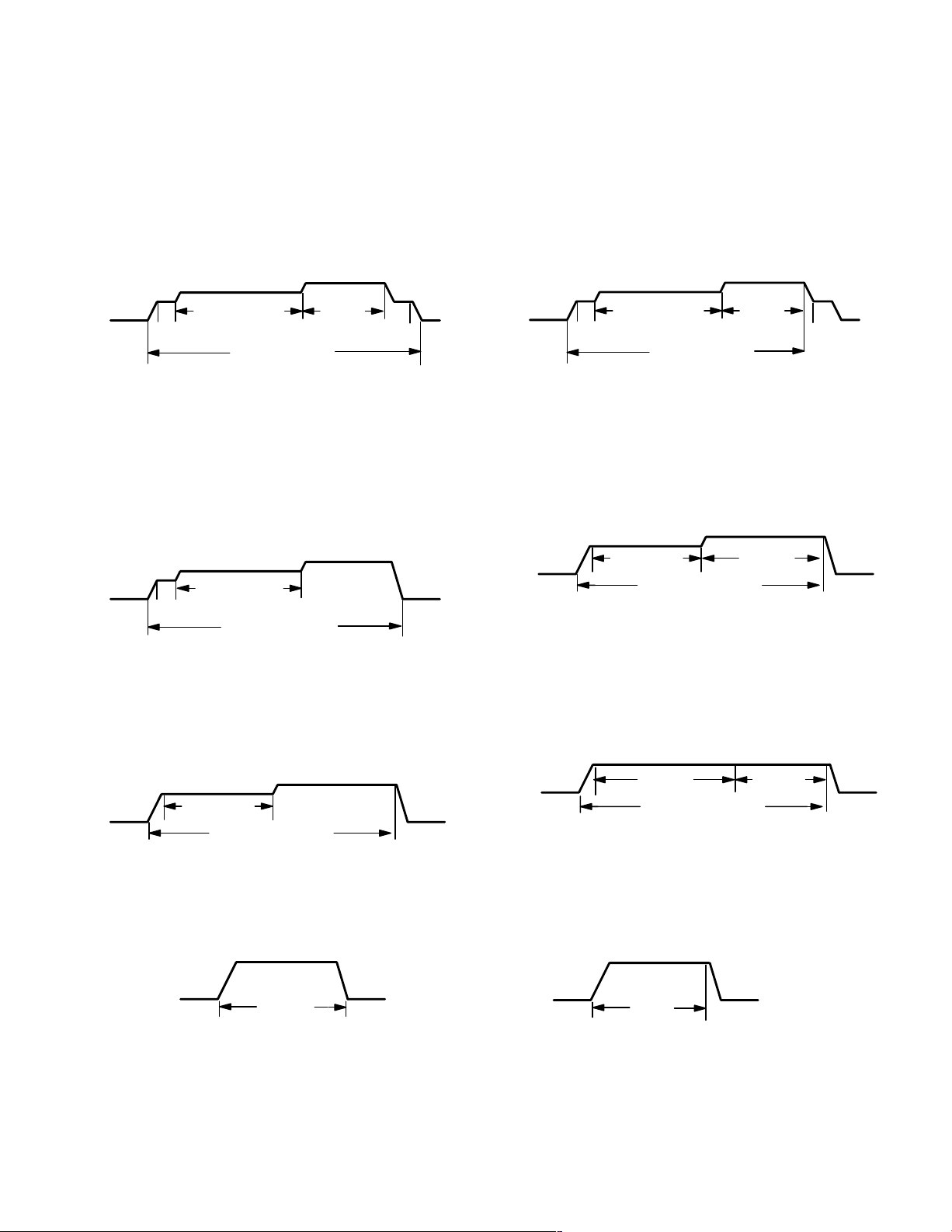
G32V units manufactured before April 2003
Ramping Option A (Factory Selection)
Motor runs at 50% for 1/2 minute.
Motor then runs at 82% for approximately 7−1/2 min-
utes.
If demand has not been satisfied after 7−1/2 minutes,
motor runs at 100% until demand is satisfied.
Once demand is met, motor runs at 50% for 1/2 min-
ute.
Motor ramps down to off.
G32V units manufactured April 2003 and later
Ramping Option A (Factory Selection)
S Motor runs at 50% for 30 seconds.
S Motor then runs at 82% for approximately 7−1/2 min-
utes. If demand has not been satisfied after 7−1/2 minutes.
S Motor runs at 100% until demand is satisfied.
S Once demand is met, motor runs at 50% for 30 seconds
then −
S ramps down to stop.
OFF
1/2 MIN
50% CFM
7−1/2 MIN
82% CFM
COOLING DEMAND
100%
CFM
1/2 MIN
50% CFM
OFF
Ramping Option B
Motor runs at 50% for 1/2 minute.
Motor then runs at 82% for approximately 7−1/2 min-
utes.
If demand has not been satisfied after 7−1/2 minutes,
motor runs at 100% until demand is satisfied.
Once demand is met, motor ramps down to off.
OFF
1/2 MIN
50% CFM
7−1/2 MIN
82% CFM
COOLING DEMAND
100% CFM
OFF
Ramping Option C
Motor runs at 82% for approximately 7−1/2 minutes.
If demand has not been satisfied after 7−1/2 minutes,
the motor runs at 100% until demand is satisfied.
Once demand is met, motor ramps down to off.
OFF
7−1/2 MIN
82%CFM
COOLING DEMAND
100% CFM
OFF
OFF
1/2 MIN
50% CFM
7 1/2 MIN
82% CFM
COOLING DEMAND
100%
CFM
1/2 MIN
50% CFM
OFF
Ramping Option B
S Motor runs at 82% for approximately 7−1/2 minutes. If
demand has not been satisfied after 7−1/2 minutes −
S motor runs at 100% until demand is satisfied.
S Once demand is met, motor ramps down to stop.
OFF
7 1/2 MIN
82%CFM
COOLING DEMAND
100% CFM
OFF
Ramping Option C
S Motor runs at 100% until demand is satisfied.
S Once demand is met, motor runs at 100% for 60 sec-
onds. Then,
S ramps down to stop.
OFF
100% CFM
COOLING DEMAND
100% CFM
OFF
Ramping Option D
Motor runs at 100% until demand is satisfied.
Once demand is met, motor ramps down to off.
100% CFM
COOLING
DEMAND
OFFOFF
Page 27
Ramping Option D
S− Motor runs at 100% until demand is satisfied.
S− Once demand is met, motor ramps down to stop.
100% CFM
COOLING
DEMAND
OFFOFF

Switches 11 and 12 −− Heating Mode Blower Speed −−
idit
Dehumidification mode begins when rela
satisfied between
d
lid
d
Switches 11 and 12 are used to select heating mode blower
motor speed. The unit is shipped from the factory with the
dip switches positioned for medium low (2) speed indoor
blower motor operation during the heating mode. The table
below provides the heating mode blower speeds that will
result from different switch settings. Refer to blower data
tables at the front of this manual for corresponding cfm values.
TABLE 26
Heating Mode Blower Speeds
Speed
Switch 11 Switch 12
1 − Low On On
2 − Medium Low
(Factory)
Off On
3 − Medium High On Off
4 − High Off Off
On−Board Jumper W914
On−board jumper W914, which connects terminals DS and
R on the integrated control board, must be cut when the furnace is installed with either the Harmony II zone control
board or the CCB1 EfficiencyPlus humidity control. Refer to
table 27 for operation sequence in applications including a
G32V, CCB1 and single−speed outdoor unit. Table 28 gives
the operation sequence in applications with a two−speed
outdoor unit.
On−Board Jumper W951
On−board jumper W951, which connects terminals R and O
on the integrated control board, must be cut when the furnace is installed in applications which include a heat pump
unit and the FM21 FuelMaster control board.
On−Board Jumper W915
On board jumper W915, which connects Y1 to Y2 terminals
on the integrated control board terminal strip must be cut if
two−stage cooling will be used.
On−Board Jumper W6
On board jumper W6 is an external measuring device for indoor blower CFM. If by chance W6 is cut, the CFM LED will
not operate but the furnace will operate as normal. The
jumper has no affect on furnace operation.
Diagnostic LEDs (DS1 and DS2)
Two diagnostic LEDs are located on the two−stage, variable
speed integrated control just to the left of the first bank of dip
switches. These lights’ flashes correspond with diagnostic
codes detailed on in table 21.
Status LEDs (HEAT, HI/LO, ON/OFF and CFM)
The integrated control includes four LEDs which indicate
operating status. The green ON/OFF LED is lit any time the
blower is operating. The green CFM LED indicates the
blower motor speed. Count the number of blinks between
the two−second pauses to determine the CFM. Each blink
represents approximately 100 CFM. The yellow HI/LO LED
is lit when the W914 (DS to R) jumper has not
been clipped
for CCB1 or Harmony operation. The yellow HEAT LED is lit
when the indoor blower is operating at the HEATING
speed.
G32V−5, CCB1 and Single−Speed Outdoor Unit
TABLE 27
OPERATING MODE SYSTEM DEMAND SYSTEM RESPONSE
System Condition
Normal operation Y1
*Call for humidity
removal during
cooling demand
Dehumidification
demand satisfied
during cooling demand.
Call for cooling after
call for hum
removal.
Humidity demand
satisfied between
thermostat demands
(unit off cycle).
NOTE − When changing unit mode of operation from cooling to heating, indicating lights that are on will stay on until the first thermostat heating demand.
* Reduced blower speed is 77% of COOL for V3 units and 74% of COOL for the V5 units.
y
Thermostat
Demand
Y1
Y1
None
Y1
None Over setpoint (1 or more) Off
Y1 Change to acceptable COOL
*Relative Humidity
(EfficiencyPlus Lights)
No demand. Humidity
level is acceptable
Humidity level rises
above setpoint. Demand
initiated.
Humidity level falls below
setpoint. No demand
Humidity level above set-
point. Demand initiated.
Humidity level above set-
point. Demand initiated.
Blower
CFM
(COOL)
COOL
77%/74%
of COOL
COOL
Off
77%/74%
of COOL
Comments
Compressor demand and indoor blower
speed controlled by thermostat demand.
Call for dehumidification initiated by CCB1
control. Indoor blower speed reduced by
CCB1 control.
When humidity demand is satisfied, blower speed immediately increases to the
COOL CFM to hasten the end of the cycle.
Dehumidification mode begins when relative humidity is greater than setpoint.
While unit is not operating (no thermostat
emand), s
back up. Blower operates at COOL CFM.
e switch is moved down an
Page 28
 Loading...