

Page 1
INSTALLATION
2002 Lennox Industries Inc.
Dallas, Texas, USA
RETAIN THESE INSTRUCTIONS
FOR FUTURE REFERENCE
INSTRUCTIONS
G32V SERIES UNITS
GAS UNITS
504,564M
5/2002
Supersedes 504,468M
Table of Contents
G32V Unit Dimensions- inches (mm) 2. . . . . . . . . . . .
G32V Parts Arrangement 3. . . . . . . . . . . . . . . . . . . . . .
Safety Instructions 4. . . . . . . . . . . . . . . . . . . . . . . . . . . .
General 5. . . . . . . . . . . . . . . . . . . . . . . . . . . . . . . . . . . . .
Installation - Setting Equipment 5. . . . . . . . . . . . . . . .
Return Air Opening Guidelines 5. . . . . . . . . . . . . . . . .
Filter & Filter Assembly 6. . . . . . . . . . . . . . . . . . . . . . .
Duct System 7. . . . . . . . . . . . . . . . . . . . . . . . . . . . . . . . .
Pipe & Fittings Specifications 7. . . . . . . . . . . . . . . . . .
Vent Piping Guidelines 8. . . . . . . . . . . . . . . . . . . . . . . .
Joint Cementing Procedure 9. . . . . . . . . . . . . . . . . . . .
Venting Practices 9. . . . . . . . . . . . . . . . . . . . . . . . . . . . .
Gas Piping 16. . . . . . . . . . . . . . . . . . . . . . . . . . . . . . . . .
Electrical 17. . . . . . . . . . . . . . . . . . . . . . . . . . . . . . . . . . .
Integrated Control Board Settings 23. . . . . . . . . . . . .
Unit Start-Up 27. . . . . . . . . . . . . . . . . . . . . . . . . . . . . . .
Heating Sequence of Operation 27. . . . . . . . . . . . . . .
Gas Pressure Adjustment 31. . . . . . . . . . . . . . . . . . . .
High Altitude Information 32. . . . . . . . . . . . . . . . . . . . .
Other Unit Adjustments 32. . . . . . . . . . . . . . . . . . . . . .
Service 32. . . . . . . . . . . . . . . . . . . . . . . . . . . . . . . . . . . .
Repair Parts List 35. . . . . . . . . . . . . . . . . . . . . . . . . . . .
Integrated Control Board Diagnostic Codes 35. . . . .
Troubleshooting 36. . . . . . . . . . . . . . . . . . . . . . . . . . . . .
Start-Up & Performance Check List 42. . . . . . . . . . . .
Litho U.S.A.
Do not store or use gasoline or other flamĆ
mable vapors and liquids in the vicinity of
this or any other appliance.
Installation and service must be performed
by a qualified installer, service agency or
the gas supplier.
05/02
*2P0502*
WARNING
If the information in this manual is not
followed exactly, a fire or explosion
may result causing property damage,
personal injury or death.
WHAT TO DO IF YOU SMELL GAS:
Do not try to light any appliance.
Extinguish any open flames.
Do not touch any electrical switch; do not use any
phone in your building.
Leave the building immediately.
Immediately call your gas supplier from a neighbor's
phone. Follow the gas supplier's instructions.
If you cannot reach your gas supplier, call the
fire department.
Page 1
504,564M
*P504564M*
Page 2
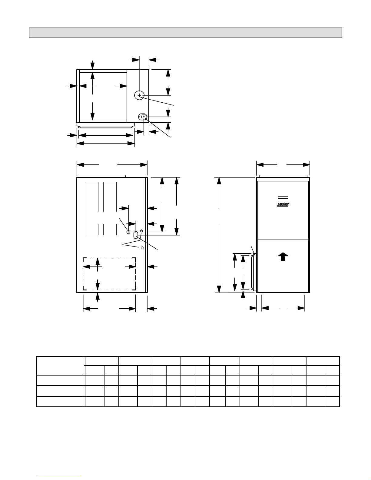
G32V Unit Dimensions - inches (mm)
1 1/16
(41)
5/8
(16)
1 1/16
(41)
18 7/8
(479)
B
SUPPLY
AIR
OPENING
23 3/4 (603)
25 (635)
TOP VIEW
28 1/2
(724)
CONDENSATE
DRAIN
(Both Sides)
ELECTRICAL
INLETS
(Both Sides)
3 5/8
(92)
7 3/8
(187)
2
(51)
2 1/2 (64)
21 3/4
(552)
4 1/2
(114)
GAS PIPING
(Both Sides)
F
COMBUSTION
EXHAUST
AIR OUTLET
23
(584)
INLET
AIR INTAKE
46
(1168)
EXTERNAL
SIDE RETURN
AIR FILTER KIT
(Either Side)
A
(Optional)
23 (584)
C
RETURN AIR
KNOCKOUT
(Either Side)
1-15/16 (49)
23 (584)
Return Air
Knockout (Bottom)
4 (102)
4 (102)
G
5/8 (16)
H
E
AIR FLOW
D
Return Air
Knockout (Bottom)
FRONT VIEWSIDE VIEW
Model No.
G32V3-75 16-1/4 413 14-1/8 359 12 305 12 305 2-1/8 54 7-5/8 194 14 356 12-3/4 324
G32V5–100 21-1/4 540 19-1/8 486 18 457 18 457 1-5/8 41 10-1/8 257 20 508 18-3/4 476
G32V5–125 26-1/4 667 24-1/8 613 18 457 18 457 4-1/8 105 12-5/8 321 20 508 18-3/4 476
A B C D E F G H
in. mm in. mm in. mm in. mm in. mm in. mm in. mm in. mm
Page 2
Page 3
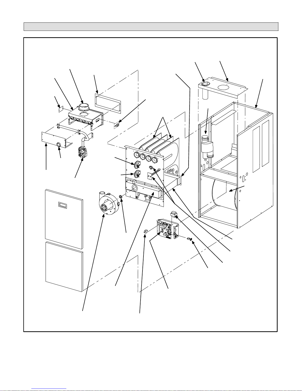
G32V Parts Arrangement
FRESH AIR
INTAKE FITTING
BURNER BOX
ASSEMBLY
PATCH
PLATE
FLAME SIGHT
BURNER BOX
COVER
GLASS
TWOĆSTAGE
GAS VALVE AND
MANIFOLD
GLASS FIBER GASKET
LOW HEAT
DIFFERENTIAL
PRESSURE
SWITCH
HIGH HEAT
DIFFERENTIAL
PRESSURE
SWITCH
(-75 only)
WARM
HEADER
(COLLECTOR)
BOX
PATCH PLATE WITH
BARBED FITTING
AND FLAME
ROLL-OUT SWITCH
DuralokPlus
HEAT EXCHANGER
ASSEMBLY
TM
FLUE COLLAR
TRANSITION
TOP CAP
CABINET
FLUE
SUPPLY
AIR
BLOWER
BURNER
ACCESS
PANEL
BLOWER
ACCESS
DOOR
TWO-SPEED
COMBUSTION AIR
INDUCER
COMBUSTION
AIR
ORIFICE
COLD HEADER
(COLLECTOR)
BOX
SECONDARY COIL
PRIMARY LIMIT
(ALTERNATE STYLES)
TRANSFORMER
CONTROL VOLTAGE
CIRCUIT BREAKER
SURELIGHT TWO-STAGE,
VARIABLE-SPEED
INTEGRATED CONTROL BOARD
DOOR INTERLOCK SWITCH
FIGURE 1
Page 3
Page 4
Safety Instructions
To combustible
Lennox G32V units are Category IV CSA International
certified to ANSI Z21.47 and CSA 2.3 standards.
In the USA, installation of Lennox gas central furnaces
must conform with local building codes. In the absence of
local codes, units must be installed according to the curĆ
rent National Fuel Gas Code (ANSI-Z223.1/NFPA 54) in
the United States. The National Fuel Gas Code is availĆ
able from the following address:
American National Standards Institute, Inc.
11 West 42nd Street
New York, NY 10036
In Canada, installation must conform with current NationĆ
al Standard of Canada CAN/CGAĆB149.1 Installation
Code for Natural Gas Burning Appliances and EquipĆ
ment" and CAN/CGA-B149.2 Installation Code for ProĆ
pane Gas Burning Appliances and Equipment," local
plumbing or waste water codes and other applicable local
codes.
This furnace is CSA International certified for installation
clearances to combustible material as listed on the unit
rating plate and in table 1.
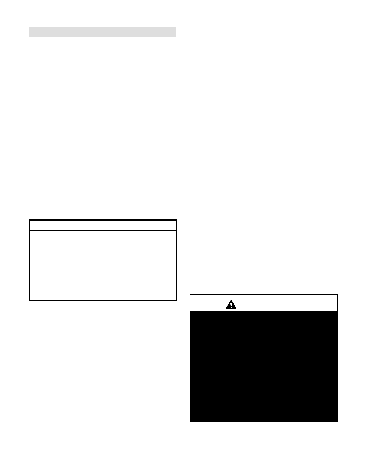
TABLE 1
Clearances Location Inches (mm)
Front 24 (610)
Service access
To combustible
materials
Condensate side
To p 1 (25)
Exhaust 0
Side, rear, and front 0
3 (76)
(from side of unit)
When the furnace is used with cooling units, it shall be
installed in parallel with, or on the upstream side of, cooling units to avoid condensation in the heating compartĆ
ment. With a parallel flow arrangement, a damper (or othĆ
er means to control the flow of air) must adequately
prevent chilled air from entering the furnace. If the dampĆ
er is manually operated, it must be equipped to prevent
operation of either the heating or the cooling unit, unless it
is in the full HEAT" or COOL" setting.
When installed, the furnace must be electrically grounded
according to local codes. In addition, in the United States,
installation must conform with the current National ElecĆ
tric Code, ANSI/NFPA No. 70. The National Electric Code
(ANSI/NFPA No. 70) is available from the following adĆ
dress:
National Fire Protection Association
1 Battery March Park
Quincy, MA 02269
In Canada, all electrical wiring and grounding for the unit
must be installed according to the current regulations of
the Canadian Electrical Code Part I (CSA Standard
C22.1) and/or local codes.
Field wiring connections must meet or exceed specificaĆ
tions of type T wire and withstand a maximum temperaĆ
ture rise of 180°F (82°C).
G32V unit must be installed so that electrical components
are protected from water.
When the furnace is installed so that supply ducts carry
air circulated by the furnace to areas outside of the space
containing the furnace, return air shall be handled by a
duct(s) sealed to the furnace casing and terminating outĆ
side space containing furnace.
Floor 0
NOTE - For installation on combustible floors, the furnace
shall not be installed directly on carpeting, tile, or other
combustible material other than wood flooring.
Accessibility and service clearances must take preceĆ
dence over fire protection clearances.
For installation in a residential garage, the furnace must
be installed so that the burner(s) and the ignition source
are located no less than 18 inches (457 mm) above the
floor. The furnace must be located or protected to avoid
physical damage by vehicles. When a furnace is installed
in a public garage, hangar, or other building that has a
hazardous atmosphere, the furnace must be installed acĆ
cording to recommended good practice requirements
and current National Fuel Gas Code or CAN/CGA B149.1
and B149.2 standards.
WARNING
Product contains fiberglass wool.
Disturbing the insulation in this product during
installation, maintenance, or repair will expose you
to fiberglass wool dust. Breathing this may cause
lung cancer. (Fiberglass wool is known to the State
of California to cause cancer.)
Fiberglass wool may also cause respiratory, skin,
and eye irritation.
To reduce exposure to this substance or for further
information, consult material safety data sheets
available from address shown below, or contact
your supervisor.
Lennox Industries Inc.
P.O. Box 799900
Dallas, TX 75379-9900
Page 4
Page 5
NOTE - G32V series units must not be used as a
construction heater during any phase of construction.
Very low return air temperatures, harmful vapors and misĆ
placement of the filters will damage the unit and lower its
efficiency.
The G32V furnace may be installed in alcoves, closĆ
ets, attics, basements, garages and utility rooms in
the upflow position.
General
The G32V is an upflow gas furnace which is factoryequipped for use with natural gas. A changeover kit is
necessary if the furnace is to be used with L.P. gas. These
instructions are intended as a general guide and do not
supersede local codes in any way. Consult authorities
having jurisdiction before installation.
Shipping and Packing List
1 - Assembled G32V furnace
1 - 3 inch x 2 inch vent transition piece (-100, -125
units only)
1 - Bag assembly containing:
1 - Filter
1 - External filter rack for side return air application
1 - Bag assembly containing:
1 - Electrical make-up box with cover and
grounding screw
4 - Thread-forming make-up box screws
1 - Green ground wire
1 - Wiring harness
1 - Snap bushing
2 - Filter clips
1 - Condensate drain pipe adapter
1 - Condensate plug
4 - Wire nuts
2 - Lockwashers and screws
8 - Self-tapping screws
2 - Filter door pins
1 - Grounding label
1 - Wire tie
Shipping Damage
Check equipment for shipping damage. If you find any
damage, immediately contact the last carrier.
WARNING
Improper installation, adjustment, alteration, serĆ
vice or maintenance can cause property damage,
personal injury or loss of life. Installation and serĆ
vice must be performed by a qualified installer, serĆ
vice agency or the gas supplier.
CAUTION
As with any mechanical equipment, personal injuĆ
ry can result from contact with sharp sheet metal
edges. Be careful when you handle this equipment.
Installation - Setting Equipment
Select a location that allows for required clearances listed
on the unit rating plate. Also consider gas supply connecĆ
tions, electrical supply, vent connection and installation
and service clearances [24 inches (610 mm) at unit front].
The furnace must be level.
CAUTION
G32V unit should not be installed in areas normally
subject to freezing temperatures.
Return Air Opening Guidelines
WARNING
Improper installation of unit can result in personal
injury or death. Combustion and flue products
must never be allowed to enter the return air sysĆ
tem or air in the living space. Use sheet metal
screws and joint tape to seal return air system to
furnace.
In platform installations with furnace return, the
furnace should be sealed airtight to the return air
plenu m . A doo r mu s t never be us e d as a portion of
the return air duct system. The base must provide
a stable support and an airtight seal to the furnace.
Allow absolutely no sagging, cracks, gaps, etc.
For no reason should return and supply air duct
systems ever be connected to or from other heatin g devices such as a fireplace or stove, etc. Fire,
explosion, carbon monoxide poisoning, personal
injury and/or property damage could result.
WARNING
The blower access panel must be securely in place
when the blower and burners are operating. Gas
fumes, which could contain carbon monoxide, can
be drawn into living space resulting in personal inĆ
jury or death.
Return air can be brought in either side or at the bottom of
the unit. Scribe lines show the outline of each side and the
bottom return air opening.
Page 5
Page 6
Bottom Return Air Applications
If return air is to terminate through the floor under the furĆ
nace, a direct, airtight and sealed connection must be
made to the bottom of the furnace.
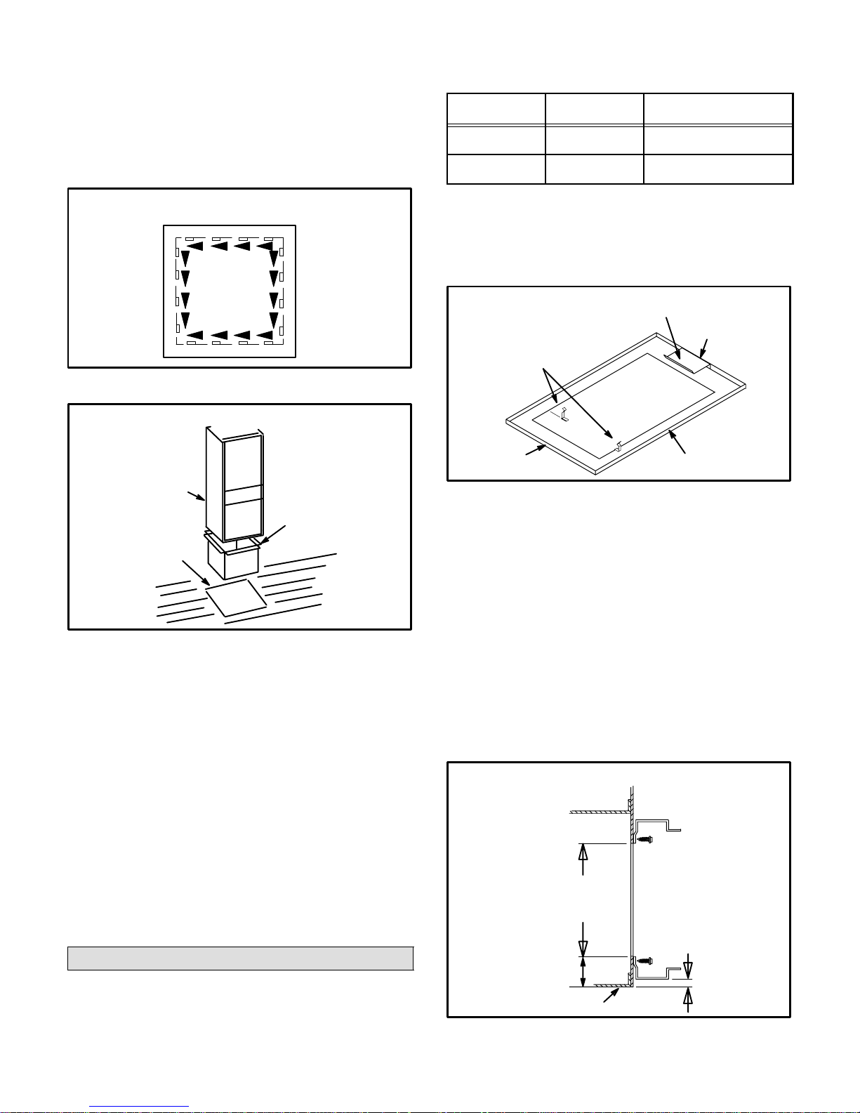
1 - Cut opening in floor or platform. Using knockouts
provided, cut bottom of base panel. See figure 2.
KNOCKOUT PATTERN FOR BOTTOM
RETURN AIR APPLICATION
FIGURE 2
BOTTOM RETURN AIR APPLICATION
FILTER SIZE REQUIREMENTS
TABLE 2
UNIT MODEL
NUMBER
G32V-75 31J81
G32V-100
G32V-125
FILTER PART
NUMBER
P-8-7831
FILTER SIZE
14 inches x 25 inches
(356 x 635 mm)
20 inches x 25 inches
(508 x 635 mm)
Bottom Return Air Applications
1 - Remove blower access panel.
2 - Install filter clips, provided with unit, by slipping
folded section of clip on edge of bottom opening. See
figure 4.
BOTTOM RETURN FILTER INSTALLATION
REAR FILTER CLIP
FURNACE
SIDE FILTER CLIPS (2)
RETURN AIR OPENING
BACK
G32V UNIT
RETURN AIR
PLENUM
PROPERLY
SIZED FLOOR
OPENING
FIGURE 3
2 - Bend a flange on return air plenum and lower into
floor or platform opening. See figure 3.
3 - Position unit over return air opening. Seal unit air
tight with return air plenum.
NOTE - Be careful not to damage insulation. Check for
tight seal.
Side Return Air Applications
For installations where the return air is taken from a return
air drop, unit may be installed using either the left or right
side of furnace.
For side return air applications, cut the furnace cabinet at
the dimensions given in the unit dimensions graphic. EmĆ
bossed corners are pro-vided on both cabinet sides for reĆ
turn air opening location.
FURNACE
FRONT
FURNACE
BASE BOTTOM
FIGURE 4
3 - Place filter in bottom of blower compartment beneath
rear filter clip. Press down on filter sides. Filter clips
flex allowing filter to snap into place.
4 - To remove filter, press clip and pull filter up and out.
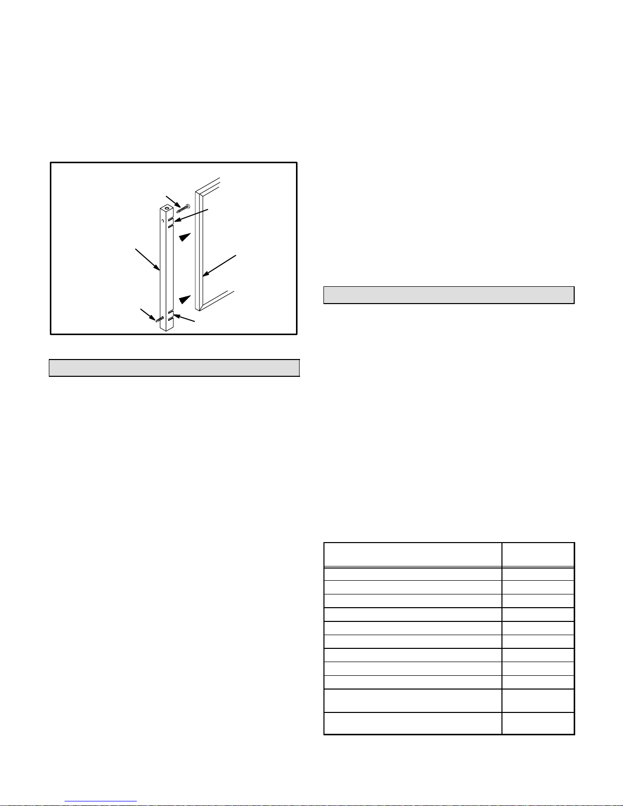
Side Return Air Applications
1 - Align filter rack opening with the inside edge of the
side return opening. Bottom of rack should be
approximately 1 inch (25 mm) from the bottom and 3
inches (76 mm) from the front of the unit.
2 - Screw filter rack into place with the eight self drill, self
tap screws provided. See figure 5.
3 - Push filter door pins through the two holes in filter
door from the inside of the uĆchannel. See figure 6.
SIDE RETURN FILTER INSTALLATION
in. (mm)
BLOWER DECK
RETURN AIR
RETURN
AIR
OPENING
12 in. (305) for
14 in. (356) Filter
18 in. (457) for
20 in. (508) Filter
PLENUM SIZE
12-3/4 in X 23-1/2 in (324 X
597) for 14 in (356) Filter
18-3/4 in. x 23-1/2 in.
(476 x 597)
for 20 in. (508) Filter
Filter & Filter Assembly
A filter and an external filter rack for use in side return air
applications are shipped with the unit. A filter must be in
place anytime the unit is in operation.
Page 6
1-15/16 in.
(49)
CABINET BASE BOTTOM
FIGURE 5
15/16 in
(24)
Page 7
4 - Position filter door on end of filter so that the thumb
tab side of the filter door is away from the furnace.
Squeeze thumb tabs to secure filter to door.
5 - Guide filter and filter door into the filter rack installed
on side of furnace. Push door into filter rack until secure.
6 - To remove filter, pull filter door pins until door is re-
leased from filter rack.
FILTER DOOR ASSEMBLY
FILTER DOOR
PIN
FILTER DOOR
TAB
FILTER
NO TE - For bot to m re tu r n air, ret ur n ai r du ct should be seĆ
cured to the unit using rivets or S-locks. For side return
air, secure return air duct to filter rack using screws. When
using screws, take care to avoid interference with the filĆ
ter which may cause improper filtration.
The ret urn ai r mu s t no t be draw n fro m a room where
another gas appliance (ie., a water heater) is
installed. Even though this furnace draws its combusĆ
tion air from outside of the structure, other gas apĆ
pliances that share a utility room may not. When return
air is drawn from a room, a negative pressure is created
in the room. If a gas appliance is operating in a room
with negative pressure, the flue products can be pulled
back down the vent pipe and into the room. This reverse
flow of the flue gas may result in incomplete combustion
and the formation of carbon monoxide gas. This toxic
gas might then be distributed through the house by the
furnace duct system.
FILTER DOOR
PIN
TAB
FIGURE 6
Duct System
Use industry-approved standards to size and install the
supply and return air duct system. This will result in a quiet
and low-static system that has uniform air distribution. If
the G32V unit is being installed as a replacement for an
existing furnace, the existing supply and return air duct
system should be evaluated to make sure that it is approĆ
priately sized.
The total external static pressure (ESP) should not exĆ
ceed 0.8" w.c. The ESP calculation should include presĆ
sure losses caused by electronic air cleaners, filters,
cooling coils, the duct system, registers and grilles. A
properly sized duct system will help to optimize efficiency
and reliability and to minimize sound levels. Operation of
a G32V unit outside of its specified static pressure range
will result in poor performance and will reduce the useful
life-expectancy of the product and its components.
Supply Air Plenum
Furnaces installed without a cooling coil require the installaĆ
tion of a removable access panel in the supply air duct. The
access panel should be large enough to permit inspection
(either by smoke or reflected light) of the heat exchanger for
leaks after installation. The furnace access panel must alĆ
ways be in place when the furnace is operating and it must
not allow leaks into the supply air duct system.
Return Air Plenum
See dimension illustration for proper return air duct size.
Pipe & Fittings Specifications
All pipe, fittings, primer and solvent cement must conform
with American National Standard Institute and the AmeriĆ
can Society for Testing and Materials (ANSI/ASTM) stanĆ
dards. The solvent shall be free flowing and contain no
lumps, undissolved particles or any foreign matter that
adversely affects the joint strength or chemical resistance
of the cement. The cement shall show no gelation, stratifiĆ
cation, or separation that cannot be removed by stirring.
Refer to table 3 for approved piping and fitting materials.
Primers and solvents must meet ASTM specifications.
PVC primer is specified in ASTM F 656. Use PVC solvent
cement as specified in ASTM D 2564 and ABS solvent
cement as specified in ASTM D 2235. Low temperature
solvent cement is recommended. Metal or plastic strapĆ
ping may be used for vent pipe hangers.
Table 4 lists the available exhaust termination kits. All
Lennox vent terminations are PVC.
TABLE 3
PIPING AND FITTINGS SPECIFICATIONS
PIPE & FITTING MATERIAL
Schedule 40 PVC (Pipe) D1785
Schedule 40 PVC (Cellular Core Pipe) F891
Schedule 40 PVC (Fittings) D2466
Schedule 40 CPVC (Pipe) F441
Schedule 40 CPVC (Fittings) F438
SDR-21 PVC (Pipe) or SDR-26 PVC (Pipe) D2241
SDR-21 CPVC (Pipe) or SDR-26 CPVC (Pipe) F442
Schedule 40 ABS (Pipe) D1527
Schedule 40 ABS (Fittings) D2468
ABS-DWV (Drain Waste & Vent)
(Pipe & Fittings)
PVC-DWV (Drain Waste & Vent Pipe & Fittings)
ASTM
SPECIFICATION
D2661
D2665
Page 7
Page 8

TABLE 4
TERMINATION KITS
Lennox Part
No.
60G77 LB-49107CE
33K97 LB-87942
15F75 LB-49107CC
22G44 LB-49107CD
15F74 LB-49107CB 2" (50.8) Wall Ring Kit
44J41 LB-65678A
44J40 LB-65701A
30G28 WTK
30G79 WTKX
Kit LB# Description-Inches (mm)
1-1/2" (50.8) Concentric
Termination Kit
3" (50.8) Low Pressure Drop ConĆ
centric Term. Kit
2" (50.8) Roof
Termination Kit
2" (50.8) Wall
Assembly Termination Kit
3" (76.2) Roof
Termination Kit
3" (76.2) Wall
Assembly Termination Kit
2" (50.8) Wall
Termination Extended Vent
2" (50.8) Wall
Termination Extension Riser
CAUTION
Solvent cements for plastic pipe are flammable liqĆ
uids and should be kept away from all sources of
ignition. Do not use excessive amounts of solvent
cement when making joints. Good ventilation
should be maintained to reduce fire hazard and to
minimize breathing of solvent vapors. Avoid conĆ
tact of cement with skin and eyes.
When making ABS joints, pieces can be prepared with a
cleaner. When joining ABS to PVC materials, use PVC
solvent cement. Refer to this procedure as specified in
ASTM D3138.
Vent Piping Guidelines
Pipe used for exhaust and intake lines should be sized acĆ
cording to table 5. Note that maximum length of vent pipe
is for one run; either intake or exhaust. Maximum vent
length given is not the total length of intake plus exhaust
vents.
Each 90° elbow is equivalent to 5 feet (1.52 m) of vent
pipe. Two 45° elbows are equivalent to one 90° elbow.
One 45° elbow is equal to 2.5 feet (.76 m) of vent pipe. If
intake and exhaust piping runs are not equal in length and
number of elbows, the larger diameter pipe must be used
for both runs.
TABLE 5
VENT PIPE SIZING TABLE FOR G32V FURNACES
MINIMUM DIAMETER OF INTAKE/EXHAUST PIPE
Vent Pipe
Equivalent Length
Max. Feet (Meters)
15 (4.57) 2" 2" 2"
20 (6.10) 2" 2" 3"
25 (7.62) 2" 2" 3"
30 (9.14) 2" 3" 3"
40 (12.19) 2" 3" 3"
50 (15.24) 2" 3" 3"
55 (16.76) 2" 3" 3"
60 (18.29) 3" 3" 3"
70 (21.34) 3" 3" 3"
80 (24.38) 3" 3" 3"
90 (27.43) 3" 3" 3"
100 (30.48) 3" 3" 3"
110 (33.53) 3" 3" 3"
120 (36.58) 3" 3" 3"
130 (39.62) 3" 3" --
NOTE - Minimum vent pipe for G32V-75, G32V-100, and G32V-125 is 5
feet with 2 elbows of 2-inch diameter pipe.
G32V-75
75,000
BTU
G32V-100
100,000
BTU
G32V-125
125,000
BTU
NOTE - When you install a WTKX termination kit as part
of the intake and exhaust piping, the two 2-inch diameter
90° elbows and the 27 inch pipe (in the kit) should be inĆ
cluded in the maximum vent pipe length for each run.
For 75 kBtuh units, connections are provided for 2-inch
diameter vent pipe which should satisfy most venting reĆ
quirements. No transition pieces are provided or needed
for use with 2-inch vent pipe.
For -100 and -125 kBtuh units, the intake connection is
sized for 3-inch diameter pipe. The exhaust connection
ha s a 2- inc h ni pp le . A pipe transition piece is shipped with
the unit for use with 3-inch pipe. See figure 7 for 2-inch
and 3-inch vent pipe applications.
Most venting applications will require 3-inch vent pipe for
proper unit operation. The intake and exhaust pipe
must never be constructed of different diameter
pipes. Regardless of the diameter of pipe used, the stanĆ
dard roof and wall terminations described in section InĆ
take and Exhaust Piping Terminations should be used.
Exhaust piping must terminate with 1-1/2 inch pipe for
1-1/2 inch or 2 inch vents and 2-inch vent pipe for 3-inch
vents.
Page 8
Page 9
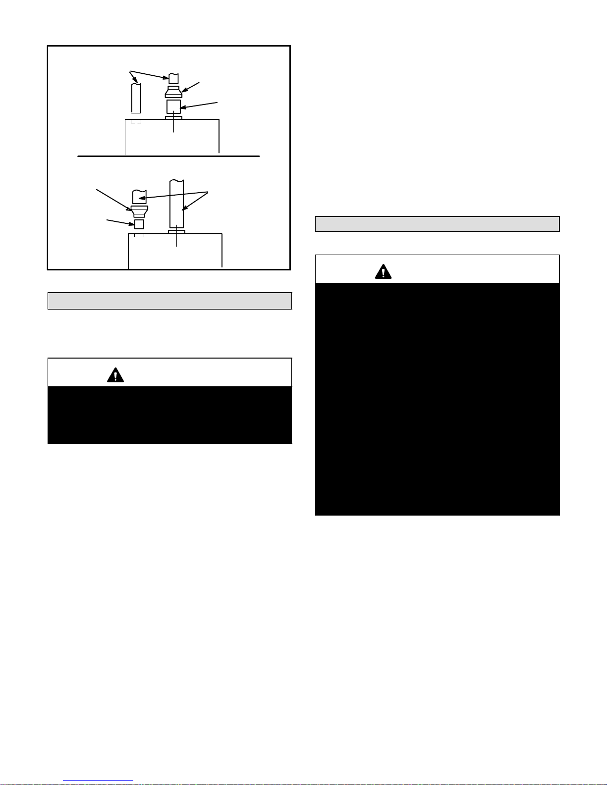
G32V-100 OR -125 WITH 2 IN. VENTING
2 IN. VENT PIPE
2 IN.
OUT
3 IN. X 2 IN.
REDUCER
3 IN.
IN
G32V-100 OR -125 WITH 3 IN. VENTING
3 IN. X 2 IN. REDUCER
2 IN. FIELD
PROVIDED
NIPPLE
2 IN.
OUT
3 IN.
IN
3 IN. FIELD
PROVIDED
NIPPLE
3 IN. VENT PIPE
into socket until it bottoms out. Turn pipe 1/4 turn durĆ
ing assembly (but not after pipe is fully inserted) to
distribute cement evenly.
NOTE - Assembly should be completed within 20 seĆ
conds after last application of cement. Hammer
blows should not be used when inserting pipe.
8 - After assembly, wipe excess cement from pipe at
end of fitting socket. A properly made joint will show a
bead around its entire perimeter. Any gaps may indiĆ
cate a defective assembly due to insufficient solvent.
9 - Handle joints carefully until completely set.
Venting Practices
FIGURE 7
Joint Cementing Procedure
All cementing of joints should be done according to the
specifications outlined in ASTM D 2855.
WARNING
DANGER OF EXPLOSION! Fumes from PVC glue
may ignite during system check. Disconnect wire
from pressure switch terminal before 115 volt powĆ
er is applied to unit. Reconnect wire after two minĆ
utes of combustion air blower operation.
1 - Measure and cut vent pipe to desired length.
2 - Debur and chamfer end of pipe, removing any ridges
or rough edges. If end is not chamfered, edge of pipe
may remove cement from fitting socket and result in
a leaking joint.
3 - Clean and dry surfaces to be joined.
4 - Test fit joint and mark depth of fitting on outside of
pipe.
5 - Uniformly apply liberal coat of PVC primer for PVC or
ABS cleaner for ABS to inside socket surface of fitĆ
ting and male end of pipe to depth of fitting socket.
6 - Promptly apply solvent cement to end of pipe and inĆ
side socket surface of fitting. Cement should be apĆ
plied lightly but uniformly to inside of socket. Take
care to keep excess cement out of socket. Apply
second coat to end of pipe.
NOTE - Time is critical at this stage. Do not allow
primer to dry before applying cement.
7 - Immediately after applying last coat of cement to
pipe, and while both inside socket surface and end of
pipe are wet with cement, forcefully insert end of pipe
WARNING
Insufficient combustion air can cause headaches,
nausea, dizziness or asphyxiation. It will also
cause excess water in the heat exchanger resulting
in rusting and premature heat exchanger failure.
Excessive exposure to contaminated combustion
air will result in safety and performance related
problems. Avoid exposure to the following subĆ
stances in the combustion air supply:
Permanent wave solutions
Chlorinated waxes and cleaners
Chlorine base swimming pool chemicals
Water softening chemicals
De-icing salts or chemicals
Carbon tetrachloride
Halogen type refrigerants
Cleaning solvents (such as perchloroethylene)
Printing inks, paint removers, varnishes, etc.
Hydrochloric acid
Cements and glues
Antistatic fabric softeners for clothes dryers
Masonry acid washing materials
The thickness of construction through which vent/air inĆ
take pipes may be installed is a minimum of 3 inches (76
mm) and a maximum of 24 inches (610 mm). If a G32V
furnace replaces a furnace which was commonly vented
with another gas appliance, the size of the existing vent
pipe for that gas appliance must be checked. Without the
heat of the original furnace flue products, the existing vent
pipe is probably oversized for the single water heater or
other appliance. The vent should be checked for proper
draw with the remaining appliance.
Intake Piping
1 - Cement intake piping in slip connector located at top
of unit.
2 - Route piping to outside of structure. Continue with
installation following instructions given in exhaust
and intake piping termination section.
Page 9
Page 10
Exhaust Piping
1 - Cement exhaust piping into flue collar socket located
on the left side of the top cap.
2 - All horizontal runs of exhaust pipe must slope back
toward the unit. A minimum of 1/4 inch (6 mm) drop
for each 12 inches (305 mm) of horizontal run is manĆ
datory for drainage. Horizontal runs of exhaust pipĆ
ing must be supported every 5 feet (1.52 m) using
hangers.
NOTE - Exhaust piping should be checked carefully
to make sure there are no sags or low spots.
NOTE - Exhaust piping must be insulated with 1/2
inch (13 mm) Armaflex or equivalent when run
through unheated space. Do not leave any area of
exhaust pipe open to outside air; exterior exhaust
must be insulated with 1/2 inch (13 mm) Armaflex or
equivalent.
CAUTION
Do not discharge exhaust into an existing stack or
stack that also serves another gas appliance. If verĆ
tical discharge through an existing unused stack is
required, insert PVC pipe inside the stack until the
end is even with the top or outlet end of the metal
stack.
CAUTION
The exhaust vent pipe operates under positive
pressure and must be completely sealed to prevent leakage of combustion products into the livĆ
ing space.
Removal of Unit from Common Venting System
In the event that an existing furnace is removed from a
venting system commonly run with separate gas apĆ
pliances, the venting system may be too large to properly
vent the remaining attached appliances. The following
test should be conducted while all appliances (both in opĆ
eration and those not in operation) are connected to the
common venting system. If the venting system has been
installed improperly, corrections must be made as outĆ
lined in the previous section.
1 - Seal any unused openings in the common venting
system.
2 - Visually inspect the venting system for proper size
and horizontal pitch and determine there is no blockĆ
age or restriction, leakage, corrosion or other defiĆ
ciencies which could cause an unsafe condition.
3 - Close all building doors and windows, and all doors
between the space in which the appliances remainĆ
ing connected to the common venting system are loĆ
cated and other spaces of the building. Turn on
clothes dryers and any appliances not connected to
the common venting system. Turn on any exhaust
fans, such as range hoods and bathroom exhausts,
so they will operate at maximum speed. Do not operĆ
ate a summer exhaust fan. Close fireplace dampers.
4 - Follow the lighting instructions. Place the appliance
being inspected in operation. Adjust thermostat so
appliance will operate continuously.
5 - Test for spillage at the draft hood relief opening after
5 minutes of main burner operation. Use the flame of
match or candle, or smoke from a cigarette or cigar,
or a draft gauge.
6 - After determining that each appliance remaining
connected to the common venting system properly
vents when tested as indicated in step 3, return
doors, windows, exhaust fans, fireplace dampers
and any other gasĆburning appliance to their preĆ
vious condition of use.
7 - If improper venting is observed during any of the
above tests, the common venting system must be
corrected. The common venting system should be
resized to approach the minimum size as deterĆ
mined by using the appropriate tables in appendix G
in the current standards of the National Fuel Gas
Code ANSI Z223-1 in the USA, and the appropriate
Category 1 Natural Gas appliances venting sizing
tables in the current standard of the CAN/
CGA-B149.1 in the Natural Gas Installation Code in
Canada.
Intake and Exhaust Piping Terminations
Intake and exhaust pipes may be routed either horizontalĆ
ly through an outside wall or vertically through the roof. In
attic or closet installations, vertical termination through
the roof is preferred. Figures 8 through 20 show typical
terminations.
1 - Use recommended piping materials for both intake
and exhaust piping.
2 - Secure all joints, including drain leg, gas-tight using
approved cement.
3 - Piping diameters should be determined according
to length of pipe run. See table 5. Locate intake pipĆ
ing upwind (prevailing wind) from exhaust piping.
To avoid recirculation of exhaust gas on roof terĆ
minations, end of exhaust pipe must be higher than
intake pipe.
Exhaust and intake exits must be in same pressure
zone. Do not exit one through the roof and one on the
side. Also, do not exit the intake on one side and the
exhaust on another side of the house or structure.
Page 10
Page 11

4 - Intake and exhaust pipes should be placed as close
together as possible at termination end (refer to ilĆ
lustrations). Maximum separation is 3 inches (76
mm) on roof terminations and 6 inches (152 mm) on
side wall terminations.
5 - Exhaust piping must terminate straight out or up as
shown. In rooftop applications, a 2 inch X 1-1/2 inch
reducer for 2 inch venting, 3 inch x 2 inch reducer for
3 inch venting must be used on the exhaust piping at
the point where it exits the structure to improve the
velocity of exhaust away from the intake piping.
On roof terminations, the intake piping should termiĆ
nate straight down using two 90° elbows. See figure 8.
Inches (mm)
8 (203) MIN
12 (305) ABOVE
AVERAGE SNOW
ACCUMULATION
3 (76) MAX.
3 x 2 (76 x 51) OR
2 x 1-1/2 (51 x 38)
PVC REDUCER
1/2 (13) FOAM
INSULATION IN
UNCONDITIONED
SPACE
NOTE - During extremely cold temperatures, below
approximately 20°F (6.67°C), units with long runs of
vent pipe through unconditioned space, even when inĆ
sulated, may form ice in the exhaust termination that
prevents the unit from operating properly. Longer run
times of at least 5 minutes will alleviat e mos t icing probĆ
lems. Also, a heatin g cable may be installed on exhaust
piping and termination to prevent freezeĆups. Heating
cable installation kit is available from Lennox. See ConĆ
densate Piping section for part numbers.
NOTE - Avoid recirculation of exhaust back into the inĆ
take pipe.
6 - On field-supplied terminations for side wall exits, exĆ
haust piping should extend a maximum of 12 inches
(305 mm) beyond the outside wall. Intake piping
should be as short as possible. See figure 9.
1/2 (13) ARMAFLEX
INSULATION IN
UNCONDITIONED SPACE
2 (51) PVC 1-1/2 (38) PVC
12 (305) MIN.
2 X 1-1/2
(51 x 38)
PVC REDUCER
3 (76) OR
2 (51) PVC
PROVIDE SUPPORT
FOR INTAKE AND
EXHAUST LINES
ROOF TERMINATION KIT
(15F75) LB-49107CC for 2 (51) Venting
(44J41) LB-65678A for 3 (76) Venting
UNCONDITIONED
ATTIC SPACE
FIGURE 8
IMPORTANT
Do not use screens or perforated metal in intake
and exhaust terminations. Doing so will cause
freeze-ups and may block the terminations.
NOTE - If winter design temperature is below 32°F (0°C),
exhaust piping must be insulated with 1/2 inch (13 mm),
Armaflex or equivalent when run through unheated
space. Do not leave any surface area of exhaust pipe
open to outside air; exterior exhaust pipe must be insuĆ
lated with 1/2 inch (13 mm) Armaflex or equivalent. In exĆ
treme cold climate areas, 3/4 inch (19 mm) Armaflex or
equivalent is recommended. Insulation on outside runs of
exhaust pipe must be painted or wrapped to protect inĆ
sulation from deterioration.
1/2 (13) ARMAFLEX
Inches (mm)
INSULATION
OUTSIDE
WALL
TOP VIEW
(15J74) LB-49107CB for 2 (50.8) Venting
WALL RING KIT
6 (152)
MAXIMUM
8 (203)
MINIMUM
2 (51) PVC
COUPLING
FIGURE 9
7 - On field-supplied terminations, a minimum separaĆ
tion distance between the end of the exhaust pipe
and the end of the intake pipe is 8 inches (203 mm).
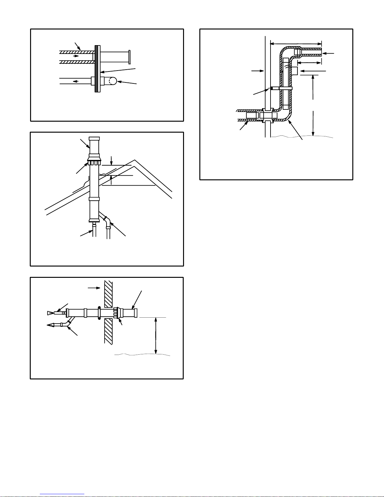
8 - If intake and exhaust piping must be run up a side
wall to position above snow accumulation or other
obstructions, the piping must be supported every 3
fee t (.91 m) as shown in figure 14. Refer to figures 13
and 15 for proper piping method. WTK wall terminaĆ
tion kit must be extended for use in this application.
See figure 18 or use kit WTKX shown in figure 19.
When exhaust and intake piping must be run up an
outside wall, the exhaust piping is reduced to 1 1/2
inches (38 mm) after the final elbow. The intake pipĆ
ing may be equ i p ped wit h a 90° elbow turndown. UsĆ
in g tu rn- do wn wi ll ad d 5 fe et (1 . 5 m) to th e eq ui va len t
length of the pipe.
Page 11
Page 12
1/2 (12.7) FOAM INSULATION
IN UNCONDITIONED SPACE
Inches (mm)
OUTSIDE WALL
Inches(mm)
UNCONDITIONED
SPACE
OUTSIDE WALL
12 (305) MIN. for 2 (51)
20 (508) MAX. for 3 (76)
8 (203)
MIN.
EXHAUST
INTAKE
PIPE
PIPE
Optional Turndown
TOP VIEW
WALL TERMINATION
(22G44) LB-49107CD for 2 (50.8) Venting
(44J40) LB-65701A for 3 (76.2) Venting
(Intake Only)
FIGURE 10
EXHAUST
TERMINATION
INTAKE
TERMINATION
EXHAUST
CONCENTRIC ROOFTOP TERMINATION
(60G77) LB-49107CE for G32V-75 Units Only
(33K97) LB-87942 for G32V-100 & -125 Units Only
12 (305) ABOVE
AVERAGE SNOW
ACCUMULATION
INTAKE
Inches (mm)
FIGURE 11
OUTSIDE WALL
EXHAUST
INTAKE
Inches (mm)
CONCENTRIC WALL TERMINATION
(60G77) LB-49107CE for G32V-75 Units Only
(33K97) LB-87942 for G32V-100 & -125 Units Only
EXHAUST
TERMINATION
INTAKE
TERMINATION
12 (305) Min.
above grade.
Shown
PROVIDE SUPPORT
FOR INTAKE AND
EXHAUST LINES EVERY
36 (914)
1/2 (13) FOAM
INSULATION IN
UNCONDITIONED
SPACE
WALL RING TERMINATION
(15F74) LB-49107CB for 2 in. (51) Venting
See venting table 5 for maximum venting lengths with
SIDE VIEW
this arrangement.
12 (305) ABOVE
AVERAGE SNOW
ACCUMULATION
1/2 (13) FOAM
INSULATION
FIGURE 13
9 - Position termination ends so they are free from any
obstructions and above the level of snow accumulaĆ
tion (where applicable). Termination ends must be a
minimum of 12 inches (305 mm) above grade level.
Do not point into window wells, stairwells, alcoves,
courtyard areas or other recessed areas. Do not
position termination ends directly below roof eaves
or above a walkway. Since the G32V is a certified diĆ
rect vent, Category IV gas furnace, the location of
the termination is limited by local building codes. In
the absence of local codes, refer to the current NaĆ
tional Fuel Gas Code ANSI Z223-1 in USA, and curĆ
rent standard CAN/CGA-B149.1 of the Natural Gas
Installation Instructions in Canada for details. The
termination should be at least 12 inches (305 mm)
from any opening through which flue products could
enter the building.
When horizontally vented, minimum clearance for
termination from electric meters, gas meters, regulaĆ
tors and relief equipment is 4 feet (1.2 m) for US
installations. Refer to the current CAN/CGA-B149.1
for installations in Canada or with authorities having
local jurisdiction.
FIGURE 12
Page 12
Page 13
At vent termination, care must be taken to maintain
protective coatings over building materials (proĆ
longed exposure to exhaust condensate can destroy
protective coatings). It is recommended that the exĆ
haust outlet not be located within 6 feet (1.8 m) of a
condensing unit because the condensate can damĆ
age the painted coating.
METAL OR PLASTIC
STRAPPING
OR LARGE
WIRE TIES
FIGURE 14
IMPORTANT
Combustion air intake inlet and exhaust outlet
should not be located within 6 feet (1.8 m) of dryer
vent or combustion air inlet or outlet of another apĆ
pliance. Piping should not exit less than 3 feet (.91 m)
from opening into another building.
IMPORTANT
For Canadian Installations Only:
In accordance to CAN/CGA-B149.1 and .2, the miniĆ
mum allowed distance between the combustion air
intake inlet and the exhaust outlet of other apĆ
pliances shall not be less than 12 inches (305 mm).
10 - Suspend piping using hangers at a minimum of every
5 feet (1.52 m) for schedule 40 PVC and every 3 feet
(.91 m) for ABS-DWV, PVC-DWV, SDR-21 PVC,
and SDRĆ26 PVC piping. A suitable hanger can be
fabricated by using metal or plastic strapping or a
large wire tie.
11 - In areas where piping penetrates joists or interior
walls, hole must be large enough to allow clearance
on all sides of pipe as it passes through the center of
the hole.
12 - Isolate piping at the point where it exits the outside
wall or roof.
13 - When furnace is installed in a residence where unit is
shut down for an extended period of time, such as a
vacation home, make provisions for draining conĆ
densate collection trap and lines.
14 - Based on the recommendation of the manufacturer,
a multiple furnace installation may use a group of up
to four termination kits WTK assembled together
horizontally, as shown in figure 17.
Inches(mm)
3 (76) OR
2 (51) 90_ ELBOW
Optional Turndown
(Not Shown)
May Be Used on
Intake Only
(22G44) LB-49107CD for 2(51) Venting
(44J40) LB-65701A for 3(76) Venting
Front View
INTAKE
VENT
1/2 (13) Foam
Insulation in
Unconditioned Space
Inches (mm)
WALL TERMINATION KIT (30G28) WTK
1/2 (13)
FOAM
INSULATION
FRONT VIEW
WALL TERMINATION
FIGURE 15
12
(305)
VENT TERMINATIONS
FIGURE 16
3 x 2 (76 x 51) OR
2 x 1-1/2 (51 x 38)
REDUCER BUSHING LOCAĆ
FOR OFFSET TERMINATION
TION
3 (76) OR
2 (51) 90_ ELBOW
EXHAUST VENT
5
(127)
Side View
EXHAUST VENT
INTAKE VENT
OUTSIDE WALL
Page 13
Page 14

Front View
INTAKE VENT
EXHAUST
VENT
18 MAX.
(457)
5
(127)
5-1/2
(140)
12
(305)
Inches (mm)
Front View
34
(864)
9
(229)
INTAKE
VENT
EXHAUST
VENT
NOTE - Enclosed exhaust pipe is
insulated with 1/2 inch (13 mm)
foam insulation. If intake and exĆ
haust pipes are reversed, slit and
remove foam insulation and
reapply to other vent. Exhaust
vent must be insulated.
Side View
EXHAUST VENT
Inches (mm)
OPTIONAL VENT TERMINATION FOR
MULTIPLE UNIT INSTALLATION
WALL TERMINATION KIT WTK
FIGURE 17
AIR
12
(305)
5Ć1/2
(140)
Minimum
8 (203)
Front View
INTAKE
AIR
5
(127)
EXHAUST
INTAKE
AIR
MODEL WTK WALL TERMINATION KIT (30G28)
EXTENDED VENT FOR GRADE CLEARANCE
VENT TERMINATIONS
FIGURE 18
INTAKE
VENT
COVER EXHAUST
VENT WITH
1/2 (13)
FOAM
INSULATION
EXHAUST
AIR
12 MIN.
(305)
Above Grade
GRADE
Side View
Inches (mm)
12 (305)
Minimum
ABOVE GRADE
GRADE
Side View
4
(102)
12
(305)
GRADE
EXHAUST VENT
8 MIN.
(203)
INTAKE
VENT
OUTSIDE WALL
GRADE
VENT TERMINATIONS
MODEL WTKX (30G79)
EXTENSION RISER FOR GRADE CLEARANCE
FIGURE 19
G32 VENTING IN EXISTING CHIMNEY
3 in. - 8 in.
8 in. - 12 in.
(203 mm - 305 mm)
INTAKE VENT
INSULATION
(OPTIONAL)
TOP PLATE
(18 GA. MIN.)
MIN. 12" (304 mm)
ABOVE ROOF
INSULATE
TO FORM
SEAL
NOTE - Do not discharge exhaust gases directly into any chimney or vent stack.
If vertical discharge through an existing unused chimney or stack is required,
insert piping inside chimney until the pipe open end is above top of chimney and
terminate as illustrated. In any exterior portion of chimney, the exhaust vent
must be insulated.
(76 mm203 mm)
STRAIGHT CUT OR
ANGLE CUT IN DIRECTION
OF ROOF SLOPE
EXHAUST VENT
1/2" (13 mm)
WEATHERPROOF
INSULATION
SHOULDERS OF FITTINGS
PROVIDE SUPPORT FOR
PIPE ON TOP PLATE
ALTERNATE
3 in. - 8 in.
(76 mm203 mm)
INTAKE VENT
EXTERIOR
PORTION
OF CHIMNEY
FIGURE 20
Page 14
Page 15

Condensate Piping
This unit is designed for either right- or left-side exit of
condensate piping. Route the condensate drainline only
within the conditioned space: this prevents possible
freezing of the condensate, which would block the drainline. Use an electric heat cable if you route the condensate line through unconditioned areas.
CAUTION
Do not use copper tubing or existing copper conĆ
densate lines for drain line.
1 - Determine which side of the unit that the condensate
will exit.
2 - Connect 1/2" (13 mm) plastic pipe plug (provided) in
the unused end of the condensate trap. Install plug
so that it is sealed water tight yet able to be removed.
Do not permanently seal the connection. Teflon tape
is recommended to seal joint. See figure 21.
CONDENSATE ASSEMBLY
(For left or right installation)
COLD
COMBUSTION AIR
BLOWER BRACKET
HEADER
BOX
Right-Hand Side Condensate Exit:
Install the nipple/adapter assembly from the outĆ
side of the cabinet and insert the adapter into the
threaded opening in the condensate trap.
Left-Hand Side Condensate Exit:
Insert nipple/adapter assembly from the left-hand
side of the cabinet and through the combustion air
blower mounting structure into the threaded
opening in the condensate trap.
5 - Connect field-supplied plumbing to nipple and route
to open drain. Plumbing should be vented to a point
higher than the condensing coil. See figure 22.
CONDENSATE PLUMBING
(Plumbing must be vented higher than coil.)
NIPPLE
ADAPTER
ELBOW
CONDENSATE TRAP
NIPPLE
ADAPTER
PLUG
BOOT OR CAP
FIGURE 21
3 - Use the provided adapter (1/2" mpt X 3/4" PVC) and
a field-provided nipple to carry drainage outside the
cabinet. A 1/2" CPVC x 1/2" MPT adapter and 1/2"
CPVC is acceptable for use.
4 - Glue nipple to the adapter using the procedures out-
lined in the Joint Cementing Procedures" section.
The nipple/adapter assembly should be connected
in a non-permanent manner and must be water tight.
Teflon tape is recommended to seal the joint.
FIGURE 22
6 - Connect condensate drain line [1/2" (13 mm) SDR 11
plastic pipe or tubing] to condensate connection on
condensate trap assembly and route to open drain.
Condensate line must be sloped downward away
from condensate trap to the drain. If drain level is
above condensate outlet, use a condensate pump to
pump condensate to the higher level. Condensate
drain line should be routed within the conditioned
space to avoid freezing of condensate and blockage
of drain line. If this is not possible, a heat cable kit
may be used on the condensate trap and condenĆ
sate line. Heating cable kit is available from Lennox
in various lengths; 6 feet (1.8 m) - kit no. 26K68; 24
feet (7.3 m) - kit no. 26K99; and 50 feet (15.2 m) - kit
no. 26K70. Also available from Lennox: 1/2" (12.7
mm) glass fiber tape - 39G04; 2" (50.8 mm) plum foil
tape - 39G03.
Page 15
Page 16

Gas Piping
CAUTION
If a flexible gas connector is required or allowed by
the authority that has jurisdiction, black iron pipe
shall be installed at the gas valve and extend outĆ
side the furnace cabinet.
1 - Gas piping may be routed into the unit through either
the left- or right-hand side. Supply piping enters into
the gas valve from the bottom of the valve as shown
in figure 23.
2 - When connecting the gas supply, factors such as
length of run, number of fittings and furnace rating
must be considered to avoid excessive pressure
drop. Table 6 lists recommended pipe sizes for typiĆ
cal applications.
NOTE - Use two wrenches when connecting gas pipĆ
ing to avoid transferring torque to the manifold.
3 - The gas piping must not run in or through air ducts,
clothes chutes, gas vents or chimneys, dumb waitĆ
ers, or elevator shafts. Center gas line through piping
hole. Gas line should not touch side of unit. When
left-hand gas plumbing is required, gas line should
be installed in the lower half of knockout so that piping will clear combustion air blower. See figure 23.
LEFT SIDE PIPING
4 – The piping should be sloped 1/4 inch (6.4 mm) per 15
feet (4.57 m) upward toward the meter from the furĆ
nace. The piping must be supported at proper interĆ
vals [every 8 to 10 feet (2.44 to 3.01 m)] using suitĆ
able hangers or straps. A drip leg should be installed
in vertical pipe runs to the unit.
5 - In some localities, codes may require installation of a
manual main shutĆoff valve and union (furnished by
the installer) external to the unit. Union must be of the
ground joint type.
NOTE - Install a 1/8 inch NPT plugged tap in the field pipĆ
ing upstream of the gas supply connection to the unit. The
tap must be accessible for test gauge connection. See
figure 24.
MANUAL MAIN SHUT-OFF
VALVE WILL NOT HOLD
NORMAL TEST PRESSURE
1/8 in. (3.2 mm) NPT
PLUGGED TAP
CAP
FURNACE
ISOLATE
GAS VALVE
FIGURE 24
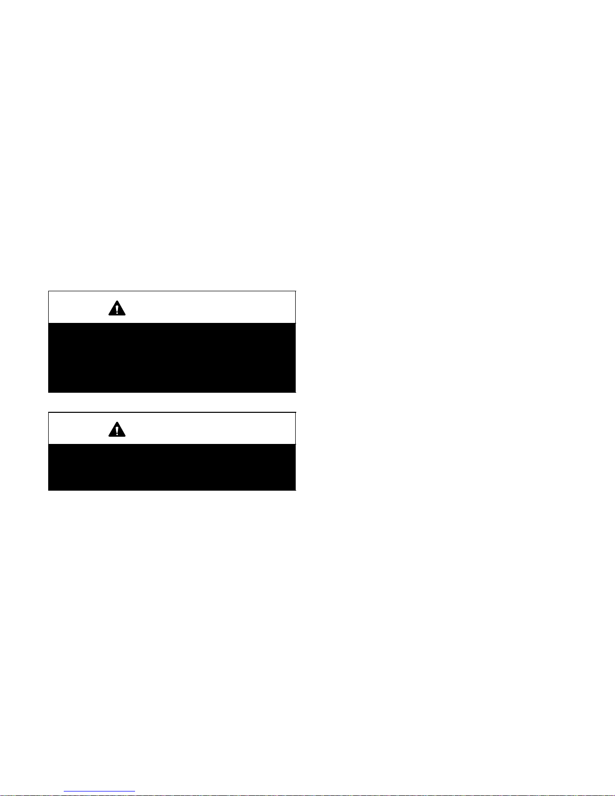
Leak Check
After gas piping is completed, carefully check all piping
connections (factory- and field-installed) for gas leaks.
Use a leak detecting solution or other preferred means.
MANUAL MAIN
SHUT-OFF
VALV E
1/8 in. NPT
PLUGGED
TAP
GAS VALVE
GAS VALVE
RIGHT SIDE PIPING
(STANDARD)
FIGURE 23
MANUAL MAIN
SHUT-OFF
VALV E
1/8 in. NPT
PLUGGED
TAP
IMPORTANT
Some soaps used for leak detection are corrosive
to certain metals. Carefully rinse piping thoroughly
after leak test has been completed. Do not use
matches, candles, flame, or other sources of igniĆ
tion to check for gas leaks.
IMPORTANT
The furnace must be isolated from the gas supply
piping system by closing its individual manual
shut-off valve during any pressure testing of the
gas supply piping system at test pressures equal
to or less than 1/2 psig (3.45 kPa). See figure 24.
The furnace and its individual shut-off valve must
be disconnected from the gas supply piping sysĆ
tem during any pressure testing of the system at
test pressures greater than 1/2 psig (3.45 kPa).
Page 16
Page 17

Nominal Internal
Nominal
Internal
Iron Pipe Size
-Inches(mm)
1/4
(6.35)
3/8
(9.53)
1/2
(12.7)
3/4
(19.05)
1
(25.4)
1-1/4
(31.75)
1-1/2
(38.1)
2
(50.8)
2-1/2
(63.5)
3
(76.2)
4
(101.6)
Diameter
-Inches(mm)
.364
(9.246)
.493
(12.522)
.622
(17.799)
.824
(20.930)
1.049
(26.645)
1.380
(35.052)
1.610
(40.894)
2.067
(52.502)
2.469
(67.713)
3.068
(77.927)
4.026
(102.260)
NOTE - Capacity given in cubic feet (m
GAS PIPE CAPACITY - ft.3/hr (m3/hr)
TABLE 6
Length of Pipe-Feet (m)
10
(3.048)20(6.096)30(9.144)40(12.192)50(15.240)60(18.288)70(21.336)80(24.384)90(27.432)
43
(1.13)
95
(2.69)
175
(4.96)
360
(10.19)
680
(19.25)
1400
(39.64)
2100
(59.46)
3950
(111.85)
6300
(178.39)
11000
(311.48)
23000
(651.27)
3
) of gas per hour and based on 0.60 specific gravity gas.
29
(.82)
65
(1.84)
120
(3.40)
250
(7.08)
465
(13.17)
950
(26.90)
460
(41.34)
2750
(77.87)
4350
(123.17)
7700
(218.03)
15800
(447.39)
24
(.68)
52
(1.47)
97
(2.75)
200
(5.66)
375
(10.62)
770
(21.80)
1180
(33.41)
2200
(62.30)
3520
(99.67)
6250
(176.98)
12800
(362.44)
20
(.57)
45
(1.27)
82
(2.32)
170
(4.81)
320
(9.06)
660
(18.69)
990
(28.03)
1900
(53.80)
3000
(84.95)
5300
(150.07)
10900
(308.64)
18
(.51)
40
(1.13)36(1.02)
73
(2.07)66(1.87)
151
(4.28)
285
(8.07)
580
(16.42)
900
(25.48)
1680
(47.57)
2650
(75.04)
4750
(134.50)
9700
(274.67)
(3.91)
(7.36)
(15.01)
(22.94)
(43.04)
(67.96)
(121.76)
(249.18)
16
(.45)
138
260
530
810
1520
2400
4300
8800
15
(.42)
33
(.73)
61
(1.73)
125
(3.54)
240
(6.80)
490
(13.87)
750
(21.24)
1400
(39.64)
2250
(63.71)
3900
(110.43)
8100
(229.36)
14
(.40)
31
(.88)
57
(1.61)
118
(3.34)
220
(6.23)
460
(13.03)
690
(19.54)
1300
(36.81)
2050
(58.05)
3700
(104.77)
7500
(212.37)
13
(.37)
29
(.82)
53
(1.50)
110
(3.11)
205
(5.80)
430
(12.18)
650
(18.41)
1220
(34.55)
1950
(55.22)
3450
(97.69)
7200
(203.88)
100
(30.480)
12
(.34)
27
(.76)
50
(1.42)
103
(2.92)
195
(5.52)
400
(11.33)
620
(17.56)
1150
(32.56)
1850
(52.38)
3250
(92.03)
6700
(189.72)
Electrical
A field make-up box is provided for line voltage wiring.
Line voltage wiring to unit is done through the J69 jack
from the field make-up box to plug P69 from the control
box. See figures 25 and 26 for make-up box installation.
Refer to figure 27 for schematic wiring diagram and trouĆ
bleshooting, figure 28 for point-to-point field wiring and
figure 29 for a detailed illustration of the Surelight inteĆ
grated control.
ELECTROSTATIC DISCHARGE (ESD)
Precautions and Procedures
CAUTION
Electrostatic discharge can affect electronic comĆ
ponents. Take precautions during furnace installaĆ
tion and service to protect the furnace's electronic
controls. Precautions will help to avoid control exĆ
posure to electrostatic discharge by putting the
furnace, the control and the technician at the same
electrostatic potential. Neutralize electrostatic
charge by touching hand and all tools on an unĆ
painted unit surface, such as the gas valve or blowĆ
er deck, before performing any service procedure.
1 - Select circuit protection and wire size according to
the unit nameplate. The power supply wiring must
meet Class 1 restrictions.
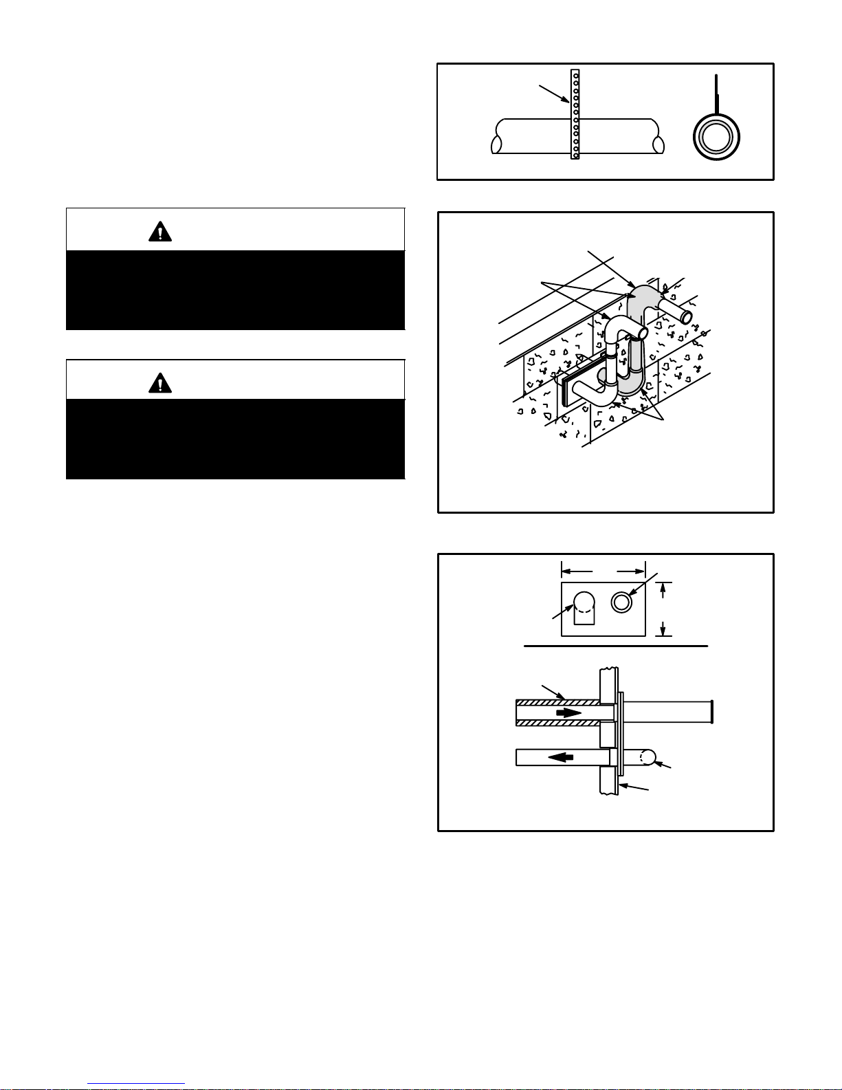
2 - A snaphole bushing is provided to seal around the
wiring as it enters the cabinet. A snaphole plug is proĆ
vided to seal the unused wire entry hole.
3 - Install a separate disconnect switch (protected by eiĆ
ther a fuse or circuit breaker) near the unit so that
power can be turned off for servicing.
4 - Install field makeĆup box on either side, inside or out
of the cabinet. Knockouts are provided in box and
cabinet to facilitate wiring. See figures 25 and 26.
To ensure proper grounding of the furnace, two lockĆ
washers are included in the electrical make-up box
bag assembly. Place each lockwasher on a securing
screw before installing the make-up box. Make sure
the lockwasher breaks the paint on the cabinet so
that the washer is touching metal. Unit is not properly
grounded if paint has not been removed by the lockĆ
washer.
5 - Remove cap from knockout in blower deck on the
same side as the installed make-up box.
6 - Insert the three-pin (P69) plug from the control box
into the knockout provided in the blower deck.
7 - Connect jack (J69) from make-up box to jack plug in
blower deck.
8 - Before connecting the thermostat or the power wirĆ
ing, check to make sure the wires will be long enough
for servicing at a later date. Remove the blower acĆ
cess panel to check the length of the wire.
9 - Electrically ground unit in accordance with local
codes or, in the absence of local codes, according to
the current National Electric Code (ANSI/NFPA No.
70) and in Canada with the current Canadian Electric
Code part 1 (CSA standard C22.1). The ground wire
is provided in the field make-up box.
Page 17
Page 18

IMPORTANT
Ignition control will not operate unless unit is propĆ
erly grounded. 120V supply must be installed with
correct polarity.
CAUTION
Bundle all wires connected to control board in
such a way that drip loops are formed. Drip loops
direct damaging moisture away from control
board.
INTERIOR MAKE-UP BOX INSTALLATION
MAKE-UP
BOX
J69
BUSHING
FIGURE 25
EXTERIOR MAKEĆUP BOX INSTALLATION
MAKE-UP
BOX
J69
P69 from
Control Box
BUSHING
10 -One line voltage EAC" terminal is provided on the
furnace control board. Any electronic air cleaner
rated up to one amp can be connected to this termiĆ
nal with the neutral leg of the circuit being connected
to the neutral EAC" terminal. See figure 29 for conĆ
trol board configuration. This terminal is energized
when the indoor blower is operating.
11 -One line voltage HUM" terminal is provided on the
furnace control board. Any humidifier rated up to one
amp can be connected to this terminal with the neuĆ
tral leg of the circuit being connected to the neutral
HUM" terminal. See figure 29 for control board conĆ
figuration. This terminal is energized in the heating
mode whenever the combustion air inducer is operĆ
ating.
12 - Install room thermostat according to instructions
provided with thermostat. The furnace may be conĆ
trolled by either a single- or two-stage thermostat. If
furnace is being used with heat pump refer to FM21
installation instruction.
13 - Complete wiring connections to equipment using
wiring diagrams provided with unit and figures 27
and 28. Use 18-gauge wire or larger that is suitable
for Class II rating for thermostat connections. See
table 7 for diagrams for specific applications.
Indoor Blower Speeds
1 - When the thermostat is set to FAN ON," the indoor
blower will run continuously at approximately 38% of
the second-stage cooling speed when there is no
cooling or heating demand.
2 - When the G32V unit is running in the heating mode,
the indoor blower will run on the heating speed desigĆ
nated by the positions of dip switches 11 and 12.
3 - When there is a cooling demand, the indoor blower
will run on the cooling speed designated by the posiĆ
tions of dip switches 5 and 6.
P69 from
Control Box
FIGURE 26
Page 18
Page 19

TYPICAL G32V SCHEMATIC WIRING DIAGRAM
FIGURE 27
Page 19
Page 20

TYPICAL G32V FIELD WIRING DIAGRAM
FIGURE 28
Thermostat
1 Heat / 1 Cool
NOTE - Use dip
switch 3 to set
second-stage
heat ON delay.
ON-10 minutes.
OFF-15 minĆ
utes.
1 Heat / 1 Cool
with CCB1
NOTE - Use dip
switch 3 to set
second-stage
heat ON delay.
ON-10 minutes.
OFF-15 minĆ
utes.
TABLE 7
Field Wiring Applications
Jumper Settings (See figure 29)
E20
Term. Strip
Y1 to Y2
W914 W951
SINGLE Yes Intact Intact
SINGLE Yes Cut Intact
Wiring Connections
S1
T'STAT
S1
T'STAT
CONTROL
TERM. STRIP
CCB1
CONTROL
TERM. STRIP
OUTDOOR
UNIT
OUTDOOR
UNIT
Page 20
Page 21

Thermostat
1 Heat / 2 Cool
NOTE - Use dip
switch 3 to set
second-stage
heat ON delay.
ON-10 minutes.
OFF-15 minĆ
utes.
TABLE 7
Field Wiring Applications (Continued)
Jumper Settings (See figure 29)
E20
Term. Strip
Y1 to Y2
W914 W951
SINGLE No Intact Intact
Wiring Connections
S1
T'STAT
CONTROL
TERM. STRIP
OUTDOOR
UNIT
1 Heat / 2 Cool
SINGLE No Cut Intact
with CCB1
NOTE - Use dip
switch 3 to set
second-stage
heat ON delay.
ON-10 minutes.
OFF-15 minĆ
utes.
2 Heat / 2 Cool TWO No Intact Intact
S1
T'STAT
S1
T'STAT
CCB1
CONTROL
TERM. STRIP
CONTROL
TERM. STRIP
OUTDOOR
UNIT
OUTDOOR
UNIT
2 Heat / 2 Cool
TWO No Cut Intact
with CCB1
Page 21
S1
T'STAT
CCB1
CONTROL
TERM. STRIP
OUTDOOR
UNIT
Page 22

TABLE 7
Field Wiring Applications (Continued)
Jumper Settings (See figure 29)
Thermostat
E20
Term. Strip
Y1 to Y2
W914 W951
2 Heat / 1 Cool TWO Yes Intact Intact
Wiring Connections
S1
T'STAT
CONTROL
TERM. STRIP
OUTDOOR
UNIT
FM21 Heat
Pump / 1 Cool
Harmony
Application*
2 Heat / 1 Cool
SINGLE Yes Intact Cut
TWO Yes Cut Intact
*Disconnect existing
furnace transformer
and replace with 75VA,
24V transformer if deĆ
frost option to be used.
75VA, 24V
TRANSFORMER*
NOTE - Wiring connecĆ
tions to outdoor unit and
thermostat made at
FM21 control board per
FM21 instructions.
TEMP.
MOD.
SWITCH
FAN LO
FAN LINE
HARMONY
CONTROL
TERM. STRIP
CONTROL
TERM.
STRIP
FM21
NOTE Remove
Y1/Y2 jumper
for two-stage
cooling.
OUTĆ
DOOR
UNIT
Harmony
TWO No Cut Intact
Application*
2 Heat / 2 Cool
*Cut wires at pin positions 2 and 13 of J/P46. Insulate ends to prevent a short. Blower operates on PWM signal generated by Harmony. Harmony
overrides blower speed taps. Blower speed varies according to zone demand. Low and high-fire controlled by temperature modulating switch.
Page 22
TEMP.
MOD.
SWITCH
FAN LO
FAN LINE
HARMONY
CONTROL
TERM.
STRIP
OUTĆ
DOOR
UNIT
Page 23

Integrated Control Board Settings
TWO-STAGE, VARIABLE SPEED INTEGRATED CONTROL BOARD
DIAGNOSTIC
LEDs
DIP
SWITCHES
1 - 3
E20
THERMOSTAT
SELECTION
JUMPER
1/4" QUICK CONNECT TERMINALS
THERMOSTAT CONNECTIONS (TB1)
LEDs
ON-BOARD
JUMPER W914
(cut when CCB1 or
Harmony II are used)
FACTORY-
INSTALLED
JUMPER
ON-BOARD
JUMPER W951
(cut when heat pump is
used with FM21)
DIP
SWITCHES
5 - 12
LED
FIGURE 29
G32V units are equipped with a two-stage, variable
speed SureLight integrated control. This control manĆ
ages ignition timing, heating mode fan off delays and inĆ
door blower speeds based on selections made using the
control dip switches and jumpers. The control includes an
internal watchguard feature which automatically resets
the ignition control when it has been locked out because
the burner has failed to light. After one hour of continuous
thermostat demand for heat, the watchguard will break
and remake thermostat demand to the furnace and autoĆ
matically reset the control to relight the furnace.
Thermostat Selection Jumper (E20)
This unit may be used with either a single-stage or twostage thermostat. The thermostat selection jumper, loĆ
cated just below dip switches 1 through 3, must be propĆ
erly positioned for the particular application. The jumper
is factory positioned for use with a two-stage thermostat.
If a single-stage thermostat is to be used, the jumper must
be repositioned.
DIP SWITCH FUNCTIONS
DIP SWITCH(ES) FUNCTION
1 and 2 Blower Off Delay
3 Second Stage ON Delay (Single-stage t'stat)
4 Not used
5 and 6 Cooling Mode Blower Speed
7 and 8 Blower Speed Adjustment
9 and 10 Cooling Mode Blower Ramping Profile
11 and 12 Heating Mode Blower Speed
a - Select TWO" for two-stage heating operation conĆ
trolled by a two-stage heating thermostat (factory
setting);
b - Select SINGLE" for two-stage heating operation
controlled by a single-stage heating thermostat.
This setting provides a timed delay before secondstage heat is initiated.
Dip Switch Settings
Switches 1 and 2 -- Blower Off Delay -- The blower-on
delay of 45 seconds is not adjustable. The blower-off deĆ
lay (time that the blower operates after the heating deĆ
mand has been satisfied) can be adjusted by moving
switches 1 and 2 on the integrated control board. The unit
is shipped from the factory with a blower-off delay of 90
seconds. The blower off delay affects comfort and is adĆ
justable to satisfy individual applications. Adjust the blowĆ
er off delay to achieve a supply air temperature between
90° and 110°F at the exact moment that the blower is de-
Page 23
Page 24

energized. Longer off delay settings provide lower supply
air temperatures; shorter settings provide higher supply
air temperatures.The table below provides the blower off
timings that will result from different switch settings.
TABLE 8
Blower Off Delay Switch Settings
Blower Off Delay
(Seconds)
Switch 1 Switch 2
60 Off Off
90 Off On
120 On Off
180 On On
Switch 3 -- Second Stage Delay (Used with SingleStage Thermostat Only) -- This switch is used to deterĆ
mine the second stage on delay when a single-stage therĆ
mostat is being used. The switch is factory-set in the ON
position, which provides a 10-minute delay before secĆ
ond-stage heat is initiated. If the switch is toggled to the
OFF position, it will provide a 15-minute delay before secĆ
ond-stage heat is initiated. This switch is only activated
when the thermostat selector jumper is positioned for
SINGLE-stage thermostat use.
Switch 4 -- Not used in G32V application.
Switches 5 and 6 -- Cooling Mode Blower Speed --
Switches 5 and 6 are used to select cooling blower motor
speed. The unit is shipped from the factory with the dip
switches positioned for high speed (4) indoor blower moĆ
tor operation during the cooling mode. The table below
provides the cooling mode blower speeds that will result
from different switch settings. Refer to tables 13 through
13 for corresponding cfm values.
TABLE 9
Cooling Mode Blower Speeds
Speed Switch 5 Switch 6
1 - Low On On
2 - Medium Low Off On
3 - Medium High On Off
4 - High (Factory) Off Off
Switches 7 and 8 -- Blower Speed Adjustment --
Switches 7 and 8 are used to select blower speed adjustĆ
ment settings. The unit is shipped from the factory with
the dip switches positioned for NORMAL (no) adjustĆ
ment. The dip switches may be positioned to adjust the
blower speed by -15% to better suit the application. The
table below provides blower speed adjustments that will
result from different switch settings. Refer to tables 13
and14 for corresponding cfm values.
TABLE 10
Blower Speed Adjustment
Adjustment Switch 7 Switch 8
NORMAL (Factory) Off Off
-15% (approx.) Off On
Switches 9 and 10 -- Cooling Mode Blower Speed
Ramping -- Switches 9 and 10 are used to select cooling
mode blower speed ramping options. Blower speed
ramping may be used to enhance dehumidification perĆ
formance. The switches are factory set at option A which
has the greatest effect on blower motor performance. The
table below provides the cooling mode blower speed
ramping options that will result from different switch setĆ
tings. The cooling mode blower speed ramping options
are detailed below.
TABLE 11
Cooling Mode Blower Speed Ramping
Ramping Option Switch 9 Switch 10
A (Factory) Off Off
B On Off
C Off On
D On On
Ramping Option A (Factory Selection)
Motor runs at 50% for 1/2 minute.
Motor then runs at 82% for approximately 7-1/2 miĆ
nutes.
If demand has not been satisfied after 7-1/2 minutes,
motor runs at 100% until demand is satisfied.
Once demand is met, motor runs at 50% for 1/2 minĆ
ute.
Motor ramps down to off.
OFF
1/2 MIN
50% CFM
7-1/2 MIN
82% CFM
COOLING DEMAND
100%
CFM
1/2 MIN
50% CFM
OFF
Ramping Option B
Motor runs at 50% for 1/2 minute.
Motor then runs at 82% for approximately 7-1/2 miĆ
nutes.
If demand has not been satisfied after 7-1/2 minutes,
motor runs at 100% until demand is satisfied.
Once demand is met, motor ramps down to off.
OFF
1/2 MIN
50% CFM
7-1/2 MIN
82% CFM
COOLING DEMAND
100% CFM
OFF
Ramping Option C
Motor runs at 82% for approximately 7-1/2 minutes.
If demand has not been satisfied after 7-1/2 minutes,
the motor runs at 100% until demand is satisfied.
Once demand is met, motor ramps down to off.
OFF
7-1/2 MIN
82%CFM
COOLING DEMAND
100% CFM
OFF
Ramping Option D
Motor runs at 100% until demand is satisfied.
Once demand is met, motor ramps down to off.
Page 24
Page 25

100% CFM
COOLING
DEMAND
OFFOFF
Switches 11 and 12 -- Heating Mode Blower Speed --
Switches 11 and 12 are used to select heating mode blowĆ
er motor speed. The unit is shipped from the factory with
the dip switches positioned for medium low (2) speed inĆ
door blower motor operation during the heating mode.
The table below provides the heating mode blower
speeds that will result from different switch settings. Refer
to tables 13 and 14 for corresponding cfm values.
TABLE 12
Heating Mode Blower Speeds
Speed Switch 11 Switch 12
1 - Low On On
2 - Medium Low
(Factory)
Off On
3 - Medium High On Off
4 - High Off Off
On-Board Jumper W914
On-board jumper W914, which connects terminals DS
and R on the integrated control board, must be cut when
the furnace is installed with either the Harmony II zone
control board or the CCB1 EfficiencyPlus humidity conĆ
trol. Refer to table 15 for operation sequence in applicaĆ
tions including a G32V, CCB1 and single-speed outdoor
unit. Table 16 gives the operation sequence in applicaĆ
tions with a two-speed outdoor unit.
On-Board Jumper W951
On-board jumper W951, which connects terminals R and
O on the integrated control board, must be cut when the
furnace is installed in applications which include a heat
pump unit and the FM21 FuelMaster control board.
Factory-Installed Jumper Y1 to Y2
A factory-installed jumper from Y1 to Y2 terminals on the
integrated control board terminal strip must be removed if
two-stage cooling will be used.
Diagnostic LEDs (DS1 and DS2)
Two diagnostic LEDs are located on the two-stage, variĆ
able speed integrated control just to the left of the first
bank of dip switches. The LED flashes correspond with
diagnostic codes detailed on page 35.
Status LEDs (HEAT, HI/LO, ON/OFF and CFM)
The integrated control includes four LEDs which indicate
operating status. The green ON/OFF LED is lit any time
the blower is operating. The green CFM LED indicates
the blower motor speed. Count the number of blinks beĆ
tween the two-second pauses to determine the CFM.
Each blink represents approximately 100 CFM. The yelĆ
low HI/LO LED is lit when the W914 (DS to R) jumper has
not been clipped for CCB1 or Harmony operation. The
yellow HEAT LED is lit when the indoor blower is operatĆ
ing at the HEATING speed.
Page 25
Page 26

TABLE 13
G32V3-75 BLOWER MOTOR PERFORMANCE
0.0" to 0.8" w.g. (0 through 200 Pa) External Static Pressure Range
Blower Speed Adjustment Settings (Switches 5 and 6)
Cool
Adjust"
Setting
1 2 3 4 1 2 3 4
cfm L/s cfm L/s cfm L/s cfm L/s cfm L/s cfm L/s cfm L/s cfm L/s
Norm 880 415 930 440 980 465 1040 490 1060 500 1105 520 1260 595 1330 630
ć
775 365 810 380 850 400 910 430 930 440 970 460 1070 505 1130 535
Low Speed High Speed
Blower Speed Adjustment Settings (Switches 7 and 8)
Heat
Adjust"
Setting
1 2 3 4 1 2 3 4
cfm L/s cfm L/s cfm L/s cfm L/s cfm L/s cfm L/s cfm L/s cfm L/s
Norm 945 446 1025 484 1125 531 1270 599 1080 510 1172 533 1286 607 1452 685
ć
803 379 871 411 956 451 1080 510 918 433 996 470 1093 516 1234 582
15% lower motor speed than NORM switch setting.
NOTE - The effect of static pressure and filter resistance is included in air volumes shown.
NOTE - Continuous Fan only speed is approximately 800 cfm (380 L/s) - non adjustable.
NOTE - Lennox Harmony IIt zone control applications - MAX CFM is determined by COOL switch setting with a minimum of approximately 850
cfm (400 L/s) for all positions.
Low Speed High Speed
TABLE 14
G32V5-100/125 BLOWER MOTOR PERFORMANCE
0.0" to 0.8" w.g. (0 through 200 Pa) External Static Pressure Range
Blower Speed Adjustment Settings (Switches 5 and 6)
Cool
Adjust"
Setting
1
cfm L/s cfm L/s cfm L/s cfm L/s cfm L/s cfm L/s cfm L/s cfm L/s
Low Speed High Speed
2
3 4 1
2
3 4
Norm 1140 540 1250 590 1440 680 1550 730 1620 765 1820 860 2000 945 2100 990
ć
970 455 1060 500 1280 605 1320 595 1380 650 1550 730 1700 800 1780 840
Blower Speed Adjustment Settings (Switches 7 and 8)
Heat
Adjust"
Setting
1 2 3 4 1 2 3 4
cfm L/s cfm L/s cfm L/s cfm L/s cfm L/s cfm L/s cfm L/s cfm L/s
Norm 1140 540 1250 590 1440 680 1550 730 1560 735 1720 810 2030 960 2150 1015
ć
15% lower motor speed than NORM switch setting.
G32V5-125 Models Only - Do not set switches for position #1 (at NORM or ć" setting) or position #2 (at -" setting) for HEAT speed.
NOTE - The effect of static pressure and filter resistance is included in air volumes shown.
NOTE - Continuous Fan only speed is approximately 1150 cfm (545 L/s) - non adjustable.
NOTE - Lennox Harmony IIt zone control applications - MAX CFM is determined by COOL switch setting with a minimum of approximately 1140
cfm (540 L/s) for all positions.
970 455 1060 500 1280 605 1320 595 1330 660 1460 690 1730 815 1830 865
Low Speed High Speed
Page 26
Page 27

Unit Start-Up
FOR YOUR SAFETY READ BEFORE LIGHTING
WARNING
Do not use this furnace if any part has been underĆ
water. Immediately call a qualified service techniĆ
cian to inspect the furnace and to replace any part
of the control system and any gas control which
has been under water.
WARNING
If overheating occurs or if gas supply fails to shut
off, shut off the manual gas valve to the appliance
before shutting off electrical supply.
CAUTION
Before attempting to perform any service or mainĆ
tenance, turn the electrical power to unit OFF at
disconnect switch.
BEFORE LIGHTING smell all around the appliance area
for gas. Be sure to smell next to the floor because some
gas is heavier than air and will settle on the floor.
This unit is equipped with a gas control knob. Use only
your hand to turn the gas control knob. Never use tools. If
knob will not switch by hand, do not try to repair it. Call a
qualified service technician. Force or attempted repair
may result in a fire or explosion.
G32V units are equipped with a SureLight ignition sysĆ
tem. Do not attempt to manually light burners on this furĆ
nace. Each time the thermostat calls for heat, the burners
will automatically light. The ignitor does not get hot when
there is no call for heat on units with SureLight ignition
system.
Gas Valve Operation
WARNING
If you do not follow these instructions exactly, a fire
or explosion may result causing property damage,
personal injury, or death.
1 - STOP! Read the safety information at the beginning
of this section.
2 - Set thermostat to lowest setting.
3 - Turn off all electrical power to furnace.
4 - This furnace is equipped with an ignition device
which automatically lights the burner. Do not try to
light the burner by hand.
5 - Remove unit access panel.
6 - Turn gas valve knob to OFF position. See figure 30.
7 - Wait five (5) minutes to clear out any gas. If you then
smell gas, STOP! Immediately call your gas supplier
from a neighbor's phone. Follow the gas supplier's
instructions. If you do not smell gas go to next step.
HONEYWELL VR8205 SERIES GAS VALVE
HIGH FIRE
ADJUSTING SCREW
(under cap)
MANIFOLD
PRESSURE
TAP
LOW FIRE
ADJUSTING SCREW
(under cap)
INLET PRESSURE
TAP
GAS VALVE SHOWN IN OFF POSITION
FIGURE 30
8 - Turn gas valve knob to ON position.
9 - Replace access panel.
10 - Turn on all electrical power to unit.
11 - Set thermostat to desired setting.
12 - If the appliance will not operate, follow the instrucĆ
tions given in the "Turning Off Gas To Unit" section
and call your service technician or gas supplier.
Turning Off Gas To Unit
1 - Set thermostat to lowest setting.
2 - Turn off all electrical power to unit if service is to be
performed.
3 - Remove access panel.
4 - Turn gas valve knob to OFF position. Do not force.
5 - Replace access panel.
Heating Sequence of Operation
NOTE - The thermostat jumper on the control board is facĆ
tory-set in the TWO-STAGE" position.
Applications Using a Two-Stage Thermostat
A - Heating Sequence -- Control Board Thermostat
Selection Jumper (E20) in Two-Stage" Position
(Factory Setting)
1 - On a call for heat, thermostat first-stage contacts
close sending a signal to the integrated control. The
integrated control runs a selfĆdiagnostic program
and checks high temperature limit switch for normalĆ
ly closed contacts and pressure switch(es) for norĆ
mally open contacts.The combustion air inducer is
energized at low speed and the humidifier terminal
is energized.
2 - Once the control receives a signal that the low presĆ
sure switch has closed, the combustion air inducer
begins a 15-second pre-purge in low speed.
Page 27
Page 28

3 - After the pre-purge is complete, a 20-second initial
ignitor warm-up period begins. The combustion air
inducer continues to operate at low speed.
4 - After the 20-second warm-up period has ended, the
gas valve is energized on low fire (first stage) and igniĆ
tion occurs. At the same time, the control module
sends a signal to begin an indoor blower 45-second
ON-delay. When the delay ends, the indoor blower
motor is energized on the low-fire heating speed.
The furnace will continue this operation as long as
the thermostat has a first-stage heating demand.
5 - If second-stage heat is required, the thermostat secĆ
ond-stage heat contacts close and send a signal to
the integrated control. The integrated control initiĆ
ates a 30-second second-stage recognition delay.
6 - At the end of the recognition delay, the integrated
control energizes the combustion air inducer at high
speed. The control also checks the high-fire (second
stage) pressure switch to make sure it is closed.The
high fire (second stage) gas valve is energized and
the indoor blower motor is energized for operation at
the high fire heating speed.
7 - When the demand for high fire (second stage) heat
is satisfied, thecombustion air inducer is switched to
the low-fire heating speed and the high-fire (second
stage) gas valve is de-energized. The low-fire (first
stage) gas valve continues operation. The indoor
blower motor is switched to the low-fire heating
speed.
8 - When the thermostat demand for low-fire (first
stage) heat is satisfied, the gas valve is de-energized
and the field-selected indoor blower off delay begins.
The combustion air inducer begins a 5-second postpurge period.
9 - When the combustion air post-purge period is comĆ
plete, the inducer and humidifier terminal are de-enĆ
ergized. The indoor blower is de-energized at the
end of the off delay.
Applications Using A Single-Stage Thermostat
B - Heating Sequence -- Control Board Thermostat
Selection Jumper (E20) in Single-Stage" Position
NOTE - In these applications, two-stage heat will be initiĆ
ated by the integrated control if heating demand has not
been satisfied after the field adjustable period (10 or 15
minutes).
1 - On a call for heat, thermostat first-stage contacts
close sending a signal to the integrated control. The
integrated control runs a selfĆdiagnostic program
and checks high temperature limit switch for normalĆ
ly closed contacts and pressure switch(es) for norĆ
mally open contacts.The combustion air inducer is
energized at low speed and the humidifier terminal
is energized.
2 - Once the control receives a signal that the low presĆ
sure switch has closed, the combustion air inducer
begins a 15-second pre-purge in low speed.
3 - After the pre-purge is complete, a 20-second initial
ignitor warm-up period begins. The combustion air
inducer continues to operate at low speed.
4 - After the 20-second warm-up period has ended, the
gas valve is energized on low fire (first stage) and igniĆ
tion occurs. At the same time, the control module
sends a signal to begin an indoor blower 45-second
ON-delay. When the delay ends, the indoor blower
motor is energized on the low-fire heating speed.
The integrated control also initiates a second-stage
on delay (factory-set at 10 minutes; adjustable to 15
minutes).
5 - If the heating demand continues beyond the second-
stage on delay, the integrated control energizes the
combustion air inducer at high speed. The control
also checks the high-fire (second stage) pressure
switch to make sure it is closed.The high-fire (second
stage) gas valve is energized and the indoor blower
motor is energized for operation at the high fire heatĆ
ing speed.
6 - When the thermostat heating demand is satisfied,
thecombustion air inducer begins a 5-second low
speed post-purge. The field-selected indoor blower
off delay begins. The indoor blower operates at the
low-fire heating speed.
7 - When the combustion air post-purge period is comĆ
plete, the inducer and humidifier terminal are de-enĆ
ergized. The indoor blower is de-energized at the
end of the off delay.
Page 28
Page 29

TABLE 15
Dehumidification mode begins when rela
satisfied between
d
lid
d
OPERATING SEQUENCE
G32V, CCB1 and Single-Speed Outdoor Unit
OPERATING MODE SYSTEM DEMAND SYSTEM RESPONSE
System Condition
Thermostat
Demand
Normal operation Y1
*Call for humidity
removal during
cooling demand
Dehumidification
demand satisfied
during cooling deĆ
mand.
Call for cooling after
call for humidity
removal.
Y1
Y1
None
Y1
*Relative Humidity
(EfficiencyPlus Lights)
No demand. Humidity
level is acceptable
Humidity level rises
above setpoint. Demand
initiated.
Humidity level falls below
setpoint. No demand
Humidity level above setĆ
point. Demand initiated.
Humidity level above setĆ
point. Demand initiated.
Blower
CFM
(COOL)
COOL
77%/74%
of COOL
COOL
Off
77%/74%
of COOL
Comments
Compressor demand and indoor blower
speed controlled by thermostat demand.
Call for dehumidification initiated by CCB1
control. Indoor blower speed reduced by
CCB1 control.
When humidity demand is satisfied, blowĆ
er speed immediately increases to the
COOL CFM to hasten the end of the cycle.
Dehumidification mode begins when relaĆ
tive humidity is greater than setpoint.
Humidity demand
satisfied between
thermostat demands
(unit off cycle).
NOTE - When changing unit mode of operation from cooling to heating, indicating lights that are on will stay on until the first
thermostat heating demand.
* Reduced blower speed is 77% of COOL for V3 units and 74% of COOL for the V5 units.
None Over setpoint (1 or more) Off
Y1 Change to acceptable COOL
While unit is not operating (no thermostat
emand), s
e switch is moved down an
back up. Blower operates at COOL CFM.
Page 29
Page 30

TABLE 16
Normal operation
blower speed controlled by
removal during
until after initial thermostat demand is
humidity duri
point, or if slide switch is moved signifi
g
When humidity demand is satisfied,
isfied during
speed compressor operation at begin
d
d
compressor) begins with next thermo
isfied between thermo
OPERATING SEQUENCE
G32V, CCB1 and Two-Speed Outdoor Unit
OPERATING MODE SYSTEM DEMAND SYSTEM RESPONSE
System
Condition
Normal operation
Call for humidity
1st-stage cooling
demand
Significant increase in
ng
thermostat cooling
demand.
Humidity demand satĆ
isfied durin
thermostat demand.
Call for humidity
removal during 2nd
stage thermostat
eman
*Call for 1st stage
cooling after call for
humidity removal.
Call for 2nd stage
cooling after call for
humidity removal
Call for cooling after
significant increase in
humidity
Humidity demand satĆ
isfied between thermoĆ
stat demands (unit off
cycle). Y1 or Y2
Note - During mode of operation change from cooling to heating, indicating lights will not change until the first thermostat heatĆ
ing demand.
Thermostat
Demand
Y1 No demand. Acceptable Low
Y2 No demand. Acceptable High HIGH COOL
Y1 No demand. Acceptable Low
Y1
Demand
satisfied
Y1
Y1
Y1
Y1
Y1
None
Y1
Y2
Y2
Y2
None
Y1
None
Y2
None
Y1 or Y2
None
*Relative Humidity
(EfficiencyPlus Lights)
Humidity level rises slightly
(1) above setpoint. Demand
initiated.
Humidity level remains slightĆ
ly (1) above setpoint. DeĆ
mand continues.
Humidity level remains slightĆ
ly (1) above setpoint. DeĆ
mand continues.
No demand. Acceptable
Humidity level rises signifiĆ
cantly (2 or more) above setĆ
point. Demand initiated.
Humidity level
above setpoint.
Humidity level falls below
setpoint. No demand.
No demand. Acceptable
No demand. Acceptable
No demand. Acceptable
Humidity level rises slightly
(1) above setpoint. Demand
initiated.
No demand. Acceptable
Humidity level is slightly (1)
above setpoint.
Humidity level is slightly (1)
above setpoint.
Humidity level is slightly (1)
above setpoint.
Humidity level is slightly (1)
above setpoint.
Humidity level is significantly
above setpoint (2 or more).
Humidity level is significantly
above setpoint (2 or more).
Humidity level is slightly (1)
above setpoint.
Humidity level falls below
setpoint. No demand.
****Compressor
Speed
Low
Off
High
Low
High
High
High
Off
Low
High
High
High
Off
Low
Off
High
Off
High
Off
High
Blower CFM
HIGH COOL
HIGH COOL
HIGH COOL
**77%/74% of
HIGH COOL
HIGH COOL
**77%/74% of
HIGH COOL
**77%/74% of
HIGH COOL
HIGH COOL
HIGH COOL
HIGH COOL
**77%/74% of
HIGH COOL
HIGH COOL
HIGH COOL
**77%/74% of
HIGH COOL
**77%/74% of
HIGH COOL
HIGH COOL
(COOL)
55% of
55% of
55% of
Off
55% of
Off
55% of
Off
55% of
Off
Off
Off
Comments
Compressor demand and indoor
blower speed controlled by
thermostat demand
Dehumidification mode does not begin
satisfied and new cooling demand is iniĆ
tiated.
If humidity rises significantly above setĆ
point, or if slide switch is moved signifiĆ
cantly, unit will immediately go into deĆ
humidification mode (in presence of
thermostat demand).
When humidity demand is satisfied,
blower immediately shifts to the COOL
CFM in order to hasten the end of the
cycle. Unit can only shift out of high
speed compressor operation at beginĆ
ning of next cycle.
Blower immediately changes speed in
response to thermostat demand.
Dehumidification mode (high speed
compressor) begins with next thermoĆ
stat demand after initial demand is satĆ
isfied.
Reduced blower speed (dehumidificaĆ
tion speed) begins immediately with
thermostat demand
If humidity increases significantly over
setpoint, or if slide switch is moved, unit
immediately goes into dehumidification
mode (in presence of thermostat deĆ
mand).
While unit is not operating (no thermoĆ
stat demand), slide switch is moved
down and back up. Blower and comĆ
pressor operate at high speed until next
thermostat demand.
*IMPORTANT Ć If power to unit is turned on with CCB1 calling for humidity removal, outdoor unit may be locked into high speed
indefinitely. To reset, move the humidity slide switch all the way down then back up to desired setpoint while the unit is running.
** Reduced blower speed is 77% of COOL for the V3 units; 74% of COOL for V5.
***If the two-speed control on a two-speed outdoor unit is set for LATCH 2 (15 minutes) or LATCH 3 (30 minutes), the compresĆ
sor will latch into high speed after a Y1 demand has occurred for that period of time.
Page 30
Page 31

Gas Pressure Adjustment
TABLE 17
Manifold Pressure (Outlet) in. w.c. (kPa)
No gas pressure adjustment is needed when operating at altitudes from 0 to 4500 ft. (0 to 8 m). See below for correct manifold pressures
for altitudes greater than 4500 ft. (1372 m) for natural and L.P. gas.
Manifold Pressure (outlet) in. w.g. (kPa)
Model No.
G32V-75 natural 3.5 3.5 3.5 3.5
G32V-100 natural
G32V-125 natural
G32V-75L.P. 7.5 7.5 7.5 7.5
G32V-100 L.P. 7.5 (1.90) 7.3 (1.81) 7.1 (1.80) 7.0 (1.74)
G32V-125 L.P. 7.5 (1.90) 7.3 (1.81) 7.1 (1.80) 7.0 (1.74)
0 to 4500 ft. (0 to 1372 m)
above sea level
3.5 (0.87) 3.4 (0.85) 3.3 (0.82) 3.2 (0.80)
4501 to 5500 ft.
(1373 to 1676 m)
above sea level
5501 to 6500 ft.
(1677 to 1981 m)
above sea level
6501 to 7500 ft.
(1982 to 2286 m)
above sea level
Gas Flow
To check for proper gas flow to the combustion chamber,
determine the Btu (kW) input from the unit rating plate. DiĆ
vide this input rating by the Btu (kW) per cubic foot (cubic
meter) of available gas. The result is the required number
of cubic feet (cubic meter) per hour. Determine the flow of
gas through the gas meter for two minutes and multiply by
30 to get the hourly flow of gas.
Gas Pressure
1 - Check gas line pressure with unit firing at maximum
rate. Maintain a minimum of 4.5 in. w.c. (1.12 kPa) for
natural gas or 8.5 inches w.c. (2.11kPa) for LP/proĆ
pane gas.
2 - After line pressure has been checked and adjusted,
check high heat regulator pressure. See figure30 for
gas pressure adjustment screw location. High heat
manifold pressure for natural and LP/propane gas is
given in table 17.
Manifold Pressure Measurement & Adjustment
NOTE - Pressure test adaptor kit (10L34) is available
from Lennox to facilitate manifold pressure measureĆ
ment.
1 - Connect test gauge to outlet tap on gas valve.
2 - Disconnect pressure sensing hose from gas valve
and plug hose by covering opening with tape or
equivalent. Leave barbed fitting on valve open to atĆ
mosphere. See figure 31 for differential pressure
switch circuitry on 75 kBtuh models. Only 75 kBtuh
models are equipped with a second pressure switch.
Other models have single pressure switch.
3 - Start unit on high heat and allow 5 minutes for unit to
reach steady state.
4 - While waiting for the unit to stabilize, notice the
flame. Flame should be stable and should not lift
from burner. Natural gas should burn blue.
5 - After allowing unit to stabilize for 5 minutes, record
manifold pressure and compare to value given in
table 17.
NOTE - Shut unit off and remove manometer as soon as
an accurate reading has been obtained. Take care to replace pressure tap plug.
75 kBtuh DIFFERENTIAL PRESSURE SWITCH CIRCUITRY
LOW HEAT
DIFFERENTIAL
PRESSURE
SWITCH
TEE
HIGH HEAT
DIFFERENTIAL
PRESSURE
SWITCH
COMBUSTION
AIR PRESSURE
SENSING HOSE
COMBUSTION
AIR BLOWER
LEFT SIDE OF PRESSURE SWITCH = MORE NEGATIVE
RIGHT SIDE OF PRESSURE SWITCH = LESS NEGATIVE (Closer to Zero)
Honeywell PPS
Pressure Switch
Shown
BURNER
BOX
HOSE
BARB
BURNER
BOX
SENSING
HOSE
GAS
VALV E
SENSING
HOSE
GAS
VALV E
PRESSURE
SWITCH
SENSING
HOSE
FIGURE 31
NO T E - Dur ing this tes t procedure, the unit will be overĆ
firing:
Operate unit only long enough to obtain accurate
reading to prevent overheating heat exchanger.
Attempts to clock gas valve during this procedure will
be inaccurate. Measure gas flow rate only during
normal unit operation.
6 - When test is complete remove obstruction from hose
and return hose to gas valve barbed fitting.
Page 31
Page 32

High Altitude Information
Refer to table 17 for manifold pressure settings for instalĆ
lations at altitudes from 0 to 7500 feet (0 to 2286 m).
NOTE - In Canada, certification for installations at elevaĆ
tions over 4500 feet (1372 m) is the jurisdiction of local auĆ
thorities.
The pressure switch(es) are factory-set and should not
be adjusted. The -75 is equipped with both a high- and
low-heat pressure switch. The -100 and -125 units have a
single pressure switch.
Other Unit Adjustments
NOTE - Disconnect power to unit before making any
adjustments.
Heat Anticipation Settings
Thermostat anticipator setting (if adjustable) should be
set according to amps listed on wiring diagram on unit.
Flame Rollout Switch
Factory set: No adjustment necessary.
Limit Control
Factory set: No adjustment necessary.
Pressure Switches
Factory set: No adjustment is necessary.
Temperature Rise
Check temperature rise and, if necessary, adjust blower
speed to maintain temperature rise within range shown
on unit rating plate.
Electrical
1 - Check all wiring for loose connections.
2 - Check circuit breaker located on unit control box.
3 - Check for the correct voltage at the furnace (furnace
operating).
4 - Check amp-draw on the blower motor.
Motor Nameplate __________Actual__________.
NOTE - Do not secure electrical conduit directly to ductĆ
ing or structure.
Electronic Ignition
The SureLight integrated control has an internal watchĆ
guard feature. The feature serves as an automatic reset
device for ignition controls locked out because the burner
has failed to light. After one hour of continuous thermostat
demand for heat, the watchguard will break and remake
thermostat demand to the furnace and automatically reĆ
set the control to relight the furnace.
Burner Flame
Start burner and allow to operate for a few minutes to esĆ
tablish normal burning conditions. Check burner flame by
observation. Flame should be predominantly blue and
strong in appearance.
Check burner flame periodically to ensure proper operation.
Service
WARNING
Disconnect power before servicing unit.
CAUTION
Label all wires prior to disconnection when servicĆ
ing controls. Wiring errors can cause improper and
dangerous operation. Verify proper operation after
servicing.
Annual Service
At the beginning of each heating season, system should
be checked as follows by a qualified service technician:
Electrical
1 - Check all wiring for loose connections.
2 - Check circuit breaker located on unit control box.
3 - Check for the correct voltage at the furnace (furnace
operating).
4 - Check amp-draw on the blower motor.
Motor Nameplate_________Actual_________
5 - Check to see that heat (if applicable) is operating.
Blower
Check the blower wheels for debris and clean if necesĆ
sary. The blower motors are prelubricated for extended
bearing life. No further lubrication is needed.
Filters
1 - Filters must be cleaned or replaced when dirty to as-
sure proper furnace operation.
2 - Reusable foam filters used with the unit can be
washed with water and mild detergent.
3 - If replacement is necessary, order Lennox part no.
31J81 for 14 inches x 25 inches (356 x 635 mm) filĆ
ter for G32V-75 units and P-8-7831 for 20 inches x
25 inches (508 x 635 mm) filter for G32V-100 and
-125 units.
Intake and Exhaust Lines
Check intake and exhaust lines and all connections for
tightness and make sure there is no blockage. Also check
condensate line for free flow during operation.
Insulation
Outdoor piping insulation should be inspected yearly for
deterioration. If necessary, replace with same materials.
Winterizing and Condensate Trap Care
1 - Turn off power to unit.
2 - Have a shallow pan ready to empty condensate waĆ
ter. Avoid spilling water into the control box.
3 - Remove clamp from flue assembly and remove boot
or cap. Empty water from cap. Visually inspect botĆ
tom of flue assembly. Replace boot and clamp.
4 - Remove boot from condensate trap and empty waĆ
ter. Inspect trap then replace boot.
Page 32
Page 33

Cleaning DuralokPlusTM Heat Exchanger
If cleaning the heat exchanger is necessary, follow the
procedures below, and refer to figure 1 while you disasĆ
semble the furnace. Place papers or protective covering
in front of the furnace while you remove the heat exchangĆ
er assembly.
1 - Turn off electrical and gas power supplies to furnace.
2 - Remove upper and lower furnace access panels.
3 - Remove four screws around air intake fitting and lift
intake pipe up and away.
4 - Loosen hose clamp securing top of flue transition to
bottom of flue collar. Remove screw securing flue
collar to top cap and lift exhaust pipe and flue collar
up and away.
5 - If electrical field makeĆup box is located inside the
unit, it must be removed.
6 - Remove gas supply line connected to gas valve.
7 - Mark all gas valve wires and disconnect them from
valve. Mark and remove wires from flame rollĆout
switch.
8 - Remove top cap of unit.
9 - Remove sensor wire from SureLight control. DisconĆ
nect 2Ćpin plug from the ignitor.
10 - Mark and disconnect pressure switch tubing from
both sides of the pressure switch(es).
11 - Loosen two screws holding gas manifold support at
vestibule panel.
12 - Remove four burner box screws at the vestibule panĆ
el and remove burner box and gas valve/manifold asĆ
sembly with bracket.
13 - Drain condensate trap. Disconnect condensate line
from the outside of unit. Remove condensate line
from condensate trap by turning the adapter fitting
counterclockwise. The fitting has standard right
hand threads.
14 - Disconnect the drain hose from the flue transition to
the elbow on the cold header (collector) box trap.
15 - Disconnect the 3Ćpin plug from the combustion air inĆ
ducer at the blower deck. Remove four screws from
combustion air inducer and remove flue transition
and inducer assembly from cabinet. Take care not to
lose the combustion air orifice.
16 - Mark and disconnect remaining wiring to heating
compartment components.
17 - Disengage strain relief bushing from blower deck.
Pull bushing and wiring into blower compartment.
18 - Remove the limit switch and the pressure switch(es)
from the vestibule panel.
19 - Remove two screws from the front cabinet flange at
the blower deck. Remove front screws from cabinet
at blower deck on left and right sides. Cabinet sides
must be slightly spread to clear heat exchanger pasĆ
sage.
20 - Remove screws along vestibule sides and bottom
which secure vestibule panel and heat exchanger
assembly to cabinet. Remove heat exchanger.
21 - Back wash heat exchanger with soapy water soluĆ
tion or steam. If steam is used it must be below
275°F (135°C).
22 - Thoroughly rinse and drain the heat exchanger.
Soap solution can be corrosive so take care that enĆ
tire assembly is completely rinsed.
23 - Reinstall heat exchanger in the cabinet making sure
that the clamshells of the heat exchanger assembly
are resting in the notches of the support located at
the rear of the cabinet. This can be viewed by removĆ
ing the indoor blower and examining through the
blower opening.
24 - Resecure the supporting screws along the vestibule
sides and bottom to the cabinet.
25 - Reinstall cabinet screws on sides and front flange at
blower deck.
26- Reinstall the limit switch and pressure switches on
the vestibule panel.
27 - Route heating component wires through hole in
blower deck. Reinsert strain relief bushing. ReconĆ
nect wires.
28 - Reinstall the combustion air inducer. Check to enĆ
sure that the plastic orifice in the inducer inlet has not
fallen out. See figure 1. Reconnect the 3Ćpin plug to
the wire harness. Reinstall the flue transition in the
cabinet and reattach the drain tube. Route the drain
tube below the combustion air inducer housing and
to the elbow on the cold header (collector) box trap.
See figure 31.
29 - Reconnect condensate line with adapter to condenĆ
sate trap. Use fresh Teflon tape to ensure a leak-free
joint. Reconnect to condensate line outside of the
unit.
30 - Reinstall the burner box. Tighten the screws holding
the support bracket. It is important that the glass fiber
gasket not be damaged so it will provide a continuĆ
ous seal between the burner box and the vestibule
panel.
31 - Reconnect pressure switch tubing by connecting the
tubing from the burner box to the barbed fitting on the
bottom and the tubing from the combustion air inducĆ
er to the barbed fitting on the top. See figure 31.
32 - Reconnect the sensor and ignitor wires.
33 - Reinstall top cap on unit.
34 - Reconnect wiring to gas valve. Brown wire to HI, yelĆ
low wire to C and orange wire to M. Reconnect wires
to flame rollĆout switch.
NOTE - Unit is polarityĆsensitive. 120V supply wiring
must be installed correctly.
35 - Reconnect main gas line to gas valve. Use second
wrench on gas valve to avoid transferring torque to
the gas manifold.
36 - Reinstall field makeĆup box if removed.
37 - Reinstall exhaust pipe/flue collar and secure flue colĆ
lar on the unit top cap using existing screw. Insert the
bottom of the flue collar into the top of the flue transiĆ
tion and tighten hose clamp.
Page 33
Page 34

38 - Reinstall intake pipe fitting on burner box with
screws.
39 - Replace both upper and lower access panels.
40 - Refer to instruction on verifying gas and electrical
connections when reĆestablishing supply.
41 - Following lighting instructions from installation
manual, light and operate unit for 5 minutes to ensure
heat exchanger is clean, dry and operating safely.
Cleaning the Burner Assembly
1 - Turn off electrical and gas power supplies to furnace.
Remove upper and lower furnace access panels.
2 - Disconnect the gas supply line from gas valve. DeĆ
pending on gas plumbing installation, the gas manĆ
ifold may move aside enough that breaking the union
may not be necessary.
3 - Remove five screws from edges of burner box cover.
4 - Loosen two screws on bottom of burner box front.
The cover has a key hole on each side, so screws do
not need to be removed. Remove the cover and set it
aside.
6 - Mark all gas valve wires and disconnect them from
valve.
7 - Mark and disconnect sensor wires from the burner
box at the ignition control. Disconnect 2-pin plug
from the ignitor at the burner box.
8 - Loosen two screws at the gas manifold support
bracket.
9 - Pull on the left side of the gas manifold and follow
with tension to the right side. The manifold support
bracket will be free of the mounting screws on the
vestibule panel. Set the gas manifold/gas valve asĆ
sembly aside. Take care not to damage foam gasĆ
kets on each end of the gas manifold.
10 - Using a 1/4 inch nut driver, remove the burner
mounting screws from underneath the burners.
11 - While supporting ignitor and sensor lines at the
grommet, grasp burners and simultaneously pull
burners and grommet out of the burner box.
12 - Remove ignitor and sensor bracket assemblies from
burners using a 1/4 inch nut driver to remove two
screws from each bracket.
13 - Clean burner by running a vacuum with a soft brush
attachment over face of burners. Use burner brush
to clean inside of burners. Visually inspect inside of
burners and crossovers for any blockage caused by
foreign matter. Remove any blockage.
14 - Reinstall ignitor and sensor bracket assemblies on
burners.
NOTE - Install the ignitor on the opposite side of the
burner from the metal button protrusions. Screws
that attached the ignitor bracket must be installed
from the same side as the ignitor and through the
bracket to engage in the smaller holes located in the
burner. The correct burner orientation is with metal
button protrusions always pointing up.
15 - Reinstall the burner ignitor assembly in the burner
box so that grommet groove fits back into sheet metĆ
al notch and makes a good seal. The burners sit on
top of the burner box flanges. Make certain that the
screws underneath the box pass through the larger
holes in the flange and engage in the smaller holes in
the burner. Reinstall the two screws.
16 - Reinstall the gas manifold/gas valve assembly by
first inserting the right hand side of the gas manifold
into the burner box. Swing left side of manifold into
box while engaging support bracket to vestibule panĆ
el screws. Make sure the foam gaskets are providing
a seal around each end of the gas manifold. All gas
orifices should be engaged. If at this point the burnĆ
ers were mounted in the wrong holes, this needs to
be corrected. The saddle brackets on the gas manĆ
ifold should be flush with the front surfaces on the
burner box sides.
17 - Inspect the dual layered metal pieces at the front lip
of the cover. These pieces must form a sandwich
around the lip. Reinstall burner box cover.
18 - Reinstall the screws to secure the burner box cover.
Make sure screws are tight to ensure a leak tight
burner box. Tighten the two screws underneath the
box. Again, inspect the grommet to ensure a tight
seal.
19 - Tighten the two screws holding the manifold bracket
to the vestibule panel.
20 - Reconnect gas valve wiring. Brown wire to HI yellow
wire to C and orange wire to M.
21 - Reinstall the 2Ćpin ignitor plug at the burner box. ReĆ
install sensor line to ignition control spade connector.
22 - Reconnect gas line to gas valve.
23 - Replace lower access panel.
24 - Following lighting instructions and gas line connecĆ
tion test procedures from installation manual.
25 - Replace upper access panel.
Page 34
Page 35

Repair Parts List
ONONON
Circuit board failure or control wired incorrectly. Check 24 and 115 volts to board.
The following repair parts are available through independent Lennox dealers. When ordering parts, include the complete
furnace model number listed on the unit rating plate. Example: G32VQ3-75-5.
Cabinet Parts
Cabinet cap
Blower panel
Upper access panel
Control Panel Parts
TwoĆstage, variable-speed SureLight control board
Transformer
Circuit breaker
Door interlock switch
Blower Parts
Blower wheel
Motor
Belly-band assembly
Power choke
Blower housing cutĆoff plate
Blower housing
Heating Parts
Heat exchanger/coil assembly
Gas manifold
Main burner orifices
Main burners
TwoĆstage gas valve
Ignitor
Primary limit control
Flame rollout switch
Filter and filter rack assembly
Flue transition
Pressure switch - high fire (-75 only)
Pressure switch - low fire
Flame sensor
Sight glass and grommet
Rubber boot trap
Foam manifold gaskets
TwoĆspeed combustion air blower
Condensate pipe plug and adapter
Cold end header (collector) box
Integrated Control Board Diagnostic Codes
DIAGNOSTIC CODES
Diagnostic LEDs are labeled DS1 and DS2. See figure 29 for location of diagnostic LEDs.
DS1 DS2 DESCRIPTION
SIMULTANEOUS
SLOW FLASH
SIMULTANEOUS
FAST FLASH
SLOW FLASH ON
OFF SLOW FLASH
OFF FAST FLASH
ALTERNATING
SLOW FLASH
SLOW FLASH OFF Flame sensed without gas valve energized.
ON ON
OFF ON
FAST FLASH SLOW FLASH Main power polarity reversed. Switch line and neutral.
SLOW FLASH FAST FLASH Low flame signal. Measures below .7 microAmps. Replace flame sense rod.
ALTERNATING
FAST FLASH
NOTE - Slow flash rate equals 1 Hz (one flash per second). Fast flash rate equals 3 Hz (three flashes per second).
Minimum flame sense current = 0.15-0.17 microAmps.
SIMULTANEOUS
SLOW FLASH
SIMULTANEOUS
FAST FLASH
ALTERNATING
SLOW FLASH
OFF
ALTERNATING
FAST FLASH
Power on - Normal operation.
Also signaled during cooling and continuous fan.
Normal operation - signaled when heating demand initiated at thermostat.
Primary limit or rollout limit switch open. Limits must close within 3 minutes or unit
goes into 1 hour Watchguard.
Low-fire pressure switch open;
OR: Blocked inlet/exhaust vent;
OR: Low-fire pressure switch closed prior to activation of combustion air inducer.
High-fire pressure switch open (G32V-75 only);
OR: Blocked inlet/exhaust vent;
OR: High-fire pressure switch closed prior to activation of combustion air inducer.
Watchguard -- burners failed to ignite; OR limit open more than 3 minutes;
OR lost flame sense 5 times in one heating cycle;
OR pressure switch opened 5 times in one heating cycle.
Circuit board failure or control wired incorrectly. Check 24 and 115 volts to board.
The following conditions are sensed during the ignitor warm-up period only:
1) Improper main ground;
2) Broken ignitor; OR: Open ignitor circuit;
3) Line voltage below 75 volts.
(If voltage lower than 75 volts prior to ignitor warmĆup, control will signal waiting on
call from thermostat, and will not respond.
Page 35
Page 36

SureLight Troubleshooting: Heating Sequence of Operation
HEATING SEQUENCE OF OPERATION
NORMAL AND ABNORMAL HEATING MODE
POWER ON
CONTROL SELF-CHECK OKAY?
NO
GAS VALVE OFF. COMBUSTION AIR INDUCER
OFF. INDOOR BLOWER OFF. CHECK FOR
BROKEN IGNITOR OR OPEN IGNITER CIRCUIT.
DS 1 AND DS 2 ALTERNATING FAST FLASH.
GAS VALVE OFF. COMBUSTION AIR INDUCER OFF.
INDOOR BLOWER OFF. (RESET CONTROL BY
TURNING MAIN POWER OFF.) DS1 ON, DS2 ON
NO
POLARITY OKAY?
YES
IS THERE A
PROPER GROUND?
YES
IS VOLTAGE
ABOVE 75 VOLTS?
YES
BURNER OFF?
(CONTINUOUS FLAME CHECK)
YES
A
NORMAL OPERATION:
DS 1 -- SIMULTANEOUS SLOW FLASH
DS 2 -- SIMULTANEOUS SLOW FLASH
B
THERMOSTAT CALLS FOR HEAT:
DS 1 -- SIMULTANEOUS FAST FLASH
DS 2 -- SIMULTANEOUS FAST FLASH
YES
PRIMARY LIMIT
SWITCH CLOSED?
YES
ROLLOUT SWITCH CLOSED?
YES
FIRST (LOW) STAGE PRESSURE SWITCH
CONTACTS OPEN?
YES
SECOND (HIGH) STAGE PRESSURE SWITCH
CONTACTS OPEN?
NO
NO
NO
NO
NO
SIGNAL HOLDS UNTIL UNIT IS PROPERLY GROUNDED.
DS1 AND DS2 ALTERNATING FAST FLASH.
SIGNAL HOLDS UNTIL VOLTAGE RISES ABOVE 75 VOLTS.
DS1 AND DS2 ALTERNATING FAST FLASH.
GAS VALVE OFF. COMBUSTION AIR INDUCER ON.
INDOOR BLOWER ON HEATING SPEED.
INDOOR BLOWER ON. HAS PRIMARY LIMIT
NO
NO
NO
60-MINUTE LIMIT WATCHGUARD MODE.
GAS VALVE OFF, COMBUSTION AIR INDUCER
OFF, INDOOR BLOWER OFF WITH DELAY.
DS1 AND DS2 ALTERNATING SLOW FLASH,
GAS VALVE OFF. COMBUSTION AIR INDUCER OFF.
HAS MANUAL ROLLOUT SWITCH(ES) BEEN
RESET (CLOSED) WITHIN 3 MINUTES?
GAS VALVE OFF. COMBUSTION AIR INDUCER OFF.
INDOOR BLOWER OFF. CONTROL REMAINS UNTIL
PRESSURE SWITCH IS DETECTED OPEN.
ON/OFF LED OFF, HEAT LED OFF.
POLARITY REVERSED.
DS 1 -- FAST FLASH
DS 2 -- SLOW FLASH
DS1 SLOW FLASH, DS2 OFF,
ON/OFF LED OFF
COMBUSTION AIR INDUCER OFF.
RESET WITHIN 3 MINUTES?
DS1 SLOW FLASH, DS2 ON,
ON/OFF LED ON, HEAT LED ON.
NO
ON/OFF LED OFF, HEAT LED ON.
DS1 SLOW FLASH, DS2 ON,
ON/OFF LED ON, HEAT LED ON.
DS1 OFF, DS2 SLOW FLASH,
YES
NO
YES
TWO-STAGE OR SINGLE-STAGE THERMOSTAT
CALL FOR HEAT
COMBUSTION AIR INDUCER ON LOW SPEED.
DS1 AND DS2 SIMULTANEOUS FAST FLASH
CONTINUED ON NEXT PAGE
COMBUSTION AIR INDUCER OFF.
GAS VALVE OFF.
INDOOR BLOWER OFF.
CONTROL WILL NOT ATTEMPT SECOND-STAGE
OPERATION DURING THIS HEAT DEMAND.
FIRST-STAGE OPERATION WILL BE ATTEMPTED.
DS1 OFF, DS2 FAST FLASH,
ON/OFF LED OFF, HEAT LED ON.
Page 36
Page 37

SureLight Troubleshooting: Heating Sequence of Operation (Continued)
HEATING SEQUENCE OF OPERATION
CONTINUED
FIRST-STAGE (LOW-FIRE) PRESSURE
SWITCH CLOSED WITHIN 2.5 MINUTES?
YES
15-SECOND COMBUSTION AIR INDUCER
PRE-PURGE INITIATED BY CLOSED FIRST-STAGE
PRESSURE SWITCH (or 15 SECOND
INTER-PURGE PERIOD.)
DS1 AND DS2 SIMULTANEOUS FAST FLASH.
IGNITOR WARM-UP (20 SECONDS)
DS1 AND DS2 SIMULTANEOUS FAST FLASH
IS VOLTAGE ABOVE 75 VOLTS?
YES
IS THERE A PROPER GROUND?
IS IGNITOR INTACT AND CONNECTED?
YES
NO
NO
NO
NO
THERMOSTAT CALLS FOR HEAT
DS1 AND DS2 SIMULTANEOUS FAST FLASH
(Refer to box A on previous page)
GAS VALVE OFF. COMBUSTION AIR INDUCER OFF.
INDOOR BLOWER OFF. UNIT WILL RETRY AFTER
5-MINUTE WAIT PERIOD.
DS1 OFF, DS2 SLOW FLASH,
ON/OFF LED OFF, HEAT LED OFF.
COMBUSTION AIR INDUCER OFF, IGNITER OFF.
SIGNAL HOLDS UNTIL VOLTAGE RISES ABOVE 75 VOLTS.
DS1 AND DS2 ALTERNATING FAST FLASH.
COMBUSTION AIR INDUCER OFF, IGNITER OFF.
SIGNAL HOLDS UNTIL UNIT IS PROPERLY GROUNDED.
DS1 AND DS2 ALTERNATING FAST FLASH.
COMBUSTION AIR INDUCER OFF, IGNITOR OFF.
SIGNAL HOLDS UNTIL IGNITOR IS REPLACED
OR RECONNECTED.
DS1 AND DS2 ALTERNATING FAST FLASH.
AT END OF IGNITOR 20 SECOND WARM UP
PERIOD, 4-SECOND TRIAL FOR IGNITION.
GAS VALVE OPENS, IGNITOR ENERGIZED DURING
4-SECOND TRIAL UNTIL FLAME SENSED.
DS1 AND DS2 SIMULTANEOUS FAST FLASH.
YES
4-SECOND FLAME STABILIZATION PERIOD.
DS1 AND DS2 SIMULTANEOUS FAST FLASH.
FLAME RECTIFICATION CURRENT CHECK
CAN FLAME BE PROVEN WITHIN 4
SECONDS AFTER GAS VALVE OPENS?
(u0.15 microamps)
FLAME PRESENT?
YES
CONTINUED ON NEXT PAGE
NO
GAS VALVE OFF. COMBUSTION AIR
INDUCER ON. INDOOR BLOWER OFF.
NO
HAS CONTROL RESET IGNITION SEQUENCE
DS1 SLOW FLASH, DS2 FAST FLASH,
ON/OFF LED OFF, HEAT LED 0N.
HAS CONTROL FAILED TO SENSE
FLAME FOR FIVE CONSECUTIVE TRIES
DURING A SINGLE HEAT DEMAND?
YES
WATCHGUARD MODE. GAS VALVE OFF,
COMBUSTION AIR INDUCER OFF.
INDOOR BLOWER OFF.
DS1 AND DS2 ALTERNATING SLOW FLASH.
ON/OFF LED 0FF, HEAT LED OFF.
IS 60-MINUTE RESET PERIOD COMPLETE?
YES
FOUR (4) TIMES?
DS1 SLOW FLASH, DS2 FAST FLASH,
ON/OFF LED OFF, HEAT LED ON .
NO
YES
NO
Page 37
Page 38

SureLight Troubleshooting: Heating Sequence of Operation (Continued)
HEATING SEQUENCE OF OPERATION
CONTINUED
FLAME SIGNAL ABOVE
(u0.2 microamps)
YES
NO
YES
THERMOSTAT CALLS FOR HEAT.
DS1 AND DS2 SIMULTANEOUS FAST FLASH.
SEE BOX A.
LOW FLAME SIGNAL
(Does not affect control operation)
DS1 SLOW FLASH, DS2 FAST FLASH.
SINGLE-STAGE THERMOSTAT MODE
(E20 SET AT SINGLE")
YES
START SECOND-STAGE RECOGNITION
ON DELAY (10 OR 15 MINUTES).
DS1 AND DS2 SIMULTANEOUS FAST FLASH.
FIRST-STAGE (LOW FIRE)
PRESSURE SWITCH CLOSED?
YES
NO
FIRST-STAGE HEAT DEMAND SATISFIED?
DS1 AND DS2 SIMULTANEOUS SLOW FLASH.
GAS VALVE OFF, COMBUSTION AIR INDUCER
OFF FOLLOWING POST PURGE.
INDOOR BLOWER OFF WITH DELAY
DS1 AND DS2 SIMULTANEOUS SLOW FLASH
SECOND-STAGE HEAT DEMAND.
SECOND-STAGE HEAT DEMAND REQUIRED?
DS1 AND DS2 SIMUTANEOUS SLOW FLASH.
SECOND STAGE PRESSURE SWITCH CLOSED?
ABNORMAL FLASH CODE.
NOTE - IF SECOND-STAGE PRESSURE SWITCH
WAS ORIGINALLY FOUND CLOSED,
ABNORMAL CODE WILL FLASH.
SECOND-STAGE 30-SECOND DELAY ON BEGINS.
DS1 AND DS2 SIMULTANEOUS FAST FLASH
SECOND-STAGE COMBUSTION AIR INDUCER
ON. SECOND-STAGE GAS VALVE ON. HIGH
HEAT INDOOR BLOWER SPEED ON.
DS1 AND DS2 SIMULTANEOUS FAST FLASH.
SECOND-STAGE PRESSURE SWITCH CLOSED
IN LESS THAN TEN (10) SECONDS?
DS1 AND DS2 SIMULTANEOUS FAST FLASH.
C
YES
YES
NO
YES
ON/OFF LED ON.
YES
YES
CONTINUED ON NEXT PAGE
YES
TWO STAGE THERMOSTAT MODE
(E20 SET AT TWO")
YES
45-SECOND INDOOR BLOWER ON DELAY BEGINS.
DS1 AND DS2 SIMULTANEOUS FAST FLASH.
YES
NO
GAS VALVE OFF, COMBUSTION AIR INDUCER OFF,
INDOOR BLOWER ON. DS1 SLOW FLASH, DS2 ON,
(Indoor blower on low speed during 3-minute period)
GAS VALVE OFF, COMBUSTION AIR INDUCER OFF,
DS1 AND DS2 ALTERNATING SLOW FLASH,
IS 60-MINUTE RESET PERIOD COMPLETE?
GAS VALVE OFF. COMBUSTION AIR INDUCER ON.
SECOND-STAGE PRESSURE SWITCH CLOSED
DS1 AND DS2 SIMULTANEOUS SLOW FLASH.
RETURNS TO FIRST-STAGE HEAT MODE WHICH
CONTINUES UNTIL SECOND-STAGE PRESSURE
SWITCH CAN BE PROVEN or HEAT DEMAND IS
NO
SATISFIED. FIVE (5) MINUTE WAIT PERIOD
INITIATED BEFORE RETRY. WERE 5 ATTEMPTS
DS1 AND DS2 SIMULTANEOUS SLOW FLASH.
YES
PRIMARY LIMIT AND
ROLLOUT SWITCH CLOSED?
NO
ON/OFF LED ON, HEAT LED ON.
HAS PRIMARY LIMIT OR ROLLOUT
SWITCH CLOSED WITHIN 3 MINUTES?
NO
LIMIT SWITCH WATCHGUARD MODE.
INDOOR BLOWER OFF WITH DELAY.
ON/OFF LED OFF, HEAT LED OFF.
INDOOR BLOWER OFF AFTER DELAY.
DS1 OFF, DS 2 SLOW FLASH,
ON/OFF LED OFF, HEAT LED ON.
AT BEGINNING OF HEAT DEMAND?
DS1 OFF, DS2 SLOW FLASH,
ON/OFF LED ON, HEAT LED ON.
SECOND STAGE HEAT DEMAND
NO
MADE FOR SECOND-STAGE HEAT?
YES
NORMAL OPERATION.
YES
YES
NO
Page 38
Page 39

SureLight Troubleshooting: Heating Sequence of Operation (Continued)
HEATING SEQUENCE OF OPERATION
CONTINUED
DS1 AND DS2 SIMULTANEOUS SLOW FLASH.
SEE BOX A
NORMAL OPERATION
ARE PRIMARY LIMIT AND ROLLOUT
SECOND-STAGE (HIGH FIRE) HEAT
DS1 AND DS2 SIMULTANEOUS FAST FLASH.
SWITCH CLOSED?
YES
FIRST-STAGE (LOW FIRE) HEAT
PRESSURE SWITCH CLOSED?
PRESSURE SWITCH CLOSED?
YES
HEAT DEMAND SATISFIED?
YES
YES
NO
NO
NO
THERMOSTAT CALLS FOR HEAT
SEE BOX B
DS 1 AND DS 2 SIMULTANEOUS FAST FLASH.
GAS VALVE OFF. COMBUSTION AIR INDUCER OFF.
INDOOR BLOWER ON.
DS1 SLOW FLASH, DS2 ON,
ON/OFF LED ON, HEAT LED 0N.
HAS PRIMARY LIMIT OR ROLLOUT SWITCH
CLOSED WITHIN 3 MINUTES?
NO
LIMIT SWITCH WATCHGUARD MODE. GAS VALVE
OFF. COMBUSTION AIR INDUCER OFF. INDOOR
BLOWER OFF WITH DELAY. IS 60-MINUTE RESET
PERIOD COMPLETE? DS SLOW FLASH, DS2 ON,
ON/OFF LED OFF, HEAT LED OFF.
GAS VALVE OFF, COMBUSTION AIR INDUCER
OFF AFTER 15 SECOND POST PURGE, INDOOR
BLOWER OFF AFTER DELAY.
DS1 OFF, DS2 FAST FLASH,
ON/OFF LED ON, HEAT LED ON.
RETURN TO HEAT DEMAND?
RETURN TO FIRST-STAGE HEAT MODE.
FIRST-STAGE CONTINUES UNTIL SECOND-
STAGE PRESSURE SWITCH CAN BE PROVEN
or HEAT DEMAND IS SATISFIED. A FIVE (5)
MINUTE WAIT PERIOD IS INITIATED BEFORE
RETRY. WERE 5 ATTEMPTS MADE FOR
SECOND-STAGE HEAT?
NO
SEE BOX C
FIRST-STAGE HEAT DEMAND SATISFIED?
YES
YES
YES
YES
SINGLE-STAGE THERMOSTAT MODE
(E20 SET AT SINGLE")
YES
HEAT DEMAND SATISFIED?
DS1 AND DS2
SIMULTANEOUS FAST FLASH.
YES
GAS VALVE OFF, COMBUSTION AIR
INDUCER OFF AFTER 5-SECOND LOW
SPEED POST PURGE PERIOD, INĆ
DOOR BLOWER OFF DELAY
INITIATED ON LOW HEAT SPEED.
DS1 AND DS2
SIMULTANEOUS FAST FLASH
DEMAND FOR HEAT SATISFIED.
POWER ON STAND BY.
DS1 AND DS2
SIMULTANEOUS SLOW FLASH
TWO STAGE THERMOSTAT MODE?
(E20 SET AT TWO")
YES
FIRST AND SECOND STAGE HEAT
DEMAND SATISFIED SIMULTANEOUSLY.
DS1 & DS2 SIMULTANEOUS FAST FLASH.
YES
GAS VALVE, COMBUSTION AIR INDUCER
AND INDOOR BLOWER RETURN TO FIRST-
DS1 AND DS2 SIMULTANEOUS FAST FLASH.
FIRST STAGE HEAT DEMAND SATISFIED?
GAS VALVE OFF. COMBUSTION AIR INDUCER
OFF AFTER 5-SECOND LOW SPEED POST-
PURGE PERIOD. INDOOR BLOWER OFF.
DELAY INITIATED ON LOW HEAT SPEED.
DS1 & DS2 SIMULTANEOUS FAST FLASH.
Page 39
SECOND STAGE HEAT
NO
DEMAND SASTISFIED?
DS1 AND DS2
SIMULTANEOUS FAST FLASH.
YES
STAGE OPERATION.
YES
Page 40

SureLight Troubleshooting: Cooling Sequence of Operation
COOLING SEQUENCE OF OPERATION
POWER ON
SIGNAL IMPROPER
GROUND AT DS.
SIGNAL HOLDS
UNTIL UNIT IS
PROPERLY
GROUNDED.
THERMOSTAT CALLS FOR FIRST-STAGE COOL.
INDOOR BLOWER ENERGIZED ON FIRST STAGE
FIRST-STAGE DEMAND FOR COOL SATISFIED?
THERMOSTAT CALLS FOR SECOND-STAGE COOL.
IS POLARITY REVERSED?
NO
NO
COMPRESSOR AND CONDENSER FAN
COOL SPEED AFTER 2 SECOND DELAY.
IS THERE
PROPER GROUND?
ENERGIZED.
NO
YES
YES
IS VOLTAGE
ABOVE 75 VOLTS?
YES
YES
SIGNAL POLARITY REVERSED.
DS1 FAST FLASH, DS2 SLOW FLASH.
NO
COMPRESSOR AND CONDENSER FAN DE-ENERGIZED.
LOW VOLTAGE SIGNAL AT DS HOLDS
UNTIL VOLTAGE RISES ABOVE 75 VOLTS.
INDOOR BLOWER DE-ENEGIZED.
INDOOR BLOWER RAMPS UP TO SECOND-STAGE COOL SPEED.
SECOND-STAGE DEMAND FOR COOL SATISFIED?
YES
UNIT RETURNS TO FIRST STAGE COOL
Page 40
Page 41

SureLight Troubleshooting: Continuous Fan Sequence of Operation
CONTINUOUS LOW SPEED FAN SEQUENCE OF OPERATION
MANUAL FAN SELECTION MADE AT THERMOSTAT.
AFTER 2 SECOND DELAY, INDOOR BLOWER IS
ENERGIZED ON CONTINUOUS FAN SPEED.
YES YES
THERMOSTAT CALLS FOR FIRST-STAGE HEAT.THERMOSTAT CALLS FOR FIRST STAGE COOL.
YES
INDOOR BLOWER RAMPS TO FIRST STAGE
COOLING SPEED AFTER A 2-SECOND DELAY.
AFTER 45-SECOND DELAY, INDOOR BLOWER
SWITCHES TO LOW HEAT SPEED.
YES
YES
FIRST-STAGE COOL DEMAND SATISFIED?
NO
SECOND STAGE COOL DEMAND
INDOOR BLOWER RAMPS TO SECOND
STAGE COOL SPEED
SECOND STAGE COOL DEMAND SATISFIED?
YES
INDOOR BLOWER RAMPS DOWN TO FIRST STAGE
COOL SPEED.
FIRST-STAGE HEAT DEMAND SATISFIED.
NO
THERMOSTAT CALLS FOR SECOND-STAGE HEAT.
YES
INDOOR BLOWER SWITCHES TO HIGH HEAT SPEED
AFTER 30-SECOND RECOGNITION PERIOD.
YES
SECOND-STAGE HEAT DEMAND SATISFIED.
YES
INDOOR BLOWER RAMPS DOWN TO LOW
HEAT SPEED.
YES
Page 41
Page 42

G32V Start-Up & Performance Check List
Job Name
Job Location
Installer
Unit Model No.
Serial No.
Heating Section
Electrical Connections Tight?
Line Voltage
Blower Motor Amps
Fuel Type: Natural Gas?
Job No.
City
City
Technician
Blower Motor H.P.
Gas Piping Connections
Tight & Leak-Tested?
LP/Propane Gas?
Date
State
State
Furnace Btu Input (High fire) Line Pressure
Low Fire Manifold Pressure
High Fire Manifold Pressure
Flue Connections Tight?
Combustion Gas Tested (high fire and low fire)?
Blower ON delay confirmed?
(45 Seconds Fixed On)
Blower OFF Delay Setting (60, 90, 120 or 180)?
Filter Clean & Secure?
w.c. - Nat.:
w.c. - Nat.:
External Static Pressure?
(0.8 maximum)
w.c. - LP/Propane
w.c. - LP/Propane
Proper Draft?
CO
2
Temperature Rise
CO
Thermostat
Heat Anticipator Setting? Thermostat Level?
Page 42
 Loading...