

Lennox G32 SERIES Unit Information
Service Literature
G32 SERIES UNITS
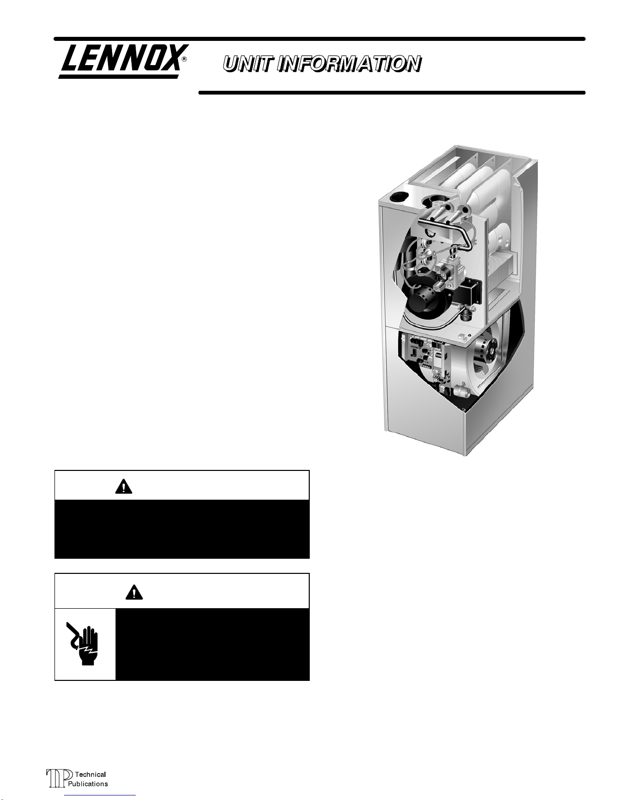
G32 series units are high−efficiency upflow gas furnaces
manufactured with DuralokPlus aluminized steel clam
shelltype heat exchangers. G32 units are available in
heating capacities of 75,000 to 125,000 Btuh and cooling
applications up to 5 tons. Refer to Engineering Handbook
for proper sizing.
Units are factory equipped for use with natural gas only. LP
kits are available. All G32−1 through −4 model units feature
the Lennox SureLight silicon nitride ignition system. G32−5
and later model units feature the SureLight two stage inte
grated control board. The G32 units meet the California Nitro
gen Oxides (NOx) Standards and California Seasonal Effi
ciency requirements without modification. All units use a two−
stage gas valve along with a two−stage combustion air blow
er. The gas valve is redundant to assure safety shut−off as re
qu ir ed b y A . G. A . o r C. G. A .
G32
Corp. 9729−L12
revised 03−2003
Information contained in this manual is intended for use by
qualified service technicians only. All specifications are
subject to change. Procedures outlined in this manual are
presented as a recommendation only and do not super
sede or replace local or state codes. In the absence of local
or state codes, the guidelines and procedures outlined in
this manual (except where noted) are recommended only.
WARNING
Improper installation, adjustment, alteration, service
or maintenance can cause property damage, person
al injury or loss of life. Installation and service must
be performed by a qualified installer or service
agency.
WARNING
Electric shock hazard. Can cause injury
or death. Before attempting to perform
any service or maintenance, turn the
electrical power to unit OFF at discon
nect switch(es). Unit may have multiple
power supplies.
TABLE OF CONTENTS
General 1. . . . . . . . . . . . . . . . . . . . . . . . . . . . . . . . . . . . . .
Specifications 2. . . . . . . . . . . . . . . . . . . . . . . . . . . . . . . . .
Blower Data 3. . . . . . . . . . . . . . . . . . . . . . . . . . . . . . . . . .
High Altitude 4. . . . . . . . . . . . . . . . . . . . . . . . . . . . . . . . . .
Vent Table 4. . . . . . . . . . . . . . . . . . . . . . . . . . . . . . . . . . . .
I Unit Components 6. . . . . . . . . . . . . . . . . . . . . . . . . . . . .
II Placement and Installation 18. . . . . . . . . . . . . . . . . . . .
III Start Up 26. . . . . . . . . . . . . . . . . . . . . . . . . . . . . . . . . . . .
VI Heating System Service Checks 27. . . . . . . . . . . . . .
V Typical Operating Pressures 29. . . . . . . . . . . . . . . . . .
VI Maintenance 30. . . . . . . . . . . . . . . . . . . . . . . . . . . . . . .
VII Wiring Diagrams and Operating Sequence 34. . . . .
VIII Trouble Shooting Guide SureLight Control 51. . . . .
Page 1
1998 Lennox Industries Inc.
Litho U.S.A.
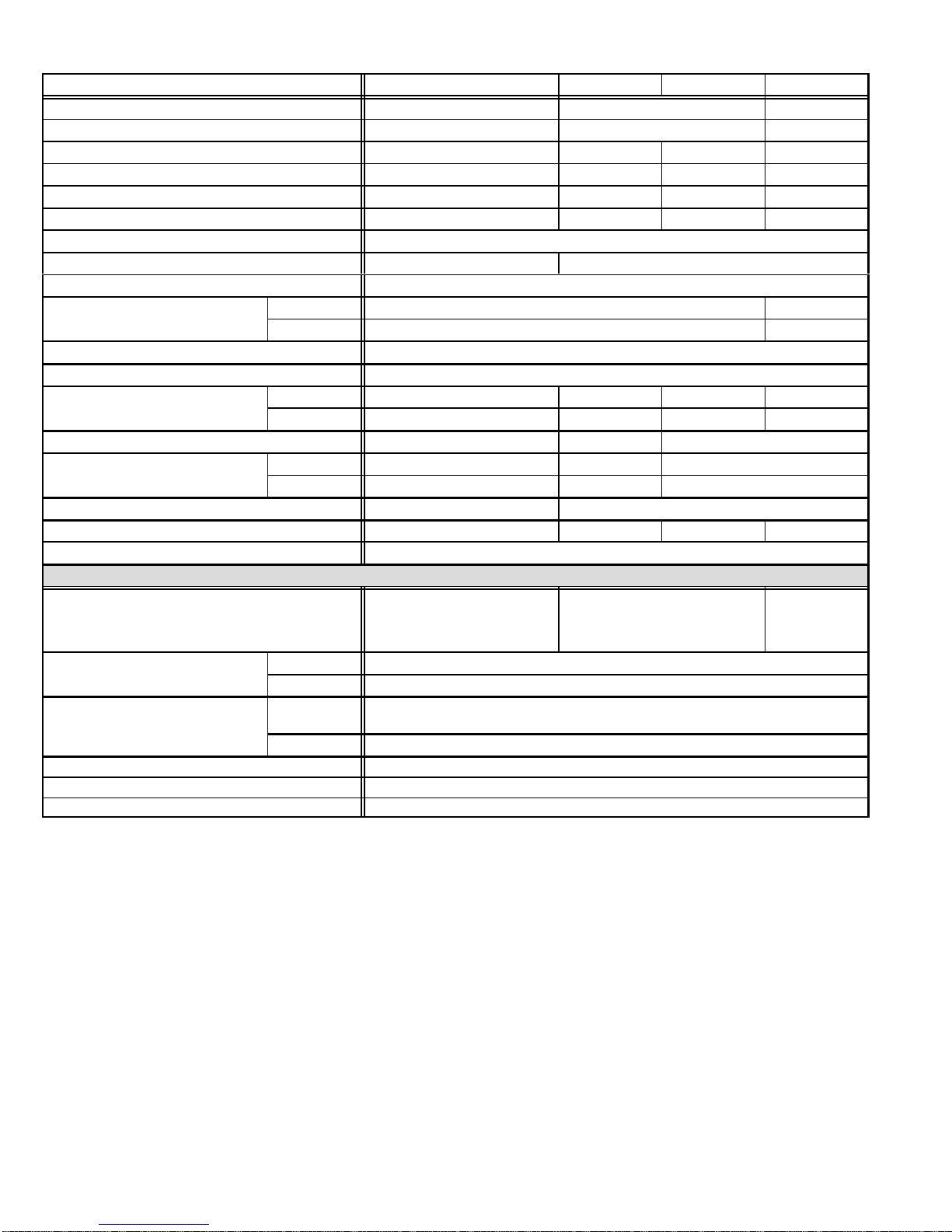
SPECIFICATIONS
Blower wheel nominal
g
Nominal cooling
Vent/Intake Air Roof
Model No. G32Q3−75 G32Q3/4−100 G32Q4/5−100 G32Q4/5−125
Input Btuh (kW) − High 75,000 (22.0) 100,000 (29.3) 125,000 (36.6)
Input Btuh (kW) − Low 51,000 (15.0) 68,000 (19.9) 85,000 (24.9)
Output Btuh (kW) − High 68,850 (20.2) 93,200 (27.3) 92,400 (27.1) 116,375 (34.1)
Output Btuh (kW) − Low 47,275 (13.9) 63,716 (18.7) 63,375 (18.6) 80,070 (23.5)
A.F.U.E. 93.0% 93.7% 93.2% 94.2%
California Seasonal Efficiency 87.3% 89.0% 87.0% 88.9%
Exhaust pipe connection (PVC) diameter in. (mm) 2 (51)
Intake pipe connection (PVC) diameter in. (mm) 2 (51) 3 (76)
Condensate drain connection (PVC) in. (mm) 1/2 (12.7)
Temperature rise range F (C)
High static certified by (A.G.A./C.G.A.) in. wg. (Pa) .50 (125)
Gas Piping Size I.P.S. − Natural − in. (mm) 1/2 (12.7)
Blower wheel nominal
diameter x width
Blower motor output hp (W) 1/3 (249) 1/2 (373) 3/4 (560)
Nominal coolin
that can be added
No. & size of filters − in. (mm) (1) 14 x 25 x 1 (356 x 635 x 25) (1) 20 x 25 x 1 (508 x 635 x 25)
Shipping weight lbs. (kg) 1 package 157 (71) 186 (84) 198 (90) 218 (99)
Electrical characteristics 120 volts 60 hertz 1 phase (all models) (less than 12 amps)
Concentric Vent/Intake Air/Roof Termination Kit (optional) 60G77 1 1/2 inch (38 mm) 33K97 2 inch (51 mm)
Vent/Intake Air Roof
Termination Kit (optional) vent size
Vent/Intake Air Wall
Termination Kit (optional) vent size
Condensate Drain Heat Cable 26K68 6 ft. (1.8 m) − 26K69 24 ft. (7.3 m) − 26K70 50 ft. (15.2 m)
Heat Cable Tape 39G04 − 1/2 in. (38 mm) fiberglass or 39G03 − 2 in. (25 mm) aluminum foil (1 roll)
L.P. KIt 34L29 (−1, −2 units) 11M55 (−3 units)
Annual Fuel Utilization Efficiency based on U.S. DOE test procedures and FTC labeling regulations. Isolated combustion system rating for non−weatherized furnaces.
Meets California Nitrogen Oxides (NO
Polyurethane frame type filter.
Determine from venting tables proper intake and exhaust pipe size and termination kit required.
NOTE − 2 inch x 3 inch (51 mm x 76 mm) adaptor is furnished with −100 and −125 furnaces for exhaust pipe connection.
Low Fire 30 − 60 (17 − 33) 35 − 65 (19 − 36)
High Fire 40 − 70 (22 − 39) 50 − 80 (28 − 44)
in. 10 x 8 10 x 10 11−1/2 x 9 11−1/2 x 9
mm 254 x 203 254 x 254 292 x 229 292 x 229
Tons 1 to 3 2 to 4 3−1/2 to 5
kW 3.5 to 10.6 7.0 to 14.1 12.3 to 17.6
OPTIONAL ACCESSORIES (Must Be Ordered Extra)
2 inch (51 mm) 15F75
3 inch (76 mm) 44J41
2 inch (51 mm)
15F74 (ring kit) 22G44 (close couple) 30G28 (WTK close couple)
30G79 (WTKX close couple with extension riser)
3 inch (76 mm) 44J40 (close couple) 81J20 (WTK close couple)
) Standard and California Seasonal Effieciency requirements.
x
33K97 − 2 inch
(51 mm)
60L46 − 3 inch
(76 mm)
Page 2
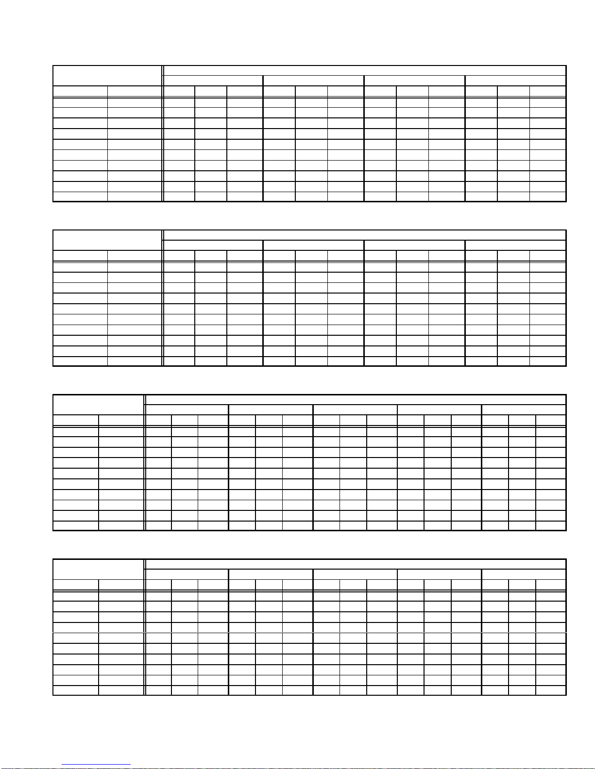
BLOWER/WATTS DATA
External Static
External Static
External Static
External Static
G32Q3−75 BLOWER PERFORMANCE
External Static
Pressure
in. w.g. Pa cfm L/s Watts cfm L/s Watts cfm L/s Watts cfm L/s Watts
0 0 1490 705 650 1340 630 540 1060 500 440 870 410 360
.10 25 1435 675 625 1305 615 515 1050 495 425 865 410 350
.20 50 1385 655 605 1260 595 490 1025 485 405 850 400 335
.30 75 1330 630 580 1215 575 470 1000 470 385 835 395 325
.40 100 1260 595 560 1160 545 445 965 455 365 810 380 310
.50 125 1200 565 540 1100 520 420 920 435 345 770 365 290
.60 150 1125 530 515 1035 490 400 870 410 325 735 345 280
.70 175 1035 490 495 960 455 375 780 370 305 685 325 265
.80 200 935 440 475 865 410 345 725 340 285 − − − − − − − − − − − −
.90 225 805 380 445 630 295 295 540 255 240 − − − − − − − − − − − −
NOTE All air data is measured external to unit with 1 in. (25 mm) cleanable foam filter (not furnished) in place. Also see Filter Air Resistance table.
High Medium−High Medium−Low Low
G32Q3/4−100 BLOWER PERFORMANCE
External Static
Pressure
in. w.g. Pa cfm L/s Watts cfm L/s Watts cfm L/s Watts cfm L/s Watts
0 0 2065 975 920 1760 830 735 1570 740 655 1245 590 520
.10 25 2000 945 875 1730 815 705 1550 730 625 1240 585 490
.20 50 1925 910 845 1685 795 675 1515 715 590 1225 580 470
.30 75 1840 870 800 1625 765 630 1475 695 565 1210 570 455
.40 100 1740 820 760 1550 730 595 1415 670 535 1165 550 430
.50 125 1650 780 730 1460 690 560 1335 630 500 111 0 525 405
.60 150 1545 730 700 1370 645 530 1260 595 475 1045 495 385
.70 175 1420 670 660 1250 590 495 1170 550 445 950 450 355
.80 200 1270 600 620 111 0 525 445 1025 485 395 825 390 325
.90 225 1045 495 560 965 455 405 885 420 360 700 330 290
NOTE All air data is measured external to unit with 1 in. (25 mm) cleanable foam filter (not furnished) in place. Also see Filter Air Resistance table.
High Medium−High Medium−Low Low
Air Volume and Motor Watts at Specific Blower Taps
Air Volume and Motor Watts at Specific Blower Taps
G32Q4/5−100 BLOWER PERFORMANCE
External Static
Pressure
in. w.g. Pa cfm L/s Watts cfm L/s Watts cfm L/s Watts cfm L/s Watts cfm L/s Watts
0 0 2400 1135 1255 2185 1030 1070 1940 915 905 1740 820 765 1570 740 665
.10 25 2350 111 0 1230 2150 1015 1055 1920 905 885 1710 805 755 1525 720 645
.20 50 2290 1080 1185 2105 995 1025 1875 885 865 1685 795 740 1505 710 640
.30 75 2225 1050 1170 2060 970 1005 1845 870 850 1655 780 730 1485 700 630
.40 100 2165 1020 1130 2010 950 985 1805 850 835 1620 765 720 1450 685 620
.50 125 2105 995 1115 1950 920 960 1755 830 810 1585 750 700 1415 670 605
.60 150 2040 965 1080 1895 895 940 1700 800 790 1540 725 690 1380 650 595
.70 175 1955 925 1045 1820 860 915 1640 775 775 1475 695 670 1340 630 590
.80 200 1850 875 1005 1730 815 885 1580 745 755 1430 675 660 1290 610 580
.90 225 1770 835 985 1650 780 855 1505 710 740 1370 645 645 1225 580 565
NOTE All air data is measured external to unit with 1 in. (25 mm) cleanable foam filter (not furnished) in place. Also see Filter Air Resistance table.
High Medium−High Medium Medium−Low Low
Air Volume and Motor Watts at Specific Blower Taps
G32Q4/5−125 BLOWER PERFORMANCE
External Static
Pressure
in. w.g. Pa cfm L/s Watts cfm L/s Watts cfm L/s Watts cfm L/s Watts cfm L/s Watts
0 0 2400 1135 1210 2175 1025 1040 1965 925 895 1790 845 780 1610 760 670
.10 25 2315 1090 1175 2125 1005 1025 1930 910 875 1760 830 770 1580 745 660
.20 50 2255 1065 1150 2080 980 1000 1880 885 860 1740 820 755 1550 730 645
.30 75 2195 1035 1130 2030 960 975 1840 870 835 1710 805 750 1520 715 635
.40 100 2120 1000 1100 1970 930 960 1790 845 815 1665 785 730 1495 705 630
.50 125 2050 965 1080 1910 900 934 1745 825 800 1620 765 715 1460 690 620
.60 150 1985 935 1050 1840 870 905 1685 795 785 1565 740 705 1415 670 610
.70 175 1885 890 1020 1770 835 890 1635 765 775 1515 715 685 1370 645 595
.80 200 1815 855 1005 1690 800 860 1570 740 750 1450 685 670 1315 620 580
.90 225 1735 820 980 1615 760 835 1485 700 725 1385 655 655 1245 590 565
NOTE All air data is measured external to unit with 1 in. (25 mm) cleanable foam filter (not furnished) in place. Also see Filter Air Resistance table.
High Medium−High Medium Medium−Low Low
Air Volume and Motor Watts at Specific Blower Taps
Page 3
BLOWER DATA
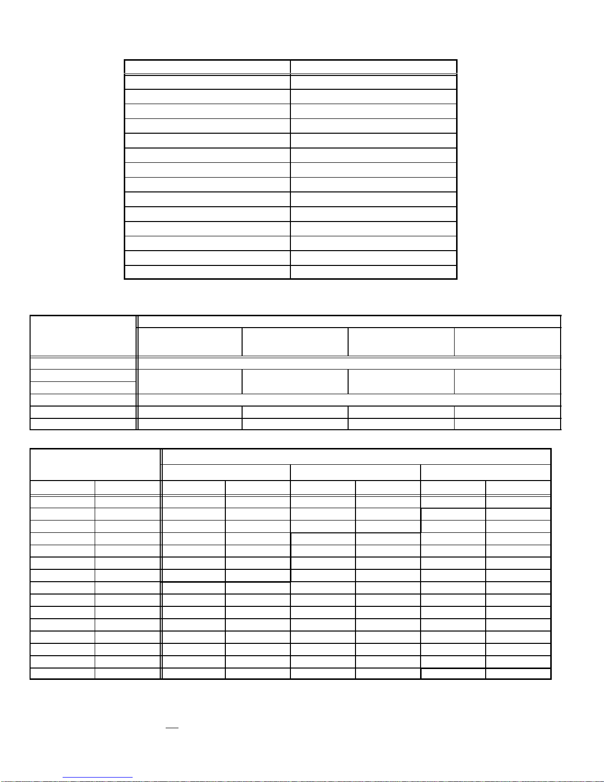
FILTER AIR RESISTANCE
cfm (L/s) in. w.g. (Pa)
0 (0) 0.00 (0)
200 (95) 0.01 (0)
400 (190) 0.03 (5)
600 (285) 0.04 (10)
800 (380) 0.06 (15)
1000 (470) 0.09 (20)
1200 (565) 0.12 (30)
1400 (660) 0.15 (35)
1600 (755) 0.19 (45)
1800 (850) 0.23 (55)
2000 (945) 0.27 (65)
2200 (1040) 0.33 (80)
2400 (1130) 0.38 (95)
2600 (1225) 0.44 (110)
No gas pressure adjustment is needed when operating from 0 to 4500 ft. (0 to 8 m). See below for correct manifold pressures for altitudes
greater that 4500 ft. (1372 m) for natural and L.P. gas.
Manifold Absolute Pressure (outlet) in. w.g. (kPa)
Model No.
0 to 4500 ft. (0 to 1372 m)
above sea level
G32−75 natural no adjustment
G32−100 natural
G32−125 natural
3.5 (0.88) 3.4 (0.85) 3.3 (0.82) 3.2 (0.80)
G32−75 L.P. no adjustment
G32−100 L.P. 7.5 (0.19) 7.3 (0.185) 7.1 (0.180) 7.0 (0.177)
G32−125 L.P. 7.5 (0.19) 7.3 (0.185) 7.1 (0.180) 7.0 (0.177)
4501 to 5500 ft.
(1373 to 1676 m)
above sea level
5501 to 6500 ft.
(1677 to 1981 m)
above sea level
6501 to 7500 ft.
(1982 to 2286 m)
above sea level
INTAKE AND EXHAUST PIPE VENTING TABLE
HIGH ALTITUDE INFORMATION
Vent Pipe
Maximum
Equivalent Length
75,000 Btuh (22.0 kW) 100,000 Btuh (29.3 kW) 125,000 Btuh (36.6 kW)
Feet Meters in. mm in. mm in. mm
15 4.6 2 51 2 51 2 51
20 6.1 2 51 2 51 3 76
25 7.6 2 51 2 51 3 76
30 9.1 2 51 3 51 3 76
40 12.2 2 51 3 51 3 76
50 15.2 2 51 3 51 3 76
55 16.8 2 51 3 76 3 76
60 18.3 3 76 3 76 3 76
70 21.3 3 76 3 76 3 76
80 24.4 3 76 3 76 3 76
90 27.4 3 76 3 76 3 76
100 30.5 3 76 3 76 3 76
110 33.5 3 76 3 76 3 76
120 36.6 3 76 3 76 3 76
130 39.6 3 76 3 76 − − − − − − − −
MINIMUM PIPE LENGTHS FOR FURNACES G32−75 5 feet (1.5 m) with two 90 elbows of 2 inch (51 mm) diameter pipe. (15 equivalent feet (4.6 m) total).
VENTING NOTES One 90elbow is equivalent to 5 feet (1.5 m) of straight vent pipe.
Two 45 elbows are equal to one 90 elbow.
One 45 elbow is equivalent to 2.5 feet (.75 m) of straight vent pipe.
One foot (305 mm) length of 2 in. (51 mm) diameter pipe is equivalent to 8 feet (2.4 m) of 3 in. (76 mm) diameter pipe.
Intake and Exhaust pipes must be the same diameter.
2 inch x 3 inch (51 mm x 76 mm) adaptor is furnished with −100 and −125 furnaces for exhaust pipe connection.
Exhaust pipe must terminate with 1−1/2 inch (38 mm) diameter pipe for furnaces using1−1/2 (38 mm) or 2 inch (51 mm) diameter pipe runs.
Exhaust pipe must terminate with 2 inch (51 mm) diameter pipe for furnaces using 3 inch (76 mm) diameter pipe runs.
G32−100 5 feet (1.5 m) with two 90 elbows of 2 inch (51 mm) diameter pipe. (15 equivalent feet (4.6 m) total).
G32−125 5 feet (1.5 m) with two 90 elbows of 2 inch (51 mm) diameter pipe. (15 equivalent feet (4.6 m) total).
Minimum Vent Pipe Diameter Required
Page 4
FRESH AIR
INTAKE FITTING
BURNER BOX
ASSEMBLY
PATCH
PLATE
FLAME SIGHT
GLASS
BURNER
BOX
COVER
GLASS FIBER GASKET
LOW HEAT
DIFFERENTIAL
PRESSURE
DIFFERENTIAL
TWOSTAGE
GAS VALVE AND
MANIFOLD
SWITCH
HIGH HEAT
PRESSURE
SWITCH
(−75 only)
G32 PARTS ARRANGEMENT
FLUE COLLAR
WARM
HEADER
(COLLECTOR)
BOX
PATCH PLATE WITH
BARBED FITTING
AND FLAME
ROLL−OUT SWITCH
DuralokPlus
HEAT EXCHANGER
ASSEMBLY
TM
TOP CAP
CABINET
FLUE
TRANSITION
SUPPLY
AIR
BLOWER
BURNER
ACCESS
PANEL
BLOWER
ACCESS
DOOR
TWO−SPEED
COMBUSTION AIR
INDUCER
COMBUSTION
AIR
ORIFICE
COLD HEADER
(COLLECTOR)
BOX
PRIMARY LIMIT
(ALTERNATE STYLES)
CONDENSER COIL
CONTROL TRANSFORMER
CONTROL VOLTAGE
CIRCUIT BREAKER
SURELIGHTTM TWO−STAGE
INTEGRATED CONTROL BOARD
DOOR INTERLOCK SWITCH
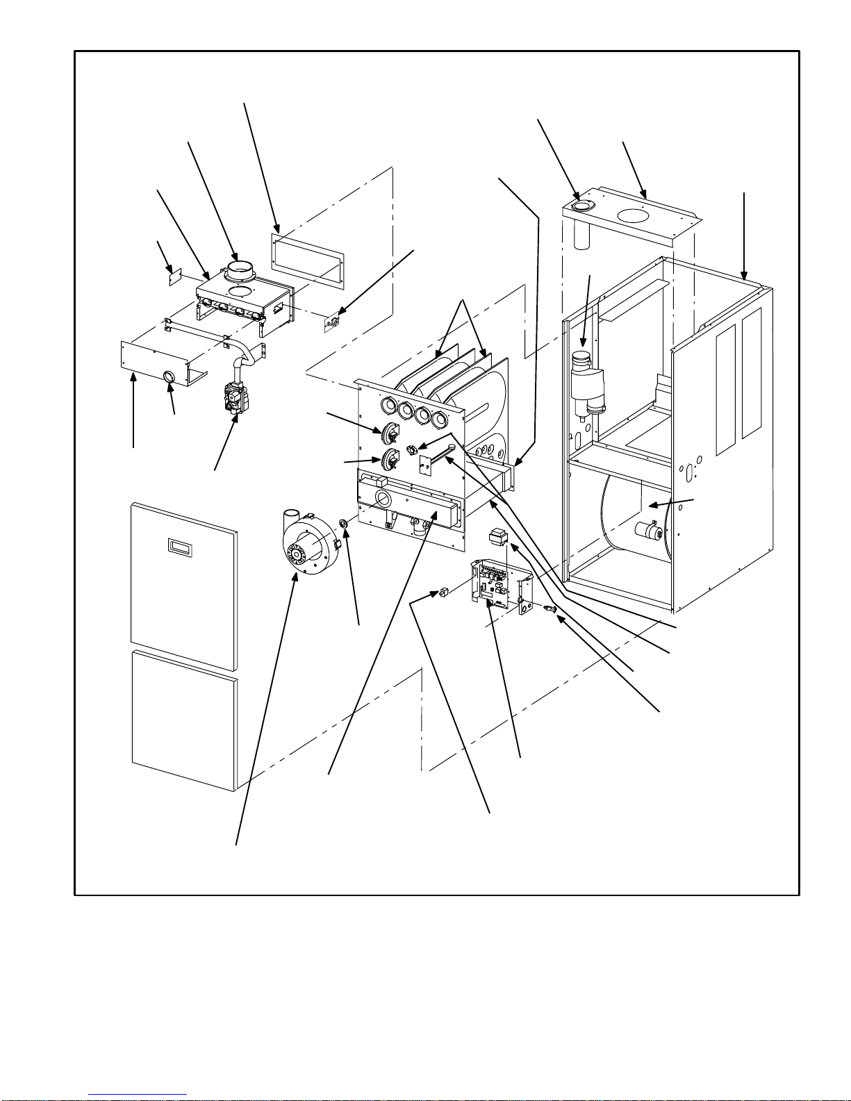
FIGURE 1
Page 5
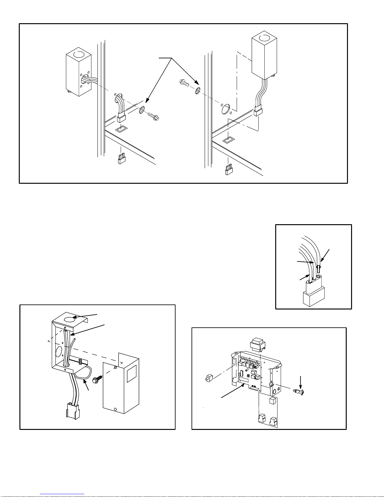
OUTSIDE INSTALLATION
MAKEUP BOX
MAKEUP BOX INSTALLATION
Box may be installed inside or outside cabinet and
may be installed on left side or right side of cabinet
STAR WASHERS
MUST BREAK
PAINT ON UNIT
CABINET FOR
PROPER GROUND.
UNIT
CABINET
INSIDE INSTALLATION
MAKEUP BOX
Line Voltage Enters Through
Knockout In MakeUp Box.
J69 Passes Through Side
Knockout Into Side Of Unit.
JACK J69
BLOWER MULLION
PLUG P69
FIGURE 2
I−UNIT COMPONENTS
G32 unit components are shown in figure 1. The gas valve,
ignition control and burners can be accessed by removing the
burner access panel. The blower and blower controls can be
accessed by removing the blower access door.
G32 units are designed for bottom and side return air. The
panels are designed to be knockedout (bottom return) or
cutout (side return) as required for return air duct connec
tion.
A−MakeUp Box (Figure 3)
The line voltage makeup box is shown in figure 3. The box
may be installed inside or outside the unit and may be installed
on the unit left or right side (figure 2).
Line Voltage Enters MakeUp
Box Through Side Of Unit and
J69 Passes Through Bottom
Knockout in MakeUp Box.
BLOWER MULLION
An accessory (brown) output wire is provided with the make
up box. The wire provides a 120V connection for optional ac
cessories such as electronic air cleaner or humidifier. If used,
the wire is field installed in J69 jack plug by inserting the pin of
the brown wire into the open
socket of the jack. See figure 4.
120V accessories rated up to 4
amps total may be connected
to this wire. The neutral leg of
the accessory is connected to
INSTALLING BROWN
ACCESSORY WIRE TO J69
BROWN
WHITE
NEUTRAL
the neutral white wire in the
makeup box. The accessory
terminal is energized whenev
er the blower is in operation.
BLACK
J69
MAKEUP BOX
POWER ENTRY KNOCKOUT
BOX
GROUND
JACK J69
to blower deck
Box may be installed inside or outside unit. See Figure 2.
TO BLOWER MULLION
120V LINE VOLTAGE
PIGTAIL CONNECTIONS
UNIT
FIGURE 3
COVER
B−Control Box Components
G32−1 / −4 UNIT CONTROL BOX
DOOR
INTERLOCK
SWITCH
SURELIGHT
CONTROL
FIGURE 5
Page 6
FIGURE 4
TRANSFORMER
CIRCUIT
BREAKER
TWOSTAGE
CONTROL
BOARD
Integrated ignition and blower control components (A92),
unit transformer (T1) and 24V circuit breaker (CB8) are lo
cated in the control box. In addition, a door interlock switch
(S51) is located in the control box. Jackplugs allow the con
trol box to be easily removed for blower service.
1. Control Transformer (T1)
A transformer located in the control box provides power to
the low voltage 24volt section of the unit. Transformers on
all models are rated 40VA with a 120V primary and a 24V
secondary.
2. Circuit Breaker (CB8)
A 24V circuit breaker is also located in the control box. The
switch provides overcurrent protection to the transformer
(T1). The breaker is rated 3A at 32V. If the current exceeds
this limit the breaker will trip and all unit operation will shut
down. The breaker can be manually reset by pressing the
button on the face.
3.Door Interlock Switch (S51)
A door interlock switch rated 14A at 125VAC is located on
the control box. The switch is wired in series with line volt
age. When the blower door is removed the unit will shut
down.
4.Flame Sensor
A flame sensor is located on the left side of the burner sup
port. See figure 6. The sensor is mounted on a bracket in
the burner support and the tip protrudes into the flame en
velope of the left−most burner. The sensor is fastened to
burner supports and can be removed for service without re
moving any part of the burners. During operation, flame is
sensed by current passed through the flame and sensing
electrode. The SureLight control allows the gas valve to re
main open as long as flame signal is sensed.
SENSOR
3/8"
FIGURE 6
NOTE − The G32 furnace contains electronic compo
nents that are polarity sensitive. Make sure that the fur
nace is wired correctly and is properly grounded.
IGNITOR
5/16"
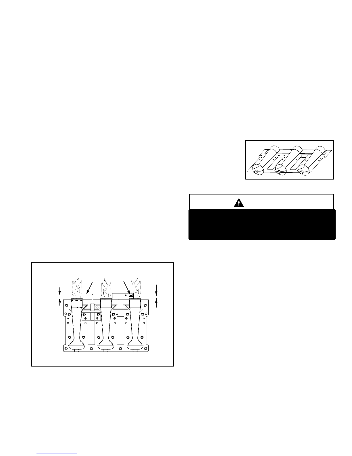
5.Burners
All units use inshot burners (see figure 7). Burners are factory
set and do not require adjustment. A sig ht glas s is furnis h e d
in the burner box assembly for flame viewing. Always
operate the unit with the burner box cover in place. Burn
ers can be removed as an assembly for service. Burner main
tenance and service is detailed in the MAINTENANCE sec
tion of this manual. Each burner uses an orifice which is pre
cisely matched to the burner input (see nameplate for orifice
size). The orifice is threaded into the burner manifold. The
burner is supported by the orifice and will easily slide off for
service. Each orifice and burner are sized specifically to the
unit. Refer to Lennox Repair Parts Listing for correct sizing
information. A flame retention ring in the end of each burner
maintains correct flame length and shape and keeps the flame
from lifting off the burner head. In addition, the burner entrance
to each clamshell is fitted with a corbel cup (orifice) used to
direct the flow of
combustion prod
ucts.
TYPICAL BURNER ASSEMBLY
FIGURE 7
DANGER
Shock hazard.
Disconnect power before servicing. Control is not
field repairable. If control is inoperable, simply re
place entire control.
6.SureLight Ignition System A92
All G32−1 through −4 units are equipped with the Lennox
SureLight ignition system. The system consists of ignition
control board (figure 8 with control terminal designations
in table 1) and ignitor (figures 6 and 9). The board and igni
tor work in combination to ensure furnace ignition and ig
nitor durability. The SureLight integrated board controls
all major furnace operations. The board also features two
LED lights for troubleshooting (and two accessory termi
nals rated at (4) four amps. See table 2 for troubleshooting
diagnostic codes.
NOTE − Do not remove blower access panel to read Sur
elight LED lights. A sight glass is provided on the access
panel for viewing.
Tables 3 and 4 show jack plug terminal designations. Units
equipped with the SureLight board can be used with either
electronic or electro−mechanical thermostats without
modification. The SureLight ignitor is made of durable sili
con−nitride. Ignitor longevity is also enhanced by voltage
ramping by the control board. The board finds the lowest
ignitor temperature which will successfully light the burn
er, thus increasing the life of the ignitor.
Page 7
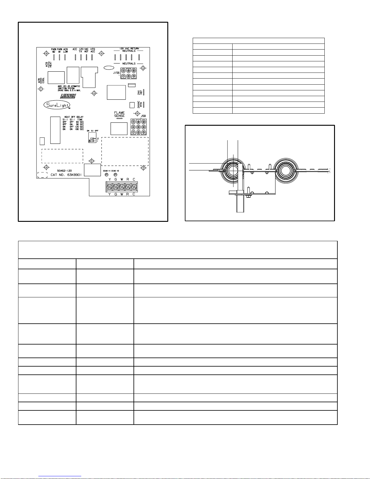
SURELIGHT CONTROL BOARD
TABLE 1
SURELIGHT CONTROL TERMINAL DESIGNATIONS
ACB COOL
ACB HEAT
PARK
ACB LOW
ACC
TX
HOT
HTG ACC
NEUTRALS
24VAC HOT
24VAC RTN
FLAME SENSE
Blower − Cooling Speed (Line Volt)
Blower − Heating Speed (Line Volt)
Alternate Blower Speeds (Dead)
Continuous Low Speed Blower
Accessory Terminal (Line Volt)
120VAC Hot to Transformer
120VAC Hot Input
Heat Only Accessory (Line Volt)
120VAC Neutrals
24VAC Hot from Transformer
24VAC Return from Transformer
Flame Sense Terminal
SURELIGHT IGNITOR
MEASUREMENT IS TO I.D.
5/8"
OF RETENTION RING
13/32’
FIGURE 8
TABLE 2
DIAGNOSTIC CODES
MAKE SURE TO ID LED’S CORRECTLY: REFER TO INSTALLATION INSTRUCTIONS FOR CONTROL BOARD LAYOUT.
LED #1 LED #2 DESCRIPTION
SIMULTANEOUS
SLOW FLASH
SIMULTANEOUS FAST
FLASH
SLOW FLASH ON
OFF SLOW FLASH
ALTERNATING SLOW
FLASH
SLOW FLASH OFF
ON SLOW FLASH
ON
ON
OFF
FAST FLASH SLOW FLASH
SLOW FLASH FAST FLASH
ALTERNATING FAST
FLASH
SIMULTANEOUS
SLOW FLASH
SIMULTANEOUS FAST
ALTERNATING SLOW
ALTERNATING FAST
FLASH
FLASH
ON
OFF
ON
FLASH
Also signaled during cooling and continues fan.
Normal operation − signaled when heating demand initiated at thermostat.
Primary or Secondary limit open. Units with board 63K8901 or 24L85: Limit must
close within 5 trials for ignition or board goes into one hour limit Watchguard. Units
with board 56L83 or 97L48: Limit must close within 3 minutes or board goes into
Pressure switch open or has opened 5 times during a single call for heat; OR:
Blocked inlet/exhaust vent; OR: Condensate line blocked; OR: Pressure switch
closed prior to activation of combustion air blower.
Flame sensed without gas valve energized.
Rollout switch open. OR: 9 pin connector improperly attached.
Circuit board failure or control wired incorrectly.
Main power polarity reversed. Switch line and neutral.
Low flame signal. Measures below .61 microAmps. Replace flame sense rod.
Improper main ground or line voltage below 75 volts; OR: Broken ignitor; OR:
Power − Normal operation
one hour limit Watchguard.
Watchguard − burners fail to ignite.
Open ignitor circuit.
FIGURE 9
NOTE − Slow flash equals 1 Hz (one flash per second). Fast flash equals 3 Hz (three flashes per second). Drop out flame sense current < 0.21microAmps
Page 8
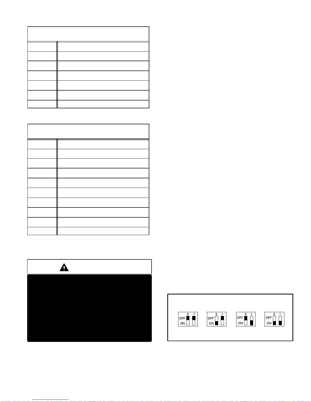
TABLE 3
SureLight BOARD J156 TERMINAL
PIN # FUNCTION
1 Ignitor
2
3
4
5
6
DESIGNATIONS
Not Used
Ignitor Neutral
Combustion Air Blower Line Voltage
Not Used
Combustion Air Blower Neutral
TABLE 4
SureLight BOARD J58 TERMINAL
PIN # FUNCTION
1 Primary Limit In
2
3
4
5
6
7
8
9
DESIGNATIONS
Gas Valve Common
Roll Out Switch Out
Gas Valve 24V
Pressure Switch In
Pressure Switch and Primary Limit Out
Not Used
Roll Out Switch In
Ground
ELECTROSTATIC DISCHARGE (ESD)
Precautions and Procedures
CAUTION
Electrostatic discharge can affect electronic
components. Take precautions during furnace
installation and service to protect the furnace’s
electronic controls. Precautions will help to
avoid control exposure to electrostatic dis
charge by putting the furnace, the control and
the technician at the same electrostatic poten
tial. Neutralize electrostatic charge by touching
hand and all tools on an unpainted unit surface,
such as the gas valve or blower deck, before per
forming any service procedure.
a−Electronic Ignition Figures 11 and 12
On a call for heat the SureLight control monitors the com
bustion air blower pressure switch. The control will not be
gin the heating cycle if the pressure switch is closed (by−
passed). Once the pressure switch is determined to be
open, the combustion air blower is energized. When the
differential in the pressure switch is great enough, the pres
sure switch closes and a 15−second pre−purge begins. If
the pressure switch is not proven within 2−1/2 minutes, the
control goes into Watchguard−Pressure Switch mode for a
5−minute re−set period.
After the 15−second pre−purge period, the SureLight ignitor
warms up for 20 seconds after which the gas valve opens
for a 4−second trial for ignition. G32 units with board 63K89,
24L85 or 56L83: the ignitor stays energized for the first sec
ond of the 4−second trial. G32 units with board 97L48: igni
tor stays energized for the full 4−second trial for ignition. If
ignition is not proved during the 4−second period, the con
trol will try four more times with an inter purge and warm−up
time between trials of 35 seconds. After a total of five trials
for ignition (including the initial trial), the control goes into
Watchguard−Flame Failure mode. After a 60−minute reset
period, the control will begin the ignition sequence again.
The SureLight control board has an added feature that pro
longs the life of the ignitor. After a successful ignition, the
SureLight control utilizes less power to energize the ignitor
on successive calls for heat. The control continues to ramp
down the voltage to the ignitor until it finds the lowest
amount of power that will provide a successful ignition. This
amount of power is used for 255 cycles. On the 256th call
for heat, the control will again ramp down until the lowest
power is determined and the cycle begins again.
b−Fan Time Control
The fan on time of 45 seconds is not adjustable. Fan off
time (time that the blower operates after the heat demand
has been satisfied) can be adjusted by flipping the dip
switches located on the SureLight integrated control. The
unit is shipped with a factory fan off setting of 90 seconds.
Fan off time will affect comfort and is adjustable to satisfy
individual applications. See figure 10.
FANOFF TIME ADJUSTMENT
60sec. 90sec. 120sec. 180sec.
To adjust fan−off timing, flip dip switch to desired setting.
FIGURE 10
Page 9
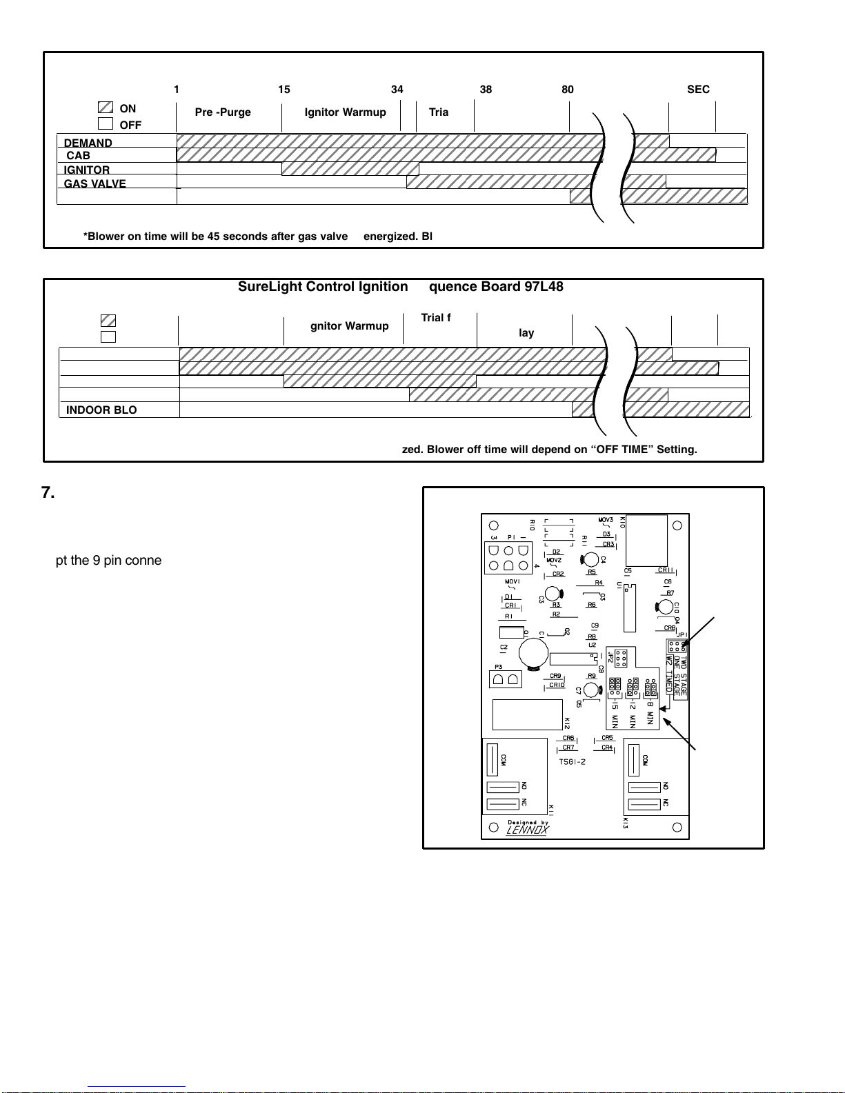
SureLight Control Ignition Sequence
ЙЙЙЙЙЙЙЙЙ
Board 56L83, 24L85, 63K89
1
ON
OFF
DEMAND
CAB
IGNITOR
GAS VALVE
INDOOR BLOWER
*Blower on time will be 45 seconds after gas valve is energized. Blower off time will depend on OFF TIME" Setting.
Pre −Purge Ignitor Warmup Trial for
15
34
35
Ignition
38
Blower On"
Delay
FIGURE 11
SureLight Control Ignition Sequence Board 97L48
15
ON
OFF
DEMAND
CAB
IGNITOR
GAS VALVE
INDOOR BLOWER
*Blower on time will be 45 seconds after gas valve is energized. Blower off time will depend on OFF TIME" Setting.
Pre −Purge Ignitor Warmup
341
Trial for
Ignition
38
Blower On"
Delay
FIGURE 12
5 SEC80
Post
Purge
5 SEC80
Post
Purge
7. Two−Stage Control (A86)
All G32−1 through −4 units are equipped with a two−stage
control board. Two different boards have been used. Board
43K9001 and board 25M3301 (figure 13) are identical, ex
cept the 9 pin connector on 43K9001 is replaced by two re
lays with quick connect terminals on 25M3301. The two−
stage board acts as a go between from the indoor thermo
stat to the SureLight ignition board. The board can be uti
lized in three modes: with a SINGLE−STAGE thermostat, a
TWO−STAGE thermostat or with a second−stage (high fire)
delay called W2 TIMED. The two−stage board is equipped
with a jumper (see figure 13) which changes operating
modes and a jumper which adjusts second−stage heat
delay during W2 TIMED mode.
While in the single−stage thermostat mode (one−stage
jumper setting), the unit will always operate on second−
stage heat. The combustion air blower (B6) will operate on
high speed and indoor blower (B3) will operate on heating
speed. While in the two−stage thermostat mode the unit will
operate on first−stage heat (low fire). The combustion air
blower (B6) and indoor blower will operate on low speed.
The unit will switch to second−stage heat (high fire) on call
from the indoor thermostat W2. While in the W2 TIMED
mode (factory setting 8 minutes) the unit will fire on first−
stage heat (low fire) with the combustion air blower (B6)
and indoor blower (B3) operating on low speed. After a set
time delay the unit switches to second−stage heat (high
fire). The combustion air blower and indoor blower also
switch to second−stage heat mode.
TWO−STAGE CONTROL BOARD 25M3301
MODE OF
OPERATION
JUMPER
W2 TIMED
ON DELAY
JUMPER
FIGURE 13
Page 10

WARNING
Shock hazard.
Disconnect power before servicing. Integrated
Control Board is not field repairable. If control is
inoperable, simply replace entire control.
Can cause injury or death. Unsafe operation will
result if repair is attempted.
8. Two Stage Integrated Control Board(A92)
All G32−5 units units are equipped with the Lennox two−
stage integrated SureLight control board. The system
consists of a ignition control board (figure 14 with control
terminal designations in tables 7, 8 and 9) and ignitor (fig
ure 9). The board and ignitor work in combination to en
sure furnace ignition and ignitor durability. The board con
trols all major furnace operations. The board features two
LED lights, DS1 and DS2 for troubleshooting. The board
also has two accessory terminals rated at (1) one amp
each. See table 10 for troubleshooting diagnostic codes.
Electronic Ignition
At the beginning of each heat cycle, SureLight control mon
itors the first stage and second stage combustion air induc
er prove switch. The control will not begin the heating cycle
if the first stage prove switch is closed (by−passed). Like
wise the control will not begin the second stage heating
cycle if the second stage prove switch is closed and will al
low first stage heat only. However if the second stage prove
switch closes during the first stage pre−purge, the control
will still respond to second stage heat. Once the first stage
prove switch is determined to be open, the combustion air
inducer is energized on low (first stage) heat speed. When
the differential in the prove switch is great enough, the
prove switch closes and a 15−second pre−purge begins. If
the switch is not proven within 2−1/2 minutes, the control
goes into Watchguard−Pressure Switch mode for a 5−min
ute re−set period.
After the 15−second pre−purge period, the SureLight ignitor
warms up for 20 seconds after which the gas valve opens
for a 4−second trial for ignition. The ignitor energizes during
the trial until flame is sensed. If ignition is not proved during
the 4−second period, the control will try four more times with
an inter purge and warm−up time between trials of 35 sec
onds. After a total of five trials for ignition (including the ini
tial trial), the control goes into Watchguard−Flame Failure
mode. After a 60−minute reset period, the control will begin
the ignition sequence again.
The SureLight control board has an added feature that pro
longs the life of the ignitor. After a successful ignition, the
SureLight control utilizes less power to energize the ignitor
on successive calls for heat. The control continues to ramp
down the voltage to the ignitor until it finds the lowest
amount of power that will provide a successful ignition. This
amount of power is used for 255 cycles. On the 256th call
for heat, the control will again ramp down until the lowest
power is determined and the cycle begins again.
Two Stage Operation / Thermostat Selection Jumper
The control can be utilized in two modes: SINGLE−STAGE
thermostat or TWO−STAGE thermostat. The thermostat
selection jumper E20, located just below dip switches 1
through 4 (figure 14), must be positioned for the particular
application. The jumper is factory set on TWO" for use
with a two−stage thermostat with two stage heat. Re−posi
tion jumper to SINGLE" for use with a single stage thermo
stat with two stage heat.
While in the single−stage thermostat mode (single jumper
setting), the burners will always fire on first−stage heat. The
combustion air inducer will operate on low speed and in
door blower will operate on low heat speed. After a field se
lectable 10 or 15 minute delay (dip switch 3), the unit will
switch to second stage heat. While in the two−stage ther
mostat mode (two jumper setting) the burners will fire on
first−stage heat. The combustion air inducer will operate on
low speed and indoor blower will operate on low heat
speed. The unit will switch to second−stage heat on call
from the indoor thermostat. If there is a simultaneous call
for W1 and W2 (first and second stage heat) the unit will fire
on first stage heat and will switch to second stage heat after
30 seconds of operation. See Sequence of Operation flow
charts in the back of this manual for more detail.
Dip Switch Settings
Dip Switches 1 and 2 − Heating Fan off Delay − The fan on
time of 45 seconds is not adjustable. Fan off time (time that
the blower operates after the heat demand has been satis
fied) can be adjusted by flipping the dip switches 1 and 2
located on the SureLight integrated control. The unit is
shipped with a factory fan off setting of 90 seconds. Fan off
time will affect comfort and is adjustable to satisfy individual
applications. For customized comfort, monitor the supply
air temperature once the heat demand is satisfied. Note the
supply air temperature at the instant the blower is de−ener
gized. Adjust the fan−off delay to achieve a supply air tem
perature between 90° − 110° at the instant the blower is de−
energized. (Longer delay times allow for lower air tempera
ture, shorter delay times allow for higher air temperature).
See table 5 for dip switch settings.
Page 11
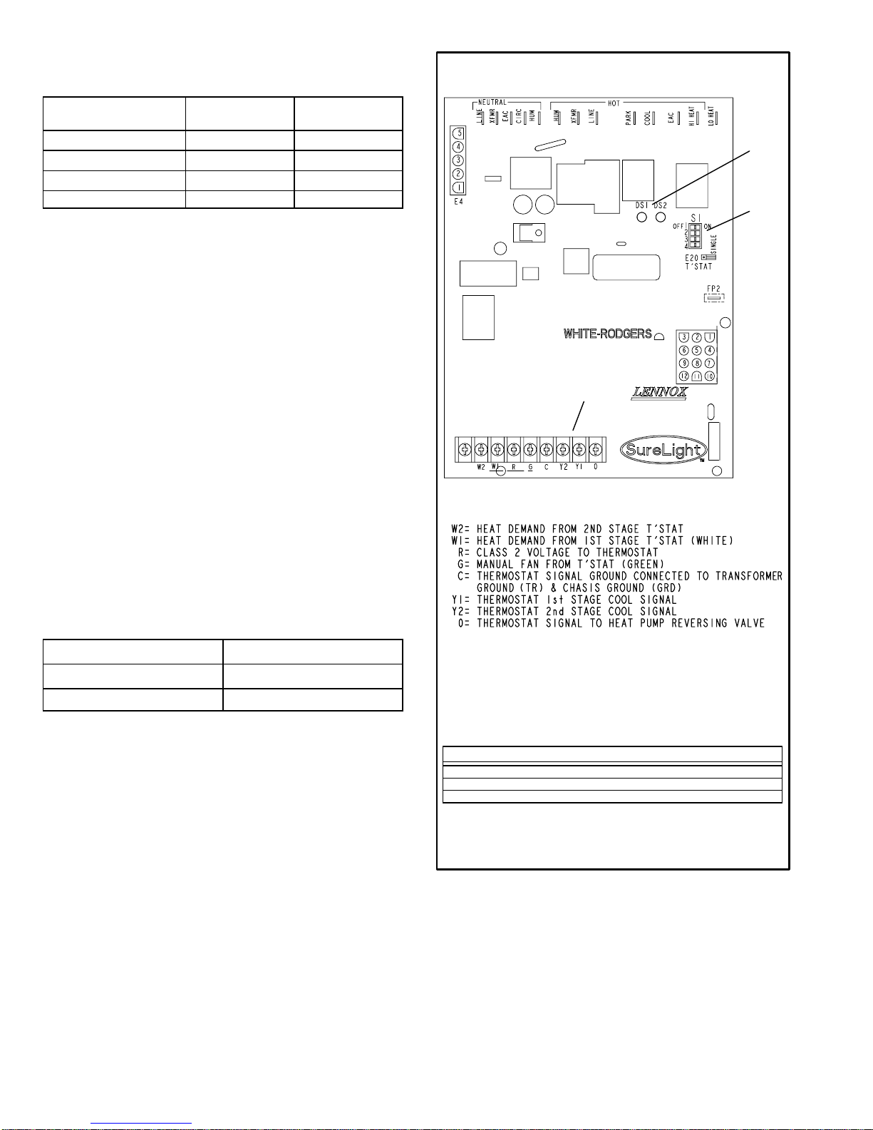
TABLE 5
Heating Fan Off Delay
TWO−STAGE INTEGRATED CONTROL BOARD
Delay (Seconds)
Switch 1 Switch 2
60 Off Off
90 Off On
120 On Off
180 On On
Switch 3 − Second Stage Delay (Used with Single−Stage
Thermostat Only) −− This switch is used to determine the
second stage on delay when a single−stage thermostat is
being used. The switch is factory−set in the ON position,
which provides a 10−minute delay before second−stage
heat is initiated. If the switch is toggled to the OFF position,
it will provide a 15−minute delay before second−stage heat
is initiated. This switch is only activated when the thermo
stat selector jumper is positioned for SINGLE−stage ther
mostat use.
Switch 4 − Cooling Fan off Delay − The fan on delay time
of 2 seconds is not adjustable. Fan off time (time that the
blower operates after the cool demand has been satisfied)
can be adjusted by flipping dip switch 4. The unit is shipped
with a factory fan off setting of 45 seconds. Fan off time will
affect comfort and is adjustable to satisfy individual ap
plications. See table 6 for cool fan off time settings.
TABLE 6
Cooling Fan Off Delay
Delay (Seconds) Switch 4
SENSOR
FACTORY−
INSTALLED
JUMPER
THERMOSTAT CONNECTIONS (TB1)
LEDs
DIP
SWITCHES
1 − 4
2 Off
45 On
Diagnostic LED’s (DS1 and DS2)
Two diagnostic LED’S are located on the two−stage inte
grated control board. See figure 14. These light flashes
correspond with the codes detailed in table 10.
Factory Installed Jumper Y1 to Y2
A factory−installed jumper from Y1 to Y2 terminals on the
integrated control board terminal strip must be removed for
two−stage cooling.
DIP SWITCH(ES) FUNCTION
1 and 2 Blower Off Delay (Heating Mode)
3 Second Stage ON Delay (Single−stage t’stat)
4 Blower Off Delay (Cooling Mode)
FIGURE 14
Page 12
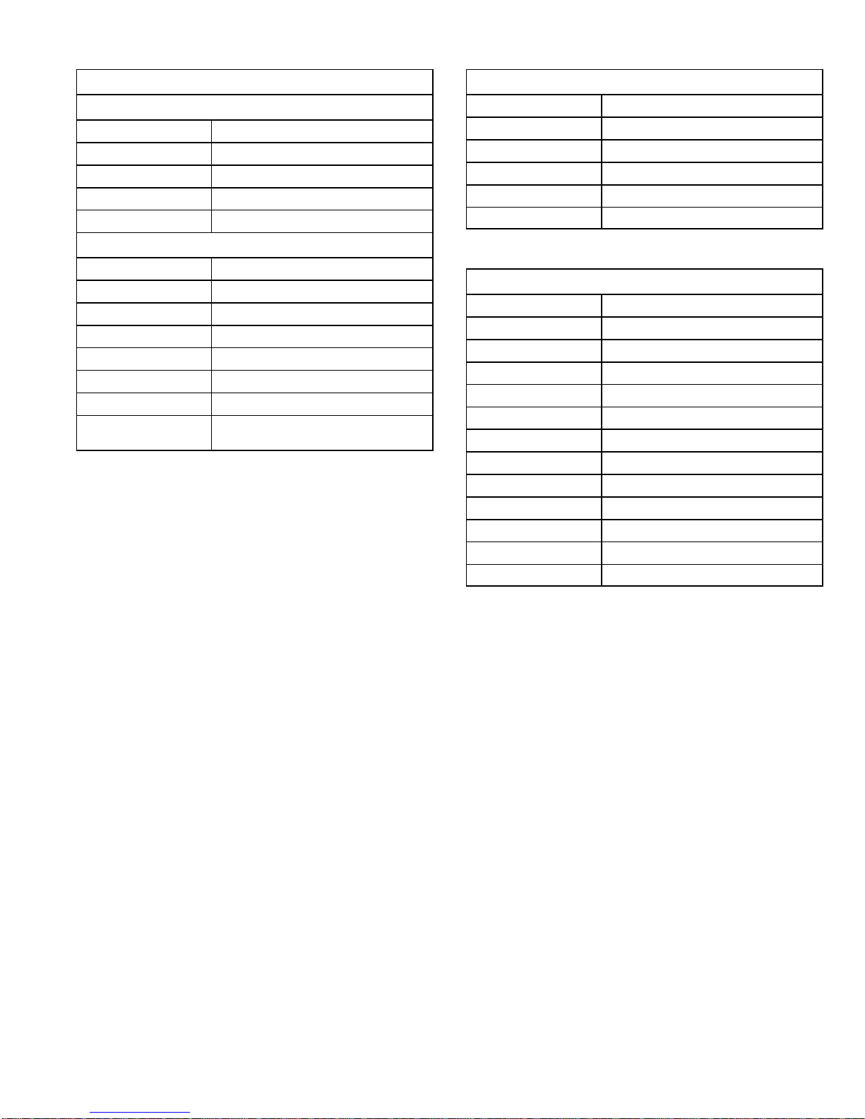
TABLE 7
TABLE 8
Integrated Control Board Terminals
120VAC Neutral
LINE Line
XFMR Transformer
EAC Electronic Air Cleaner
CIRC Indoor Blower
HUM Humidifier
120VAC Line
HUM Humidifier
XMFR Transformer
LINE Line
PARK For Unused Leads
COOL Cooling Speed
EAC Electronic Air Cleaner
HI HEAT High Heat Speed
LO HEAT Low Heat, Low Cool and Continuous Fan
Speed
Integrated Control Board 5 Pin Terminal
PIN # Function
1 Ignitor
2 Combustion Air Inducer High Speed
3 Combustion Air Inducer Low Speed
4 Combustion Air Inducer Neutral
5 Ignitor Neutral
TABLE 9
Integrated Control Board 12Pin Terminal
PIN # Function
1 Gas Valve 2nd Stage (High Fire)
2 Second Stage Prove Switch
3 Not Used
4 Ground
5 24V Hot
6 Primary Limit In
7 Gas Valve 1st stage (Low Fire)
8 Gas Valve Common
9 24V Neutral
10 Ground
11 Primary Limit Out
12 1st Stage Prove Switch
Page 13
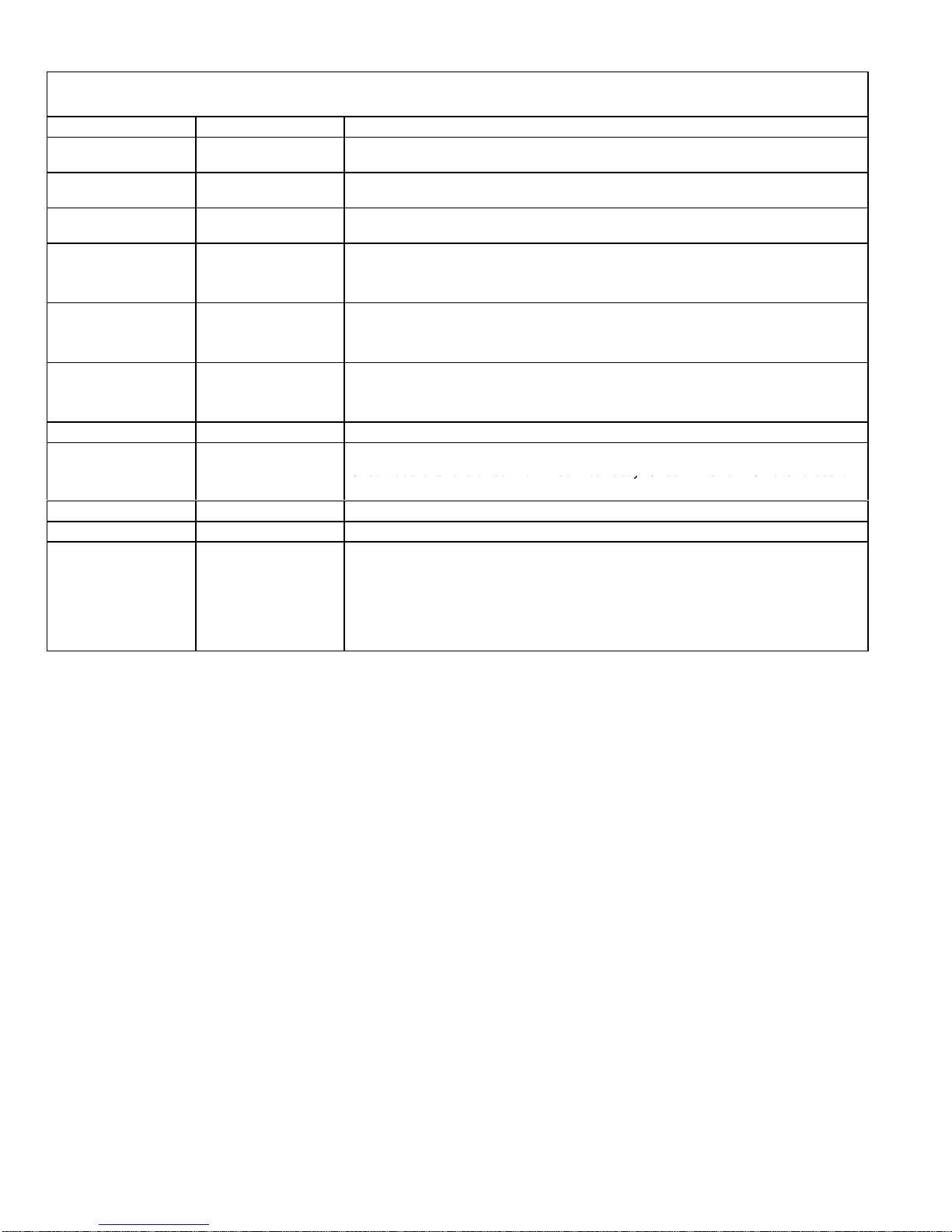
TABLE 10
ONONON
O
O
Circuit board failure or control wired incorrectly. Check 24 and 115 volts to board.
DIAGNOSTIC CODES
Diagnostic LEDs are labeled DS1 and DS2. See figure 14 for location of diagnostic LEDs.
DS1 DS2 DESCRIPTION
SIMULTANEOUS
SLOW FLASH
SIMULTANEOUS
FAST FLASH
SLOW FLASH ON
OFF SLOW FLASH
OFF FAST FLASH
ALTERNATING
SLOW FLASH
SLOW FLASH OFF Flame sensed without gas valve energized.
ON ON
OFF
FAST FLASH SLOW FLASH Main power polarity reversed. Switch line and neutral.
SLOW FLASH FAST FLASH Low flame signal. Measures below .23 microAmps. Replace flame sense rod.
ALTERNATING
FAST FLASH
SIMULTANEOUS
SLOW FLASH
SIMULTANEOUS
FAST FLASH
ALTERNATING
SLOW FLASH
OFF
ON
ALTERNATING
FAST FLASH
Power on − Normal operation.
Also signaled during cooling and continuous fan.
Normal operation − signaled when heating demand initiated at thermostat.
Primary limit or rollout switch open. Limits must close within 3 minutes or unit
goes in to 1 hour Watchguard.
Low−fire pressure switch open (G32Q−75 only);
OR: Blocked inlet/exhaust vent;
OR: Low pressure switch closed prior to activation of combustion air inducer.
High−fire pressure switch open
OR: Blocked inlet/exhaust vent;
OR: High pressure switch closed prior to activation of combustion air inducer.
Watchguard −− burners failed to ignite; OR limit open more than 3 minutes;
OR lost flame sense 5 times in one heating cycle;
OR pressure switch opened 5 times in one heating cycle.
Circuit board failure or control wired incorrectly. Check 24 and 115 volts to board.
The following conditions are sensed during the ignitor warm−up period only:
1) Improper main ground;
2) Broken ignitor; OR: Open ignitor circuit;
3) Line voltage below 75 volts.
(If voltage lower than 75 volts prior to ignitor warmup, control will signal waiting on
call from thermostat, and will not respond.
NOTE − Slow flash rate equals 1 Hz (one flash per second). Fast flash rate equals 3 Hz (three flashes per second).
Minimum flame sense current = 0.17− 0.22 microAmps.
Page 14
9.Blower Motors and Capacitors
6
All G32 units use direct drive blower motors. All motors used
are 120V permanent split capacitor motors to ensure maxi
mum efficiency. See table 11 for ratings.
TABLE 11
G32 BLOWER RATINGS 120V 1PH
BLOWER MOTOR HP CAP
G32Q3 1/3 5MFD 370V
G32Q3/4 1/2 7.5MFD 370V
G32Q4/5 3/4 40MFD 370V
10.Combustion Air Blower (B6)
All G32 units use a two−stage combustion air blower to move
air through the burners and heat exchanger during heating op
eration. The blower uses a 120VAC motor. The motor oper
ates during all heating operation and is controlled by the Sur
eLight integrated control A92 and the two−stage control board
A86. The combustion air blower operates for 15 seconds be
fore burner ignition (prepurge) and for 5 seconds after the gas
valve closes (postpurge). The combustion air blower operates
on low speed during first−stage heat (low fire), then switches to
high speed for second−stage heat (high fire).
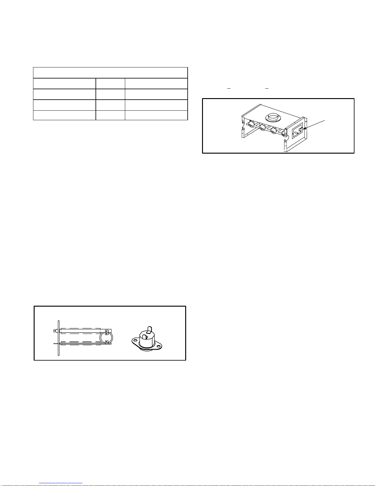
11.Primary Limit Control (S10) Figure 15
The primary limit (S10) on G32 units is located in the middle
of the heating vestibule panel. When excess heat is
sensed in the heat exchanger, the limit will open. If the limit
is tripped, the furnace control energizes the supply air
blower and de−energizes the gas valve. The limit automati
cally resets when unit temperature returns to normal. The
switch is factory set and cannot be adjusted.
SPADE CONNECTORS
G32 SERIES UNITS AND ALTERNATE STYLE
LIMIT CONTROL (S10) FOR
Units may be equipped with either style limit.
LIMIT
INSULATING COVER (s)
FIGURE 15
12.Flame Rollout Switch (S47)
Flame rollout switch S47 is a SPST N.C. high temperature limit
located on the right side of the burner box assembly (see figure
16). S47 is wired to the burner ignition control A92. When
S47 senses flame rollout (indicating a blockage in the
combustion passages), the flame rollout switch trips,
and the ignition control immediately closes the gas
valve. Switch S47 in all G32 units is factory preset to open
at 200F + 12F (93C + 6.7C) on a temperature rise. All
flame rollout switches are manually reset.
FLAME ROLLOUT SWITCH (S47)
FLAME ROLLOUT
SWITCH (S47)
FIGURE 1
13.Gas Valve
The G32 uses a gas valve manufactured by White Rodgers
or Honeywell. The valve is twostage internally redundant
to assure safety shut−off. If the gas valve must be replaced,
the same type valve must be used. The Honeywell valve
can be field converted to LP and is adjustable on both high
fire and low fire. WhiteRodgers supplies two separate
valves for natural and LP and is adjustable on high fire
ONLY.
24VAC terminals and gas control knob are located on top of
the valve. Terminals on the gas valve are connected to wires
from the SureLight integrated control and the two−stage con
trol. 24V applied to the terminals energizes the valve.
Inlet and outlet pressure taps are located on the valve. A regu
lator adjustment screw is located on the side of the valve. Re
fer to figure 37 in section III−START UP for location of valve
features.
100% Sealed Combustion
The burner box is completely sealed and operates under a
negative pressure. A pressure hose is connected from the
burner box to the gas valve regulator and differential pres
sure switch. The gas valve senses the pressure in the burn
er box and changes gas valve output based on changes in
burner box pressure. The intent is to compensate for differ
ent vent configurations which can greatly affect the rate of
the unit.
Page 15
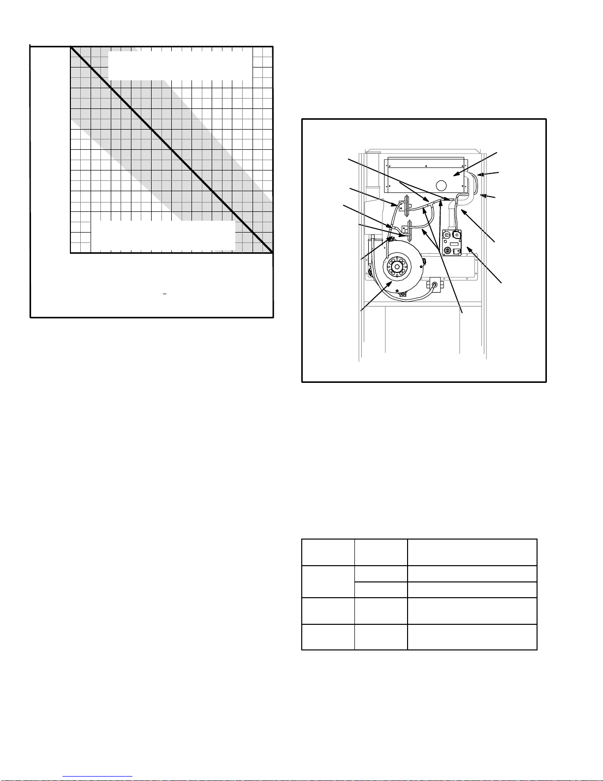
NORMAL OPERATION (Natural Gas Units)
75,000
3.5
3.4
3.3
3.2
AOPERATION AT THIS EXTREME
MAY INDICATE A BLOCKED
OUTLET OR OTHER PROBLEM
sure sensed by the switch is relative to the pressure in the
burner box. In order for the furnace to operate, the larger
negative must always be on the combustion air blower
side of the switch. If the flue or air inlet become obstructed
during operation, the switch senses a loss of pressure differ
ential (drops below set point) and opens the circuit to the
ignition control.
3.1
3.0
2.9
2.8
GAS VALVE OUTPUT
2.7
2.6
MANIFOLD PRESSURE (positive inches water column)
2.5
Gray area indicates normal operating range + 10% of manifold pressure
The purpose of this chart is to explain unit operation . Each unit may vary
depending on installation, altitude, intake/exhaust configuration and other
factors.
OPERATION AT THIS EXTREME
MAY INDICATE A BLOCKED
INLET OR OTHER PROBLEM"
BURNER BOX PRESSURE
(Negative inches water gauge
measured on right side of burner box)
−1.0−0.20 −0.4 −0.6 −0.8
FIGURE 17
Figure 17 show how gas valve output changes as burner
box pressure changes. Generally, a lower burner box
pressure produces a leaner gas/air mixture and a higher
burner box pressure produces a richer mixture. A proce
dure showing how to check manifold pressure is shown on
page 22.
14.Differential Pressure Switch (S102) all
units, (S128) G32−75 units only
(Combustion Air Prove Switch)
All G32 series units are equipped with a differential pressure
switch S102 located on the vestibule panel.The G32−75 unit
only, is equipped with a second pressure switch S128. The
switches are connected to the combustion air blower hous
ing by means of a flexible silicon hose. A separate hose con
nects the pressure switch to the burner box and the gas
valve regulator. The silicon hose on S128 will tee into S102.
See figure18. The switch monitors air pressure in the com
bustion air blower housing and burner box.
Both switches are a singlepole singlethrow normally open
pressure switch electrically connected in series with the igni
tion control. The purpose of the switch is to prevent burner
operation if sufficient combustion air is not available.
On startup, the switch senses that the combustion air blow
er is operating. It closes a circuit to the ignition control when
the difference in pressure across the pressure switch in
creases above a particular setting. See table 12. The pres
DIFFERENTIAL PRESSURE SWITCH CIRCUITRY
TEE
LOW HEAT
DIFFERENTIAL
PRESSURE
SWITCH
TEE
HIGH HEAT
DIFFERENTIAL
PRESSURE
SWITCH
(G32−75 ONLY)
COMBUSTION
AIR BLOWER
(G32−75 SHOWN)
BURNER
BOX
HOSE
BARB
BURNER
BOX
SENSING
HOSE
GAS
VALV E
SENSING
HOSE
GAS
VALV E
PRESSURE SWITCH
HOSE
FIGURE 18
The switch is factory set and is not adjustable. It is a safety
shutdown control and MUST not be bypassed.
Figure 19 shows an example of the pressure differential
(.20" W.C. shown) required to obtain unit operation. If the
switch does not successfully sense the required differen
tial, the switch cannot close and the furnace cannot oper
ate.
When measuring the pressure differential, readings should
be taken at the pressure switch.
TABLE 12
G32
model
75,000
btuh
100,000
btuh
125,000
btuh
Pressure
Switch
Pressure Switch Setting
in. negative W.C..
S102 .40 $ .05
S128 .20 $ .05
S102 .25 $ .05
S102 .20 $ .05
Page 16
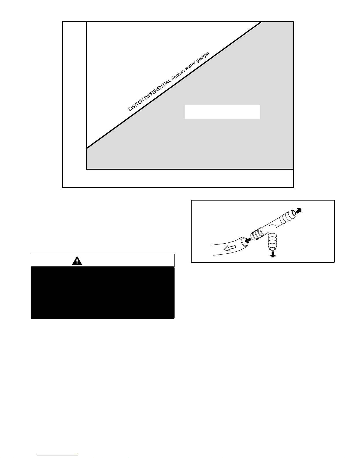
−1.2
CHART REPESENTS NORMAL OPERATING
CHARACTERISTICS OF THE PRESSURE SWITCH ONLY
AND SHOULD NOT BE USED FOR TROUBLSHOOTING
−1.0
−0.8
−0.6
−0.4
−0.2
COMBUSTION AIR BLOWER STATIC PRESSURE
DIFFERENTIAL SWITCH CLOSED
0
−0.4 −0.6 −0.8 −1.2
BURNER BOX STATIC PRESSURE
FIGURE 19
Temporarily jumpering the pressure switch when trouble
shooting will determine if the pressure switch and furnace
are operating properly. However, this may not indicate if the
sealed combustion system is operating properly. If the unit
cannot attain the required inches differential (see table 12)
, the unit will not operate. Be sure to remove jumper when
finished. See Warning this page.
DIFFERENTIAL SWITCH OPEN
(Furnace will not operate)
−1.0−0.20
TEE AND 1/4"i.d. RUBBER HOSE FIELD PROVIDED
USED FOR MEASURING PRESSURE
ACROSS BURNER BOX AND COM
BUSTION AIR BLOWER
TO PRESSURE
SWITCH
TO PRESSURE
SENSING HOSE
WARNING
Safety Hazard. Turn off gas supply before jump
ering switch or testing switch differential. If
switch is operating properly and sealed com
bustion system is operating improperly, a po
tentially lethal situation will be created when
switch is bypassed. DO NOT ALLOW UNIT TO
OPERATE WITH SAFETY SYSTEMS BYPASSED.
Checks of pressure differential can be made as an aid in trou
bleshooting. It is important to remember that the switch must
see the required differential in order for the furnace to operate.
Lack of differential usually indicates problems in the intake or
exhaust piping but may indicate problems in the heat ex
changer, condenser coil, header boxes, combustion blower or
other components. Generally, if both readings are closer to
zero (figure 19) the unit may have a restricted flue outlet or oth
er problem. If both readings are farther from zero (figure 19)
the unit may have a restricted flue inlet or other problem.
Measuring pressure differential
The differential pressure is the difference in pressure mea
sured on either side of the pressure switch:
1 − Remove thermostat demand and allow to cycle off.
2 − Disconnect hose from left side of pressure switch and
install Tee as shown in figure 20.
TO DRAFT GAUGE
FIGURE 20
3 − Install draft gauge to open end of Tee.
4 − Operate unit and observe draft gauge reading. Read
ings will change as heat exchanger warms.
a. Take one reading immediately after startup.
b. Take a second reading after unit has reached steady
state (approximately 5 minutes).
5 − Remove thermostat demand and allow to cycle off.
6 − Remove draft gauge and Tee. Reinstall combustion air
sensing hose to left side of pressure switch.
7 − Disconnect hose from right side of pressure switch and
install Tee as shown in figure 20.
8 − Install draft gauge to open end of Tee.
9 − Operate unit and observe draft gauge reading. Read
ings will change as heat exchanger warms.
a. Take one reading immediately after startup.
b. Take a second reading after unit has reached steady
state (approximately 5 minutes). Both readings should
fall above the line shown in figure 19.
10− Compare readings to figure 19. Be sure to compare
only like readings (compare startup reading to startup
reading, then compare steady state reading to steady
state reading). Subtract the absolute steady state
readings from one another. This will be the pressure
differential. In order for the furnace to operate, the
larger negative must always be on the combustion
Page 17
 Loading...