

INSTALLATION
LENNOX
_2001 Lennox Industt]e-_ _nc
Dallas Texas USA
RETAIN THESE INSTRUCTIONS
FOR FUTURE REFERENCE
INSTRUCTIONS
G32Q SERIES UNITS
GAS UNITS
504,488M _[_2ech nical
11/2001 blications
Supersedes504,382M LithoU.S.A.
ITahi6of_ __te:nts i ::
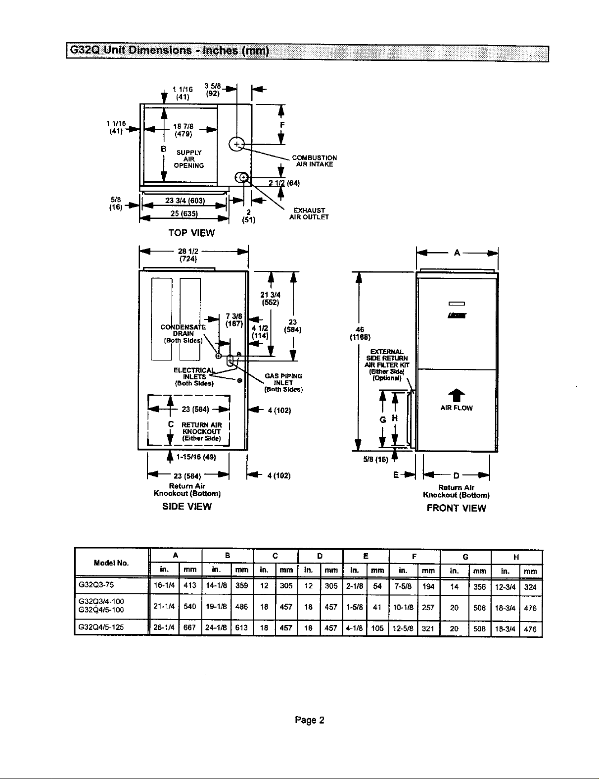
UnitDimensions ................................ 2
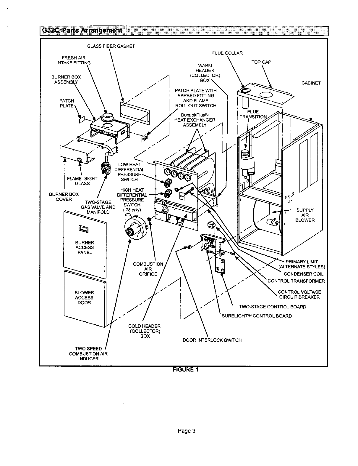
G32Q Parts Arrangement ....................... 3
Requirements.................................. 4
General ....................................... 5
Installation - Setting Equipment .................. 5
Return Air Opening Guidelines ................... 5
Filters & Optional Filter Assembly ................. 6
Duct System ................................... 7
Pipe & Fittings Specifications .................... 7
Vent Piping L_uidelines.......................... 8
Joint Cementing Procedure ...................... 8
Venting Practices ............................... 9
Gas Piping ................................... 15
Electrical ..................................... 16
Unit Start-Up ................................. 21
Heating Sequence of Operation ................. 22
Blower Operation .............................. 22
Gas Pressure Adjustment ...................... 22
High Altitude Information ....................... 23
Other Unit Adjustments ........................ 23
Service ...................................... 24
Repair Parts .................................. 27
Troubleshooting ............................... 27
Start-Up & Performance Checklist . 32
-AWARNING
WHAT TO DO IF YOU SMELL GAS:
Do not store or use gasoline or other
flammable vapors and liquids in the vi-
cinity of this or any other appliance.
Installation and service must be per-
formed by a qualified installer, service
agency or the gas supplier,
11101 504,488M
• Do not by to light any appliance.
• Extinguish any open flames.
• Do not touch any electrical switch; do not use
any phone in your building.
• Immediately call your gas supplier from a
neighbor's phone. Follow the gas supplier's
instructions.
• If you cannot reach your gas supplier, call the
fire department.
IIIIIIIIIlHIIIIIIHIIIIIIIIIIIIIIIIII Pagol IIIIHIIIIIIIIllllIIHHItllUlIIHII
1 1116
(41)
_8
(16)'-IP
1 1116 3 5/8
,o-oI
• v 151 ) AIR OUTLET
TOP VIEW
"ql'-- 28 1/2
I I
(724)
T
ELECTRICA
INLETS_
{BothSides)
91- 4(102)
L _____(EitherSide) J
Lt:;:"ZtJ
Return Air
Knockout (Bottom)
SIDE VIEW
21 3/4
(552)
GAS PIPING
INLET
(Both Sides)
4 (I02) E-IP
T
46
(1168)
EXTERNAL
SIDE RETURN
/_R FIL'I1ERK]T
(Either Side
O_onal ,
,lira A_
I I
m
t
AIR FLOW
Return Air
Knockout (Bottom)
FRONT VIEW
Model No.
G32Q3-75 16-1/4 413 14.1/8 359 12 305 12 305 2-118 54 7-5/8 194 14 356 12-3/4 324
G32Q3/4-100
G32(_4/5-100 21-1/4 540 19-1/8 486 18 457 18 457 1-5/8 41 10-1/8 257 20 508 18-3/4 476
G32Q4/5-125 26-1/4 667 24-1/8 613 18 457 18 457 4-1/8 105 12-5/8 321 20 508 18-3/4 476
A B C D E F G H
in. I mm in. mm in. mm In, mm In. mm in. mm in. mm in, mm
Page 2
FRESH AIR
INTAKE FITTING
BURNERBOX
ASSEMBLY
PATCH
GLASS FIBER GASKET
HEADER
. BOX
/
_I (COLLECTORTH__
/ PATCH PLATE WITH
l BARBED FITTING
ROLL-OUT SWITCH
HEAT EXCHANGER
WARM
AND FLAME
DuralokPlus TM
ASSEMBLY
FLUE COLLAR
TOP CAP
CABINET
FLUE
FLAME SIGHT p swrrcH
GLASS
BURNER BOX /
COVER ]3NO-STAGE PRESSURE
GAS VALVE AND SWITCH
BURNER
ACCESS
PANEL
BLOWER
ACCESS
DOOR
TWO-SPEED
COMBUSTION AIR
INDUCER
/
MANIFOLD (-75 only)
RESSURE-.
HIGH HEAT
AIR
ORIFICE
z-/"
COLD HEADER
(COLLECTOR)
BOX
DOOR INTERLOCK SWITCH
4. SUPPLY
S/" _ BLOWER
CONDENSERCOIL
CONTROL TRANSFORMER
CONTROL VOLTAGE
CIRCUIT BREAKER
TWO-STAGE CONTROL BOARD
LBOARD
AIR
FIGURE 1
Page 3
Lennox G32Q units are CSA International certified to
ANSI Z21.47 and CSA 2.3 standards.
In the USA, installation of Lennox gas central furnaces
must conform with local building codes. In the absence of
local codes, units must be installed according to the cur-
rent National Fuel Gas Code (ANSI-Z223.1) in the United
States. The National Fuel Gas Code is available from the
following address:
Amedcan National Standards Institute, Inc.
11 West 42rid Street
New York, NY 10036
In Canada, installation must conform with current Nation-
al Standard of Canada CAN/CGA-B149.1 "Installation
Code for Natural Gas Burning Appliances and Equip-
ment" and CAN/CGA-B149.2 "Installation Code for Pro-
pane Gas Burning Appliances and Equipment," local
plumbing or waste water codes and other applicable local
codes.
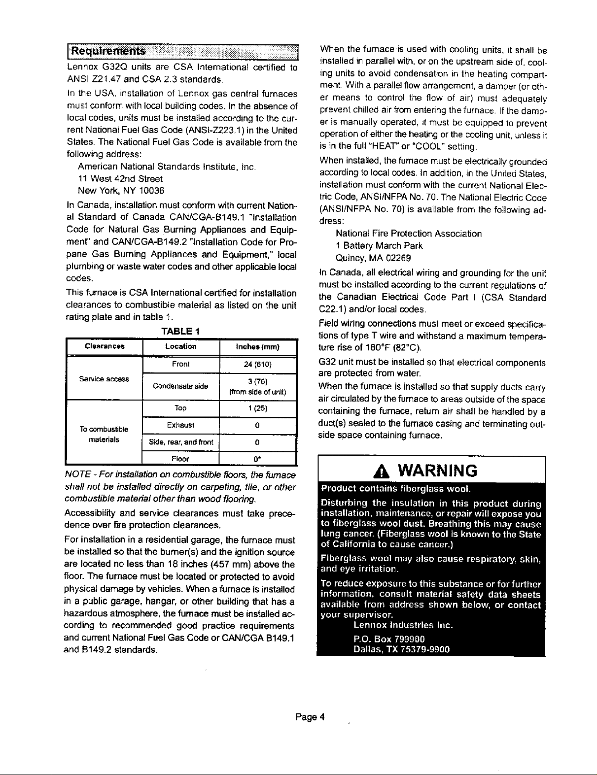
This furnace is CSA International certified for installation
clearances to combustible matedal as listed on the unit
rating plate and in table 1.
TABLE 1
Clearances Location
Front
Service access
To combustible
materials Side, rear,and front
Condensate side
Top
Exhaust
Floor
Inches(mrn)
24 (610)
3(76)
(fromsideofunit)
1(2s)
0
0
0*
NOTE -For installation on combustiblefleers, the furnace
shaft not be installed directly on carpeting, tile, or other
combustible material other than wood flooring.
Accessibility and service clearances must take prece-
dence over fire protectionclearances.
For installation in a residential garage, the furnace must
be installed so that the burner(s) and the ignition source
are located no less than 18 inches(457 mm) above the
floor. The furnace must be located or protected to avoid
physical damage by vehicles. When e furnace is installed
in a public garage, hangar, or other building that has a
hazardous atmosphere,the fumace mustbe installed ac-
cording to recommended good practice requirements
and current National Fuel Gas Code or CAN/CGA B149.1
and B149.2 standards.
When the furnace is used with cooling units, it shall be
installed in parallel with, or on the upstream side of. cool-
ing units to avoid condensation in the heating compart-
ment. With a parallel flow arrangement, a damper (or oth-
er means to control the flow of air) must adequately
prevent chilled air from entering the furnace. If the damp-
er is manually operated, it must be equipped to prevent
operation of either the heating or the cooling unit, unless it
is in the full =HEAT" or "COOL" setting.
When installed, the furnace must be electrically grounded
according to local codes. In addition, in the United States,
installation must conform with the current National Elec-
tric Code, ANSI/NFPA No. 70. The National Electric Code
(ANSI/NFPA No. 70) is available from the following ad-
dress:
National Fire Protection Association
1 Battery March Park
Quincy, MA 02269
In Canada, all electrical wiring and grounding for the unit
must be installed according to the current regulations of
the Canadian Electrical Code Part I (CSA Standard
C22.1 ) and/or local codes.
Field widng connections must meet or exceed specifica-
tions of type T wire and withstand a maximum tempera-
ture dee of 180°F (82°C).
G32 unit must be installed so that electrical components
are protected from water.
When the furnace is installed so that supply ducts carry
air circulated by the furnace to areas outside of the space
containing the furnace, return air shall be handled by a
duct(s) sealed to the furnace casing and terminating out-
side space containing furnace.
A WARNING
Page 4
NOTE - G32 senes units must not be used as a construc-
tion heater dunng any phase of construction. Very low re.
turn air temperatures, harmful vapors and misplacement
of the filters will damage the unit and lower its efficiency.
The G32Q is an upflow gas furnace. A changeover kit
is necessary if the furnace is to be used with L.P. gas,
These instructions are intended as a general guide and
do not supersede Focal codes in any way. Consult authori-
ties having jurisdiction before installation.
Shipping and Packing List
1 - Assembled G32 furnace
1 - 3 inch x 2 inch vent transition piece (-100, -125
units only)
1 - Bag assembly containing:
1 - Electrical make-up box
1 - Widng harness
1 - Snap bushing
2 - Filter clips
1 - Condensate plug
1 - Condensate drain adapter
1 - Brown accessory wire
1 - Green ground wire
4 - Wire nuts
2 - Star washers and screws
8 - Self-tapping screws
1 - Grounding label
1 - Wire tie
3 - Thread-forming screws
Shipping Damage
Check equipment for shipping damage. If you find any
damage, immediately contact the last carrier.
I Insta!iatton' Setttng Equipment
Select a location that allows for required clearances listed
on the unit rating plate. Also consider gas supply connec-
tions, electrical supply, vent connection and installation
and service clearances [24 inches (610 mm) at unit front].
The furnace must be level.
NOTE - 1/3 and 1/2 hp blower motors are equipped with
either four flexible mounting legs or three flexible legs and
one ngid leg. The ngid leg is equipped with a shipping bolt
and a flat white plastic washer (rather than the rubber
mounting grommet used with a flexible mounting leg).
This shipping bolt and flat washer must be removed be-
fore the furnace is put into operation. Once the sh_pping
bolt and washer are removed, the rigid leg will not touch
the blower housing.
_ CAUTION
[ . WARNING I
WARNING
WARNING
Returnaircan be brought ineithersideor atthe bottomof
the unit.Scdbelinesshowthe outlineofeach sideandthe
bottom return air opening.
Page 5

Bottom Return Air Applications
If return air is to terminate through the floor under the fur-
nace, a direct, airtight and sealed connection must be
made to the bottom of the furnace,
1 - Cut opening in floor or platform. Using knockouts
provided, cut bottom of base panel. See figure 2.
KNOCKOUT PATTERN FOR BOTTOM
RETURN AIR APPLICATION
,v vd
iV Vd
_
Bottom Return Air Applications
1 - Remove blower access panel.
2- Install filter clips, provided with unit, by slipping
folded section of clip on edge of bottom opening. See
figure 4.
3 - Place filter in bottom of blower compartment beneath
rear filter clip. Press down on filter sides. Filter clips
flex allowing filter to snap into place.
4 - To remove filter, press clip and pull filter up and out.
BOTTOM RETURN FILTER INSTALLATION
REAR FILT R CLIP
URNACE
BACK
FIGURE 2
2 - Bend a flange on return air plenum and lower into
floor or platform opening, See figure 3.
3 - Position unit over return air opening. Seal unit air
tight with return air plenum•
BOTTOM RETURN AIR APPLICATION
G32 UNIT
RETURN AIR
PLENUM
PROPERLY
SIZED FLOOR
OPENING
FIGURE 3
NOTE - Be cerefu/ not to damage insulation. Check for
tight seal,
Side Return Air Applications
For installationswhere the return air is taken fl'oma retum
airdrop,unitmay be installed with mtum airentl_ through
eitherthe left or rightside of thefurnace.
For sidereturnair applications,cutfurnace cabinetat the
dimensionsgivenon page 2. Embossedcomers are pro-
vided onbothcabinet sidesfor returnairopeninglocation.
i_ii_!'2'i:i:i_:"i:ii:i:i:;'i:!:11:71:i:7i:i:7!:;:i!:ii:ii;ii'i:ii'i:_;:""_'::<"_i:":i_i_ii,ii_::i:!Ti:i;_;:7:%TiJ;:::tT;;:::7:7
This unitis not equippedwith a filteror rack.A field-pro-
videdhigh-velocityfilteris requiredforthe unitto operate
properly.A filter must be in place any time the unit is
operating. The unit does include filter clips for instal-
lation of a field-provided, internally installed filter.
See figure 4.
SIDE _
FURNACE FURNACE
FIGURE 4
Side Return Air Applications
Filter racks are available fromLennoxfor side returnair
applications.See figures5 and 6.
NOTE - Thefilter doormay be shipped in therack behind
thefilter./fnecessa_ remove the filter, retrieve the door
and continuewiththe installationof the rack.
1 - Align filterrack opening withthe inside edge of the
side return opening. Bottom of rack should be
approximately1 inch(25 mm) fromthe bottom and 3
inches(76 mm) from the frontof the unit.
2 - Screw filter rack intoplacewiththe eightselfddll,self
tap screws provided.See figure 5.
3 - Push filter door pinsthrough the two holes in filter
doorfrom the insideof the u-channel. See figure 6.
SIDE RETURN FILTER INSTALLATION
in.(turn)
BLOWER DECK _=
RETURN AIR
RETURN 12 in. (305) for
AIR 14 in. 13561Filter
OPENING t8 In. (437) for
20 in, (508) Filter
1-13/t6in.
cAa,NETBASEI; .OM,I
PLENUM SIZE
12-314 In X 23-1/2 In (324 X
597) for 14 In (356) Filter
18-3/4 In. x 23-1/2 In,
(476 x 507)
for 20 In. 1508) Filter
(34)
FIGURE 5
Page 6
FILTER DOOR ASSEMBLY
FILTER DO0_ _
PIN _T_ TAB
FILTER DOOR I I I _'l]l
FILTER
FIGURE 6
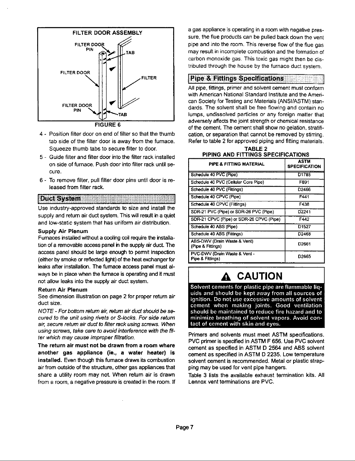
4 - Positionfilter door on end offilter so that the thumb
tab side of the filter door is away from the furnace.
Squeeze thumb tabs to secure filter to door.
5 - Guide filter and filter door into the filter rack installed
on side of furnace. Push door into filter rack until se-
cure.
6 - To remove filter,pull filterdoor pins untildoor is re-
leased from filter rack,
Use industry-approved standards to size and install the
supply and return air duct system. This will resultin a quiet
and low-static system that has uniform air distribution.
Supply Air Plenum
Furnaces installedwithout acoolingcoilrequirethe installa-
tion of aremovable access panel inthe supplyair ducL The
access panel should be large enough to permit inspection
(either by smoke or reflectedlight) ofthe heatexchanger for
leaksafter installation. The furnace access panel must al-
ways be in placewhen the furnace is operatingand it must
not allow leaks into the supply air duct system.
Return Air Plenum
See dimensionillustrationon page 2 for properreturnair
duct size.
NOTE - For bottomreturn air, returnairductshouldbe se-
curedto the unit usingrivets or Sqocks. For side return
air,secure return airduct to filterrackusingscrews. When
using screws, take care to avoid interference with the fil-
ter which may cause improper filtration.
The return air must not be drawn from a room where
another gas appliance (ie,, a water heater) is
installed. Even thoughthisfurnace draws its combustion
air from outside of the structure, other gas appliances that
share a utility room may not. When retum air is drawn
from a room, a negative pressure is created in the room. If
a gas appliance is operating in a room with negative pres-
sure, the flueproducts can be pulled back down the vent
pipe and into the room. This reverse flow of the flue gas
may result in incomplete combustion and the formation of
carbon monoxide gas. This toxic gas might then be dis-
tributed through the house by the furnace duct system.
Pipe & _tttings S _¢ifi_ti_
J :::%:::::::::::::::: ::: : ::
All pipe,fittings,primerand solventcementmust conform
withAmericanNationalStandard Instituteand theAmeri-
can Society for Testingand Materials (ANSI/ASTM) stan-
dards. The solvent shall be free flowing and contain no
lumps, undissolved particles or any foreign matter that
adversely affectsthejoint strength or chemical resistance
of thecement. The cement shall show no gelation, stratifi-
cation, or separation that cannot be removed by stining.
Refer to table 2 for approved piping and fitting materials.
TABLE 2
PIPING AND FITTINGS SPECIFICATIONS
PIPE & FITrlNG MATERIAL SPECIFICATION
Schedule 40 PVC (Pipe) D1785
Schedule 40 PVC (CellularCore Pipe) F89t
Schedule 40 PVC (Fittings) D2466
Schedule40 CPVC (Pipe) F441
Schedule 40 CPVC (Fittings) F438
SDR-21 PVC (Pipe)or SDR-26 PVC (Pipe) D2241
SDR-21 CPVC (Pipe)or SDR-26 CPVC (Pipe) F442
Schedule 40 ABS (Pipe) D1527
Schedule 40 ABS (Fittings) D2468
ABS-DWV (Drain Waste & Vent)
(Pipe & Fittings) D2661
PVC-DWV (Drain Waste & Vent - D2665
Pipe & Fittings)
ASTM
A CAUTION
Primers and solventsmust meet ASTM specifications,
PVC pdrnerisspecifiedin ASTM F 656. UsePVC solvent
cement as specified in ASTM D 2564 and ABS solvent
cement as specified in ASTM D 2235. Low temperature
solvent cement is recommended. Metal or plastic strap-
ping may be used for vent pipe hangers.
Table 3 liststhe available exhaust termination kits. All
Lennox vent terminations are PVC.
]
Page 7
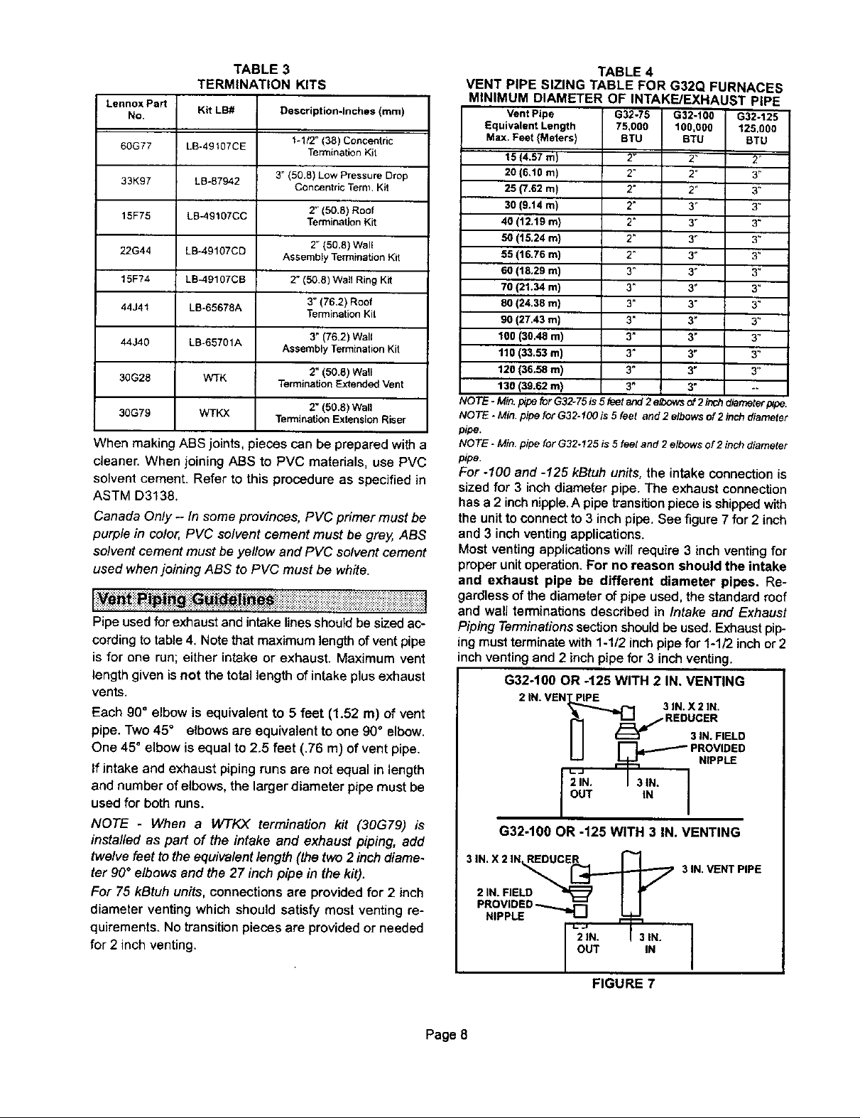
TABLE 3
TERMINATION KITS
Lennox Part
No.
60G77
33K97
15F75
22G44
15F74
44J41
44J40
30G28
30G79
Kit LB# Description*Inches (ram)
LB-49107CE
LB-87942
LB-49107CC
LB-49107CD
LB_9107CB
LB-65678A
LB-65701A
WTK
WTKX
1-1/2" (38) Concentric
Termination Kit
3" (50,8) Low Pressure Drop
Concentric Term Kit
2" (50,8) Roof
Termination Kit
2" (50.8) Well
Assembly Termination Kit
2" (50.8) Walt Ring Kit
3" (76,2) Roof
Termination Kit
3" (76.2) Wall
Assembly TerminationKit
2" (50.8) Wall
TerminationExtendedVent
2" (50.6) Wall
TerminationExtensionRiser
When making ABSjoints, pieces can be prepared with a
cleaner. When joining ABS to PVC matedals, use PVC
solvent cement. Refer to this procedure as specified in
ASTM D3138.
Canada Only - In some provinces, PVC primer must be
purple in color, PVC solvent cement must be grey, ABS
solvent cement must be yellow and PVC solvent cement
used when joining ABS to PVC must be white.
[
:: ::,::.:_::: : :: ::.::..: :.:::::::::: .::::::.:::::::::::::::::.:::::::::::::::::;:. :::_:::::::::::::::::::::::::::::::::::::::::::::::::::::::::::::::::::::::::::::::::::::::::::: :: :: ::.:]
Pipe used for exhaust and intake lines should be sized ac-
cording to table 4. Note that maximum lengthof vent pipe
is for one run; either intake or exhaust. Maximum vent
length given isnot the total length of intake plus exhaust
vents.
Each 90° elbow is equivalent to 5 feet (1.52 m) of vent
pipe. Two 45° elbows are equivalent to one 90° elbow.
One 45° elbow is equal to 2.5 feet (.76 m) of vent pipe.
If intake and exhaust piping runs are not equal in length
and number of elbows, the larger diameter pipe must be
used for both runs.
NOTE - When a WTKX terminaUon kit (30G79) is
installed as part of the intake and exhaust piping, add
twelve feet to the equivalent length (the two 2 inch diame-
ter 90° elbows end the 27 inch pipe in the kit).
For 75 kBtuh units, connections are provided for 2 inch
diameter venting which should satisfy most venting re-
quirements. No transition piecesare provided or needed
for 2 inch venting.
TABLE 4
VENT PIPE SIZING TABLE FOR G32Q FURNACES
MINIMUM DIAMETER OF INTAKE/EXHAUST PIPE
Vent Pipe
Equivalent Length
Max. Feet (Meters)
15 (4.57 m)
20 (6,10 m)
25 (7.62 m)
30 (9.14 m)
40 (12.19 m)
50 (I 5.24 m)
55 (16.76 m)
60 (18,29 m)
70 (21,34 rn)
80 (24.38 m)
90 (27.43 m)
100 (30.48 m)
110 (33,53 m)
120 (36.58 m)
130 (39.62 m)
NOTE - Min. pipeforG32-75 is 5feet and 2elbowsof 2inchdmmeterp_pe.
NOTE - Min. pipe for G32-100 is 5feet end 2 elbowsof 2 inch diameter
pipe,
NOTE - Min. pipe for G32-125 is 5 feet and 2 e/bows of 2 inchdiameter
pipe.
G32-76 G32-100 G32-125
75,000 100,000 125.000
BTU BTU BTU
2" 2" 2'
2" 2" 3"
2" 2" 3"
2" 3" 3_
2" 3" 3"
2" 3" 3"
2" 3" 3"
3" 3" 3"
3" 3" 3"
3" 3" 3"
3" 3" 3"
3" 3" 3"
3" 3" 3"
3" 3" 3"
3" 3" --
For -100 and -125 kBtuhunits,the intakeconnectionis
sized for 3 inch diameter pipe. The exhaustconnection
has a 2 inchnipple,A pipetransitionpieceis shippedwith
the unitto connectto 3 inchpipe. See figure7 for2 inch
and 3 inchventingapplications.
Most venting applicationswillrequire 3 inchventingfor
properunitoperation.For no reason should the intake
and exhaust pipe be different diameter pipes. Re-
gardlessofthe diameterofpipe used, the standardroof
l
and wail terminationsdescribed in Intake and Exhaust
Piping Terminations sectionshouldbe used.Exhaustpip-
ingmust terminatewith 1-1/2 inchpipefor 1-1/2 inchor 2
inchventingand 2 inch pipe for 3 inchventing.
G32-100 OR -125 WITH 2 IN. VENTING
2 IN. VEN_] 3RIIENI_X C2EIN,
2IN. I 3IN.
OUT N
G32-100 OR -125 WITH 3 IN. VENTING
3 IN. VENT PiPE
L_I
NIPPLE ,..,
OUT IN
FIGURE 7
I
Page 8
All cementing of joints should be done according to the
specifications outlined in ASTM D 2855.
1 - Measure and cut vent pipe to desired length.
2 - Debur and chamfer end of pipe, removingany ddges
or rough edges. If end is notchamfered, edge of pipe
may remove cement fTomfitting socket and result in
a leaking joint.
3 - Clean and dry surfaces to be joined.
4 - Test fit joint and mark depth offitting on outside of
pipe.
5 - Uniformly applyliberal coatof PVC primer for PVC or
ABS cleaner for ABS to inside socket surface of fit-
ting and male end of pipe to depth of fitting socket.
6 - Promptly apply solvent cement to end of pipeand in-
side socket surface of fitting. Cement should beap-
plied lightly but uniformly to inside of socket. Take
care to keep excess cement out of socket. Apply
second coat to end of pipe.
NOTE - Time is critical at this stage. Do not allow
pnmer to dry before applying cement.
7 - Immediately after applying last coat of cement to
pipe, and while both inside socketsurface and end of
pipe are wet with cement, forcefully insert endof pipe
intosocket until it bottoms out. Turn pipe 1/4turn dur-
ing assembly (but not after pipe is fully inserted) to
distribute cement evenly.
NOTE - Assembly should be completed within 20
seconds after last application of cement. Hammer
blows should not be used when inse_ng pipe.
8 - After assembly, wipe excess cement from pipe at
end of fitting socket.A properlymadejointwillshowa
bead around itsentireperimeter. Anygaps may indi-
cate a defective assembly due to insufficientsol-
vent.
9 - Handle joints carefully untilcompletelyset.
Iventing ractl es
The thickness of construction through which vent!air in-
take pipes may be installed is a minimum of 3inches (76
mm) and a maximum of 24 inches (610 mm). If a G32 fur-
nace replaces a furnace which was commonly vented
with another gas appliance, the size of the existing vent
pipe for that gas appliance must be checked. Without the
heat of the originalfurnace flue products, the existing vent
pipe is probably oversized for the single water heater or
other appliance. The vent should be checked for proper
draw with the remaining appliance,
Intake Piping
1 - Cement intakepipinginslip connectorlocated at top
of unit.
2 - Route pipingto outside of structure.Continue with
installationfollowing instructionsgiven in exhaust
and intakepipingterminationsection.
WARNING
Exhaust Piping
1- Cemente_(haustpipthgintofluecollarsocketloceted
on the left side of the top cap.
2 - All horizontalruns ofexhaust pipe mustslopeback
towardthe unit.A minimumof 1/4 inch(6 ram) drop
for each 12inches(305 mm) ofhorizontalrunisman-
datory fordrainage. Horizontal runs ofexhaust pip*
ing mustbe supported every 5 feet (1.52 m) using
hangers.
Page 9
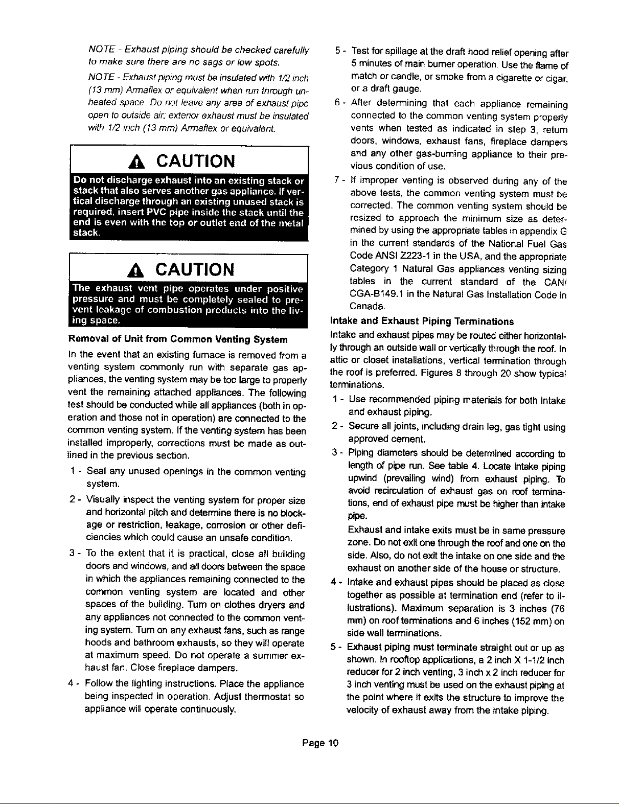
NOTE - Exhaust piping should be checked carefully
to make sure there are no sags or low spots.
NOTE - Exhaust piping must be Insulated wffh 1/2 inch
(13 ram) Armaflex or equivalent when nJn through un-
heated space. Do not leave any area of exhaust pipe
open to outside air. extenor exhaust must be insulated
wrth 1/2 inch (13 ram) Armaflex or equivalent.
{
Zl, CAUTION
CAUTION
Removal of Unit from Common Venting System
In the event thatan existing furnace is removed from a
venting system commonly run with separate gas ap-
pliances, the venting system may be too largeto property
vent the remaining attached appliances. The following
test should be conducted while all appliances (beth inop-
eration and those not in operation) are connected to the
common venting system.If the venting system has been
installed improperly, corrections must be made as out-
lined in the previous section.
1 - Seal any unused openings in the common venting
system.
2 - Visually inspect the venting system for proper size
and horizontal pitchand determinethere is noblock-
age or restdction,leakage, corrosionor other defi-
ciencieswhich couldcause an unsafe condition.
3 - To the extent that it is practical, close all building
doors andwindows,and alldoorsbetweenthe space
in which the appliancesremainingconnectedto the
common venting system are located and other
spaces of the building. Turn on clothes dryers and
any appliancesnot connectedto the common vent-
ing system. Turn on any exhaust fans, suchas range
hoods and bathroom exhausts, so they will operate
at maximum speed. Do not operate a summer ex-
haust fan. Close fireplace dampers.
4 - Follow the lightinginstructions. Place the appliance
being inspected in operation. Adjust thermostat so
appliance will operate continuously.
5 - Testfor spillage at thedraft hood relief openingafter
5 minutes of main burner operation. Usethe flame of
match or candle, or smoke from a cigarette or cigar,
or a draftgauge.
6- After determining that each appliance remaining
connected to the common venting system properly
vents when tested as indicated in step 3, return
doors, windows, exhaust fans, fireplace dampers
and any other gas-burning appliance to their pre-
I
vious condition of use.
7 - If improper venting is observed dudng any of the
above tests, the common venting system must be
corrected. The common venting system shouldbe
resized to approach the minimum size as deter-
mined by using the appropriate tables in appendixG
in the current standards of the National Fuel Gas
Code ANSI Z223-1 in the USA, and the appropriate
Category 1 Natural Gas appliances venting sizing
tables in the current standard of the CAN/
CGA-B149.1 in the Natural Gas InstalLationCode in
Canada.
Intake and Exhaust Piping Terminations
Intake and exhaustpipesmay be routedeitherhorizontal-
lythrough an outsidewallor verticallythroughthe roof.In
attic or closet instaUations,verticalterminationthrough
the roofis preferred. Figures 8 through20 show typical
terminations.
1 - Use recommendedpiping materials for both intake
and exhaust piping.
2 - Secure all joints,includingdrain leg, gas tightusing
approvedcement.
3 - Pipingdiametersshouldbe determinedaccordingto
length of pipe run.See table 4. Locate intakepiping
upwind (prevailing wind) from exhaust piping. To
avoid recirculation of exhaust gas on roof termina-
tions, end of exhaust pipe must be higher than intake
pipe.
Exhaust and intake exits must be in same pressure
zone. Do not exit one through the roof and oneon the
side. Also, do not exittheintake on one sideand the
exhaust on another side of the house or structure.
4 - intake andexhaust pipes should be placed as close
together as possible at termination end (refer to il-
lustrations). Maximum separation is 3 inches (76
ram) on roof terminations and 6 inches (152 ram)on
sidewall terminations.
5 - Exhaustpipingmust terminate straightout or up as
shown, tn rooftopapplications,a 2 inchX 1-1/2 inch
reducer for 2 inch venting,3 inch x 2 inch reducerfor
3 inch venting must be used on the exhaust piping at
the point where it exits the structure to improve the
velocity of exhaust away from the intakepiping.
Page 10

On roof terminations, the intake piping should termi-
natestraight down using two 90° elbows.See figure 8.
NOTE - If winter design temperature is below 32°F (O°C),
exhaust piping must be insulated with 1/2 inch (13 mm)
Armaflex or equivalent when run through unheated
space. Do not leave any surface area of exhaust pipe
open to outside air," exterior exhaust pipe must be insu-
lated with 1/2 inch (13 ram) Armaflex or equivalent. In ex-
treme cold climate areas, 3/4 inch (19 mm) Armaflex or
equivalent is recommended. Insulation on outside runs of
exhaust pipe must be painted or wrapped to protect in-
sulation from deterioration.
NOTE - During extremely cold temperatures, below
approximately 20°F (6.67°C), units with long runs of vent
pipe through unconditioned space, even when insulated,
may form ice in the exhaust termination that prevents the
unit from operating properly. Longer run times of at least 5
minutes will alleviate most icing problems. Also, a heating
cable may be installed on exhaust piping and termination
to prevent freeze-ups. Heating cable installation kit is
available from Lennox. See Condensate Piping section
for part numbers.
NOTE - Care must be taken to avoid recirculation of ex-
haust back into intake pipe.
6 - On field-supplied terminations for side wall exits, ex-
haust piping should extend a maximum of 12 inches
(305 mm) beyond the outside wall. Intake piping
should be as short as possible. See figure 10.
Inches (ram) 3 x 2 (70 x 51) OR
12 (305) ABOVE SPACE
ACCUMULATION
AVERAGE SNOW
3 (76) OR UNCONDmONED
2 (5t) PVC ATTIC SPACE
PROVIDE SUPPORT
FOR INTAKE AND
F.XHAUST LINES
(15F'75)LB-49107CCfor2 (5t) Venting
(44341)LB-65678Afor 3 (76)Venting
IMAX.
2 x %1/2 (51 x 38)
PVC REDUCER
ROOFTERMINATIONKIT
FIGURE 8
1/2 (13) FOAM
INSULATION IN
UNCONDrrlONED
EXHAUST
INTAKE
TERMINATION
EXHAUST INTAKE
CONCENTRIC ROOFTOP TERMINATION
(60G77) LB-49107CE for G32-75 Units Only
(33K97) LB-87942 for G32-100 & -125 Units Only
12 (305) ABOVE
AVERAGE SNOW
ACCUMULATION
Inches (mm)
FIGURE 9
1/2 (13) ARMAFLEX
INSULATION IN
UNCONDITIONED SPACE
1/2 (13) ARMAFLEX t'
INSULATION
OUTSIDE j
WALL
Inches (ram)
(15J74) LB-49107CBfor2 (50,8! Venting
TOPVIEW
WALLRINGKIT
12 (305) MIN.
2 X 1-1/2
(51 X 38)
PV REDUCER
_ _ 'VC
I 6 (I 52)
MAXIMUM
_ 2 (_ I PVC
PLING
FIGURE 10
7-
On field-supplied terminations, a minimum separa-
tion distance between the end of the exhaust pipe
and the end of the intake pipe is 8 inches (203 mm).
8-
If intake and exhaust piping must be run up a side
wall to position above snow accumulation or other
obstructions, the piping must be supported every 3
feet (.91 m) as shown in figure 15.Refer to figures 13
and 14 for proper piping method. W'FKwall termina-
tion kit must be extended for use inthis application,
See figure 18 or use kit WTKX shown in figure 19.
When exhaust and intake piping must be run up an
outside wall, the exhaust piping is reduced to 1-1/2
inches (38 mm) after the final elbow. The intake pip-
ing may be equipped with a 90°elbow turndown. Us-
ing 90° turndown will add 5 feet (1.5m) to the equiva-
lent length of the pipe.
Page 11

1/2 (12.7) FOAM INSULATION
IN UNCONDITIONED SPACE
n
qlp
TOPVIEW
WALLTERMINATION
(22G44)LB-49107CDfor2 (50,8)Venting
(44J40)LB-65701Afor3 (76.2)Venting
FIGURE 11
TERMINATION
EXHAUST
INTAKE
Inches (ram)
CONCENTRIC WALL TERMINATION
(60G77) LB-49107CE for G32-75 Units Only
(331(97) LB-87942 for G32-t00 & -125 Units Only
FIGURE 12
Inches (mm)
OUTSIDEWALL
Optional Turndown
Shown
(Intake Onty)
EXHAUST
abovegrade,
courtyard areas or other recessed areas. Do not
position termination ends directly below roof eaves
or above a walkway. Since the G32 is a certified di-
rect vent, Category iV gas furnace, the location of
the termination is limited by local building codes. In
the absence of local codes, refer to the current Na-
tional Fuel Gas Code ANSI Z223-1 in USA, and cur-
rent standard CAN/CGA-B149.1 of the Natural Gas
Installation Instructions in Canada for details. The
termination should be at least 12 inches (305 mm)
from any opening through which flue products could
enter the building.
When horizontally vented, minimum clearance for
termination from electric meters, gas meters, regula-
tors and relief equipment is 4 feet (1.2 m) for US
installations. Refer to the current CAN/CGA-B149.1
for installations in Canada or with authorities having
local jurisdiction.
At vent termination, care must be taken to maintain
protective coatings over building materials (pro-
longed exposure to exhaust condensate can destroy
protective coatings). It is recommended that the ex-
haust outlet not be located within 6 feet (1.8 m) of a
condensing unit because the condensate can dam-
age the painted coating.
Inches(mm)
UNCONDITIONED
SPACE
OUTSIDE WALL
PROVIDE SUPPORT
FOR INTAKE AND /
EXHAUST UNES EVERY
3_(914)
1/2113) FOAM
INSULATION IN
UNCONOmONED
SPACE
(15F74)LE-49107CBfor2 In. (51)Venting
See v.ntlng table 4 for maglng_ venting lengths with this Irmr:l_mant.
SiDEVIEW
WALLRINGTERMINATION
12 (305) MIN for2 (51)
20(5oa)MAXfor3(76):
F
HI II t2(S_0)ASOVE
Ii2 (131FOAM
INSULATION
FIGURE 13
9 - Position terminationends so they are free from any
obstructions and abovethe level ofsnowaccumula-
tion (where applicable). Termination ends must be a
minimum of 12 inches (305 mm) above grade level.
Do not point into window wells, stairwells, alcoves,
10 - Suspend piping using hangers at a minimum ofevery
5 feet (1.52 m) for schedule 40 PVC and every 3 feet
(.91 m) for ABS-DWV, PVC-DWV, SDR-21 PVC,
and SDR-26 PVC piping. A suitable hanger can be
fabricated by using metal or plastic strapping or a
large wire tie.
11 - In areas where piping penetrates joists or interior
walls, hole must be large enough to allow clearance
on all sides of pipe as it passes through the center of
the hole.
12 - Isolate piping at the point where it exits the outside
wall or roof.
Page 12

Inches(turn) 1/2 (13) 3 x 2 {76 x 51) OR
3 (76) OR FOR OFFSET TERMINATION
2 (51) 90_ELBOW
Optional Turndown _ _ 2 (5t) 90" ELBOW
(Not Shown)
May Be Used on
Intake Only FRONT VIEW
FOAM 2 x 1.t/2 (61 x 36)
INSULATION REDUCER BUSHING LOCATION
3 (76) OR
WALL TERMINATION
(22G44) LB-49107CD for 2(51) Venting
(44J40) LB-65701A for 3(76) Venting
FIGURE 14
METALOR PLASTIC
STRAPPING
FIGURE 15
13 - When furnace is installed in a residence where unit is
shut down for an extended period of time, such as a
vacation home, make provisions for draining con-
densate collection trap and lines.
14 - Based on the recommendation of the manufacturer,
a multiplefurnace installation may use a group of up
to four termination kits WTK assembled together
horizontally, as shown in figure 17.
Front View _,_, "_'l/EXHAUST VENT
Front View EXHAUST
18M
i EXHAUST VENT
Side View_
Inches (ram) • INTAKE
VENT
OPTIONAL VENT TERMINATION FOR
MULTIPLE UNIT INSTALLATION
WALL TERMINATION KIT WTK
FIGURE 17
Front View
INTAKE
AIR
1127)..L
IZ
(3os)
5
COVER EXHAUST
EXHAUST
GRADE
//// EXHAARUS_ SideView
_--T_-- ----n
// (('-_-_-_" II
INTAKE
AIR
/ / @1 812031
/ / I_=_,,,I,,,=_l Inches (ram)
//,ii II r'--r
lJil,
12
VENT WITH
1/2(13)
FOAM
INSULATION
AIR
t 2 MIN
(30_)
Above Grade
1/2 (13) Foam
Insulation in
Unconditioned _ace F
Inches (mm) L_
VENT TERMINATIONS
WALL TERMINATION KIT 130G28) WTK
FIGURE t6
Side View
EXHAUST VEN_
INTAKE VENT
OUTSIDE WALL
Page 13
/ / Mn}mum
/ / ABO'_GPJmE
, GRADE
VENT TERMINATIONS
MODEL WTK WALL TERMINATION KIT (30G28)
EXTENDED VENT FOR GRADE CLEARANCE
FIGURE 18

Inches (mm)
Front View
9
I '10" VENT
= _ NOTE - Enclosed ex_us_ pipe _s
[
INTAKE foam insu_abon If in_al(ear_ ex-
VENT hsusl I_pes am reversed, sl=land
34
_,EXHAUST
insuleted w;th _F2 i,_Ch(13 ram)
r_move foam instJlat_ot_ and
vent mr=st be insulated
freezing of the condensate, which would block the drain-
line. Use an electric heat cable if you route the conden-
sate line through unconditioned areas.
A CAUTION
Ii teat)ply to OUmr vent Exhaust
Side View
EXTENSION RISER FOR GRADE CLEARANCE
4
USTVENT
o
iNTAKE
VENT
E
VENT TERMINATIONS
MODEL WTKX (30GT9)
FIGURE 19
G32Q VENTING IN EXISTING CHIMNEY
NOTE - Do not dischal_e exhaust gases dit ently into or vent stack.
II ventCal discharge through at, ex_6ng unused chimney or stack ts require<J,
i_sertpipingintgde chlm,'.eyurdilthepipeopenendIs abovetopof _y and
termimlte as iltusttstad. I. any extedor po(tlon of ¢ilrmney, the exhaust vent must
be insulated.An alternatemethodistoflitthechimneywithvetrmc.ulitoorequal
to take advantage of its acoustic and thermal properties,
FIGURE 20
Condensate Piping
This unit is designed for either right- or left-side exit of
condensate piping. Route the condensate drainiine only
within the conditioned space: this prevents possible
1 - Determine which side condensate will exit the unit.
2- Connect 1/2 inch (13 mm) plastic pipe plug (pro-
vided) in the unused end of the condensate trap.
Install plug so that it is sealed water tight yet able to
be removed. Do not permanently seal the connec-
tion. Teflon tape is recommended to seal joint. See
figure 21.
CONDENSATE ASSEMBLY
(Forleftor rightinstallation)
COLD
COMBUSTION AIR HEADER
INDUCER BRACKET BOX
ADAPTER
ELBOW
CONDENSATE TRAP
NIPPLE BOOTORCAP
ADAPTER
FIGURE 2t
3 - Use the providedcondensate drain adapter (3/4" x
1/2") and a field-providednipple to carry drainage
outside the cabinet. If a fieldsubstitute is needed, 1/2
inch CPVC x 1/2 inch MPT adapter and 1/2 inch
CPVC is acceptable for use.
4 - Glue nipple to the adapter using the procedures out-
lined in the "Joint Cementing Procedures" section.
The nipple/adapter assembly should be connected
in a non-permanentmanner and must be water tight.
Teflon tape is recommended to seal the joint.
For Right-Hand Side Condensate Exit:
Install the nipple/adapter assembly from the out-
side of the cabinet and insert the adapter intothe
threaded opening in the condensate trap.
For Left-Hand Side Condensate Exit:
Insertnipple/adapterassemblyfrom the left hand
side of the cabinet and through the combustion air
inducer mounting structure into the threaded
opening in the condensate trap.
5 - Connect field-supplied plumbing to nipple and route
to open drain. Plumbing should be vented to a point
higher than the condensing coil. See figure 22.
Page14

CONDENSATE PLUMBING
(Plumbing must be vented higher than coll.)
FIGURE 22
6- Connect condensate drain line (1/2 inch [13 mm]
SDR 11 plastic pipe or tubing)to condensate con-
nection on condensate trap assembly and route to
open drain. Condensate line must be sloped down-
ward away from drip legto drain. If the drain level is
above condensate outlet, use a condensate pump to
pump the condensate to the higher level. Conden-
sate drain line should be routed within the condi-
tioned space to avoid freezing of condensate and
blockage of drain line. If this is not possible,a heat
cable kit may be used on the condensate line. Heat-
ing cable kit is available from Lennox in various
lengths; 6 feet (1.8 m) - kit no. 18K48; 24 feet (7.3 m)
- kit no. 18K49; and 50 feet (15.2 m) - kit no. 18K50.
3 - The gas piping must not run in or through air ducts,
clothes chutes, gas vents or chimneys, dumb wait-
ers orelevator shafts. Centergas line through piping
hole. Gas line should not touch side of unit. When
left-hand gas plumbing is required, gas line should
be installed in the lower half of knockout so that pip-
ing will clear combustion air inducer. See figure 24.
4 - The piping should be sloped 1/4inch (6.4mm) per 15
feet (4.57 m) upward toward the meter from the fur-
nace. The piping must be supported at properinter-
vals [every 8to 10feet (2.44 to 3.01 m) using suitable
hangers or straps. A drip leg should be installed in
vertical pipe runs to the unit.
5 - Some local codesmay require installationof a manu-
al main shut-off valve and union (furnished by the in-
staller) external to the unit. Union must be of the
groundjointtype,
II
CAP-_D-I_I U
FIGURE 23
NOTE - Installa 1/8inch NPTplugged tapin the field pip
ing upstream ofthe gas supplyconnection to the unit.The
tap must be accessible for test gauge connection. See
figure 24.
LEFT SIDE PIPING
MANUAL MAIN
SHUT-OFF
VALVE
1 - Gas piping may be muted into the unitthrough either
the left- or right-hand side. Supply piping enters into
the gas valve from the bottom of the valve asshown
in figure 24.
2- When connecting the gas supply, factors such as
length of run, number of fittings and furnace rating
must be considered to avoid excessive pressure
drop. Table 5 lists recommended pipe sizes for typi-
cal applications.
NOTE - Use two wrenches when connecting gas pip-
ing to avoid transferring torque to the manifold.
1/8in. NPT
PLUGGED
TAP
GAS VALVE
.... --I, RIGHT SIDE PIPING
_(.=.___=.-,_t_ (STANDARD)
118In. NPT
PLUGGED
..........................j,AP
GAS VALVE
FIGURE 24
Page 15

GAS PIPE CAPACITY - ft.3/hr Im31hrl
Nominal
Iron Pipe Size
-InchesImm)
t/4
(635)
3/8
(6,53)
(127)
314
(19.05)
1
(254)
1-1/4
(31.75)
Io1/2
(381)
2
(5O.8)
2-112
(83.5)
3
(76.2)
4
(101.6)
NOTE - Capacity j
Internal Length of Pipe-Feet (m)
Diameter 10 20 30 40 50 60 70 80 90 100
.InchesImm) (3.048) (6.096) (9.144) (12.192) 115.2401 (18.288) (21.336) (24.384) (27.432 (30.480)
364 43 29 24 29 18 18 15 14 19 12
(9 246) (1 13) (.82) (68) (.57) (81) (45) ( 401 (40} (3?) (.34)
493 95 65 52 45 40 36 33 31 29 27
(12.5221 (269) (1.84) (1 47) (127) (113) (1.02) (73) (88) (.82) (75)
622 175 120 97 82 73 66 61 57 53 50
(17.799) (496) (340) (2.75) (232) (2.07) (1.87) (173) (101) (1.50) (142)
.824 360 250 200 176 161 138 125 118 110 103
(20.930) (10.19) {706) (566) (4.81) (4.28) (3.91) (3 54) (3.34) (3 11) (292)
1049 680 468 379 320 288 260 240 220 208 !95
(26.645) (19,25) (13.17) (10,62) (9,06) (807) (7.36) (6 90) (6.23) (580) (6.62)
1.380 1400 960 770 660 580 630 490 460 430 400
(35.052) (39.64) (26.90) (21.80) (18,69) (1642) (15.01) (13.67) (13.031 (1218) (11.33)
1.610 21 O0 466 1180 990 900 810 750 690 650 620
(40.894) (59.46) (41.34) (3341) (2803) (2548) (22.94) (2124) (19.54) (1841) (17,56)
2.0_7 3950 2750 2200 1906 1680 1520 1400 1300 1220 1150
(52.502) (111.85) (77,87) (62.30) (5380) (47.57) (43.041 (3964) (36.81) (34.58) (32.56)
2469 6300 4350 9520 3000 2650 2400 2250 2050 1950 1880
(67 713) (17839) (12317) (9967) (84.95) (75.04) (67.96) (63.71) (58,05) (55.22) (52.38)
3068 11000 7700 6250 5300 4750 4300 3900 3700 3450 3250
(77.927) (31148) (218.03) (17698) (150.07) (134.50) (121,76) (110.43) (104.77) (97,69) (92.03)
4 026 23000 15800 12800 10900 9700 8800 St00 7500 7200 6700
(102.260) (651.27) (447.39) (362 44) (308.64) (274.67) (249.t8) (229.99) (212.37) (203.88) (189.72)
'iven in cubsc feet (m 3) o f gas per hour and based on O.60 specific gravity gas.
Leak Check
After gas piping is completed, carefully check all piping
connections (factory- and field-installed) for gas leaks.
Use a leak detecting solution or other preferred means.
CAUTION
TABLE 5
Figure 28 shows thermostat designations for identifica-
tion purposes. Refer to figure 29 for control box arra nge-
ment, figure 30 for adetail of the Surelight _integrated
control, figure 32 for point-to-point field wiring and figure
33 for schematic wiring diagram and troubleshooting,
ELECTROSTATIC DISCHARGE (ESD)
Precautions and Procedures
A, IMPORTANT 1
iii::i:: i.................j
A field make-up box is provided for line voltage wiring.
Line voltage wiring to unit is done through the J69 jack
from the field make-up box to plug P69 from the control
box. See figures26 and 27 for make-up box installation.
1 - Install field make-up box on either side, inside orout
of the cabinet. Knockouts are provided in box and
cabinet to run wiring. See figures 26 and 27.
2 - Remove cap from knockout in blower deck on the
same side as the installed make-up box.
A IMPORTANT
Page 16

3- Electrically ground unit in accordance with local
codes or, in the absence of local codes, in accor-
dance with the current National Electric Code (ANSI/
NFPA No. 70) and in Canada with the current Cana-
dian Electric Code part 1 (CSA standard C22.1). The
ground wire is provided in the field make-up box.
To ensure proper grounding of the furnace, two star
washers are included in the electrical make-up box
bag assembly. Place the star washer on secudng
screw before installing the make-up box. Make sure
the star washer breaks the paint on the cabinet so
that the washer is touching metal. Unit is not properly
grounded if paint has not been removed by star
washer.
4- An optional 120 volt accessory wira is provided with
G32 units. Install the brown accessory wire into J69
jack plug by inserting the pin of the brown wire into
the open socket of the
jack. See figure 25. Any
INSYALUNG BROWN
ACCESSORY WIRE TO J69
accessory rated up to 4
amps can be connected to
BROWN
this wire. Connect the
neutral leg of the accesso-
NEUTRAL
ryto the neutral whitewire
in the make-up box. The
accessory terminal is en-
BLAC
WNIT_
ergized whenever the
blower is in operation.
5 - Insert the three-pin (P69)
FIGURE 25
plug from the control box
into the knockout provided in the blower deck.
6 - Connect jack (J69) from make-up box tojack plug in
blower deck.
7 - Select wire size according to the blower motor amps.
8 - Snaphole bushing is provided for the widng entry
hole in the cabinet. A snapholeplug is providedto
seal the unused wire entry hole
INTERIOR MAKE-UP BOX INSTALLATION
__._ / J69
FIGURE 26
EXTERIOR MAKE-UP BOX INSTALLATION
BUSHING
J69
(Shown with
accesso_
wire connec_d)
P69 from
ControlBox
FIGURE 27
G32Q and CONDENSING UNIT
THERMOSTAT DESIGNATIONS
(Refer to specific thermostat and outdoor unit,)
Two-Stage Condensing _nit
Thermostat*/ COkq'ROLBOARD_/ _ _H,sUN,T
® .... ....... ....
G32 $UREUGHT
J_J=l _G COMPRESSQR OMPRESSC_
(_ J_ -°_"_L°_-_ .(-_ G32"rwo_AGECONTROL
®_ @ co.Mo.A ,so,,T
"$1ngll-_tlge B_s most it don not contain W2 tmrmlnal
and Wl terminal is designated as W.
FIGURE 28
9- Install room thermostat according to instructions
provided with thermostat. See figure 28 for thermo-
stat designations. If furnace isbeing used with heat
pump refer to FM21 installation instruction.
NOTE - W2 thermostat connection (pigtail) must be
made at two-speed control board. SureLightTM board
is not equipped with a W2 terminal
10 - Install a separate disconnect switch near the unit so
power can be turned off for servicing.
11 - Complete wiring connections to equipment using
wiring diagrams provided with unit and in figures 32
and 33. Use 18-gauge wire or larger for thermostat
connections.
12 - The two-stagerelay board controls first- and second-
stage furnace operation providing maximum comfort
and efficiency. The furnace may be controlled by ei-
ther a single- or two-stage room thermostat.
13 - The blower will run on continuous fan speed with the
low speed tap connected to the (ACB LOW) 120 volt
terminal and the thermostat set to "FAN ON" when
there is no call for heating or cooling.
Page 17

G32Q CONTROL BOX
DOOR
INTERLOCK
SWITCH
._,_ C=RCU_
TRANSFORMER
'_1_ _BREA_ER
SURELIGHT /
CONTROL
TWO_TAGE
_ _'--'-CONTROL
BOARD
FIGURE 29
SURELIGHT INTEGRATED CONTROL BOARD
IIZ II LO_ TX HOT :_(_ ,_
"_-III 0110 UIIO I
÷ _.._, .. _
÷ L_____J _
FANDELAY SFJ_-_E JI
--
ACBCOOL
ACB HEAT
PARK
ACB LOW
ACC
TX
HOT
HTG ACC
NEUTRALS
24VAC HOT
24VAC RTN
FLAME SENSE
TERMINAL DESIGNATION_
Blower - Coollr_ Bleed {LineVolt)
Blower- Heatina SPeed (LineVolt)
AJtemateBlower SPeeds (Dead}
ContinuousLowSpeed Blower
AccessoryTerminal (Line VoW4ampmax.)
120VAC Hot to Transformer
120VAC Hot Input
Heat Only Accessory (Line VoltI
120VAC Neutrals
24VAC Hot from Transformer
24VAC Return from Transformer(Common)
Flame Sense Terminal
o.P --
I
I I I
........... J J
i I
_.__ _--.-J ® ®
I
Y G W R C
Y Q W R C
LOW VOLTAGE TERMINAL
/ CONN ECTJON TO THERMOSTAT
* FACTORY SET AT SOSECONDS
FIGURE 30
Page 18

G32Q TWO-STAGE CONTROL BOARD
MODE OF
OPERATION
JUMPER
(Factory set
at TWO STAGE)
W2 TIMED
ON DELAY
JUMPER
(Factoryset
at 8 minutes.)
0
FIGURE 31
TYPICAL G32Q FIELD WIRING DIAGRAM
FIGURE 32
Page 19

F20M/_C
4.5 E]_(4
I|F IJ_D] O
TYPICAL G32Q SCHEMATIC WIRING DIAGRAM
HION NEAT
,,o
SlO
srj Ti_ IVI
Ll'_b_m
II I I I I
it i I i i
IIilll
I --_'
Ul_ LIMIT SI]_
r---n 2
c_urr l_
AiR Lml_
W_
(ill
FIGURE 33
Page 20

FOR YOUR SAFETY READ BEFORE OPERATING
WARNING
CAUTION
BEFORE OPERATING smell all around the appliance
area for gas. Be sure to smell next tothe floor because
some gas isheavier than air and will settle on thefloor.
This unit isequipped with a gas control knob. Use only
yourhand to turnthegas controlknob.Never use tools.If
knob willnot turn by hand, do not try to repair it. Call a
qualified service technician. Force or attempted repair
may result ina fire or explosion.
G3Q2 unitsare equippedwitha SureLighFMignitionsys-
tem. Do not attemptto manuallylightburnerson thisfur-
nace. Each timethethermostatcallsfor heal the burners
willautomaticallylight.The ignitordoes not get hotwhen
there is no callfor heat on unitswithSureLighF= ignition
system.
Gas Valve Operation
WARNING
1 - STOPf Read the safetyinformationat the beginning
of this section.
2 - Set thermostat to lowest setting,
3 - Turn off all electricalpower to furnace,
4- This furnace is equipped with an ignition device
whichautomatically lightsthe burner, Do not tryto
lightthe burnerby hand.
5 - Remove unit access panel.
6 - Turn gas valve knob to OFF position. See figure 34.
7 - Wait five (5) minutes to clear out any gas. If you then
smell gas, STOP! Immediately call your gas supplier
from a neighbor's phone. Follow the gas supplier's
instructions. If you do not smell gas go to next step.
HONEYWELL VR8205 SERIES GAS VALVE
HIGH FIRE
ADJUSTING SCREW
(under cap)
MANIFOLD
PRESSURE
TAP
LOW FIRE
ADJUSTING SCREW
(under cap)
INLET PRESSURE
TAP
GAS VALVE SHOWN IN OFF POSITION
FIGURE 34
8 - Turn gas valve knobtoON position,
9 - Replace access panel.
10 - Turn on all electrical power to unit,
11 - Set thermostat to desired setting,
12 - If the appliance willnot operate, follow the instruc-
tions given in "Turning Off Gas To Unit" section and
call your service technician or gas supplier.
Turning Off Gas To Unit
1 - Set thermostatto lowest setting,
2 - Turn off all electrice]powerto unit if serviceis to be
performed.
3 - Remove access panel.
4 - Turn gas valve knob to OFF position, Do not force.
5 - Replace access panel.
NOTE - The thermostatselec_onjumper on the two-stage
controlboard is factory-setin the "TWO-STAGE"_,
Applications Using A Single,Stage Thermostat
A * Heating Sequence - Mode of Operation Jumper in
"ONE-STAGE" Position
NOTE - To operate in thismode, the mode of operation
jumper on the two-stage control board must be in the
"ONE STAGE" position. See figure 31,
1 - On a call for heat,thermostat contacts close sending
a signal to the integrated control module. Module
runs self-diagnostic program and checks high limit
switches for normally dosed contacts and pressure
switches for normally open contacts.
2 - Control module energizes combustion air inducer at
high speed for 15-second prepurge.
3 - Control modulechecks pressure switches and high
limit switch for closed contacts.
Page 21

4- After the prepurge is complete and the pressure
switch is closed, a 20-second initial ignitor warm-up
period begins.
5 - After warm-up period, gas valve is energized on sec-
ond stage (high heat).
6 - Gas valve opens and gas is ignited. When flame is
established, flame sensor sends signal to control
module to de-energize the ignitor.
NOTE - If the flame is not detected after the first igni-
tion attempt, the control module de-energizes the
gas valve and the prepurge / ignition sequence is re-
peated. After five ignition trials without proof of
flame, the unit will go into a Watchguard / Flame Fail-
ure mode. In Watchguard mode, control will repeat
the prepurge and ignition trial sequence after 60 min-
utes of unsatisfied thermostat demand.
7 - After flame is sensed, 45-second FAN ON delay be-
gins. Indoor blower is energized on high heating
speed after delay. ACC and HTGACC terminals are
energized.
8 - When heat demand issatisfied, gas valve is de-ener-
gized, combustion air inducer goes to 5-second
postpurge and adjustable FAN OFF delay begins.
B - Heating Sequence - Mode of Operation Jumper in
"W2 TIMED" Position
NOTE - To operate in this mode, the mode of operation
jumper on the two-stage control board must be in the "W2
TIMED" position. See figure 31.
1 - On call for heat from a single-stage thermostat,
operation sequence followssteps 1through4 as out-
lined above insingle-stageheating sequence.
2 - Gas valveisenergizedonlow heat(firststage).Ignition
occursand signalissentfrom control moduleto two-
stage controlboard to begin"W2 ON" delay (factory
set at 8 minutes).See figure 31 for delaysettings.
3 - "FAN ON" delay begins. When delay ends, indoor
blower motor isenergized on low speed.
4 - If the selected"W2 ON"delayends and the demand
for heat is still not satisfied, the two-stage control
switchesthefurnace tosecondstage operation(high
heat). In second stage operation, the following oc-
cur: combustionair inducer motor is energized at
highspeed;indoorblowermotorisenergizedon high
heating speed; and gas valve is energized on high
heat after an 8-second delay.
5 - When the demand for heat is satisfied, the high- and
low-heat gas valves are de-energized, the combus-
tion air inducer goes into the 5-second post purge op
oration on low speed and the indoor blower motor
goes into the FAN OFF delay on low speed.
Applications Using A Two-Stage Thermostat
C - Heating Sequence - Mode of Operation Jumper in
"13NO-STAGE" Position (Factory Setting)
The sequence of operation isthe same as outlined above
(in section B), except that low-heat and high-heat opera-
tion is controlled from the room thermostat.
1 - When the thermostat is set to "FAN ON,"the indoor
blower will runon continuousfan speedwhen there is
no cooling or heating demand.
2 - When the G32 is running in the low heat (first stage)
mode, the indoor blower wilt run on continuous fan
speed.
3 - When the G32Q is running in the high heat (second
stage) mode, the indoor blower willrun on the heat-
ing speed.
4 - When there is a cooling demand, the indoor blower
will runon the cooling speed.
Gas Flow
Tocheckfor propergas flowto thecombustionchamber.
determinetheBtu(kW) inputfromtheunitratingplate.Di-
vide thisinputratingby the Btu (kW) per cubicfoot (cubic
meter)of availablegas. The resultisthe requirednumber
ofcubicfeet (cubicmeter) perhour.Determinethe flowof
gas throughthe gasmeterfor two minutesandmultiplyby
30 to getthe houdy flowof gas.
Gas Pressure
1 - Check gas line pressurewith unitfiringat maximum
rate. A minimumof4.5 in.w.c.(1.12 kPa)for natural
gasshould be maintained.
2 - Afterline pressure has been checkedand adjusted,
checkhighheatregulatorpressure.See figure34 for
gas pressureadjustment screwlocation.High heat
manifoldpressureis given intable 6.
Page 22

Manifold Pressure (outlet) in.w.g (kPa)
Model No.
G32-75 natura_
G32-100 natural
G32-125 natural
G32-75 L.P
G32-100 L,P.
G32-125 L,P.
0 to 4500 ft. (0 to 1372 m)
above sea level
3.8
3.5 (0.87)
7.5
7.5 (1.90)
7.5 11.90)
4501 to 5500 ft.
(1373 to 1676 m)
above sea level
34(0.85)
7.3 (1.81)
7.3 (1.81 }
Manifold Pressure Measurement & Adjustment
NOTE - Pressure test adaptor kit (10L34) is available
from Lennox to facilitate manifold pressure measure-
ment.
1 - Connect test gauge to outlet tap on gas valve.
2 - Disconnect pressure sensing hose from gas valve
and plug hose by covering opening with tape or
equivalent. Leave barbed fitting on valve open to at-
mosphere. See figure 35 for differential pressure
switch circuitry on 75 kBtuh models. Only 75 kBtuh
models are equipped with a secondpressure switch.
Other models have single pressure switch.
TABLE 6
3,5
7.5
5501 to 6500 ft.
(1677 to 1981 m)
above sea level
35
3.3 (0.82)
7.5
7.1 (1.80)
7.1 (1.8o)
6501 to 7500ft,
(1982to2286 m)
above sea level
3.5
3.2 (0.80)
7.5
7.0 (1.74)
7.0 (1.74)
NOTE - Shut unit off and remove manometer as soon as
an accurate reading has been obtained. Takecare to re-
place pressure tap plug.
NOTE - During this test procedure, the unit will be overt/r-
ing:
• Operate unitonly long enough to obtain accurate read-
ing to prevent overheating heat exchanger.
• Attempts toclock gas valve during this procedure will
be inaccurate. Measure gas flow rate only during nor-
mal unit operation.
6 - When test iscomplete removeobstruction from hose
and return hose to gas valve barbed fitting.
75 kBtuhDIFFERENTIALPRESSURESWITCHCIRCUITRY
BURNER
LOW HEAT
DIFFERENTIAL
PRESSURE BARS
SWITCH
TEE
HIGH HEAT
DIFFERENTIAL
PRESSURE
SWITCH
COMBUSllON
AIR PRESSURE
SENSING HOSE
COMBUSTION
AIR INOUCER PRESSURE
HONEYWELL PPS SWITCH
PRESSURE SENSING
SWITCH HOSE
SHOWN
LEFT SIO_ OF PRESSURE SWITCH = MORE NEGATIVE
RIGH'r SIDE OF PRESSURE SWITCH = LESS NEGATIVE (Closer to Zero)
BOX
SOX
SENSING
HOSE
GAS
VALVE
SENSING
HOSE
GAS
VALVE
FIGURE 35
3 - Start uniton high heat and allow5 minutes for unitto
reach steady state.
4- While waiting for the unit to stabilize, notice the
flame. Flame should be stable and should not lift
from burner. Natural gas shouldbum blue.
5 - After allowing unit to stabilize for 5 minutes, record
manifold pressure and compare to value given in
table 6.
Refer to table 6 for manifold pressuresettings for installa-
tions at altitudes from 0 to 7500 feet (0 to 2286 m).
NOTE - In Canada, certification for installations at eleva-
tions over 4500 feet (1372m) is thejurisdiction of local au-
thorities.
The two pressure switches (highand low heat) are factory
set and are not to be adjusted.
NOTE - Disconnect power to unit before making any
adjustments.
Heat Anticipation Settings
Thermostat anticipatorsetting (if adjustable) shouldbe
set accordingto amps listedon widngdiagram on unit.
Flame Rollout Switch
Factoryset: No adjustment necessary.
Limit Control
Factoryset: No adjustmentnecessary.
Pressure Switches
Factoryset: No adjustmentis necessary.
Fan Control
The fan-on delayof45 secondsisnotadjustable.The fan-
offdelay (timethat the blower operates after the heating
demandhas been satisfied)can be adjustedby moving
the jumper on the integrated control board. The unitis
shipped witha factory fan-off delay of180 seconds.The
fan-off delay will affectcomfort and isadjustabletosatisfy
individual applications. See figure 36.
Page 23

FAN*OFFDELAYADJUSTMENT
60sec, 90sec. 120sec, 180sec.
To adjust fan-off delay, flip dip switch to desired setting.
FIGURE 36
Temperature Rise
Check temperature rise and, if necessary, adjust blower
speed to maintain temperature rise withinrange shown
on unit rating plate.
Two-Stage Control
The two-stagecontrolallows the field selection of one of
three modes of operation:
a - "TWO STAGE" operationcontrolledby a two-stage
roomthermostat;
b- "ONE STAGE" operation controlled by a single-
stage room thermostat(high heat only); and
c - "W2 TIMED" operationwithsecondstage timedON
controlledby a single-stageroomthermostat.Three
second-stage timed ON settings are available for
fieldselection. They are 8, 12 and 15 minutes.(The
factory setting is 8 minutes.) Refer to figure 31 for
controlboard layout and jumper locations.
Electrical
1 - Check all wiringfor loose connections.
2 - Check circuitbreaker located on unitcontrolbox.
3 - Check for the correct voltage at thefurnace (furnace
operating).
4 - Check amp-draw on the blower motor.
Motor Nameplate Actual
NOTE - Do not secure electrical conduit directly to duct-
ing or structure.
Blower Speeds
Refer to blower speed selection charton unit wiring dia-
gram.
NOTE - CFM readings are takenextema/ to unitwitha dry
evaporatorcoil fi/terinsta//ed and without any other ac-
cessories,
Electronic Ignition
The SureLight TM integratedcontrol hasan added feature
of an internalwatchguard control The feature serves as
an automaticreset devicefor ignitioncontrotslockedout
because the burner has failed to light.After one hourof
continuousthermostatdemand for heat, the watchguard
willbreak and remake thermostatdemand to the furnace
and automaticallyreset the controlto relightthefurnace.
Bumer Flame
Start burnerand allow tooperate for a few minutestoes-
tablishnormalburningconditions.Check burner flameby
observation. Flame should be predominantly blue and
strongin appearance.
Check burnerflame periodicallytoensure properoperation.
CAUTION
Annual Service
At the beginning of each heating season, systemshould
be checked as follows by a qualified service technician:
Electrical
1 - Check allwiringfor looseconnections.
2 - Check circuitbreaker located on unitcontrolbox,
3 - Check forthecorrectvoltageat thefurnace(furnace
operating).
4 - Check amp-draw on the blower motor.
Motor Nameplate Actual
5 - Check to see that heat (if applicable) is operating.
Blower
Check the blowerwheels for debris and clean ifneces-
sary. The blower motors are prelubricated for extended
bearing life. No further lubdcetion is needed.
Filters
1 - Filtersmustbe cleanedor replaced whendirtyto as-
sure proper furnaceoperation.
2- Reusable foam filters used with the unit can be
washed with water and mild detergent. When dry,
theyshouldbe sprayedwithfilterhandicoaterpdorto
reinstallation.FilterhandicoaterisRP Productscoat-
ing no. 418 and is available as Lennox part no.
P-8-5069.
3 - If replacement is necessary, order Lennox part no.
31J81 for 14 inchesx 25 inches(356 x 635 ram) filter
for G32-75 units and P-8-7831 for 20 inches x 25
inches (508 x 635 ram) filterfor G32-100 and -125
units.
Intake and Exhaust Lines
Check intake and exhaust lines and all connections for
tightnessand make surethere is noblockage,hJsocheck
condensate linefor free flowdudngoperation.
Insulation
Outdoorpipinginsulationshoutdbe inspectedyeadyfor
deterioration. If necessary,replace withsame materials.
Winterizing and Condensate Trap Care
1 - Turn offpower to unit.
Page 24

2 - Have a shallow pan ready to empty condensate wa-
ter. Avoid spilling water into the control box.
3 - Remove clamp from flue assembly and remove boot
or cap. Empty water from cap. Visually inspect bot-
tom of flue assembly. Replace boot and clamp.
4 - Remove boot from condensate trap and empty wa-
ter. Inspect trap then replace boot.
Cleaning DuralokPlus TM Heat Exchanger
If cleaning the heat exchanger is necessary, follow the
procedures below, and refer to figure 1 while you disas-
semble the furnace. Place papers or protective covering
in front of the furnace while you remove the heat exchang-
er assembly.
1 - Turn off electrical and gas power supplies to fumaea.
2 - Remove upper and lower furnace access panels.
3 - Remove four screws around air intake fitting and lift
intake pipe up and away.
4 - Loosen hose clamp securing top of flue transition to
bottom of flue collar. Remove screw secudng flue
collar to top cap and lift exhaust pipe and flue collar
up and away.
5 - If electrical field make-up box is located inside the
unit, it must be removed.
6 - Remove gas supply line connected to gas valve.
7 - Mark all gas valve wires and disconnect them from
valve. Mark and remove wires from flame roll-out
switch.
8 - Remove top cap of unit.
9 - Remove sensor wire from SureLight_ control. Dis-
connect 2-pin plugfrom the ignitor.
10 - Mark and disconnect pressure switch tubing from
both sides of the pressure switch(es).
11 - Loosen two screws holding gas manifold support at
vestibule panel.
12 - Remove four burner box screws at the vestibule pan-
ei and remove burner box and gas valve/manifold as-
sembly with bracket.
13 - Drain condensate trap. Disconnect condensate line
from the outside of unit. Remove condensate line
from condensate trap by turning the adapter fitting
counterclockwise. The fitting has standard right
hand threads.
14 - Disconnect the drain hose from the flue transition to
the elbow on the cold header (collector) box trap.
15 - Disconnect the 3-pin plugfrom the combustion air in-
ducer at the blower deck. Remove four screwsfrom
combustion air inducer and remove flue transition
and inducerassemblyfrom cabinet.Take care notto
lose the combustionair orifice.
16 - Mark and disconnectall remaining wires from heat-
ingcompartment components.
17 - Disengage strain relief bushing from blower deck
and pull bushing and wires into the blower section.
18 - Remove the limit switch and the pressure switch(es)
from the vestibule panel.
19 - Remove two screws from the front cabinet flange at
the blower deck. Remove front screws from cabinet
at blower deck on left and right sides. Cabinet sides
must be slightly spread to clear heat exchanger pas-
sage.
20 - Remove screws along vestibule sides and bottom
which secure vestibule panel and heat exchanger
assembly to cabinet. Removeheat exchanger.
21 - Back wash heat exchanger with soapy water solu-
tion or steam. If steam is used it must be below
275°F (135°C).
22-Thoroughly rinse and drain the heat exchanger.
Soap solution can be corrosive so take care that en-
tire assembly is completely dnsed.
23 - Reinstall heat exchanger into cabinet making sure
that the clamshells of the heat exchanger assembly
are resting in the notches of the support located at
the rear of the cabinet. This can be viewed by remov-
ing the indoor blower and examining through the
blower opening.
24 - Resecure the supporting screws along the vestibule
sides and bottom to the cabinet.
25 - Reinstall cabinet screws onsides and front flange at
blower deck.
26 - Reinstall the limit switch and pressure switches on
the vestibule panel.
27 - Route heating component wiring back through the
hole in the blower deck and reinsert strain relief
bushing.Reconnectwires.
28 - Reinstallthe combustion air inducer. Check to en-
sure thatthe plasticorifice on the blower inlet has not
fallen out. See figure 1. Reconnect the 3-pin plug to
the wire harness. Reinstall the flue transition in the
cabinet and reattech the drain tube. Routethe drain
tube below the combustion air inducer housing and
to the elbow on the cold header (collector) box trap.
See figure 35.
29 - Reinstallcondensate line with adapter to condensate
trap. Use freshTeflon tape to ensure a leak-freejoint.
Re-connectto condensate line outside of the unit.
30 - Reinstall the burner box. Tighten the screws holding
the support bracket. It is important that the glass fiber
gasket not be damaged so it will provide acontinu-
ous seal between the burner box and the vestibule
panel.
31 - Reconnect pressureswitch tubing by connecting the
tubing from the bomer box to the barbed fitting on the
bottomand the tubing from the combustion air induc-
er to the barbed fittingon the top. See figure 35.
32 - Reconnect the sensor and ignitor wires.
33 - Reinstall top cap to unit.
Page25

34 - Reconnect widng to gas valve. Brown wire to "HI,"
yellow wire to "C" and orange wire to "M." Reconnect
wires to name roll-out switch.
NOTE - Unit is polarity-sensitive. 120V supply wiring
must be installed correctly
35 - Reconnect main gas line to gas valve. Use second
wrench on gas valve to avoid transferring torque to
the gas manifold.
36 - Reinstall field make-up box if removed.
37 - Reinstall exhaust pipe/flue collar and secure flue col-
lar to the unit top cap using existing screw. Insert the
bottom of the flue collar into the top of the flue transi-
tion and tighten hose clamp.
38-Reinstall intake pipe fitting on burner box with
screws.
39 - Replace both upper and lower access panels.
40 - Refer to instruction on verifying gas and electrical
connections when re-establishing supply.
41-Following lighting instructions from installation
manual, light and run unit for 5 minutes to ensure
heat exchanger is clean, dry and operating safely.
Cleaning the Bumer Assembly
1 - Turn off electrical and gas power supplies to furnace.
Remove upper and lower furnace access panels.
2 - Disconnect the gas supply line to gas valve. Depend-
ing on gas plumbing installation, the gas manifold
may move aside enough that breaking the union may
not be necessary.
3 - Remove five screws from edges of burner box cover.
4 - Loosen two screws on bottom of burner box front.
The cover is key holed at these screw point so
screws do not need to be removed. Pulloff cover and
set aside.
6 - Mark all gas valve wiresand disconnect them from
valve.
7 - Mark and disconnect sensor wires from the burner
box at the ignition control. Disconnect 2-pin plug
from the ignitor at the burner box.
8- Loosen two screws at the gas manifold support
bracket.
9 - Pull on the left side of the gas manifold and follow
with tension to the right side. The manifold support
bracket will be free of the mounting screwson the
vestibule panel. Set the gas manifold/gas valve as-
sembly aside. Take care not to damage foam gas-
kets on each end of the gas manifold.
10-Using a 1/4 inch nut driver, remove the burner
mountingscrewsfrom underneaththe burners.
11-While supporting ignitor and sensor lines at the
grommet, grasp burners and simultaneously pull
burners and grommet out of the burner box.
12 - Remove ignitor and sensor bracket assemblies from
burners using a 1/4 inch nut driver to remove two
screws from each bracket.
13 - Clean burner by running a vacuum with a soft brush
attachment over face of burners. Use burner brush
to clean inside of burners. Visually inspect inside of
burners and crossovers for any blockage caused by
foreign matter. Remove any blockage.
14 - Reinstall ignitor and sensor bracket assemblies on
burners.
NOTE - Ignitor must be installed on the opposite side of
the burner from the metal button protrusions. Screws
which attached the ignitor bracket must be installed from
the same sideas theignitor and through the bracket toen-
gage in the smaller holes located in the burner. The cor-
rect burner orientation is with metal button protrusions al-
ways pointing up.
15 - Replace burner ignitor assembly back into burner
box sothat grommet groove fits back into sheet met-
al notch and makes a good seal. The bumers sit on
top of the burner box flanges. Make certain that the
screws from underneath the box pass through the
larger holes in the flange and engage in the smaller
holes in the burner. Reinstall the two screws.
16 - Reinstall the gas manifold/gas valve assembly by
first inserting the right hand side of the gas manifold
into the burner box. Swing left side of manifold into
box while engaging support bracket tovestibule pan-
el screws. Check that foam gaskets are providing a
seal aroundeachend ofthe gas manifold.All gas ori-
rices should beengaged. If at this point the burners
were mounted in the wrong holes, this needs to be
corrected. The saddle brackets on the gas manifold
should be flush with the front surfaces on the burner
box sides.
17 - inspect the dual layered metal piecesat thefront lip
of the cover. These pieces must sandwich around
the metal. Reinstall burner box cover.
18 - Reinstallthe screws tosecure the burner box cover.
Make sure screws are tight to ensure a leak tight
burner box. Tighten the two screws underneath the
box. Again, inspect the grommet to ensure a tight
seal.
19 - -tighten the two screws holding the manifold bracket
to the vestibule panel.
20 - Reinstallthe electricalconnections to the gas valve.
Brown wire to"HI" yellow wire to "C"and orange wire
to "M."
21 - Reinstall the 2-pin ignitor plug at the burner box. Re-
install sensor line to ignition controlspade connector.
22 - Reconnect gas line to gas valve.
23 - Replace lower access panel.
24 - Following lighting instructions and gas line connec-
tion test procedures from installation manual.
25 - Replace upper access panel.
Page 26

The following repair parts are available through independent Lennox dealers. When ordering parts, include the complete
furnace model number listed on the unit rating plate. Example: G32Q3-75-1.
CABINET PARTS
Cabinet cap
Blower panel
Upper access panel
CONTROL PANEL PARTS
Two-Stage control board
Surelight TM integrated control board
Transformer
Circuit breaker
Door interlock switch
BLOWER PARTS
Blower wheel
Motor
Motor mounting frame (Q4/5 only)
Motor capacitor
Blower housing cut-off plate
Blower housing
HEATING PARTS
Heat exchanger/coil assembly
Gas manifold
Combustion air inducer
Main burner orifices
Main burners
Two-stage gas valve
Ignitor
Primary limit control
Flame rollout switch
Filter and filter rack assembly
Flue transition
Pressure switch - high heat (-75 only)
Pressure switch - low heat
Flame sensor
Sight glass and grommet
Rubber boot trap
Foam manifold gaskets
Two-speed combustion air inducer
Condensate pipe plug and adapter
Cold end header (collector) box
Make sure to Identify LED'S Correctly.
Refer to figure 30 for control board layout.
LED #1
SIMULTANEOUS
SLOW FLASH
SIMULTANEOUS
FAST FLASH
SLOW FLASH
LED #2
SIMULTANEOUS
SLOWFLASH
SIMULTANEOUS
FASTFLASH
ON
Power on - Normal operation.
Also siqnaleddudnq coolin,qand continuousfan
Normaloperation- signaledwhen heatingdemand initiatedat thermostat.
Primary or secondarylimit switch open. Limitmust close within 3 minutes or unit
DESCRIPTION
qqes into 1 hour Watchouard,
Pressure switchopen or has opened 5 times during a single carl for heat;
OFF
SLOW FLASH
OR: Blocked inlet/exhaust vent;
OR: Pressure switchclosed prior to activationof combustion air inducer.
ALTERNATING
SLOW FLASH
ALTERNATING
SLOW FLASH
Watchguard - burners failedto ignite;OR limit open more than 3 minutes;
OR lost flame sense5 times inone heatingcycle;
OR pressure switchopened 5 times inone heatino cvcle.
SLOW FLASH OFF
Flame sensed withoutgas valve energized.
ON SLOW FLASH Rollout switchopen.
ON ON Cimuitboardfailure or controlwired incorrectly.Check 24 and 115 volts to
ON OFF board.
OFF ON
FAST FLASH SLOW FLASH Main powerpolarity reversed. Switchline and neutral.
SLOW FLASH FAST FLASH Low flame signal. Measures below .7 micmAmps. Replace flame sense rod.
The followingconditionsaresensed duringthe ignitorwarm-up period only:
1) Impropermainground;
ALTERNATING ALTERNATING 2) Broken ignitor;OR: Open ignitorcircuit;
FASTFLASH FASTFLASH 3) Line voltage be{ow 75 volts.
(If voltage towerthan 75 volts pdor to ignitor warm-up, control will signalwaiting
on call from thermostat, and will not respond.
NOTE - Slow flash equals 1 Hz (one flash per second). Fast flash equals 3 Hz (three flashes per second). Dropout flame
sense current = 0.15 to 0.17 microAmps.
Page 27

HEATING SEQUENCE OF OPERATION
NORMAL HEATING MODE
I POWER ON I
CONTROL SELF-CHECK OKAY? I_
I
COMBUSTION AIR iNDUCER ON FOR 1 SECOND. I
I
I
I
LED #1 -- SIMULTANEOUS SLOW FLASH
I
LED #2 - SIMULTANEOUS SLOW FLASH
THERMOSTAT CALLS FOR HEAT:
I PRIMARY LIMIT SWITCH CLOSED?
POLARITY OKAY?
YES _
ROLLOUT SWITCH CLOSED?
YES
BURNER OFF?
(CONTINUOUS FLAME CHECK)
YES _
NORMAL OPERATION:
LED#1 -- FAST FLASH
LED #2 - FAST FLASH
YF,_ _1
ABNORMAL HEATING MODE
GAS VALVE OFF. COMBUSTION AIR INDUCER OFF.
INDOOR BLOWER DELAY OFF,
LED #1 ON
LED #2 ON
(RESET CONTROL BY TURNING MAIN POWER OFF,)
POLARITY REVERSED.
LED #1 - FAST FLASH
LED #2 -- SLOW FLASH
GAS VALVE OFE COMBUSTION AIRINDUCER OFE
INDOOR BLOWER OFF DELAY.
LED #1- ON
LED #2 - SLOW FLASH
GAS VALVE OFF. COMBUSTION AIR INDUCER ON.
INDOOR BLOWER ON.
LED #1 - SLOW FLASH
LED #2 - OFF
COMBUSTION AIR INDUCER OFF.
INDOOR BLOWER ON.
LED #1 - SLOW FLASH
LED #2 - ON
I PREBSUREBW,TCHCONTACTSOPEN?I_1
I ENERGIZE COMBUSTION AIR INDUCER,ENERGIZE HTG ACC TERMINAL I
I ..I1[ IS LINE VOLTAGE_ABOVE 75 VOLTS?lr--_-_
I TWO-STAGEMODE "ilI" W2TtMEDMOOE II SI_LE-STAGEMODE 1
CALLPORfST STAGEHEAT "l SINGLESTAGET'STAT HIGHHF-.ATONLY I
(HIGH AND LOW HEAT)
YES _ NO
YES
IS UNIT PROPERLY GROUNDED? 1--1 NO
YES_I , h
JL J
,.......
I COMBUSTIONAIRINDUCERONLOWSPEED(t 2"5MINUTES) I I COMBUSTIONAIR,NDUCER
LOW-HEATPRESSURE
SWITCHCLOSED?
(75kBtuhmodelonly)
YES_
[
PREPURGE I15SECONDS
CONTINUED ON NEXT PAGE
ON HIGHSPEED(t 2,5 MINUTES) I
"'OR-" PRESSOREI "
SWffCH CLOSED?
_ YES
GAS VALVE OFF.
COMBUSTION AIR INDUCER OFE
INDOOR BLOWER OFF DELAY.
(Sequence holds until pressure switch
doses or thermostat resets control.)
COMBUSTION AIR INDUCER OFE
I
LED #1 - ALTERNATING FAST FLASHES
LED#2 - ALTERNATING FAST FLASHES
PRESSURE SWITCH WATCHGUARD
WATCHGUARD 60-MINUTE DELAY
(SIGNAL LIMIT OR IGNITION FAILURE)
GAS VALVE OFF, COMBUSTION AIR
INDUCER AND INDOOR BLOWER OFF.
LED #1 OFF
LED #2 SLOW FLASH
INDOOR BLOWER OFR
COMBUSTION AIR INDUCER OFF.
ALTERNATING SLOW FLASHES
(5 MINUTES)
INDOOR BLOWER OFR
LED #1 OFF
LED #2 SLOW FLASH
LED #1 AND LED#2
Page 28

HEATINGSEQUENCECONTINUED
NORMAL HEATING MODE
J PREPURGE J_15 SECONDS
l
IGNITION SEQUENCE BEGINS
(Ignition tfiatcounterinitiated.)
ABNORMAL HEATING MODE
GAS VALVE OFF. COMBUSTION AIR
AND INDOOR BLOWER OFF. J-
j (s,GW'N_%_,%_0,0_',_",G%EF%%%,/
ALTER_"%__NL%t_F_SRES/
WATCHGUARD - FLAME FAILURE.
IGNITOR WARM-UP(20 SECONDS)
J-lr "_- -IF
TWO-STAGEMODE | I WETIMEDMODE I I
CALLFORIst STAGEHEATj L SINGLESTAGET'STAT j L
MAIN GAS VALVE OPEN
LOWHEATONLY
(Ignitorremainsenergized,)
FLAME RECTIFICATION CURRENT CHECK J
I
I
I
MAIN GAS VALVE OPEN
LOWHEATONLY
(IgNitor remains energized,|
SECONDSTAGE
TIMEONBEGINS /
4 SECONDS_
I > 0.15 microamps) I
(Responsetime -- 2 seconds maximum.)
INDOOR BLOWER ON DELAY BEGINS I
E MEPRESENT?V'--'I
(45 seconds.)
(ignitor remains energized,) HAVE FOUR E-TRIES
i COMBUSTION AIR INDUCER OFF.
_. LED #1 & LED #2 ALTERNATE FLASH,
SINGLE-STAGE MODE J YES
HIGH HEAT ONLY j
GAS VALVE OPEN FOR IGNmON COUNT
HIGH AND LOW HEAT
_TAS VALVE OFF.
I
........ 3__ .__ _ _.
TWO-STAGEMODE I I
CALLFOR IstSTAGEHEATJ L W'2TIMEDMOOE SINGLE-STAGEMODE I
SINGLESTAGET'STAT HIGHHEATONLY j
JL ....
-_-
INDOOR BLOWER ON LOW SPEED, INDOOR BLOWER ON HIGH HEATING I
ACC. TERM NAL ENERG ZES SPEED, ACC, TERM NAL ENERGIZES. I
INDOOR BLOWER OFF,
CONTROL CHECKS RETRY
BEEN COMPLETED?
/
GAS VALVE JDE-ENERGIZED
I
I
1
FLAME PRESENT? I NO
!Continuous flame check)
FLAME SIGNAL LED #1 - SLOW FLASH
( > 0.7 microamps) LED #2 - FAST FLASH
PRIMARY LIMIT SWITCH CLOSED?
I
I
I
CONTINUED ON NEXT PAGE
ROLLOUT SWITCH CLOSED?
PRESSURE SWITCH CLOSED?
ICONTtNUED ON NEXT PAGE)
I
_ LOWFLAMEB,GNAL
COMBUSTION AIR INDUCER DE-ENERGIZED.
J HAS LIMIT CLOSED WITHINTHREE MINUTES?
COMBUSTION AIR INDUCER DE*ENERGIZED.
INDOOR BLOWER OFF DELAY (Selected time)
I GAS VALVE DE-ENERGIZED. I
Page 29
INDOOR BLOWER ON.
GAS VALVE DE-ENERGIZED.
LED #1 - SLOW FLASH; LED #2 - ON.
t
LED #1 - ON
LED #2 - SLOW FLASH

HEATINGSEQUENCECONTINUED
NORMALHEATINGMODE ABNORMALHEATINGMODE
I PRESSURESWtTCHCLOSED?
! 11
L'WO'STAGE'OOEI S,N";L;'S_;_%T
I PREPURGE
GAS VALVE DE-ENERGIZED.
INDOOR BLOWER DE-ENERGIZED,
COMBUSTION AIR INDUCER ON FOR 2.5 MINUTES,
(See top of previous page.)
CALLFOR2ridSTAGE 2ridSTAGEON DELAY
HEAT(HIGHHEAT) ONCONTROLBOARD
FROM THERMOSTAT COMPLETE (B, 12 OR 15 MIN
I INDOOR BLOWER ON
HIGH HEATING SPEED?
1
I COMBUSTION AIR BLOWER ON HIGH
I HIGH HEAT PRESSURE SWITCH CLOSED? I
YES _
I HIGH HEAT GAS VALVE OPEN? (8 SEC. DELAY) _'NO
CONTROL CHECKS: FLAME PRESENCE, CLOSED I
PRIMARY LIMIT, CLOSED PRESSURE SWITCHES,
CONTINUOUSLY CLOSED ROLl.OUT SWITCH
(dudng heating cycle).
SEE PREVIOUS SEQUENCES FOR FAILURE MODES.
DEMAND FOR HEAT SATISFIED.
THERMOSTAT OPENS.
SPEED?
MINUTES
r
I
2.5
PRESSURESW,TC cLOSEO?
:__o
PRESSURE SWITCH WATCHGUARD
COMBUSTION AIR INDUCER
DE-ENERGIZED.
5-MINUTE DELAY
COMBUSTION AIR I
iNDUCER ON.
GAS VALVE DE-ENERGIZED.
COMBUSTION AIR BLOWER
POST-PURGE - 5 SECONDS.
INDOOR BLOWER
SELECTED TIME OFF DELAY.
]
I
J
Page 30

COOLINGSEQUENCEOFOPERATION
NORMAL COOLING MODE ABNORMAL COOLING MODE
I POWER ON I
I IGNITION CONTROL MAIN POWER ON.
I CONTROL SELF DIAGNOSTIC CHECK.IS CONTROL OPERATING NORMALLY?
YES _1
I TURN INDUCER ON FOR 1 SECOND.
I IS POLARITY REVERSED?
SIGNAL HOLDS" N_ PRo/SE THERoE ._I YEs-J
UNTIL UNIT IS I-_=-I ERR UND._
GPRRoOuPNEDRELY"I
I ROLLOUT SWITCH MONITORED CONTINUOUSLY,IS ROLLOUT SWITCH CLOSED?
CHECK FOR MAIN BURNER FLAME SENSE. N_I1
I
LED: SLOW FLASH RATE REMAINS UNCHANGED I
I
I
IS MAIN BURNER FLAME OFF?
T
THROUGHOUT COOLING CYCLE.
THERMOSTAT CALLS FOR COOLING. I
I
GAS VALVE OFF. COMBUSTION AIR BLOWER OFF, /
INDOOR SLOWER OFF WITH NORMAL DELAY.
SIGNAL CIRCUIT BOARD FAILURE AT LED.
INTERRUPT MAIN POWER TO RESET CONTROL.
I
SIGNAL POLARITY REVERSED AT LED.
IS VOLTAGE _ LOW VOLTAGE SIGNAL AT LET HOLDS
ABOVE 75 VOLTS? I_1 UNT L VOLTAGE R SES ABOVE 75 VOLTS.
GAS VALVE OFE COMBUSTION AIR INDUCER OFR
INDOOR BLOWER OFF WITH NORMAL DELAY
SIGNAL CIRCUIT BOARD FAILURE ATLED,
SEQUENCE HOLDS UNTIL ROLLOUT SWITCH CLOSES.
GAS VALVE OFF. COMBUSTION AIR INDUCER OFF.
INDOOR BLOWER OFF WITH NORMAL DELAY.
SIGNAL CIRCUIT BOARD FAILURE AT LED.
'-I
I
SEQUENCE HOLDS UNTIL FLAME IS NOT SENSED,
J
COMPRESSOR CONTACTOR AND SYSTEM FAN
ENERGIZED WITH O-SECOND DELAY, ACB COOL
I
SPEED ENERGIZED. ACC. TERM. ENERGIZED.
I
1
I
THERMOSTAT OPENS. I
COMPRESSOR OFF. I
SYSTEM FAN AND ACC. TERM. OFF I
WITH O-SECOND DELAY,
I
Page 31

SURELIGHTCONTROL
CONTINUOUSFANSEQUENCEOFOPERATION
I LED: SLOW FLASH RATE REMAINS I
UNCHANGED THROUGHOUT SEQUENCE,
MANUAL FAN SELECTION MADE AT THERMOSTAT,
CONTROL (G) ENERGIZES INDOOR BLOWER AT
ACB LOW SPEED. ACC. TERM. SENERG ZED
i T.ERMOSTATCA,LSFORHEAT_W_i--'1%_O_"_%_g"_'_S
,
_¥ES SPEED AFTER NORMAL DELAY.
I,NDOORBLO RBW,TCHESTOAOBCOOLSPE,DI i
THERMOSTAT OPENS. COMBUSTION A]R INDUCER
I THERMOSTAT OPENS.
1
INDOOR BLOWER SWITCHES TO ACB LOW Jr
SPEED. ACC. TERM. REMAINS ENERGIZED.
I
I
AND HTG ACC. TERMINAL ARE DE-ENERG ZED.
INDOOR BLOWER SELECTED TIME OFF DELAY BEGINS, I
AFTER DELAY ACB HEAT SPEED DE-ENERGIZED.
(blower remains energized during continuousfan mode). I
i
/
Job Name Job Number Date
Job Location City State/Province
Installer City State/Province
Unit Model Number Serial Number Service Technician
HEATING SECTION
Electrical Connections Tight?[] Supply Voltage
Blower Motor Amps Blower Motor HorsepowedkW
Blower Motor LubricationOK?[]
Gas PipingConnectionsTight & LeaksTested?•
Fuel Type: Natural Gas? []
Furnace Btu (kW) Input. Line Pressure
Regulator Pressure w.c./Pa - Nat,
AirShutters PropedyAdjusted (If Installed)?•
Connections "right?[] Proper Draft?
Fan Control Setting(45 Seconds FixedOn) Fan ControlOffSetting.
TemperatureRise Filter Clean & Secure?o
TH ERMOSTAT
Calibrated'Z3 Heat Anticipator Properly Set? o
Level?r't
Vent Clear?.O
Page 32
 Loading...