

Lennox G26 series User Manual
Service Literature
G26 SERIES UNITS
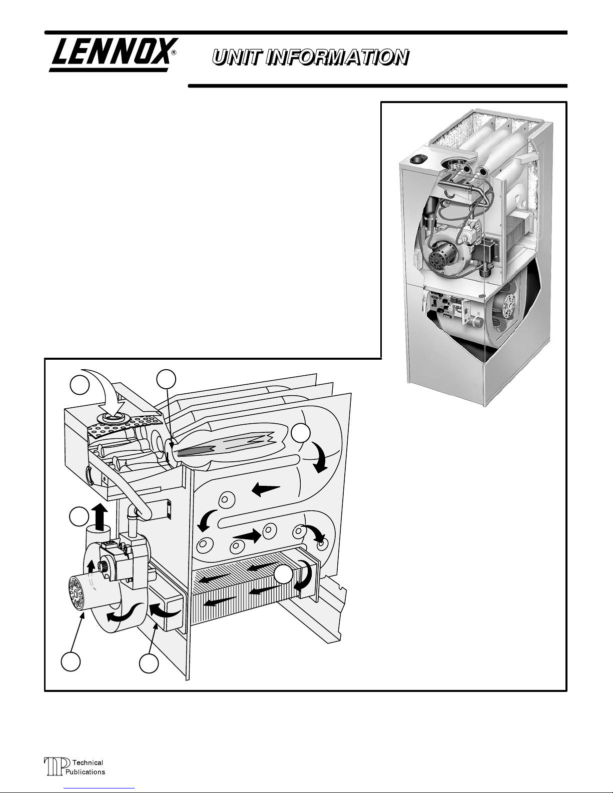
G26 series units are high−efficiency upflow gas furnaces manufactured with
DuralokPlus aluminized steel clamshell-type heat exchangers. G26 units
are available in heating capacities of 50,000 to 125,000 Btuh and cooling
applications up to 5 tons. Refer to Engineering Handbook for proper sizing.
Units are factory equipped for use with natural gas. A kit is available for conversion to LPG operation. G26−1 and −2 model units use electronic (intermittent pilot) ignition. G26−3, −4, −5 and −6 model units feature the Lennox SureLight silicon nitride ignition system. Each unit meets the California Nitrogen Oxides (NOx) Standards and California Seasonal Efficiency requirements without modification. All units use a redundant gas valve to assure
safety shut−off as required by A.G.A. or C.G.A.
Information contained in this manual is intended for use by qualified service
technicians only. All specifications are subject to change. Procedures outlined in this manual are presented as a recommendation only and do not supersede or replace local or state codes. In the absence of local or state
codes, the guidelines and procedures outlined in this manual (except where
noted) are recommended only.
G26
Corp. 9721−L11
Revised 08−2004
2
7
1
3
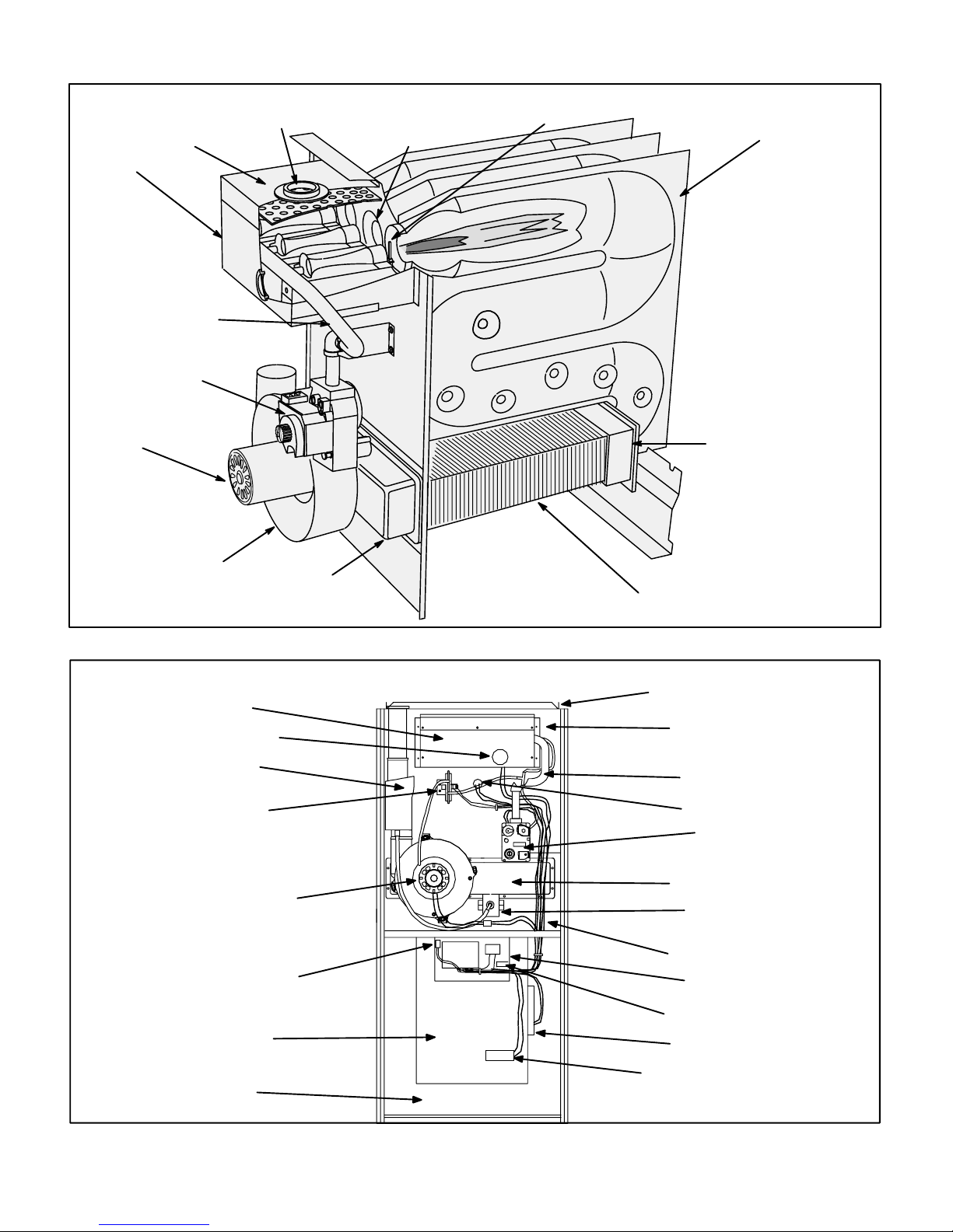
G26 FURNACE
4
FIGURE 1
5
G26 HEAT EXCHANGE ASSEMBLY
Combustion Process:
1. A call for heat starts the combustion air blower.
2. Outdoor air is drawn through pipe into the burner
compartment where it mixes with gas in a conventional style inshot burner.
3. The SureLight ignition system lights the burners.
4. Combustion products are drawn downward
through the heat exchanger. Heat is extracted
as indoor air passes across the outside surface
of the metal.
5. Latent heat is removed from the combustion
products as air passes through the coil. Condensate (water) is formed as the combustion products cool.
6. As the combustion products exit the coil, condensate is collected and drained away.
7. Combustion products are pulled from the heat
exchanger and forced into the flue.
6
Page 1
© 1997 Lennox Industries Inc.
Litho U.S.A.
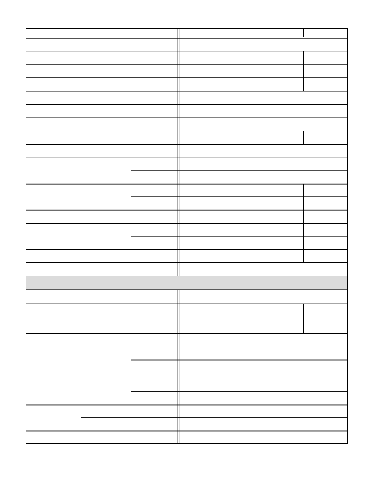
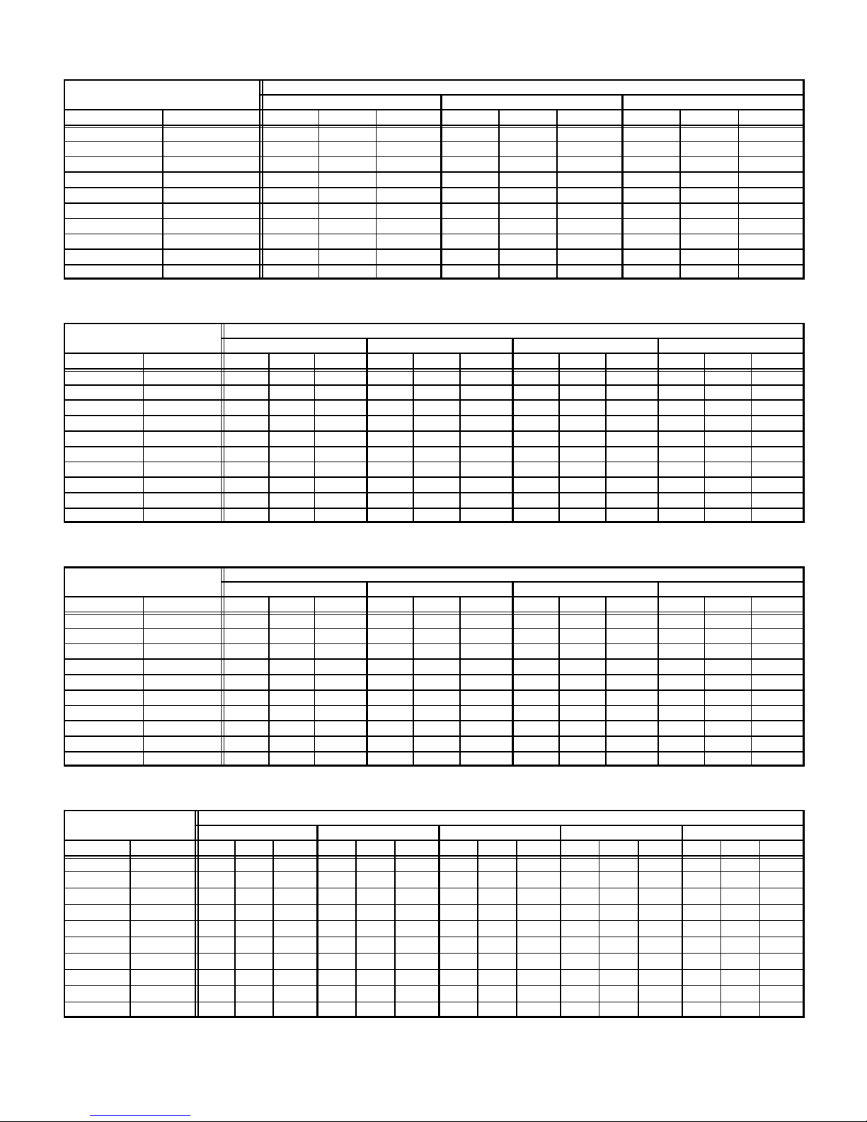
SPECIFICATIONS
Gas Piping Size I.P.S
Blower wheel nominal
g
Nominal cooling
Vent/Intake Air Roof
Twinning Kits
Model No. G26Q2-50 G26Q3-50 G26Q3-75 G26Q4/5-75
Input Btuh (kW) 50,000 (14.7) 75,000 (22.0)
Output Btuh (kW) 46,000 (13.5) 47,000 (13.8) 70,000 (20.5) 69,000 (20.2)
A.F.U.E. 92% 92.4% 92.0% 92.0%
California Seasonal Efficiency 85.9% 86.5% 86.3% 83.8%
Exhaust pipe connection (PVC) diameter in. (mm) 2 (51)
Intake pipe connection (PVC) diameter in. (mm) 2 (51)
Condensate drain connection (PVC) in. (mm) 1/2 (12.7)
Temperature rise range F (C) 40−70 (22−39) 30−60 (17−33) 40−70 (22−39) 20−50 (11−28)
High static certified by (A.G.A./C.G.A.) in. wg. (Pa) .50 (125)
Gas Piping Size I.P.S.
Natural or LPG/propane
Blower wheel nominal
diameter x width
Blower motor output hp (W) 1/5 (149) 1/3 (249) 3/4 (560)
Nominal coolin
that can be added
Shipping weight lbs. (kg) 1 package 150 (68) 157 (71) 157 (71) 182 (83)
Electrical characteristics 120 volts 60 hertz 1 phase (all models) (less than 12 amps)
.
in. 1/2
mm 12.7
in. 10 x 7 10 x 8 11-1/2 x 9
mm 254 x 178 254 x 203 292 x 229
Tons 1 to 2 2 to 3 3-1/2 to 5
kW 3.5 to 7.0 3.5 to 10.6 12.3 to 17.6
Optional Accessories (Must Be Ordered Extra)
LPG/Propane kit (optional) 65K27 (all models)
Filter and Filter Rack Kits
No. & sizeoffilters − in. (mm)
Concentric Vent/Intake Air/Roof Termination Kit (optional) 60G77 1 1/2 inch (38 mm)
Single (44J20) Ten Pack (66K61)
(1) 14 x 25 x 1 (356 x 635 x 25)
Single (44J21)
Ten Pack (66K62)
(1) 20 x 25 x 1
(508 x 635 x 25)
Termination Kit (optional) vent size
Termination Kit (optional) vent size
Twinning Kits
Continuous Low Speed Blower Switch (optional) 44J06 (−1 and −2 models) Not used with Twinning Kits
Annual Fuel Utilization Efficiency based on U.S. DOE test procedures and FTC labeling regulations. Isolated combustion system rating for non-weatherized furnaces.
Polyurethane frame type filter.
Determine from venting tables proper intake and exhaust pipe size and termination kit required.
Vent/Intake Air Roof
Vent/Intake Air Wall
(optional)
Non-continuous low speed 64H88 (all models)
Continuous low speed 35J93 (all models)
2 inch (51 mm) 15F75
3 inch (76 mm) 44J41
2 inch (51 mm)
3 inch (76 mm) 44J40 (close couple) or 81J20 (WTK close couple)
15F74 (ring kit) 22G44 (close couple) 30G28 (WTK close couple)
30G79 (WTKX close couple with extension riser)
Page 2
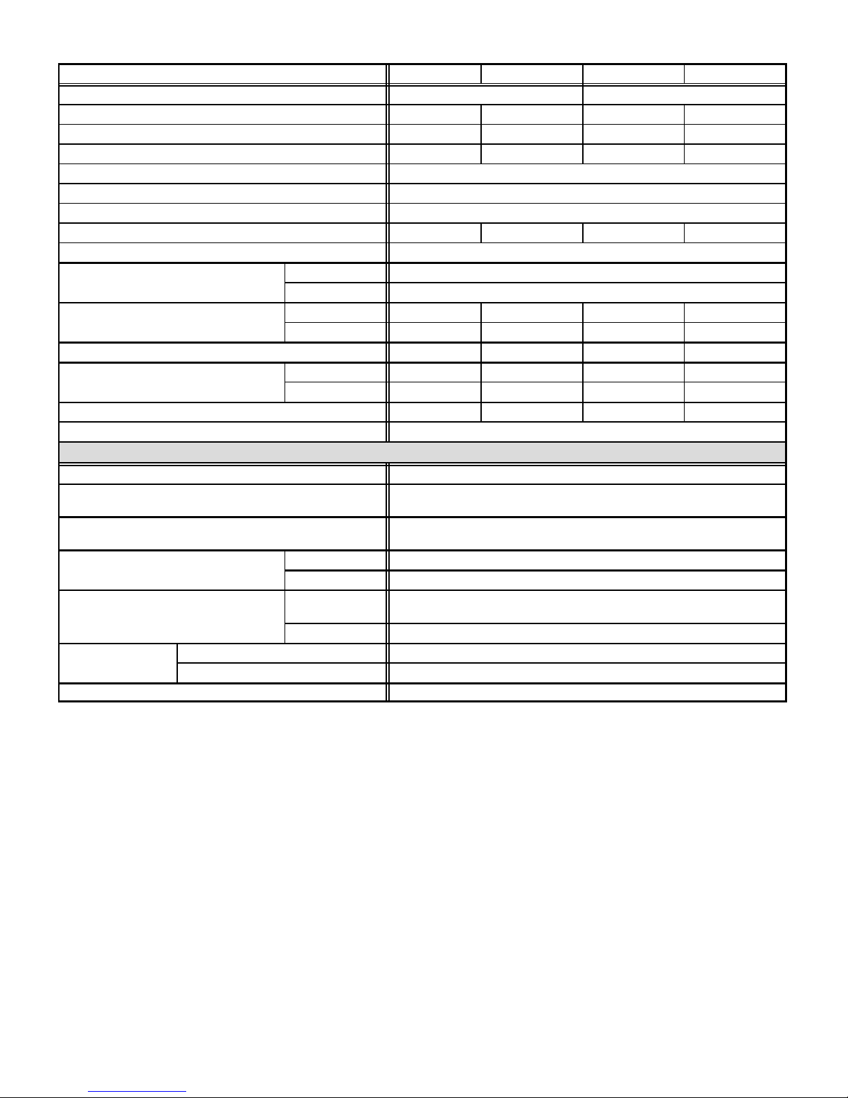
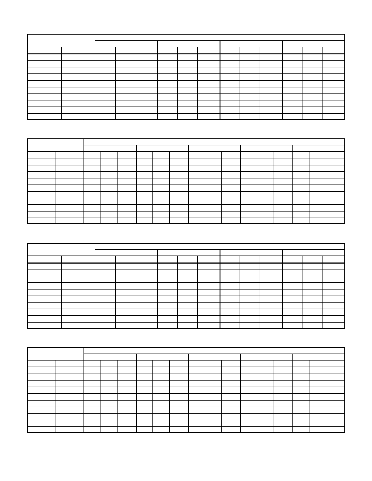
SPECIFICATIONS
Gas Piping Size I.P.S
Blower wheel nominal
g
Nominal cooling
Vent/Intake Air Roof
Twinning Kits
Model No. G26Q3/4-100 G26Q4/5-100 G26Q3/4-125 G26Q4/5-125
Input Btuh (kW) 100,000 (29.3) 125,000 (36.6)
Output Btuh (kW) 91,000 (26.7) 93,000 (27.2) 115,000 (33.7) 116,000 (34.0)
A.F.U.E. 92.0% 92.0% 91.0% 92.0%
California Seasonal Efficiency 86.6% 85.8% 87.5% 87.0%
Exhaust pipe connection (PVC) diameter in. (mm) 2 (51)
Intake pipe connection (PVC) diameter in. (mm) 3 (76)
Condensate drain connection (PVC) in. (mm) 1/2 (12.7)
Temperature rise range F (C) 50−80 (28−44) 40−70 (22−39) 55−85 (31−47) 50−80 (28−44)
High static certified by (A.G.A./C.G.A.) in. wg. (Pa) .50 (125)
Gas Piping Size I.P.S.
Natural or LPG/propane
Blower wheel nominal
diameter x width
Blower motor output hp (W) 1/2 (373) 3/4 (560) 1/2 (373) 3/4 (560)
Nominal coolin
that can be added
Shipping weight lbs. (kg) 1 package 186 (84) 198 (90) 218 (99) 218 (99)
Electrical characteristics 120 volts 60 hertz 1 phase (all models) (less than 12 amps)
LPG/Propane kit (optional) 65K27 (all models)
Filter and Filter Rack Kits
No. & sizeoffilters − in. (mm)
Concentric Vent/Intake Air/Roof Termination Kit (optional)
Vent/Intake Air Roof
Termination Kit (optional) vent size
Vent/Intake Air Wall
Termination Kit (optional) vent size
Twinning Kits
(optional)
Continuous Low Speed Blower Switch (optional) 44J06 (−1 and −2 models) Not used with Twinning Kits
Annual Fuel Utilization Efficiency based on U.S. DOE test procedures and FTC labeling regulations. Isolated combustion system rating for non-weatherized furnaces.
Polyurethane frame type filter.
Determine from venting tables proper intake and exhaust pipe size and termination kit required.
NOTE − 2 inch x 3 inch (51 mm x 76 mm) adaptor is furnished with -100 and -125 furnaces for exhaust pipe connection.
.
Non-continuous low speed 64H88 (all models)
Continuous low speed 35J93 (all models)
in. 1/2
mm 12.7
in. 10 x 10 11-1/2 x 9 10 x 10 11-1/2 x 9
mm 254 x 254 292 x 229 254 x 254 292 x 229
Tons 2 to 4 3-1/2 to 5 2 to 4 3-1/2 to 5
kW 7.0 to 14.1 12.3 to 17.6 7.0 to 14.1 12.3 to 17.6
Optional Accessories (Must Be Ordered Extra)
Single (44J21) Ten Pack (66K62)
(1) 20 x 25 x 1 (508 x 635 x 25)
33K97 2 inch (51 mm)
60L46 − 3 inch (76 mm)
2 inch (51 mm) 15F75
3 inch (76 mm) 44J41
2 inch (51 mm)
3 inch (76 mm) 44J40 (close couple) 81J20 (WTK close couple)
15F74 (ring kit) 22G44 (close couple) 30G28 (WTK close couple)
30G79 (WTKX close couple with extension riser)
Page 3
BLOWER PERFORMANCE DATA
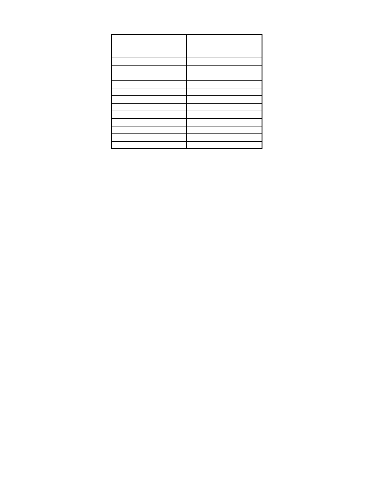
FILTER AIR RESISTANCE
cfm (L/s) in. w.g. (Pa)
0 (0) 0.00 (0)
200 (95) 0.01 (0)
400 (190) 0.03 (5)
600 (285) 0.04 (10)
800 (380) 0.06 (15)
1000 (470) 0.09 (20)
1200 (565) 0.12 (30)
1400 (660) 0.15 (35)
1600 (755) 0.19 (45)
1800 (850) 0.23 (55)
2000 (945) 0.27 (65)
2200 (1040) 0.33 (80)
2400 (1130) 0.38 (95)
2600 (1225) 0.44 (110)
Page 4
BLOWER PERFORMANCE DATA
External Static
External Static
External Static
External Static
G26Q2-50 BLOWER PERFORMANCE
External Static
Pressure
in. w.g. Pa cfm L/s Watts cfm L/s Watts cfm L/s Watts
0 0 1115 525 495 885 415 360 720 340 280
.10 25 1095 515 475 880 415 350 700 330 265
.20 50 1065 505 465 855 405 340 680 320 260
.30 75 1035 490 445 830 390 325 660 310 250
.40 100 995 470 425 755 355 315 645 305 235
.50 125 950 450 405 755 355 300 625 295 225
.60 150 900 425 390 740 350 280 540 255 215
.70 175 815 385 365 660 310 255 530 250 205
.80 200 610 290 340 585 275 240 360 170 180
.90 225 590 280 315 390 185 215 - - - - - - - - - - - -
NOTE All air data is measured external to unit with 1 in. (25 mm) cleanable foam filter (not furnished) in place. Also see Filter Air Resistance table.
High Medium Low
G26Q3-50 BLOWER PERFORMANCE
External Static
Pressure
in. w.g. Pa cfm L/s Watts cfm L/s Watts cfm L/s Watts cfm L/s Watts
0 0 1485 700 590 1275 600 485 1045 495 390 840 395 310
.10 25 1445 680 565 1250 590 460 1030 485 375 830 390 300
.20 50 1390 655 545 1225 580 445 1010 475 365 815 385 290
.30 75 1345 635 520 1190 560 425 985 465 345 790 375 285
.40 100 1290 610 500 1150 545 405 955 450 335 780 370 275
.50 125 1225 580 480 1095 515 385 920 435 315 735 345 255
.60 150 1160 545 460 1030 485 365 875 415 300 700 330 240
.70 175 1075 505 440 950 450 345 855 405 280 600 285 220
.80 200 975 460 415 865 410 315 645 305 250 510 240 195
.90 225 845 400 385 615 290 265 545 255 225 375 175 180
NOTE All air data is measured external to unit with 1 in. (25 mm) cleanable foam filter (not furnished) in place. Also see Filter Air Resistance table.
High Medium-High Medium-Low Low
Air Volume and Motor Watts at Specific Blower Taps
Air Volume and Motor Watts at Specific Blower Taps
G26Q3-75 BLOWER PERFORMANCE
External Static
Pressure
in. w.g. Pa cfm L/s Watts cfm L/s Watts cfm L/s Watts cfm L/s Watts
0 0 1490 705 650 1340 630 540 1060 500 440 870 410 360
.10 25 1435 675 625 1305 615 515 1050 495 425 865 410 350
.20 50 1385 655 605 1260 595 490 1025 485 405 850 400 335
.30 75 1330 630 580 1215 575 470 1000 470 385 835 395 325
.40 100 1260 595 560 1160 545 445 965 455 365 810 380 310
.50 125 1200 565 540 1100 520 420 920 435 345 770 365 290
.60 150 1125 530 515 1035 490 400 870 410 325 735 345 280
.70 175 1035 490 495 960 455 375 780 370 305 685 325 265
.80 200 935 440 475 865 410 345 725 340 285 - - - - - - - - - - - .90 225 805 380 445 630 295 295 540 255 240 - - - - - - - - - - - -
NOTE All air data is measured external to unit with 1 in. (25 mm) cleanable foam filter (not furnished) in place. Also see Filter Air Resistance table.
High Medium-High Medium-Low Low
Air Volume and Motor Watts at Specific Blower Taps
G26Q4/5-75 BLOWER PERFORMANCE
External Static
Pressure
in. w.g. Pa cfm L/s Watts cfm L/s Watts cfm L/s Watts cfm L/s Watts cfm L/s Watts
0 0 2415 1140 1240 2120 1000 1015 1875 885 855 1635 770 705 1430 675 585
.10 25 2330 1100 1200 2090 985 1005 1835 865 835 1615 760 700 1420 670 585
.20 50 2265 1070 1165 2045 965 990 1795 845 815 1580 745 690 1390 655 580
.30 75 2210 1045 1145 2000 945 970 1765 835 810 1545 730 675 1365 645 575
.40 100 2145 1010 1110 1950 920 955 1720 810 795 1510 715 670 1340 630 570
.50 125 2075 980 1085 1885 890 930 1680 795 785 1475 695 665 1310 620 565
.60 150 2000 945 1060 1825 860 910 1630 770 770 1435 675 655 1270 600 555
.70 175 1935 915 1040 1775 840 895 1565 740 755 1395 660 645 1220 575 545
.80 200 1840 870 1005 1705 805 870 1515 715 745 1345 635 630 1165 550 535
.90 225 1760 830 980 1610 760 845 1455 685 725 1275 600 615 1110 525 530
NOTE All air data is measured external to unit with 1 in. (25 mm) cleanable foam filter (not furnished) in place. Also see Filter Air Resistance table.
High Medium-High Medium Medium-Low Low
Air Volume and Motor Watts at Specific Blower Taps
Page 5
BLOWER PERFORMANCE DATA
External Static
External Static
External Static
External Static
G26Q3/4-100 BLOWER PERFORMANCE
External Static
Pressure
in. w.g. Pa cfm L/s Watts cfm L/s Watts cfm L/s Watts cfm L/s Watts
0 0 2065 975 920 1760 830 735 1570 740 655 1245 590 520
.10 25 2000 945 875 1730 815 705 1550 730 625 1240 585 490
.20 50 1925 910 845 1685 795 675 1515 715 590 1225 580 470
.30 75 1840 870 800 1625 765 630 1475 695 565 1210 570 455
.40 100 1740 820 760 1550 730 595 1415 670 535 1165 550 430
.50 125 1650 780 730 1460 690 560 1335 630 500 111 0 525 405
.60 150 1545 730 700 1370 645 530 1260 595 475 1045 495 385
.70 175 1420 670 660 1250 590 495 1170 550 445 950 450 355
.80 200 1270 600 620 1110 525 445 1025 485 395 825 390 325
.90 225 1045 495 560 965 455 405 885 420 360 700 330 290
NOTE All air data is measured external to unit with 1 in. (25 mm) cleanable foam filter (not furnished) in place. Also see Filter Air Resistance table.
High Medium-High Medium-Low Low
G26Q4/5-100 BLOWER PERFORMANCE
External Static
Pressure
in. w.g. Pa cfm L/s Watts cfm L/s Watts cfm L/s Watts cfm L/s Watts cfm L/s Watts
0 0 2400 1135 1255 2185 1030 1070 1940 915 905 1740 820 765 1570 740 665
.10 25 2350 1110 1230 2150 1015 1055 1920 905 885 1710 805 755 1525 720 645
.20 50 2290 1080 1185 2105 995 1025 1875 885 865 1685 795 740 1505 710 640
.30 75 2225 1050 1170 2060 970 1005 1845 870 850 1655 780 730 1485 700 630
.40 100 2165 1020 1130 2010 950 985 1805 850 835 1620 765 720 1450 685 620
.50 125 2105 995 111 5 1950 920 960 1755 830 810 1585 750 700 1415 670 605
.60 150 2040 965 1080 1895 895 940 1700 800 790 1540 725 690 1380 650 595
.70 175 1955 925 1045 1820 860 915 1640 775 775 1475 695 670 1340 630 590
.80 200 1850 875 1005 1730 815 885 1580 745 755 1430 675 660 1290 610 580
.90 225 1770 835 985 1650 780 855 1505 710 740 1370 645 645 1225 580 565
NOTE All air data is measured external to unit with 1 in. (25 mm) cleanable foam filter (not furnished) in place. Also see Filter Air Resistance table.
High Medium-High Medium Medium-Low Low
Air Volume and Motor Watts at Specific Blower Taps
Air Volume and Motor Watts at Specific Blower Taps
G26Q3/4-125 BLOWER PERFORMANCE
External Static
Pressure
in. w.g. Pa cfm L/s Watts cfm L/s Watts cfm L/s Watts cfm L/s Watts
0 0 2070 975 920 1735 820 725 1555 735 640 1235 585 500
.10 25 2010 950 885 1710 805 700 1535 725 625 1225 580 490
.20 50 1950 920 850 1675 790 680 1500 710 600 1210 570 470
.30 75 1975 930 820 1620 765 645 1465 690 575 1185 560 455
.40 100 1785 840 775 1560 735 615 1415 670 545 1140 540 435
.50 125 1700 800 745 1475 695 575 1345 635 520 1090 515 415
.60 150 1585 750 705 1410 665 555 1275 600 490 1035 490 390
.70 175 1475 695 675 1310 620 515 1185 560 460 975 460 370
.80 200 1350 635 640 1200 565 485 1090 515 425 865 410 340
.90 225 1200 565 595 1080 510 445 965 455 385 715 335 300
NOTE All air data is measured external to unit with 1 in. (25 mm) cleanable foam filter (not furnished) in place. Also see Filter Air Resistance table.
High Medium-High Medium-Low Low
Air Volume and Motor Watts at Specific Blower Taps
G26Q4/5-125 BLOWER PERFORMANCE
External Static
Pressure
in. w.g. Pa cfm L/s Watts cfm L/s Watts cfm L/s Watts cfm L/s Watts cfm L/s Watts
0 0 2400 1135 1210 2175 1025 1040 1965 925 895 1790 845 780 1610 760 670
.10 25 2315 1090 1175 2125 1005 1025 1930 910 875 1760 830 770 1580 745 660
.20 50 2255 1065 1150 2080 980 1000 1880 885 860 1740 820 755 1550 730 645
.30 75 2195 1035 1130 2030 960 975 1840 870 835 1710 805 750 1520 715 635
.40 100 2120 1000 1100 1970 930 960 1790 845 815 1665 785 730 1495 705 630
.50 125 2050 965 1080 1910 900 934 1745 825 800 1620 765 715 1460 690 620
.60 150 1985 935 1050 1840 870 905 1685 795 785 1565 740 705 1415 670 610
.70 175 1885 890 1020 1770 835 890 1635 765 775 1515 715 685 1370 645 595
.80 200 1815 855 1005 1690 800 860 1570 740 750 1450 685 670 1315 620 580
.90 225 1735 820 980 1615 760 835 1485 700 725 1385 655 655 1245 590 565
NOTE All air data is measured external to unit with 1 in. (25 mm) cleanable foam filter (not furnished) in place. Also see Filter Air Resistance table.
High Medium-High Medium Medium-Low Low
Air Volume and Motor Watts at Specific Blower Taps
Page 6
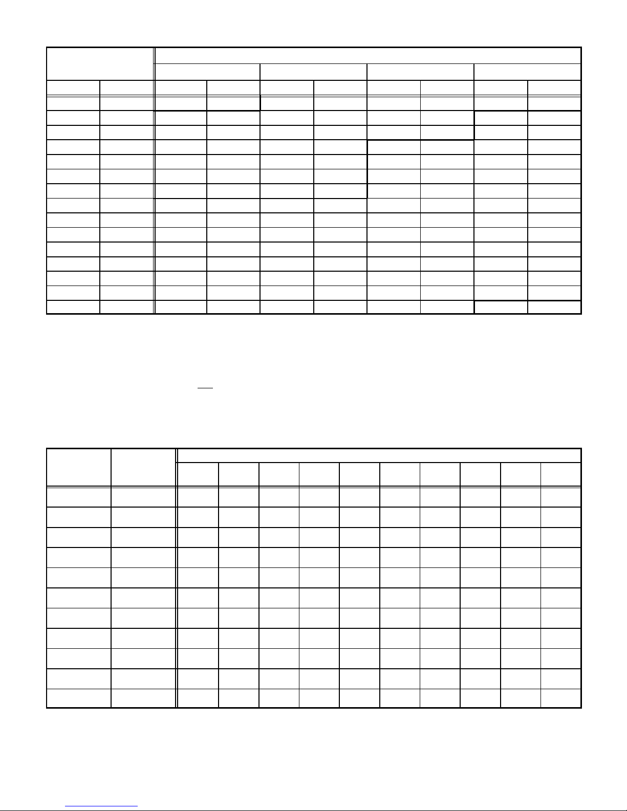
INTAKE and EXHAUST PIPE VENTING TABLE
Nominal
Internal
Vent Pipe
Maximum
Equivalent Length
50,000 Btuh (14.7 kW) 75,000 Btuh (22.0 kW) 100,000 Btuh (29.3 kW) 125,000 Btuh (36.6 kW)
Minimum Vent Pipe Diameter Required
Feet Meters in. mm in. mm in. mm in. mm
15 4.6 1-1/2 38 2 51 2 51 2 51
20 6.1 2 51 2 51 2 51 3 76
25 7.6 2 51 2 51 2 51 3 76
30 9.1 2 51 2 51 3 51 3 76
40 12.2 2 51 2 51 3 51 3 76
50 15.2 2 51 2 51 3 51 3 76
55 16.8 2 51 2 51 3 76 3 76
60 18.3 3 76 3 76 3 76 3 76
70 21.3 3 76 3 76 3 76 3 76
80 24.4 3 76 3 76 3 76 3 76
90 27.4 3 76 3 76 3 76 3 76
100 30.5 3 76 3 76 3 76 3 76
110 33.5 3 76 3 76 3 76 3 76
120 36.6 3 76 3 76 3 76 3 76
130 39.6 3 76 3 76 3 76 - - - - - - - -
MINIMUM PIPE LENGTHS FOR FURNACES G26-50 5 feet (1.5 m) with two 90 elbows of 1-1/2 inch (38 mm) diameter pipe. (15 equivalent feet (4.6 m) total).
VENTING NOTES One 90elbow is equivalent to 5 feet (1.5 m) of straight vent pipe.
Two 45 elbows are equal to one 90 elbow.
One 45 elbow is equivalent to 2.5 feet (.75 m) of straight vent pipe.
One foot (305 mm) length of 2 in. (51 mm) diameter pipe is equivalent to 8 feet (2.4 m) of 3 in. (76 mm) diameter pipe.
Intake and Exhaust pipes must be the same diameter.
2 inch x 3 inch (51 mm x 76 mm) adaptor is furnished with -100 and -125 furnaces for exhaust pipe connection.
Exhaust pipe must terminate with 1-1/2 inch (38 mm) diameter pipe for furnaces using1-1/2 (38 mm) or 2 inch (51 mm) diameter pipe runs.
Exhaust pipe must terminate with 2 inch (51 mm) diameter pipe for furnaces using 3 inch (76 mm) diameter pipe runs.
See pages 10 thru 12 for Termination Kits available.
G26-75 5 feet (1.5 m) with two 90 elbows of 2 inch (51 mm) diameter pipe. (15 equivalent feet (4.6 m) total).
G26-100 5 feet (1.5 m) with two 90 elbows of 2 inch (51 mm) diameter pipe. (15 equivalent feet (4.6 m) total).
G26-125 5 feet (1.5 m) with two 90 elbows of 2 inch (51 mm) diameter pipe. (15 equivalent feet (4.6 m) total).
GAS PIPE CAPACITY − FT3/HR (kL/HR)
Nominal Internal
Iron Pipe Size
−Inches(mm)
1/4
(6.35)
3/8
(9.53)
1/2
(12.7)
3/4
(19.05)
1
(25.4)
1−1/4
(31.75)
1−1/2
(38.1)
2
(50.8)
2−1/2
(63.5)
3
(76.2)
4
(101.6)
Diameter
−Inches(mm)
.364
(9.246)
.493
(12.522)
.622
(17.799)
.824
(20.930)
1.049
(26.645)
1.380
(35.052)
1.610
(40.894)
2.067
(52.502)
2.469
(67.713)
3.068
(77.927)
4.026
(102.260)
10
(3.048)20(6.096)30(9.144)40(12.192)50(15.240)60(18.288)70(21.336)80(24.384)90(27.432)
43
(1.13)
95
(2.69)
175
(4.96)
360
(10.19)
680
(19.25)
1400
(39.64)
2100
(59.46)
3950
(111.85)
6300
(178.39)
11000
(311.48)
23000
(651.27)
29
(.82)
65
(1.84)
120
(3.40)
250
(7.08)
465
(13.17)
950
(26.90)
460
(41.34)
2750
(77.87)
4350
(123.17)
7700
(218.03)
15800
(447.39)
24
(.68)
52
(1.47)
97
(2.75)
200
(5.66)
375
(10.62)
770
(21.80)
1180
(33.41)
2200
(62.30)
3520
(99.67)
6250
(176.98)
12800
(362.44)
NOTE−Capacity given in cubic feet of gas per hour (kilo liters of gas per hour) and based on 0.60 specific gravity gas.
Length of Pipe−Feet(m)
20
(.57)
45
(1.27)
82
(2.32)
170
(4.81)
320
(9.06)
660
(18.69)
990
(28.03)
1900
(53.80)
3000
(84.95)
5300
(150.07)
10900
(308.64)
18
(.51)
40
(1.13)
73
(2.07)
151
(4.28)
285
(8.07)
580
(16.42)
900
(25.48)
1680
(47.57)
2650
(75.04)
4750
(134.50)
9700
(274.67)
16
(.45)
36
(1.02)
66
(1.87)
138
(3.91)
260
(7.36)
530
(15.01)
810
(22.94)
1520
(43.04)
2400
(67.96)
4300
(121.76)
8800
(249.18)
15
(.42)
33
(.73)
61
(1.73)
125
(3.54)
240
(6.80)
490
(13.87)
750
(21.24)
1400
(39.64)
2250
(63.71)
3900
(110.43)
8100
(229.36)
14
(.40)
31
(.88)
57
(1.61)
118
(3.34)
220
(6.23)
460
(13.03)
690
(19.54)
1300
(36.81)
2050
(58.05)
3700
(104.77)
7500
(212.37)
13
(.37)
29
(.82)
53
(1.50)
110
(3.11)
205
(5.80)
430
(12.18)
650
(18.41)
1220
(34.55)
1950
(55.22)
3450
(97.69)
7200
(203.88)
100
(30.480)
12
(.34)
27
(.76)
50
(1.42)
103
(2.92)
195
(5.52)
400
(11.33)
620
(17.56)
1150
(32.56)
1850
(52.38)
3250
(92.03)
6700
(189.72)
Page 7
GLASS FIBER GASKET
FRESH AIR
INTAKE FITTING
BURNER BOX
ASSEMBLY
PATCH
PLATE
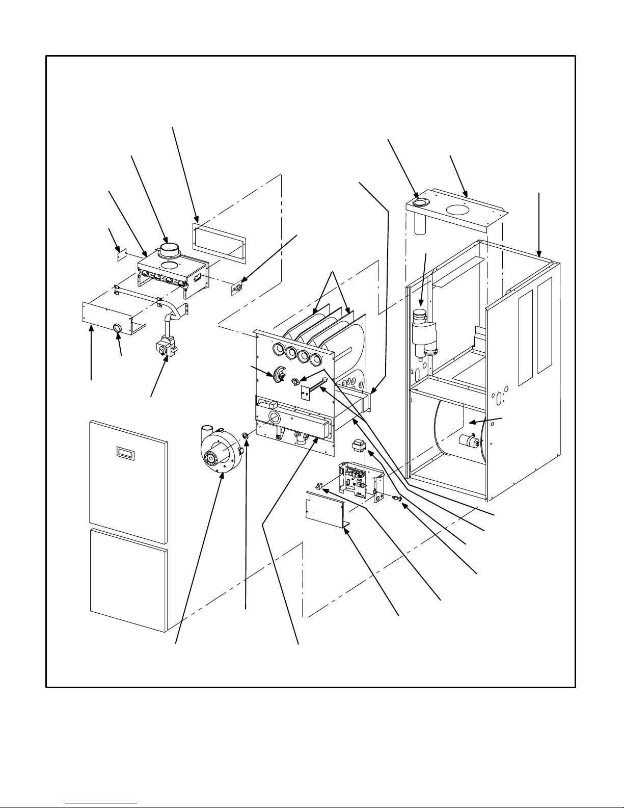
G26−3 THROUGH −6 COMPONENTS
FLUE COLLAR
WARM
HEADER
(COLLECTOR)
BOX
PATCH PLATE WITH
BARBED FITTING
AND FLAME
ROLL−OUT SWITCH
DuralokPlus
HEAT EXCHANGER
ASSEMBLY
TM
TOP CAP
CABINET
FLUE
TRANSITION
FLAME SIGHT
BURNER
BOX
COVER
GLASS
GAS VALVE AND
MANIFOLD
BURNER
ACCESS
PANEL
BLOWER
ACCESS
DOOR
COMBUSTION AIR
BLOWER
COMBUSTION AIR
PROVE (PRESSURE)
SWITCH
COMBUSTION AIR
ORIFICE
SUPPLY
AIR
BLOWER
PRIMARY LIMIT
(ALTERNATE STYLES)
CONDENSER COIL
CONTROL TRANSFORMER
CONTROL VOLTAGE
CIRCUIT BREAKER
DOOR INTERLOCK
SWITCH
CONTROL BOX COVER
COLD HEADER
(COLLECTOR)
BOX
FIGURE 1
Page 8
BURNER
ACCESS
COVER
BURNER BOX
MANIFOLD
GAS VALVE
FRESH AIR INTAKE
FITTING
G26 HEAT EXCHANGER
CORBEL ORIFICE
CUPS
SURELIGHT IGNITOR LENNOX DURALOKPLUS
HEAT EXCHANGER AS-
SEMBLY
COMBUSTION AIR
BLOWER MOTOR
COMBUSTION
AIR BLOWER
FLAME SIGHT GLASS
FLUE TRANSITION
DIFFERENTIAL
(COMBUSTION AIR)
PRESSURE SWITCH
BURNER
BOX
COLD HEADER
(COLLECTOR )
BOX
FIGURE 2
G26 GENERAL PARTS ORIENTATION
WARM HEAD
(COLLECTOR)
BOX
CONDENSER COIL
SUPPLY AIR DUCT
FLANGE
UPPER VEST PANEL
GAS MANIFOLD
PRIMARY LIMIT
GAS VALVE
COMBUSTION AIR BLOWER
DOOR INTERLOCK
SWITCH
BLOWER HOUSING
BLOWER
COMPARTMENT
COLD HEADER BOX
HEADER BOX
CONDENSATE
TRAP
LOWER VEST PANEL
CONTROL BOX
CIRCUIT BREAKER
BLOWER MOTOR
BLOWER MOTOR CAPACITOR
FIGURE 3
Page 9
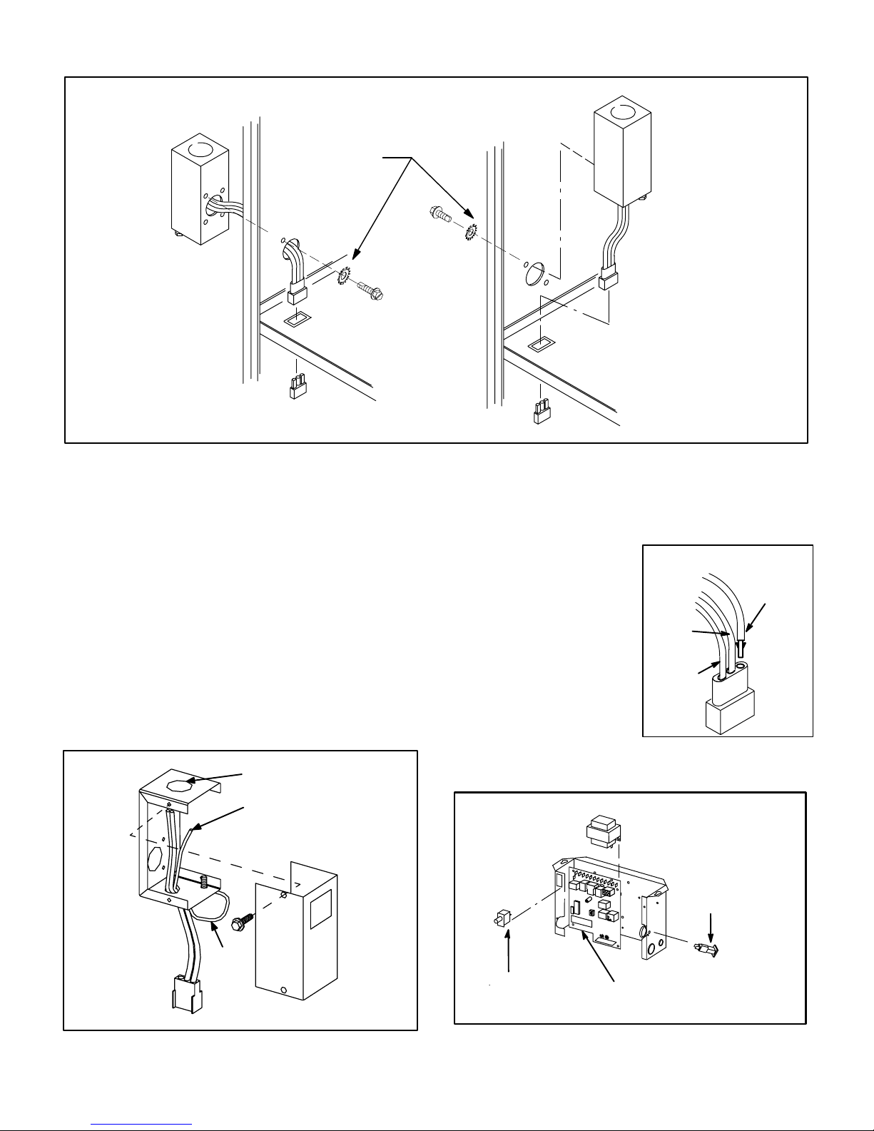
OUTSIDE INSTALLATION
MAKE-UP BOX
MAKE-UP BOX INSTALLATION
Box may be installed inside or outside cabinet and may
be installed on left side or right side of cabinet
STAR WASHERS
MUST BREAK
PAINT ON UNIT
CABINET FOR
PROPER
GROUND.
UNIT
CABINET
INSIDE INSTALLATION
MAKE-UP BOX
Line Voltage Enters Through
Knockout In Make-Up Box. J69
Passes Through Side Knockout
Into Side Of Unit.
JACK J69
BLOWER MULLION
PLUG P69
FIGURE 4
I−UNIT COMPONENTS
G26 unit components are shown in figure 1. General parts orientation is shown in figure 3. The gas valve, ignition control
and burners can be accessed by removing the burner access
panel. The blower and blower controls can be accessed by
removing the blower access door.
G26 units are designed for bottom and side return air. The
panels are designed to be knocked-out (bottom return) or
cut-out (side return) as required for return air duct connection.
A−Make-Up Box (Figure 5)
The line voltage make-up box is shown in figure 5. The box
may be installed inside or outside the unit and may be
installed on the unit left or right side (figure 4).
MAKE-UP BOX
BOX
POWER ENTRY KNOCKOUT
120V LINE VOLTAGE
PIGTAIL CONNECTIONS
COVER
Line Voltage Enters Make-Up
Box Through Side Of Unit and
J69 Passes Through Bottom
Knockout in Make-Up Box.
BLOWER MULLION
An accessory (brown) output wire is provided with the makeup box. The wire provides a 120V connection for optional accessories such as electronic air cleaner or humidifier. If used,
the wire is field installed in J69 jack plug by inserting the pin
of the brown wire into the open
socket of the jack. See figure
6. 120V accessories rated up
to 4 amps total may be connected to this wire. The neutral
leg of the accessory is con-
INSTALLING BROWN
ACCESSORY WIRE TO J69
BROWN
WHITE
NEUTRAL
nected to the neutral white
wire in the make-up box. The
accessory terminal is energized whenever the blower is
in operation.
BLACK
J69
FIGURE 6
B−Control Box Components
G26 CONTROL BOX
TRANSFORMER
UNIT
GROUND
JACK J69
to blower deck
Box may be installed inside or outside unit. See Figure 4
TO BLOWER MULLION
FIGURE 5
Page 10
DOOR
INTERLOCK
SWITCH
SURELIGHT CONTROL
(−3 through −6 models )
FIGURE 7
CIRCUIT
BREAKER

Electrical blower control components (A15), unit transformer (T1) and 24V circuit breaker (CB8) are located in the control box. In addition, a door interlock switch (S51) is located
in the control box. Jackplugs and a snap-off" terminal strip
allow the control box to be easily removed for blower service.
1− Control Transformer (T1)
A transformer located in the control box provides power to
the low voltage 24volt section of the unit. Transformers on
all models are rated 40VA with a 120V primary and a 24V
secondary.
2− Circuit Breaker (CB8)
A 24V circuit breaker is also located in the control box. The
switch provides overcurrent protection to the transformer
(T1). The breaker is rated 3A at 32V. If the current exceeds
this limit the breaker will trip and all unit operation will shutdown. The breaker can be manually reset by pressing the
button on the face.
3−Door Interlock Switch (S51)
A door interlock switch rated 14A at 125VAC is located on
the control box. The switch is wired in series with line voltage. When the blower door is removed the unit will shut
down.
4−Flame Sensor (−3 through −6 models)
A flame sensor is located on the left side of the burner support. See figure 8. The sensor is mounted on a bracket in
the burner support and the tip protrudes into the flame envelope of the left−most burner. The sensor is fastened to
burner supports and can be removed for service without
removing any part of the burners. During operation, flame
is sensed by current passed through the flame and sensing electrode. The SureLight control allows the gas valve
to remain open as long as flame signal is sensed.
NORMAL FLAME SIGNAL u 0.7 MICROAMPS
LOW FLAME SIGNAL v 0.7 MICROAMPS
MINIMUM FLAME SIGNAL v 0.15 MICROAMPS
SENSOR
3/8"
FIGURE 8
NOTE − The G26 furnace contains electronic components that are polarity sensitive. Make sure that the
furnace is wired correctly and is properly grounded.
IGNITOR
5/16"
5−Burners
All units use inshot burners (see figure 9). Burners are factory
set and do not require adjustment. A s ight g l a s s i s f u rnished in the burner box assembly for flame viewing. Always operate the unit with the burner box cover in place.
Burners can be removed as an assembly for service. Burner
maintenance and service is detailed in the MAINTENANCE
section of this manual. Each burner uses an orifice which is
precisely matched to the burner input (see nameplate for
orifice size). The orifice is threaded into the burner manifold. The burner is supported by the orifice and will easily
slide off for service. Each orifice and burner are sized specifically to the unit. Refer to Lennox Repair Parts Listing for
correct sizing information. A flame retention ring in the end of
each burner maintains correct flame length and shape and
keeps the flame from lifting off the burner head. In addition, the
burner entrance to each clamshell (Figure 2) is fitted with a
corbel cup (orifice)
TYPICAL BURNER ASSEMBLY
used to direct the
flow of combustion
products.
FIGURE 9
DANGER
Shock hazard.
Disconnect power before servicing. Control is not
field repairable. If control is inoperable, simply
replace entire control.
Can cause injury or death. Unsafe operation will
result if repair is attempted.
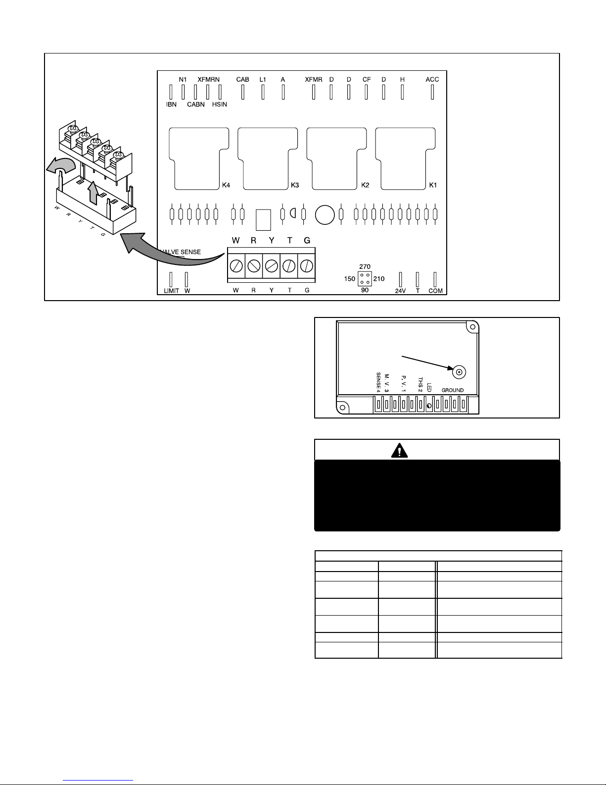
6− SureLight Ignition System A3
(−3 through −6 models)
All G26−3 through −6 model units are equipped with the
Lennox Sure − Light ignition system. The system consists
of ignition control board (figure 10 with control terminal
designations in table 1) and ignitor (figures 8 and 11). The
board and ignitor work in combination to ensure furnace
ignition and ignitor durability. The SureLight integrated
board controls all major furnace operations. The board
also features two LED lights for troubleshooting and two
accessory terminals rated at (4) four amps. See table 2
for troubleshooting diagnostic codes. Table 3 and 4 show
jack plug terminal designations. Units equipped with the
SureLight board can be used with either electronic or
electro−mechanical thermostats without modification.
The SureLight ignitor is made of durable silicon−nitride.
Ignitor longevity is also enhanced by voltage ramping by
the control board. The board finds the lowest ignitor temperature which will successfully light the burner, thus increasing the life of the ignitor.
NOTE − Do not remove blower access panel to read
SureLight LED lights. A sight glass is provided on the
access panel for viewing.
Page 11
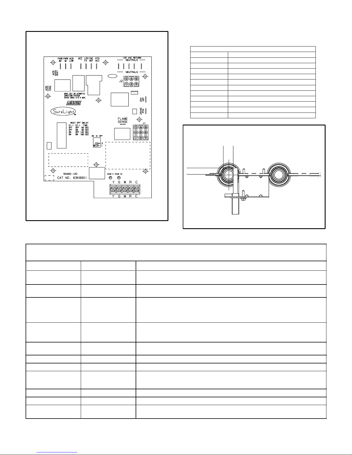
SURELIGHT CONTROL BOARD
TABLE 1
SURELIGHT CONTROL TERMINAL DESIGNATIONS
ACB COOL
ACB HEAT
PARK
ACB LOW
ACC
TX
HOT
HTG ACC
NEUTRALS
24VAC HOT
24VAC RTN
FLAME SENSE
Blower − Cooling Speed (Line Volt)
Blower − Heating Speed (Line Volt)
Alternate Blower Speeds (Dead)
Continuous Low Speed Blower
Accessory Terminal (Line Volt)
120VAC Hot to Transformer
120VAC Hot Input
Heat Only Accessory (Line Volt)
120VAC Neutrals
24VAC Hot from Transformer
24VAC Return from Transformer
Flame Sense Terminal
SURELIGHT IGNITOR
MEASUREMENT IS TO I.D.
5/8"
OF RETENTION RING
13/32’
FIGURE 10
FIGURE 11
TABLE 2
DIAGNOSTIC CODES
MAKE SURE TO ID LED’S CORRECTLY: REFER TO INSTALLATION INSTRUCTIONS FOR CONTROL BOARD LAYOUT.
LED #1 LED #2 DESCRIPTION
SIMULTANEOUS
SLOW FLASH
SIMULTANEOUS FAST
FLASH
SIMULTANEOUS
SLOW FLASH
SIMULTANEOUS FAST
FLASH
Also signaled during cooling and continues fan.
Normal operation − signaled when heating demand initiated at thermostat.
Primary or Secondary limit open. Units with board 63K8901 or 24L85: Limit must
SLOW FLASH ON
close within 5 trials for ignition or board goes into one hour limit Watchguard.
Units with board 56L83 or 97L48: Limit must close within 3 minutes or board
Pressure switch open or has opened 5 times during a single call for heat; OR:
OFF SLOW FLASH
Blocked inlet/exhaust vent; OR: Condensate line blocked; OR: Pressure switch
closed prior to activation of combustion air blower.
ALTERNATING SLOW
FLASH
SLOW FLASH OFF
ON SLOW FLASH
ON
ON
OFF
FAST FLASH SLOW FLASH
SLOW FLASH FAST FLASH
ALTERNATING FAST
FLASH
NOTE − Slow flash equals 1 Hz (one flash per second). Fast flash equals 3 Hz (three flashes per second). Drop out flame sense current < 0.15 microAmps
ALTERNATING SLOW
FLASH
ON
OFF
ON
ALTERNATING FAST
FLASH
Flame sensed without gas valve energized.
Rollout switch open. OR: 9 pin connector improperly attached.
Circuit board failure or control wired incorrectly.
Main power polarity reversed. Switch line and neutral.
Low flame signal. Measures below .7 microAmps. Replace flame sense rod.
Improper main ground or line voltage below 75 volts; OR: Broken ignitor; OR:
Power − Normal operation
goes into one hour limit Watchguard.
Watchguard − burners fail to ignite.
Open ignitor circuit.
Page 12
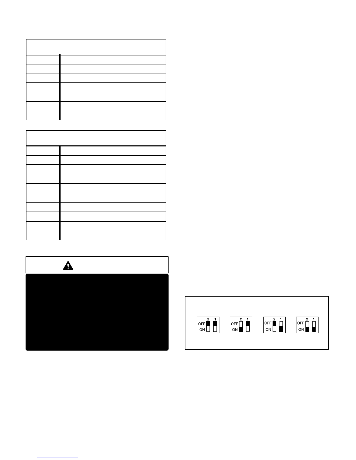
TABLE 3
SureLight BOARD J156 (J2) TERMINAL
PIN # FUNCTION
1 Ignitor
2
3
4
5
6
DESIGNATIONS
Not Used
Ignitor Neutral
Combustion Air Blower Line Voltage
Not Used
Combustion Air Blower Neutral
TABLE 4
SureLight BOARD J58 (J1) TERMINAL
PIN # FUNCTION
1 Primary Limit In
2
3
4
5
6
7
8
9
DESIGNATIONS
Gas Valve Common
Roll Out Switch Out
Gas Valve 24V
Pressure Switch In
Pressure Switch and Primary Limit Out
Not Used
Roll Out Switch In
Ground
ELECTROSTATIC DISCHARGE (ESD)
Precautions and Procedures
CAUTION
Electrostatic discharge can affect electronic
components. Take precautions during furnace
installation and service to protect the furnace’s
electronic controls. Precautions will help to
avoid control exposure to electrostatic discharge by putting the furnace, the control and
the technician at the same electrostatic potential. Neutralize electrostatic charge by touching
hand and all tools on an unpainted unit surface,
such as the gas valve or blower deck, before performing any service procedure.
a−Electronic Ignition
On a call for heat the SureLight control monitors the combustion air blower pressure switch. The control will not begin the heating cycle if the pressure switch is closed (by−
passed). Once the pressure switch is determined to be
open, the combustion air blower is energized. When the
differential in the pressure switch is great enough, the
pressure switch closes and a 15−second pre−purge begins. If the pressure switch is not proven within 2−1/2 minutes, the control goes into Watchguard−Pressure Switch
mode for a 5−minute re−set period.
After the 15−second pre−purge period, the SureLight ignitor warms up for 20 seconds after which the gas valve
opens for a 4−second trial for ignition. G26 units with board
63K89, 24L85 or 56L83: the ignitor stays energized for the
first second of the 4−second trial. Units with board 97L48:
ignitor stays energized for the full 4−second ignition trial. If
ignition is not proved during the 4−second period, the control will try four more times with an inter purge and warm−up
time between trials of 35 seconds. After a total of five trials
for ignition (including the initial trial), the control goes into
Watchguard−Flame Failure mode. After a 60−minute reset
period, the control will begin the ignition sequence again.
The SureLight control board has an added feature that
prolongs the life of the ignitor. After a successful ignition,
the SureLight control utilizes less power to energize the ignitor on successive calls for heat. The control continues to
ramp down the voltage to the ignitor until it finds the lowest
amount of power that will provide a successful ignition.
This amount of power is used for 255 cycles. On the 256th
call for heat, the control will again ramp down until the lowest power is determined and the cycle begins again.
b−Fan Time Control
The fan on time of 45 seconds is not adjustable. Fan off
time (time that the blower operates after the heat demand
has been satisfied) can be adjusted by flipping the dip
switches located on the SureLight integrated control. The
unit is shipped with a factory fan off setting of 90 seconds.
Fan off time will affect comfort and is adjustable to satisfy
individual applications. See figure 12.
FAN-OFF TIME ADJUSTMENT
60sec. 90sec. 120sec. 180sec.
To adjust fan−off timing, flip dip switch to desired setting.
FIGURE 12
7−Blower Motors and Capacitors
All G26 units use direct drive blower motors. All motors
used are 120V permanent split capacitor motors to ensure
maximum efficiency. See table 5 for ratings.
Page 13
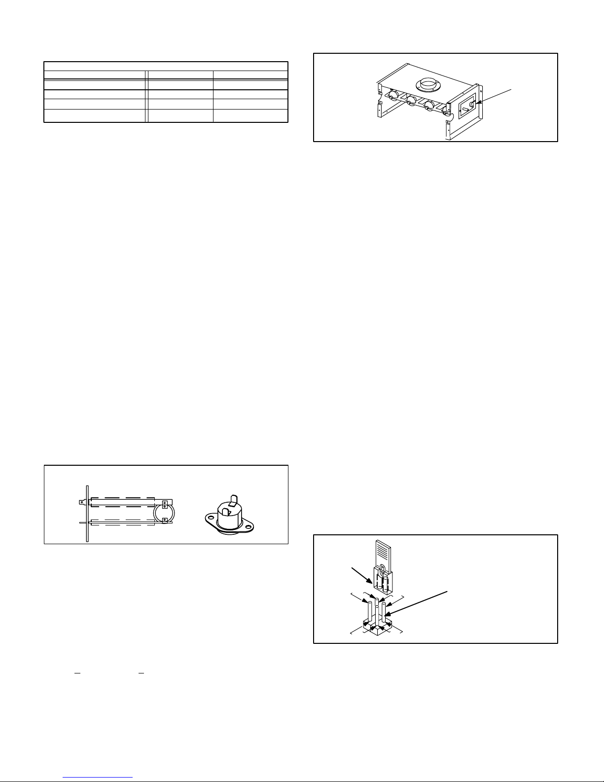
TABLE 5
BLOWER MOTOR HP
G26Q2
G26Q3
G26Q3/4
G26Q4/5
G26 BLOWER RATINGS 120V 1PH
1/5
1/3
1/2
3/4 40MFD 370V
5MFD 370V
CAP
5MFD 370V
7.5MFD 370V
8−Combustion Air Blower (B6)
All G26 units use a combustion air blower to move air
through the burners and heat exchanger during heating operation. The blower uses a PSC or shaded Pole 120VAC
motor. PSC motors use run capacitors. The motor operates
during all heating operation and is controlled by blower control A15. The blower operates continuously while there is a
call for heat. The ignition control is prevented from proceeding through the ignition sequence until combustion air blower
operation is sensed by the prove switch.
The pressure switch connected to the combustion air blower
housing is used to prove combustion air blower operation.
The switch monitors air pressure in the blower housing. During normal operation, the pressure in the housing is negative. If the pressure drops (becomes more positive), the pressure switch opens. When the pressure switch opens, the
ignition control (A3) immediately closes the gas valve to prevent burner operation.
9−Primary Limit Control (S10)
The primary limit (S10) on G26 units is located in the
middle of the heating vestibule panel. When excess heat
is sensed in the heat exchanger, the limit will open. If the
limit is tripped, the furnace control energizes the supply air
blower and de−energizes the gas valve. The limit automatically resets when unit temperature returns to normal. The
switch is factory set and cannot be adjusted. The switch
may have a different setpoint for each unit model number. However, the setpoint will be printed on the side of
the limit.
SPADE CONNECTORS
G26 SERIES UNITS AND ALTERNATE STYLE
LIMIT CONTROL (S10) FOR
Units may be equipped with either style limit.
LIMIT
INSULATING COVER (s)
FIGURE 13
10−Rollout Switch (S47) −3 Through −6
Flame rollout switch S47 is a SPST N.C. high temperature
limit located on the right side of the burner box assembly (see
figure 14). S47 is wired to the burner ignition control A3.
When S47 senses flame rollout (indicating a blockage
in the combustion passages), the flame rollout switch
trips, and the ignition control immediately closes the
gas valve.
Switch S47 in all G26 units is factory preset to open at
200F + 12F (93C + 6.7C) on a temperature rise. All
flame rollout switches are manually reset. A kit (#65K60) is
available for G26 −1 and −2 models.
FLAME ROLLOUT SWITCH (S47)
FLAME ROLLOUT
SWITCH (S47)
FIGURE 14
11− BCC2−3 Blower Control A15
(−1 and −2 models)
All G26−2 and −1 model units utilize the BCC2-3 blower control manufactured by Heatcraft. The BCC2-3 is a printed circuit board which controls the supply air blower and monitors
primary limit and gas valve operation. The control has a
non-adjustable, factory preset fan-on" timing. Fan off" timing is adjustable. The board is divided into two sections,
120 and 24VAC. Line voltage comes into the board on the
120VAC side. See figure 16.
Fan Timings
Fan off" timing (time that the blower operates after the heat
demand has been satisfied) is determined by the arrangement of a jumper across pins on the BCC2-3 blower control
board. See figure 15. To adjust fan off " timing, gently disconnect jumper and reposition across pins corresponding
with new timing. Fan on" time is factory set at 45 seconds
and is not adjustable.
NOTEIf fan off" time is set too low, residual heat in
heat exchanger may cause primary limit S10 to trip resulting in frequent cycling of blower. If this occurs, adjust blower to longer time setting.
Figure 15 shows the various fan off" timings and how jumper
should be positioned. Unit is shipped with a factory fan off"
setting of 90 seconds. Fan off" time will affect comfort and
efficiency and is adjustable to satisfy individual applications.
The fan off" timing is initiated after a heating demand but not
after a blower or cooling demand (that is, when indoor thermostat switch is changed from ON to AUTO and heating/
cooling demand is not present, the blower stops immediately).
FAN-OFF TIME ADJUSTMENT
To adjust fan-off timing:
TIMING
JUMPER
270
150
Remove jumper from BCC2-3 and select one of the other pin combinations
to achieve the desired time.
210
90
TIMING
PINS
(seconds)
Leave jumper off for
330 second fan-off timing.
FIGURE 15
Page 14
G26 BLOWER CONTROL - BCC2-3 (A15)
DETACHABLE
STRIP ON EARLY
BOARDS ONLY
Table 8 shows
terminal designations.
FIGURE 16
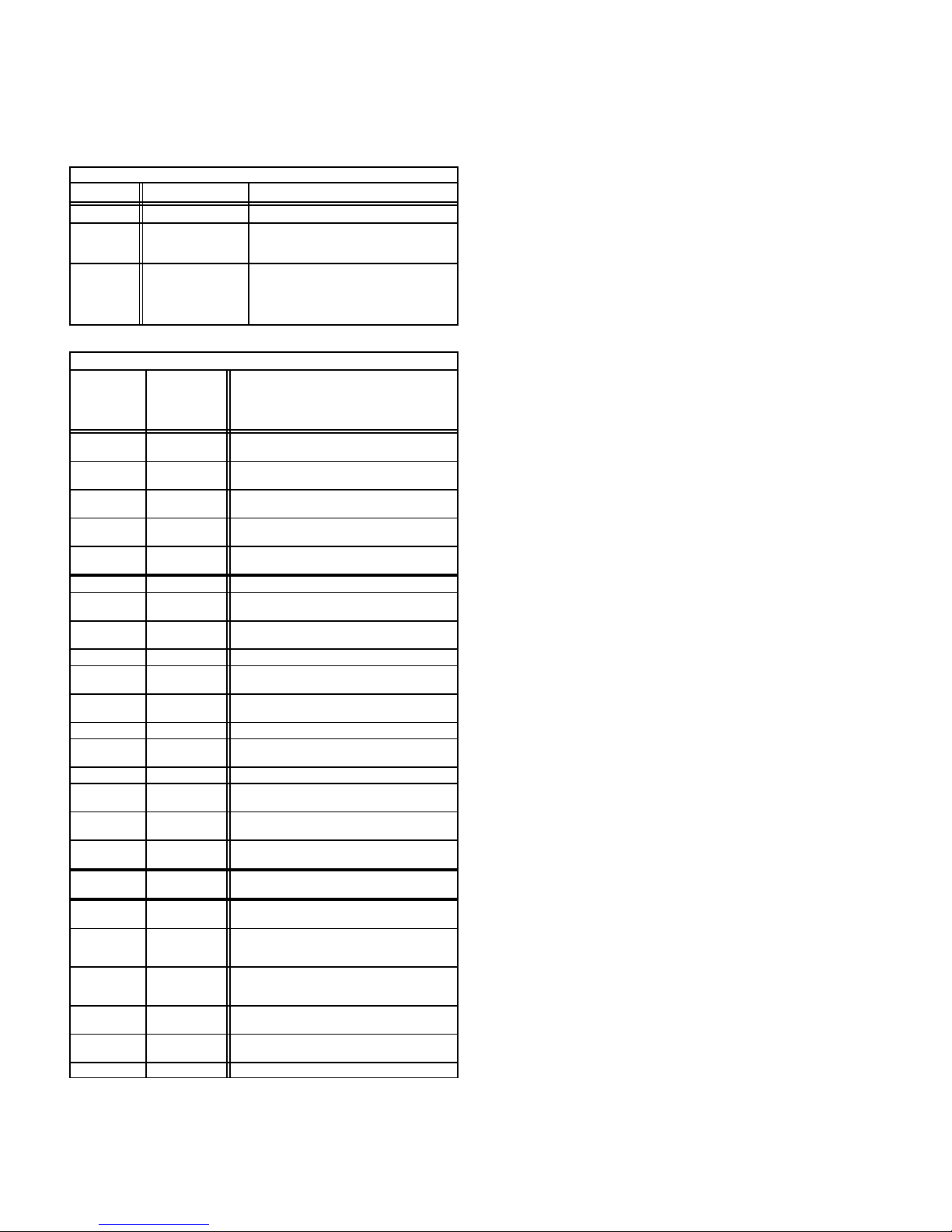
12−Ignition Control (−1 and −2 models)
G26 −1 and −2 model units use an intermittent pilot ignition
manufactured by Johnson Controls. The ignition control is
located on the upper vest panel.
Unit Operation
When there is a call for heat, the control is prevented from
beginning an ignition sequence until the pressure switch
proves combustion air blower operation. When the pressure
switch closes, the control generates a spark and opens the
pilot valve to ignite the pilot. When flame is sensed, the control opens the main gas valve and the pilot ignites the main
burners. The indoor blower starts after a 45 second delay.
Gas valve remains open and combustion air blower continues to run until demand stops, flame sensor senses loss of
flame, a limit opens or the prove switch opens. If any of these
events occur during a thermostat demand, the gas valve
closes.
The control will attempt ignition for 85 seconds. If ignition is
not successful, the control will lockout (indicated by flashing LED). Within one hour the control will momentarily remove then reapply the thermostat signal and the ignition
sequence will begin again (Watchguard circuit). If pilot
ignition is successful, but flame is lost when the main valve
opens, the ignition sequence will retry up to 15 more times.
If ignition is not successful after the 16th try, the control will
shut-down and must be reset manually. Manual reset is
accomplished by removing thermostat demand for at least
2 seconds then reapplying demand.
Table 8 shows
terminal designations.
IGNITION CONTROL A3
SPARK
OUTPUT
SEE TABLE 6
FOR TERMINAL
DESIGNATIONS
FIGURE 17
DANGER
Shock hazard. Spark related components contain
high voltage. Disconnect power before servicing.
Control is not field repairable. If control is inoperable, simply replace entire control.
Can cause injury or death. Unsafe operation will
result if repair is attempted.
TABLE 6
IGNITION CONTROL A3 TERMINAL DESIGNATIONS
Terminal Type Function
GROUND 1/4" Spade Cabinet Ground
THS 2 1/4" Spade
P. V. 1 1/4" Spade
M.V.3 1/4" Spade
SENSE 4 1/4" Spade Microamp Flame Sensing Input
Unmarked
Pin Type
Bare Wire
Safety Limit 24VAC Input
From Differential Switch
24VAC Output to Pilot Operator
24VAC Output to Main Operator
of Gas Valve
of Gas Valve
High Voltage Spark Output
Page 15
Diagnostic LED
The furnace control is equipped with a diagnostic LED
used for troubleshooting the unit and the control. LED
functions are shown in table 7.
TABLE 7
Furnace Control A3 Diagnostic LED
LED State Meaning Remedy
Steady On Normal Operation - - - Slow Flash
(1 sec. on/
5 sec. off)
Off
BLOWER CONTROL A15 TERMINAL DESIGNATIONS
Ter mi na l
(Designation
on Wiring
Diagram)
Y
G
R
W
T
IBN (N) 1/4" Spade 120VAC Indoor Blower Common
N1 (N) 1/4" Spade
CABN (N) 1/4" Spade
XFMRN(N) 1/4" Spade 120VAC Transformer Common
HSIN (N) 1/4" Spade
CAB 1/4" Spade
L1 1/4" Spade 120VAC Line Voltage In
A 1/4" Spade
XFMR 1/4" Spade 24VAC In From Transformer
D 1/4" Spade
CF 1/4" Spade
H 1/4" Spade
ACC 1/4" Spade
24V
(24)
LIMIT
(L)
W 1/4" Spade
VALV E
SENSE (V)
T 1/4" Spade
COM (C) 1/4" Spade 24VAC Common To Transformer
Control Retry
Period
Control Failure or
Power Failure or
Hard Lockout
Type Function
Detachable
Screw Strip
Detachable
Screw Strip
Detachable
Screw Strip
Detachable
Screw Strip
Detachable
Screw Strip
1/4" Spade 24VAC Input From Transformer
1/4" Spade
3/16" Spade 24VAC Input From Gas Valve
Failed to Sense Flame. Ignition Con-
If Power and Gas Supply are OK, Try
Removing T’stat Demand For At Least
30 Seconds. If LED Remains Off
When Demand Is Returned, Replace
trol Will Retry
Before Locking Out.
Control.
TABLE 8
Cooling Demand
Blower Demand
24VAC to Thermostat
Heating Demand
24VAC Common
To Indoor Thermostat
120VAC Neutral
(L2 Line Voltage Neutral)
120VAC Combustion Air Blower Com-
120VAC Hot Surface Ignition
Combustion Air Blower
to Blower Cooling Tap
Dummy Connection for
Unused Blower Leads
Continuous Blower Tap
Switched 120VAC to Accessory (Elec-
tronic Air Cleaner, Humidifier, Etc.)
24VAC In From Primary Limit. Limit
Open: Closes Gas Valve and Turns On
Blower Limit Closed: Allows Ignition
24VAC Thermostat Demand Output
Through Differential Switch to THS"
Terminal of Ignition Control
24VAC Common From
Ignition Control and Gas Valve
mon
Common (Not Used)
Switched 120VAC to
Switched 120VAC
Switched 120VAC to
Switched 120VAC to
Blower Heating Tap
Johnson G776 Ignition Control Operation
The information in this section is protected by a copyright issued by
Johnson Controls, Inc., and is reproduced with permission.
On a call for heat from indoor thermostat, the ignition control
energizes and ignition control LED lights (steady on). The
combustion air blower is energized. After 15 second prepurge period, the control simultaneously opens pilot valve
and sends spark to pilot electrode.
If pilot ignites within 85 seconds, flame sensor detects pilot
flame and signals ignition control to energize the main
valve. The main valve cannot be energized until sensor
detects pilot flame. Spark continues until pilot flame is
sensed or 85 seconds has elapsed.
When pilot flame is sensed, main valve is energized and
spark turns off. The ignition control remains in run" mode until indoor thermostat is satisfied or flame lost.
If pilot flame is not sensed before the end of the 85 second trial
for ignition, the control enters the 100% shutoff mode. The
spark circuit and pilot valve de-energize and the ignition control automatically begins the 60 minute retry delay period.
During the 60 minute delay the diagnostic LED continually
flashes on for one second and off for five seconds. After the
delay period, another trial for ignition sequence starts, beginning with pre-purge.
If pilot flame goes out while the indoor thermostat is calling
for heat, both main and pilot valves de-energize within 0.8
seconds and remain de-energized for five seconds. After
this delay, the spark and pilot valve energize until flame is
sensed or the 85 second trial for ignition period ends. If this
flameout" cycle repeats 16 times (pilot flame is established and then lost), the control locks out and the LED
goes off. A new trial for ignition sequence begins after the
thermostat contacts are opened for 2 seconds and then
closed.
If flame is detected when the thermostat calls for heat, it
must extinguish within 30 seconds for normal operation. If
flame is still present after 30 seconds, the control goes into
lockout and the LED goes off.
13−Pilot, Spark Electrode, Flame Sensor
(−1 and −2 models)
Figure 18 shows the arrangement of pilot, flame sensor,
spark electrode and burners. The ignition control uses direct spark to ignite the pilot. The pilot ignites the burners
and the burners cross-light. The flame sensor uses flame
rectification to sense pilot ignition. The ignition control requires that pilot flame must be sensed before the main gas
valve is allowed to open. Typically, a 2 to 4 second delay
occurs between the pilot ignition and the main valve opening. Figure 19 shows the gap between the tip of the electrodes and the burner surface. It is important that the gap
be maintained for consistent ignition of pilot flame.
Page 16
 Loading...