

Page 1
LENNOXOEMPARTS.COM
Service Literature
G26 SERIES UNITS
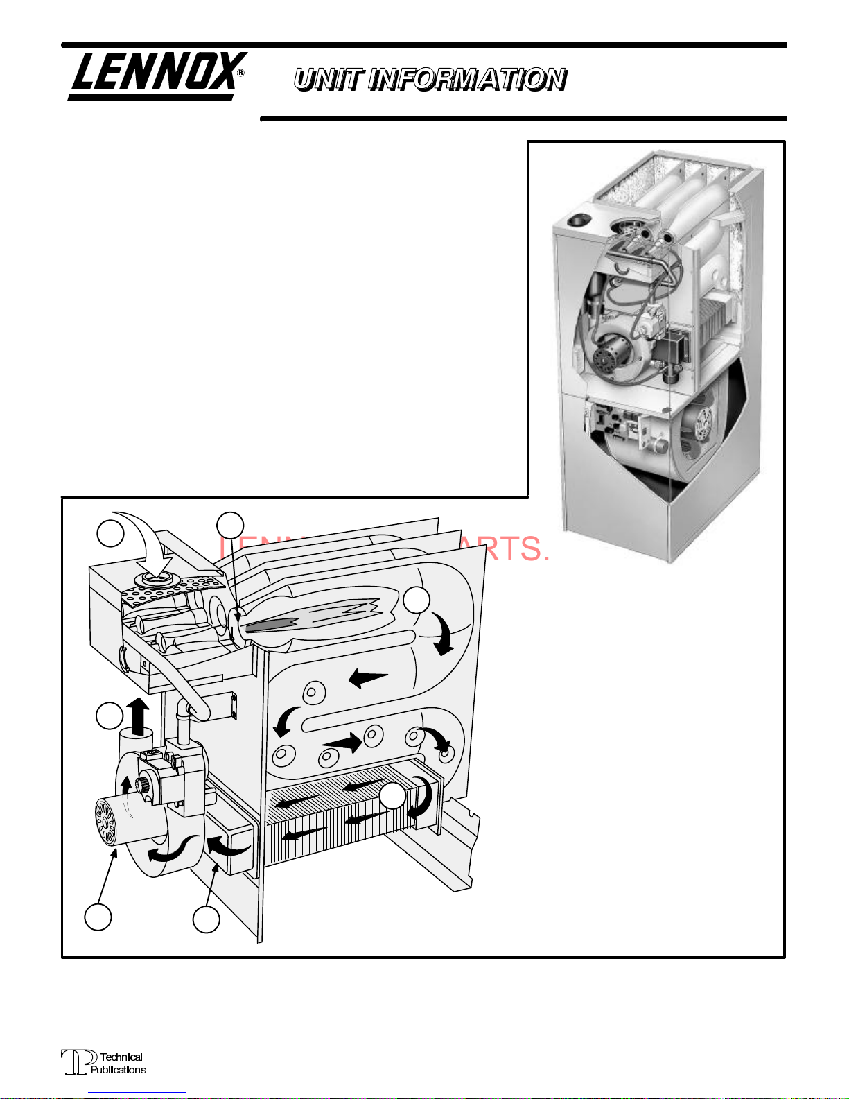
G26series unitsarehigh-efficiencyupflowgas furnacesmanufactured with
DuralokPlust aluminizedsteelclamshell-type heat exchangers. G26units
are available in heating capacities of 50,000 to 125,000 Btuh and cooling
applications upto5 tons. Refer toEngineeringHandbook for proper sizing.
Unitsare factoryequipped foruse with naturalgas. Akit isavailable forconversion to LPGoperation.G26-1 and -2model unitsuse electronic(intermittent pilot) ignition. G26-3, -4, -5 and -6 model units feature the Lennox SureLightT silicon nitrideignitionsystem.Each unitmeets theCalifornia Nitrogen Oxides (NOx) Standards and California Seasonal Efficiency requirements without modification. All units use a redundant gas valve to assure
safety shut-off as required by A.G.A. or C.G.A.
Information containedin this manualis intendedforuse byqualifiedservice
technicians only. All specifications are subject to change. Procedures outlinedin thismanual arepresented asa recommendationonly anddo notsupersede or replace local or state codes. In the absence of local or state
codes,the guidelinesand proceduresoutlined inthis manual(except where
noted) are recommended only.
G26
Corp. 9721-L11
Revised 07-2001
2
7
1
3
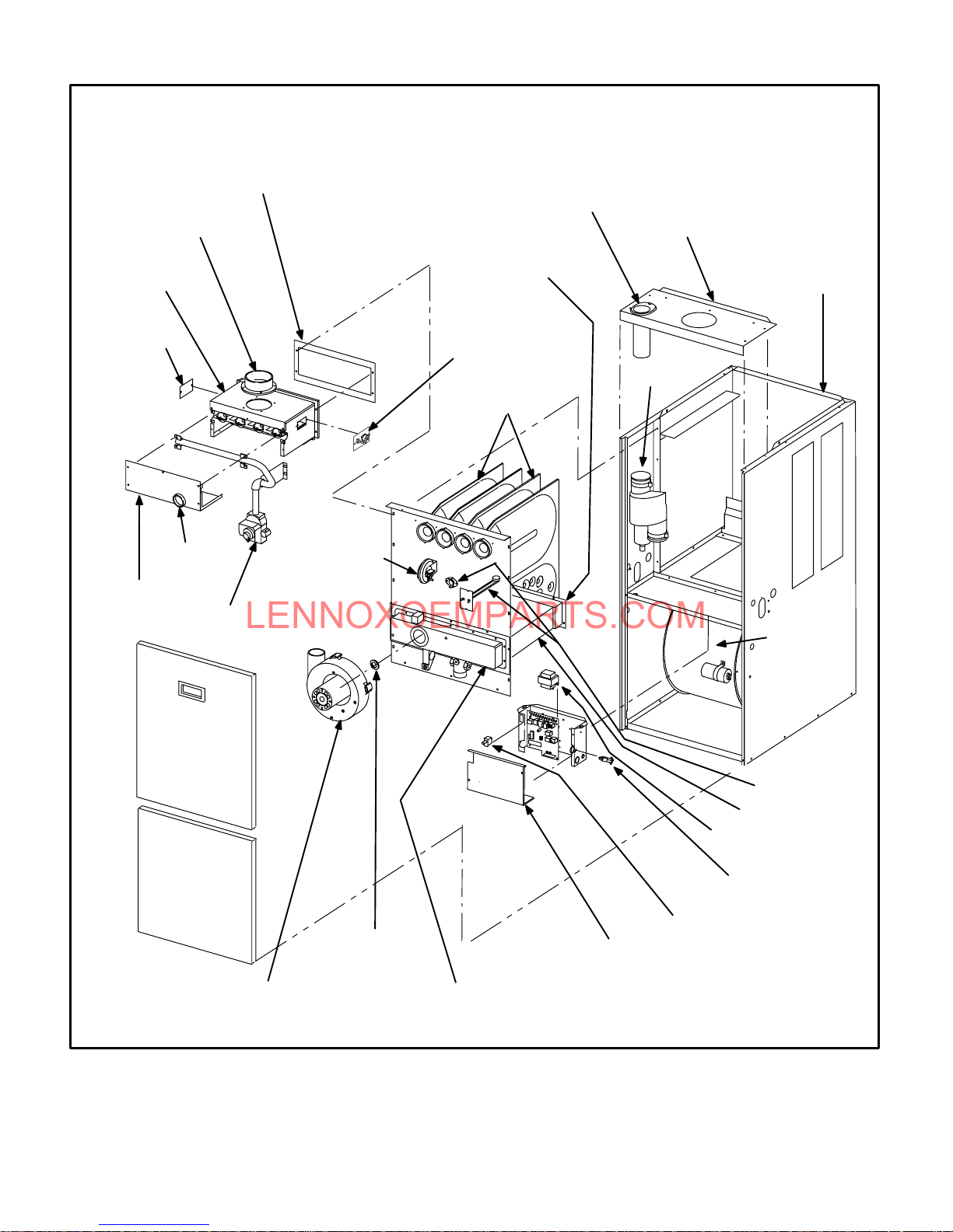
G26 FURNACEY
4
FIGURE 1
5
AG26 HEAT EXCHANGE ASSEMBLY
Combustion Process:
1. A call for heat starts the combustion air blower.
2. Outdoorairisdrawnthroughpipeintotheburner
compartment where it mixes with gas in a conventional style inshot burner.
3. TheSureLightignitionsystemlightstheburners.
4. Combustion products are drawn downward
through the heat exchanger. Heat is extracted
as indoor air passes across theoutside surface
of the metal.
5. Latent heat is removed from the combustion
productsasairpassesthroughthecoil.Condensate (water) isformed as the combustion products cool.
6. As the combustion products exit the coil, condensate is collected and drained away.
7. Combustion products are pulled from the heat
exchanger and forced into the flue.
6
Page 1
ã 1997 Lennox Industries Inc.
Litho U.S.A.
Page 2
LENNOXOEMPARTS.COM
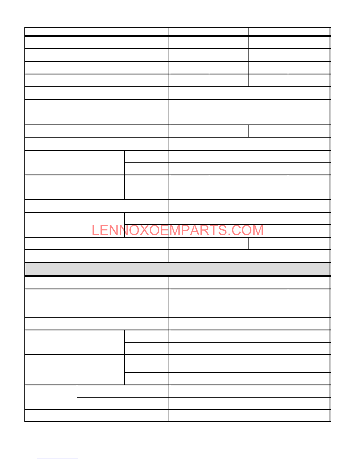
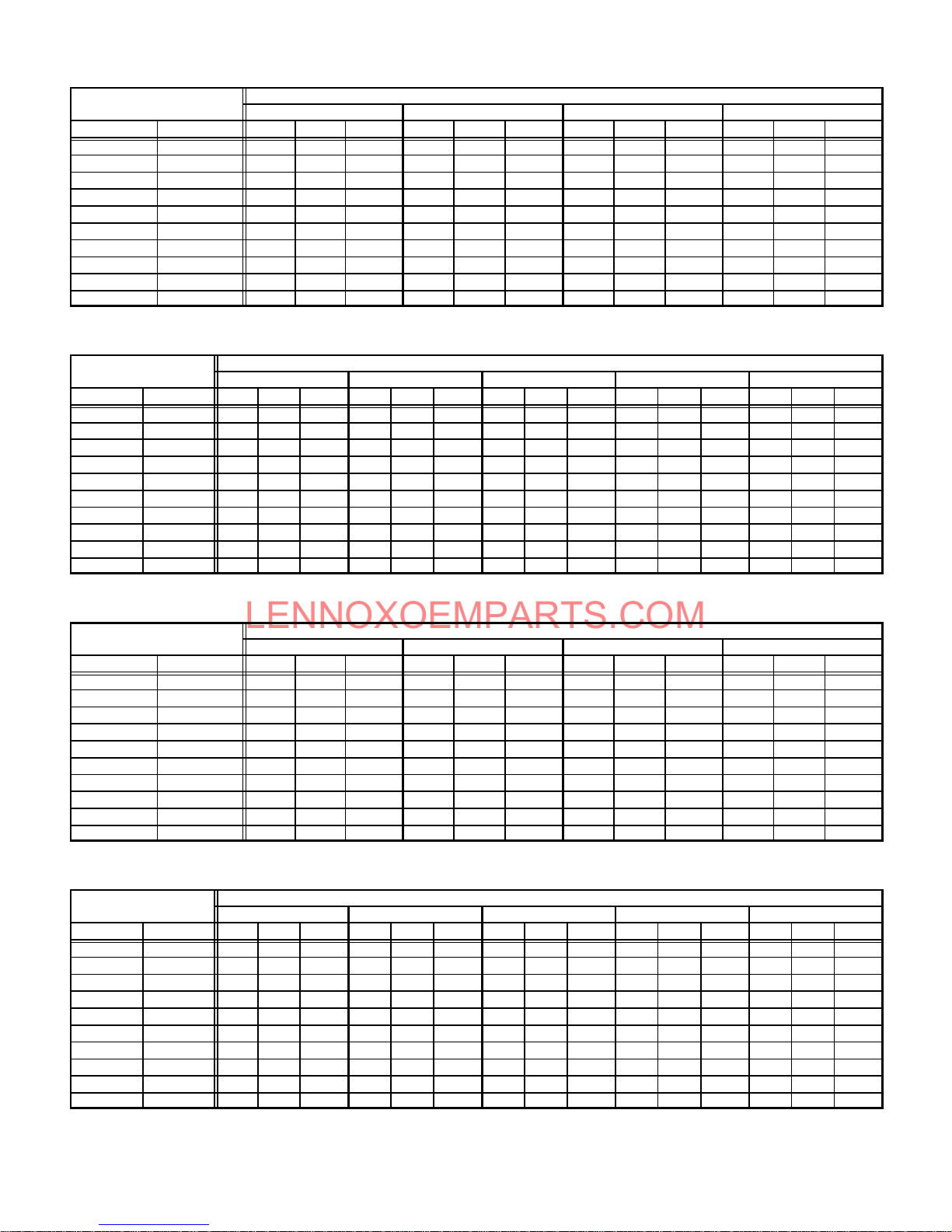
SPECIFICATIONS
GasPipingSizeI.P.S.
GasPipingSizeI.P.S.
Blowerwheelnomina
l
Blowerwheelnomina
l
Nominalcoolin
g
Nominalcoolin
g
¡
Vent/IntakeAirRoo
f
¡
Vent/IntakeAirRoo
f
15F74
(ringkit)
—
22G44
(closecouple)
—30G2
8
(WTKclosecouple
)
TerminationKit(optional)—ventsize
TwinningKit
s
TwinningKit
s
Model No. G26Q2-50 G26Q3-50 G26Q3-75 G26Q4/5-75
Input Btuh(kW) 50,000 (14.7) 75,000 (22.0)
Output Btuh (kW) 46,000 (13.5) 47,000 (13.8) 70,000(20.5) 69,000 (20.2)
lA.F.U.E. 92% 92.4% 92.0% 92.0%
California Seasonal Efficiency 85.9% 86.5% 86.3% 83.8%
¡Exhaust pipe connection (PVC) diameter— in. (mm) 2 (51)
¡Intake pipe connection (PVC) diameter— in. (mm) 2 (51)
Condensate drain connection ( PVC)— in. (mm) 1/2 (12.7)
Temperature rise range — _F (_C) 40-70 (22-39) 30-60 (17-33) 40-70 (22-39) 20-50 (11-28)
High static certified by (A.G.A./C.G.A.) — in. wg. (Pa) .50 (125)
in. 1/2
Natural orLPG/propane
diameter x width
mm 12.7
in. 10 x 7 10 x 8 11-1/2 x 9
mm 254 x 178 254 x 203 292 x 229
Blower motor output — hp (W) 1/5 (149) 1/3 (249) 3/4 (560)
Tons 1 to2 2 to 3 3-1/2 to5
that can be added
Shipping weight — lbs. (kg) 1 package 150 (68) 157 (71) 157 (71) 182 (83)
Electrical characteristics 120 volts — 60 hertz — 1 phase (all models) (less than 12 amps)
kW 3.5 to 7.0 3.5 to 10.6 12.3 to 17.6
b Optional Accessories (Must Be Ordered Extra) b
LPG/Propane kit (optional) 65K27 (all models)
Filter and Filter Rack Kits
}No. & sizeof filters - in. (mm)
Concentric Vent/Intake Air/Roof Termination Kit (optional) 60G77 — 1 1/2 inch (38 mm)
2 inch (51 mm) 15F75
Termination Kit (optional) — vent size
¡Vent/Intake Air Wall
3 inch (76 mm) 44J41
2 inch (51 mm)
Single (44J20) Ten Pack (66K61)
(1) 14 x 25 x 1 (356 x 635 x 25)
30G79 (WTKX close cou ple with extension riser)
Single (44J21)
Ten Pack (66K62)
(1) 20 x 25 x 1
(508 x 635 x 25)
3 inch (76 mm) 44J40 (close cou ple) or 81J20 (WTK close cou ple)
Non-continuous low speed 64H88 (all models)
(optional)
Continuous Low Speed Blower Switch (optional) 44J06 (-1and -2 models) N ot used with Twinning Kits
lAnnual Fuel Utilization Efficiency b ased on U.S. DOE test procedures and FT C labeling regulations. Isolated combu stion system rating for non-weatherized furnaces.
}Polyurethane frame type filter.
¡Determine fromventingtables proper intake and exhaust pipe size andtermination kitrequired.
Continuous low speed 35J93 (all models)
Page 2
Page 3
LENNOXOEMPARTS.COM
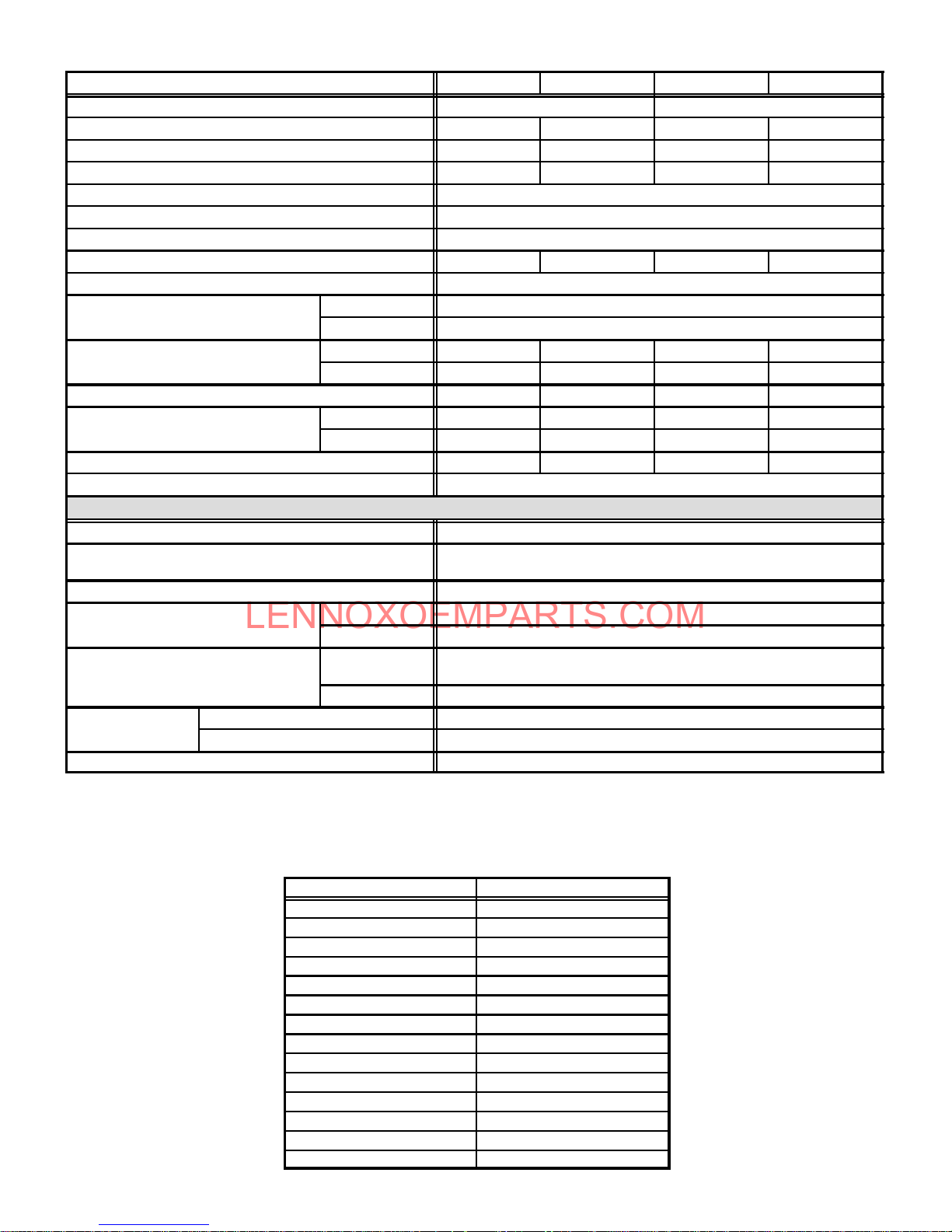
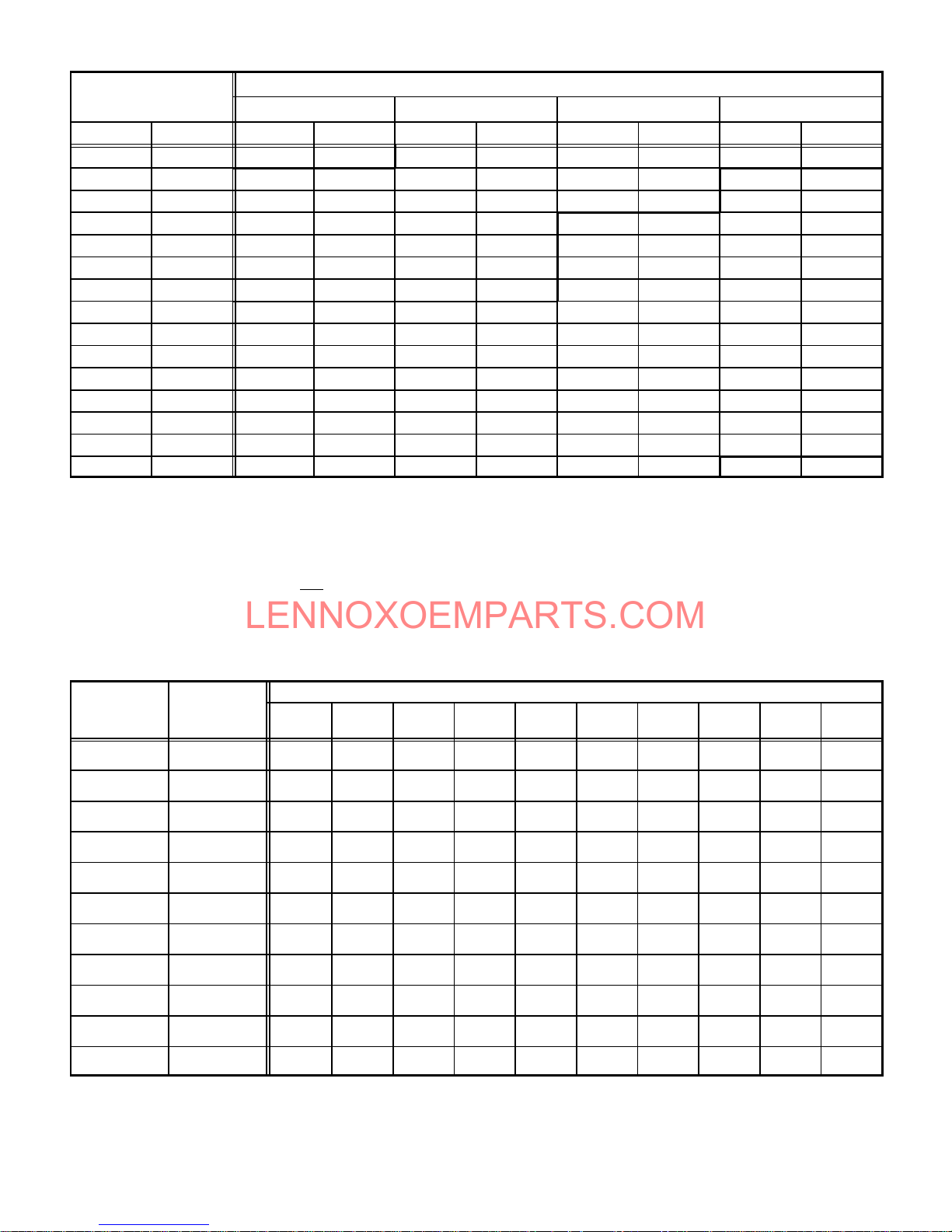
SPECIFICATIONS
GasPipingSizeI.P.S.
GasPipingSizeI.P.S.
Blowerwheelnomina
l
Blowerwheelnomina
l
Nominalcoolin
g
Nominalcoolin
g
¡
Vent/IntakeAirRoo
f
¡
Vent/IntakeAirRoo
f
TerminationKit(optional)—ventsize
TwinningKit
s
TwinningKit
s
Model No. G26Q3/4-100 G26Q4/5-100 G26Q3/4-125 G26Q4/5-125
Input Btuh (kW) 100,000 (29.3) 125,000 (36.6)
Output Btuh (kW) 91,000 (26.7) 93,000 (27.2) 115,000 ( 33.7) 116,000 (34.0)
lA.F.U.E. 92.0% 92.0% 91.0% 92.0%
California Seasonal Efficiency 86.6% 85.8% 87.5% 87.0%
¡Exhaust pipe connection (PVC) diameter— in. (mm) 2 (51)
¡Intake pipe connection (PVC) diameter— in. (mm) 3 (76)
Condensate drain connection ( PVC)— in. (mm) 1/2 (12.7)
Temperature rise range — _F (_C) 50-80 (28-44) 40-70 (22-39) 55-85 (31-47) 50-80 (28-44)
High static certified by (A.G.A./C.G.A.) — in. wg. (Pa) .50 (125)
in. 1/2
Natural orLPG/propane
diameter x width
Blower motor output — hp (W) 1/2 (373) 3/4 (560) 1/2 (373) 3/4 (560)
that can be added
Shipping weight — lbs. (kg) 1 package 186 (84) 198 (90) 218 (99) 218 (99)
Electrical characteristics 120 volts — 60 hertz — 1 phase (all models) (less than 12 amps)
LPG/Propane kit (optional) 65K27 (all models)
Filter and Filter Rack Kits
}No. & sizeof filters - in. (mm)
Concentric Vent/Intake Air/Roof Termination Kit (optional) 33K97 — 2 inch ( 51 mm)
Termination Kit (optional) — vent size
¡Vent/Intake Air Wall
Non-continuous low speed 64H88 (all models)
(optional)
Continuous Low Speed Blower Switch (optional) 44J06 (-1and -2 models) N ot used with Twinning Kits
lAnnual Fuel Utilization Efficiency b ased on U.S. DOE test procedures and FT C labeling regulations. Isolated combu stion system rating for non-weatherized furnaces.
}Polyurethane frame type filter.
¡Determine fromventingtables proper intake and exhaust pipe size andtermination kitrequired.
NOTE - 2 inch x 3 inch (51 mm x 76 mm) adaptor is furnished with -100 and -125 furnaces for exhaust pipe connection.
Continuous low speed 35J93 (all models)
mm 12.7
in. 10 x 10 11-1/2 x 9 10 x 10 11-1 /2 x 9
mm 254 x 254 292 x 229 254 x 254 292 x 229
Tons 2 to4 3-1/2 to 5 2 to 4 3- 1/2 to 5
kW 7.0 to 14.1 12.3 to17.6 7.0 to14.1 12.3 to 17.6
b Optional Accessories (Must Be Ordered Extra) b
Single (44J21) Ten Pack (66K62)
(1) 20 x 25 x 1 (508 x 635 x 25)
2 inch (51 mm) 15F75
3 inch (76 mm) 44J41
2 inch (51 mm)
3 inch (76 mm) 44J40 (close couple) — 81J20 (WTK close couple)
15F74 (ring kit) — 22G44 (close couple) — 30G28 (WTK close couple)
30G79 (WTKX close cou ple with extension riser)
BLOWER PERFORMANCE DATA
FILTER AIR RESISTANCE
cfm (L/s) in. w.g. (Pa)
0 (0) 0.00 (0)
200 (95) 0.01 (0)
400 (190) 0.03 (5)
600 (285) 0.04 (10)
800 (380) 0.06 (15)
1000 (470) 0.09 (20)
1200 (565) 0.12 (30)
1400 (660) 0.15 (35)
1600 (755) 0.19 (45)
1800 (850) 0.23 (55)
2000 (945) 0.27 (65)
2200 (1040) 0.33 (80)
2400 (1130) 0.38 (95)
2600 (1225) 0.44 (110)
Page 3
Page 4
LENNOXOEMPARTS.COM
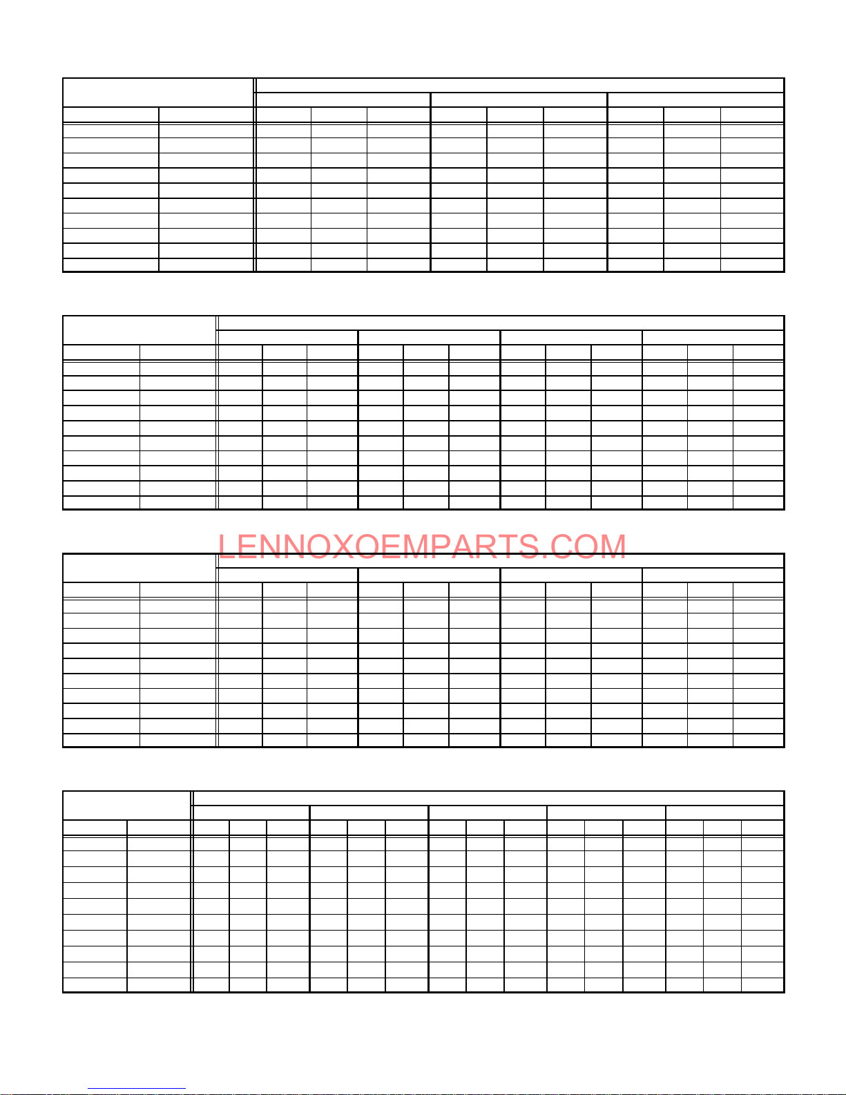
BLOWER PERFORMANCE DATA
External Static
External Static
External Static
External Static
G26Q2Ć50 BLOWER PERFORMANCE
External Static
Pressure
in. w.g. Pa cfm L/s Watts cfm L/s Watts cfm L/s Watts
0 0 1115 525 495 885 415 360 720 340 280
.10 25 1095 515 475 880 415 350 700 330 265
.20 50 1065 505 465 855 405 340 680 320 260
.30 75 1035 490 445 830 390 325 660 310 250
.40 100 995 470 425 755 355 315 645 305 235
.50 125 950 450 405 755 355 300 625 295 225
.60 150 900 425 390 740 350 280 540 255 215
.70 175 815 385 365 660 310 255 530 250 205
.80 200 610 290 340 585 275 240 360 170 180
.90 225 590 280 315 390 185 215 Ć Ć Ć Ć Ć Ć Ć Ć Ć Ć Ć Ć
NOTE Ċ All air data is measured external to unit with 1 in. (25 mm) cleanable foam filter (not furnished) in place. Also see Filter Air Resistance table.
High Medium Low
G26Q3Ć50 BLOWER PERFORMANCE
External Static
Pressure
in. w.g. Pa cfm L/s Watts cfm L/s Watts cfm L/s Watts cfm L/s Watts
0 0 1485 700 590 1275 600 485 1045 495 390 840 395 310
.10 25 1445 680 565 1250 590 460 1030 485 375 830 390 300
.20 50 1390 655 545 1225 580 445 1010 475 365 815 385 290
.30 75 1345 635 520 1190 560 425 985 465 345 790 375 285
.40 100 1290 610 500 1150 545 405 955 450 335 780 370 275
.50 125 1225 580 480 1095 515 385 920 435 315 735 345 255
.60 150 1160 545 460 1030 485 365 875 415 300 700 330 240
.70 175 1075 505 440 950 450 345 855 405 280 600 285 220
.80 200 975 460 415 865 410 315 645 305 250 510 240 195
.90 225 845 400 385 615 290 265 545 255 225 375 175 180
NOTE Ċ All air data is measured external to unit with 1 in. (25 mm) cleanable foam filter (not furnished) in place. Also see Filter Air Resistance table.
High MediumĆHigh MediumĆLow Low
Air Volume and Motor Watts at Specific Blower Taps
Air Volume and Motor Watts at Specific Blower Taps
G26Q3Ć75 BLOWER PERFORMANCE
External Static
Pressure
in. w.g. Pa cfm L/s Watts cfm L/s Watts cfm L/s Watts cfm L/s Watts
0 0 1490 705 650 1340 630 540 1060 500 440 870 410 360
.10 25 1435 675 625 1305 615 515 1050 495 425 865 410 350
.20 50 1385 655 605 1260 595 490 1025 485 405 850 400 335
.30 75 1330 630 580 1215 575 470 1000 470 385 835 395 325
.40 100 1260 595 560 1160 545 445 965 455 365 810 380 310
.50 125 1200 565 540 1100 520 420 920 435 345 770 365 290
.60 150 1125 530 515 1035 490 400 870 410 325 735 345 280
.70 175 1035 490 495 960 455 375 780 370 305 685 325 265
.80 200 935 440 475 865 410 345 725 340 285 Ć Ć Ć Ć Ć Ć Ć Ć Ć Ć Ć Ć
.90 225 805 380 445 630 295 295 540 255 240 Ć Ć Ć Ć Ć Ć Ć Ć Ć Ć Ć Ć
NOTE Ċ All air data is measured external to unit with 1 in. (25 mm) cleanable foam filter (not furnished) in place. Also see Filter Air Resistance table.
High MediumĆHigh MediumĆLow Low
Air Volume and Motor Watts at Specific Blower Taps
G26Q4/5Ć75 BLOWER PERFORMANCE
External Static
Pressure
in. w.g. Pa cfm L/s Watts cfm L/s Watts cfm L/s Watts cfm L/s Watts cfm L/s Watts
0 0 2415 1140 1240 2120 1000 1015 1875 885 855 1635 770 705 1430 675 585
.10 25 2330 1100 1200 2090 985 1005 1835 865 835 1615 760 700 1420 670 585
.20 50 2265 1070 1165 2045 965 990 1795 845 815 1580 745 690 1390 655 580
.30 75 2210 1045 1145 2000 945 970 1765 835 810 1545 730 675 1365 645 575
.40 100 2145 1010 111 0 1950 920 955 1720 810 795 1510 715 670 1340 630 570
.50 125 2075 980 1085 1885 890 930 1680 795 785 1475 695 665 1310 620 565
.60 150 2000 945 1060 1825 860 910 1630 770 770 1435 675 655 1270 600 555
.70 175 1935 915 1040 1775 840 895 1565 740 755 1395 660 645 1220 575 545
.80 200 1840 870 1005 1705 805 870 1515 715 745 1345 635 630 1165 550 535
.90 225 1760 830 980 1610 760 845 1455 685 725 1275 600 615 111 0 525 530
NOTE Ċ All air data is measured external to unit with 1 in. (25 mm) cleanable foam filter (not furnished) in place. Also see Filter Air Resistance table.
High MediumĆHigh Medium MediumĆLow Low
Air Volume and Motor Watts at Specific Blower Taps
Page 4
Page 5
LENNOXOEMPARTS.COM
BLOWER PERFORMANCE DATA
External Static
External Static
External Static
External Static
G26Q3/4Ć100 BLOWER PERFORMANCE
External Static
Pressure
in. w.g. Pa cfm L/s Watts cfm L/s Watts cfm L/s Watts cfm L/s Watts
0 0 2065 975 920 1760 830 735 1570 740 655 1245 590 520
.10 25 2000 945 875 1730 815 705 1550 730 625 1240 585 490
.20 50 1925 910 845 1685 795 675 1515 715 590 1225 580 470
.30 75 1840 870 800 1625 765 630 1475 695 565 1210 570 455
.40 100 1740 820 760 1550 730 595 1415 670 535 1165 550 430
.50 125 1650 780 730 1460 690 560 1335 630 500 1110 525 405
.60 150 1545 730 700 1370 645 530 1260 595 475 1045 495 385
.70 175 1420 670 660 1250 590 495 1170 550 445 950 450 355
.80 200 1270 600 620 1110 525 445 1025 485 395 825 390 325
.90 225 1045 495 560 965 455 405 885 420 360 700 330 290
NOTE Ċ All air data is measured external to unit with 1 in. (25 mm) cleanable foam filter (not furnished) in place. Also see Filter Air Resistance table.
High MediumĆHigh MediumĆLow Low
G26Q4/5Ć100 BLOWER PERFORMANCE
External Static
Pressure
in. w.g. Pa cfm L/s Watts cfm L/s Watts cfm L/s Watts cfm L/s Watts cfm L/s Watts
0 0 2400 1135 1255 2185 1030 1070 1940 915 905 1740 820 765 1570 740 665
.10 25 2350 111 0 1230 2150 1015 1055 1920 905 885 1710 805 755 1525 720 645
.20 50 2290 1080 1185 2105 995 1025 1875 885 865 1685 795 740 1505 710 640
.30 75 2225 1050 1170 2060 970 1005 1845 870 850 1655 780 730 1485 700 630
.40 100 2165 1020 1130 2010 950 985 1805 850 835 1620 765 720 1450 685 620
.50 125 2105 995 1115 1950 920 960 1755 830 810 1585 750 700 1415 670 605
.60 150 2040 965 1080 1895 895 940 1700 800 790 1540 725 690 1380 650 595
.70 175 1955 925 1045 1820 860 915 1640 775 775 1475 695 670 1340 630 590
.80 200 1850 875 1005 1730 815 885 1580 745 755 1430 675 660 1290 610 580
.90 225 1770 835 985 1650 780 855 1505 710 740 1370 645 645 1225 580 565
NOTE Ċ All air data is measured external to unit with 1 in. (25 mm) cleanable foam filter (not furnished) in place. Also see Filter Air Resistance table.
High MediumĆHigh Medium MediumĆLow Low
Air Volume and Motor Watts at Specific Blower Taps
Air Volume and Motor Watts at Specific Blower Taps
G26Q3/4Ć125 BLOWER PERFORMANCE
External Static
Pressure
in. w.g. Pa cfm L/s Watts cfm L/s Watts cfm L/s Watts cfm L/s Watts
0 0 2070 975 920 1735 820 725 1555 735 640 1235 585 500
.10 25 2010 950 885 1710 805 700 1535 725 625 1225 580 490
.20 50 1950 920 850 1675 790 680 1500 710 600 1210 570 470
.30 75 1975 930 820 1620 765 645 1465 690 575 1185 560 455
.40 100 1785 840 775 1560 735 615 1415 670 545 1140 540 435
.50 125 1700 800 745 1475 695 575 1345 635 520 1090 515 415
.60 150 1585 750 705 1410 665 555 1275 600 490 1035 490 390
.70 175 1475 695 675 1310 620 515 1185 560 460 975 460 370
.80 200 1350 635 640 1200 565 485 1090 515 425 865 410 340
.90 225 1200 565 595 1080 510 445 965 455 385 715 335 300
NOTE Ċ All air data is measured external to unit with 1 in. (25 mm) cleanable foam filter (not furnished) in place. Also see Filter Air Resistance table.
High MediumĆHigh MediumĆLow Low
Air Volume and Motor Watts at Specific Blower Taps
G26Q4/5Ć125 BLOWER PERFORMANCE
External Static
Pressure
in. w.g. Pa cfm L/s Watts cfm L/s Watts cfm L/s Watts cfm L/s Watts cfm L/s Watts
0 0 2400 1135 1210 2175 1025 1040 1965 925 895 1790 845 780 1610 760 670
.10 25 2315 1090 1175 2125 1005 1025 1930 910 875 1760 830 770 1580 745 660
.20 50 2255 1065 1150 2080 980 1000 1880 885 860 1740 820 755 1550 730 645
.30 75 2195 1035 1130 2030 960 975 1840 870 835 1710 805 750 1520 715 635
.40 100 2120 1000 1100 1970 930 960 1790 845 815 1665 785 730 1495 705 630
.50 125 2050 965 1080 1910 900 934 1745 825 800 1620 765 715 1460 690 620
.60 150 1985 935 1050 1840 870 905 1685 795 785 1565 740 705 1415 670 610
.70 175 1885 890 1020 1770 835 890 1635 765 775 1515 715 685 1370 645 595
.80 200 1815 855 1005 1690 800 860 1570 740 750 1450 685 670 1315 620 580
.90 225 1735 820 980 1615 760 835 1485 700 725 1385 655 655 1245 590 565
NOTE Ċ All air data is measured external to unit with 1 in. (25 mm) cleanable foam filter (not furnished) in place. Also see Filter Air Resistance table.
High MediumĆHigh Medium MediumĆLow Low
Air Volume and Motor Watts at Specific Blower Taps
Page 5
Page 6
LENNOXOEMPARTS.COM
INTAKE and EXHAUST PIPE VENTING TABLE
Nominal
Internal
Vent Pipe
Maximum
Equivalent Length
50,000 Btuh (14.7 kW) 75,000 Btuh (22.0 kW) 100,000 Btuh (29.3 kW) 125,000 Btuh (36.6 kW)
Minimum Vent Pipe Diameter Required
Feet Meters in. mm in. mm in. mm in. mm
15 4.6 1Ć1/2 38 2 51 2 51 2 51
20 6.1 2 51 2 51 2 51 3 76
25 7.6 2 51 2 51 2 51 3 76
30 9.1 2 51 2 51 3 51 3 76
40 12.2 2 51 2 51 3 51 3 76
50 15.2 2 51 2 51 3 51 3 76
55 16.8 2 51 2 51 3 76 3 76
60 18.3 3 76 3 76 3 76 3 76
70 21.3 3 76 3 76 3 76 3 76
80 24.4 3 76 3 76 3 76 3 76
90 27.4 3 76 3 76 3 76 3 76
100 30.5 3 76 3 76 3 76 3 76
110 33.5 3 76 3 76 3 76 3 76
120 36.6 3 76 3 76 3 76 3 76
130 39.6 3 76 3 76 3 76 Ć Ć Ć Ć Ć Ć Ć Ć
MINIMUM PIPE LENGTHS FOR FURNACES Ċ G26Ć50 Ċ 5 feet (1.5 m) with two 90 elbows of 1Ć1/2 inch (38 mm) diameter pipe. (15 equivalent feet (4.6 m) total).
VENTING NOTES Ċ One 90elbow is equivalent to 5 feet (1.5 m) of straight vent pipe.
Two 45 elbows are equal to one 90 elbow.
One 45 elbow is equivalent to 2.5 feet (.75 m) of straight vent pipe.
One foot (305 mm) length of 2 in. (51 mm) diameter pipe is equivalent to 8 feet (2.4 m) of 3 in. (76 mm) diameter pipe.
Intake and Exhaust pipes must
2 inch x 3 inch (51 mm x 76 mm) adaptor is furnished with Ć100 and Ć125 furnaces for exhaust pipe connection.
Exhaust pipe must terminate with 1Ć1/2 inch (38 mm) diameter pipe for furnaces using1Ć1/2 (38 mm) or 2 inch (51 mm) diameter pipe runs.
Exhaust pipe must terminate with 2 inch (51 mm) diameter pipe for furnaces using 3 inch (76 mm) diameter pipe runs.
See pages 10 thru 12 for Termination Kits available.
G26Ć75 Ċ 5 feet (1.5 m) with two 90 elbows of 2 inch (51 mm) diameter pipe. (15 equivalent feet (4.6 m) total).
G26Ć100 Ċ 5 feet (1.5 m) with two 90 elbows of 2 inch (51 mm) diameter pipe. (15 equivalent feet (4.6 m) total).
G26Ć125 Ċ 5 feet (1.5 m) with two 90 elbows of 2 inch (51 mm) diameter pipe. (15 equivalent feet (4.6 m) total).
be the same diameter.
GAS PIPE CAPACITY - FT3/HR (kL/HR)
Nominal Internal
Iron Pipe Size
-Inches(mm)
1/4
(6.35)
3/8
(9.53)
1/2
(12.7)
3/4
(19.05)
1
(25.4)
1-1/4
(31.75)
1-1/2
(38.1)
2
(50.8)
2-1/2
(63.5)
3
(76.2)
4
(101.6)
Diameter
-Inches(mm)
.364
(9.246)
.493
(12.522)
.622
(17.799)
.824
(20.930)
1.049
(26.645)
1.380
(35.052)
1.610
(40.894)
2.067
(52.502)
2.469
(67.713)
3.068
(77.927)
4.026
(102.260)
10
(3.048)20(6.096)30(9.144)40(12.192)50(15.240)60(18.288)70(21.336)80(24.384)90(27.432)
43
(1.13)
95
(2.69)
175
(4.96)
360
(10.19)
680
(19.25)
1400
(39.64)
2100
(59.46)
3950
(111.85)
6300
(178.39)
11000
(311.48)
23000
(651.27)
29
(.82)
65
(1.84)
120
(3.40)
250
(7.08)
465
(13.17)
950
(26.90)
460
(41.34)
2750
(77.87)
4350
(123.17)
7700
(218.03)
15800
(447.39)
24
(.68)
52
(1.47)
97
(2.75)
200
(5.66)
375
(10.62)
770
(21.80)
1180
(33.41)
2200
(62.30)
3520
(99.67)
6250
(176.98)
12800
(362.44)
NOTE-Capacity given in cubic feet of gas per hour (kilo liters of gas per hour) and based on 0.60 specific gravity gas.
Length of Pipe-Feet(m)
20
(.57)
45
(1.27)
82
(2.32)
170
(4.81)
320
(9.06)
660
(18.69)
990
(28.03)
1900
(53.80)
3000
(84.95)
5300
(150.07)
10900
(308.64)
18
(.51)
40
(1.13)
73
(2.07)
151
(4.28)
285
(8.07)
580
(16.42)
900
(25.48)
1680
(47.57)
2650
(75.04)
4750
(134.50)
9700
(274.67)
16
(.45)
36
(1.02)
66
(1.87)
138
(3.91)
260
(7.36)
530
(15.01)
810
(22.94)
1520
(43.04)
2400
(67.96)
4300
(121.76)
8800
(249.18)
15
(.42)
33
(.73)
61
(1.73)
125
(3.54)
240
(6.80)
490
(13.87)
750
(21.24)
1400
(39.64)
2250
(63.71)
3900
(110.43)
8100
(229.36)
14
(.40)
31
(.88)
57
(1.61)
118
(3.34)
220
(6.23)
460
(13.03)
690
(19.54)
1300
(36.81)
2050
(58.05)
3700
(104.77)
7500
(212.37)
13
(.37)
29
(.82)
53
(1.50)
110
(3.11)
205
(5.80)
430
(12.18)
650
(18.41)
1220
(34.55)
1950
(55.22)
3450
(97.69)
7200
(203.88)
100
(30.480)
12
(.34)
27
(.76)
50
(1.42)
103
(2.92)
195
(5.52)
400
(11.33)
620
(17.56)
1150
(32.56)
1850
(52.38)
3250
(92.03)
6700
(189.72)
Page 6
Page 7
LENNOXOEMPARTS.COM
GLASS FIBER GASKET
FRESH AIR
INTAKE FITTING
BURNER BOX
ASSEMBLY
PATCH
PLATE
G26-3 THROUGH -6 COMPONENTS
FLUE COLLAR
WARM
HEADER
(COLLECTOR)
BOX
PATCH PLATE WITH
BARBED FITTING
AND FLAME
ROLL-OUT SWITCH
DuralokPlus
HEAT EXCHANGER
ASSEMBLY
TM
TOP CAP
CABINET
FLUE
TRANSITION
FLAME SIGHT
BURNER
BOX
COVER
GLASS
GAS VALVE AND
MANIFOLD
BURNER
ACCESS
PANEL
BLOWER
ACCESS
DOOR
COMBUSTION AIR
BLOWER
COMBUSTION AIR
PROVE (PRESĆ
SURE) SWITCH
COMBUSTION AIR
ORIFICE
COLD HEADER
(COLLECTOR)
BOX
CONTROL TRANSFORMER
DOOR INTERLOCK
CONTROL BOX COVER
SUPPLY
AIR
BLOWER
PRIMARY LIMIT
(ALTERNATE STYLES)
CONDENSER COIL
CONTROL VOLTĆ
AGE
CIRCUIT BREAKER
SWITCH
FIGURE 1
Page 7
Page 8
LENNOXOEMPARTS.COM
BURNER
ACCESS
COVER
BURNER BOX
MANIFOLD
GAS VALVE
FRESH AIR INTAKE
FITTING
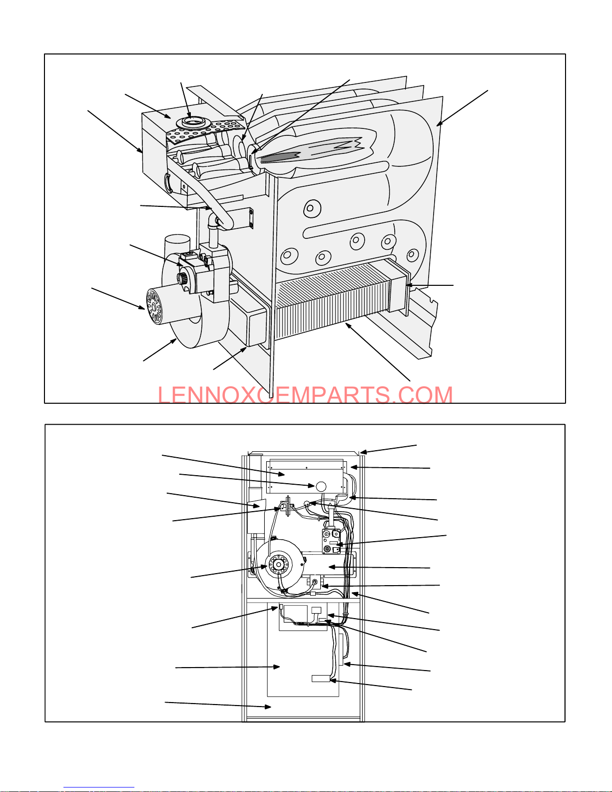
G26 HEAT EXCHANGER
CORBEL ORIFICE
CUPS
SURELIGHT IGNITOR LENNOX DURALOKPLUS
HEAT EXCHANGER ASĆ
SEMBLY
COMBUSTION AIR
BLOWER MOTOR
COMBUSTION
AIR BLOWER
BURNER
FLAME SIGHT GLASS
FLUE TRANSITION
DIFFERENTIAL
(COMBUSTION AIR)
PRESSURE SWITCH
BOX
COLD HEADER
(COLLECTOR )
BOX
FIGURE 2
G26 GENERAL PARTS ORIENTATION
WARM HEAD
(COLLECTOR)
BOX
CONDENSER COIL
SUPPLY AIR DUCT
FLANGE
UPPER VEST PANEL
GAS MANIFOLD
PRIMARY LIMIT
GAS VALVE
COMBUSTION AIR BLOWER
DOOR INTERLOCK
SWITCH
BLOWER HOUSING
BLOWER
COMPARTMENT
FIGURE 3
COLD HEADER BOX
HEADER BOX
CONDENSATE
TRAP
LOWER VEST PANEL
CONTROL BOX
CIRCUIT BREAKER
BLOWER MOTOR
BLOWER MOTOR CAPACITOR
Page 8
Page 9
LENNOXOEMPARTS.COM
OUTSIDE INSTALLATION
MAKEĆUP BOX
MAKEĆUP BOX INSTALLATION
Box may be installed inside or outside cabinet and may
be installed on left side or right side of cabinet
STAR WASHERS
MUST BREAK
PAINT ON UNIT
CABINET FOR
PROPER
GROUND.
UNIT
CABINET
INSIDE INSTALLATION
MAKEĆUP BOX
Line Voltage Enters Through
Knockout In MakeĆUp Box. J69
Passes Through Side Knockout
Into Side Of Unit.
JACK J69
BLOWER MULLION
PLUG P69
FIGURE 4
I-UNIT COMPONENTS
G26 unit components are shown in figure 1. General parts oriĆ
entation is shown in figure 3. The gas valve, ignition control
and burners can be accessed by removing the burner access
panel. The blower and blower controls can be accessed by
removing the blower access door.
G26 units are designed for bottom and side return air. The
panels are designed to be knockedĆout (bottom return) or
cutĆout (side return) as required for return air duct connecĆ
tion.
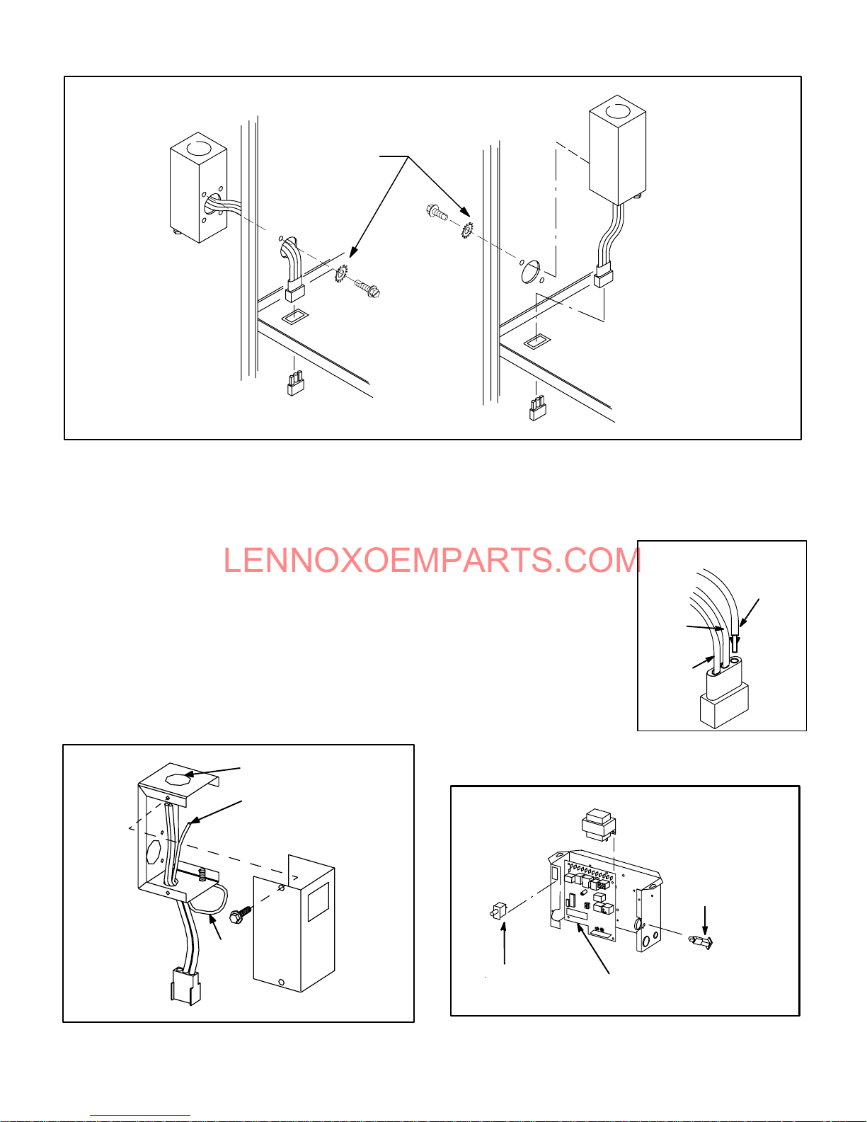
A-MakeĆUp Box (Figure 5)
The line voltage makeĆup box is shown in figure 5. The box
may be installed inside or outside the unit and may be
installed on the unit left or right side (figure 4).
MAKEĆUP BOX
BOX
POWER ENTRY KNOCKOUT
120V LINE VOLTAGE
PIGTAIL CONNECTIONS
COVER
Line Voltage Enters MakeĆUp
Box Through Side Of Unit and
J69 Passes Through Bottom
Knockout in MakeĆUp Box.
BLOWER MULLION
An accessory (brown) output wire is provided with the makeĆ
up box. The wire provides a 120V connection for optional acĆ
cessories such as electronic air cleaner or humidifier. If used,
the wire is field installed in J69 jack plug by inserting the pin
of the brown wire into the open
socket of the jack. See figure
6. 120V accessories rated up
to 4 amps total may be conĆ
nected to this wire. The neutral
leg of the accessory is conĆ
INSTALLING BROWN
ACCESSORY WIRE TO J69
BROWN
WHITE
NEUTRAL
nected to the neutral white
wire in the makeĆup box. The
accessory terminal is enerĆ
gized whenever the blower is
in operation.
BLACK
J69
FIGURE 6
B-Control Box Components
G26 CONTROL BOX
TRANSFORMER
UNIT
GROUND
JACK J69
to blower deck
Box may be installed inside or outside unit. See Figure 4
TO BLOWER MULLION
FIGURE 5
Page 9
DOOR
INTERLOCK
SWITCH
SURELIGHT CONTROL
(-3 through -6 models )
FIGURE 7
CIRCUIT
BREAKER
Page 10
LENNOXOEMPARTS.COM
Electrical blower control components (A15), unit transformĆ
er (T1) and 24V circuit breaker (CB8) are located in the conĆ
trol box. In addition, a door interlock switch (S51) is located
in the control box. Jackplugs and a snapĆoff" terminal strip
allow the control box to be easily removed for blower serĆ
vice.
1- Control Transformer (T1)
A transformer located in the control box provides power to
the low voltage 24volt section of the unit. Transformers on
all models are rated 40VA with a 120V primary and a 24V
secondary.
2- Circuit Breaker (CB8)
A 24V circuit breaker is also located in the control box. The
switch provides overcurrent protection to the transformer
(T1). The breaker is rated 3A at 32V. If the current exceeds
this limit the breaker will trip and all unit operation will shutĆ
down. The breaker can be manually reset by pressing the
button on the face.
3-Door Interlock Switch (S51)
A door interlock switch rated 14A at 125VAC is located on
the control box. The switch is wired in series with line voltĆ
age. When the blower door is removed the unit will shut
down.
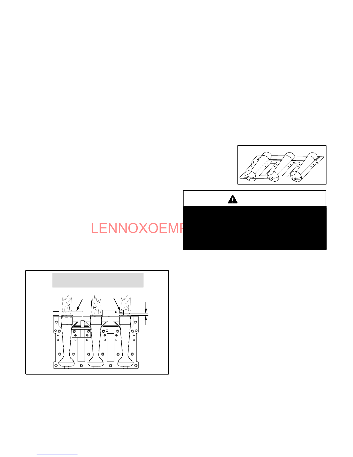
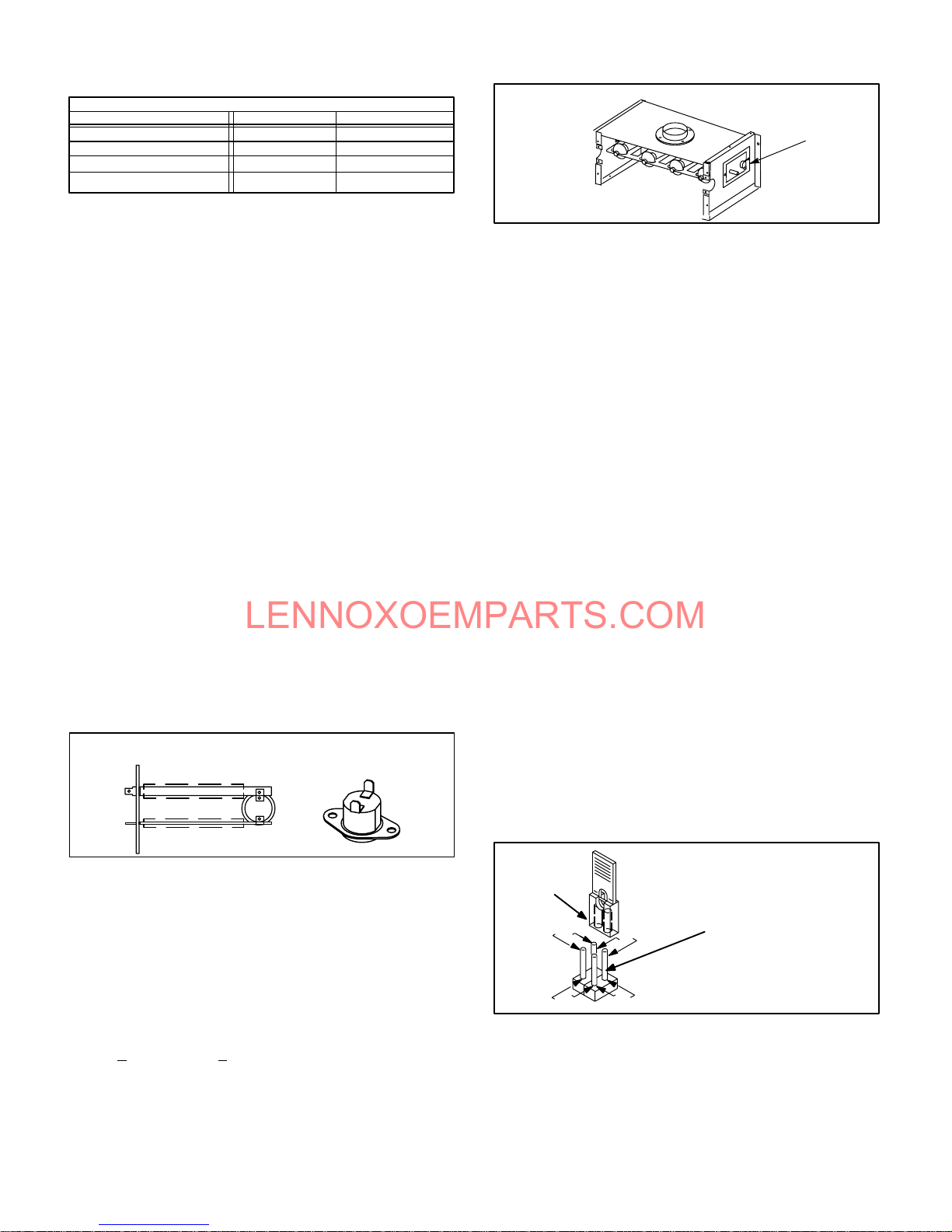
4-Flame Sensor (-3 through -6 models)
A flame sensor is located on the left side of the burner supĆ
port. See figure 8. The sensor is mounted on a bracket in
the burner support and the tip protrudes into the flame enĆ
velope of the left-most burner. The sensor is fastened to
burner supports and can be removed for service without
removing any part of the burners. During operation, flame
is sensed by current passed through the flame and sensĆ
ing electrode. The SureLight control allows the gas valve
to remain open as long as flame signal is sensed.
NORMAL FLAME SIGNAL u 0.7 MICROAMPS
LOW FLAME SIGNAL v 0.7 MICROAMPS
MINIMUM FLAME SIGNAL v 0.15 MICROAMPS
SENSOR
3/8"
FIGURE 8
NOTE - The G26 furnace contains electronic compoĆ
nents that are polarity sensitive. Make sure that the
furnace is wired correctly and is properly grounded.
IGNITOR
5/16"
5-Burners
All units use inshot burners (see figure 9). Burners are factory
set and do not require adjustment. A sigh t gl as s is furĆ
nished in the burner box assembly for flame viewing. AlĆ
ways operate the unit with the burner box cover in place.
Burners can be removed as an assembly for service. Burner
maintenance and service is detailed in the MAINTENANCE
section of this manual. Each burner uses an orifice which is
precisely matched to the burner input (see nameplate for
orifice size). The orifice is threaded into the burner manĆ
ifold. The burner is supported by the orifice and will easily
slide off for service. Each orifice and burner are sized speĆ
cifically to the unit. Refer to Lennox Repair Parts Listing for
correct sizing information. A flame retention ring in the end of
each burner maintains correct flame length and shape and
keeps the flame from lifting off the burner head. In addition,
the burner entrance to each clamshell (Figure 2) is fitted with
a corbel cup (orifice)
used to direct the
flow of combustion
products.
TYPICAL BURNER ASSEMBLY
FIGURE 9
DANGER
Shock hazard.
Disconnect power before servicing. Control is not
field repairable. If control is inoperable, simply
replace entire control.
Can cause injury or death. Unsafe operation will
result if repair is attempted.
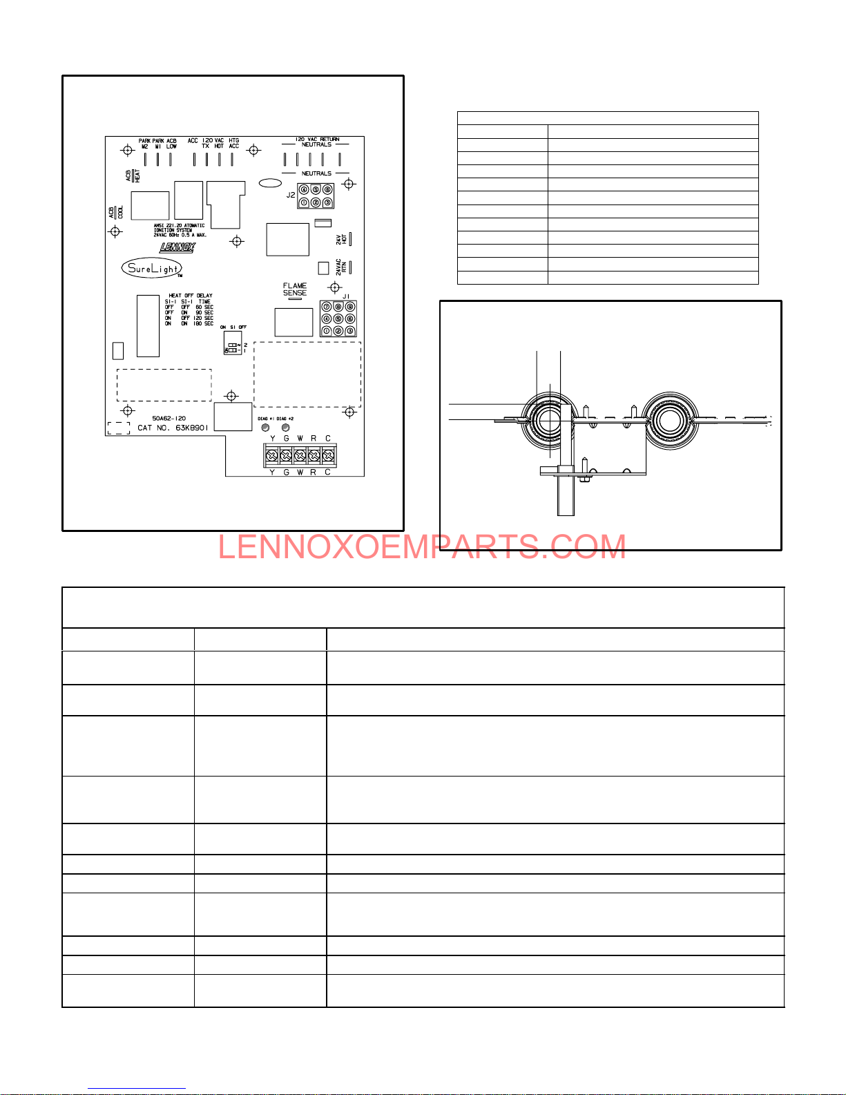
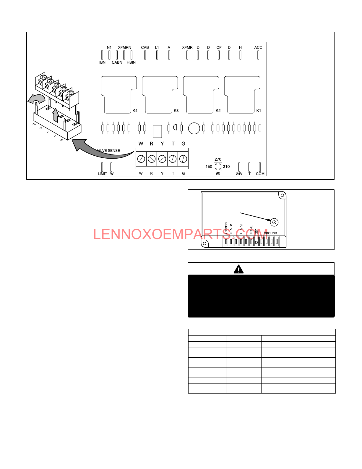
6- SureLight Ignition System A3
(-3 through -6 models)
All G26-3 through -6 model units are equipped with the
Lennox Sure - Light ignition system. The system consists
of ignition control board (figure 10 with control terminal
designations in table 1) and ignitor (figures 8 and 11). The
board and ignitor work in combination to ensure furnace
ignition and ignitor durability. The SureLight integrated
board controls all major furnace operations. The board
also features two LED lights for troubleshooting and two
accessory terminals rated at (4) four amps. See table 2
for troubleshooting diagnostic codes. Table 3 and 4 show
jack plug terminal designations. Units equipped with the
SureLight board can be used with either electronic or
electro-mechanical thermostats without modification.
The SureLight ignitor is made of durable silicon-nitride.
Ignitor longevity is also enhanced by voltage ramping by
the control board. The board finds the lowest ignitor temĆ
perature which will successfully light the burner, thus inĆ
creasing the life of the ignitor.
NOTE - Do not remove blower access panel to read
SureLight LED lights. A sight glass is provided on the
access panel for viewing.
Page 10
Page 11
LENNOXOEMPARTS.COM
SURELIGHT CONTROL BOARD
TABLE 1
SURELIGHT CONTROL TERMINAL DESIGNATIONS
ACB COOL
ACB HEAT
PARK
ACB LOW
ACC
TX
HOT
HTG ACC
NEUTRALS
24VAC HOT
24VAC RTN
FLAME SENSE
Blower - Cooling Speed (Line Volt)
Blower - Heating Speed (Line Volt)
Alternate Blower Speeds (Dead)
Continuous Low Speed Blower
Accessory Terminal (Line Volt)
120VAC Hot to Transformer
120VAC Hot Input
Heat Only Accessory (Line Volt)
120VAC Neutrals
24VAC Hot from Transformer
24VAC Return from Transformer
Flame Sense Terminal
SURELIGHT IGNITOR
MEASUREMENT IS TO I.D.
5/8"
OF RETENTION RING
13/32'
FIGURE 10
FIGURE 11
TABLE 2
DIAGNOSTIC CODES
MAKE SURE TO ID LED'S CORRECTLY: REFER TO INSTALLATION INSTRUCTIONS FOR CONTROL BOARD LAYOUT.
LED #1 LED #2 DESCRIPTION
SIMULTANEOUS
SLOW FLASH
SIMULTANEOUS FAST
FLASH
SIMULTANEOUS
SLOW FLASH
SIMULTANEOUS FAST
FLASH
Also signaled during cooling and continues fan.
Normal operation - signaled when heating demand initiated at thermostat.
Primary or Secondary limit open. Units with board 63K8901 or 24L85: Limit must
SLOW FLASH ON
close within 5 trials for ignition or board goes into one hour limit Watchguard.
Units with board 56L83 or 97L48: Limit must close within 3 minutes or board
Pressure switch open or has opened 5 times during a single call for heat; OR:
OFF SLOW FLASH
Blocked inlet/exhaust vent; OR: Condensate line blocked; OR: Pressure switch
closed prior to activation of combustion air blower.
ALTERNATING SLOW
FLASH
SLOW FLASH OFF
ON SLOW FLASH
ON
ON
OFF
FAST FLASH SLOW FLASH
SLOW FLASH FAST FLASH
ALTERNATING FAST
FLASH
NOTE - Slow flash equals 1 Hz (one flash per second). Fast flash equals 3 Hz (three flashes per second). Drop out flame sense current < 0.15 microAmps
ALTERNATING SLOW
FLASH
ON
OFF
ON
ALTERNATING FAST
FLASH
Flame sensed without gas valve energized.
Rollout switch open. OR: 9 pin connector improperly attached.
Circuit board failure or control wired incorrectly.
Main power polarity reversed. Switch line and neutral.
Low flame signal. Measures below .7 microAmps. Replace flame sense rod.
Improper main ground or line voltage below 75 volts; OR: Broken ignitor; OR:
Power - Normal operation
goes into one hour limit Watchguard.
Watchguard - burners fail to ignite.
Open ignitor circuit.
Page 11
Page 12
LENNOXOEMPARTS.COM
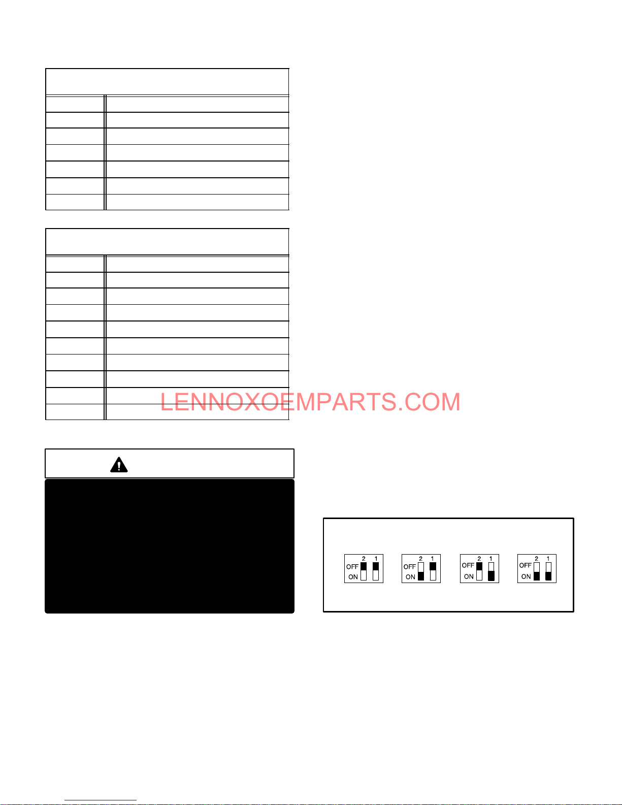
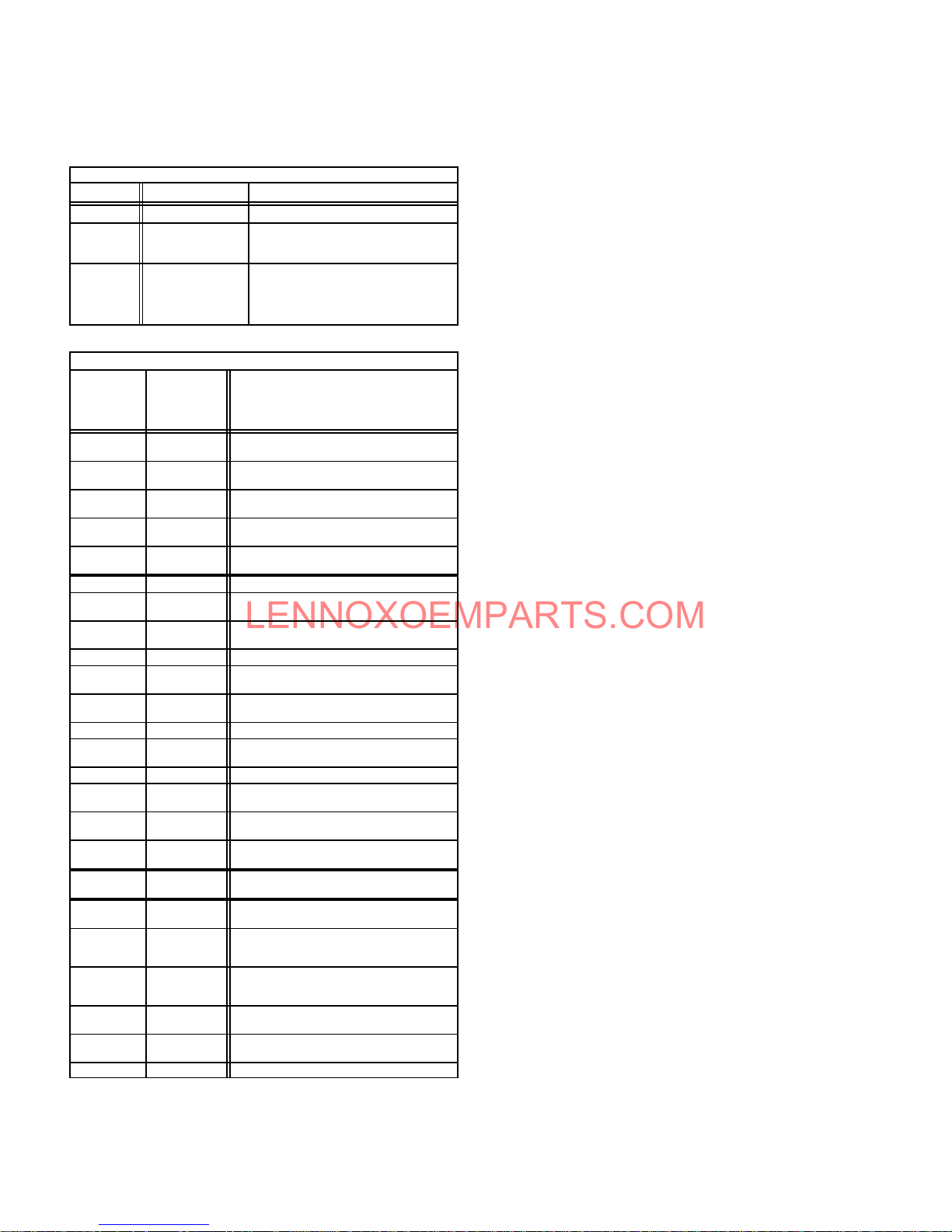
TABLE 3
SureLight BOARD J156 (J2) TERMINAL
PIN # FUNCTION
1 Ignitor
2
3
4
5
6
DESIGNATIONS
Not Used
Ignitor Neutral
Combustion Air Blower Line Voltage
Not Used
Combustion Air Blower Neutral
TABLE 4
SureLight BOARD J58 (J1) TERMINAL
PIN # FUNCTION
1 Primary Limit In
2
3
4
5
6
7
8
9
DESIGNATIONS
Gas Valve Common
Roll Out Switch Out
Gas Valve 24V
Pressure Switch In
Pressure Switch and Primary Limit Out
Not Used
Roll Out Switch In
Ground
ELECTROSTATIC DISCHARGE (ESD)
Precautions and Procedures
CAUTION
Electrostatic discharge can affect electronic
components. Take precautions during furnace
installation and service to protect the furnace's
electronic controls. Precautions will help to
avoid control exposure to electrostatic disĆ
charge by putting the furnace, the control and
the technician at the same electrostatic potenĆ
tial. Neutralize electrostatic charge by touching
hand and all tools on an unpainted unit surface,
such as the gas valve or blower deck, before perĆ
forming any service procedure.
a-Electronic Ignition
On a call for heat the SureLight control monitors the comĆ
bustion air blower pressure switch. The control will not beĆ
gin the heating cycle if the pressure switch is closed (bypassed). Once the pressure switch is determined to be
open, the combustion air blower is energized. When the
differential in the pressure switch is great enough, the
pressure switch closes and a 15-second pre-purge beĆ
gins. If the pressure switch is not proven within 2-1/2 minĆ
utes, the control goes into Watchguard-Pressure Switch
mode for a 5-minute re-set period.
After the 15-second pre-purge period, the SureLight igniĆ
tor warms up for 20 seconds after which the gas valve
opens for a 4-second trial for ignition. G26 units with board
63K89, 24L85 or 56L83: the ignitor stays energized for the
first second of the 4-second trial. Units with board 97L48:
ignitor stays energized for the full 4-second ignition trial. If
ignition is not proved during the 4-second period, the conĆ
trol will try four more times with an inter purge and warm-up
time between trials of 35 seconds. After a total of five trials
for ignition (including the initial trial), the control goes into
Watchguard-Flame Failure mode. After a 60-minute reset
period, the control will begin the ignition sequence again.
The SureLight control board has an added feature that
prolongs the life of the ignitor. After a successful ignition,
the SureLight control utilizes less power to energize the igĆ
nitor on successive calls for heat. The control continues to
ramp down the voltage to the ignitor until it finds the lowest
amount of power that will provide a successful ignition.
This amount of power is used for 255 cycles. On the 256th
call for heat, the control will again ramp down until the lowĆ
est power is determined and the cycle begins again.
b-Fan Time Control
The fan on time of 45 seconds is not adjustable. Fan off
time (time that the blower operates after the heat demand
has been satisfied) can be adjusted by flipping the dip
switches located on the SureLight integrated control. The
unit is shipped with a factory fan off setting of 90 seconds.
Fan off time will affect comfort and is adjustable to satisfy
individual applications. See figure 12.
FANĆOFF TIME ADJUSTMENT
60sec. 90sec. 120sec. 180sec.
To adjust fan-off timing, flip dip switch to desired setting.
FIGURE 12
7-Blower Motors and Capacitors
All G26 units use direct drive blower motors. All motors
used are 120V permanent split capacitor motors to ensure
maximum efficiency. See table 5 for ratings.
Page 12
Page 13
LENNOXOEMPARTS.COM
TABLE 5
BLOWER MOTOR HP
G26Q2
G26Q3
G26Q3/4
G26Q4/5
G26 BLOWER RATINGS 120V 1PH
1/5
1/3
1/2
3/4 40MFD 370V
CAP
5MFD 370V
5MFD 370V
7.5MFD 370V
8-Combustion Air Blower (B6)
All G26 units use a combustion air blower to move air
through the burners and heat exchanger during heating opĆ
eration. The blower uses a PSC or shaded Pole 120VAC
motor. PSC motors use run capacitors. The motor operates
during all heating operation and is controlled by blower conĆ
trol A15. The blower operates continuously while there is a
call for heat. The ignition control is prevented from proceedĆ
ing through the ignition sequence until combustion air blower
operation is sensed by the prove switch.
The pressure switch connected to the combustion air blower
housing is used to prove combustion air blower operation.
The switch monitors air pressure in the blower housing. DurĆ
ing normal operation, the pressure in the housing is negaĆ
tive. If the pressure drops (becomes more positive), the
pressure switch opens. When the pressure switch opens,
the ignition control (A3) immediately closes the gas valve to
prevent burner operation.
9-Primary Limit Control (S10)
The primary limit (S10) on G26 units is located in the
middle of the heating vestibule panel. When excess heat
is sensed in the heat exchanger, the limit will open. If the
limit is tripped, the furnace control energizes the supply air
blower and de-energizes the gas valve. The limit automatiĆ
cally resets when unit temperature returns to normal. The
switch is factory set and cannot be adjusted. The switch
may have a different setpoint for each unit model numĆ
ber. However, the setpoint will be printed on the side of
the limit.
SPADE CONNECTORS
G26 SERIES UNITS AND ALTERNATE STYLE
LIMIT CONTROL (S10) FOR
Units may be equipped with either style limit.
LIMIT
INSULATING COVER (s)
FIGURE 13
10-Rollout Switch (S47) -3 Through -6
Flame rollout switch S47 is a SPST N.C. high temperature
limit located on the right side of the burner box assembly (see
figure 14). S47 is wired to the burner ignition control A3.
When S47 senses flame rollout (indicating a blockage
in the combustion passages), the flame rollout switch
trips, and the ignition control immediately closes the
gas valve.
Switch S47 in all G26 units is factory preset to open at
200F + 12F (93C + 6.7C) on a temperature rise. All
flame rollout switches are manually reset. A kit (#65K60) is
available for G26 -1 and -2 models.
FLAME ROLLOUT SWITCH (S47)
FLAME ROLLOUT
SWITCH (S47)
FIGURE 14
11- BCC2-3 Blower Control A15
(-1 and -2 models)
All G26-2 and -1 model units utilize the BCC2Ć3 blower conĆ
trol manufactured by Heatcraft. The BCC2Ć3 is a printed cirĆ
cuit board which controls the supply air blower and monitors
primary limit and gas valve operation. The control has a
nonĆadjustable, factory preset fanĆon" timing. Fan off" timĆ
ing is adjustable. The board is divided into two sections,
120 and 24VAC. Line voltage comes into the board on the
120VAC side. See figure 16.
Fan Timings
Fan off" timing (time that the blower operates after the heat
demand has been satisfied) is determined by the arrangeĆ
ment of a jumper across pins on the BCC2Ć3 blower control
board. See figure 15. To adjust fan off " timing, gently disĆ
connect jumper and reposition across pins corresponding
with new timing. Fan on" time is factory set at 45 seconds
and is not adjustable.
NOTEĊIf fan off" time is set too low, residual heat in
heat exchanger may cause primary limit S10 to trip reĆ
sulting in frequent cycling of blower. If this occurs, adĆ
just blower to longer time setting.
Figure 15 shows the various fan off" timings and how jumper
should be positioned. Unit is shipped with a factory fan off"
setting of 90 seconds. Fan off" time will affect comfort and
efficiency and is adjustable to satisfy individual applications.
The fan off" timing is initiated after a heating demand but not
after a blower or cooling demand (that is, when indoor therĆ
mostat switch is changed from ON to AUTO and heating/
cooling demand is not present, the blower stops immediateĆ
ly).
FANĆOFF TIME ADJUSTMENT
To adjust fanĆoff timing:
TIMING
JUMPER
270
150
Remove jumper from BCC2Ć3 and seĆ
lect one of the other pin combinations
to achieve the desired time.
210
90
TIMING
PINS
(seconds)
Leave jumper off for
330 second fanĆoff timing.
FIGURE 15
Page 13
Page 14
LENNOXOEMPARTS.COM
G26 BLOWER CONTROL Ć BCC2Ć3 (A15)
DETACHABLE
STRIP ON EARLY
BOARDS ONLY
Table 8 shows
terminal designations.
FIGURE 16
12-Ignition Control (-1 and -2 models)
G26 -1 and -2 model units use an intermittent pilot ignition
manufactured by Johnson Controls. The ignition control is
located on the upper vest panel.
Unit Operation
When there is a call for heat, the control is prevented from
beginning an ignition sequence until the pressure switch
proves combustion air blower operation. When the pressure
switch closes, the control generates a spark and opens the
pilot valve to ignite the pilot. When flame is sensed, the conĆ
trol opens the main gas valve and the pilot ignites the main
burners. The indoor blower starts after a 45 second delay.
Gas valve remains open and combustion air blower continĆ
ues to run until demand stops, flame sensor senses loss of
flame, a limit opens or the prove switch opens. If any of these
events occur during a thermostat demand, the gas valve
closes.
The control will attempt ignition for 85 seconds. If ignition is
not successful, the control will lockout (indicated by flashĆ
ing LED). Within one hour the control will momentarily reĆ
move then reapply the thermostat signal and the ignition
sequence will begin again (Watchguard circuit). If pilot
ignition is successful, but flame is lost when the main valve
opens, the ignition sequence will retry up to 15 more times.
If ignition is not successful after the 16th try, the control will
shutĆdown and must be reset manually. Manual reset is
accomplished by removing thermostat demand for at least
2 seconds then reapplying demand.
Table 8 shows
terminal designations.
IGNITION CONTROL A3
SPARK
OUTPUT
SEE TABLE 6
FOR TERMINAL
DESIGNATIONS
FIGURE 17
DANGER
Shock hazard. Spark related components contain
high voltage. Disconnect power before servicing.
Control is not field repairable. If control is inoperĆ
able, simply replace entire control.
Can cause injury or death. Unsafe operation will
result if repair is attempted.
TABLE 6
IGNITION CONTROL A3 TERMINAL DESIGNATIONS
Terminal Type Function
GROUND 1/4" Spade Cabinet Ground
THS 2 1/4" Spade
P. V. 1 1/4" Spade
M.V.3 1/4" Spade
SENSE 4 1/4" Spade Microamp Flame Sensing Input
Unmarked
Pin Type
Bare Wire
Safety Limit 24VAC Input
From Differential Switch
24VAC Output to Pilot Operator
24VAC Output to Main Operator
of Gas Valve
of Gas Valve
High Voltage Spark Output
Page 14
Page 15
LENNOXOEMPARTS.COM
Diagnostic LED
The furnace control is equipped with a diagnostic LED
used for troubleshooting the unit and the control. LED
functions are shown in table 7.
TABLE 7
Furnace Control A3 Diagnostic LED
LED State Meaning Remedy
Steady On Normal Operation Ć Ć Ć Ć
Slow Flash
(1 sec. on/
5 sec. off)
Off
BLOWER CONTROL A15 TERMINAL DESIGNATIONS
Ter mi na l
(Designation
on Wiring
Diagram)
Y
G
R
W
T
IBN (N) 1/4" Spade 120VAC Indoor Blower Common
N1 (N) 1/4" Spade
CABN (N) 1/4" Spade
XFMRN(N) 1/4" Spade 120VAC Transformer Common
HSIN (N) 1/4" Spade
CAB 1/4" Spade
L1 1/4" Spade 120VAC Line Voltage In
A 1/4" Spade
XFMR 1/4" Spade 24VAC In From Transformer
D 1/4" Spade
CF 1/4" Spade
H 1/4" Spade
ACC 1/4" Spade
24V
(24)
LIMIT
(L)
W 1/4" Spade
VALV E
SENSE (V)
T 1/4" Spade
COM (C) 1/4" Spade 24VAC Common To Transformer
Control Retry
Period
Control Failure or
Power Failure or
Hard Lockout
Type Function
Detachable
Screw Strip
Detachable
Screw Strip
Detachable
Screw Strip
Detachable
Screw Strip
Detachable
Screw Strip
1/4" Spade 24VAC Input From Transformer
1/4" Spade
3/16" Spade 24VAC Input From Gas Valve
Failed to Sense Flame. Ignition ConĆ
If Power and Gas Supply are OK, Try
Removing T'stat Demand For At Least
30 Seconds. If LED Remains Off
When Demand Is Returned, Replace
trol Will Retry
Before Locking Out.
Control.
TABLE 8
Cooling Demand
Blower Demand
24VAC to Thermostat
Heating Demand
24VAC Common
To Indoor Thermostat
120VAC Neutral
(L2 Line Voltage Neutral)
120VAC Combustion Air Blower ComĆ
120VAC Hot Surface Ignition
Combustion Air Blower
to Blower Cooling Tap
Dummy Connection for
Unused Blower Leads
Continuous Blower Tap
Switched 120VAC to Accessory (ElecĆ
tronic Air Cleaner, Humidifier, Etc.)
24VAC In From Primary Limit. Limit
Open: Closes Gas Valve and Turns On
Blower Limit Closed: Allows Ignition
24VAC Thermostat Demand Output
Through Differential Switch to THS"
Terminal of Ignition Control
24VAC Common From
Ignition Control and Gas Valve
mon
Common (Not Used)
Switched 120VAC to
Switched 120VAC
Switched 120VAC to
Switched 120VAC to
Blower Heating Tap
Johnson G776 Ignition Control Operation
Th e infor ma tion in t his sec ti on is pro tected by a co py right iss ued by
Johnson Controls, Inc., and is reproduced with permission.
On a call for heat from indoor thermostat, the ignition control
energizes and ignition control LED lights (steady on). The
combustion air blower is energized. After 15 second preĆ
purge period, the control simultaneously opens pilot valve
and sends spark to pilot electrode.
If pilot ignites within 85 seconds, flame sensor detects pilot
flame and signals ignition control to energize the main
valve. The main valve cannot be energized until sensor
detects pilot flame. Spark continues until pilot flame is
sensed or 85 seconds has elapsed.
When pilot flame is sensed, main valve is energized and
spark turns off. The ignition control remains in run" mode
until indoor thermostat is satisfied or flame lost.
If pilot flame is not sensed before the end of the 85 second trial
for ignition, the control enters the 100% shutoff mode. The
spark circuit and pilot valve deĆenergize and the ignition conĆ
trol automatically begins the 60 minute retry delay period.
During the 60 minute delay the diagnostic LED continually
flashes on for one second and off for five seconds. After the
delay period, another trial for ignition sequence starts, beginĆ
ning with preĆpurge.
If pilot flame goes out while the indoor thermostat is calling
for heat, both main and pilot valves deĆenergize within 0.8
seconds and remain deĆenergized for five seconds. After
this delay, the spark and pilot valve energize until flame is
sensed or the 85 second trial for ignition period ends. If this
flameout" cycle repeats 16 times (pilot flame is estabĆ
lished and then lost), the control locks out and the LED
goes off. A new trial for ignition sequence begins after the
thermostat contacts are opened for 2 seconds and then
closed.
If flame is detected when the thermostat calls for heat, it
must extinguish within 30 seconds for normal operation. If
flame is still present after 30 seconds, the control goes into
lockout and the LED goes off.
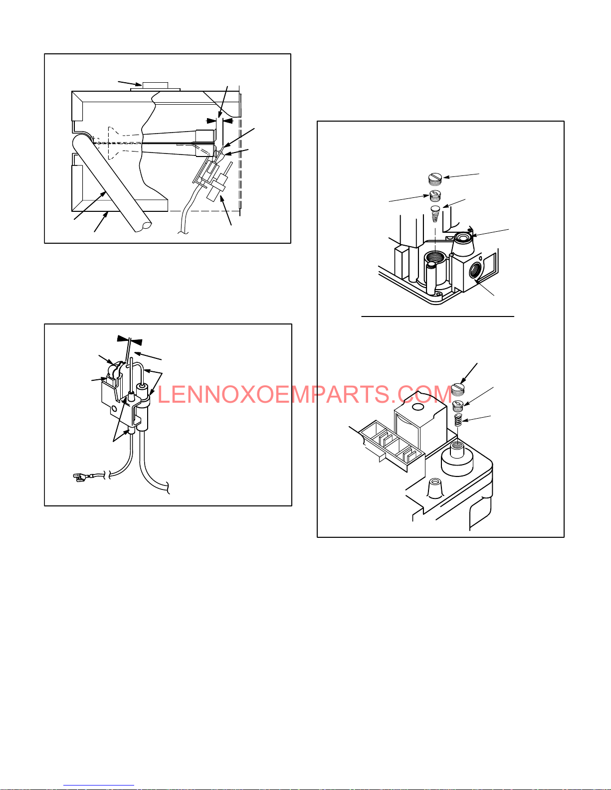
13-Pilot, Spark Electrode, Flame Sensor
(-1 and -2 models)
Figure 18 shows the arrangement of pilot, flame sensor,
spark electrode and burners. The ignition control uses diĆ
rect spark to ignite the pilot. The pilot ignites the burners
and the burners crossĆlight. The flame sensor uses flame
rectification to sense pilot ignition. The ignition control reĆ
quires that pilot flame must be sensed before the main gas
valve is allowed to open. Typically, a 2 to 4 second delay
occurs between the pilot ignition and the main valve openĆ
ing. Figure 19 shows the gap between the tip of the elecĆ
trodes and the burner surface. It is important that the gap
be maintained for consistent ignition of pilot flame.
Page 15
Page 16
LENNOXOEMPARTS.COM
TYPICAL BURNER PILOT/ELECTRODE ORIENTATION
FRESH AIR INTAKE
MANIFOLD
BURNER BOX
view looking at side of burners
GAP
BURNERS
FLAME SENSOR
SPA RK
ELECĆ
TRODE
PILOT
HOOD
FIGURE
18
Both pilot and main burner flame should be predominantly
blue and strong in appearance. Pilot flame must surround
the end of flame sensor for proper operation of pilot safety
circuit.
PILOT HOOD
PILOT
1/8 (.125) Inch "1/32 (.031)
GAP
SPARK ELECTRODE
place when reading manifold pressure.
An LPG changeover kit is available. The kit includes main and
pilot burner orifices (pilot orifice for -1 and -2 units only) and a
regulator conversion kit. All L.P. orifices can be identified by a
band around the orifice. Natural gas orifices do not have the
band.
HONEYWELL VR8204 GAS VALVE
REGULATOR ADJUSTMENT SCREW LOCATION
PRESSURE
REGULATOR
ADJUSTING
SCREW
(White)
REGULATOR
COVER SCREW
(Black)
SPRING Tapered End
Down (Red)
INLET
PRESSURE
TAP
GAS INLET
WHITE RODGERS 36E GAS VALVE
REGULATOR ADJUSTMENT SCREW
LOCATION
REGULATOR
COVER SCREW
ADJUSTING SCREW
(White)
PILOT, SPARK ELECĆ
TRODE
FLAME SENSOR
SENSOR WIRE
AND FLAME SENSOR
SPARK WIRE
FIGURE 19
14-Gas Valve
The G26 uses a gas valve manufactured by Honeywell or
White Rodgers. See figure 20. The valve is internally reĆ
dundant to assure safety shutĆoff. If the gas valve must be
replaced, the same type valve must be used.
24VAC terminals and gas control knob are located on top of
the valve. All terminals on the gas valve are connected to
wires from the ignition control. 24V applied to the MV" termiĆ
nals on the Honeywell or M/C or 1/2 terminals on the White
Rodgers opens the main valve. Inlet and outlet pressure taps
are located on the valve. A regulator adjustment screw (figure
20 ) is located on the valve. Regulator cover screw must be in
SPRING
FIGURE 20
100% Sealed Combustion
The burner box is completely sealed and operates under a
negative pressure. A pressure hose is connected from the
burner box to the gas valve regulator and differential presĆ
sure switch. The gas valve senses the pressure in the
burner box and changes gas valve output based on
changes in burner box pressure. The intent is to compenĆ
sate for different vent configurations which can greatly afĆ
fect the rate of the unit.
Page 16
Page 17

LENNOXOEMPARTS.COM
NORMAL OPERATION (Natural Gas Units)
3.5
3.4
OPERATION AT THIS EXTREME
MAY INDICATE A BLOCKED
OUTLET OR OTHER PROBLEM
3.3
3.2
3.1
3.0
2.9
2.8
GAS VALVE OUTPUT
2.7
2.6
MANIFOLD PRESSURE (positive inches water column)
2.5
Gray area indicates normal operating range + 10% of manifold pressure
The purpose of this chart is to explain unit operation . Each unit may vary depending
on installation, altitude, intake/exhaust configuration and other factors.
OPERATION AT THIS EXTREME
MAY INDICATE A BLOCKED
INLET OR OTHER PROBLEM
BURNER BOX PRESSURE
(Negative inches water gauge
measured on right side of burner box)
FIGURE 21
15-Differential Pressure Switch (S64)
(Combustion Air Prove Switch)
G26 series units are equipped with a differential pressure
switch located on the vestibule panel. The switch is conĆ
nected to the combustion air blower housing by means of a
flexible silicon hose. A separate hose connects the presĆ
sure switch to the burner box and the gas valve regulator.
The switch monitors air pressure in the combustion air
blower housing and burner box.
The switch is a singleĆpole singleĆthrow normally open
pressure switch electrically connected in series with the
ignition control. The purpose of the switch is to prevent
burner operation if the combustion air blower is not operatĆ
ing or if sufficient combustion air is not available,
On startĆup, the switch senses that the combustion air blowĆ
er is operating. It closes a circuit to the ignition control when
the difference in pressure across the pressure switch inĆ
creases above 0.2 in. w.c. The pressure sensed by the
-1.0-0.20 -0.4 -0.6 -0.8
switch is relative to the pressure in the burner box. In order
for the furnace to operate, the larger negative must alĆ
ways be on the combustion air blower side of the
switch. If the flue or air inlet become obstructed during opĆ
eration, the switch senses a loss of pressure differential
(drops below 0.20 in. negative w.c.) and opens the circuit to
the ignition control.
NORMAL OPERATION (L.P. Gas Units)
7.0
6.9
OPERATION AT THIS EXTREME
MAY INDICATE A BLOCKED
OUTLET OR OTHER PROBLEM
6.8
6.7
6.6
6.5
6.4
6.3
GAS VALVE OUTPUT
6.2
6.1
MANIFOLD PRESSURE (positive inches water column)
6.0
OPERATION AT THIS EXTREME
MAY INDICATE A BLOCKED
INLET OR OTHER PROBLEM
-1.0-0.20 -0.4 -0.6 -0.8
BURNER BOX PRESSURE
(Negative inches water column
measured on right side of burner box)
Gray area indicates normal operating range + 10% of manifold pressure
The purpose of this chart is to explain unit operation . Each unit may vary depending
on installation, altitude, intake/exhaust configuration and other factors.
FIGURE 22
Figures 21 and 22 show how gas valve output changes as
burner box pressure changes. Generally, a lower burner
box pressure produces a leaner gas/air mixture and a
higher burner box pressure produces a richer mixture. A
procedure showing how to check manifold pressure is
shown on page 29.
DIFFERENTIAL PRESSURE SWITCH CIRCUITRY
BURNĆ
TEE
DIFFERENTIAL
PRESSURE
SWITCH
COMBUSTION
AIR PRESĆ
SURE SENSĆ
ING HOSE
COMBUSTION
AIR BLOWER
LEFT SIDE OF PRESSURE SWITCH = MORE NEGATIVE
RIGHT SIDE OF PRESSURE SWITCH = LESS NEGATIVE (Closer to Zero)
ER
BOX
HOSE
BARB
BURNER
BOX
SENSING
HOSE
GAS
VALV E
SENSING
HOSE
GAS
VALV E
PRESSURE
SWITCH
SENSING
HOSE
FIGURE 23
The switch is factory set and is not adjustable. It is a safety
shutĆdown control and MUST not be bypassed.
Figure 24 shows the pressure differential required to obĆ
tain unit operation. If the switch does not successfully
sense the required differential, the switch cannot close
and the furnace cannot operate.
When measuring the pressure differential, readings
should be taken at the pressure switch.
Page 17
Page 18

LENNOXOEMPARTS.COM
-1.2
CHART REPESENTS NORMAL OPERATING
CHARACTERISTICS OF THE PRESSURE SWITCH ONLY
AND SHOULD NOT BE USED FOR TROUBLSHOOTING
-1.0
-0.8
-0.6
-0.4
-0.2
COMBUSTION AIR BLOWER STATIC PRESSURE
DIFFERENTIAL SWITCH CLOSED
0
-0.4 -0.6 -0.8 -1.2
BURNER BOX STATIC PRESSURE
FIGURE 24
Temporarily jumpering the pressure switch when troubleĆ
shooting will determine if the pressure switch and furnace
are operating properly. However, this may not indicate if
the sealed combustion system is operating properly. If the
unit cannot attain 0.2 inches differential, the unit will not
operate. Be sure to remove jumper when finished. See
Warning this page.
WARNING
Safety Hazard. Turn off gas supply before jumpĆ
ering switch or testing switch differential. If
switch is operating properly and sealed comĆ
bustion system is operating improperly, a poĆ
tentially lethal situation will be created when
switch is bypassed. DO NOT ALLOW UNIT TO
OPERATE WITH SAFETY SYSTEMS BYPASSED.
Checks of pressure differential can be made as an aid in trouĆ
bleshooting. It is important to remember that the switch must
see" 0.2 inches differential in order for the furnace to operate.
Lack of differential usually indicates problems in the intake or
exhaust piping but may indicate problems in the heat exĆ
changer, condenser coil, header boxes, combustion blower or
other components. Generally, if both readings are closer to
zero (figure 24) the unit may have a restricted flue outlet or
other problem. If both readings are farther from zero (figure
24) the unit may have a restricted flue inlet or other problem.
DIFFERENTIAL SWITCH OPEN
(Furnace will not operate)
-1.0-0.20
Measuring pressure differential
The differential pressure is the difference in pressure meaĆ
sured on either side of the pressure switch:
1 - Remove thermostat demand and allow to cycle off.
2 - Disconnect hose from left side of pressure switch and
install Tee as shown in figure 25.
TEE AND 1/4"i.d. RUBBER HOSE FIELD
PROVIDED
USED FOR MEASURING PRESĆ
SURE ACROSS BURNER BOX
AND COMBUSTION AIR BLOWER
TO PRESSURE
SWITCH
TO PRESSURE
SENSING HOSE
TO DRAFT GAUGE
FIGURE 25
3 - Install draft gauge to open end of Tee.
4 - Operate unit and observe draft gauge reading. ReadĆ
ings will change as heat exchanger warms.
a. Take one reading immediately after startup.
b. Take a second reading after unit has reached
steady state (approximately 5 minutes).
5 - Remove thermostat demand and allow to cycle off.
6 - Remove draft gauge and Tee. Reinstall combustion air
sensing hose to left side of pressure switch.
7 - Disconnect hose from right side of pressure switch
and install Tee as shown in figure 25.
8 - Install draft gauge to open end of Tee.
Page 18
Page 19

LENNOXOEMPARTS.COM
9 - Operate unit and observe draft gauge reading. ReadĆ
ings will change as heat exchanger warms.
a. Take one reading immediately after startup.
b. Take a second reading after unit has reached steady
state (approximately 5 minutes). Both readings should
fall above the line shown in figure 24.
10- Compare readings to figure 24. Be sure to compare
only like readings (compare startup reading to startup
reading, then compare steady state reading to steady
state reading). Subtract the absolute steady state
readings from one another. This will be the pressure
differential. In order for the furnace to operate, the
larger negative must always be on the combustion
air blower side of the switch
Example - one side of the pressure switch reads .60"
and the other side of the pressure switch reads .10".
Pressure differential is .60" - .10"= .50"
The pressure differential should be greater
than 0.20" W.C.
(49.72Pa).
11- When test is complete, remove thermostat demand
and allow unit to cycle off.
12- Remove draft gauge and Tee. Reinstall pressure
switch sensing hose to left side of pressure switch.
If pressure switch does not close at start up or differential is
less than .20" the following should be checked.
1 - Restriction in exhaust and or intake vent.
2 - Pressure switch lines are routed correctly and for
damage.
3 - Condensate in pressure switch lines.
4 - Wiring of pressure switch to furnace.
5 - Blocked heat exchanger or leak in heat exchanger.
II-PLACEMENT AND INSTALLATION
Make sure unit is installed in accordance with installation
instructions and applicable codes.
A-PVC Joint Cementing Procedure
6 - Promptly apply solvent cement to end of pipe and inĆ
side socket surface of fitting. Cement should be apĆ
plied lightly but uniformly to inside of socket. Take
care to keep excess cement out of socket. Apply secĆ
ond coat to end of pipe.
NOTE-Time is critical at this stage. Do not allow primer
to dry before applying cement.
7 - Immediately after applying last coat of cement to pipe,
and while both inside socket surface and end of pipe
are wet with cement, forcefully insert end of pipe into
socket until it bottoms out. Turn pipe 1/4 turn during
assembly (but not after pipe is fully inserted) to distribĆ
ute cement evenly. Once joint is made, PVC may
swell. Hold joint together until bonded (approximately
20 seconds).
NOTE-Assembly should be completed within 20 secĆ
onds after last application of cement. Hammer blows
should not be used when inserting pipe.
8 - After assembly, wipe excess cement from pipe at end
of fitting socket. A properly made joint will show a
bead around its entire perimeter. Any gaps may indiĆ
cate a defective assembly due to insufficient solvent.
9 - Handle joints carefully and support properly until comĆ
pletely set.
B-Venting Considerations
The thickness of construction through which vent/air intake
pipes may be installed is 24" (610mm) maximum and 3"
(76mm) minimum. If a G26 furnace replaces a furnace which
was commonly vented with another gas appliance, the size
of the existing vent pipe for that gas appliance must be
checked. Without the heat of the original furnace flue prodĆ
ucts, the existing vent pipe may be oversized for the single
water heater or other appliance. The vent should be checked
for proper draw with the remaining appliance.
CAUTION
WARNING
DANGER OF EXPLOSION! Fumes from PVC glue
may ignite during system check. Remove spark
plug wire from ignition control before 120V power
is applied. Reconnect wire after two minutes.
1 - Measure and cut vent pipe to desired length.
2 - Debur and chamfer end of pipe, removing any ridges
or rough edges. If end is not chamfered, edge of pipe
may remove cement from fitting socket and result in a
leaking joint.
3 - Clean and dry surfaces to be joined.
4 - Test fit joint and mark depth of fitting on outside of
pipe.
5 - Uniformly apply liberal coat of PVC primer for PVC or
ABS cleaner for ABS for at least 5 to 15 seconds to inĆ
side socket surface of fitting and male end of pipe to
depth of fitting socket. Remove puddles of primer before
applying cement.
Page 19
Insufficient combustion air can cause headaches,
nausea, dizziness or asphyxiation. Excessive exĆ
posure to contaminated combustion air will result
in safety and performance related problems.
Avoid exposure to the following substances in the
combustion air supply:
Permanent wave solutions;
Chlorinated waxes and cleaners;
Chlorine base swimming pool chemicals;
Water softening chemicals;
De-icing salts or chemicals;
Carbon tetrachloride;
Halogen type refrigerants;
Cleaning solvents (such as perchloroethylene);
Printing inks, paint removers, varnishes, etc.;
Hydrochloric acid;
Cements and glues;
Antistatic fabric softeners for clothes dryers; and
Masonry acid washing materials.
Page 20

LENNOXOEMPARTS.COM
Intake Piping
1 - Cement intake piping in slip connector located at top
of unit.
2 - Route piping to outside of structure. Continue with
installation following instructions given in exhaust and
intake piping termination section.
Exhaust Piping
1 - Cement exhaust piping into flue collar socket located
on the left side of the top cap.
2 - All horizontal runs of exhaust pipe must slope back toĆ
ward unit. A minimum of 1/4" (6mm) drop for each 12"
(305mm) of horizontal run is mandatory for drainage.
Horizontal runs of exhaust piping must be supported
every 5 ft. (1.52m) using hangers for schedule 40 pipe.
All other pipe must be supported every 3 ft. (.91m).
NOTE - Exhaust piping should be checked carefully to
make sure there are no sags or low spots.
NOTE - Exhaust piping must be insulated with 1/2"
(13mm) Armaflex or equivalent when run through unĆ
heated space. Do not leave any area of exhaust pipe
open to outside air; exterior exhaust must be insulated
with 1/2" (13mm) Armaflex or equivalent.
CAUTION
Do not discharge exhaust into an existing stack
or stack that also serves another gas appliance.
If vertical discharge through an existing unused
stack is required, insert PVC pipe inside the stack
until the end is beyond the top or outlet end of the
metal stack.
CAUTION
The exhaust vent pipe operates under positive
pressure and must be completely sealed to preĆ
vent leakage of combustion products into the livĆ
ing space.
Removal of Unit from Common Venting System
In the event that an existing furnace is removed from a
venting system commonly run with separate gas apĆ
pliances, the venting system may be too large to properly
vent the remaining attached appliances. The following test
should be conducted while all appliances (both in operaĆ
tion and those not in operation) are connected to the comĆ
mon venting system. If the venting system has been
installed improperly, corrections must be made as outlined
in the previous section.
1 - Seal any unused openings in the common venting sysĆ
tem.
2 - Visually inspect the venting system from proper size
and horizontal pitch and determine there is no blockĆ
age or restriction, leakage, corrosion and other defiĆ
ciencies which could cause an unsafe condition.
3 - Insofar as is practical, close all building doors and winĆ
dows and all doors between the space in which the apĆ
pliances remaining connected to the common venting
system are located and other spaces of the building.
Turn on clothes dryers and any appliances not conĆ
nected to the common venting system. Turn on any exĆ
haust fans, such as range hoods and bathroom exĆ
hausts, so they will operate at maximum speed. Do not
operate a summer exhaust fan. Close fireplace dampĆ
ers.
4 - Follow the lighting instruction. Place the appliance
being inspected in operation. Adjust thermostat so
appliance will operate continuously.
5 - Test for spillage at the draft hood relief opening after 5
minutes of main burner operation. Use the flame of
match or candle, or smoke from a cigarette, cigar.
6 - After it has been determined that each appliance reĆ
maining connected to the common venting system
properly vents when tested as outlined above, return
doors, windows, exhaust fans, fireplace dampers and
any other gasĆburning appliance to their previous
condition of use.
7 - If improper venting is observed during any of the
above tests, the common venting system must be
corrected. The common venting system should be resized to approach the minimum size as determined by
using the appropriate tables in appendix G in the curĆ
rent standards of the National Fuel Gas Code ANSI
Z223-1 in the U.S.A., and the appropriate Category 1
Natural Gas and Propane appliances venting sizing
tables in the current standards of the CAN/
CGA-B149.1 and .2 in the Natural Gas and Propane
Installation Code in Canada.
Intake and Exhaust Piping Terminations
Intake and exhaust pipes may be routed either horizontally
through an outside wall or vertically through the roof. In atĆ
tic or closet installations, vertical termination through the
roof is preferred. Figures 26 through 38 show typical terĆ
minations.
1 - Use recommended piping materials for both intake
and exhaust piping.
2 - Secure all joints, including drain leg, gas tight using
approved primer and cement.
Page 20
Page 21

LENNOXOEMPARTS.COM
3 - Piping diameters should be determined according to
length of pipe run. See vent pipe specifications on
page 6. Locate intake piping upwind (prevailing wind)
from exhaust piping. To avoid re-circulation of exĆ
haust gas on roof terminations, end of exhaust pipe
must be higher than intake pipe.
Exhaust and intake exits must be in same pressure
zone. Do not exit one through the roof and one on the
side. Also, do not exit the intake on one side and the
exhaust on another side of the house or structure.
4 - Intake and exhaust pipes should be placed as close
together as possible at termination end (refer to ilĆ
lustrations). Maximum separation is 3" (76mm) on
roof terminations and 6" (152mm) on side wall terĆ
minations.
5 - Exhaust piping must terminate straight out or up as
shown. In rooftop applications, a 2" X 1-1/2" reducer for
2" venting, 3" x 2" reducer for 3" venting must be used
on the exhaust piping after it exits the structure to imĆ
prove the velocity of exhaust away from the intake pipĆ
ing.
On roof terminations, the intake piping should termiĆ
nate straight down using two 90 elbows (See figure
26).
Inches(mm)
3(76) MAX.
3 x 2 (76 x 51) OR
2 x 1-1/2 (51 x 38)
PVC REDUCER
NOTE - If winter design temperature is below 32 F (0C), exĆ
haust piping must be insulated with 1/2" (13mm), Armaflex or
equivalent when run through unheated space. Do not leave
any surface area of exhaust pipe open to outside air; exterior
exhaust pipe must be insulated with 1/2" (13mm) Armaflex or
equivalent. In extreme cold climate areas, 3/4" (19mm) ArĆ
maflex or equivalent is recommended. Insulation on outside
runs of exhaust pipe must be painted or wrapped to protect
insulation from deterioration.
NOTE - During extremely cold temperatures, below
approximately 20F (6.67C), units with long runs of vent
pipe through unconditioned space, even when insulated,
may form ice in the exhaust termination that prevents the
unit from operating properly. Longer run times of at least 5
minutes will alleviate most icing problems. Also, a heating
cable may be installed on exhaust piping and termination
to prevent freeze-ups. Heating cable installation kit is
available from Lennox. See Condensate Piping section for
part numbers.
NOTE - Care must be taken to avoid re-circulation of exĆ
haust back into intake pipe.
6 - On field supplied terminations for side wall exits, exĆ
haust piping should extend a minimum of 12"
(305mm) beyond the outside wall. Intake piping
should be as short as possible. See figure 27.
1/2 (13) ARMAFLEX
INSULATION IN
UNCONDITIONED SPACE
12 (305) MIN.
2 X 1-1/2
(51 x 38)
PVC REDUCER
8 (203) MIN
12 (305) ABOVE
AVERAGE SNOW
ACCUMULATION
3 (76) OR
2 (51) PVC
PROVIDE SUPPORT
FOR INTAKE AND
EXHAUST LINES
(15F75) LB-49107CC for 2 (51) Venting
(44J41) LB-65678A for 3 (76) Venting
ROOF TERMINATION KIT
1/2 (13) FOAM
INSULATION IN
UNCONDITIONED
SPACE
UNCONDITIONED
ATTIC SPACE
FIGURE 26
IMPORTANT
Do not use screens or perforated metal in intake
and exhaust terminations. Doing so will cause
freeze-ups and may block the terminations.
2 (51) PVC 1-1/2 (38) PVC
1/2 (13) ARMAFLEX
Inches (mm)
(15J74) LB-49107CB for 2 (50.8) Venting
INSULATION
OUTSIDE
WALL
TOP VIEW
WALL RING KIT
6 (152)
MAXIMUM
8 (203)
MINIMUM
2 (51) PVC
COUPLING
FIGURE 27
7 - On field supplied terminations, a minimum separation
distance between the end of the exhaust pipe and the
end of the intake pipe is 8" (203mm).
Page 21
Page 22

LENNOXOEMPARTS.COM
8 - If intake and exhaust piping must be run up a side wall
to position above snow accumulation or other obĆ
structions, piping must be supported every 3 ft. (.91m)
as shown in figure 33. Refer to figures 31 and 32 for
proper piping method. WTK wall termination kit must
be extended for use in this application. See figure 36
or use kit WTKX shown in figure 37. When exhaust
and intake piping must be run up an outside wall, the
exhaust piping is reduced to 1-1/2" (38mm) after the
final elbow. The intake piping may be equipped with a
90 elbow turndown. Using turndown will add 5ft.
(1.5m) to the equivalent length of the pipe.
1/2 (12.7) FOAM INSULATION
IN UNCONDITIONED SPACE
Inches(mm)
EXHAUST
TERMINATION
EXHAUST
INTAKE
TERMINATION
INTAKE
Inches (mm)
CONCENTRIC WALL TERMINATION
(60G77) LB-49107CE for G26-50 & -75 Units Only
(33K97) LB-87942 for G26-100 & -125 Units Only
12 (305) Min.
above grade.
FIGURE 30
OUTSIDE WALL
Optional Turndown
Shown
TOP VIEW
WALL TERMINATION
(22G44) LB-49107CD for 2 (50.8) Venting
(44J40) LB-65701A for 3 (76.2) Venting
(Intake Only)
FIGURE 28
EXHAUST
TERMINATION
INTAKE
TERMINATION
EXHAUST
CONCENTRIC ROOFTOP TERMINATION
(60G77) LB-49107CE for G26-50 & -75 Units Only
(33K97) LB-87942 for G26-100 & -125 Units Only
12 (305) ABOVE
AVERAGE SNOW
ACCUMULATION
INTAKE
Inches (mm)
FIGURE 29
IMPORTANT
For Canadian Installations Only:
In accordance to CAN/CGA-B149.1 and .2, the
minimum allowed distance between the combusĆ
tion air intake inlet and the exhaust outlet of other
appliances shall not be less than 12" (305mm).
Inches(mm)
UNCONDITIONED
SPACE
OUTSIDE WALL
PROVIDE SUPPORT
FOR INTAKE AND
EXHAUST LINES EVERY
36 (914)
1/2 (13) FOAM
INSULATION IN
UNCONDITIONED
SPACE
WALL RING TERMINATION
*This reducer is not necessary for G26-50 units using 1-1/2" venting.
See venting table on page 6 for maximum venting lengths with this
(15F74) LB-49107CB for 2" (51) Venting
SIDE VIEW
arrangement.
12 (305) MIN. for 2 (51)
20 (508) MAX. for 3 (76)
8 (203)
MIN.
12 (305) ABOVE
AVERAGE SNOW
ACCUMULATION
1/2 (13) FOAM
INSULATION
FIGURE 31
9 - Position termination ends so they are free from any obĆ
structions and above the level of snow accumulation
(where applicable). Termination ends must be a miniĆ
mum of 12" (305mm) above grade level. Do not point
into window wells, stairwells, alcoves, courtyard areas
or other recessed areas. Do not position termination
ends closer than 12" below roof eaves or above a walkĆ
way. Since the G26 is a certified direct vent, Category
IV gas furnace, the location of the termination is limited
by building codes. In the absence of local codes, refer
to the current National Fuel Gas Code ANSI Z223-1 in
U.S.A., and current standards CAN/CGA-B149.1 /.2 of
the Natural Gas and Propane Installation Instructions
in Canada for details. The termination should be at
least 12" (305mm) from any opening through which
flue products could enter the building.
Page 22
Page 23

LENNOXOEMPARTS.COM
When horizontally vented, minimum clearance for
termination from electric meters, gas meters, regulaĆ
tors and relief equipment is 4 ft. (1.2m) for US installaĆ
tions. Refer to the current CAN/CGA-B149.1 and .2
for installations in Canada or with authorities having
local jurisdiction.
At vent termination, care must be taken to maintain
protective coatings over building materials (proĆ
longed exposure to exhaust condensate can destroy
protective coatings). It is recommended that the exĆ
haust outlet not be located within 6 feet (1.8m) of a
condensing unit because the condensate can damĆ
age the painted coating.
IMPORTANT
Combustion air intake inlet and exhaust outlet
should not be located within 6 ft. (1.8m) of dryer vent
or combustion air inlet or outlet of another apĆ
pliance. Piping should not exit less than 3 ft. (.91m)
from opening into another building.
10- Suspend piping using hangers at a minimum of every
5 feet (1.52m) for schedule 40 PVC and every 3 feet
(.91m) for ABS-DWV, PVC-DWV, SPR-21 PVC, and
SDR-26 PVC piping. A suitable hanger can be fabriĆ
cated by using metal or plastic strapping or a large
wire tie.
11- In areas where piping penetrates joists or interior
walls, hole must be large enough to allow clearance
on all sides of pipe through center of hole using a
hanger.
12- Isolate piping at the point where it exits the outside
wall or roof.
13- When furnace is installed in a residence where unit is
shut down for an extended period of time, such as a
vacation home, make provisions for draining condenĆ
sate collection trap and lines.
14- Based on the recommendation of the manufacturer, a
multiple furnace installation may use a group of up to
four termination kits WTK assembled together horizonĆ
tally, as shown in figure 35.
Inches(mm)
INSULATION
3 (76) OR
2 (51) 90 ELBOW
Optional TurnĆ
down
(Not Shown)
May Be Used on
Intake Only
(22G44) LB-49107CD for 2(51) Venting
(44J40) LB-65701A for 3(76) Venting
METAL OR PLASTIC
STRAPĆ
PING
OR LARGE
WIRE TIES
1/2 (13)
FOAM
FRONT VIEW
WALL TERMINATION
REDUCER BUSHING LOCAĆ
FOR OFFSET TERMINATION
FIGURE 32
3 x 2 (76 x 51) OR
2 x 1-1/2 (51 x 38)
TION
3 (76) OR
2 (51) 90 ELBOW
Inches (mm)
Front View
INTAKE
VENT
1/2 (13) Foam
Insulation in
Unconditioned Space
Inches (mm)
WALL TERMINATION KIT (30G28) WTK
12
(305)
(127)
Side View
EXHAUST VENT
VENT TERMINATIONS
FIGURE 34
EXHAUST VENT
5
INTAKE VENT
OUTSIDE WALL
FIGURE 33
Page 23
Page 24

LENNOXOEMPARTS.COM
Front View
INTAKE VENT
EXHAUST
VENT
18 MAX.
(457)
5
(127)
5-1/2
(140)
12
(305)
Front View
34
(864)
9
(229)
INTAKE
VENT
EXHAUST
VENT
NOTE-Enclosed exhaust pipe
is insulated with 1/2" (13mm)
foam insulation. If intake and
exhaust pipes are reversed, slit
and remove foam insulation
and reapply to other vent. ExĆ
haust vent must be insulated.
Side View
Inches (mm)
OPTIONAL VENT TERMINATION FOR
Front View
INTAKE
AIR
5
(127)
EXHAUST VENT
INTAKE
MULTIPLE UNIT INSTALLATION
WALL TERMINATION KIT WTK
FIGURE 35
(305)
5Ć1/2
(140)
EXHAUST
AIR
12
COVER EXHAUST
EXHAUST
GRADE
Side View
VENT
VENT WITH
1/2 (13)
FOAM
INSULATION
AIR
12 MIN.
(305)
Above Grade
Side View
4
(102)
12
(305)
GRADE
EXHAUST VENT
8 MIN.
(203)
INTAKE
VENT
OUTSIDE WALL
GRADE
VENT TERMINATIONS
MODEL WTKX (30G79)
EXTENSION RISER FOR GRADE CLEARANCE
FIGURE 37
G26 VENTING IN EXISTING CHIMNEY
3" - 8"
8" - 12"
(203mm - 305mm)
(76mm-
203mm)
INTAKE
AIR
8 (203)
Minimum
Inches (mm)
12 (305)
Minimum
ABOVE GRADE
GRAD
E
VENT TERMINATIONS
MODEL WTK WALL TERMINATION KIT (30G28)
EXTENDED VENT FOR GRADE CLEARANCE
FIGURE 36
Page 24
3" - 8"
(76mm-
203mm)
NOTE-Do not discharge exhaust gases directly into any chimney or vent stack. If vertiĆ
cal discharge through an existing unused chimney or stack is required, insert piping
inside chimney until the pipe open end is above top of chimney and terminate as illusĆ
trated. In any exterior portion of chimney, the exhaust vent must be insulated. An alterĆ
nate method is to fill the chimney with vermiculite or equal to take advantage of its
acoustic and thermal properties.
FIGURE 38
Page 25

LENNOXOEMPARTS.COM
Condensate Piping
This unit is designed for either rightĆ or leftĆside exit of conĆ
densate piping. Condensate drain line should be routed
only within the conditioned space to avoid freezing of conĆ
densate and blockage of drain line. An electric heat cable
should be used where condensate drain is exposed to unĆ
conditioned areas. The following procedure is for all G26
units.
1 - Determine which side condensate will exit the unit.
2 - Connect 1/2" (13mm) plastic pipe plug (provided) in
the unused end of the condensate trap. Install plug so
that it is sealed water tight yet able to be removed. Do
not permanently seal the connection. Teflon tape is
recommended to seal joint. See figure 40.
FLUE TRAP
UNIT CABINET
Y" CONNECTOR
HOSE BARB
ASSEMBLY
G26-1 and -2
Models
3 - Use the provided adapter (1/2" PVC x 1/2" MPT) and
the nipple (1/2" PVC) to carry drainage outside the
cabinet. If a field substitute is needed, 1/2" CPVC x
1/2" MPT adapter and 1/2" CPVC is acceptable for
use.
4 - Glue nipple to the adapter using the procedures outĆ
lined in the Joint Cementing Procedures" section.
The nipple/adapter assembly should be connected
in a nonĆpermanent manner and must be water tight.
Teflon tape is recommended to seal the joint.
For RightĆHand Side Condensate Exit:
Install the nipple/adapter assembly from the outside
of the cabinet and insert the adapter into the
threaded opening in the condensate trap.
For LeftĆHand Side Condensate Exit:
Insert nipple/adapter assembly from the left hand
side of the cabinet and through the combustion air
blower mounting structure into the threaded openĆ
ing in the condensate trap.
5 - Connect field supplied plumbing to nipple and route to
open drain. Plumbing should be vented to a point higher
than the condensing coil. See figure 41.
DETAIL OF FLUE TRAP
BOOT OR CAP
RUBBER CONNECTOR
HOSE CLAMPS
FIGURE 39
CONDENSATE ASSEMBLY
(For left or right installation)
COMBUSTION AIR
BLOWER BRACKĆ
ET
NIPPLE
ADAPTER
PLUG
FIGURE 40
CAUTION
Do not use copper tubing or existing copper
condensate lines for drain line.
CONDENSATE PLUMBING
(Plumbing must be vented higher than coil.)
COLD HEADĆ
ER
BOX
NIPPLE
ADAPTER
CONDENSATE TRAP
BOOT OR CAP
FIGURE 41
Page 25
Page 26

LENNOXOEMPARTS.COM
DETAIL OF
FLUE TRAP
4
3
4
FLUE TRAP
HOSE BARB
5
G26 -3 THROUGH -6 MODEL CONDENSATE
REMOVAL PROCESS
COLD
HEADER
BOX
1
VENT
7
FLUE
DRAIN
HOSE
COMBUSTION
AIR BLOWER
2
HEADER BOX
CONDENSATE TRAP
6
Condensate Removal Process:
1- Condensate mixed with flue products
exits the coil and enters the cold headĆ
er box.
2- Condensate and flue products are sepaĆ
rated. Flue products are drawn into the
combustion air blower while condensate
is drained into the header box condenĆ
sate trap.
3- Flue products are expelled into the flue.
As flue products travel up and out, they
cool and more condensate is produced.
4- Condensate travels down the walls of
the flue pipe and into drain hose.
5- Water drains down through the flue
drain hose and is emptied into the
header box condensate trap.
6- When the cold header box condensate
trap is full, water begins draining out the
condensate drain pipe.
7- An external condensate trap is not reĆ
quired, but a vent is required. The vent
must extend above the height of the conĆ
denser coil (approx. 1 inch above the top
of the cold header box).
DETAIL OF COLD HEADER CONDENSATE TRAP
CONDENSATE
FROM COIL
1
COLD HEADER BOX
5
SIDE DETAIL OF
HEADER BOX
CONDENSATION
TRAP
6 - Connect condensate drain line (1/2" [13mm] SDR 11
plastic pipe or tubing) to condensate connection on
drip leg assembly and route to open drain. CondenĆ
sate line must be sloped downward away from drip
leg to drain. If drain level is above drip leg, condenĆ
sate pump must be used to condensate line. CondenĆ
sate drain line should be routed within the conditioned
space to avoid freezing of condensate and blockage
of drain line. If this is not possible, a heat cable kit may
HOSE BARB
COIL OPENING BEHIND
COLD HEADER BOX
1/2"MPT PLUG
RUBBER BOOT OR CAP
FLUE DRAIN HOSE
FIGURE 42
1
2
1/2"PVC
1/2"MPT TO FEMALE
PVC PIPE ADAPTER
FRONT DETAIL OF
HEADER BOX
CONDENSATION
TRAP
be used on the condensate drip leg and line. Heating
cable kit is available from Lennox in various lengths;
6ft. (1.8m) - kit no. 18K48; 24ft. (7.3m) - kit no. 18K49;
and 50ft. (15.2m) - kit no. 18K50.
III-STARTĆUP
A-Preliminary and Seasonal Checks
1 - Inspect electrical wiring, both field and factory installed
for loose connections. Tighten as required.
6
Page 26
Page 27

LENNOXOEMPARTS.COM
2 - Check voltage at disconnect switch. Voltage must be
within range listed on the nameplate. If not, consult the
power company and have voltage condition corrected
before starting unit.
3 - Inspect condition of condensate traps and drain asĆ
sembly. Disassemble and clean seasonally.
B-Heating StartĆUp
FOR YOUR SAFETY READ BEFORE LIGHTING
CAUTION
Shock and burn hazard.
G26 units are equipped with the SureLight ignition
system. Do not attempt to light manually.
WARNING
Do not use this furnace if any part has been underĆ
water. Inspect the furnace and replace any part of
the control system and any gas control which has
been under water.
How To Operate Gas Valve (Figure 43)
WARNING
If you do not follow these instructions exactly, a
fire or explosion may result causing property
damage, personal injury or loss of life.
1 - STOP! Read the safety information at the beginning of
this section.
2 - Set thermostat to lowest setting.
3 - Turn off all electrical power to furnace.
4 - This appliance is equipped with an ignition device
which automatically lights the burner. Do not try to
light the burner by hand.
5 - Remove unit access panel.
6 - On Honeywell VR8204 gas valves, turn knob on gas
valve clockwise
gas valves, move switch to OFF. Do not force. See figĆ
ure 43.
HONEYWELL VR8204 SERIES GAS VALVE
to OFF. For White Rodgers 36E
WARNING
If overheating occurs or if gas supply fails to shut
off, shut off the manual gas valve to the appliance
before shutting off electrical supply.
CAUTION
Before attempting to perform any service or mainĆ
tenance, turn the electrical power to unit OFF at
disconnect switch.
BEFORE LIGHTING smell all around the appliance area
for gas. Be sure to smell next to the floor because some
gas is heavier than air and will settle on the floor.
Use only your hand to push in or turn the gas control knob.
Never use tools. If the knob will not push in or turn by hand,
do not try to repair it, call a qualified service technician.
Force or attempted repair may result in a fire or explosion.
G26 units are equipped with the SureLight ignition system.
DO NOT attempt to manually light burners on this furnace.
Each time thermostat calls for heat, burners will be automatiĆ
cally lit. The ignitor does not get hot when there is no call for
heat on units with SureLight ignition system.
ON
OFF
GAS VALVE SHOWN IN OFF POSITION
WHITE RODGERS
36E GAS VALVE
GAS VALVE
SHOWN
IN OFF
POSITION
7 - Wait five (5) minutes to clear out any gas. If you then
smell gas, STOP! Immediately call your gas supplier
from a neighbor's phone. Follow the gas supplier's inĆ
structions. If you do not smell gas go to next step.
8 - For Honeywell VR8204 gas valves, turn knob on
valve counterclockwise to ON. For White
Rodgers 36E gas valves, move switch to ON.
9 - Replace unit access panel.
10- Turn on all electrical power to unit.
11- Set thermostat to desired setting.
NOTE-When unit is initially started, steps 1 through 11
may need to be repeated to purge air from pilot line.
NOTE-On initial start-ups and when condensate trap
is dry, unit may turn itself off and on to allow condensate
trap to fill. This is normal operation.
FIGURE 43
Page 27
Page 28

LENNOXOEMPARTS.COM
12- If the furnace will not operate, follow the instructions
To Turn Off Gas To Unit" and call your service techniĆ
cian or gas supplier.
To Turn Off Gas To Unit
1 - Set thermostat to lowest setting.
2 - Turn off all electrical power to unit if service is to be
performed.
3 - Remove heat section access panel.
4 - On Honeywell VR8204 gas valves, turn knob on gas
valve clockwise to OFF. For White Rodgers 36E
gas valves, move switch to OFF. Do not force.
5 - Replace unit access panel.
C-Safety or Emergency Shutdown
Turn off unit power. Close manual and main gas valves.
D-Extended Period Shutdown
Turn off thermostat or set to UNOCCUPIED" mode. Close
all gas valves (both internal and external to unit) to guaranĆ
tee no gas leak into combustion chamber. Turn off power
to unit. All access panels, covers and vent caps must be in
place and secured.
Refer to Maintenance" section of this manual for instrucĆ
tions on how to prepare condensate assembly for exĆ
tended period shutdown.
IV-HEATING SYSTEM SERVICE CHECKS
A-A.G.A./C.G.A. Certification
All units are A.G.A. and C.G.A. design certified without
modifications. Refer to the G26 Operation and Installation
Instruction Manual Information.
B-Exhaust CO2 and CO content
Carbon Dioxide is a colorless and odorless gas produced
in small amounts by all furnaces, including the G26, during
combustion process. When the unit is properly installed
and operating normally, the CO2 content of the exhaust is
between 6.0% and 8.0% for natural gas and between
7.5% and 9.5% for L.P. gases. CO content will be less than
0.04% regardless of the gas used. If unit appears to be opĆ
erating normally at or beyond the upper limit of the CO
range, the unit should be checked for abnormally high CO.
Testing for abnormally high CO
One method for testing the CO
ach CO2 test with the Fyrite CO2 indicator. Other methods
of testing CO2/CO are available. Closely follow the instrucĆ
tions included in the test kit you choose. Follow the proceĆ
dure below in order to check CO2/CO on the G26 furnace.
1 - Drill size "R" or 11/32 in. on the exhaust vent, just exitĆ
ing the cabinet and tap 1/8-27 NPT. This hole will be
used to draw your CO2/CO sample.
2 - Install a hose barb connector into test hole.
3 - Attach end of Fyrite sampling tube to hose barb.
4 - Set thermostat to highest setting and allow unit to run
15 minutes.
5 - When CO2/CO testing is complete, turn off unit, reĆ
move hose barb from exhaust vent and use a1/8"
plastic plug to close off port.
2
/CO content is the BacharĆ
2
and CO.
C-Gas Piping
Gas supply piping should not allow more than 0.5"W.C.
drop in pressure between gas meter and unit. Supply gas
pipe must not be smaller than unit gas connection. See gas
pipe capacity table on page 6 of this manual.
Compounds used on gas piping threaded joints should be
resistant to action of liquefied petroleum gas.
D-Testing Gas Piping
When pressure testing gas lines, the gas valve must be
disconnected and isolated. Gas valves can be damaged if
subjected to more than 0.5psig (14" W.C.). See figure 44. If
the pressure is equal to or less than 0.5psig (14"W.C.), use
the manual shut-off valve before pressure testing to isoĆ
late furnace from gas supply.
GAS PIPING TEST PROCEDURE (TYPICAL)
MANUAL MAIN SHUT-OFF
VALVE WILL NOT HOLD
NORMAL TEST PRESSURE
2
FURNACE
ISOLATE
GAS VALVE
Page 28
CAP
GAS VALVE WILL NOT HOLD TEST PRESSURE IN
EXCESS OF 0.5 PSIG (14"W.C.)
FIGURE 44
Page 29

LENNOXOEMPARTS.COM
LEFT SIDE PIPING
MANUAL MAIN
SHUT-OFF
VALV E
GAS VALVE
RIGHT SIDE PIPING
FIGURE 45
GAS VALVE
(STANDARD)
Do not use matches, candles, flame or any other source of
ignition to check for gas leaks.
E-Testing Gas Supply Pressure
When testing supply gas pressure, connect test gauge to
inlet pressure tap (field provided). See figure 44. Check
gas line pressure with unit firing at maximum rate. Low
pressure may result in erratic operation or underfire. High
pressure can result in permanent damage to gas valve or
overfire. For natural gas units, operating pressure at unit
gas connection must be between 4.5" W.C. and 13.0" W.C.
For L.P. gas units, operating pressure at unit gas connecĆ
tion must be between 8.0" and 13.0" W.C.
On multiple unit installations, each unit should be checked
separately, with and without units operating. Supply presĆ
sure must fall within range listed in previous paragraph.
F-Check Manifold Pressure
Manifold Operating Pressure is the manifold pressure
measured during normal operation (sensing burner box
pressure). Manifold Absolute Pressure is the manifold
pressure measured when the gas valve regulator is operĆ
ating at factory preset level (sensing atmospheric presĆ
sure).
After line pressure has been checked and adjusted, check
manifold absolute pressure. Move pressure gauge to outĆ
let pressure tap located on unit gas valve (GV1). Checks of
manifold absolute pressure are made as verification of propĆ
er regulator adjustment.
Manifold operating pressure for the G26 can be measured at
any time the gas valve is open and is supplying gas to the
unit. Normal manifold operating pressure for natural gas
units is 2.5 to 3.5 in. w.c (see figure 21). For LP/propane gas
the correct manifold operating pressure is 7.5 in. w.c. (see
figure 22).
IMPORTANT
For safety, connect a shutĆoff valve between the
manometer and the gas tap to permit shut off of
gas pressure to the manometer.
IMPORTANT
In case emergency shutdown is required, turn off
the main shutĆoff valve and disconnect the main
power to unit. These controls should be properly
labeled by the installer.
When checking piping connections for gas leaks, use preĆ
ferred means. Kitchen detergents can cause harmful corroĆ
sion on various metals used in gas piping. Use of a specialty
Gas Leak Detector is strongly recommended. It is available
through Lennox under part number 31B2001. See Corp.
8411-L10, for further details.
Page 29
The gas valve is factory set and should not require adjustĆ
ment. See table 9. Also, gas valve regulation varies with
burner box pressure (figures 21 and 22).
*Manifold Absolute Pressure Measurement and AdjustĆ
ment
1 - Connect test gauge to outlet tap on gas valve.
2 - Disconnect pressure sensing hose from gas valve
and plug hose. Leave hose barb on valve open to atĆ
mosphere. See figure 46.
3 - Start unit and allow 5 minutes for unit to reach steady
state.
Page 30

LENNOXOEMPARTS.COM
MANIFOLD CHECK
G26 Unit
GAS
VALV E
SENSING
HOSE
GAS
VALV E
TOP VIEW GAS VALVE DETAIL
HOSE
BARG
OUTLET
PRESSURE
TAP
GAS
PIPING
FIGURE 46
4 - While waiting for the unit to stabilize, notice the flame.
Flame should be stable and should not lift from burner.
Natural gas should burn blue. L.P. gas should burn
mostly blue with some orange streaks.
5 - After allowing unit to stabilize for 5 minutes, record
manifold pressure and compare to values given in
table 9. Regulator cap must be installed when reading
pressures.
TABLE 9
GAS VALVE REGULATION*
Unit (Fuel)
Natural
L.P.
Absolute Pressure (outlet) in. W.C.
3.5 +0.3
7.5 +0.7
NOTE-Shut unit off and remove manometer as soon as
an accurate reading has been obtained. Take care to
replace pressure tap plug.
NOTE-During this test procedure, the unit will be
overfiring:
Operate unit only long enough to obtain accurate readĆ
ing to prevent overheating heat exchanger.
Attempts to clock gas valve during this procedure
will be inaccurate. Measure gas flow rate only during
normal unit operation.
6 - When test is complete remove obstruction from hose
and return hose to gas valve barb.
WARNING
Fire and explosion hazard.
These instructions MUST be followed exactly.
Can cause a fire or explosion resulting in property
damage, personal injury or loss of life.
G- Proper Gas Flow (Approximate)
Furnace should operate at least 5 minutes before checkĆ
ing gas flow. Determine time in seconds for two revoluĆ
tions of gas through the meter. (Two revolutions assures
a more accurate time.) Divide by two and compare to time
in table 10 below. Adjust manifold pressure on gas valve
to match time needed.
NOTE- To obtain accurate reading, shut off all other
gas appliances connected to meter.
TABLE 10
GAS METER CLOCKING CHART
Seconds for One Revolution
Natural LP
1 cu ft
Dial
2 cu ft
Dial
1 cu ft
Dial
2 cu ft
DIAL
-50 72 144 180 360
-75 48 96 120 240
-100 36 72 90 180
-125 29 58 72 144
Natural-1000 btu/cu ft LP-2500 btu/cu ft
H-High Altitude Derate
Units are selfĆcompensating for altitude and do not require
kits or adjustment when installed below 7500 ft. elevation.
Manifold pressure should remain the same for both natural
and propane. If unit is installed at an altitude higher than
7500 feet (2248 m), refer to local codes.
NOTE-This is the only permissible field derate for this
appliance.
IMPORTANT
For safety, shut unit off and remove manometer as
soon as an accurate reading has been obtained.
Take care to replace pressure tap plug.
I-Flame Signal
A 20 microamp DC meter is needed to check the flame sigĆ
nal on the SureLight and Johnson G776 ignition control. Use
a flame signal transducer (part number 78H5401) available
from Lennox to measure the flame signal.
Flame (microamp) signal is an electrical current which
passes from the ignition control through the sensor elecĆ
trode during unit operation. Current passes from the senĆ
sor through the flame to ground to complete a safety cirĆ
cuit.
To Measure Flame Signal:
1 - Set the volt meter to the DC voltage scale. Insert transĆ
ducer into the VDC and common inputs. Observe corĆ
rect polarities. Failure to do so results in negative (-)
values.
2 - Turn off supply voltage to control.
3 - Disconnect flame sensor lead from terminal of ignition
control.
Page 30
Page 31

LENNOXOEMPARTS.COM
4 - Connect (+) lead of transducer to ignition control senĆ
G26 1 and 2
and -6 models
sor connection. See figure 47.
5 - Connect (-) lead of the transducer to sensor wire. See
figure 47.
6 - Turn supply voltage on and close thermostat contacts
to cycle system.
7 - When unit lights, read voltage on meter display. ReĆ
member 1 DC volt = 1 DC microamp.
TABLE 11
FLAME SIGNAL MICROAMPS
G26 -1 and -2
models
Normal 0.25
Minimum 0.15
Normal u0.7
G26 -3, -4, -5
-
Low v0.7
Minimum 0.15
FLAME SIGNAL TEST
DIGITAL
METER
SENSOR
WIRE
TRANSDUCER
(+)
(-)
FLAME SENSOR
SENSE" TERMINAL
IGNITION
CONTROL
(G776 SHOWN)
FIGURE47
V-TYPICAL OPERATING CHARACTERISTICS
A-Blower Operation and Adjustment
NOTE- The following is a generalized procedure and
does not apply to all thermostat controls.
1 - Blower operation is dependent on thermostat control
system.
2 - Generally, blower operation is set at thermostat subĆ
base fan switch. With fan switch in ON position, blower
operates continuously. With fan switch in AUTO posiĆ
tion, blower cycles with demand or runs continuously
while heating or cooling circuit cycles.
3 - In all cases, blower and entire unit will be off when the
system switch is in OFF position.
B-Temperature Rise
Temperature rise for G26 units depends on unit input,
blower speed, blower horsepower and static pressure as
marked on the unit rating plate. The blower speed must be
set for unit operation within the range of AIR TEMP. RISE
°F" listed on the unit rating plate.
To Measure Temperature Rise:
1 - Place plenum thermometers in the supply and return
air plenums. Locate supply air thermometer in the first
horizontal run of the plenum where it will not pick up raĆ
diant heat from the heat exchanger.
2 - Set thermostat to highest setting.
3 - After plenum thermometers have reached their highĆ
est and steadiest readings, subtract the two readings.
The difference should be in the range listed on the unit
rating plate. If the temperature is too low, decrease
blower speed. If temperature is too high, first check
the firing rate. Provided the firing rate is acceptable, inĆ
crease blower speed to reduce temperature. To
change blower speed taps see the Blower Speed Taps
section in this manual.
C-External Static Pressure
1 - Measure tap locations as shown in figure 48.
2 - Punch a 1/4" diameter hole
in supply upstream of evapĆ
orator and return air pleĆ
STATIC PRESSURE
TEST
MANOMETER
nums. Insert manometer
hose flush with inside edge
of hole or insulation. Seal
around the hose with perĆ
magum. Connect the zero
G26 UNIT
FIGURE 48
end of the manometer to the discharge (supply) side
of the system. On ducted systems, connect the other
end of manometer to the return duct as above. For
systems with non-ducted returns, leave the other end
of the manometer open to the atmosphere.
3 - With only the blower motor running and the evaporator
coil dry, observe the manometer reading. Adjust blowĆ
er motor speed to deliver the air desired according to
the job requirements.
4 - Pressure drop must not exceed 0.5" W.C.
5 - Seal around the hole when the check is complete.
D-Blower Speed Taps Leadless Motors
-1, -2, -3 and -4 Models
Blower speed tap selection on unleaded motors is accomĆ
plished by changing the taps at the blower motor harness
connector. Disconnect harness connector from motor to exĆ
pose speed selectors. Blower speed selections are listed on
table 12.
To Change Blower Speed Uleaded Motors
1 - Turn off electric power to furnace.
2 - Remove blower access door.
3 - Disconnect blower motor harness from motor.
4 - Pull harness connector and wires through blower acĆ
cess panel opening.
5 - Select desired speeds for heating and cooling. (Red =
heating, Black = cooling, White = common).
6 - Depress harness connector tab to release wire termiĆ
nal. Select connector location for new speed (refer to
unit wiring diagram). Insert wire terminal until it is seĆ
curely in place. See figure 50.
7 - Replace harness connector to motor .
Page 31
Page 32

LENNOXOEMPARTS.COM
To Remove Blower:
1- Turn off line voltage power. Unplug
J69 from P69 located on blower
deck.
2- Disconnect thermostat wiring conĆ
nections by removing low voltage
terminal strip.
3- Disconnect J58/P58 located on blowĆ
er deck.
4- Disconnect J43/P43 from blower
motor.
5- Loosen screws (2) and remove conĆ
trol box from unit. Holes are slotted so
screws do not need to be removed.
6- Remove screws (2) and remove
blower from unit.
3
1
5
26
5
FIGURE 49
4
BLOWER SPEED TAP SELECTION
HARNESS
CONNECTOR
DEPRESS TAB TO RELEASE
WIRE TERMINAL. SELECT
CONNECTOR LOCATION FOR
NEW SPEED (REFER TO UNIT
WIRING DIAGRAM). INSERT
WIRE UNTIL IT IS SECURELY
IN PLACE.
FIGURE 50
TABLE 12
MOTOR
E-Blower Speed Taps Leaded Motors
-5 and -6 Models
Blower speed tap changes are made on the SureLight
control board. See figure 10. Unused taps must be seĆ
cured on dummy terminals "PARK M1" and or "PARK M2"
on the SureLight board. The heating tap is connected to
the "ACB HEAT " terminal and the cooling tap is connected
to the "ACB COOL" terminal. The continuous blower tap is
connected to the "ACB LOW" terminal.
To change existing heat tap, turn off power then switch out
speed tap on "ACB HEAT" with tap connected to "PARK
M1" or "PARK M2". See table 13 for blower motor tap colĆ
ors for each speed.
VI-MAINTENANCE
Retainers for factory supplied return air filter are shown in
figure 51.
BOTTOM RETURN FILTER
REAR FILTER CLIP
SIDE FILTER CLIPS (2)
RETURN AIR
OPENING
FURNACE
BACK
TABLE 13
Page 32
FURNACE
FRONT
FURNACE
BASE BOTTOM
FIGURE 51
A-Filters
At the beginning of each heating season, the system
should be checked as follows:
1 - Filters should be inspected monthly and must be
cleaned or replaced when dirty to ensure proper furĆ
nace operation.
Page 33

LENNOXOEMPARTS.COM
2 - Reusable foam filters used with the G26 can be
washedwith waterand milddetergent. Whendry,they
should be sprayed withfilterhandicoater prior to reinstallation. Filter handicoater is RP Products coating
no. 418andis available as Lennoxpart no. P-8-5069.
3 - If replacement is necessary, order Lennox part no.
31J81 for 14” x 25” (356 x 635mm) filter for G26-50
and -75 units and P-8-7831 for 20” x 25” (508 x
635mm) filter for G26Q4/5-75,G26-100 and -125
units.
B-Cleaning Heat Exchanger and Burners
Ifcleaning theheatexchanger becomesnecessary,follow
the below procedures and refer to figure 1 when disassemblingunit. Usepapers orprotective coveringin frontof
furnace while removing heat exchanger assembly.
1 - Turnoff electrical and gaspowersupplies to furnace.
2 - Remove upper and lower furnace access panels.
3 - Remove four (4) screws around air intake fitting and
lift intake pipe up and away.
4 - Loosen hose clamp securing top of flue transition to
bottomof fluecollar. Removescrew securingfluecollar to top cap and lift exhaust pipe and flue collar up
and away.
5 - If electrical field make-up box is located inside the
unit, it must be removed.
6 - Remove gas supply line connected to gas valve.
7 - Mark all gas valve wires and disconnect them from
valve. Mark and remove wires from flame roll-out
switch.
8 - Remove top cap of unit.
9 - For -1 and -2 units, mark and disconnect spark and
sensorwirefrom ignitioncontrol. For -3units, remove
sensor wire from SureLightcontrol.Disconnect2-pin
plug from the ignitor.
10- Mark and disconnect pressure switch tubing from
both sides of the pressure switch.
11- Loosen two (2) screws holding gas manifold support
at vestibule panel.
12- Remove four (4) burner box screws at the vestibule
panelandremove burnerbox andgasvalve/manifold
assembly with bracket.
13- Drain condensate trap. Disconnect condensate line
from the outside of unit. Remove condensate line
from condensate trap by turning the adapter fitting
counterclockwise. Thefittinghas standard righthand
threads.
14- Disconnect the drain hose from the flue transition to
the elbow on the cold header (collector) box trap. On
-1and -2units removetwo(2)screwfrom flue”Y” trap
at cabinet from door flange.
15- Disconnect the 2-pin plug from the combustion air
blower at the blower deck. Remove four (4) screws
fromcombustionairblowerandremovefluetransition
and blower assembly from cabinet. Take care not to
lose the combustion air orifice.
16- Disconnect 9-pin plug from the blower compartment
at the blower deck.
17- Remove 9-pin plug above the blower deck.
18- Remove the limitswitch andthe pressure switchfrom
the vestibule panel.
19- Remove two (2) screws from the front cabinet flange
attheblowerdeck.Remove frontscrewsfrom cabinet
at blower deck on left and right sides. Cabinet sides
must be slightly spread to clear heat exchanger pas-
sage.
20- Remove screws along vestibule sides and bottom
which secure vestibule panel and heatexchanger as-
sembly to cabinet. Remove heat exchanger then re-
movecold endheaderbox. Removebafflesfrom con-
denser tubes.
21- Back wash heatexchangerwith soapy watersolution
or steam. If steam is used it must be below 275_F
(135_C) .
22- Thoroughly rinse anddrain theheat exchanger.Soap
solution can be corrosive so take care that entire as-
sembly is completely rinsed.
23- Re-install heat exchanger into cabinet making sure
that the clamshells of the heat exchanger assembly
areresting inthe notchesof thesupport locatedat the
rear of the cabinet. This can be viewed by removing
the indoor blower and examining through the blower
opening.
24- Re-secure the supporting screwsalongthe vestibule
sides and bottom to the cabinet.
25- Re-install cabinetscrewson sides and front flangeat
blower deck.
26- Re-install the limit switch and pressure switch on the
vestibule panel.
27- Re-install 9-pin plug to blower deck and connect it to
the 9-pin plug from below the blower deck.
28- Re-install the combustion air blower. Be careful that
theplastic orificeontheblowerinlet hasnot fallenout.
Seefigure 1.Reconnectthe2-pinplug tothe wirehar-
ness. Re-install the flue transition in the cabinet and
re-attach the drain tube. Route the drain tube below
the combustion air blower housing and to the elbow
on thecold header (collector)box trap. Seefigure 23.
29- Re-install condensate line with adapter to conden-
sate trap. Use freshTeflon tape to ensurealeak-free
joint. Re-connect to condensate line outside of the
unit.
Page 33
Page 34

LENNOXOEMPARTS.COM
BURNER ACCESS/REMOVAL
BURNER MOUNTING
BRACKET
2
PATCH PLATE
Simplified Burner Removal:
1- Remove cover by loosening
bottom screws (2) and reĆ
moving cover front screws
(5).
2- Remove pilot tube, spark
wire and sensor wire. ReĆ
move gas valve and manifold
assembly.
3- Remove burner assembly.
1
3
30- ReĆinstall the burner box. Tighten the screws holding
the support bracket. It is important that the glass fiber
gasket not be damaged so it will provide a continuous
seal between the burner box and the vestibule panel.
31- With the pressure switch oriented on the right, reconĆ
nect pressure switch tubing by connecting the tubing
from the burner box to the barb on the bottom and the
tubing from the combustion air blower to the barb on
the top. See figure 23.
32- Reconnect the sensor and ignitor wires.
33- ReĆinstall top cap to unit.
34- ReĆinstall electrical connections to gas valve. Orange
wire to M1 and yellow wire to C2. Reconnect wires to
flame rollĆout switch.
NOTE - Unit is polarityĆsensitive. 120V supply wiring
must be installed correctly.
35- Reconnect main gas line to gas valve.
36- ReĆinstall field makeĆup box if removed.
37- ReĆinstall exhaust pipe/flue collar and secure flue colĆ
lar to the unit top cap using existing screw. Insert the
bottom of the flue collar into the top of the flue transiĆ
tion and tighten hose clamp.
38- ReĆinstall intake pipe fitting to burner box with screws.
39- Replace both upper and lower access panels.
40- Refer to instruction on verifying gas and electrical conĆ
nections when reĆestablishing supply.
41- Following lighting instructions from installation manuĆ
al, light and run unit for 5 minutes to ensure heat exĆ
changer is clean, dry and operating safely.
BARBED PRESSURE
SWITCH ORIFICE
FIGURE 52
PATCH PLATE
Cleaning the Burner Assembly
1 - Turn off electrical and gas power supplies to furnace.
Remove upper and lower furnace access panels.
2 - Disconnect the gas supply line to gas valve. DependĆ
ing on gas plumbing installation, the gas manifold
may move aside enough that breaking the union may
not be necessary.
3 - Remove five (5) screws from edges of burner box
cover. G26-50 units have only four (4) screws.
4 - Loosen two (2) screws on bottom of burner box front.
The cover is key holed at these screw point so screws
do not need to be removed. Pull off cover and set
aside.
6 - On -1 and -2 units disconnect pilot line at the gas
valve. On all units mark all gas valve wires and disĆ
connect them from valve.
7 - ON -1 and -2 units mark and disconnect spark and
sensor wire from the burner box at the ignition control.
On -3 mark and disconnect sensor wires from the
burner box at the SureLight control. Disconnect 2Ćpin
plug from the ignitor at the burner box.
8 - Loosen two (2) screws at the gas manifold support
bracket.
9 - Pull on the left side of the gas manifold and follow with
tension to the right side. The manifold support bracket
will be free of the mounting screws on the vestibule
panel. Set the gas manifold/gas valve assembly
aside. Take care not to damage foam gaskets on each
end of the gas manifold.
10- Using a 1/4" nut driver, remove the burner mounting
screws from underneath the burners.
UNIT VEST PANEL
Page 34
Page 35

LENNOXOEMPARTS.COM
11- While supporting pilot, ignitor and sensor wires (-1,-2
units) or ignitor and sensor lines (-3 units) at the gromĆ
met, grasp burners and simultaneously pull burners
and grommet out of the burner box.
12- Remove ignitor and sensor or pilot bracket assemĆ
blies from burners using a 1/4" nut driver to remove
two screws from each bracket.
13- Clean burner by running a vacuum with a soft brush atĆ
tachment over face of burners. Visually inspect inside of
burners and crossovers for any blockage caused by forĆ
eign matter. Remove any blockage.
14- ReĆinstall ignitor and sensor bracket assemblies on
burners.
NOTE - Ignitor or pilot must be installed on the opposite
side of the burner from the metal button protrusions.
Screws which attached the ignitor bracket must be
installed from the same side as the ignitor and through
the bracket to engage in the smaller holes located in the
burner. The correc t burn er ori entation is with met al butĆ
ton protrusions always pointing up.
15- Replace burner ignitor assembly back into burner box
so that grommet groove fits back into sheet metal
notch and makes a good seal. The burners sit on top
of the burner box flanges. Make certain that the
screws from underneath the box pass through the
larger holes in the flange and engage in the smaller
holes in the burner. ReĆinstall the two screws.
16- ReĆinstall the gas manifold/gas valve assembly by first
inserting the right hand side of the gas manifold into the
burner box. Swing left side of manifold into box while
engaging support bracket to vestibule panel screws.
Check that foam gaskets are providing a seal around
each end of the gas manifold. All gas orifices should be
engaged. If at this point the burners were mounted in
the wrong holes, this needs to be corrected. The saddle
brackets on the gas manifold should be flush with the
front surfaces on the burner box sides.
17- Inspect the dual layered metal pieces at the front lip of
the cover. These pieces must sandwich around the
metal. ReĆinstall burner box cover.
18- ReĆinstall the screws to secure the burner box cover.
Make sure screws are tight to ensure a leak tight burnĆ
er box. Tighten the two screws underneath the box.
Again, inspect the grommet to ensure a tight seal.
19- Tighten the two screws holding the manifold bracket
to the vestibule panel.
20- ReĆinstall the electrical connections to the gas valve.
Orange wire to M1 and yellow wire to C2.
21- On -1 and -2 units re-install the spark wire (larger of
the two) to the barbed connector at the ignition conĆ
trol. Re-install the sensor wire to the spade connector
on the ignition control. On -3 units reĆinstall the 2Ćpin
ignitor plug at the burner box. ReĆinstall sensor line to
ignition control spade connector.
22- Reconnect gas line to gas valve. On -1 and -2 units
reconnect pilot line to gas valve.
23- Replace lower access panel.
24- Following lighting instructions and gas line connecĆ
tion test procedures from installation manual.
25- Replace upper access panel.
C-Supply Air Blower
1 - Check and clean blower housing and blower wheel.
2 - Motors are prelubricated for extended life; no further
lubrication is required.
D-Electrical
1 - Check all wiring for loose connections.
2 - Check circuit breaker located in unit control box.
3 - Check for correct voltage at unit (unit operating).
4 - Check ampĆdraw on blower motor.
Motor Nameplate_________Actual_________
5 - Check to see that heat (if applicable) is operating.
E-Intake and Exhaust Lines
Check intake and exhaust lines and all connections for
tightness and make sure there is no blockage. Also check
condensate line for free flow during operation.
F-Insulation
Outdoor piping insulation should be inspected yearly for deteĆ
rioration. If necessary, replace with same materials.
G-Winterizing and Condensate Trap Care
1 - Turn off power to unit.
2 - Have a shallow pan ready to empty condensate water.
Avoid spilling water into the control box.
3 - Remove clamp from flue assembly and remove boot or
cap. Empty water from cap. Visually inspect bottom of
flue assembly. Replace boot and clamp.
4 - Remove boot from condensate trap and empty water.
Inspect trap then replace boot.
Page 35
Page 36

LENNOXOEMPARTS.COM
VII-WIRING DIAGRAM, SEQUENCE OF OPERATION &TROUBLESHOOTING
A-Field Wiring, Thermostat Connections
FUSED DISCONNECT SWITCH
TYPICAL G26-3 through -6 MODELS
(FURNISHED BY INSTALLER)
FIELD WIRING DIAGRAM
L1 N
GND
THERMOSTAT
GWRY
TO COMPRESSOR
CONTACTOR
FLAME
ROLLOUT
SWITCH
COMBUSTION
AIR PROVE
SWITCH
LIMIT
IGNITION
CONTROL
FIELD
MAKE-UP
BOX
GAS
VALV E
COMBUSTION
AIR BLOWER
TRANSFORMER
CONTROL
BOX
GWYCR
SURELIGHT CONTROL
DOOR
INTERLOCK
SWITCH
FIELD INSTALLED CLASS II 24V VOLTAGE
FIELD INSTALLED LINE VOLTAGE
FIGURE 53
G26 and CONDENSING UNIT
THERMOSTAT DESIGNATIONS
(Refer to specific thermostat and outdoor unit.)
J69
BLACK
WHITE
BROWN
TO ACCESSORY IF USED.
(ELECTRONIC AIR CLEANER)
IF NOT NEEDED, DO NOT INSTALL
ACCESSORY WIRE IN J69.
G26
Condensing UnitThermostat
Furnace
HS UNIT
Y
COOLING
COMPRESSORā
Y
COMPRESSOR
INDOOR BLOWER
G
G
HEAT
W
W
POWER
R
COMMON
C
R
C
COMMON
HS UNIT
COMMON
FIGURE 54
Page 36
Page 37

LENNOXOEMPARTS.COM
B-Wiring Diagram G26
(-3 & -4 Shown)
2
1
3
5
6
2
7
3
4
Page 37
Page 38

LENNOXOEMPARTS.COM
HEATING SEQUENCE OF OPERATION
SURELIGHT CONTROL
NORMAL HEATING MODE ABNORMAL HEATING MODE
COMBUSTION AIR BLOWER ON FOR 1 SECOND.
SIGNAL IMPROPER
GROUND AT LED.
SIGNAL HOLDS
UNTIL UNIT IS
PROPERLY
GROUNDED.
POWER ON
CONTROL SELF-CHECK OKAY?
TURN INDUCER ON FOR 1 SECOND.
IS POLARITY REVERSED?
NO
NO
ROLLOUT SWITCH CLOSED?
(CONTINUOUS FLAME CHECK)
IS THERE
PROPER GROUND?
YES
BURNER OFF?
YES
NORMAL OPERATION:
LED #1 -- SLOW FLASH
LED #2 -- SLOW FLASH
YES
NO
YES
IS VOLTAGE
ABOVE 75 VOLTS?
YES
NO
NO
GAS VALVE OFF. COMBUSTION AIR BLOWER ON.
GAS VALVE OFF. COMBUSTION AIR BLOWER OFF.
(RESET CONTROL BY TURNING MAIN POWER OFF.)
NO
GAS VALVE OFF. COMBUSTION AIR BLOWER OFF.
SEQUENCE HOLDS UNTIL ROLLOUT SWITCH CLOSES.
GAS VALVE OFF. COMBUSTION AIR BLOWER ON.
INDOOR BLOWER ON.
LED #1 ALTERNATING FAST FLASH
LED#2 ALTERNATING FAST FLASH
CHECK FOR BROKEN IGNITOR OR
OPEN IGNITOR CIRCUIT
INDOOR BLOWER DELAY OFF.
LED #1 ON
LED #2 ON
POLARITY REVERSED.
LED #1 -- FAST FLASH
LED #2 -- SLOW FLASH
LOW VOLTAGE SIGNAL AT LED HOLDS
UNTIL VOLTAGE RISES ABOVE 75 VOLTS.
INDOOR BLOWER OFF WITH DELAY.
LED #1 -- ON. LED #2 -- SLOW FLASH.
INDOOR BLOWER ON HEATING SPEED.
LED #1 -- SLOW FLASH
LED #2 -- OFF
THERMOSTAT CALLS FOR HEAT:
LED #1 -- FAST FLASH
LED #2 -- FAST FLASH
YES
IS COMBUSTION AIR
PRESSURE SWITCH OPEN?
YES
IS COMBUSTION AIR BLOWER ENERGIZED?
(HTG ACC TERMINAL IS ENERGIZED WITH C.A.B.)
YES
HAS COMBUSTION AIR PRESSURE
SWITCH CLOSED IN 2.5 MINUTES?
YES
15ĆSECOND COMBUSTION AIR BLOWER PREPURGE
INITIATED BY CLOSED PRESSURE SWITCH.
YES
CONTINUED NEXT PAGE
NO
NO
PRESSURE SWITCH IS IN WATCHGUARD MODE.
GAS VALVE OFF. COMBUSTION AIR BLOWER OFF.
IS 5ĆMINUTE RESET PERIOD COMPLETE?
COMBUSTION AIR BLOWER OFF.
INDOOR BLOWER OFF WITH DELAY.
(Sequence holds until pressure switch
closes or thermostat resets control.)
INDOOR BLOWER OFF WITH DELAY.
LED #1 -- OFF. LED #2 -- SLOW FLASH.
GAS VALVE OFF.
LED #1 OFF
LED #2 SLOW FLASH
Page 38
Page 39

LENNOXOEMPARTS.COM
HEATING SEQUENCE CONTINUED
NORMAL HEATING MODE ABNORMAL HEATING MODE
15ĆSECOND COMBUSTION AIR BLOWER PREPURGE
INITIATED BY CLOSED PRESSURE SWITCH.
YES
IGNITOR WARMĆUP -- 20 SECONDS.
YES
4ĆSECOND TRIAL FOR IGNITION. GAS VALVE
OPENS. IGNITOR ENERGIZED FOR 1 SECOND
AFTER VALVE OPENS. BOARD 97L48 ONLY: IGNITOR
ENERGIZED FOR FULL 4-SECOND IGNITION TRIAL.
YES
FLAME STABILIZATION PERIOD.
4 SECONDS
FLAME RECTIFICATION CURRENT CHECK
CAN FLAME BE PROVEN WITHIN 4
SECONDS AFTER GAS VALVE OPENS?
(u0.15 microamps)
GAS VALVE OFF. COMBUSTION AIR BLOWER ON.
NO
HAS CONTROL FAILED TO SENSE FLAME FOR
FIVE CONSECUTIVE TRIES DURING A SINGLE
WATCHGUARD MODE. GAS VALVE OFF.
LEDs SIGNAL WATCHGUARD FAILURE CODE.
IS 60ĆMINUTE RESET PERIOD COMPLETE?
INDOOR BLOWER OFF.
HEAT DEMAND?
YES
COMBUSTION AIR BLOWER OFF.
INDOOR BLOWER OFF WITH DELAY
NO
YES
FLAME PRESENT?
YES
FLAME SIGNAL ABOVE 0.7 MICROAMPS?
YES
INDOOR BLOWER ON DELAY BEGINS. AFTER 45
SECOND DELAY, ACB HEAT SPEED AND ACC
TERMINAL IS ENERGIZED.
YES
PRIMARY AND SECONDARY LIMIT
SWITCHES CLOSED?
YES
ROLLOUT SWITCH CLOSED?
YES
COMBUSTION AIR PRESSURE
SWITCH CLOSED?
YES
THERMOSTAT DEMAND SATISFIED.
YES
LED #1 & #2 SIMULTANEOUS SLOW FLASHES.
YES
COMB. AIR BLOWER CONTINUES 5ĆSECOND POST
PURGE AFTER T'STAT DEMAND IS SATISFIED. INĆ
DOOR AIR BLOWER COMPLETES SELECTED OFF"
DELAY BEFORE SHUTTING OFF. ACB HEAT, HTG
ACC AND ACC TERMINALS DE-ENERGIZED.
NO
NO
COMBUSTION AIR BLOWER DE-ENERGIZED.
INDOOR BLOWER ON UNTIL SWITCH CLOSES.
NO
HAS PRIMARY/SECONDARY LIMIT RESET?
(See table 2 DIAGNOSTIC CODES for limit reset operation)
NO
NO
GAS VALVE OFF. COMBUSTION AIR BLOWER OFF.
SEQUENCE HOLDS UNTIL ROLLOUT SWITCH CLOSES.
HAS CAB SWITCH CLOSED IN 2.5 MINUTES?
HAS CONTROL RESET IGNITION
SEQUENCE FOUR TIMES?
LOW FLAME SIGNAL
(Does not affect operation of control)
LED #1 -- SLOW FLASH
LED #2 -- FAST FLASH
GAS VALVE DE-ENERGIZED.
LED #1 -- SLOW FLASH. LED #2 -- ON.
IS LIMIT SWITCH CLOSED?
YES
INDOOR BLOWER OFF WITH DELAY.
LED #1 -- ON. LED #2 -- SLOW FLASH.
GAS VALVE DE-ENERGIZED.
COMBUSTION AIR BLOWER ON.
INDOOR BLOWER OFF WITH DELAY
LED #1 -- OFF. LED #2 -- SLOW FLASH.
NO
5ĆMINUTE PRESSURE SWITCH
WATCHGUARD MODE.
YES
NO
NO
YES
YES
Page 39
Page 40

LENNOXOEMPARTS.COM
COOLING SEQUENCE OF OPERATION
SURELIGHT CONTROL
NORMAL COOLING MODE ABNORMAL COOLING MODE
POWER ON
IGNITION CONTROL MAIN POWER ON.
SIGNAL IMPROPER
GROUND AT LED.
SIGNAL HOLDS
UNTIL UNIT IS
PROPERLY
GROUNDED.
ROLLOUT SWITCH MONITORED CONTINUOUSLY.
CHECK FOR MAIN BURNER FLAME SENSE.
LED: SLOW FLASH RATE REMAINS UNCHANGED
CONTROL SELF DIAGNOSTIC CHECK.
IS CONTROL OPERATING NORMALLY?
YES
TURN INDUCER ON FOR 1 SECOND.
IS POLARITY REVERSED?
NO
NO
IS ROLLOUT SWITCH CLOSED?
IS MAIN BURNER FLAME OFF?
THROUGHOUT COOLING CYCLE.
THERMOSTAT CALLS FOR COOLING.
IS THERE
PROPER GROUND?
YES
YES
NO
YES
IS VOLTAGE
ABOVE 75 VOLTS?
NO
NO
GAS VALVE OFF. COMBUSTION AIR BLOWER OFF.
INDOOR BLOWER OFF WITH NORMAL DELAY.
SIGNAL CIRCUIT BOARD FAILURE AT LED.
INTERRUPT MAIN POWER TO RESET CONTROL.
SIGNAL POLARITY REVERSED AT LED.
NO
GAS VALVE OFF. COMBUSTION AIR BLOWER OFF.
INDOOR BLOWER OFF WITH NORMAL DELAY.
SIGNAL CIRCUIT BOARD FAILURE AT LED.
SEQUENCE HOLDS UNTIL ROLLOUT SWITCH CLOSES.
GAS VALVE OFF. COMBUSTION AIR BLOWER OFF.
INDOOR BLOWER OFF WITH NORMAL DELAY.
SIGNAL CIRCUIT BOARD FAILURE AT LED.
SEQUENCE HOLDS UNTIL FLAME IS NOT SENSED.
LOW VOLTAGE SIGNAL AT LET HOLDS
UNTIL VOLTAGE RISES ABOVE 75 VOLTS.
COMPRESSOR CONTACTOR AND SYSTEM FAN
ENERGIZED WITH 0ĆSECOND DELAY. ACB COOL
SPEED AND ACC. TERMINAL IS ENERGIZED.
THERMOSTAT OPENS.
COMPRESSOR OFF.
SYSTEM FAN AND ACC. TERM. OFF
WITH 0ĆSECOND DELAY.
Page 40
Page 41

LENNOXOEMPARTS.COM
CONTINUOUS LOW SPEED FAN SEQUENCE OF OPERATION
SURELIGHT CONTROL
LED: SLOW FLASH RATE REMAINS
UNCHANGED THROUGHOUT SEQUENCE.
MANUAL FAN SELECTION MADE AT THERMOSTAT.
CONTROL (G) ENERGIZES SYSTEM FAN AT ACB
LOW SPEED. ACC. TERMINAL IS ENERGIZED.
THERMOSTAT CALLS FOR HEAT (W).
NO YES
THERMOSTAT CALLS FOR COOLING.
YES
SYSTEM FAN SWITCHED TO ACB COOL
SPEED. ACC. TERM. REMAINS ON.
THERMOSTAT OPENS.
NO
HTG ACC. TERM. ENERGIZES
WITH COMB. AIR BLOWER.
BOARD NO. 63K8901
SYSTEM FAN DE-ENERGIZED. SYSTEM FAN
ENERGIZES ON ACB HEAT SPEED AFTER
NORMAL DELAY.
BOARD NO. 24L85, 56L83, 97L48
SYSTEM FAN SWITCHES TO ACB HEAT SPEED
AFTER NORMAL DELAY (fan remains energized)
THERMOSTAT OPENS. COMBUSTION AIR
AND HTG ACC TERMINAL DE-ENERGIZE.
BOARD 63K89: SYSTEM FAN OFF. ACC. TERM.
OFF. (AFTER OFF DELAY COMPLETED).
BOARDS 24L85, 56L83 AND 97L48:
SYSTEM FAN SWITCHES TO
LOW SPEED AFTER NORMAL DELAY.
(fan remains energized)
MANUAL FAN SELECTION MADE AT THERMOSTAT.
CONTROL (G) ENERGIZES SYSTEM FAN AT ACB
LOW SPEED. ACC. TERM. ENERGIZED.
C-Heating Sequence of Operation
1 - When there is a call for heat, W1 of the thermostat enĆ
ergizes W of the furnace control with 24VAC.
2 - S10 primary limit switch and S47 rollout switch are
closed. Call for heat can continue.
3 - Surelight control energizes combustion air blower B6.
Combustion air blower runs until S18 combustion air
prove switch closes (switch must close within 2-1/2
minutes or control goes into 5 minute Watchguard
Pressure Switch delay). Once S18 closes, a 15-secĆ
ond pre-purge follows.
4 - Surelight control energizes ignitor. A 20-second
warm-up period begins.
5 - Gas valve opens for a 4-second trial for ignition.
6 - Flame is sensed, gas valve remains open for the heat
call.
7 - After 45-second delay, Surelight control energizes inĆ
door blower B3.
8 - When heat demand is satisfied, W1 of the indoor therĆ
mostat de-energizes W of the Surelight control which
de-energizes the gas valve. Combustion air blower
B6 continues a 5-second post-purge period, and inĆ
door blower B3 completes a selected OFF time delay.
Page 41
Page 42

LENNOXOEMPARTS.COM
D- SureLight Control Trouble Shooting Guide
code
LED#2 Slow Flash
ACTION 1
blower does not energize
blower does not energize
120V field connection.
on operation
UPON INITIAL POWER UP, REMOVE ALL THERMOSTAT DEMANDS TO THE UNIT
PROBLEM: 1 UNIT FAILS TO OPERATE IN THE COOLING, HEATING, OR CONTINUOUS FAN MODE
Condition Possible Cause Corrective Action / Comments
1.1
- Both diagnostic lights fail to light up.
LED#1-Off
LED#2-Off
1.2
- Diagnostic lights flash the roll-out
code.
.
LED#1-On,
LED#2-Slow Flash
1.3
- On initial power-up the comb. air
.
.
- Diagnostic lights flash the reverse
polarity code.
Main voltage 120V not supplied to
unit.
Miswiring of furnace or improper
connections.
Circuit breaker tripped or fails to
close.
Door interlock switch failure.
Transformer Failure.
Failed control board.
Roll-out switch open.
Roll-out switch failure.
Miswiring or improper connections at
roll-out switch.
Nine pin connector failure
120V main power polarity reversed.
1.1.1
1.1.2
1.1.3
1.1.4
1.1.5
1.1.6
1.2.1
1.2.2
1.2.3
1.2.4
1.3.1
ACTION 1 - Check 120V main voltage.
Determine cause of main power failure.
ACTION 1 - Check for correct wiring of 120V to
power make up box and transformer.
ACTION 2 - Check 24V wiring to control board.
ACTION 1 - Replace circuit breaker if it is reset
but does not have continuity.
ACTION 2 - If circuit breaker still trips, check for
short.
ACTION 1 - Check that door switch is activated
when door is closed.
ACTION 2 - Check wire connections to switch, reĆ
place loose connectors.
ACTION 3 - Check continuity of switch in closed
position. Replace if malfunctioning
ACTION 1 - Check that transformer output is
24V. Replace if malfunctioning
ACTION 1 - If all the above items have been
checked, replace board.
ACTION 1 - Manually reset the roll-out switch
by pushing the top button.
ACTION 2 - Determine the cause of the roll-out
switch activation before leaving furnace.
ACTION 1 - Check continuity across roll-out
switch. Replace roll-out switch if switch is reset
but does not have continuity.
- Check wiring connections to switch.
ACTION 1 - Check 9-pin connector for proper
connection to control board.
ACTION 2 - Check continuity of the multi plug
pin.
ACTION 1 - Check the 120V has line and neutral
correctly input into control.
ACTION 2 - Reverse the line and neutral at the
120V field connection.
LED#1-Fast Flash,
LED#2-Slow Flash.
1.4
- On initial power up the combustion
air blower does not energize.
- Diagnostic lights flash normal power
on operation.
.
LED#1-Slow Flash
Open combustion air blower motor
circuit.
Failed combustion air blower motor.
LED#2-Slow Flash
Page 42
1.4.1
1.4.2
ACTION 1 - Check for 120V to combustion air
blower. If no power, check wire and connecĆ
tions.
ACTION 1 - If power is present at blower, replace
blower.
Page 43

LENNOXOEMPARTS.COM
PROBLEM 1: UNIT FAILS TO OPERATE IN THE COOLING, HEATING, OR CONTINUOUS FAN MODE
g
gg
Diagnostic lights flash the pressure
Condition Possible Cause Corrective Action / Comments
1.5
- On initial power-up the combustion
air blower remains energized.
- Diagnostic lights flash the improper
main ground.
LED#1-Alternating Fast Flash
LED#2-Alternating Fast Flash
1.5.1
Improper ground to the unit.
1.5.2
6-Pin connector is improperly atĆ
tached to the circuit board.
1.5.3
Line voltage is below 75V.
ACTION 1 - Check that the unit is properly
ground.
ACTION 2 - Install a proper main ground to the
unit
ACTION 1 - Check 6-pin connector for proper
installation. Correctly insert connector into conĆ
trol.
ACTION 1 - Check that the line voltage is above
75V. Determine cause of voltage drop and supĆ
ply correct voltage to the control.
PROBLEM 2: UNIT FAILS TO OPERATE IN THE COOLING OR HEATING MODE, BUT COMBUSĆ
TION AIR BLOWER OPERATES CONTINUOUS. UNITS WITH CONTROL BOARDS DATE CODED
AFTER NOV.1 1997, WILL OPERATE IN COOLING BUT NOT IN THE HEATING MODE, WITH COMĆ
BUSTION AIR BLOWER CYCLING 5 SECONDS ON 55 SECONDS OFF.
Condition Possible Cause Corrective Action / Comments
2.1
- On initial power-up the combustion
air blower remains energized.
- Diagnostic lights flash the improper
main ground.
- Units with control boards date
coded after Nov.1 1997; combustion
air blower will cycle 5 seconds on 55
seconds off.
LED#1-Alternating Fast Flash
LED#2-Alternating Fast Flash
2.1.1
Open ignitor circuit.
2.1.2
Broken or failed ignitor.
ACTION 1 - Check for correct wiring and loose
connections in the ignitor circuit. Check multplug connections for correct installation.
ACTION 1 - Unplug ignitor and read resistance
across ignitor. If resistance does not read beĆ
tween 10.9 and 19.7 ohms, replace the ignitor.
PROBLEM 3: UNIT FAILS TO FIRE IN THE HEATING MODE, COMBUSTION AIR BLOWER DOES
Condition Possible Cause Corrective Action / Comments
3.1
- Unit operates with a cooling or conĆ
tinuous fan demand.
- Combustion air blower will not start
with a Heating demand.
- Diagnostic lights flash the limit failure
mode.
LED#1-Slow Flash,
LED#2-On
3.2
- Unit operates with a cooling and conĆ
tinuous fan demand.
- Combustion air blower will not start
with a Heating demand.
- Diagnostic lights flash the pressure
-
switch failure code.
LED#1-Off,
LED#2-Slow Flash
NOT ENERGIZE
3.1.1
Primary or secondary (if equipped)
limit open.
3.1.2
Miswiring of furnace or improper conĆ
nections at limit switch(es).
3.2.1
Miswiring of furnace or improper conĆ
nections to combustion air blower.
3.2.2
Pressure switch stuck closed.
ACTION 1 - Check continuity across switch(es).
Switches reset automatically upon cool down.
ACTION 2 - Check for restrictions on blower inlet
air (including filter) and outlet air. Determine
cause for limit activation before placing unit back
in operation.
ACTION 1 - Check for correct wiring and loose
connections. Correct wiring and/or replace any
loose connections.
ACTION 1 - Check for correct wiring and loose
connections. Correct wiring and/or replace any
loose connections.
ACTION 1 - Check that the pressure switch is
open without the combustion air blower operatĆ
ing. Replace if malfunctioning
Page 43
Page 44

LENNOXOEMPARTS.COM
PROBLEM 3: UNIT FAILS TO FIRE IN THE HEATING MODE, COMBUSTION AIR BLOWER DOES
g
LED#1 Off
NOT ENERGIZE (CONT.).
Condition Possible Cause Corrective Action/Comments
3.3
- Unit operates with a cooling and conĆ
tinuous fan demand.
- Combustion air blower will not start
with a Heating demand.
Miswiring of furnace or improper conĆ
nections to combustion air blower.
3.3.1
ACTION 1 - Check for correct wiring and loose
connections. Correct wiring and/or replace any
loose connections.
- Diagnostic lights flash the pressure
switch failure code 2.5 minutes after
heating demand.
ACTION 1 - If there is 120V to combustion air
blower and it does not operate, replace combusĆ
tion air blower.
LED#1-Off,
3.3.2
Combustion air blower failure.
LED#2-Slow Flash
PROBLEM 4: UNIT FAILS TO FIRE IN THE HEATING MODE, COMBUSTION AIR BLOWER
ENERGIZES, IGNITOR IS NOT ENERGIZED.
Condition Possible Cause Corrective Action/Comments
4.1
- Unit operates with a cooling and
continuous fan demand.
- Combustion air blower energizes
with a heating demand.
- Diagnostic lights flash the pressure
switch failure code 2.5 minutes after
heating demand.
LED#1-Off
LED#2-Slow Flash
Pressure switch does not close due
to incorrect routing of the pressure
Pressure switch does not close due
to obstructions in the pressure lines.
Pressure switch lines damaged
Condensate in pressure switch line.
Pressure switch does not close due
to a low differential pressure across
the pressure switch.
Wrong pressure switch installed in
the unit, or pressure switch is out of
Miswiring of furnace or improper conĆ
nections at pressure switch.
Pressure switch failure.
4.1.1
switch lines.
4.1.2
4.1.3
4.1.4
4.1.5
4.1.6
calibration.
4.1.7
4.1.8
ACTION 1 - Check that the pressure switch lines
are correctly routed. Correctly route pressure
switch lines.
ACTION 1 - Remove any obstructions from the
the pressure lines and/or taps.
ACTION 1 - Check pressure switch lines for
leaks. Replace any broken lines.
ACTION 1 - Check pressure switch lines for conĆ
densate. Remove condensate from lines. Check
that the condensate lines are located correctly.
ACTION 1 - Check the differential pressure
across the pressure switch. This pressure
should exceed the set point listed on the
switch.
ACTION 2 - Check for restricted inlet and exĆ
haust vent. Remove all blockage.
ACTION 3 - Check for proper vent sizing and
run length. See installation instructions.
ACTION 1 - Check that the proper pressure
switch is installed in the unit. Replace pressure
switch if necessary.
ACTION 1 - Check for correct wiring and loose
connections. Correct wiring and/or replace any
loose connections.
ACTION 1 - If all the above modes of failure have
been checked, the pressure switch may have
failed. Replace pressure switch and determine if
unit will operate.
Page 44
Page 45

LENNOXOEMPARTS.COM
PROBLEM 5: UNIT FAILS TO FIRE IN THE HEATING MODE, COMBUSTION AIR BLOWER
ignite code.
ENERGIZES, IGNITOR IS ENERGIZED. (CONT.)
Condition Possible Cause Corrective Action/Comments
5.1
- Unit operates with a cooling and
continuous fan demand.
- Combustion air blower energizes
with Heating demand.
- Ignitor is energized but unit fails to
light.
LED#1-Alternating Slow Flash
LED#2-Alternating Slow Flash
5.1.1
Check that gas is being supplied to
the unit.
5.1.2
Miswiring of gas valve or loose conĆ
nections at multi-pin control amp
plugs or valve.
5.1.3
Malfunctioning gas valve or ignition
control.
ACTION 1 - Check line pressure at the gas
valve. Pressure should not exceed 13" WC for
both natural and propane. Line pressure should
read a minimum 4.5" WC for natural and 8.0"WC
for propane.
ACTION 1 - Check for correct wiring and loose
connections. Correct wiring and/or replace any
loose connections.
ACTION 1 - Check that 24V is supplied to the
gas valve approximately 35 seconds after heat
demand is initiated.
ACTION 2 - Replace the valve if 24V is supplied
but valve does not open (check for excessive
gas line pressure before replacing gas valve).
ACTION 3 - Replace the control board if 24V is
not supplied to valve.
PROBLEM 6: BURNERS LIGHT WITH A HEATING DEMAND BUT UNIT SHUTS DOWN
PREMATURELY
Condition Possible Cause Corrective Action/Comments
6.1
- Burners fire with a heating deĆ
mand.
- Burners light but unit shuts off prior
to satisfying T-stat demand.
- Diagnostic lights flash the pressure
switch code.
LED#1-Off
LED#2-Slow Flash
6.2
- Combustion air blower energizes
with a heating demand.
- Burners light but fail to stay lit.
- After 5 tries the control diagnostics
flash the watchguard burners failed to
ignite code.
LED#1-Alternating Slow Flash
LED#2-Alternating Slow Flash
6.1.1
Wrong concentric vent kit used for
terminating the unit.
6.1.2
Condensate drain line is not draining
properly.
6.1.3
Low pressure differential at the presĆ
sure switch.
6.2.1
Sensor or sense wire is improperly
installed.
6.2.2
Sensor or sense wire is broken.
6.2.3
Sensor or sensor wire is grounded to
the unit.
6.2.4
Control does not sense flame.
ACTION 1 - Check vent termination kit installed.
1-1/2" dia. concentric vent (kit60G77) for 50 and
75 inputs and 2" dia. concentric vent (kit 33K97)
for 100 &125 inputs.
ACTION 1 - Check condensate line for proper
vent slope, and any blockage. Condensate
should flow freely during operation of furnace.
Repair or replace any improperly installed conĆ
densate lines.
ACTION 1 - Check for restricted vent inlet or exĆ
haust. Remove all blockage.
ACTION 2: Check for proper vent sizing. See
installation instructions.
ACTION 1 - Check that sensor is properly loĆ
cated (page 10) and that the sense wire is
properly attached to both the sensor and the
control.
ACTION 1 - Check for a broken sensor.
ACTION 2 - Test continuity across the sense
wire. If wire or sensor are damaged replace
the component.
ACTION 1 - Check for resistance between the
sensor rod and the unit ground.
ACTION 2 - Check for resistance between the
sensor wire and the unit ground.
ACTION 3 - Correct any shorts found in circuit.
ACTION 1 - Check the microamp signal from
the burner flame. If the microamp signal is beĆ
low 0.70 microamps, check the sense rod for
proper location or contamination.
ACTION 2 - Replace, clean, or relocate flame
sense rod. If rod is to be cleaned, use steel
wool or replace sensor. DO NOT CLEAN ROD
WITH SAND PAPER. SAND PAPER WILL
CONTRIBUTE TO THE CONTAMINATION
PROBLEM. NOTE: Do not attempt to bend
sense rod.
Page 45
Page 46

LENNOXOEMPARTS.COM
PROBLEM 6: BURNERS LIGHT WITH HEATING DEMAND BUT UNIT SHUTS DOWN
ure.
flame failure
Condition Possible Cause Corrective Action/Comments
6.3
- Combustion air blower energizes
with a heating demand.
- Burners light.
- Roll-out switch trips during the
heating demand.
- Diagnostic lights flash roll-out failĆ
ure.
LED#1-On
LED#2-Slow Flash
6.4
- Combustion air blower energizes
with a heating demand.
- Burners light roughly and the unit
fails to stay lit.
- Diagnostic lights flash watchguard
flame failure.
.
PREMATURELY (CONT.)
6.3.1
Unit is firing above 100% of the
nameplate input.
6.3.2
Gas orifices leak at the manifold conĆ
nection.
6.3.3
Air leakage at the connections beĆ
tween the primary heat exchanger,
secondary heat exchanger, and comĆ
bustion air blower.
6.3.4
Insufficient flow through the heat exĆ
changer caused by a sooted or reĆ
stricted heat exchanger.
6.3.5
Burners are not properly located in
the burner box.
6.4.1
Recirculation of flue gases. This conĆ
dition causes rough ignitions and opĆ
eration. Problem is characterized by
nuisance flame failures.
ACTION 1 - Check that the manifold pressure
matches value listed on nameplate. See installaĆ
tion instructions for proper procedure.
ACTION 2 - Verify that the installed orifice size
match the size listed on the nameplate or instalĆ
lation instructions.
ACTION 3 - Check gas valve sensing hose to inĆ
sure no leaks are present.
ACTION 4 - Check the input rate to verify rate
matches value listed on nameplate.
ACTION 1 - Tighten orifice until leak is sealed.
NOTE: Be careful not to strip orifice threads. ACĆ
TION 2 - Check for gas leakage at the threaded
orifice connection. Use approved method for
leak detection (see unit instructions).
ACTION 1 - Check for air leakage at all joints in
the heat exchanger assembly. Condition will
cause high CO2 with high CO.
ACTION 2 - Seal leakage if possible (high temĆ
perature silicon is recommended), replace heat
exchanger if necessary, tag and return heat exĆ
changer to proper Lennox personnel.
ACTION 1 - Check for sooting deposits or other
restrictions in the heat exchanger assembly.
Clean assembly as outlined in instruction manuĆ
al.
ACTION 2 - For G26 gas furnaces, check for
proper combustion and flow. CO2 should meaĆ
sure between 6.0% and 8.0% for NG and beĆ
tween 7.5% and 9.5% for LP. CO should meaĆ
sure below .04% (400PPM) in an air-free sample
of flue gases for either NG or LP.
ACTION 1 - Check that the burners are firing into
the center of the heat exchanger openings. CorĆ
rect the location of the burners if necessary.
ACTION 1 - Check for proper flow of exhaust
gases away from intake vent. Remove any obĆ
stacles in front of the intake and exhaust vent
which would cause recirculation.
ACTION 2 - Check for correct intake and exĆ
haust vent installation. See instructions
LED#1-Alternating Slow Flash
LED#2-Alternating Slow Flash
Improper burner cross-overs
Page 46
6.4.2
ACTION 1 - Remove burner and inspect the
cross-overs for burrs, or any restriction or if
crossover is warped. Remove restriction or reĆ
place burners.
Page 47

LENNOXOEMPARTS.COM
PROBLEM 6: BURNERS LIGHT WITH HEATING DEMAND BUT UNIT SHUTS DOWN
sense code
6.5
- Combustion air blower energizes
with a heating demand.
- Burners light.
- Diagnostic lights flash watch guard
flame failure.
- NOTE" Unit might go into 60 minĆ
ute Watchguard mode depending on
intermittent nature of sensor signal.
LED#1-Alternating Slow Flash
LED#2-Alternating Slow Flash
PROBLEM 7: CONTROL SIGNALS LOW FLAME SENSE DURING HEATING MODE
Condition Possible Cause Corrective Action/Comments
7.0
- Unit operates correctly but the
diagnostic lights flash low flame
.
LED#1-Slow Flash
LED#2-Fast Flash
PREMATURELY (CONT.)
6.5.1
Loose sensor wire connection
causes intermittent loss of flame sigĆ
nal.
7.1.1
Sense rod is improperly located on
the burner.
7.1.2
Sense rod is contaminated.
ACTION 1 - Check that the sensor is properly loĆ
cated.
ACTION 2 - Check that the sense wire is properĆ
ly attached to both the sensor and the control.
Pay extra attention to the pin connectors.
ACTION 1 - Check the sense rod for proper locaĆ
tion on the burner. Properly locate the sense rod
or replace if rod cannot be located correctly.
ACTION 1 - Check sense rod for contamination
or coated surface. Clean the sense rod with steel
wool or replace sensor. DO NOT USE SAND PAĆ
PER TO CLEAN ROD. SAND PAPER WILL
CONTRIBUTE TO THE CONTAMINATION
PROBLEM.
PROBLEM 8: INDOOR BLOWER FAILS TO OPERATE IN COOLING, HEATING, OR CONTINUOUS
FAN MODE
Condition Possible Cause Corrective Action/Comments
8.0
- Indoor blower fails to operate in
continuous fan, cooling, or heating
mode.
Miswiring of furnace or improper conĆ
nections at control or indoor blower
120V is not being supplied to the inĆ
door air blower or blower motor failĆ
Defective control board
8.1.1
motor.
8.1.2
ure.
8.1.3
ACTION 1- Correct wiring and/or replace any
loose connections. Check for correct wiring and
loose connections.
ACTION 1 - Check for 120V at the various calls
for indoor blower by energizing "Y", "G", and "W"
individually on the low voltage terminal strip.
Note that when "W' is energized, the blower is
delayed 45 seconds. If there is 120V to each moĆ
tor tap but the blower does not operate, replace
the motor.
ACTION 1 - If there is not 120V when "Y", "G", or
"W" is energized, replace the control.
PROBLEM 9: RF STATIC DURING TIME FOR IGNITION
Condition Possible Cause Corrective Action/Comments
-AM radio interference Ignitor operation
ACTION 1- Call Technical Support, Dallas
Page 47
Page 48

LENNOXOEMPARTS.COM
2
6
3
5
7 8
1
4
E- G26 -1 and -2 Models
1Ć When disconnect is closed, 120V is routed through
door interlock switch (S51) to feed the line voltage
side of the blower control (A3) and transformer T1 priĆ
mary. Door interlock switch must be closed for A3 and
T1 to receive voltage.
2Ć T1 supplies 24VAC to terminal 24VAC" on A3. In turn,
terminal R" of A3 supplies 24VAC to terminal RC" of
the indoor thermostat (not shown).
3Ć When there is a call for heat, W1 of the thermostat enĆ
ergizes W of the furnace control with 24VAC.
4Ć CAB of the blower control energizes the combustion
air blower (B6). When the combustion air blower nears
full speed, combustion air prove switch (S18) closes.
Page 48
5Ć When S18 closes, assuming primary limit (S10) is
closed, the ignition control opens the pilot valve and
begins spark.
6Ć When flame is sensed, spark stops and main valve
opens to light main burners.
7Ć After 45 seconds, blower control (A3) energizes the inĆ
door blower.
8Ć When heat demand is satisfied, W1 of the thermostat
deĆenergizes W of the furnace control and the furnace
control immediately deĆenergizes the gas valve. The
combustion air blower immediately stops. Also, the inĆ
door blower runs for a designated period (90-330 secĆ
onds) as set by jumper on blower control.
Page 49

LENNOXOEMPARTS.COM
F-BCC2 Blower Control -1 and -2 Models
BCC2
TROUBLESHOOTING
FLOWCHART
YES
STA RT
DOES UNIT
OPERATE?
NO
CHECK CIRCUIT
BREAKER. RESET IF
NECESSARY.
IS
24VAC ACROSS
R & T?
YES
JUMPER ACROSS
SCREWS R & G
NO
CHECK:
1-UNIT POWER
2-INTERLOCK SWITCH
3-TRANSFORMER
4-LIMIT SWITCH
REPLACE
BCC2
NO
REPLACE
BCC2
NO
NO
IS
120VAC ACROSS
N1 & CAB?
NO
REPLACE
BCC2
IS
120VAC ACROSS
N1 & ACC?
YES
JUMPER ACROSS
R &W
(REMOVE R & G JUMPER)
IS
COMB. AIR BLOWER
ON?
YES
120VAC ACROSS
N1 & ACC?
IS
YES
COMBUSTION
AIR BLOWER
YES
CHECK
YES
YES
ARE BURNERS
RUNNING ON LOW
SPEED, 45 SEC.
AFTER FURNACE
IS
BLOWER
RUNNING ON HIGH
SPEED?
LIT?
YES
IS BLOWER
LIGHTS?
NO
NO
NO
IS
120VAC ACROSS
N1 & A?
YES
CHECK BLOWER
WIRING AND
BLOWER
IS
120VAC ACROSS
N1 & H?
NO
REPLACE
NO
1-COMBUSTION AIR BLOWER
2-IGNITION CONTROL
3-GAS VALVE
4-IGNITOR
5-LIMIT SWITCHES
6-PROVE SWITCH
CHECK BLOWER
CHECK:
YES
WIRING AND
BLOWER
BCC2
REMOVE
R & W
JUMPER
AFTER
END OF TEST
YES
THE SELECTED
TIME, DOES THE
BLOWER TURN
OFF?
NO
REPLACE
FIGURE 55
Page 49
BCC2
IS
24VAC ACROSS
T & V?
NO
CHECK
WIRING
YES
REPLACE
BCC2
Page 50

LENNOXOEMPARTS.COM
G-G77 Ignition Control -1 and -2 Models
G776 IGNITION CONTROL TROUBLESHOOTING
Spark is present but pilot will not light
1993 Johnson Controls, Inc. Reprinted with permission.
STA RT
Are pilot valve
connections correct
and secure?
Is 24VAC
between terminals 1
and ground?
Is inlet
gas pressure per
manufacturer's
specifications?
WARNING
Explosion Hazard. Do not use match to
test for gas pressure.
YES
YES
YES
NO
NO
NO
Securely connect at
terminal 1 and
ground.
Replace
Control.
Correct gas
pressure.
Correct or replace
pilot burner.
NO
Check for clean orifice.
Is gas at pilot
burner?
YES
Is spark
gap 0.1 inch and
located in pilot
stream?
YES
Shield from drafts.
YES
END
FIGURE 56
NO
Make sure pilot line
is not kinked or
obstructed. Check
for clean orifice.
If OK, replace
pilot valve.
Page 50
Page 51

LENNOXOEMPARTS.COM
G776 IGNITION CONTROL TROUBLESHOOTING
-1 and -2 MODELS
No spark and system will not work
1993 Johnson Controls, Inc. Reprinted with permission.
STA RT
Is 24VAC
between THS 2
and ground?
YES
Open thermostat contacts for
30 seconds. Close contacts
and wait 2 seconds longer
than prepurge (17 sec. total).
Is spark
present now?
NO
Did pilot remain lit
from previous
cycle?
NO
YES
YES
NO
Check the following:
1) 120VAC Supply
2) Transformer
3) Thermostat
System was is lockout. Determine the Cause:
Replace gas
valve.
1) Flameout cycling.
2) Internal malfunction.
3) Flame present when it should not be.
Turn OFF
supply voltage
Is high voltage
cable securely conĆ
nected to spark
transformer?
YES
Is high voltage
cable brittle, burnt
or cracked?
NO
Is spark electrode
ceramic cracked?
NO
Is spark gap 0.1
inch and located in
pilot gas stream?
YES
Replace
control.
NO
YES
YES
NO
Connect securely then
turn ON
supply voltage.
Replace cable.
Replace pilot
burner.
Correct or Replace piĆ
lot burner. Turn ON
supply voltage.
END
FIGURE 57
Page 51
Page 52

LENNOXOEMPARTS.COM
G776 IGNITION CONTROL TROUBLESHOOTING
-1 and -2 MODELS
Pilot lights but main valve will not come on
1993 Johnson Controls, Inc. Reprinted with permission.
Connect
securely.
Replace
sensor.
STA RT
NO
YES
Does spark
stay on for more than
5 seconds after pilot
lights?
YES
Make sure sensor cable
and high voltage cable
are separated and not
wrapped around any
pipe or accessories.
Is main
valve wiring securely
connected to terminals
4 and ground?
YES
Is sensor
ceramic cracked?
NO
NO
Is 24VAC
between terminals
3 and ground?
YES
Is inlet
gas pressure per
manufacturer's specĆ
ifications?
YES
Is main
valve wiring securely
connected to terminals
3 and ground?
YES
Replace main
valve.
NO
NO
NO
Replace
control.
Correct
gas
pressure.
Correct
wiring.
Correct.
Correct.
YES
YES
Is sensor cable
grounded out?
Is sensor
or sensor connector
shorted to a metal
surface?
If system still fails, clean pilot
assembly, or replace flame
sensor, orifice, or control.
NO
NO
NO
Does sensor cable
lack continuity
or good insulation?
NO
Disconnect main valve lead from
terminal 3 and sensor cable from
terminal 4. Observing correct polarity,
connect DC microammeter between
terminal of sensor cable and terminal 4.
Is DC current
0.15 microamps or
greater?
FIGURE 58
YES
YES
Replace
control.
END
Replace
cable.
Page 52
 Loading...