

Lennox G21, GSR21, G26, GHR26 Installation Instructions Manual
GAS UNITS
KITS AND ACCESSORIES
_j_ Technical
_L Publications
Utho U.S.A,
@1997 Lennox Industries Inc, 503,289M
Dallas, Texas 2/97
Supersedes 7/96
HEAT CABLE KIT
INSTALLATION INSTRUCTIONS FOR HEAT CABLE KIT (LB--88643A, B & C) USED
WITH G21, GSR21, G26, GHR26 AND COMPLETEHEAT SERIES UNITS
Table 2 assumes lowest outside temperature of 0°F with
Package 1 of 1 contains:
1 - -Heat cable
Heat cable kit protects drip leg assembly, condensate
line, flue pipe and vent terminations when the unit is
installed in unconditioned spaces where freezing is
possible. When installed as outlined in manufacturer's
instructions, the heat cable will protect PVC and CPVC
lines from freezing without causing damage to pipes. The
heat cable is 120VAC pro-assembled self-regulating
electric cable. There are three heat cable kits available in
6 ft., 24 ft. and 50 ft. lengths (excluding 30" long cord set).
Fiberglass and aluminum tape are needed for each
installation. Table 1 lists all kits available from Lennox.
TABLE 1
DESCRIPTION LB--NUMBER CAT, NUMBER
6 F]_ HEAT CABLE KIT LB- -88643A 26K68
24 FT HEAT CABLE KIT LB- -88643B 26K69
50 FT HEAT CABLE KIT LB- -88643C 26K70
66 FT FIBERGLASS TAPE KIT LB--56532DA 39G04
60 FT ALUMINUM FOILTAPE KIT LB--56534DA 39G03
NOTE - - Before installing heat cable kit, installer must
provide a 120V power source with cithara circuit breaker
or fuse suitable for handling required cable length. Do
not use an extension cord to reach the receptacle. For
additional safe_ a ground-fault pretection device should
be installed. See heat cable manufacturer's installation
instructions.
See table 2 to determine the length of heat cable needed
for specific run of PVC or CPVC pipe.
TABLE 2
LENGTH OF PIPE COVERED FOR
LENGTH OF HEAT CABLE
PIPE SIZE 6 FT. 12 F3_ 18 FT. 24 FT. 50 FT. 100 FT.
O.SlN. I 6 I 12 I 18 I 24 I 50 I 100
RUN CABLE STRAIGHT tl FT OF CABLE TO 1 F_ OF PIPE_
_nIN I 3 I 6 I g I _ I _s I sn
SPIRALCABLE(2 F]_OFCABLETO1FT OFPIPE.)
3nIN I _ I 4 I R I R I 1_7 I :_33
SPIRALCABLE(3 FI_OFCABLETO1FT OFPIPE.)
a minimum of 1/2" fiberglass insulation or equivalent (i.e.
Armaflex.) For protection to --20°F, use 1" fiberglass
insulation or equivalent. Multiple heat cable may be
needed for longer runs of pipe.
1 - -The first 30" from plug end of the heat cable is the
cord set. This section does not get hot and should
not be wound around the pipe. To prevent damage
to the cord set, provide a strain relief using plastic
cable ties, or three thicknesses of either, vinyl, glass
cloth or heavy duct tape.
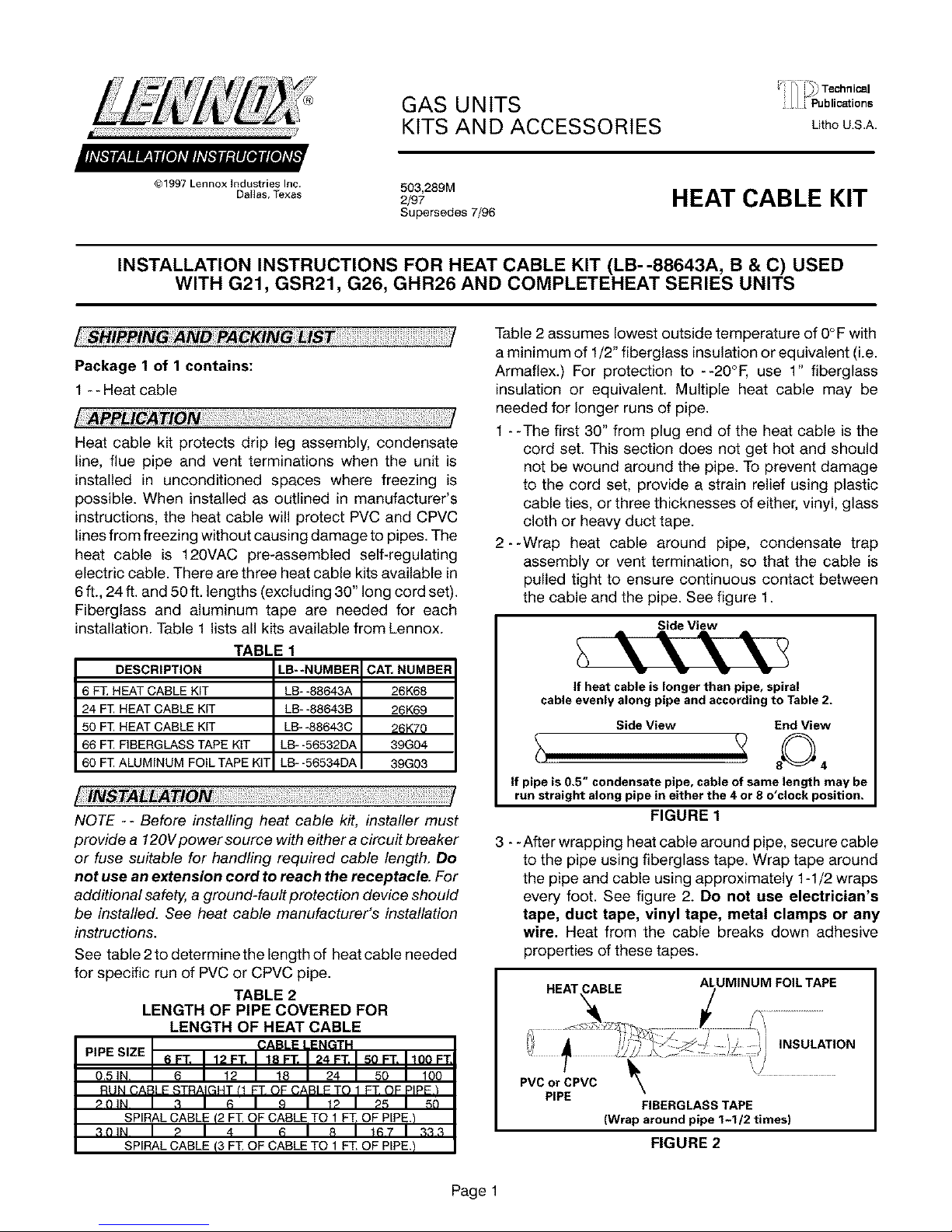
2--Wrap heat cable around pipe, condensate trap
assembly or vent termination, so that the cable is
pulled tight to ensure continuous contact between
the cable and the pipe. See figure 1.
Side View
If heat cable is longer than pipe, spiral
cable evenly along pipe and according toT able 2.
Side View End View
If pipe is 0.5" condensate pipe, cable of same length may be
run straight along pipe in either the 4 or 8 o'clock position.
FIGURE 1
3 - - After wrapping heat cable around pipe, secure cable
to the pipe using fiberglass tape. Wrap tape around
the pipe and cable using approximately 1-1/2 wraps
every foot. See figure 2. Do not use electrician's
tape, duct tape, vinyl tape, metal clamps or any
wire. Heat from the cable breaks down adhesive
properties of these tapes.
HEAT CABLE ALUMINUM FOIL TAPE
• ,,'-',_1_ ' '/•......_I INSULATION
? ,,J'
PVC or CPVC \
PIPE
FIBERGLASS TAPE
(Wrap around pipe 1-1/2 times)
FIGURE 2
Page 1

4--Applyaluminumfoiltapeinlinearstripsoverpipeand
cable.Do not spiral wrap foil tape over pipe. tt may
be necessary to fold one strip up from the bottom and
one strip down from the top of the pipe to ensure
complete coverage. See figure 2.
5--Insulate pipe using fiberglass insulation or
equivalent, i.e. Armaflex. For protection to 0°F use
minimum of 1/2" fiberglass insulation or equivalent
(i.e. Armaflex.) For protection to --20°F, use 1"
fiberglass insulation or equivalent. For protection to
- -40° F,use 1-1/2" fiberglass insulation or equivalent.
See figure 2.
6--Use waterproofing materials such as polyethylene
sheets or other vapor barriers to protect insulation in
areas exposed to moisture (vent termination).
7 - - Refer to figure 3 for G21 condensate trap assembl
G21 CONDENSATE TRAP ASSEMBLY
HEAT CABLE
TRAP
FIBERGLASS
TAPE
*Heat cable can be run
straight on 0.5" condensate
line. See table 2.
DO NOT BLOCK
CLEAN-OUT PLUG
FIGURE 3
8 - -Two methods may be used to apply the heat cable to
concentric vent terminations. See figures 4 and 5.
Figure 4 shows wrapping the heat cable around a
concentric vent termination that has already been
installed. The 24ff. heat cable is recommended for
this method.
CONCENTRIC WALL
TERMINATION APPLICATIONS
EXHAUST CLAMP
\ FIBERGLASS
TAPE "_l_
START OF
CORDSET
EXHAUST
FLUE/
CAP
cable is sufficient for this method. If allowable, this
method is recommended over the first method
because it provides better flue pipe protection.
NOTE-- The waft or roof hole may need to be
enlarged to provide enough clearance for the heat
cable and insulation. The heat cable can be installed
over the mounting clamp or the clamp can be opened
up to provide enough clearance for the heat cable
and insulation.
I
HEAT CABLE for cable. Seal hole after running
__ heat cable Jr.
IMPORTANT J
Drill 1/2" dia. hole in rain shield
1-1/2"
EXHAUST
through
Dr,,,/2"dia.he,oi°iow,°OO°te,Sg°
from air intake connection. Seal hole l /
after running heat cable through it. RAIN
i .o
_/_F-_ AIR INTAKE
FIGURE 5
10- -For the HM30 module of the CompleteHeat system,
spiral wrap the flue trap twice with heat cable before
wrapping the condensate line. See figure 6. Enlarge
condensate line cabinet hole to allow for heat cable
and insulation. Make sure there is enough clearance
between heat cable and cabinet. Protective coating
on heat cable must not be damaged. Do not wrap
the flue trap boot.
HM30 FLUE TRAP
CONDENSATE
LINE*
/
FIBERGLASS
FLUE TRAP
INTAKE
FIGURE 4
9--Figure 5 shows wrapping a concentric vent
termination before it has been installed. The 6 ft.
Page 2
FLUE TRAP BOOT ," ,
i
_IL ..................J *Heat cable can be run
FIGURE 6
FIBERGLASS
TAPE
!
straight on 0.5" condensate
line. See table 2.
 Loading...