

Lennox FCM 100, FCM 170, FCM 120, FCM 150, FCM 200 Installation, Operating And Maintenance
...
Providing indoor climate comfort
FLEXY & FLEXY WSHP
Installation, operating
and maintenance
FLEXYII-WSHP-IOM-0909-E

CONTENTS
FLEXYII_WSHP-IOM-0909-E Page 1
INSTALLATION
OPERATION
MAINTENANCE MANUAL
Ref. FLEXYII_WSHP-IOM-0909-E
The present manual applies to the following ROOFTOP versions:
FCM 85 - FCM 100 - FCM 120 - FCM 150 - FCM 170 - FCM 200 - FCM 230
FHM 85 - FHM 100 - FHM 120 - FHM 150 - FHM 170 - FHM 200 - FHM 230
FDM 85 - FDM 100 - FDM 120 - FDM 150 - FDM 170 - FDM 200 - FDM 230
FGM 85 - FGM 100 - FGM 120 - FGM 150 - FGM 170 - FGM 200 - FGM 230
FWH 85 - FWH 100 - FWH 120 – FWH150 – FWH170
FWM 85 - FWM 100 - FWM 120 – FWM150 – FWM170
FXK 25 - FXK 30 - FXK 35 - FXK 40 - FXK 55 - FXK 70 - FXK 85 - FXK 100 - FXK 110 - FXK 150 - FXK 170
NOTES FOR UNIT FITTED WITH GAS BURNER:
All the technical and technological information contained in this manual, including any drawing and technical descriptions
provided by us, remain the property of Lennox and must not be used (except in operation of this product), reproduced, issued
to or made available to third parts without the prior written agreement of Lennox.
The technical informations and specifications contained in this manual are for reference only. The manufacturer reserves the right to modify
these without warning and without obligation to modify equipment already sold.
THE UNIT MUST BE INSTALLED IN ACCORDANCE WITH LOCAL SAFETY
CODES AND REGULATIONS AND CAN ONLY BE USED IN WELL
VENTILATED AREA.
PLEASE READ CAREFULLY THE MANUFACTURER'S INSTRUCTIONS
BEFORE STARTING THIS UNIT.
THIS MANUAL IS ONLY VALID FOR UNITS DISPLAYING THE FOLLOWING
CODES: GB IR GR DA NO FI IS
In case these symbols are not displayed on the unit, please refer to the technical
documentation which will eventually detail any modifications required to the
installation of the unit in a particular countr
y
.
Switchgear must be installed on each unit in accordance with the Machine
Directive and the standard NF EN 60204.

CONTENTS
FLEXYII_WSHP-IOM-0909-E Page 2
COMMISSIONING SHEET....................................................................................................................................6
INSTALLATION
Transport - Handling.......................................................................................................................................10
Dimensions and weights.................................................................................................................................12
Lifting the units ...............................................................................................................................................14
Preliminary checks .........................................................................................................................................15
Minimum clearance around the unit................................................................................................................16
Duct connections ............................................................................................................................................17
Water connection (water source heat pump)..................................................................................................18
Water loop configuration (water source heat pump) ......................................................................................20
Installation on roof mounting frame ...............................................................................................................22
Curbing and flashing ......................................................................................................................................23
Non-adjustable non-assembled roof curb installation .....................................................................................24
Non-adjustable roof curb - Installation instructions.........................................................................................25
Adjustable roof curb .......................................................................................................................................26
Non-adjustable Non-assembled roof curb .....................................................................................................27
Multidirectional roof curb ...............................................................................................................................28
Return roof curb .............................................................................................................................................29
Return horizontal roof curb .............................................................................................................................30
Transition roof curb.........................................................................................................................................31
Energy Recovery............................................................................................................................................32
Economiser and extraction .............................................................................................................................44
COMMISSIONING
Before connecting the power..........................................................................................................................45
CLIMATIC.......................................................................................................................................................46
Powering the unit............................................................................................................................................46
Run test ..........................................................................................................................................................47
VENTILATION
Belt tension......................................................................................................................................................48
Mounting and adjusting pulleys.......................................................................................................................49
Airflow balancing............................................................................................................... ..............................50
Filters...............................................................................................................................................................58
Air sock control...............................................................................................................................................59
UV Light..........................................................................................................................................................60
HEATING OPTIONS
Hot water coils ...............................................................................................................................................61
Electric heater.................................................................................................................................................63
Gas burners....................................................................................................................................................64
Modulating gas burners ..................................................................................................................................75

CONTENTS
FLEXYII_WSHP-IOM-0909-E Page 3
ELECTRICAL DATA: WIRING DIAGRAMS
Diagram reference legend ..............................................................................................................................84
Main current diagram TRI/400V/50Hz + T……………………………………………………...............................85
CLIMATIC 50 controller………………………………………………………………………….. ............................87
CLIMATIC 50 input…………………………………………………………………………………….......................88
CLIMATIC 50 output…………………………………………………………………………………. .......................89
DAD smoke detector……………………………………………………………………………… ...........................90
General customer connection (TCB) ..............................................................................................................91
General customer connection with Advanced Control Pack (ADC) ................................................................92
Gas burner 60 kW and hot water coil .............................................................................................................93
Gas burner 120 kW ........................................................................................................................................94
Gas burner 180/240 kW..................................................................................................................................95
Electric heater.................................................................................................................................................96
General customer connection diagram...........................................................................................................97
Electrical data control variables ......................................................................................................................98
REFRIGERATION CIRCUIT
R410A ............................................................................................................................................................99
Advanced scroll temperature protection (ASTP).............................................................................................100
Principle sketches...........................................................................................................................................101
HOT WATER COIL DIAGRAM .............................................................................................................................107
MAINTENANCE DIAGNOSTIC
.............................................................................................................................108
MAINTENANCE PLAN
.........................................................................................................................................112
WARRANTY
..........................................................................................................................................................115
CERTIFICATES
....................................................................................................................................................116

IMPORTANT NOTICE – Safety instructions
FLEXYII_WSHP-IOM-0909-E Page 4
All FLEXY II Units are compliant with the PED directive 97-23/CE
The following note must be followed carefully
All work on the unit must be carried out by a qualified and authorised employee.
Non-compliance with the following instructions may result in injury or serious accidents.
Work on the unit:
• The unit shall be isolated from the electrical supply by disconnection and locking using the main isolating switch.
• Workers shall wear the appropriate personal protective equipment (helmet, gloves, glasses, etc.).
Work on the electrical system:
• Work on electric components shall be performed with the power off by employees having valid electrical qualification and
authorisation.
Work on the refrigerating circuit(s):
• Monitoring of the pressures, draining and filling of the system under pressure shall be carried out using connections provided
for this purpose and suitable equipment.
• To prevent the risk of explosion due to spraying of coolant and oil, the relevant circuit shall be drained and at zero
pressure before any disassembly or unbrazing of the refrigerating parts takes place.
• There is a residual risk of pressure build-up by degassing the oil or by heating the exchangers after the circuit has been
drained. Zero pressure shall be maintained by venting the drain connection to the atmosphere on the low pressure side.
• The brazing shall be carried out by a qualified brazier. The brazing shall comply with standard NF EN1044 (minimum 30%
silver).
Replacing components:
• In order to maintain CE marking compliance, replacement of components shall be carried out using spare parts, or using
parts approved by Lennox.
• Only the coolant shown on the manufacturer’s nameplate shall be used, to the exclusion of all other products (mix of
coolants, hydrocarbons, etc.).
CAUTION:
In the event of fire, refrigerating circuits can cause an explosion and spray coolant gas and oil.
TRANSPORT – HANDLING:
- Never lift the unit without forklift protections
- Remove the forklift protection before installation
- An approach ramp must be installed if the unit’s installation requirements tell that it's necessary to reach the main switch.
This recommendation is valid for installations in general and in particular for return and curbs. It’s also valid to reach other parts
of the unit: filters, refrigerant circuit, etc…
- It’s advised to fix curbs and roofcurbs to the unit
- Whatever the supply configuration is, respect a minimal duct’s length of 2m before any elbow or any duct’s section change.
COMMISSIONING:
- It must only be carried out by trained refrigeration engineers.
- Don’t forget to open the insulation valve on the liquid line before starting the unit
FILTERS:
- Do the filters fire classification’s choice according to local regulations.
FANSTART:
- Any adjustment has to be done power stopped.
GAS:
- Any work on gas module must be carried out by qualified personnel
- A unit with gas module must be installed in accordance with local safety codes and regulations and can only be used in
planed installation conditions for outdoor.
- Before commissioning this type of unit, it’s mandatory to ensure that the gas distribution system is compatible with the
adjustment and settings of the unit.
IMPORTANT NOTICE – Safety instructions
FLEXYII_WSHP-IOM-0909-E Page 5
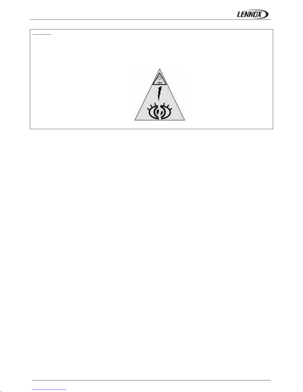
UV LIGHT :
- The UV lamp emits shortwave UV-C ultraviolet radiation which is harmful to skin and eyes
- It can cause serious skin burns and eye inflammation within ONE SECOND of exposure
- Do not enter the machine while UV are switched on
- Make sure the UV light circuit breaker is OFF when opening the return air section door and the supply air section doors
- The following logo will appear to inform about the UV-C radiation risk
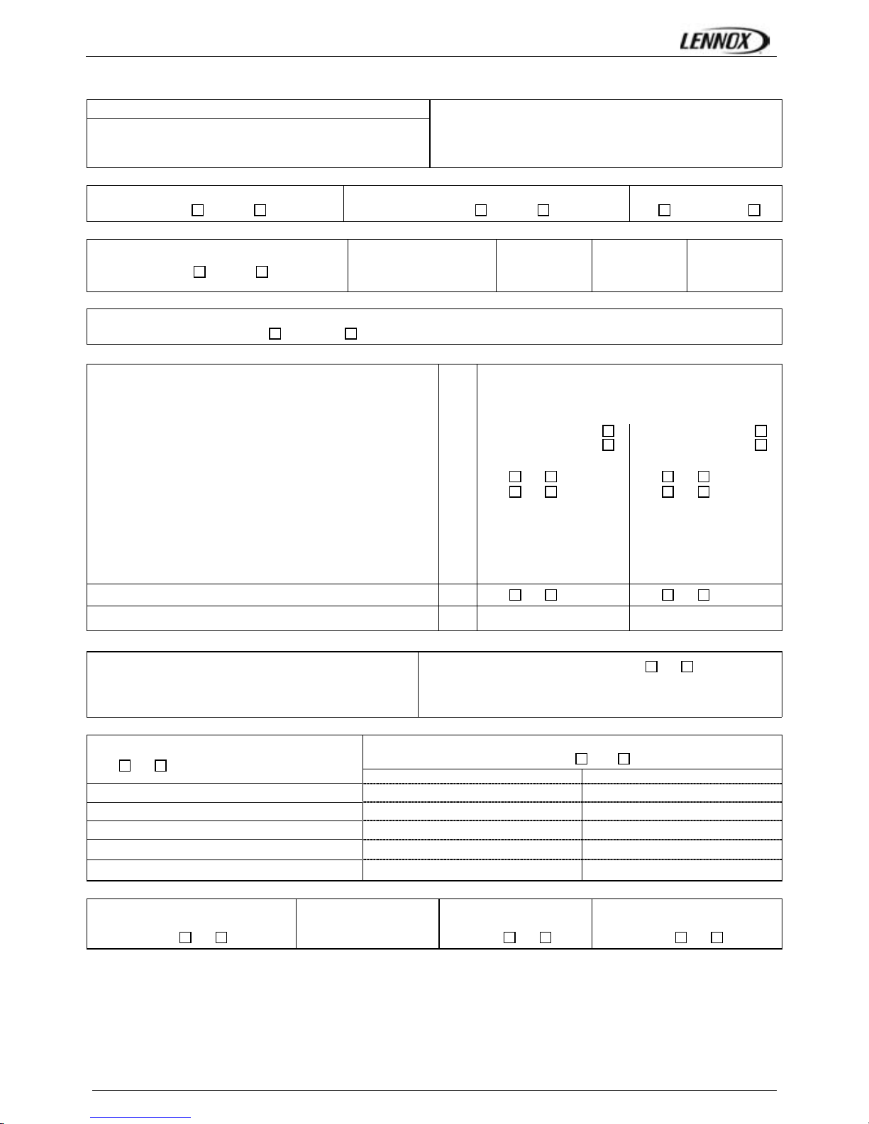
COMMISSIONNING REPORT
FLEXYII_WSHP-IOM-0909-E Page 6
Site details
Site
Unit Ref
Installer
………………………………………
……………………………………....
………………………………………
Controller
Model
Serial No
Refrigerant
………………………………….
……………….…………………
…………………………………
…………………………………
(1) ROOF INSTALLATION
Sufficient Access OK
Yes
No
Condensate drain fitted
Yes No
Roofcurb
OK Not OK
(2) CONNECTIONS CHECK
Phase check
Yes
No
Voltage between Phases
1 / 2
……………….
2 / 3
……………….
1 / 3
……………….
(3)CLIMATIC CONFIGURATION CHECK
CLIMATIC 50 Configured according to the Options and Specifications:
Yes
No
(4) SUPPLY BLOWER SECTION
Type :
Power displayed on plate:
Voltage displayed on plate:
Current displayed on plate:
KW
V
A
N°1
……………………
……………………
……………………
N°2
……………………
……………………
……………………
Fan Type : Forward
Backward
Forward
Backward
Displayed Belt Length : mm …………………… ……………………
Tension Checked: Yes No Yes No
Alignment Checked : Yes No Yes No
Motor Pulley Diameter: DM mm …………………… ……………………
Fan Pulley Diameter: DP mm …………………… ……………………
Fan Speed = Motor rpm x DM / DP
Averaged Measured Amps :
rpm
A
……………………
……………………
……………………
……………………
Shaft Mechanical Power (Refer to airflow balancing) W …………………… ……………………
Operating point checked : Yes No Yes No
Estimated Airflow
m3/h
…………………… ……………………
(5) AIRFLOW PRESS. SENSOR CHECK
Measured pressure drop…………………………… mbar
Set Points Adjusted: Yes
No
If Yes enter new values:
3410: ………… 3411: ………… 3412: …………
(6) EXTERNAL SENSOR CHECKS
Check and record temp. in menu 2110
Yes
Non
Check electrical connections :
Yes
No
100% Fresh Air 100% return Air
Supply Temperature ………………………..°C ………………………..°C
Return Temperature ………………………..°C ………………………..°C
Outdoor Temperature ………………………..°C ………………………..°C
Inlet Water Temp. (for Water Condensing) ………………………..°C ………………………..°C
Outlet Water Temp. (for Water Condensing) ………………………..°C ………………………..°C
(7) MIXING AIR DAMPERS CHECKS
Dampers open & close freely
OK
% Minimum FA: Power exhaust checked Enthalpy sensor(s) checked
Yes No ……………..% Yes No Yes No
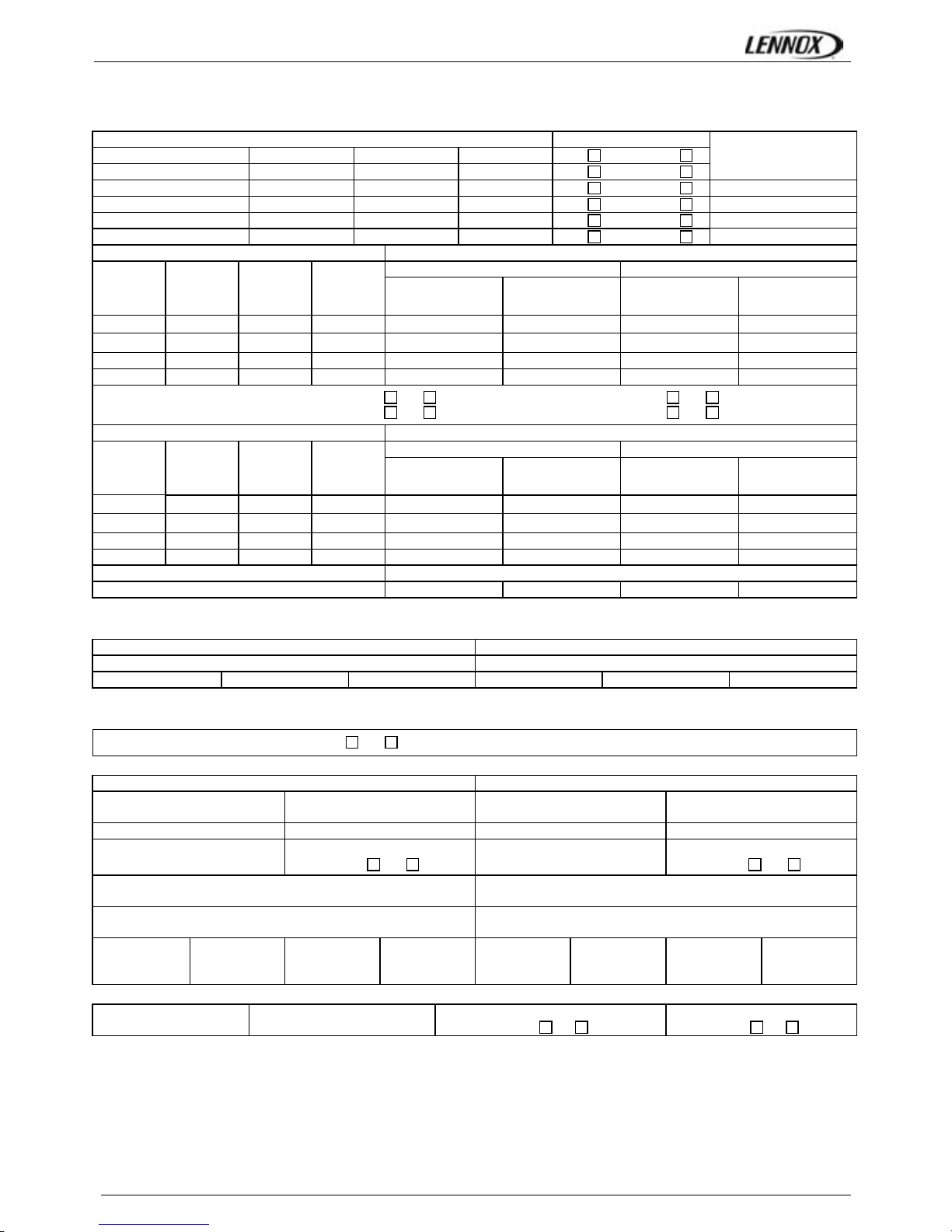
COMMISSIONNING REPORT
FLEXYII_WSHP-IOM-0909-E Page 7
(8) REFRIGERATION SECTION
Outdoor Fan Motor Current: Check Rotation
Motor 1 / Moteur 1 L1 ……..A L2 ……..A L3 ……A Yes No
Motor 2 / Moteur 2 L1 ……..A L2 ……..A L3 ……A Yes No
Compressor Voltage
Motor 3 / Moteur 3 L1 ……..A L2 ……..A L3 ……A Yes No Comp1: …….. V
Motor 4 / Moteur 4 L1 ……..A L2 ……..A L3 ……A Yes No Comp2: …….. V
Motor 5 / Moteur 5 L1 ……..A L2 ……..A L3 ……A Yes No Comp3: …….. V
Motor 6 / Moteur 6 L1 ……..A L2 ……..A L3 ……A Yes No Comp4: …….. V
Compressor Amps COOLING Pressures & Temperatures
Temperatures Pressures
Phase 1 Phase 2 Phase 3
Suction
Discharge
LP/ BP
HP / HP
Comp 1 …..… A …..… A …..… A ……… °C ……… °C ……… Bar ……… Bar
Comp 2 …..… A …..… A …..… A ……… °C ……… °C ……… Bar ……… Bar
Comp 3 …..… A …..… A …..… A ……… °C ……… °C ……… Bar ……… Bar
Comp 4 …..… A …..… A …..… A ……… °C ……… °C ……… Bar ……… Bar
Check Reversing valves :
Valve1: Yes
No
Valve2: Yes
No
Valve3: Yes
No
Valve4: Yes
No
Compressor Amps HEATING Pressures & Temperatures
Temperatures Pressures
Phase 1 Phase 2 Phase 3
Suction
Discharge
LP/ BP
HP / HP
Comp 1 …..… A …..… A …..… A ……… °C ……… °C ……… Bar ……… Bar
Comp 2 …..… A …..… A …..… A ……… °C ……… °C ……… Bar ……… Bar
Comp 3 …..… A …..… A …..… A ……… °C ……… °C ……… Bar ……… Bar
Comp 4 …..… A …..… A …..… A ……… °C ……… °C ……… Bar ……… Bar
HP cut out ……Bar LP cut out ………..…... Bar
Refrigerant charge C1 : ………..kg C2 : ………..kg C3 : ………..kg C4 : ………..kg
(8)ELECTRIC HEATER SECTION
Type : …………………………………………………. Serial No.:………………………..
AMPS 1st stage (Baltic) AMPS 2nd stage (Baltic)
1 ………………. 2 ………………. 3 ………………. 1 ………………. 2 ………………. 3 ……………….
(9) HOT WATER COIL SECTION
Check Three Way Valve Movement : Yes No
(10) GAS HEATING SECTION
Gas Burner N°1 Gas Burner N°2
Size :
……………………….
Valve type :
…………………….
Size :
……………………….
Valve type :
…………………….
Pipe size:
Gas type : G…….
Pipe size
Gas type : G…….
Line pressure :
………………………
Drop test
Yes No
line pressure :
………………………
Drop test
Yes No
Check manifold pressure:
High fire …….…Low fire ………..
Check manifold pressure:
High fire …….…... Low fire ………..
Pressure cut out airflow press switch :
……………………mbar /Pa
Pressure cut out airflow press switch :
……………………mbar /Pa
Motor amps :
……….A
Flue temp.
……… °C
CO2 %:
………%
CO ppm:
………%
Motor Amps:
……….A
Flue temp.
………. °C
CO2 %:
………%
CO ppm:
………%
(11) REMOTE CONTROL BMS CHECK
Type :
…………………………..
Sensor type
………………………………..
KP07 KP/17 checked:
Yes No
Interconnect wiring checked:
Yes No
COMMISSIONNING REPORT
FLEXYII_WSHP-IOM-0909-E Page 8
It is recommended that you fill the two tables below before transferring the zone settings to the Climatic 50 controller.
Refer to control section page 55 / Se référer à la section régulation page 55
Time Zones / Zones Horaires
Hour
0 1 2 3 4 5 6 7 8 9 10 11 12 13 14 15 16 17 18 19 20 21 22 23
Example
UNO
7h15
ZA
11h00
ZB
14h00
ZC
19h00
UNO
Monday
Tuesday
Wednesday
Thursday
Friday
Saturday
Sunday
Variables to adjust for each time zone / Consignes à renseigner pour chaque zone horaire
Start z.A Start z.B Start z.C Start UNO
hour (3211) min (3212) hour (3213) min (3214) hour (3215) min (3216) hour (3217) min (3218)
Monday
Tuesday
Wednesday
Thursday
Friday
Saturday
Sunday
Description Unit Menu Min
Max
Zone A Zone B Zone C UNOC
Sp Room °C 3311 8 35
Mini.Air % 3312 0 100
Sp Dyna °C 3321 0 99.9
Sp Cool °C 3322 8 35
Sp Heat °C 3323 8 35
Swap Heater On/Off 3324 ~ ~
Activation On/Off 3331 ~ ~
Swap Heater On/Off 3332 ~ ~
Sp.Dehu % 3341 0 100
Sp.Humi % 3342 0 100
Fan On/Off On/Off 3351 ~ ~
Fan Dead On/Off 3352 ~ ~
F.Air On/Off 3353 ~ ~
CO2 On/Off 3354 ~ ~
Comp.Cool. On/Off 3355 ~ ~
Comp.Heat. On/Off 3356 ~ ~
AuxHeat On/Off 3357 ~ ~
Humidif. On/Off 3358 ~ ~
Low Noise On/Off 3359 ~ ~ N/A N/A N/A

COMMISSIONNING REPORT
FLEXYII_WSHP-IOM-0909-E Page 9
COMMENTS:
.......................................................................................................................................................................................................
.......................................................................................................................................................................................................
.......................................................................................................................................................................................................
.......................................................................................................................................................................................................
.......................................................................................................................................................................................................
.......................................................................................................................................................................................................
............. ………….……………………………………………………………………………………………………………………………...
.......................................................................................................................................................................................................
.......................................................................................................................................................................................................
.......................................................................................................................................................................................................
.......................................................................................................................................................................................................
.......................................................................................................................................................................................................
.......................................................................................................................................................................................................
.......................................................................................................................................................................................................
.......................................................................................................................................................................................................
.......................................................................................................................................................................................................
.......................................................................................................................................................................................................
.......................................................................................................................................................................................................
.......................................................................................................................................................................................................
.......................................................................................................................................................................................................
.......................................................................................................................................................................................................
.......................................................................................................................................................................................................
.......................................................................................................................................................................................................
.......................................................................................................................................................................................................
.......................................................................................................................................................................................................
.......................................................................................................................................................................................................
.......................................................................................................................................................................................................
.......................................................................................................................................................................................................
.......................................................................................................................................................................................................
.......................................................................................................................................................................................................
.......................................................................................................................................................................................................
.......................................................................................................................................................................................................
.......................................................................................................................................................................................................

TRANSPORT – HANDLING – WARNING
FLEXYII_WSHP-IOM-0909-E Page 10
DELIVERY CHECKS
On receipt of a new equipment please check the following
points. It is the customer’s responsibility to ensure that the
products are in good working order:
- The exterior has not been damaged in any way.
- The lifting and handling equipment are suitable for the
equipment and comply with the specifications of the
handling instructions enclosed here-in.
- Accessories ordered for on site installation have been
delivered and are in good working order.
- The equipment supplied corresponds to the order and
matches the delivery note.
If the product is damaged, exact details must be confirmed
in writing by registered post to the shipping company within
48 hours of delivery (working days). A copy of the letter
must be addressed to Lennox and the supplier or
distributor for information purposes. Failure to comply will
invalidate any claim against the shipping company.
RATING PLATE
The rating plate provides a complete reference for the
model and ensures that the unit corresponds to the model
ordered. It states the electrical power consumption of the
unit on start-up, its rated power and its supply voltage. The
supply voltage must not deviate beyond +10/-15 %. The
start-up power is the maximum value likely to be achieved
for the specified operational voltage. The customer must
have a suitable electrical supply. It is therefore important to
check whether the supply voltage stated on the unit's rating
plate is compatible with that of the mains electrical supply.
The rating plate also states the year of manufacture as well
as the type of refrigerant used and the required charge for
each compressor circuit.
Fig. 1
STORAGE
When units are delivered on site they are not always
required immediately and are sometimes put into storage.
In the event of medium to long-term storage, we
recommend the following procedures:
- Ensure that there is no water in the hydraulic systems.
- Keep the heat exchanger covers in position (AQUILUX cover).
- Keep protective plastic film in position.
- Ensure the electrical panels are closed.
- Keep all items and options supplied in a dry and clean
place for future assembly before using the equipment.
MAINTENANCE KEY
On delivery we recommend that you keep the key which is
attached to an eyebolt in a safe and accessible place. This
allows you to open the panels for maintenance and
installation work.
The locks are ¼ turn + then tighter (figure 2).
CONDENSATE DRAINS
The condensate drains are not assembled when delivered
and are stored
in the electrical panel with their clamping collars.
To assemble them, insert them on the condensate tray outlets
and use a screwdriver to tighten the collars (Figure 3).
Fig. 3

TRANSPORT – HANDLING
FLEXYII_WSHP-IOM-0909-E Page 11
Handling slings to guide the
unit towards the roofcurb
Vacuum lifting beam to
position the unit
COMPLIAN
T
NON-COMPLIAN
T
TRANSPORT – HANDLING
FLEXYII_WSHP-IOM-0909-E Page 12
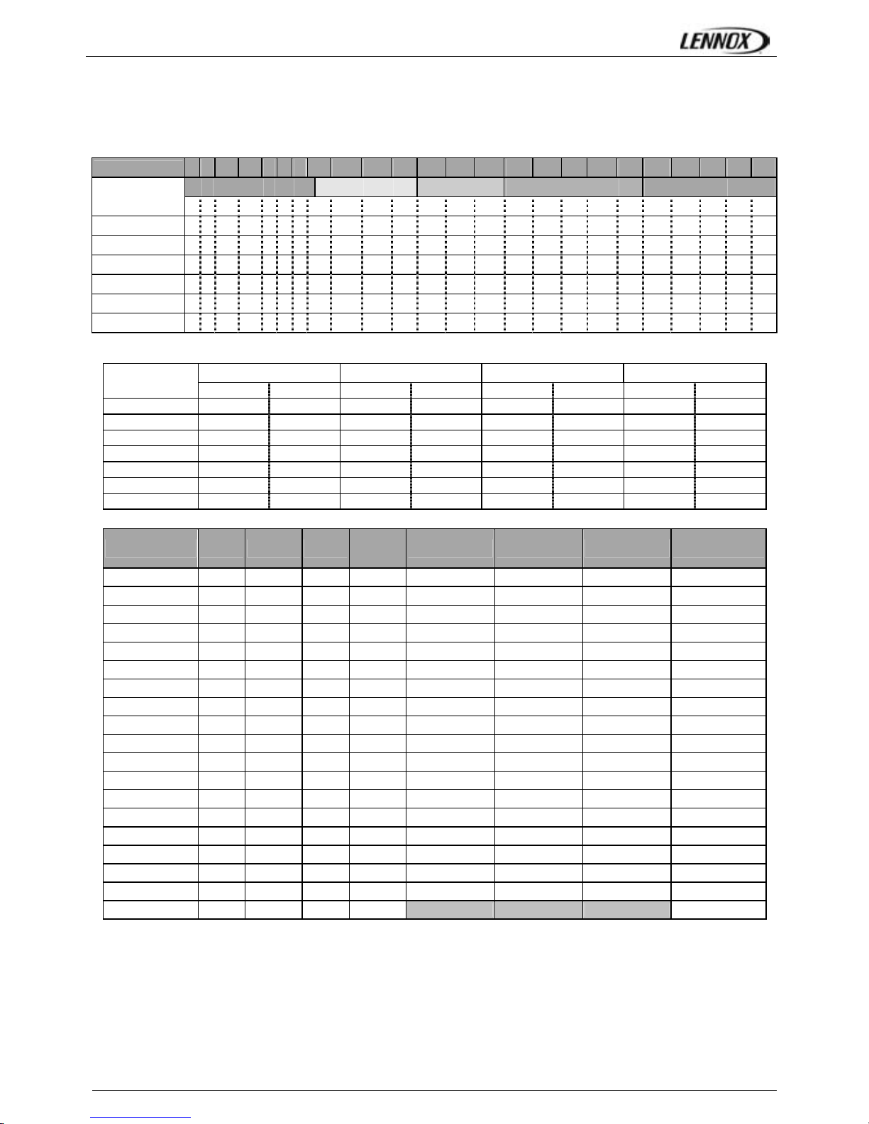
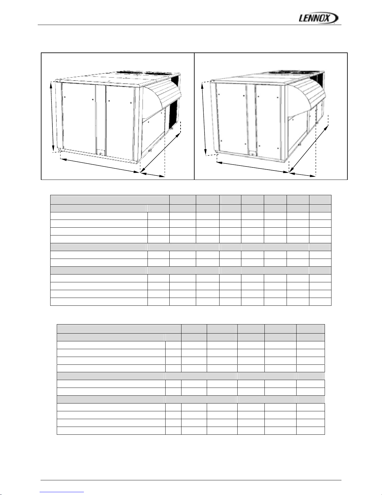
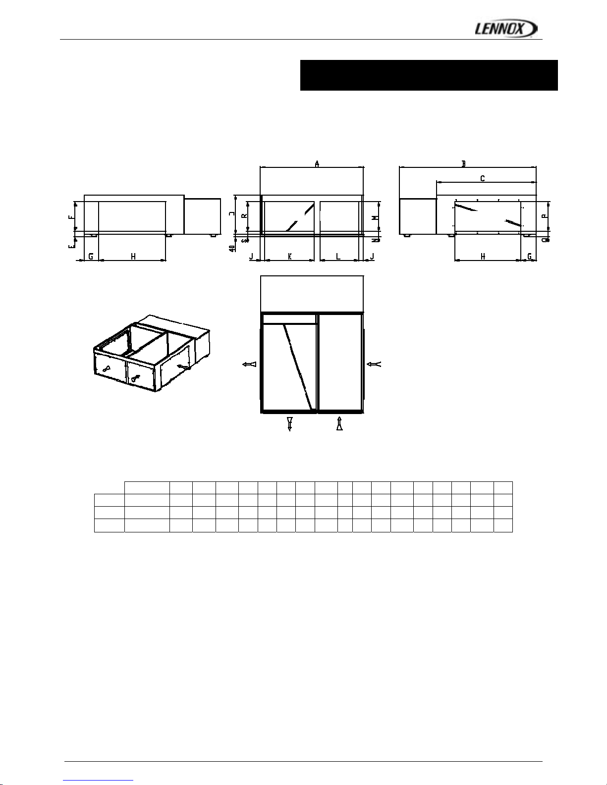
DIMENSIONS AND WEIGHTS
FLEXY2 FCM/FHM/FGM/FDM
85 100 120 150 170 200 230
View (F, G, H box)
F BOX F BOX F BOX G BOX G BOX H BOX H BOX
A
mm 2200 2200 2200 2200 2200 2200 2200
B
mm 3350 3350 3350 4380 4380 5533 5533
C
mm 1510 1510 1510 1834 1834 2134 2134
D
mm 360 360 360 450 450 615 615
Weight of standard units FCM
Without economiser kg 934 1009 1085 1367 1430 1650 1950
With economiser kg 990 1065 1141 1442 1505 1752 2052
Weight gas unit FGM
Standard heat Without economiser kg 1041 1116 1192 1608 1671 1914 2214
Standard heat With economiser kg 1097 1172 1248 1683 1746 2016 2316
High heat without economiser kg 1111 1186 1262 1631 1694 1954 2254
High heat With economiser kg 1167 1242 1318 1706 1769 2056 2356
WSHP FWH/FWM
85 100 120 150 170
View (F & G box)
F BOX F BOX F BOX G BOX G BOX
A
mm 2200 2200 2200 2200 2200
B
mm 3350 3350 3350 4380 4380
C
mm 1510 1510 1510 1834 1834
D
mm 360 360 360 450 450
Weight of standard units FWH
Without economizer kg 797 883 969 1250 1313
With economizer kg 853 939 1026 1325 1388
Weight gas unit FWM
Standard heat Without economiser kg 904 990 1076 1491 1554
Standard heat With economiser kg 960 1046 1133 1566 1629
High heat without economiser kg 974 1060 1146 1514 1577
High heat With economiser kg 1030 1116 1203 1589 1652
F & G BOX H BOX
A
D
B
C
D
A
B
C
TRANSPORT – HANDLING
FLEXYII_WSHP-IOM-0909-E Page 13
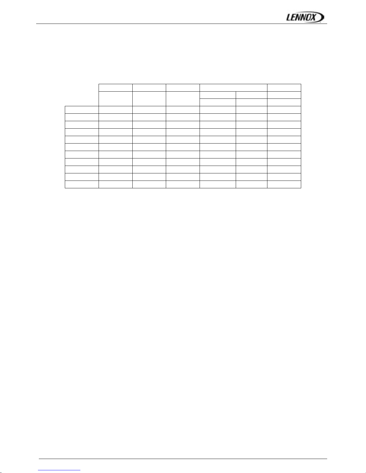
DIMENSIONS AND WEIGHTS
LENGTH HEIGHT WIDTH HOOD WEIGHT
Side Fan Standard
mm mm mm
mm mm kg
FXK025 4070 1635 1055 490 600 950
FXK030 4070 1635 1055 490 600 980
FXK035 4750 2255 1290 490 600 1400
FXK040 4750 2255 1290 490 600 1450
FXK055 4750 2255 1290 490 600 1600
FXK070 5050 2255 1725 890 600 1800
FXK085 5050 2255 1725 890 600 1900
FXK100 5050 2255 1725 890 600 2000
FXK110 5650 2255 2000 860 - 2620
FXK140 5650 2255 2000 860 - 2620
FXK170 5650 2255 2000 860 - 2650
TRANSPORT – HANDLING
FLEXYII_WSHP-IOM-0909-E Page 14
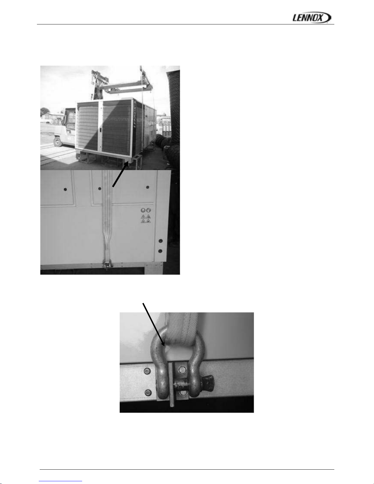
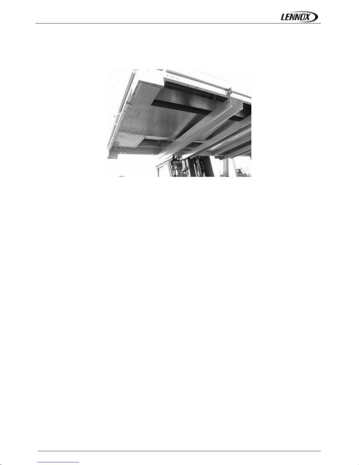
LIFTING THE UNIT
As shown on the picture below, a lifting frame is necessary.
After lifting, withdraw angle’s feet and lifting lugs.
INSTALLATION
FLEXYII_WSHP-IOM-0909-E Page 15
FORKLIFT PROTECTIONS
NEVER LIFT THE UNIT WITHOUT FORKLIFT PROTECTIONS
REMOVE THE FORKLIFT PROTECTIONS
BEFORE INSTALLATION
PRELIMINARY CHECKS
Before installing the equipment, the following points MUST
be checked:
- Have the forklift protections been removed?
- Is there sufficient space for the equipment?
- Is the surface on which the equipment is to be
installed sufficiently solid to withstand its weight? A
detailed study of the frame must be made beforehand.
- Do the supply and return ductwork openings
excessively weaken the structure?
- Are there any obstructing items which could hinder the
operation of the equipment?
- Does the electrical power available correspond to the
equipment's electrical specifications?
- Is drainage provided for the condensate?
- Is there sufficient access for maintenance?
- Installation of the equipment could require different
lifting methods which may vary with each installation
(helicopter or crane). Have these been evaluated?
- Ensure that the unit is installed in accordance with the
installation instructions and local applicable codes.
- Check to ensure that the refrigerant lines do not rub
against the cabinet or against other refrigerant lines.
In general, make sure no obstacles (walls, trees or roof
ledges) are obstructing the duct connections or hindering
assembly and maintenance access.
INSTALLATION REQUIREMENTS
The surface on which the equipment is to be installed must
be clean and free of any obstacles which could hinder the
flow of air to the condensers:
-Avoid uneven surfaces
-Avoid installing two units side by side or close to each
other as this may restrict the airflow to the condensers.
Before installing a packaged Rooftop unit it is important to
understand:
- The direction of prevailing winds
-The direction and position of air flows.
-The external dimensions of the unit and the
dimensions of the supply and return air connections.
-The arrangement of the doors and the space required
to open them to access the various components.
CONNECTIONS
-Ensure that all the pipe-work crossing walls or roofs
are secured, sealed and insulated.
-To avoid condensation problems, make sure that all
pipes are insulated according to the temperatures of
fluids and type of rooms.
NOTE: The AQUILUX protection sheets fitted to the finned
surfaces must be removed prior to start up.
INSTALLATION
FLEXYII_WSHP-IOM-0909-E Page 16
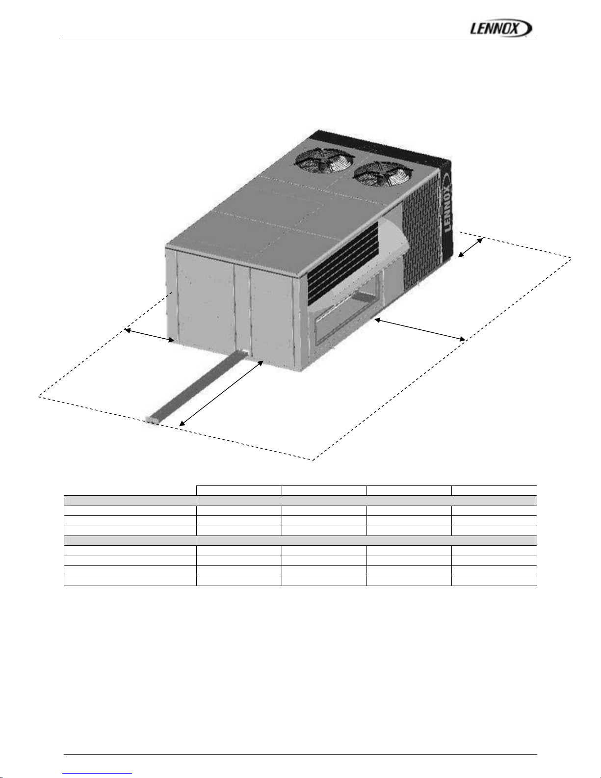
MINIMUM CLEARANCE AROUND THE UNIT
Figure 4 shows the required clearances and service access around the unit.
NOTE: Ensure the fresh air inlet does not face prevailing wind direction.
A B C D
FCM/FHM/FGM/FDM/FWH/FWM
F BOX
2200
(1)
2000 2000 2000
G BOX
2700
(1)
2000 2000 2000
H BOX
2700
(1)
2000 2000 2000
FX
25 & 30
* 1100 * 1700
35Æ55
* 1300 * 2300
70Æ100
* 1700 * 2300
110Æ170
* 2000 * 2300
(1) Add 1 meter if the units are equipped with gas burner
A
B
C
D
DUCT CONNECTIONS
FLEXYII_WSHP-IOM-0909-E Page 17
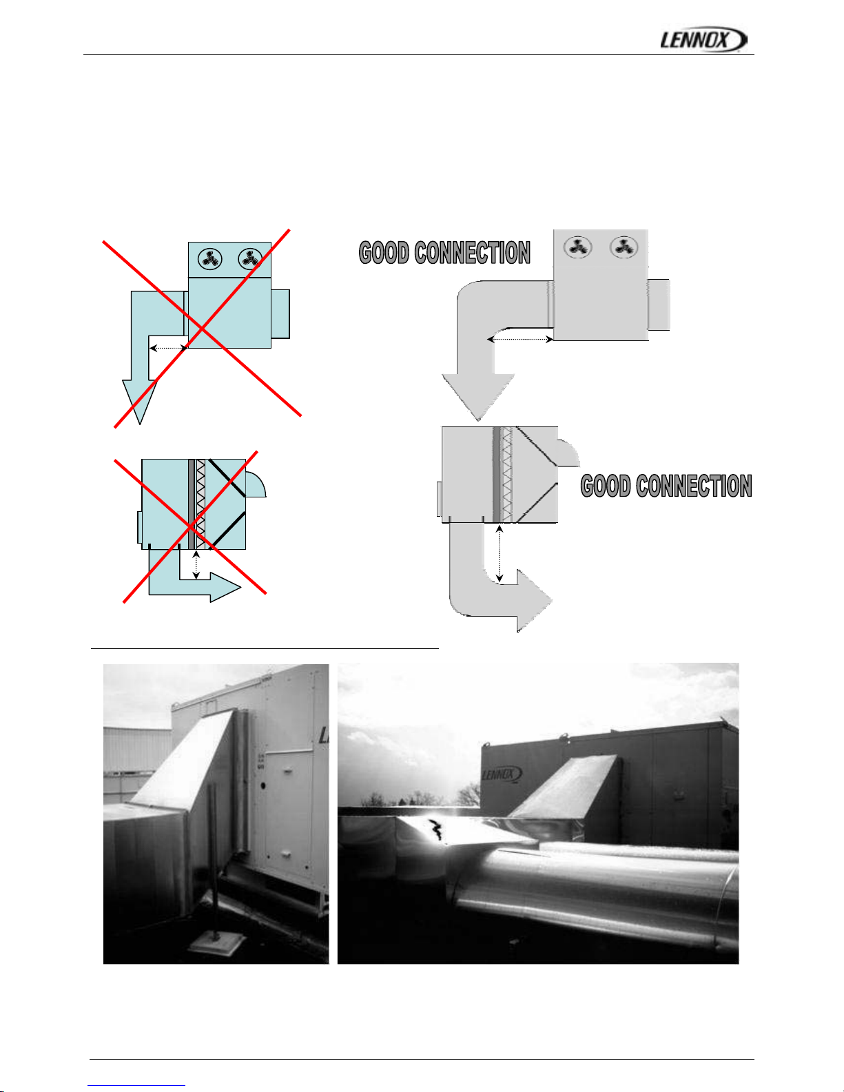
RECOMMENDATIONS FOR DUCTS CONNECTIONS
Some rules must be complied with for the connections between ducts and unit done on site.
Whatever the supply configuration is, respect a minimal duct’s length (D) of 2m before any elbow or any duct’s diameter
change.
These recommendations are imperative in the case of 2 independent turbines (sizes from 150kW to 230kW and all units
equipped with gas module)
Horizontal supply
Vertical supply
Here are obvious bad examples of ducts connections noted on site:
D ≥ 2m
D ≥ 2m
D ≤ 2m
D ≤ 2m

WATER CONNECTIONS
FLEXYII_WSHP-IOM-0909-E Page 18
WATER SOURCE HEAT PUMP ONLY
Water connections
The water circulating pump will be preferably installed upstream so that the evaporator/condenser will be subjected to positive
pressure. Inlet and Outlet water connections are indicated on the certified drawing sent with the unit or shown in the sales
brochure.
The water pipes connected to the unit must not transmit any radial or axial force or any vibration to the heat exchangers.
It is important to follow non exhaustive recommendations hereunder:
• Comply with the water inlet and outlet connections shown on the unit.
• Install manual or automatic air purge valves at all high points in the circuit.
• Install a safety valve as well as an expansion tank to maintain the circuit pressure.
• Install thermometers in both the inlet and outlet water connections.
• Install drain connections at all low points to allow the whole circuit to be drained.
• Install stop valves, close to the inlet and outlet water connections.
• Use flexible connections to reduce vibrations transmission.
• After testing for leaks, insulate all pipe work, to reduce thermal leaks and to prevent condensation.
• If the external water pipes are in an area, where the ambient temperature is likely to fall below 0°C, insulate the piping and
add an electric heater.
• Ensure full earthling continuity
A drainage plug is located at the base of the evaporator. A drainage pipe may be connected to this to enable drainage of
evaporator water for service operations or for seasonal shut down.
Connections at the inlet and outlet are Victaulic type.
Water analysis
The water must be analysed; the water circuit installed must include all items necessary for water treatment: filters, additives,
intermediate exchangers, bleed valves, vents, isolating valves etc... depending on the results of the water analysis.
We do not advise operation of the units with open loops which can cause troubles with oxygenation, or
operation with untreated ground water.
Use of untreated or improperly treated water can cause deposits of scale, algae and sludge or cause corrosion and erosion. It is
advisable to call in a qualified water treatment specialist to determine what kind of treatment will be necessary. The
manufacturer cannot accept liability for damage caused by the use of untreated or improperly treated water, salt water or brine.
Here are our non exhaustive recommendations given as an indication:
• No NH4+ ammonium ions in the water, they are very detrimental for copper. <10mg/l
• Cl- Chloride ions are detrimental for copper with a risk of perforations by corrosion by puncture. < 10 mg/l.
• SO42- sulphate ions can cause perforating corrosion.< 30 mg/l.
• No fluoride ions (<0.1 mg/l).
• No Fe2+ and Fe3+ ions with dissolved oxygen. Dissolved iron < 5 mg/l with dissolved oxygen < 5 mg/l. Over
those values, it means a corrosion of steel which may generate a corrosion of copper parts under deposite of Fe – this is
mainly the case with shell and tube heat exchangers.
• Dissolved silicon: silicon is an acid element of water and can also lead to corrosion risks. Content < 1mg/l.
• Water hardness: TH >2.8 K. Values between 10 and 25 can be recommended. This will facilitate scale deposit that can limit
corrosion of copper. TH values that are too high can cause piping blockage over time.
• TAC< 100.
• Dissolved oxygen: Any sudden change in water oxygenation conditions must be avoided. It is as detrimental to
deoxygenate the water by mixing it with inert gas as it is to over-oxygenate it by mixing it with pure oxygen. The disturbance
of the oxygenation conditions encourages destabilisation of copper hydroxides and enlargement of particles.
• Specific resistance – electric conductivity: the higher the specific resistance, the slower the corrosion tendency. Values
above 3000 Ohm/cm are desirable. A neutral environment favours maximum specific resistance values.
For electric conductivity values in the order of 200-6000 S/cm can be recommended.
• pH: pH neutral at 20°C (7 < pH < 8)
WATER CONNECTIONS
FLEXYII_WSHP-IOM-0909-E Page 19
Antifreeze protection
Use glycol/water solution
ADDITION OF GLYCOL IS THE ONLY EFFICIENT WAY TO PROTECT AGAINST FREEZING
The glycol/water solution must be sufficiently concentrated to ensure proper protection and prevent formation of
ice at the lowest outdoor air temperatures expected on an installation. Take precautions when using non
passivated MEG antifreeze solutions (Mono Ethylene Glycol or MPG Mono Propylene Glycol). Corrosion can
occur with these antifreeze solutions with oxygen.
Drain the installation
To enable drainage of the circuit, make sure that drain cocks are installed at all the low points of the circuit.
To drain the circuit, the drain cocks must be opened and an air inlet ensured.
Note : air bleeders are not designed to admit air.
EVAPORATOR FREEZING DUE TO COLD WEATHER CONDITIONS IS NOT COVERED BY LENNOX
WARRANTY.
Minimum water content
The minimum volume of the rooftop water circuit must be determined. If necessary, install a buffer tank. Proper operation of
regulating and safety devices can only be ensured if the volume of water is sufficient.
The theoretical volume of the water loop for a proper air conditioning operation can be calculated using the formulas hereafter:
WATER COOLED FLEXYII RANGE
Vt Æ Minimum water content of the installation
Q Æ Water capacity in kW
N Æ Number of control steps available in the unit
Dt Æ Maximum acceptable temperature rise (Dt = 6°c for an air conditioning application)
Vmini = 86 x Q / (N x Dt)
Unit Size
Number of
stages
Mini Water
Volume (L)
FWH/FWM 085
FWH/FWM 100
FWH/FWM 120
FWH/FWM 150
FWH/FWM 170
2
2
2
3
4
631
781
867
702
627
WATER CONDENSING
FLEXYII_WSHP-IOM-0909-E Page 20
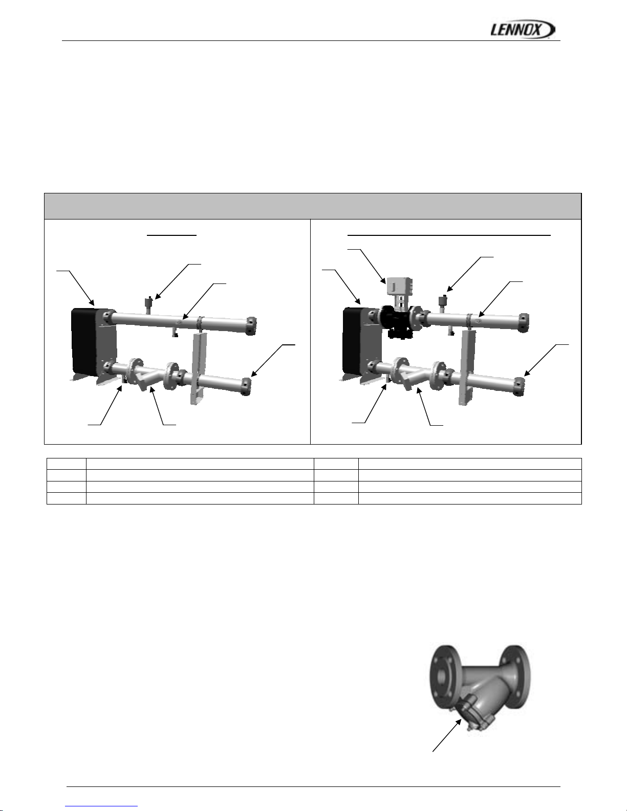
WATER LOOP CONFIGURATION (FOR WATER SOURCE HEAT PUMP)
Figures below show the 2 water configurations.
Figure 1 indicates all components used as standard :
• the electronic water flow switch,
• the water filter,
• the pressure taps and drain valves,
• the automatic airvent,
The second figure shows rooftop water loop with Low Water Loop Temperature option.
LOW WATER LOOP TEMPERATURE (OPTION)
In order to operate with low water inlet temperature in cooling mode (ie: ground source water loops) it is necessary to control
the water flow rate in the heat exchanger to maintain a minimum condensing pressure in the refrigeration circuit.
In cooling mode the climatic 50 will control the water flow rate in the condenser by monitoring the condensing pressure and by
closing the water flow valve accordingly by a 0-10 Volts signal.
This option offers a second opportunity: give the possibility to close the rooftop water loop when compressors are stopped.
WATER FILTER REPLACEMENT (ONLY FOR WAT ER SOURCE HEAT PUMP)
It is important that units are serviced regularly by a qualified technician, at least
once every year or every 1000 hours of operation.
CAUTION: The water circuit may be pressurised. Observe the usual
precautions when depressurising the circuit before opening it. Failure to
observe these rules could lead to accidents and cause injury to service
personal.
1
All Victaulic Connections
5
Pressure Taps and drain Valve
2
Inlet Water Filter
6
Stainless steel Exchanger
3
Automatic Air Vent
7
ElectroValve (HP control option)
4
Electronic Flow Switch
2
1
3
4
5
6
1
2
3
4
5
6
7
Low Water Loop Temperature Option
Hydraulic Data
Standard
Access for cartridge cleaning
Figure 1 Figure 2
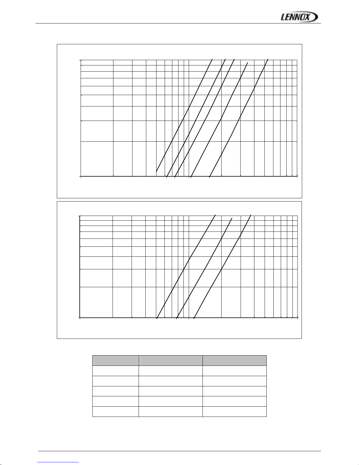
WATER CONDENSING
FLEXYII_WSHP-IOM-0909-E Page 21
Pressure Loss - Heat plate Exchanger
A
B
CD
E
10
100
1 10 100
Water flow (m3/h)
Pressure Loss (kPa)
Pressure Loss - WATER FILTER
A
B
C
1.0
10.0
1 10 100
Water flow (m3/h)
Pressure Loss (kPa)
FWH/FWM
Exchanger Curve Filter Curve
85 C B
100 D B
120 D B
150 E C
170 E C
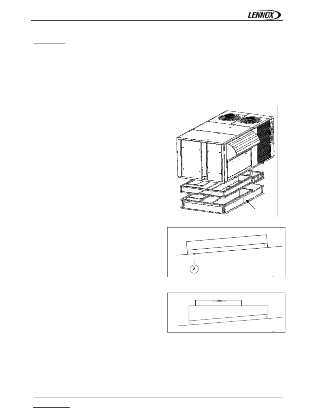
INSTALLATION ON A ROOFMOUNTING FRAME
FLEXYII_WSHP-IOM-0909-E Page 22
CAUTION:
- An approach ramp must be installed if the unit’s installation requirements tell that it's
necessary to reach the main switch. This recommendation is valid for installations in
general and in particular for return and curbs. It’s also valid to reach other parts of the
unit: filters, refrigerant circuit, etc…
- It’s advised to fix curbs and roofcurbs to the unit.
As levels are adjustable, observe the following
recommendations when installing the equipment
Above all, ensure that all the adjustable returns are facing
outward (“1” figure 4). They are usually turned inside-out
for transport.
Place the roof mounting frame on the trimmer beam by first
lining up the inlet and the outlet opening. (“2”- figure 5)
After levelling the frame, secure the adjustable returns on
the trimmer.
It is important to centre the unit on the roof frame
c
Fig. 4
Fig. 5
Fig. 6
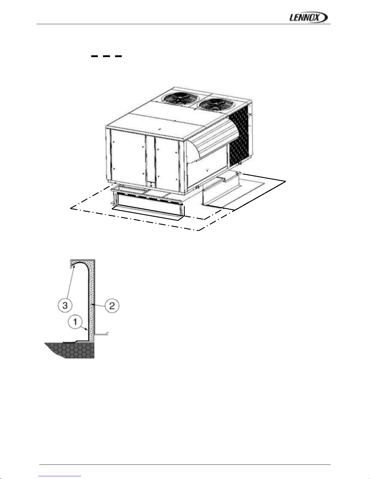
INSTALLATION ON A ROOFMOUNTING FRAME
FLEXYII_WSHP-IOM-0909-E Page 23
When the frame is correctly positioned, it is essential to secure the assembly with a disconnected stitched welded seam (20 to
30mm every 200mm
) along the outside or by using an alternative method
CURBING AND FLASHING
Outside of frame must be insulated with rigid type insulation;
We recommend a minimum of 20 mm thick insulation (2 - figure 7).
Check that the insulation is continuous, counter flash and seal around the frame
as shown in (1-figure 7).
CAUTION: To be effective, the upstream must end below the drop edge (3 - figure
7).
Where pipes and electrical conduits extend through the roof, flashing must
conform to local codes of practice
Before installing the equipment, make sure that seals are not damaged and check that the unit is secured to the mounting
frame. Once in position, the bottom of the equipment must be horizontal.
The installer must comply with local authority standards and specifications.
Fig. 7
INSTALLATION ON A ROOF MOUNTING FRAME
FLEXYII_WSHP-IOM-0909-E Page 24
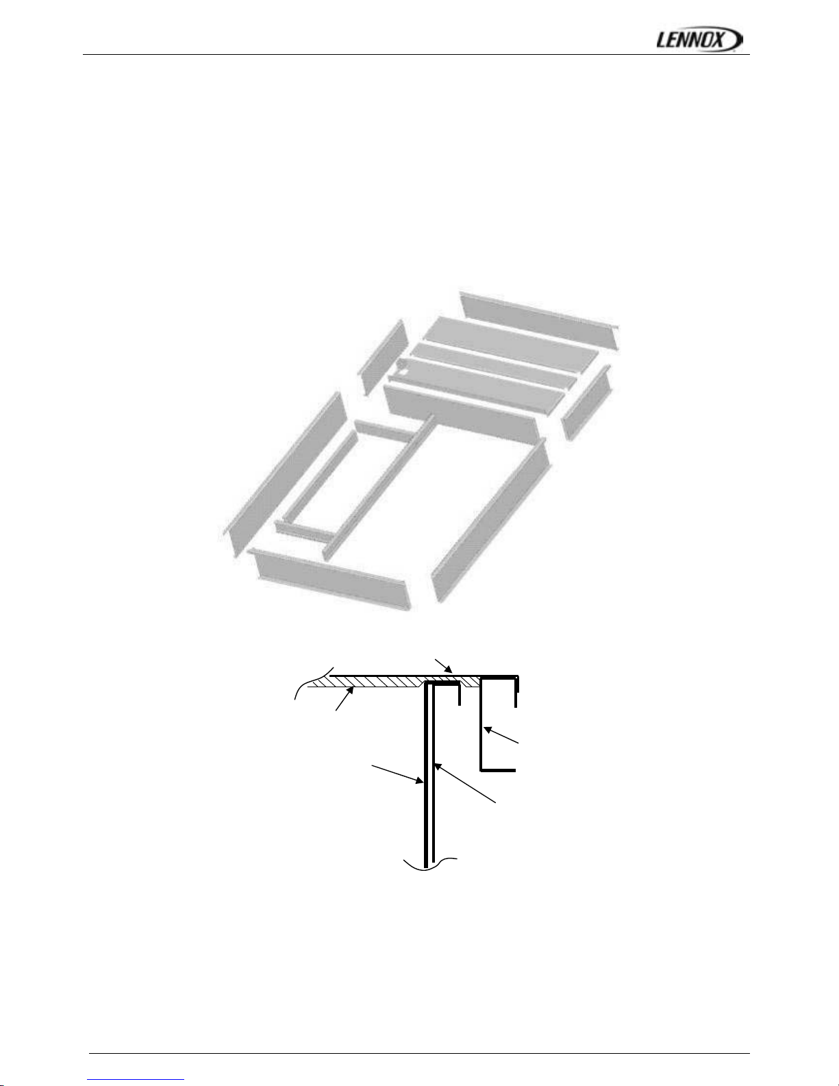
NON ADJUSTABLE NON ASSEMBLIED ROOFCURB INSTALLATION
FRAME PARTS IDENTIFICATION
Figure 8 shows the different parts used in the assembly of this roof mounting frame.
INSTALLATION
The roof mounting frame provides support when the units are installed in down-flow configurations.
The non adjustable, non assembled roof mounting frame can be installed directly on decks having adequate structural strength
or on roof supports under deck.
NOTE: frame assembly must be installed flat, leveled within 5mm per linear meter in any direction
UNIT FLOOR
UNIT FLOOR
A
IR DUCT
UNIT Support rail
ROOFCURB
Fig. 8
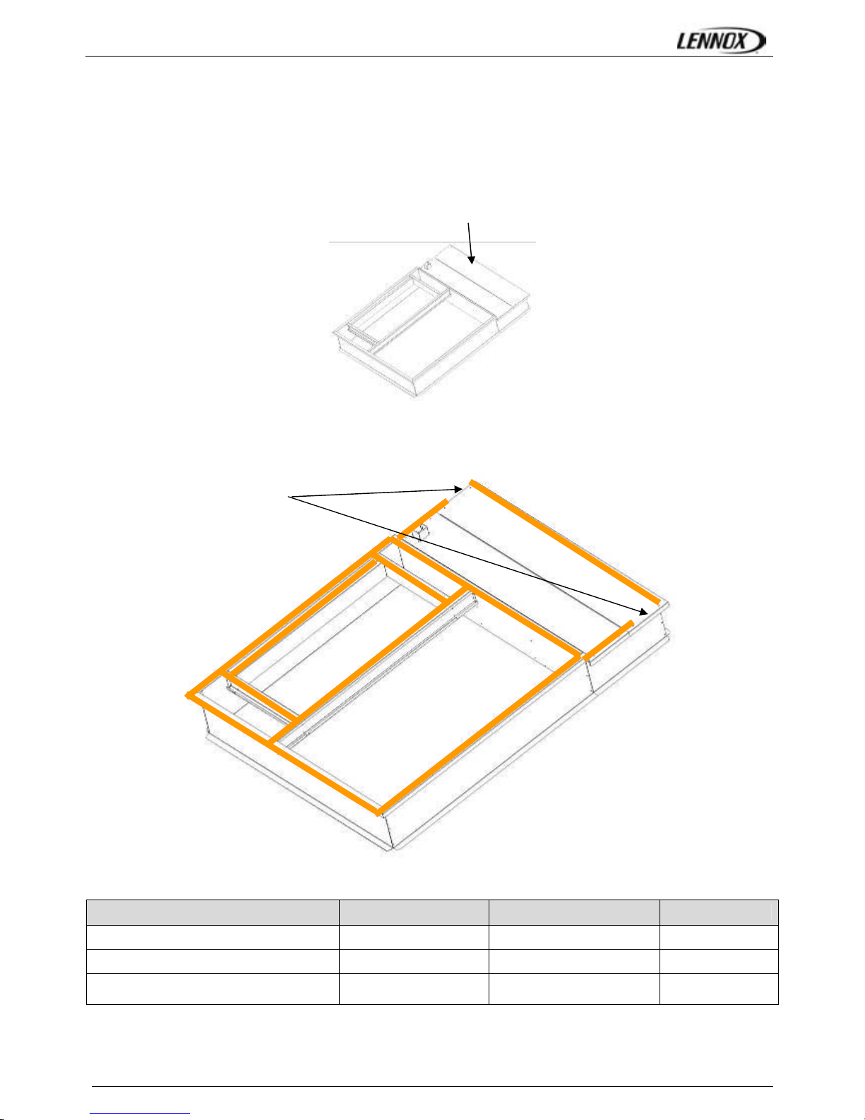
NON ADJUSTABLE ROOFCURB – Installation instructions
FLEXYII_WSHP-IOM-0909-E Page 25
This roof curb will arrive as a packaged on a pallet and need to be built together.
The part will be connected by special corrosion free nails. It is not possible to connect with standard nail equipment because
there is a lot of power needed. Therefore, you need a pneumatic or electric device.
All parts must be sealed with polyurethan sealant during assembly.
Foam Insulation Installing
• Stick large foam pieces underneath the flat top
Foam Gasket Installing
• Stick gasket all around the curb flange’s top
Spare parts
Fbox Gbox Hbox
GASKET 5840071R Grey foam M1 17 m / 0.85 m² 19 m / 0.95 m² 21 m /1.1 m²
INSULATION 5840071R 760 x 1960 - 1.39 m² 920 x 1960 - 1.79m² tbd
Rivets 5820542X 4.8 x 8 mm 100 130 160
Let it free on 200 mm
long to enable water
drainage
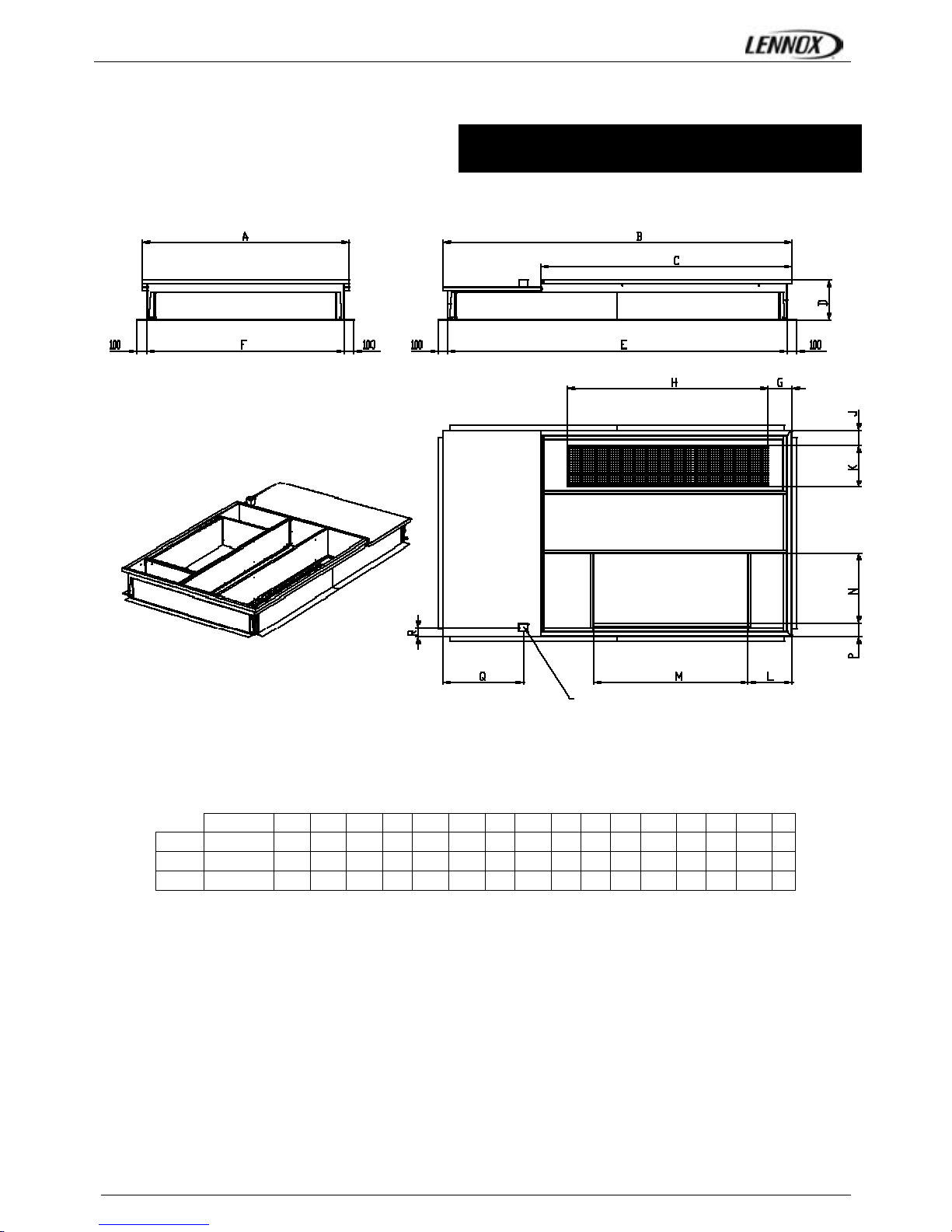
ADJUSTABLE ROOFCURB
FLEXYII_WSHP-IOM-0909-E Page 26
SIZE A B C D E F G H J K L M N P Q R
F-BOX 85-100-120 2056 2770 2005 400 2672 1959 130 1747 145 420 336 1432 700 140 620 95
G-BOX 150-170 2056 3466 2493 400 3367 1959 234 1997 145 420 430 1540 700 140 800 95
H-BOX 200-230 2056 4100 2493 400 4003 1959 234 1997 145 420 430 1830 800 80 1133 95
All units
RETURN AIR
SUPPLY AIR
MAIN POWER ENTRY
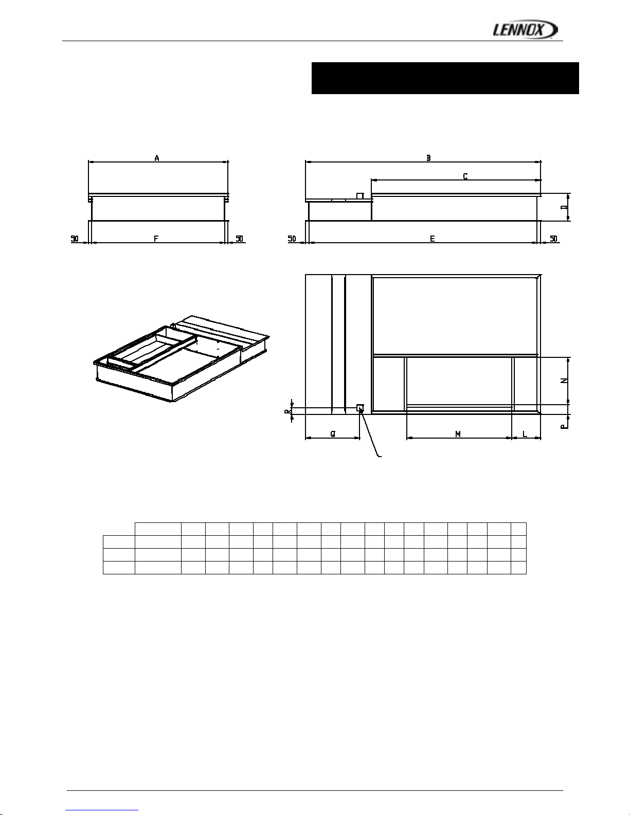
NON ADJUSTABLE NON ASSEMBLED ROOFCURB
FLEXYII_WSHP-IOM-0909-E Page 27
SIZE A B C D E F G H J K L M N P Q R
F-BOX 85-100-120 2056 2770 2005 400 2672 1959 130 1747 145 420 336 1432 700 140 620 95
G-BOX 150-170 2056 3466 2493 400 3367 1959 234 1997 145 420 430 1540 700 140 800 95
H-BOX 200-230 2056 4100 2493 400 4003 1959 234 1997 145 420 430 1830 800 80 1133 95
SUPPLY AIR
MAIN POWER ENTRY
All units
MULTIDIRECTIONAL ROOFCURB
FLEXYII_WSHP-IOM-0909-E Page 28
SIZE A B C D E F G H J K L M N P Q R S
F-BOX 85-100-120 2056 2745 2005 800 100 600 300 1335 88 980 780 600 100 600 100 600 100
G-BOX 150-170 2056 3441 2493 800 100 600 300 1540 88 980 780 900 100 600 100 900 100
H-BOX 200-230 2056 4063 2493 800 100 600 300 1830 88 980 780 1000 100 600 100 1000 100
SUPPLY AIR RETURN AIR
RETURN AIR
SUPPLY AIR
All units

RETURN ROOFCURB
FLEXYII_WSHP-IOM-0909-E Page 29
SIZE A B C D E F G H J K L M N P Q R
F-BOX 85-100-120 2156 2740 2005 1030 2056 2005 1650 180 310 840 140 700 1440 326 593 95
G-BOX 150-170 2156 3437 2494 1030 2056 2494 1650 410 310 840 140 700 1540 434 770 95
H-BOX 200-230 2156 4073 2494 1030 2056 3294 2550 100 310 840 80 800 1830 434 1113 95
CAUTION: An approach ramp must be installed if the
machine installation requirements tell that it's necessary
to reach the main switch. This recommendation is valid
for installations in general and in particular for return
and curbs. It’s also valid to reach other parts of the unit:
filters, refrigerant circuit, etc…
SUPPLY AIR
EXHAUST AIR
All units
RETURN AIR
MAIN POWER ENTRY

RETURN HORIZONTAL ROOFCURB
FLEXYII_WSHP-IOM-0909-E Page 30
SIZE A B C D E F G H J K L M N P
F-BOX 85-100-120 2056 2755 2005 1220 1180 100 400 100 1335 200 1605 200 100 700
G-BOX 150-170 2056 3465 2493 1220 1180 100 400 100 1540 200 2000 200 100 700
H-BOX 200-230 2056 4095 2493 1305 1205 200 400 150 1830 150 2293 100 260 700
CAUTION: An approach ramp must be installed if the
machine installation requirements tell that it's necessary to
reach the main switch. This recommendation is valid for
installations in general and in particular for return and
curbs. It’s also valid to reach other parts of the unit: filters,
refrigerant circuit, etc…
EXHAUST AIR
All units
RETURN AIR
SUPPLY AIR MAIN POWER ENTRY

TRANSITION CURB
FLEXYII_WSHP-IOM-0909-E Page 31
SIZE A B C D E F G H J K L M N
F-BOX 85-100-120 2056 2008 2072 366 2783 1880 70 85 530 700 145 1432 342
G-BOX 150-170 2056 2496 2072 366 3480 2377 70 85 530 700 145 1540 440
H-BOX 200-230 2056 2493 2072 366 4106 2377 70 85 530 800 85 1830 440
SUPPLY AIR
MAIN POWER ENTRY
RETURN AIR
All units

ENERGY RECOVERY
FLEXYII_WSHP-IOM-0909-E Page 32
SIZE A B C D E F
F-BOX 85-100-120 2279 2212 1447 360 1911 938
G-BOX 150-170 2539 2473 1544 457 2211 938
H-BOX 200-230 2789 2723 1703 616 2461 938
All units
A
C
B
E
F
D

ENERGY RECOVERY INSTALLATION
FLEXYII_WSHP-IOM-0909-E Page 33
1) The unit being already erected on the roofcurb, remove the lifting lug shown on [A], and the doors of the Recovery
module
[B].
2) Fit the support part of the Recovery Module on interior level of the rooftop ,
3) Fix the Recovery Module at the roof of the rooftop
and corner structures by using self-driling screws.
4) Apply Mastic on side junctions and on higher junction.
Pictures taken during assembling test of Recovery Module (H Size)
Fig. 25
zoom
1
2
3
zoom
zoom
1
2
3

ENERGY RECOVERY INSTALLATION
FLEXYII_WSHP-IOM-0909-E Page 34
STEP 1: Rooftop configuration
This picture shows how the rooftop configuration has to be before recovery module assembling
No Hood
No panel
The lifting lug and the corner sheet metal
have to be removed.
The head guard on the left corner of the
rooftop has to be flattened.

ENERGY RECOVERY INSTALLATION
FLEXYII_WSHP-IOM-0909-E Page 35
STEP 2: Lifting
For Recovery module lift, use lifting lugs localised at the top of each corner structures

ENERGY RECOVERY INSTALLATION
FLEXYII_WSHP-IOM-0909-E Page 36
During installation phase, fit the support part on the interior level of the rooftop
STEP 3: Fitting
SUPPORT PART
INTERIOR LEVEL

ENERGY RECOVERY INSTALLATION
FLEXYII_WSHP-IOM-0909-E Page 37
STEP 4: Check
In the same way, roof of the recovery module and the rooftop has to be at the same level
SAME LEVEL
MODULE ROOFTOP
A good fit can be controled by looking at the junction between the rooftop and the recovery module:
The junction has to be at the same level.
SAME LEVEL
70 mm
Size 150 & 170
For 150 and 170 sizes, a deviation of 70mm
exists between rooftop and recovery module
(see picture on the right).

ENERGY RECOVERY INSTALLATION
FLEXYII_WSHP-IOM-0909-E Page 38
STEP 5 : Fixing
And fix the top of the module to the rooftop by using self-driling screws 19mm
Self-drilling screws 19mm D6.3
When the module is well fitted, fix the corner structures to the rooftop by using self-
drilling screws 32mm
Self-drilling screws 32mm D4.8

ENERGY RECOVERY INSTALLATION
FLEXYII_WSHP-IOM-0909-E Page 39
Apply mastic on side junctions and higher junction
STEP 6: Masticate

ENERGY RECOVERY INSTALLATION
FLEXYII_WSHP-IOM-0909-E Page 40
The Recovery module is sent with a power cable and a T-lan cable
STEP 7: Electrical wiring
Power cable
T-lan cable
These 2 cables have to be inserted through this hole

ENERGY RECOVERY INSTALLATION
FLEXYII_WSHP-IOM-0909-E Page 41
Then fix the 2 cables on the grid of the extraction roofcurb and insert them in rooftop electrical panel as shown
Cables from the module, through the
hole, to rooftop electrical panel

ENERGY RECOVERY INSTALLATION
FLEXYII_WSHP-IOM-0909-E Page 42
To check the wiring, please refer to Rooftop and Recovery Module electrical diagram.
Then connect the power cable from the module to the rooftop, and the t-lan to the
Climatic50 (or the BE50 if presents in electrical rooftop panel)
Recovery Module Connection
Exctraction Roofcurb Connection
Be careful: Check connections and connect male connections to good
female one.
Roofcurb and recovery module connectors are the same.
Actuator Roofcurb Connection

ENERGY RECOVERY INSTALLATION
FLEXYII_WSHP-IOM-0909-E Page 43
STEP 8: Roof curb economiser Adjustment
With Heat Recovery module option the extract air goes through the wheel, that’s why the
economiser of the roofcurb has to be permanently fully closed.
If roofcurb economiser is not fully closed, close it manually
And don’t connect the actuator to the rooftop.
Actuator Roofcurb
not connected

ECONOMISER AND EXTRACTION
FLEXYII_WSHP-IOM-0909-E Page 44
ECONOMISER
Free cooling can be provided through the use of fresh air which is more appropriate
than excessive cooling amounts of return air.
The economiser is factory fitted and tested prior to shipment.
It includes two dampers operating from a 24V actuator
RAIN HOOD
It also includes a factory fitted rain hood. Hoods is folded during transportation to limit
risks of damage and must be unfolded on site as shown on fig. 9
EXTRACTION
Installed with economiser assembly, the gravity exhaust dampers relieve the pressure
when outside air is introduced into the system.
When large amount of fresh air is introduced into the system power exhaust fans can be used to equalise the pressures.
The extraction fan runs when return air dampers are being closed and supply air blower is in operation. The extraction fan runs
when outdoor air dampers are at least 50% open (adjustable value). It is overload protected.
NOTE: When horizontal flow configuration is required, the multidirectional roof curb will be installed.
0-25% FRESH AIR MANUAL
It is enough to loosen the mobile grid's screws and to make it slip.
0%: screw into limit stop on the right
25%: screw into limit stop on the left
FRESH AIR
R
ETURN AIR
E
XHAUST AIR
SUPPLY AIR
Fig. 9
FLEXY II PRINCIPLE SKETCH
MULTIDIRECTIONAL ROOFCURB
PRINCIPLE SKETCH
ENERGY RECOVERY MODULE PRINCIPLE SKETCH RETURN ROOFCURB PRINCIPLE SKETCH

COMMISSIONING
FLEXYII_WSHP-IOM-0909-E Page 45
THIS WORK MUST ONLY BE CARRIED OUT BY TRAINED REFRIGERATION ENGINEERS
FILL THE COMMISSIONNING SHEET AS YOU GO ALONG
Don’t forget to open the isolation Valves on the liquid line before starting the unit (see sticker below)
ELECTRICAL CONNECTIONS
- Ensure that the power supply between the building and the unit meets local authority standards and that the cable specification
satisfies the start-up and operating conditions.
ENSURE THAT THE POWER SUPPLY INCLUDES 3 PHASES
- Check the following wire connections for tightness: Main switch connections, mains wires linked to the contactors and
circuit breakers and the cables in the 24V control supply circuit.
PRELIMINARY CHECKS
- Ensure that all drive motors are secure.
- Ensure that the adjustable pulley blocks are secure and that the belt is tensioned with the transmission correctly aligned.
Refer to the next section foe details.
- Using the electrical wiring diagram, check the conformity of the electrical safety devices (circuit breaker settings, presence
and rating of fuses).
- Check the temperature probe connections.
ISOLATION VALVES MUST BE
OPENED BEFORE RUNNING
G1 G2

COMMISSIONING
FLEXYII_WSHP-IOM-0909-E Page 46
STARTING THE UNIT
At this point the unit circuit breakers should be open
You will need a DS50 maintenance controller or Adalink with
appropriate Interface.
The jumpers are factory set and the configuration switches
are adjusted depending on the option the type of unit.
Connecting the CLIMATIC displays
Close the 24V Control Circuit breakers.
The CLIMATIC 50 starts after 30s
Reset the DAD photo (If fitted)
Check and adjust the control settings.
Refer to the control section in this manual to adjust the
different parameters.
POWERING THE UNIT
- Power up the unit by closing the isolator switch (if fitted). At this point the blower should start unless the climatic does
not energise the contactor. In this particular case the blower
can be forced by bridging the port NO7 and C7 on
connector J14 on the Climatic. Once the fan is running,
check the rotation direction. Refer to the rotation arrow
located on the fan.
- The fans and compressors direction of rotation is checked
during the end of line test. They should therefore all turn in
either the right or wrong direction.
NOTE: A compressor rotating in the wrong direction will fail.
- If the fan turns in the wrong direction (the right direction is
shown on figure n° 11), disconnect the main power supply
to the machine at the building's mains switch, reverse two
phases and repeat the above procedure.
- Close all circuit breakers and power up the unit, remove
the bridge on connector J14 if fitted.
- If now only one of the components rotates in the wrong
direction, disconnect the power supply at the machine's
isolator switch (if fitted) and reverse two of the component’s
phases on the terminal within the electrical panel.
- Check the current drawn against the rated values, in
particular on the supply fan (ref. page 33).
- If the readings on the fan are outside the specified limits,
this usually indicates excessive air flow which will affect the
life expectancy and the thermodynamic performances of the
unit. This will also increase the risks of water ingress into
the unit. Refer to the "Air Flow Balancing" section to correct
the problem.
At this point attach the manometers to the refrigerant circuit
Fig. 11

COMMISSIONING
FLEXYII_WSHP-IOM-0909-E Page 47
RUN TEST
Start unit in cooling mode
Thermodynamic readings using manometers and prevailing
environmental conditions
No rated values are given here. These depend on the climatic
conditions both outside and inside the building during
operation. However, an experienced refrigeration engineer
will be able to detect any abnormal machine operation.
Safety test
- Check Air pressure switch (if fitted) "Dirty filter" detection
test: vary the set-point value (menu page 3413 on DS50) in
respect to the air pressure value. Observe the response of
the CLIMATIC™.
- Same procedure for detecting "Missing Filter" (page menu
3412) or "Air Flow Detection" (page menu 3411).
- Check the smoke detection function (if fitted).
- Check the Firestart by pressing the test button (if fitted).
- Disconnect the circuit breakers of the capacitor fans and
check the high pressure cut-out points on different refrigerant
circuits.
Reverse cycle test
This test is designed to check the good operation of the 4way reversing valves on heat pump reversible systems. Start
the reverse cycle by adjusting the cold or hot temperature
threshold data according to the indoor and outdoor conditions
at the time of test (menu 3320).

VENTILATION : BELT TENSION
FLEXYII_WSHP-IOM-0909-E Page 48
BELT TENSION
On delivery, the drive belts are new and correctly tensioned.
After the first 50 operating hours check and adjust the
tension. 80% of the total elongation of belts is generally
produced during the first 15 hours of operation.
Before adjusting the tension, make sure that the pulleys are
correctly aligned.
To tension the belt, set the height of motor support plate by
moving the plate adjustment screws.
The recommended deflection is 20 mm per meter from centre
to centre.
Check that according to the diagram below (figure 12), the
following ratio remains the same.
The belts should always be replaced when:
- The disk is set to maximum,
- The belt rubber is worn or the wire is visible.
Replacement belts must have the same rated size as the
ones they are replacing. If a transmission system has several
belts, they must all be from the same
NOTE:
An under-tensioned belt will slip, heat and wear prematurely.
On the other hand, if a belt is over-tensioned, the pressure on
the bearings will cause them to over-heat and wear
prematurely. Incorrect alignment will also cause the belts to
wear prematurely.
Fig. 12

VENTILATION : PULLEYS
FLEXYII_WSHP-IOM-0909-E Page 49
MOUNTING AND ADJUSTING PULLEYS
F
AN PULLEY REMOVAL
Remove the 2 screws and put one of them in the extraction
threaded screw.
Screw in fully. The hub and the pulley will separate from each
other.
Remove the hub and the pulley by hand without damaging
the machine.
F
AN PULLEY INSTALLATION
Clean and de-grease the shaft, hub and conical bore of the
pulley. Lubricate the screws and install the hub and pulley.
Position the screws without turning them.
Place the assembly on the shaft and screw in the screws
alternatively and evenly. Using a mallet or a hammer with a
wooden wedge, tap on the face of the hub to keep the
assembly in place. Torque the screws to 30 Nm.
Take the pulley in both hands and shake it vigorously to make
sure everything is in place.
Fill the holes with grease for protection.
NOTE: During installation, the key should never protrude out
of its groove.
After 50 operating hours, check that the screws are still in
place.
M
OTOR PULLEY INSTALLATION & REMOVAL
The pulley is held in position by the key and a screw located
in the groove. After unlocking, removing this screw by pulling
against the shaft spindle (if necessary, use a mallet and tap
uniformly on the hub to remove it).
To assemble, proceed in the reverse order after having
cleaned and de-greased the motor shaft and the pulley bore.
P
ULLEYS ALIGNMENT
After adjusting one or both of the pulleys, check the
transmission alignment using a ruler placed on the inner face
of the two pulleys.
NOTE: The warranty may be affected if any major
modification is made to the transmission without obtaining our
agreement beforehand.

VENTILATION : AIRFLOW BALANCING
FLEXYII_WSHP-IOM-0909-E Page 50
The actual resistance of ductwork systems is not always identical to the calculated theoretical values. To rectify this, it may be
necessary to modify the pulley and belt setting. To this effect, the motors are fitted with variable pulleys.
SITE TEST AND MAINTENANCE
Measure the motor absorbed power.
If the absorbed power is greater and the pressure lower than the rated values, the ventilation system has a lower pressure drop
than anticipated. Reduce the flow by reducing the rpm. If the system resistance is significantly lower than design, there is a risk
that the motor will overheat resulting in an emergency cut out.
If the absorbed power is lower and the pressure greater than the rated values, your system has a higher pressure drop than
anticipated. Increase the flow by increasing the rpm. At the same time you will increase the absorbed power which may result in
having to increase the motor size.
To carry out the adjustment and to avoid a time-consuming re-start, stop the machine and if necessary lock the main switch.
First unscrew the 4 Allen screw(s) on the pulley (see figure 13).
Actual diameter (DM) or distance between faces for a given number of
turns from fully closed with SPA belt in (mm)
Pulley
type
Pulley
External
Diameter
Min
Dia /
Min
Dist
Max
Dia /
Max
Dist
Nb of turns
from fully
closed to
fully open
0.5 1 1.5 2 2.5 3 3.5 4 4.5 5 5.5
95 116 5 114 112 110 108 106 103 101.3 99.2 97.1 95 -
8450 /
D8450
120
20.2 28 5 21 21.8 22.5 23.3 24.1 24.9 25.7 26.4 27.2 28 -
110 131 5 129 127 125 123 121 118 116 114 112 110 -
8550 /
D8550
136
20.6 31.2 5 21.6 22.7 23.8 24.8 25.9 26.9 28 29.1 30.1 31 -
Table_1
The easiest way to determine the fan rotation speed is to
use a Tachometer. If not available the fan rpm can be
estimated using the following two methods.
1
st
Method with the pulley secured in place:
Measure the distance between the two outside faces of the
pulley.
Using table (1) the motor pulley actual diameter can be
estimated.
L
Fig. 13

VENTILATION : AIRFLOW BALANCING
FLEXYII_WSHP-IOM-0909-E Page 51
2nd method when adjusting the pulley :
-Close the pulley fully and count the number of turns
from fully closed position. Using table_1 determine the
motor pulley actual diameter.
-Record the fix fan pulley diameter.(DF)
-Determine the fan speed using the following formulae:
FMMOTORFAN
/DDrpmrpm ×=
Where: rpm
MOTOR
:from the motor plate or table_2
D
M
: from table_1
D
F
: from machine
Once the pulleys are adjusted and the belt checked and
tensioned, start the fan motor and record the Amps and
Voltage between the phases:
Using the measured data and table_2
-Theoretical mechanical power at the fan shaft:
P
meca fan
= P
meca Motor
x η
Transmission
P
meca fan
= P
elec
x η
meca motor
x η
Transmission
P
meca fan
= V x I x √3 x cosϕ x η
meca motor
x η
Transmission
This formula can be approximated in this way
P
meca fan
= V x I x 1.73 x 0.85 x 0.76 x 0.9
With the fan “rpm” and the mechanical power at the fan
shaft an operating point and the supplied airflow can be
estimated using the fan curves.
CHECKING AIRFLOW AND ESP
Using the fan curves on page 36 to 40, the airflow, the total
pressure available (P
TOT
) and the corresponding dynamic
pressure (Pd) can now be estimated, for a specific
operating point;
The next step consists in estimating the pressure losses
across the unit.
This can be achieved using the “dirty filter pressure sensor”
and the accessories pressure drop table: table_3
Also the pressure drop due to the duct inlet into the roof-top
unit can be taken as 20 to 30 Pa.
∆P
INT
= ∆P
filter + coil
+ ∆P
Inlet
+ ∆P
Options
Using the results from above, the external static pressure
(ESP) can then be estimated:
ESP = P
TOT
- Pd - ∆P
INT
Table_ 2 Motor information
Motor Size Nom. Speed
Cos ϕ η
meca motor
0.75 kW 1400 rpm 0.77 0.70
1.1kW 1429 rpm 0.84 0.77
1.5kW 1428 rpm 0.82 0.79
2.2kW 1436 rpm 0.81 0.81
3.0kW 1437 rpm 0.81 0.83
4kW 1438 rpm 0.83 0.84
5.5kW 1447 rpm 0.85 0.86
7.5kW 1451 rpm 0.82 0.87
9.0kW 1455 rpm 0.82 0.88
11.0kW 1451 rpm 0.85 0.88
Table_3 Accessories pressure drops
Economiser
G4
Filters
F7
Filters
UV
LIGH
T
Hot
Water
coil S
Hot
Water
coil H
Electric
Heater
S
Electric
Heater
M
Electric
Heater
H
Heating
Gaz
fired H
Adjustable
roofcurb
Multidire
ctional
Roofcurb
Heat
Recovery
Modul
Fresh Air
12000 12 1 75 18 9 15 3 5 6 14 17 22 164
15000 19 7 105 30 13 22 6 7 7 23 27 33 204
85
23000 45 28 199 63 26 44 7 9 11 53 63 73 313
14000 17 5 94 26 11 19 6 7 8 20 23 30 191
18500 29 15 143 44 18 31 8 10 11 34 41 51 252
100
23000 45 28 199 63 26 44 11 14 16 53 63 78 313
15000 19 7 105 30 13 22 7 8 9 23 27 35 204
20500 36 21 167 52 21 37 10 12 13 42 50 62 279
120
23000 45 28 199 63 26 44 12 15 17 53 63 78 313
18000 6 1 75 15 6 10 4 5 7 16 30 35 170
150
26000 12 12 130 33 12 19 9 10 13 33 62 72 245
35000 22 29 204 54 19 33 15 18 23 59 112 131 329
21000 8 5 94 21 8 14 8 9 10 21 40 49 198
30000 16 19 161 42 15 25 10 13 15 44 82 95 282
170
35000 22 29 204 54 19 33 17 19 21 59 112 131 329
24000 12 3 88 18 7 11 16 15 14 21 53 67 173
35000 26 18 154 39 13 22 22 21 20 44 112 133 252
200
43000 39 31 211 54 19 31 24 26 29 66 169 195 310
27000 15 7 105 24 8 14 18 18 17 26 67 84 195
39000 32 24 182 46 16 26 24 24 25 55 139 163 281
230
43000 39 31 211 54 19 31 24 26 29 66 169 195 310

VENTILATION : AIRFLOW BALANCING
FLEXYII_WSHP-IOM-0909-E Page 52
EXAMPLE
The unit used for this example is a FGM170ND with standard supply and return airflow configuration. It is also fitted with an
economiser and an electric heater type H.
It is fitted with 2 ADH450 L fans which curve is shown on page 36 and 2x 5.5 kW motors..
- Motor rpm: 1447 rpm
- cosϕ = 0.83
- Voltage = 400V
- Current = 9.00A (per fan)
P
mech fan
= V x I x √3 x cosϕ x η
mech motor
x η
Transmission
= 400 x 9.00 x √3 x 0.83 x 0.86 x 0.9 = 4.00kW
The unit is also fitted with 2 transmission kits 3.
- Fixed Fan pulley: 200mm
- Motor adjustable pulley type “8550” opened 4 turns from fully closed or measured distance between pulley end plates is
29.1mm: from table_1 it can be determined that each motor pulley has a diameter of 114.2mm
rpm
FAN
= rpm
MOTOR
x DM / DF = 1447 x 114.2 / 200 = 826 rpm
Using the fan curve, the operating point can
be located.
In order to facilitate the calculation, you
won’t make any mistake by considering
that the external static pressure available is
the one calculated with one fan providing
the half of the nominal flow (here
15000m3/h).
It can be determined that the fan is providing
approximately 15000 m3/h
with a total
pressure P
TOT
= 630 Pa
The pressure losses in the unit are the sum of
all pressure drops across the different parts of
a unit:
- Coil and filter (measured) = 89 Pa
- Inlet into the unit = 50 Pa
- Options = 16 Pa for economiser and 15
Pa for electric heater H
∆P = 89 + 16 + 15 +50 = 170 Pa
The dynamic pressure at 15000m
3
/h is given
at the bottom of the fan curve.
Pd = 81 Pa
The external static pressure available is
therefore
ESP = P
TOT
- Pd - ∆P
INT
=630 - 91 - 170 = 369
Pa
826rpm
630Pa

VENTILATION : AIRFLOW BALANCING
FLEXYII_WSHP-IOM-0909-E Page 53
AT15-15G2L(*)
(*) The performances of twin fan units can be calculated starting from the corresponding operation point for a single fan
(see the figure behind) by applying the formulas below.
- pressure : PTwin = P x 1
- volume flow rate : Qb = Q x 2
- impeller power: Wb = W x 2,15
- fan speed : Nb = N x 1,05
- Lws : Lwsb = Lws + 3 dB

VENTILATION : AIRFLOW BALANCING
FLEXYII_WSHP-IOM-0909-E Page 54
AT18-18S

VENTILATION : AIRFLOW BALANCING
FLEXYII_WSHP-IOM-0909-E Page 55
ADH355L

VENTILATION : AIRFLOW BALANCING
FLEXYII_WSHP-IOM-0909-E Page 56
ADH450L

VENTILATION : AIRFLOW BALANCING
FLEXYII_WSHP-IOM-0909-E Page 57
ADH500L

FILTERS
FLEXYII_WSHP-IOM-0909-E Page 58
F
ILTER REPLACEMENT
After opening the filter access panel, lift the filter retaining log.
The filters can then be removed and replaced easily by sliding the dirty filters out and clean ones in.
The CLIMATIC controller can monitor the pressure drop across the filter (If option fitted)
The following set points can be adjusted depeding on the installation.
“Airflow” in page 3411 = 25Pa by default
“No filter “ in page 3412 = 50Pa by default
“Dirty Filter” in page 3413 = 250Pa by default
The actual pressure drop measured accross the coil can be read on the Climatic Display DS50 in menu 2131
.
The following faults may be identified
-Fault code 0001 AIRFLOW FAILURE, if measured ∆P across the filter and coil is below the value set in page 3411
-Fault code 0004 DIRTY FILTERS, if measured ∆P across the filter and coil is above the value set in page 3413
-Fault code 0005 MISSING FILTERS, if measured ∆P across the filter and coil is below the value set in page 3412
Be Careful: do the filters' fire classification's choice according to
the local regulations

VENTILATION : AIR SOCK CONTROL
FLEXYII_WSHP-IOM-0909-E Page 59
AIR SOCK CONTROL
FANSTART OPERATION
The use of air socks for space conditioning allows high air volumes to be distributed at low velocity and is becoming a common
feature in many applications. To accommodate this trend, Air-sock control is offered which allows the air socks to be
progressively filled with air on start up. It takes up to 1 minute to go from 0% of air to full air flow.
START-UP
This option requires the economiser to be delivered inside the machine
Both return air and fresh air damper are linked with and independent actuator.
The return air damper is controlled by a spring return damper driven by the opposite signal delivered to the fresh air damper.
An auxiliary switch allows setting a minimum (few %) of return air opening
before the fan is switched on.
Starting steps:
- Both dampers are fully closed and Fan is OFF
- Rooftop is set to RUN (by the schedule or the remote display order)
- Return air damper move to the minimum position manually adjustable
on the auxiliary switch, Fresh air damper is OFF
- Fan motor starts
- Return air damper goes to 100% return air slowly during 1 minute
allowing the duct to be smoothly inflated
- Finally, the fresh air damper and return air damper return to adjusted
fresh air ratio recorded in the climatic50 program
The return air damper with its auxiliary switch

VENTILATION : UV lights
FLEXYII_WSHP-IOM-0909-E Page 60
UV LIGHT
UV light option allows to kill bacteria living on the fin.
The UV lamp emits shortwave UV-C ultraviolet radiation which is harmful to skin and eyes
It can cause serious skin burns and eye inflammation within ONE SECOND of exposure
Do not enter the machine while UV are switched on
Make sure the UV light circuit breaker is OFF when opening the return air section door and the
supply air section doors
The following logo will appear to inform about the UV-C radiation risk
A safety interlock is fitted to switch off the access doors to the lamps
Fig. 14
Filters
UV light
COIL
Sight Glass
Door opened
Safety locks

HEATING : HOT WATER COIL
FLEXYII_WSHP-IOM-0909-E Page 61
HYDRAULIC CONNECTIONS
Hot water coils offer fully modulating control through the
use of a 3 way valve. The hot water coil, connections and
valves are all tested at pressure of 15 bars. Frost protection
is provided by forcing the opening the 3 way valve when
supply temperature from hot water coil falls below 8°C and
by stopping the outdoor fan when that supply temperature
falls below 6°C. In addition to that, the 3 ways is also
opened at 10% value if the outdoor temperature falls below
an adjustable value.
Hot water coils are always factory fitted, wired and fully
tested, prior to shipment.
Hot water coil includes automatic purge system.
The hot water coil is fitted with a three way proportional
valve and two isolating shut off valves. Two spanners must
be used to tighten the connections. One spanner must
maintain the valve body when connecting the pipe-work to
the main. Failure to do so may damage the pipes joints and
invalidates the warranty.
Filling up and starting the system
- Adjust the control for Heating by reducing the
simulated ambient temperature down to 10°C
- Check that the red indicators located under the valve
actuator are moving correctly with the signal.
- Fill the hydraulic system and bleed the coil using the
air vents. Check incoming hot water.
- Check the various connections for possible leaks
FREEZE PROTECTION
1) Glycol for freeze protection.
Check the hydraulic system contains Glycol for protection
against freezing.
GLYCOL IS THE ONLY EFFECTIVE PROTECTION
AGAINST FREEZING
The antifreeze must protect the unit and avoid icing under
winter conditions.
WARNING: Mono-ethylene glycol based fluids may
produce corrosive agents when mixed with air.
2) Drain the installation.
You must ensure that the manual or automatic air bleeders
have been installed on all high points in the system. In
order to drain the system, check that all the drain cocks
have been installed on all low points of the system.
HOT WATER COILS FROZEN DUE TO LOW AMBIENT
CONDITIONS ARE NOT COVERED BY THE
WARRANTY.
ELECTROLYTIC CORROSION
Attention is drawn to the corrosion problems resulting from
electrolytic reaction created by unbalanced earth
connections.
ANY COIL DAMMAGED BY ELECTROLYTIC
CORROSION IS NOT COVERED BY THE WARRANTY

HEATING : HOT WATER COIL
FLEXYII_WSHP-IOM-0909-E Page 62
Hot water coil connection
F-G-H box
Pipe Internal Diameters (DN)
M
AXIMUM WORKING PRESSURE: 8 BARS
M
AXIMUM WORKING TEMPERATURE: 110°C
F085 F100 F120 F150 F170 F200 F230
S 25 25 25 32 32 32 32
H 32 32 32 40 40 40 40

HEATING : ELECTRIC HEATER
FLEXYII_WSHP-IOM-0909-E Page 63
G
ENERAL INFORMATIONS
The electric heater comprises of shielded resistance heaters, which are smooth stainless steel tubes 6 W/cm2 capacity.
High temperature limit control offers overload protection and is set to 90°C and located at less than 150mm after electric
heaters. This is provided as a standard feature on the electric heater, with the electric power supply cables made of reticulated
silicon rubber, resistant to temperatures up to 200°C. For any rooftop unit size, three sizes of electric heater are available, S
(standard), M (Medium) and H (high).
FLEXY 2 85, 100 and 120 have:
Standard heat: 30 kW, 2 stages
Medium Heat: 54 kW, Fully modulating (Triac)
High Heat: 72 kW, Fully modulating (Triac)
FLEXY 2 150 and 170 have:
Standard heat: 45 kW, 2 stages
Medium Heat: 72 kW, Fully modulating (Triac)
High Heat: 108 kW, Fully modulating (Triac)
FLEXY 2 150 and 170 have:
Standard heat: 72 kW, 2 stages
Medium Heat: 108 kW, Fully modulating (Triac)
High Heat: 162 kW, Fully modulating (Triac)
Capacity of the medium and high heat heater can be limited electronically to an exact value through the CLIMATIC™ 50.
To reduce installation time and hence cost, electric heaters are always factory fitted, fully wired and tested, prior to shipment.
380V 400V 415V
Module size (kW) Current (A) Cap (kW) Current (A) Cap (kW) Current (A) Cap (kW)
30 40.7 26.8 42.5 29.5 44.5 32.0
45 61.1 40.5 63.8 44.3 66.8 48
54 73.4 48.4 76.6 52.9 80 57.7
72 55.1 36.2 57.5 39.8 60.0 43.1
108 146.8 96.8 153.2 105.8 160 115.4
162 220.2 145.2 229.8 158.7 240 173.1

HEATING : GAS BURNER
FLEXYII_WSHP-IOM-0909-E Page 64
PRELIMINARY CHECKS BEFORE START-UP
NOTE :
ANY WORK ON THE GAS SYSTEM MUST BE CARRIED
OUT BY QUALIFIED PERSONNEL.
THIS UNIT MUST BE INSTALLED IN ACCORDANCE
WITH LOCAL SAFETY CODES AND REGULATIONS AND
CAN ONLY BE USED IN PLANED INSTALLATION
CONDITIONS FOR OUTDOOR.
PLEASE READ CAREFULLY THE MANUFACTURER’S
INSTRUCTIONS BEFORE STARTING A UNIT.
BEFORE COMMISSIONING A UNIT WITH GAS BURNER,
IT IS MANDATORY TO ENSURE THAT THE GAS
DISTRIBUTION SYSTEM (type of gas, available
pressure…) IS COMPATIBLE WITH THE ADJUSTMENT
AND SETTINGS OF THE UNIT.
CHECK ACCESS AND CLEARANCE AROUND THE UNIT
- Make sure one can move freely around the unit.
- A minimum one-meter clearance must be left in front of
the burnt gas exhaust flue.
- Combustion air inlet and burnt gas exhaust(s) must NOT
be obstructed in any way.
S
UPPLY NETWORK PIPE SYZING
MALE THREADED CONNECTION FOR GAZ BURNER: 3/4”
Check that the gas supply line can provide the burners with the
pressure and the gas flow rate necessary to provide the
heating nominal output.
Number of male threaded connections (3/4”)
UNIT SIZE 85 100 120 150 170 200 230
S POWER 1 1 1 2 2 2 2
H POWER 2 2 2 2 2 2 2
GAS FLOW (for G20 at 20mbar and 15°C) m
3
/h
UNIT SIZE 85 100 120 150 170 200 230
S POWER 6.3 6.3 6.3 12.5 12.5 18.8 18.8
H POWER 12.5 12.5 12.5 18.8 18.8 25 25
For modulating gas we have just H power for F, G & H-box
- The gas supply of a Rooftop gas unit must be realized
according to Sound Engineering Practice and the local
safety codes and rules.
- In any case the diameter of pipe-work connected to each
Rooftop must not be smaller than the diameter of the
connection on the Rooftop unit.
- Make sure that a shut-off isolation valve has been
installed before EACH Rooftop.
- Check the supply voltage to the exit of the power supply's
transformer T3 of the burner: it must be between 220 and
240V.
STARTING UP THE GAS BURNER
Purge the pipe-work near the connection on the ignition control
Valve for a few seconds.
- Check that the unit's treatment “Fan” blower is running.
- Set the control to “ON” This will priorities the gas burner.
- Increase the set temperature (room set point temperature) to
a temperature higher than the actual room temperature.
Table4 - Standard start-up Chronology
Time in seconds
Operations
Control operation sequence
Extraction fan
Smoke extraction fan "ON"
30 to 45 seconds pre-ventilation
Fire-up spark electrode 4s
Opening of the gas valve "High Heat"
Flame propagation towards the ionisation
probe
If ionisation within 5s: Normal running
Otherwise fault on gas ingnition control
block
After 5minutes, fault reported on the
climatic controller
If incorrect sequence refer to the fault analysis table to identify the problem
399
400
401
45
46
398
414243
44
373839
40
333435
36
293031
32
9
10
11
567
8
123
4

HEATING : GAS BURNER 60 & 120 kW
FLEXYII_WSHP-IOM-0909-E Page 65
PRESSURE ADJUSTMENTS ON HONEYWELL
PRESSURE REGULATING VALVE TYPE VK 4125 P
Pressure regulator adjustment with 300mbar gas
supply:
- The Burner must run in High Heat mode for this check.
- Place the tube of the “accurate” manometer on the Inlet
pressure port (Figure 15) of the Gas Regulating Valve after
having loosened the screw by one turn
Check and adjust if necessary the valve Inlet pressure to
20.0mbar (G20) or 25.0mbar for Groningen (G25) or
37.0mbar for propane (G31) after gas burner ignition
(fig.16)
High Heat Injection Pressure Checks
Check and adjust if necessary the valve OUTLET pressure
to 10.4mbar (G 20) / 13.1mbar for Groningen (G25) & 34.3
mbar for propane (G31) (fig.17)
The out pressure must be measured on the pressure tap
located on the gas injector support bar to avoid the
pressure drop due to the elbow after the valve
Fig. 15
Fig. 17
Fig.16
INLET
PRESSURE
MEASURING
PORT

HEATING : GAS BURNER 60 & 120 kW
FLEXYII_WSHP-IOM-0909-E Page 66
Low Heat Injection Pressure Checks
- Switch the control to Low Heat
- Check and adjust if necessary the Outlet pressure to 3.7
mbar (G20) or 5.1 mbar for Groningue(G25) & 15.3 mbar
for propane (G31)(fig.18)
- After the adjustment of the low heat, re-verify the high
heat
- re-position the stoppers and close the pressure ports.
Pressure adjustments table for each type of gas (mbar)
Category
Supply
pressure
Low Heat
Injection min.
High Heat
Injection
G20 20.0 +/- 1 3.7 +/- 0.1 10.4+/- 0.2
G25 (Groningue) 25.0 +/- 1.3 5.1 +/- 0.1 13.1 +/- 0.2
G31 (GPL) 37.0 +/- 1.9
15.3 +/- 0.3
34.3 +/- 0.6
Fig.18

HEATING : GAS BURNER 180 & 240kW
FLEXYII_WSHP-IOM-0909-E Page 67
PRESSURE ADJUSTMENTS ON HONEYWELL
PRESSURE REGULATING VALVE TYPE VR 4605P
Pressure regulator adjustment with 300mbar gas
supply:
- The Burner must run in High Heat mode for this check.
- Place the tube of the “accurate” manometer on the Inlet
pressure port (Figure 19) of the Gas Regulating Valve after
having loosened the screw by one turn
Check and adjust if necessary the valve Inlet pressure to
20.0mbar (G20) or 25.0mbar for Groningen (G25) or
37.0mbar for propane (G31) after gas burner ignition
(fig.20)
High Heat Injection Pressure Checks
Check and adjust if necessary the valve OUTLET pressure
to 8.0mbar (G 20) / 10.4mbar for Groningen (G25) & 28.3
mbar for propane (G31) (fig.21)
The out pressure must be measured on the pressure tap
located on the gas injector support bar to avoid the
pressure drop due to the elbow after the valve
Fig. 19
Fig. 21
Fig.20
Inlet pressure
measuring port

HEATING : GAS BURNER 180 & 240kW
FLEXYII_WSHP-IOM-0909-E Page 68
Low Heat Injection Pressure Checks
- Switch the control to Low Heat
- Check and adjust if necessary the Outlet pressure to 3.1
mbar (G20) or 3.9 mbar for Groningen (G25) & 12.6 mbar
for propane (G31) (fig.22)
- After the adjustment of the low heat, re-verify the high
heat
- re-position the stoppers and close the pressure ports.
Pressure adjustments table for each type of gas (mbar)
Category
Supply
pressure
Low Heat
Injection min.
High Heat
Injection
G20 20.0 +/- 1 3.1 +/- 0.1 8+/- 0.2
G25 (Groningue) 25.0 +/- 1.3 3.9 +/- 0.1 10.4 +/- 0.2
G31 (GPL) 37.0 +/- 1.9
12.6 +/- 0.3 28.3 +/- 0.6
Fig.22

HEATING : GAS BURNER
FLEXYII_WSHP-IOM-0909-E Page 69
BURNER SAFETY CHECKS
Smoke extractor pressure switch Test.
- With the gas burner running, disconnect the flexible tube
fitted to the pressure taping on the pressure switch (Fig.
23).
- The Flame must disappear and the extraction fan must
carry on running.
- However, NO fault will be displayed (Gas ignition control
block or CLIMATIC).
- After reconnecting of the tube, the Burner will restart after
a period of 30 to 45 seconds pre-ventilation.
Gas pressure switch test
-With the gas burner running, close the shut off valve
located before the rooftop. (fig. 24)
-The burner stops completely.
-However, No fault light will be displayed on the Gas
ignition control block. After 6 Minutes, the CLIMATIC will
display a fault.
-Reset the CLIMATIC.
Ionisation Probe test
- With the gas burner running, disconnect the terminal plug
coming from the ionisation probe to the gas ignition control
box.
-The flame disappears
-The fan is still running and attempting to restart the burner
(restart cycle 30 to 45 seconds).
-if the ignition probe is not reconnected at the end of the
ignition sequence the burner will stop completely.
-The fault light on the gas ignition control block is ON.
-Manually reset the gas ignition control block to eliminate
the fault
IN CASE OF PROBLEMS REFER TO THE START UP
SEQUENCE FLOWCHART NEXT PAGE
Fig. 23
Fig. 24

HEATING : GAS BURNER
FLEXYII_WSHP-IOM-0909-E Page 70
GAS BURNER FIRE-UP SEQUENCE
Operation from control thermostat GAZ
=Closed
Supply Thermostat Limit?
(Auto Reset)
Fault on CLIMATIC
Extraction Fan ON
AIR Pressure Switch ON
Backfire Thermostat ON?
Gas Control
Valve Closes
BURNER
STOPS
Gas Low Pressure switch?
Gas Ignition Control Block Signal
Normal Operation
6 Minutes Delay
Pre-Ventilation 30 seconds
Fire-up Electrode 4s
Gas Valve Open
Ionisation 1second after
the end of sparking?
Gas Valve remains Open
Gas Control Valve
Closes
BURNER STOPS
Fault on Gas
Control Block
Signal from Ionisation
Air Press Switch ON or
NO
NO
NO
NO
NO
NO
YES
YES
YES
YES
YES
YES

HEATING : GAS BURNER
FLEXYII_WSHP-IOM-0909-E Page 71
GAS BURNER TROUBLESHOUTING
If faults reported on CLIMATIC
-Reset the CLIMATIC.
-Check voltage: 230V after circuit breaker.
-Check GAS isolation shut-off valves are open.
-Check GAS pressure at the inlet of the GAS valves. It must be >20 mbar when the Burners shut down.
-Adjust the set points to priorities the burner. Increase the value of the room temperature set point to a temperature higher than
actual room temperature.
DIAGNOSTIC TABLE BALTIC GAS BURNER
STAGE
NORMAL
OPERATION
POSSIBLE
FAULT
ACTION POSSIBLE SOLUTION
Fault on the
blower
thermostat
+ Check connections on the blower
thermostat.
+ Replace thermostat
Lack of gas
supply
+ Check valve’s opening & supply pressure + Restore gas supply
Heating
Requested
Extraction fans
start
Fault on the
superheat
thermostat on the
gas burner
support bar
+ Check superheat thermostat’s operation
after manual reset
+ Replace superheat
thermostat
After 10 seconds
safety shutdown
by the ignition
control block
+ Check connections of the control block on
the gas valve
+ Repositioning of the
control block on the valve
+ Replace valve
Starting of
the
extraction
fans
Extraction Fans
are running
Nothing happens
+ Check the free movement of the fan wheel
+ Check Electrical connection on the Gas
Ignition Control Block and on EF connection
Board
+ Check the Fan supply voltage
+ Replace fan
+ Replace EF connection
board If necessary
Extraction
Fan is ON
After 30 to 45
seconds: preventilation the
fire-up
electrode
should spark.
Continuous
Ventilation
without sparks
from fire-up
electrode
+ Check the fire-up electrode
+ Check the pressure drop at the pressure
switch: It must be higher than 165 Pa
+Check the good operation of the pressure
switch using an Ohmmeter and by artificially
creating a depression in the tube.
+ Re-position the pressure
switch tube.
+ Change the pressure
switch.
After 4 seconds
the GAS Burner
still not operating
and safety
shutdown by the
Ignition Control
Block.
+ Check injection pressure during start-up
(Value for High Heat)
+Remove the control box from the gas
block.
+ Remove the air from the
Gas pipe-work
+ Adjust the injection
pressure to high heat
value.
+ Change the Control Box
if the Gas valve is OK.
Continuous
ventilation
and sparks
from fire up
electrode.
After a few
seconds the
gas burner
fires-up
Within 4 seconds
the gas Burner
fires-up BUT
safety shutdown
from the Ignition
Control Block.
+ Check the Position and connection of the
Ionisation Probe. It must not be Earthed
(230V).
+ Measure the Ionisation Current: It must be
higher than 1.5 microAmps.
+ Check the Type of GAS.
+Check the whole
electrical supply.
+ Adjust the supply and
injection pressure if gas is
different from natural gas
G20 :( G25 Gas of
Groningue for example).

HEATING : GAS BURNER
FLEXYII_WSHP-IOM-0909-E Page 72
DISASSEMBLING THE GAS BURNER FOR
MAINTENANCE PURPOSES
Preliminary Safety Recommendations
- Isolate the unit using the main isolator switch.
- Close off the isolating gas valve located before the unit.
- Disconnect the Pipe-work. Do not discard the seals.
Disassembling the gas «burner support bar»
- Disconnect the Electrical Connector on the electric
connection board EF47
- Remove the two screws which hold the gas Bar in Place
-Carefully remove the gas « burner support bar » avoiding
any damages to the electrodes.
Disassembling the flue
- Electrically disconnect the fan and remove the screws
holding it in place.
-Take care not to loose any cage nuts in the smoke box.
ATTENTION: Check the correct position of the pressure
tube used by the extraction pressure switch.
Required Equipment List for maintenance Adjustment
and Start-up
- An accurate manometer from 0 to 3500 Pa (0 to 350
mbar): 0.1% full scale.
- A Multimeter with Ohmmeter and Micro-amps scale
- An Adjustable Spanner
- Tube Spanner Set: 5, 7, 8, 9, 10, and 13.
- Flat spanner: 5, 7, 8 & 9
- Flat Screwdrivers diameter 3 and 4, Fillips n°1
- Vacuum cleaner
- Paint brush
GAS BURNER SUPPORT BAR

HEATING : GAS BURNER
FLEXYII_WSHP-IOM-0909-E Page 73
60kW
120kW

HEATING : GAS BURNER
FLEXYII_WSHP-IOM-0909-E Page 74
180kW
240kW

HEATING : MODULATING GAS BURNER 60 & 120 kW
FLEXYII_WSHP-IOM-0909-E Page 75
MODULATING GAS (UNDER PATENT INPI May 2004)
The actuator
The actuator receives an information 0-10V from the
regulation for the positioning of the air shutter; then the
actuator transmits its position to the printed-board which
will order the valve.
Check position and operation of the actuator
STARTING UP THE GAS BURNER
Purge the pipe-work near the connection on the ignition
control Valve for a few seconds.
- Check that the unit's Treatment Fan Blower is
running.
- Set the control to “ON” This will priorities the gas
burner.
- Increase the set temperature (room set point
temperature) to a temperature higher than the actual
room temperature.
The start of the gas burner must be done at high heat
injection.
Manual rotation
of the actuator
Disengaging for
hand drive operation
Actuator screw
Bearing surface of the
actuator’s screw
Maximum opening
Minimum opening

HEATING : MODULATING GAS BURNER 60 & 120 kW
FLEXYII_WSHP-IOM-0909-E Page 76
PRESSURE ADJUSTMENTS ON HONEYWELL PRESSURE
REGULATING VALVE
VK4105MB AND ON ELECTRONIC BOARD
W4115D1024
Pressure regulator adjustment with 300mbars gas
supply:
- The Burner must run in High Heat mode for this check.
- Place the tube of the “accurate” manometer on the Inlet
pressure port (Figure 25) of the Gas Regulating Valve after
having loosened the screw by one turn
Check and adjust if necessary the valve Inlet pressure to
20.0mbar (G20) or 25.0mbar for Groningen (G25) after gas
burner ignition (fig.26)
High & Low heat injection pressure check:
Electronic board W4115D1024
There is one board for two valves
Regulating valve VK4105MB
Electrical connections
230V power supply
Potentiometer
called
« CURRENT »
Switches in
position 3 for an
output intensity
varying until
330m
A
INPUT
OUTPUT
Actuator 0/10V
Common (wire 01
of the 24V)
Solenoid valve power
supply
Inlet pressure
measuring port
Adjusting nut (5mm) Minimum
Adjusting nut (8mm)
Minimum Pressure
Fig. 25
Fig. 26

HEATING : MODULATING GAS BURNER 60 & 120 kW
FLEXYII_WSHP-IOM-0909-E Page 77
- Check the 230V supply voltage of electronic board: the
phase on terminal 01 and the neutral conductor on terminal
02
- Check the wiring of the signal 0-10V between terminal 64
(polarity 01 of the 24V) and terminal 66 (+ coming from the
actuator)
- Check the connection of the modulating solenoid valve
between the electronic board’s terminals 61 & 62
- Select the operating mode n°3
“output 0-330mA”:
• Switch n°1 Æ ON
• Switch n°2 Æ OFF
High heat:
- Place the potentiometer called
“current” on position Max.
- Apply 9V to the climatic output; the actuator and the gas
valve position themselves in full opening and the burner
starts.
- Regulate the value of the maximum
flow at 10.4mbar (for natural gas and at
approximately 13.1mbar for Groningen
gas) by operating on the adjusting nut
called “maximum pressure”.
Low heat:
- Place the potentiometer called
“current” on position Min
- Regulate the value of the minimum flow
at 2 mbar (for natural gas and at
approximately 2.6 mbar for Groningen
gas) by operating on the adjusting nut
called “minimum pressure”.
- Bring back the potentiometer towards
the position + until obtaining the
desired 10.4mbar in high heat for
natural gas.
- Check the pressure values
for high and low heat using
the climatic output and refine
the adjustments thanks to
the nuts of the solenoid valve.
- Check that by applying 10V to the climatic output, we do
not exceed the maximum pressure (10.4mbar for natural
gas).
- Ditto, by disconnecting the
power supply of the solenoid valve, check that the pressure
is the same one as the minimum pressure regulated
previously.
- Check the good reaction of the Honeywell board’s
regulation by applying 7V to its input; it must already
act on the position of the actuator and on the gas flow,
which must have a value lower than the max flow
ones.

HEATING : MODULATING GAS BURNER 180 & 240 kW
FLEXYII_WSHP-IOM-0909-E Page 78
MODULATING GAS (UNDER PATENT INPI May
2004)
The actuator
The actuator receives an information 0-10V from the
regulation for the positioning of the air shutter; then the
actuator transmits its position to the printed-board which
will order the valve.
Check position and operation of the actuator
STARTING UP THE GAS BURNER
Purge the pipe-work near the connection on the ignition
control Valve for a few seconds.
- Check that the unit's Treatment Fan Blower is
running.
- Set the control to “ON” This will priorities the gas
burner.
- Increase the set temperature (room set point
temperature) to a temperature higher than the actual
room temperature.
Manual rotation
of the actuator
Disengaging for
hand drive operation
Actuator screw
Maximum opening
Minimum opening

HEATING : MODULATING GAS BURNER 180 & 240 kW
FLEXYII_WSHP-IOM-0909-E Page 79
PRESSURE ADJUSTMENTS ON HONEYWELL PRESSURE
REGULATING VALVE
VR4605MB AND ON ELECTRONIC BOARD
W4115D1024
Pressure regulator adjustment with 300mbars gas
supply:
- The Burner must run in High Heat mode for this check.
- Place the tube of the “accurate” manometer on the Inlet
pressure port (Figure 27) of the Gas Regulating Valve after
having loosened the screw by one turn
Check and adjust if necessary the valve Inlet pressure to
20.0mbar (G20) or 25.0mbar for Groningen (G25) after gas
burner ignition (fig.28)
High & Low heat injection pressure check:
Electronic board W4115D1024
There is one board per valve
Regulating valve VK4605MB
230V power supply
Potentiometer
called
« CURRENT »
Switches in
position 3 for an
output intensity
varying until
330mA
INPUT
OUTPUT
Actuator 0/10V
Common (wire 01
of the 24V)
Solenoid valve power
supply
Inlet pressure
measuring port
Adjusting nut (7mm)
Maximum Pressure
Adjusting nut (9mm)
Minimum Pressure
Electrical
connections
Shaft
Fig. 27
Fig. 28

HEATING : MODULATING GAS BURNER 180 & 240 kW
FLEXYII_WSHP-IOM-0909-E Page 80
- Check the 230V supply voltage of electronic boards: the
phase on terminal 01 and the neutral conductor on terminal
02
- Check the wiring of the signal 0-10V between terminal 64
(polarity 01 of the 24V) and terminal 66 (+ coming from the
actuator)
- Check the connection of the modulating solenoid valve
between the electronic board’s terminals 61 & 62
- Select the operating mode n°3 “output
0-330mA”:
• Switch n°1 Æ ON
• Switch n°2 Æ OFF
The minimum pressure setting must first be
adjusted to ensure that burner will safety
light up, then maximum pressure setting
can be adjusted.
Any adjustment of the minimum pressure
influences the maximum pressure setting.
Any adjustment must be done with flat
spanners.
Adjustment of the W4115D1024 board’s potentiometer:
- Connect the Multimeter with MicroAmps scale in serial with the
MODUREG.
- To prevent
hysteresis, place
the potentiometer
called “current”
on position Min.
- Increase the
current by turning
this
potentiometer,
until the desired maximum current
is obtained: here, to reach 8.0mbar, we must apply 105mA,
according to the curve below.
Adjusting minimum pressure setting:
- Disconnect electrical connection to MODUREG
(=modulating solenoid valve)
- Regulate the value of the minimum flow at 2.2mbar (for
natural gas and at 3.0 mbar for Groningen gas) by turning
the adjusting nut “Maximum pressure”.
Adjusting maximum pressure
setting:
- By Pushing the shaft gently
downwards to the maximum
adjustment screw, you’ll see an approximate value of the
maximum pressure
- Reconnect the electrical
connection to MODUREG
- Regulate the value of the
maximum flow at 8.0mbar (for natural gas and at 10.4mbar
for Groningen gas) by turning the potentiometer called
“current”, until the desired maximum pressure.
When maximum and minimum pressures are set wire the
valve in the circuit.
- Now, check the good reaction of the assembly,
MODUREG + electronic board, by applying 2 V to its input
(=climatic 50 output); it must reach the minimum pressure
(2.2mbar for natural gas)

HEATING : MODULATING GAS BURNER
FLEXYII_WSHP-IOM-0909-E Page 81
60kW
120kW

HEATING : MODULATING GAS BURNER
FLEXYII_WSHP-IOM-0909-E Page 82
180kW
240kW

ELECTRICAL DATA : WIRING DIAGRAMS
FLEXYII_WSHP-IOM-0909-E Page 83
FCM* FHM* FGM* FDM*
01
01
HEAT PUMP
01
01
HEAT PUMP
02
ELECTRIC HEATER (Standard heat) 2
steps (*)
02
ELECTRIC HEATER (Standard heat) 2
steps (*)
02
02
03
ELECTRIC HEATER (Medium heat)
modulating (*)
03
ELECTRIC HEATER (Medium heat)
modulating (*)
03
03
04
ELECTRIC HEATER (High heat)
modulating (*)
04
ELECTRIC HEATER (High heat)
modulating (*)
04
04
05
HOT WATER COIL (Standard / High
heat) (*)
05
HOT WATER COIL (Standard / High
heat) (*)
05
05
06
06
06
GAS BURNER S(*)
06
GAS BURNER S(*)
07
07
07
GAS BURNER H (*)
07
GAS BURNER H (*)
08
08
08
MODULATING GAS BURNER (*)
08
MODULATING GAS BURNER (*)
09
ECONOMISER
09
ECONOMISER
09
ECONOMISER
09
ECONOMISER
10
CENTRIFUGAL EXHAUST FAN
10
CENTRIFUGAL EXHAUST FAN
10
CENTRIFUGAL EXHAUST FAN
10
CENTRIFUGAL EXHAUST FAN
11
POWER EXHAUST FAN AXIAL
11
POWER EXHAUST FAN AXIAL
11
POWER EXHAUST FAN AXIAL
11
POWER EXHAUST FAN AXIAL
12
MAIN DISCONNECT SWITCH
12
MAIN DISCONNECT SWITCH
12
MAIN DISCONNECT SWITCH
12
MAIN DISCONNECT SWITCH
13
SMOKE DETECTOR
13
SMOKE DETECTOR
13
SMOKE DETECTOR
13
SMOKE DETECTOR
14
FIRESTAT
14
FIRESTAT
14
FIRESTAT
14
FIRESTAT
15
AIR SOCK CONTROL
15
AIR SOCK CONTROL
15
AIR SOCK CONTROL
15
AIR SOCK CONTROL
16
CO2 SENSOR
16
CO2 SENSOR
16
CO2 SENSOR
16
CO2 SENSOR
17
ANALOG DIRTY FILTER AND FAN
PROVEN SWITCH
17
ANALOG DIRTY FILTER AND FAN
PROVEN SWITCH
17
ANALOG DIRTY FILTER AND FAN
PROVEN SWITCH
17
ANALOG DIRTY FILTER AND FAN
PROVEN SWITCH
18
COMFORT DISPLAY DC50
18
COMFORT DISPLAY DC50
18
COMFORT DISPLAY DC50
18
COMFORT DISPLAY DC50
19
COMFORT DISPLAY WIRELESS
DC50W
19
COMFORT DISPLAY WIRELESS
DC50W
19
COMFORT DISPLAY WIRELESS
DC50W
19
COMFORT DISPLAY WIRELESS
DC50W
20
SERVICE DISPLAY DS50
20
SERVICE DISPLAY DS50
20
SERVICE DISPLAY DS50
20
SERVICE DISPLAY DS50
21
MULTIROOFTOP DISPLAY DM50
21
MULTIROOFTOP DISPLAY DM50
21
MULTIROOFTOP DISPLAY DM50
21
MULTIROOFTOP DISPLAY DM50
22
ADALINK
22
ADALINK
22
ADALINK
22
ADALINK
23
TCB
23
TCB
23
TCB
23
TCB
24
ADVANCED CONTROL PACK
(ENTHALPY AND HUMIDITY
CONTROL)
24
ADVANCED CONTROL PACK
(ENTHALPY AND HUMIDITY
CONTROL)
24
ADVANCED CONTROL PACK
(ENTHALPY AND HUMIDITY
CONTROL)
24
ADVANCED CONTROL PACK
(ENTHALPY AND HUMIDITY
CONTROL)
25
HEAT RECOVERY MODULE
25
HEAT RECOVERY MODULE
25
HEAT RECOVERY MODULE
25
HEAT RECOVERY MODULE
26
LOW AMBIENT KIT
26
LOW AMBIENT KIT
26
LOW AMBIENT KIT
26
LOW AMBIENT KIT
27
LOW NOISE
27
LOW NOISE
27
LOW NOISE
27
LOW NOISE
28
UV LIGHT
28
UV LIGHT
28
UV LIGHT
28
UV LIGHT
29
HIGH EFFICIENCY SUPPLY FAN
29
HIGH EFFICIENCY SUPPLY FAN
29
HIGH EFFICIENCY SUPPLY FAN
29
HIGH EFFICIENCY SUPPLY FAN

ELECTRICAL DATA : WIRING DIAGRAMS
FLEXYII_WSHP-IOM-0909-E Page 84
DIAGRAM REFERENCE LEGEND
A1-2-3-4 AIR SOCK CONTROL BT10 REGULATION TEMPERATURE PROBE MG11/MG12 COMPRESSOR -MG11/MG12
B1 EXTERNAL AIR THERMOSTAT BT11 EXTERNAL TEMPERATURE PROBE MG21/MG22 COMPRESSOR -MG21/MG22
B2 SMOKE DETECTION HEAD BT12 BLOWER TEMPERATURE PROBE MR1 ECONOMISER DAMPER MOTOR
B3 RC CIRCUIT BT13 COLD WATER TEMPERATURE PROBE MR2 BLOWER DAMPER MOTOR
B4/B5 GAS MANIFOLD IONISATION PROBE BT14
CONDENSER 1 SPEED REGULATION
TEMPERATURE PROBE
MR3 NEW AIR DAMPER MOTOR
B6/B7
GAS MANIFOLD IGNITION
ELECTRODE
BT15
CONDENSER 2 SPEED REGULATION
TEMPERATURE PROBE
MR4 EXTRACTION DAMPER MOTOR
B10 AIR PRESSURE SWITCH BT16/BT18
HEAT EXCHANGER WATER OUTLET
PROBE
MR6 BY-PASS DAMPER MOTOR
B11 WATER FLOW RATE CONTROLLER BT17 RETURN TEMPERATURE SENSOR MS1/MS2 BLOWER FAN MOTOR -MS1/MS2
B13
CLOGGED AIR FILTER PRESSURE
SWITCH / AIR FLOW RATE
BT91/BT92
DEFROST TEMPERATURE SENSOR
COMPRESSOR -MG11/12/-MG21/22
Q1/Q2
BLOWER FAN MOTOR -MS1/MS2
PROTECTION
B14
HOT WATER COIL ANTIFREEZE
THERMOSTAT
DT THERMOSTATIC HOLDER Q5/Q6
EXTRACTION FAN MOTOR -ME1/ME2
PROTECTION
B15
HOT WATER COIL ANTIFREEZE
THERMOSTAT
EEV WATER HEAT EXCHANGER Q9
CONDENSER -MC1/MC2 FAN MOTOR
PROTECTION
B16 FIRE THERMOSTAT E1/E2/E3 HEATER -E1/E2/E3 Q10
CONDENSER -MC3/MC4 FAN MOTOR
PROTECTION
B17/B18
GAS MANIFOLD MINIMUM GAS
PRESSURE SWITCH
E7/E8
ANTIFREEZE HEATER CORDS HOT
WATER COIL
Q11/Q12
COMPRESSOR -MG11/MG12
PROTECTION
B19/B20
BLOWER FAN MOTOR -MS1/MS2
STOPTHERM
E9/E10
ANTIFREEZE HEATER CORDS HOT
WATER COIL
Q21/Q22
COMPRESSOR -MG21/MG22
PROTECTION
B21/B22
GAS MANIFOLD SMOKE EXTRACTION
AIR PRESSURE SWITCH
E4 VAPOR HUMIDIFIER QF1 PRIMARY CIRCUIT PROTECTION -T1
B23/B24
EXTRACTION FAN MOTOR -ME1/ME2
STOPTHERM
E11 SMOKE DETECTOR PRINTED BAX QF2 PRIMARY CIRCUIT PROTECTION -T2
B25/B26
ELECTRIC BATTERY -E1/E2 SAFETY
KLIXON
E14 BURNER CONTROL BOX QF3 PRIMARY CIRCUIT PROTECTION -T3
B27
ELECTRIC BATTERY -E3 SAFETY
KLIXON
BE 50 EXTENSION BOARD QG MAIN SWITCH
B28
CIRCULATION PUMP -MP1 MOTOR
STOPTHERM
BM 50 CLIMATIC 50 QE1-2-3 HEATER -E1/E2/E3 PROTECTION
B29/B30
GAS MANIFOLD AIR FLOW RATE
SAFETY KLIXON
BX 50 MULTIPLEXER CLIMATIC 50 T1
CONTROL CIRCUIT TRANSFORMER
400V/24V
B32/B33
GAS MANIFOLD FLASHBACK SAFETY
KLIXON
DT 50 CONNECTION BOARD T2 TRANSFORMER UV 400/230V
B41/B42
COMPRESSOR -MG11/12/-MG21/22
HIGH PRESSURE SAFETY SWITCH
E32 INTERFACE T3
BURNER POWER SUPPLY
TRANSFORMER 400/230V
B45/B46
GAS MANIFOLD 1/ GAS MANIFOLD 2
REGULATION KLIXON
E511/E512
COMPRESSOR -MG11/12 HOUSING
RESISTANCE
TCB CONTROL THERMOSTAT
B51/B52
COMPRESSOR -MG11/12/-MG21/22
LOW PRESSURE SAFETY SWITCH
E521/E522
COMPRESSOR -MG21/22 HOUSING
RESISTANCE
UF COOLING UNIT
B61/B62
COMPRESSOR -MG11/12/-MG21/22
HIGH PRESSURE CONTROL SWITCH
FD DEHUMIDIFIER FILTER UT AIR TREATMENT UNIT
B71/B72
CONDENSER -MC1/MC2 FAN MOTOR
MOTOR STOPTHERM
FDB BOTTLE DEHUMIDIFIER FILTER UV1/2 LIGHT UV1-2
B73/B74
CONDENSER -MC3/MC4 FAN MOTOR
MOTOR STOPTHERM
FDW
DOUBLE FLOW DEHUMIDIFIER
FILTER
U1 INTERFACE
B811/B812
SCROLL COMPRESSOR -MG11/12
PROTECTION MODULE
KE1-2-3 HEATER -E1/E2/E3 CONTACTOR VAM MANUAL CHECK VALVE
B821/B822
SCROLL COMPRESSOR -MG21/22
PROTECTION MODULE
KM1/KM2
BLOWER FAN MOTOR -MS1/MS2
CONTACTOR
V1
ELECTRIC BATTERY STATIC
CONTACTOR
B91/B92
COMPRESSOR -MG11/12/-MG21/22
PRESSURE SWITCH 4/20mA
KM5/KM6
EXTRACTION FAN MOTOR -ME1/ME2
CONTACTOR
V2
ELECTRIC BATTERY STATIC
CONTACTOR
BCD CONDENSER COIL KM9/KM10
CONDENSER 1 / CONDENSER 2 FAN
MOTOR CONTACTOR
YV1 CHILLED WATER 3/WAY VALVE
BEC HOT WATER COIL KM11/KM12
COMPRESSOR -MG11/MG12
CONTACTOR
YV2 HOT WATER 3/WAY VALVE
BEG CHILLED WATER COIL KM21/KM22
COMPRESSOR -MG21/MG22
CONTACTOR
YV11/YV12
COMPRESSOR -MG11-MG12/-MG21MG22 REVERSING CYCLE VALVE
BEV EVAPORATOR COIL MC1.2 CONDENSER -MC1/MC2 FAN MOTOR YV31/YV32 GAS BURNER SOLENOID VALVE
BG10 HYGIENE PROBE MC3.4 CONDENSER -MC3/MC4 FAN MOTOR YV41/YV42
GAS MANIFOLD SAFETY SOLENOID
VALVE
BH10 REGULATION HYGROMETRY PROBE ME1/ME2 EXTRACTION FAN MOTOR -ME1/ME2 YV51/YV52
GAS MANIFOLD MAIN SOLENOID
VALVE
BH11 EXTERNAL HYGROMETRY PROBE Z* CAPACITY RESISTANCE CIRCUIT

ELECTRICAL DATA : WIRING DIAGRAMS
FLEXYII_WSHP-IOM-0909-E Page 85
FCM
= Cooling only unit
FHM
= Heat pump unit
FGM
= Cooling only unit with gas fired heating
FDM
= Heat pump unit with gas fired heating
FWH
= Heat pump unit with water condensing
FWM
= Heat pump unit with water condensing and gas fired heating
MAIN CURRENT DIAGRAM TRI / 400V / 50Hz + T

ELECTRICAL DATA : WIRING DIAGRAMS
FLEXYII_WSHP-IOM-0909-E Page 86
MAIN CURRENT DIAGRAM TRI / 400V / 50Hz + T

ELECTRICAL DATA : WIRING DIAGRAMS
FLEXYII_WSHP-IOM-0909-E Page 87
CLIMATIC 50 CONTROLER

ELECTRICAL DATA : WIRING DIAGRAMS
FLEXYII_WSHP-IOM-0909-E Page 88
CLIMATIC 50 INPUT FCM / FHM / FGM / FDM / FWH / FWM

ELECTRICAL DATA : WIRING DIAGRAMS
FLEXYII_WSHP-IOM-0909-E Page 89
CLIMATIC 50 OUTPUT FCM / FHM / FGM / FDM / FWH / FWM

ELECTRICAL DATA : WIRING DIAGRAMS
FLEXYII_WSHP-IOM-0909-E Page 90
DAD SMOKE DETECTOR

ELECTRICAL DATA : WIRING DIAGRAMS
FLEXYII_WSHP-IOM-0909-E Page 91
GENERAL CUSTOMER CONNECTION TCB

ELECTRICAL DATA : WIRING DIAGRAMS
FLEXYII_WSHP-IOM-0909-E Page 92
GENERAL CUSTOMER CONNECTION WITH ADVANCED CONTROL PACK (ADC)

ELECTRICAL DATA : WIRING DIAGRAMS
FLEXYII_WSHP-IOM-0909-E Page 93
WIRING DIAGRAM GAS BURNER 60 kW and HOT WATER COIL
HOT WATER COIL

ELECTRICAL DATA : WIRING DIAGRAMS
FLEXYII_WSHP-IOM-0909-E Page 94
WIRING DIAGRAM GAS BURNER 120kW

ELECTRICAL DATA : WIRING DIAGRAMS
FLEXYII_WSHP-IOM-0909-E Page 95
WIRING DIAGRAM GAS BURNER 180 / 240kW

ELECTRICAL DATA : WIRING DIAGRAMS
FLEXYII_WSHP-IOM-0909-E Page 96
WIRING DIAGRAM ELECTRIC HEATER

ELECTRICAL DATA : WIRING DIAGRAMS
FLEXYII_WSHP-IOM-0909-E Page 97
GENERAL CUSTOMER CONNECTION DIAGRAM

ELECTRICAL DATA : CONTROL VARIABLES
FLEXYII_WSHP-IOM-0909-E Page 98
STANDARD
Logical Output Board
(2 outputs: 1 assigned, 1 customized)
DO 1 - Alarm, General
DO 2 - Customized (choose 1 output between those 7 possibilities)
- Alarm, Filters
- Alarm, Blower
- Alarm, Compressors
- Alarm, Gas
- Alarm, Electric Heater
- Alarm, Hot Water Coil Freezing
- Alarm, Smoke detector
- Heating mode
- Humidifier
- Zone A, Activated
- Zone B, Activated
- Zone C, Activated
- Zone Uno, Activated
- Zone BMS, Activated
- Free, for BMS
Logical Input Board
(4 inputs: 2 assigned, 2 customized)
DI 1 - ON/OFF
DI 2 - Reset alarm
DI 3 & 4 - Customized (choose, for each input (2) between those
12 possibilities)
- Zone Uno Activate
- Disable, Compressors & Heaters
- Disable, Compressors
- Disable, 50% Compressors
- Disable, Heaters
- Disable, Cooling
- Disable, Heating
- Fault contact, Humidifier
- 0 % Fresh air
- 10 % Fresh air
- 20 % Fresh air
- 30 % Fresh air
- 40 % Fresh air
- 50 % Fresh air
- 100 % Fresh air
- Free, for BMS
ADVANCED CONTROL PACK OR TCB
Logical Output Board
(4 outputs: 0 assigned, 4 customized)
DO 3 to 6 - Customized (choose, for each input (4) between those
7 possibilities)
- Alarm, Filters
- Alarm, Blower
- Alarm, Compressors
- Alarm, Gas
- Alarm, Electric Heater
- Alarm, Hot Water Coil Freezing
- Alarm, Smoke detector
- Heating mode
- Humidifier
- Zone A, Activated
- Zone B, Activated
- Zone C, Activated
- Zone Uno, Activated
- Zone BMS, Activated
- Free, for BMS
Logical Input Board
(4 outputs: 0 assigned, 4 customized
)
DI 5 to 8 - Customized (choose, for each input (4) between
those 12 possibilities)
- Zone Uno Activate
- Disable, Compressors & Heaters
- Disable, Compressors
- Disable, 50% Compressors
- Disable, Heaters
- Disable, Cooling
- Disable, Heating
- Fault contact, Humidifier
- 0 % Fresh air
- 10 % Fresh air
- 20 % Fresh air
- 30 % Fresh air
- 40 % Fresh air
- 50 % Fresh air
- 100 % Fresh air
- Free, for BMS
Analogue Input Board
(4 outputs: 0 assigned, 2 customized)
AI 1 & 2 - Customized (choose, for each input (4) between
those 4 possibilities)
- Override room temp set point -5 +5°C (4-20mA)
- Override fresh air set point 0-100% (4-20mA)
- Weather Temperature -40°C +80°C (4-20mA)
- Weather Humidity 0% 10% (4-20mA)
- Free temperature (NTC probe)
- Free relative humidity (4-20mA)
Those contacts
add up
Those
contacts add
up
 Loading...