

Lennox FLATAIR FMC-H, FLATAIR FIC-H, FLATAIR FSC-H Installation, Operating And Maintanance Manual
Providing indoor climate comfort
FLATAIR R410A FMC-H/ FIC-H/ FSC-H
MIL115E-1011 10-2011
Original manual translation
Installation, operating
and maintenance

1
4
4-5
5
6
7-8
9-14
15
16
16
18
18
18
19-20
21
22
22-23
24
24-25
26
27
2.- INSTALLATION PAGE
3.- COMMISSIONING AND OPERATION PAGE
4.- MAINTENANCE PAGE
DATA PAGE FOR COMMISSIONING UNIT PAGE 3
TABLE OF CONTENTS
POINTS TO BEAR IN MIND PAGE 2
1.- GENERAL CHARACTERISTICS PAGE
1.1.- PHYSICAL DATA
1.2.- ELECTRICAL DATA
1.3.- OPERATING LIMITS
1.4.- FAN PERFORMANCES
1.5.- PIPING DRAWINGS
1.6.- UNIT DIMENSIONS
1.7.- DUCT POSITION
2.1.- PRELIMINARY PREPARATIONS
2.2.- UNIT ACCEPTANCE
2.3.- OPTIONAL OPERATIONS PRIOR TO UNIT INSTALATION
2.4.- UNIT LOCATION
2.5.- INSTALLATION CLEARANCES
2.6.- DRAINS
2.7.- REFRIGERANT CONNECTIONS
2.8.- ELECTRICAL CONNECTIONS
3.1.- PRELIMINARY CHECKS
3.2.- PRELIMINARY CHECKS AT FIRST INSTALLATION
4.1.- PREVENTIVE MAINTENANCE
4.2.- CORRECTIVE MAINTENANCE
4.3.- FAILURE DIAGNOSIS
4.4.- REGULATION
Lennox have been providing environmental solutions since 1895, our COMPACTAIR range continues to meet the standards that have made LENNOX a household name. Flexible design solutions to meet YOUR needs and uncompromising attention to detail. Engineered to last, simple to maintain and Quality that comes as standard.
For information on local contacts at www.lennoxeurope.com.
All the technical and technological information contained in this manual, including any drawing and technical descriptions provided by us, remain the property of Lennox and must not be used (except in the operation of this product),
reproduced, issued to or made available to third parties without the prior written agreement of Lennox.
WARNING: Read this manual before installation, reparation o maintenance works.
2
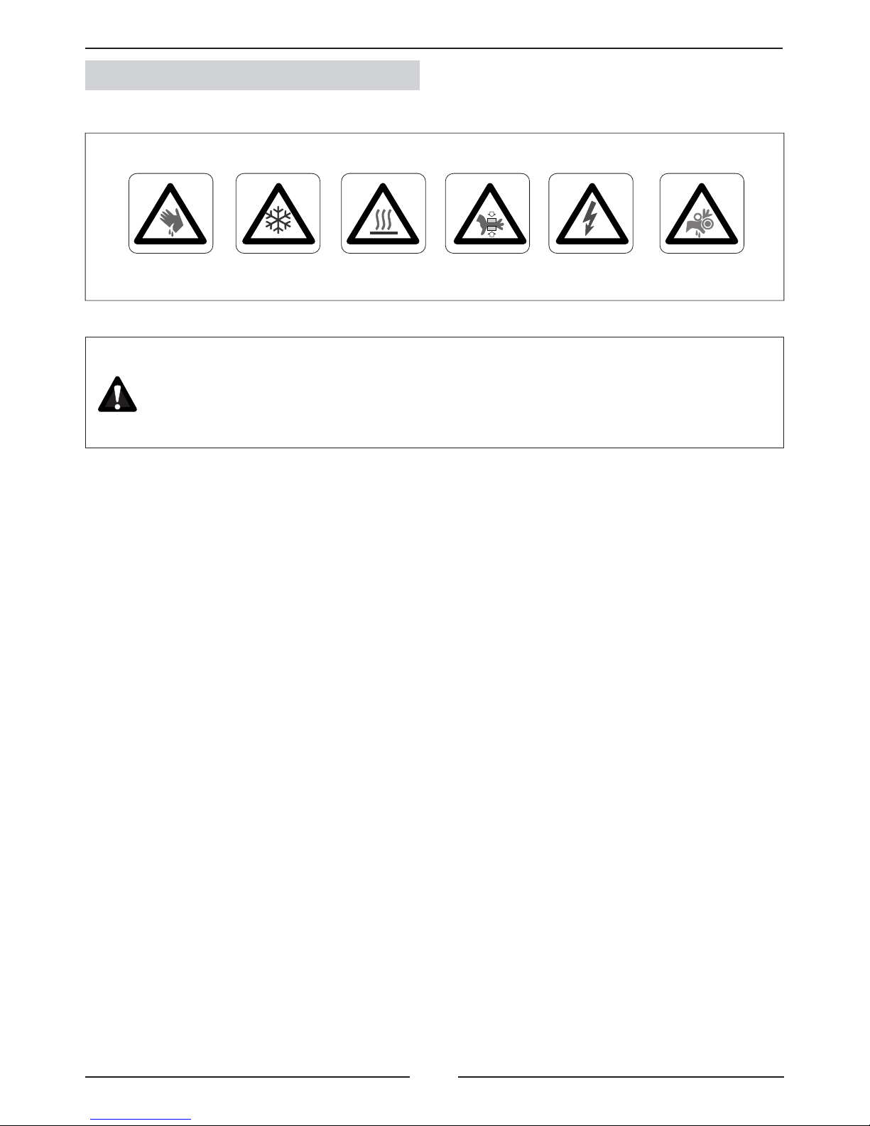
Abrasive
surfaces
Risk of injury by
moving objects
High
temperatures
Low
temperatures
Risk of injury by
rotating objects
Electrical
voltage
ELECTRICAL CONNECTIONS
Make sure to switch off the power before installing, repairing or carrying out maintenance on the unit,
in order to prevent serious electrical injury.
Keep local and national legislation in mind when installing the unit.
Standard Guidelines to Lennox equipment
All technical data contained in these operating instructions, including the diagrams and technical description remains
the property of Lennox and may not be used (except for the purpose of familiarizing the user with the equipment),
reproduced, photocopied, transferred or transmitted to third parties without prior written authorization from Lennox.
The data published in the operating instructions is based on the latest information available. We reserve the right to
make modications without notice.
We reserve the right to modify our products without notice without obligation to modify previously supplied goods.
These operating instructions contain useful and important information for the smooth operation and maintenance of
your equipment.
The instructions also include guidelines on how to avoid accidents and serious damage before commissioning the
equipment and during its operation and how to ensure smooth and fault-free operation. Read the operating instructions
carefully before starting the equipment, familiarize yourself with the equipment and handling of the installation and
carefully follow the instructions. It is very important to be properly trained in handling the equipment. These operating
instructions must be kept in a safe place near the equipment.
Like most equipment, the unit requires regular maintenance. This section concerns maintenance and management
personnel.
If you have any queries or would like to receive further information on any aspect relating to your equipment,
do not hesitate to contact us.
POINTS TO BEAR IN MIND
DANGER AND WARNING SIGNS
3
1 ºC
2 ºC
1 ºC
2 ºC
1 ºC
2 ºC
1 ºC
2 ºC
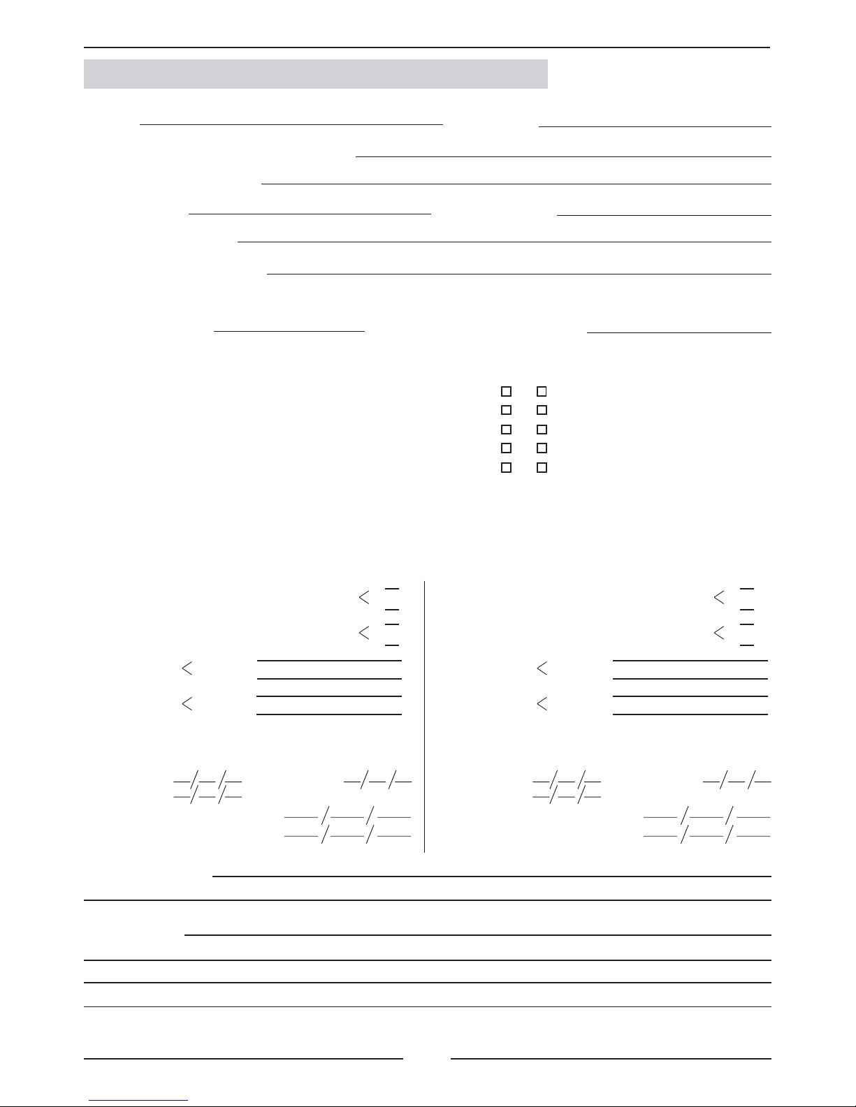
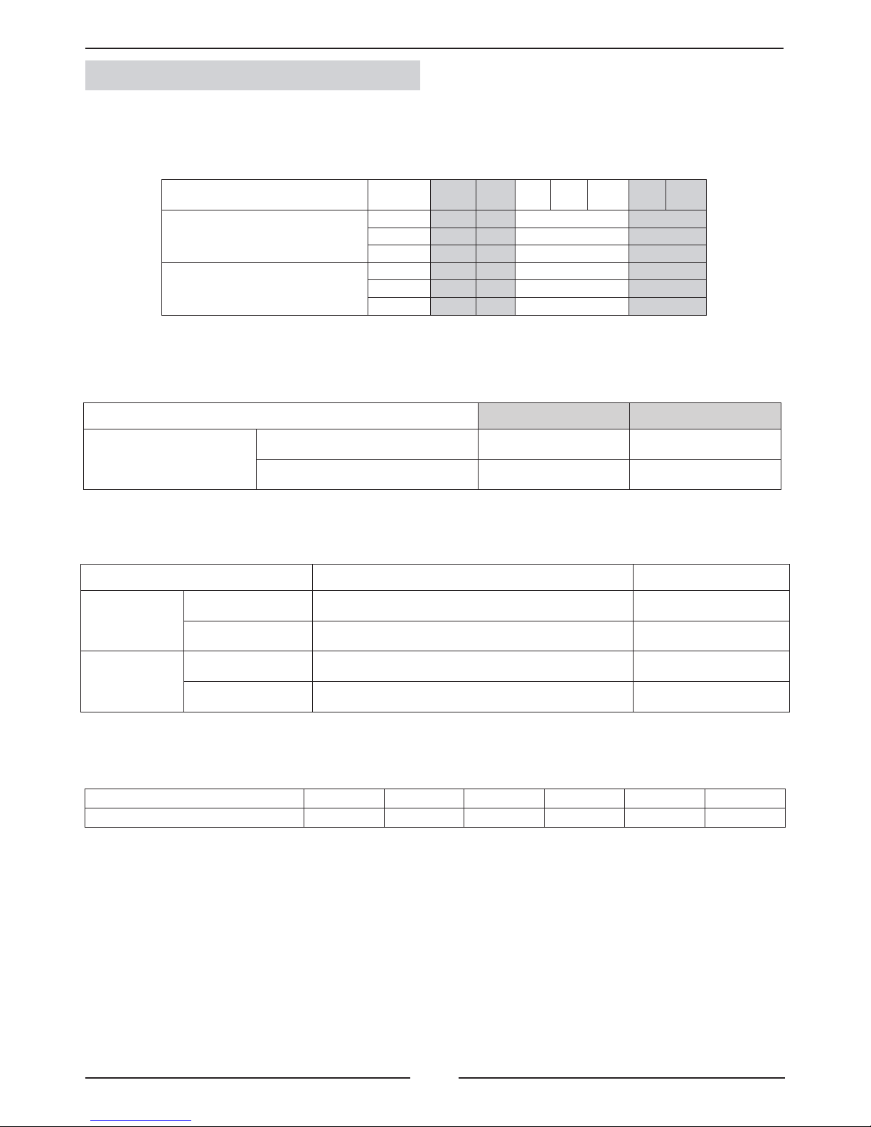
DATA PAGE FOR UNIT COMMISSIONING
UNIT:
INSTALLER TEL:INSTALLER:
CONTROL PANEL IDENTIFICATION CODE:
INSTALLATION ADDRESS:
SERIAL Nr:
CHECKS:
DATE OF COMMISSIONING:
SUPPLY VOLTAGE:
RATED VOLTAGE OF THE UNIT:
UNIT ON SHOCK ABSORBERS
DRAINAGE WITH TRAP
MAIN POWER SUPPLY CONNECTION
CONTROL PANEL CONNECTION
COMPRESSOR OIL LEVEL INDICATOR
YES NO
DATA INPUT:
COOLING CYCLE
Air intake temperature to the outdoor coil:
Air output temperature to the outdoor coil:
High pressure:
Low pressure:
circuit 1
circuit 2
circuit 1
circuit 2
Air intake temperature to the outdoor coil:
Air output temperature to the outdoor coil:
High pressure:
Low pressure:
circuit 1
circuit 2
circuit 1
circuit 2
HEATING CYCLE
ELECTRIC POWER CONSUMPTION (Amps)
Compressor 1
Compressor 3
Outdoor fan section 1
Outdoor fan section 2
Options installed:
Comments:
Compressor 2
Compressor 2
INSTALLER ADDRESS:
Compressor 1
Compressor 3
Outdoor fan section 1
Outdoor fan section 2
4
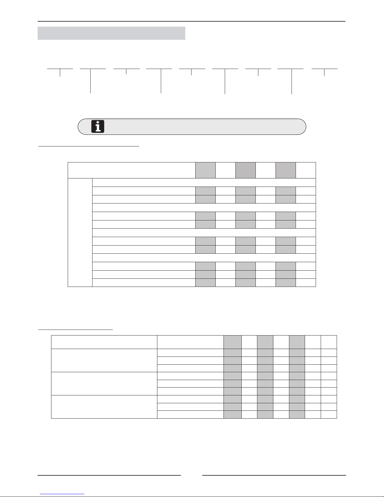
F M C 015 S N M 1 M
010 012 015 020 025 030
170 174 250 268 322 338
175 179 255 273 327 343
112 116 165 159 202 208
117 121 170 164 207 213
58 58 85 109 121 131
58 58 85 109 121 131
12 12 12 14 15 15
24 24 24 28 30 30
7 7 7 7 8 8
10
230V I
10 12 15 20 25 30
5,5 5,3 6,6 7,8 10,4 12,6 14,2
31,7 13,7 16,0 18,6 23,6 30,0 31,0
90,2 34,1 39,7 49,0 75,3 82,3 86,9
0,4 0,4 0,4 0,8 1,0 1,3 1,3
2,6 2,6 2,6 2,8 4,3 4,3 4,3
1,7 1,7 1,7 1,8 2,8 2,8 2,8
5,1 4,9 6,1 7,0 9,4 11,3 13,0
29,1 11,1 13,4 15,8 19,3 25,7 26,7
87,6 31,5 37,1 46,2 71,0 78,0 82,6
1.- GENERAL CHARACTERISTICS
1.1.- PHYSICAL DATA
Unit
FLATAIR
C: Cooling only
H: Heat pump
X: Cooling only / Heat pump
Type of refrigerant
M: R-410A
Approximate cooling
capacity in kW
M: Compact unit
S: Outdoor unit
I: Indoor unit
S: One Circuit
- - -
Number
of revision
M: 400V/3/50
FMC: Cooling only unit R-410A.
FMH: Heat pump unit R-410A.
1.2.- ELECTRICAL DATA
ELECTRICAL CONSUMPTION
WEIGHTS OF THE UNITS AND OPTIONS
UNIT
PACKAGE UNIT (INDOOR+ OUTDOOR)
Maximum power (KW)
Maximum current (A)
Starting current (A)
INDOOR UNIT
Maximum power (KW)
Maximum current (A)
Starting current (A)
OUTDOOR UNIT
Maximum power (KW)
Maximum current (A)
Starting current (A)
MODELS
Net weight
Kg.
Package unit
Cooling only FMC
Heat pump FMH
Outdoor unit
Cooling only FSC
Heat pump FSH
Indoor unit
Cooling only FIC
Heat pump FIH
Opcions
Free-cooling 1 damper
Free-cooling 2 dampers
Electrical heater
5
10
230V I
10 12 15 20 25 30
3 3 4,5 7,5
6 6 6 9
9 9 12
13,0 7,5 11,3 18,8
26,1 15 15 22,5
- 22,5 22,5 30
32ºC BS / 23ºC BH 21ºC BS / 15ºC BH
27ºC BS 15ºC BS
-12ºC
10 12 15 20 25 30
45 43 45 44 44 41
1.- GENERAL CHARACTERISTICS
1.2 .- ELECTRICAL DATA
(*) With option kit low temperature 0ºC. (**) With option kit low temperature -15ºC.
DB: Dry bulb temterature WB: Wet bulb temperature
1.3.- OPERANTING LIMITS
(*) Active CL40 parmeter to operate at 0º (**) With option kit low temperature -15ºC.
Electrical consumptions to add to the unit indoor and to the set
ELECTRICAL HEATER
Maximum power (KW)
Standard
Medium
High
Maximum current (A)
Standard
Medium
High
OPERATING LIMITS
(HEAT PUMP)
MAXIMUM TEMPERATURES MINIMUM TEMPERATURES
COOLING CYCLE
OPERATION
INDOOR TEMPERATURE
OUTDOOR TEMPERATURE
Table 1
+15ºC STANDARD UNIT
0ºC (*) -15ºC (**)
HEATING CYCLE
OPERATION
INDOOR TEMPERATURE
OUTDOOR TEMPERATURE
25ºC (With 20º indoor temperature. Models 10-15-20-30)
23ºC (With 20º indoor temperature. Models 12-25)
OPERATING LIMITS (COOLING ONLY) MAXIMUM TEMPERATURES MINIMUM TEMPERATURES
COOLING CYCLE OPERATION
INDOOR TEMPERATURE
32ºC BS / 23ºC BH 21ºC BS / 15ºC BH
OUTDOOR TEMPERATURE
Table 1
+15ºC UNIDAD ESTÁNDAR
0ºC (*) -15ºC (**)
Table 1
Maximum outdoor temperature
6
10 12 15 20 25 30
0 2350 2300 3575 4850 5750 5500
10 2275 2250 3495 4785 5730 5455
20 2240 2200 3410 4715 5705 5405
30 2190 2150 3330 4645 5670 5350
40 2140 2100 3250 4575 5630 5285
50 2080 2040 3170 4500 5580 5220
60 2025 1975 3095 4425 5530 5140
70 1975 1925 3020 4345 5470 5060
80 1925 1860 2945 4260 5405 4965
90 1840 1800 2875 4175 5330 4870
100 1775 1730 2800 4090 5250 4765
110 1625 1650 2735 4000 5165 4655
120 1500 2665 3910 5075 4540
130 2600 3815 4975 4415
140 2535 3720 4870 4285
150 2470 3620 4755 4150
160 2410 3520 4640 4005
170 3415 4515 3855
180 3310 4380 3695
190 3200 4245
200 3090 4100
210 3945
220 3790
230 3625
240 3455
10 12 15 20 25 30
0 3500 3400 4500 5650 6000 5850
10 3410 3325 4460 5550 5920 5755
20 3300 3160 4410 5450 5840 5665
30 3190 3075 4360 5350 5760 5575
40 3080 2980 4310 5250 5680 5485
50 2970 2890 4250 5150 5600 5400
60 2840 2790 4190 5050 5520 5315
70 2700 2690 4125 4945 5445 5235
80 2560 2580 4055 4840 5365 5155
90 2410 2400 3980 4735 5290 5075
100 2350 3905 4630 5210 5000
110 3825 4525 5135
120 3740 4420 5060
130 4315 4985
140 4205 4910
150 4095 4835
160 4760
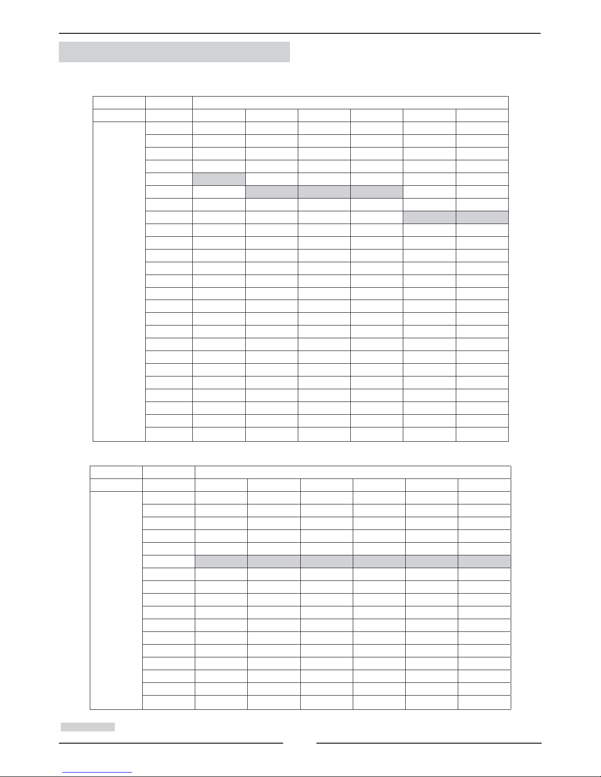
1.- GENERAL CHARACTERISTICS
1.4.- FAN PERFORMANCES
Airow (m3/h)
UNITS
Available
static
pressure
(Pa)
Airow (m3/h)
UNITS
Available
static
pressure
(Pa)
OUTDOOR UNITS
INDOOR UNITS
Nominal airow
7
IS
CH
PT
OS
LP
HP
LP
HP
PT
C
H
IS
OS
IS
LP HP
PT
OS
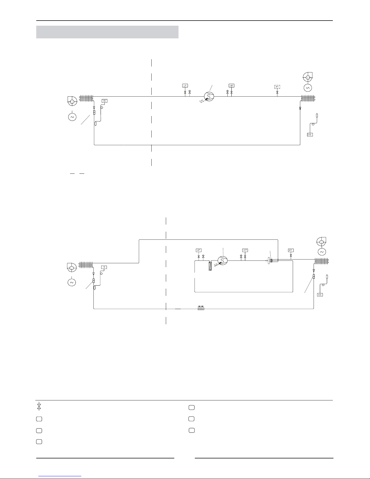
1.- GENERAL CHARACTERISTICS
1.8.- PIPING DRAWINGS COOLING ONLY UNITS 10-12-15
OPTION ELEMENT
Scroll compressor
Fan
Fan motor
Coil
Coil
Fan
Pressure gauge. (5/16” to be tted by the installer).
Liquid-gas pipe sensor
Low pressure switch
High pressure switch
Crank case heater. (Low ambient 0ºC or -15ºC option for cooling only units).
Pressure transducer (Low ambient 0ºC or -15ºC option for cooling only units).
Outdoor temperature sensor
Scroll compressor
4-way valve
Filter drier
Fan motor
Coil
Coil
Orice
Orice
Orice
Suction
Acumulator
HEAT PUMP UNITS 10-12-15
OUTDOOR UNIT
INDOOR UNIT
OUTDOOR UNIT
INDOOR UNIT
8
IS
CH
PT
OS
LP
HP
LP
HP
PT
(ELEMENTO OPCIONAL)
C
H
IS
OS
IS
LP HP
PT
OS
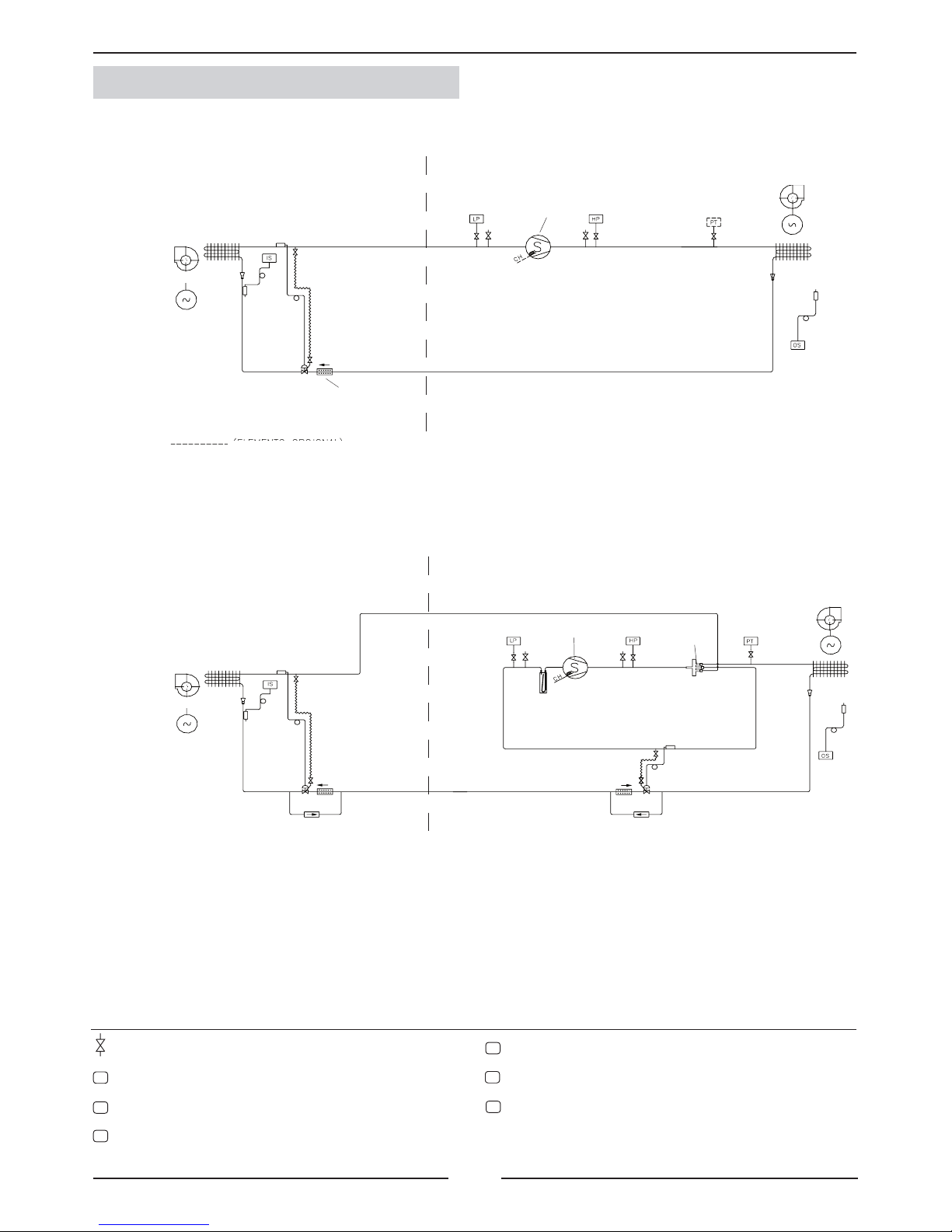
1.- GENERAL CHARACTERISTICS
1.8.- PIPING DRAWINGS HEAT PUMP UNITS 20-25-30
OPTION ELEMENT
Scroll compressor
Fan
Expansion valve
Filter drier
Fan motor
Coil
Coil
Scroll compressor
Fan
Pressure gauge. (5/16” to be tted by the installer).
Liquid-gas pipe sensor.
Low pressure switch.
High pressure switch.
Crank case heater. (Low ambient 0ºC or -15ºC option for cooling only units).
Pressure transducer, circuit 1.(Low ambient 0ºC or -15ºC option for cooling only
units).
Outdoor temperature sensor
Scroll compressor
4-way valve
Fan
Expansion valve
Filter drier
Fan motor
Coil
Coil
Check valve
Expansion valve
Check valve
HEAT PUMP UNITS 20-25-30
Suction
Acumulator
Filter drier
OUTDOOR UNIT
INDOOR UNIT
OUTDOOR UNIT
INDOOR UNIT
9
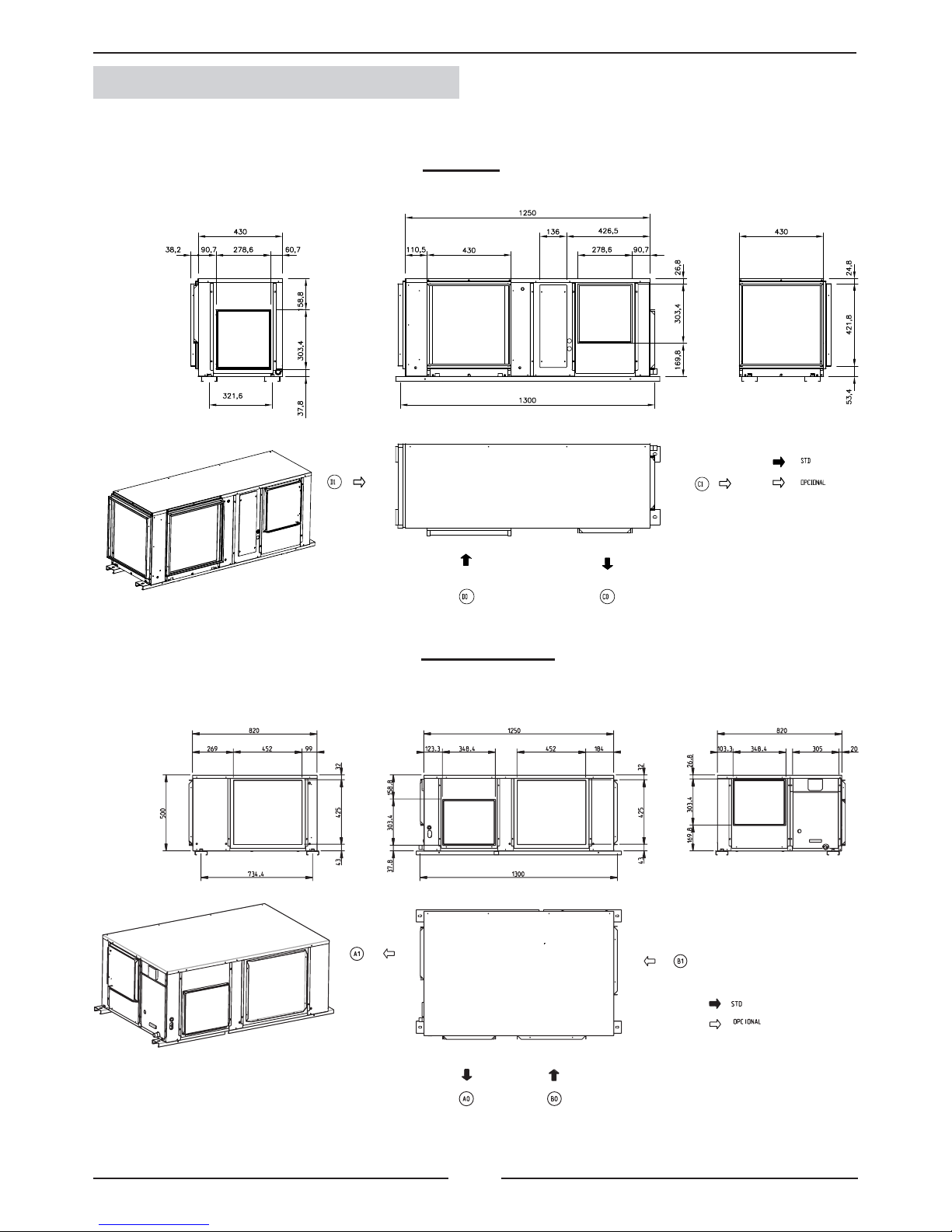
FIX 10-12
FSC / FSH 10-12
1.- GENERAL CHARACTERISTICS
1.5.- UNIT DIMENSIONS
 Loading...