


FLATAIR
FLCK / FLHK
English/03-2005
INSTALLATION
OPERATION &
MAINTENANCE MANUAL

1
WARNING: Read this manual before installation, reparation o maintenance works.
1.1.- PHYSICAL DATA
1.2.- ELECTRICAL DATA
1.3.- FAN SERVICES
1.4.- OPERATING LIMITS
1.5.- UNIT DIMENSIONS
1.6.- SIZES OF STANDARD AND OPTIONAL OPENINGS
1.7.- AVAILABLE OPTIONS
DATA PAGE FOR UNIT COMMISSIONING
4.- MAINTENANCE
4.1.- PREVENTIVE MAINTENANCE
4.2.- CORRECTIVE MAINTENANCE
4.3.- FAILURE DIAGNOSIS
2.- INSTALLATION
3.- COMMISSIONING AND OPERATION
1.- GENERAL CHARACTERISTICS
PAGE
PAGE
PAGE
PAGE
4
5
6
7
8-11
12-15
16-17
18
18
19-20
21
22
22
23-24
25
26
27
28
29
TABLE OF CONTENTS
PAGE 3
2.1.- PRELIMINARY PREPARATIONS
2.2.- UNIT RECEPTION
2.3.- OPTIONAL TASKS PRIOR TO UNIT INSTALLATION:
CHANGING THE POSITION OF BLOWERS AND AIR INTAKE
2.4.- UNIT LOCATION AND WEIGHT DISTRIBUTION
2.5.- INSTALLATION CLEARANCES
2.6.- DRAINS
2.7.- ELECTRICAL CONNECTIONS
3.1.- PRELIMINARY CHECKS
3.2.- STEPS TO FOLLOW FOR COMMISSIONING THE UNIT
POINTS TO KEEP IN MIND
PAGE 2
Lennox have been providing environmental solutions since 1895, our range of FLATAIR continues to meet the standards that
have made LENNOX a household name. Flexible design solutions to meet YOUR needs and uncompromising attention to
detail. Engineered to last, simple to maintain and Quality that comes as standard. Information on local contacts at
www.lennoxeurope.com.
All the technical and technological information contained in this manual, including any drawing and technical descriptions
provided by us, remain the property of Lennox and must not be utilised (except in the operation of this product), reproduced,
issued to or made available to third parties without the prior written agreement of Lennox.

2
Make sure to open the power off switch before to install, repair or make maintenance works in the unit, in order to
prevent serious electrical injuries.
To install the unit, keep in mind local and national legislation.
ELECTRICAL CONNECTIONS
ATTENTION - WARNING
Risk of injury with
rotating objects
Low
temperatures
High
temperatures
Risk of injury with
moving objects
Electrical
voltage
Abrasive
surfaces
FILTER CLEANING
Check the air filter and make
sure it is not blocked with dust
or dirt.
If the filter is dirty, wash it in a bowl with neutral
soap and water, drying it in the shade before
inserting it in the unit.
All technical data contained in these operating instructions including the diagrams and technical description remains the property
of Lennox and may not be used (except for the purpose of familiarizing the user with the equipment), reproduced, photocopied,
transferred or transmitted to third parties without prior written authorization from Lennox .
The data published in the operating instructions is based on the latest information available. We reserve the right to make
modifications without notice.
We reserve the right to modify our products without notice without obligation to modify previously supplied goods.
These operating instructions contain useful and important information for the smooth operation and maintenance of your
equipment.
The instructions also include guidelines on how to avoid accidents and serious damage before commissioning the equipment
and during its operation and how to ensure smooth and fault-free operation. Read the operating instructions carefully before
starting the equipment, familiarize yourself with the equipment and handling of the installation and carefully follow the instructions.
It is very important to be properly trained in handling the equipment. These operating instructions must be kept in a safe place
near the equipment.
Like most equipment, the unit requires regular maintenance. This section concerns the maintenance personnel and management.
If you have any queries or would like to receive further information on any aspect relating to your equipment, do not hesitate
to contact us.
The air filter cleaning operations do not
require technical service; however when
an electrical or mechanical operation
is required call an Engineer.
Electric shock hazard can cause injury
or death. Before attempting to perform
any service or maintenance on the
unit, turn OFF the electrical power,
and check that the fan has stopped.
Standard Guidelines to Lennox equipment
POINTS TO KEEP IN MIND
DANGER AND WARNING SIGNS

3
UNIT:
SERIAL Nr.:
INSTALLATION ADDRESS:
INSTALLER:
INSTALLER TEL.:
CHECKS:
SUPPLY VOLTAGE:
DATA INPUT:
Air Intake Temperature, Outdoor Coil:
ºC
DATE OF COMMISSIONING:
INSTALLER ADDRESS:
RATED VOLTAGE OF THE UNIT:
YES NO
GENERAL POWER SUPPLY CONNECTION
CONTROL PANEL CONNECTION
COLD CYCLE
HEATING CYCLE
Air Output Temperature, Outdoor Coil:
ºC
Air Intake Temperature, Indoor Coil:
ºC
Air Output Temperature, Indoor Coil:
ºC
High Pressure:
Low Pressure:
Options Installed:
ºC
ºC
ºC
High Pressure:
Low Pressure:
ºC
Comments:
COMPRESSOR OIL LEVEL INDICATOR
UNIT ON SHOCK ABSORBERS
DRAINAGE WITH TRAP
CLEAN INTERIOR AIR FILTER
CONTROL PANEL IDENTIFICATION CODE
DATA PAGE FOR UNIT COMMISSIONING
ELECTRIC POWER CONSUMPTION
Compressor
Fan outdoor section
Compressor
Fan outdoor section
Fan indoor section Fan indoor section
(Amps)
Air Intake Temperature, Outdoor Coil:
Air Output Temperature, Outdoor Coil:
Air Intake Temperature, Indoor Coil:
Air Output Temperature, Indoor Coil:

4
1.- GENERAL CHARACTERISTICS
FLHA: Heat pump unit R-22
FLCK: Cooling only unit R-407C
FLHK: Heat pump unit R-407C
1.1.- PHYSICAL DATA
Cooling capacity
COMPRESSOR
Nr. / Type
FAN OUTDOOR SECTION
NET WEIGHT
DB.- Dry bulb temperature
WB.- Wet bulb temperature
9,8 11,8
kW
Kg
15,3 19,5
1 / Scroll 1 / Scroll 1 / Scroll 1 / Scroll
22,0 28,1
1 / Scroll 1 / Scroll
26,3
1 / Scroll
10
Heating capacity
10,0 12,0
kW
15,5 20,2 22,5 28,727,0
12 16 22 24 28 30
Cooling capacity
9,4 11,3
kW
14,7 19,2 21,0 27,6
Heating capacity
kW
10,3 12,3 15,6 20,0 22,8 29,8
FLHA 12FLHA 10 FLHA 16 FLHA 22 FLHA 24 FLHA 28
FLHA 30
26,0
27,0
FLCK 12
FLHK 12
FLCK 10
FLHK 10
FLCK 16
FLHK 16
FLCK 22
FLHK 22
FLCK 24
FLHK 24
FLCK 30
FLHK 30
FLCK 28
FLHK 28
(*) Air intake temperature in the indoor exchanger: 27ºC DB/19ºC WB
(*) Air intake temperature in the outdoor exchanger: 35ºC DB
(**) Air intake temperature in the indoor exchanger: 20ºC DB / 12ºC WB
(**) Air intake temperature in the outdoor exchanger: 7ºC DB / 6ºC WB
Refrigerant charge R-22
Refrigerant charge
R-407C
2240 2560 3550 5000
7500 82008000
2620 2920 4000 5500
--- 7000---
Maximum air flow
24002350 3750 4350
Maximum available pressure
100 90 120 150
Pa
4500 5250
160 100
5000
120
m /h.
3
34003500 4950 5900 6600 6400
6400
Minimum air flow
(1)
m /h.
3
Maximum air flow
16501500 2400 3200
Maximum available pressure
120 110 160 180
Pa
4000 4500
240 180
4250
200
m /h.
3
2300
2350
3700
5350
6300 6000
6000
Minimum air flow
(1)
m /h.
3
FAN INDOOR SECTION
(1) With admissible minimum air flow.
210205 285 330 410 435
430
205200 280 325 405 430
425
Kg
UNIT MODELS
UNIT MODELS
gr.
2900 3100 3900 5400 8400 87008600
gr.
Cooling only units FLC
Heat pump units FLH
(*)
(**)
(*)
(**)
FLCK
FLHK
Application
C: Cooling only
H: Heat pump
Type of Refrigerant
A: R-22
K: R-407C
Unit size.
Approximate cooling
capacity in kW
UNIT MODELS
FL C K 22
Type of unit
Horizontal compact
FLATAIR

5
1.- GENERAL CHARACTERISTICS
V/f (50 Hz)
V/f (50 Hz)
1.2.- ELECTRICAL DATA
3,21
kW
3,84 5,65 7,376,25
Total power in Cooling cycle
Total power in heating cycle
Voltage
230V-400V/ 3Ph
230V/ 1Ph
FLHA 12FLHA 10 FLHA 16 FLHA 22 FLHA 24 FLHA 28 FLHA 30
FLCK 12
FLHK 12
FLCK 10
FLHK 10
FLCK 16
FLHK 16
FLCK 22
FLHK 22
FLCK 24
FLHK 24
FLCK 30
FLHK 30
FLCK 28
FLHK 28
kW
kW
kW
kW
Maximum current
Rated absorbed power
2,03 2,54
kW
2,94 3,70 4,85 6,485,48
Total power in cooling cycle
Total power in heating cycle
Voltage
230V-400V/ 3Ph
230V/ 1Ph
kW
kW
0,38
0,38
kW
0,90 1,30 1,35 1,351,35
0,52 0,52
kW
1,10 1,60 1,60 1,601,60
Maximum current
Total current
Start up current
0,38 0.38 0,90 1,30 1,35 1,351,35
0,52 0,52 1,10 1,60 1,60 1,601,60
2,60 3,41
kW
4,11 5,02 5,85 8,837,41
Rated absorbed power
2,26
3,60
2,79 3,68
kW
4,41 5,20 6,05 9,257,43
Total Current
Start up current
3,69
4,58
6,41 8,10
3,16 4,11 5,60 6,74
9,00 12,20
8,60 10,32
10,38
9,20
UNIT MODELS
UNIT MODELS
A
A
3,50
4,31
6,11 7,92
16,7/7,2 19,3/8,7 19,9/11,5 22,4/12,9
2,93 3,44 4,94 6,60
8,80 11,78
7,80 9,43
25,3/14,6 36,5/21,0
10,36
8,43
28,5/16,3
A
7/4 7,4/4,3
A
52,0/30,044,0/25,439,8/23,037,2/21,531,7/18,3
25,0/14,422,4/12,9
A
24,3
2,6
2,6
7,4/4,3 7,4/4,3 7,4/4,3
3,1 3,1
4,8/2,8 7,4/4,3 8,1/4,7 8,1/4,7 8,1/4,7
18,6
A
A
A
A
52,0/30,044,0/25,439,8/23,037,2/21,531,7/18,3
25,0/14,422,4/12,9
A
24,3
7/4 7,4/4,3
2,6
2,6
7,4/4,3 7,4/4,3 7,4/4,3
3,1 3,1
4,8/2,8 7,4/4,3 8,1/4,7 8,1/4,7 8,1/4,7
16,7/7,2 19,3/8,7 19,9/11,5 22,4/12,9 25,3/14,6 36,5/21,028,5/16,3
18,6
Fan outdoor section
Fan indoor section
Compressor (heating cycle)
Fan outdoor section
Fan indoor section
Compressor
Fan outdoor section
Fan indoor section
Compressor (cooling cycle)
Compressor (heating cycle)
Compressor (Cooling cycle)
Compressor
Fan outdoor section
Fan indoor section
240/136226/132182/108
193/110
145/73104/5697/52
101
240/136226/132182/108193/110145/73104/5697/52
101

6
1.3.- FAN SERVICES
1.- GENERAL CHARACTERISTICS
m /h
3
AIR FLOW
m /h
3
AIR FLOW
6300 6000 60002350 2300 3700 53500
NOMINAL
AIR FLOW
10
20
30
40
50
60
70
80
90
100
110
120
130
140
160
180
200
220
240
6225 5925 59252275 2250 3625 5200
6140 5860 58602240 2200 3550 5090
6100 5800 58002190 2150 3475 4960
6010 5725 57252140 2100 3400 4850
5930 56502080 2040 3320 4725
5875 56002025 1975 3240 4610
5790
5600
55101975 1925 3160 4505
5710
5510
54401925 1860 3090 4400
5620
5440
53501840 1800 3000 4300
5540
5350
52751775 1730 2915 4160
5450
5275
51901625 1650 2825 4040
5350
5190
51001500 2750 3925
5320
5100
5000--- 2670 3800
5150
5000
49102580 3700
4940 4700 47002400 3525
4700 4500 45003200
4425 4250
4175
4000
6600 6400 64003500 3400 4950 59000
10
20
30
40
50
60
70
80
90
100
110
120
130
140
150
160
6490 6300 63003410 3325 4850 5800
6340 6200 62003300 3160 4750 5700
6225 6100 61003190 3075 4625 5600
6100 5980 59803080 2980 4525 5495
5960 5870 58702970 2890 4425 5390
5850 5725 57252840 2790 4325 5280
5710 5600 56002700 2690 4225 5180
5600 5490 54902560 2580 4125 5075
5480 5375 53752410 2400 4040 4975
5350 5250 52502350 3940 4875
5200 51003840 4775
5090 50003750 4675
49504575
48004460
46504350
4500
MODELS
10 12 16 22 24 28 30
10 12 16 22 24 28 30
INDOOR UNITS
OUTDOOR UNITS
---
---
---
---
---
---
---
---
---
---
---
---
---
---
---
---
---
---
---
---
---
---
---
---
---
---
5650
4910
AVAILABLE STATIC PRESSURE Pa.
---
---
---
---
---
---
---
---
---
---
---
---
---
---
---
---
---
---
---
---
---
---
---
---
---
---
---
---
MODELS
NOMINAL
AIR FLOW
AVAILABLE STATIC PRESSURE Pa.
Keep in mind reduction on air flow and static pressure services if you use mufflers or external air filter.
NOTE:

7
1.- GENERAL CHARACTERISTICS
1.4.- OPERATING LIMITS
INDOOR
TEMPERATURE
MAXIMUM TEMPERATURES MINIMUM TEMPERATURES
32ºC DB / 23ºC WB
COOLING CYCLE
OPERATION
21ºC DB / 15ºC WB
OUTDOOR
TEMPERATURE
0ºC (MODELS 22/24/28/30)
19ºC (MODELS 10/12/16) (*)
-10ºC (**)
INDOOR
TEMPERATURE
MAXIMUM TEMPERATURES MINIMUM TEMPERATURES
32ºC DB / 23ºC WB
21ºC DB / 15ºC WB
OUTDOOR
TEMPERATURE
INDOOR
TEMPERATURE
27ºC DB
15ºC DB
OUTDOOR
TEMPERATURE
24ºC DB / 18ºC WB
-10ºC DB / -11ºC WB
0º C (MODELS 22/24/28/30)
19º C (MODELS 10/12/16) (*)
-10ºC (**)
COOLING CYCLE
OPERATION
HEATING CYCLE
OPERATION
OPERATING LIMITS FOR (COOLING ONLY) UNITS
OPERATING LIMITS FOR (HEATING PUMP) UNITS
DB.- Dry Bulb Temperature
WB.- Wet Bulb Temperature
(*) With condensation pressure control (optional), 0 ºC minimum outdoor operating temperature.
(**) With kit got gas bypass valve.
DEPENDING ON MODEL
(TABLE 1)
TABLE 1- COOLING CYCLE MAXIMUM OUTDOOR OPERATING TEMPERATURES
MODELS
Rated outdoor flow
Minimum outdoor flow
10 12 16 22 24 28 30
MODELS WITH REFRIGERANT R-407C
45
43
43
43
44
41
45
41
46
42
42
39
41
38
MODELS
Rated outdoor flow
Minimum outdoor flow
10 12 16 22 24 28 30
MODELS WITH REFRIGERANT R-22
48
46
48
45
47
45
48
46
48
44
46
42
44
40
(*) With condensation pressure control (optional), 0 ºC minimum outdoor operating temperature.
(**) With kit got gas bypass valve.
DEPENDING ON MODEL
(TABLE 1)

8
1.5.- UNIT DIMENSIONS MODELS 10-12
1.- GENERAL CHARACTERISTICS
Detail drawing of
unit anchor support
25
60
40
25
80
50
20 x12
Oval hole
F
1250
40
14
430
422
735
404
Air filter
OUTDOOR
SECTION
INDOOR
SECTION
SIDE A
SIDE B
SIDE C
SIDE D
SIDE C
SIDE D
25
Unit anchor
support
1250
109
430
280
90
159
303
495
Distance between holes 1300
184
452
425
32
1250
495
Drainage
outside thread
3/4'' Male
Electrical box
1250
820
349
27
303
305
25
Thermostat connection
Power supply
connection
123
20
SIDE A
SIDE B

9
249
422
500
32
1300
125
500
324
98
182
355
1300
595
595
1.5.- UNIT DIMENSIONS MODEL 16
1.- GENERAL CHARACTERISTICS
Detail drawing of
unit anchor support
25
60
40
25
80
50
20 x12
Oval hole
F
1330
1330
830
40
25
324
500
27
355
320
25
123
745
474
20
517
Thermostat connection
Power supply connection
Air filter
SIDE A
SIDE B
OUTDOOR
SECTION
INDOOR
SECTION
SIDE A
SIDE B
SIDE C
SIDE D
SIDE C
SIDE D
Drainage
outside thread
3/4'' Male
Unit anchor
support
Distance between holes 1350
25
Electrical box

10
262
462
497
36,5
1450
42
591
324
107
193
355
1450
595
595
1.5.- UNIT DIMENSIONS MODEL 22
Detail drawing of
unit anchor support
25
60
40
25
80
50
20 x12
Oval hole
F
1520
1520
900
40
26
324
620
92
814
593
SIDE A
SIDE B
SIDE A
SIDE B
SIDE C
SIDE D
SIDE C
SIDE D
47
355
25
300
32
515,5
OUTDOOR
SECTION
INDOOR
SECTION
Power supply
connection
Thermostat
connection
Air filter
Drainage
outside thread
3/4'' Male
Unit anchor
support
Distance between holes 1500
25
1.- GENERAL CHARACTERISTICS
Electrical box

11
490
398
1500
82
658
327
95
223,5
355
645
1500
645
410
1.5.- UNIT DIMENSIONS MODELS 24-28-30
Detail drawing of
unit anchor support
25
60
40
25
80
50
20 x12
Oval hole
1800
1800
1025
103
SIDE A
SIDE B
SIDE A
SIDE B
SIDE C
SIDE D
SIDE C
SIDE D
25
677
124
355
40
26
214
775
565,5
537
939
748
OUTDOOR
SECTION
INDOOR
SECTION
Thermostat
connection
Power supply
connection
Air filter
Drainage
outside thread
3/4'' Male
Unit anchor
support
Distance between holes 1550
1.- GENERAL CHARACTERISTICS
25
Electrical box

12
1.- GENERAL CHARACTERISTICS
If the unit is going to be hung using the
anchor supports and the optional air return
opening, the supports must be repositioned
so that the air filter may be removed.
To move the supports, unscrew them from
the inside and fix them again using the
holes located next to the initial position.
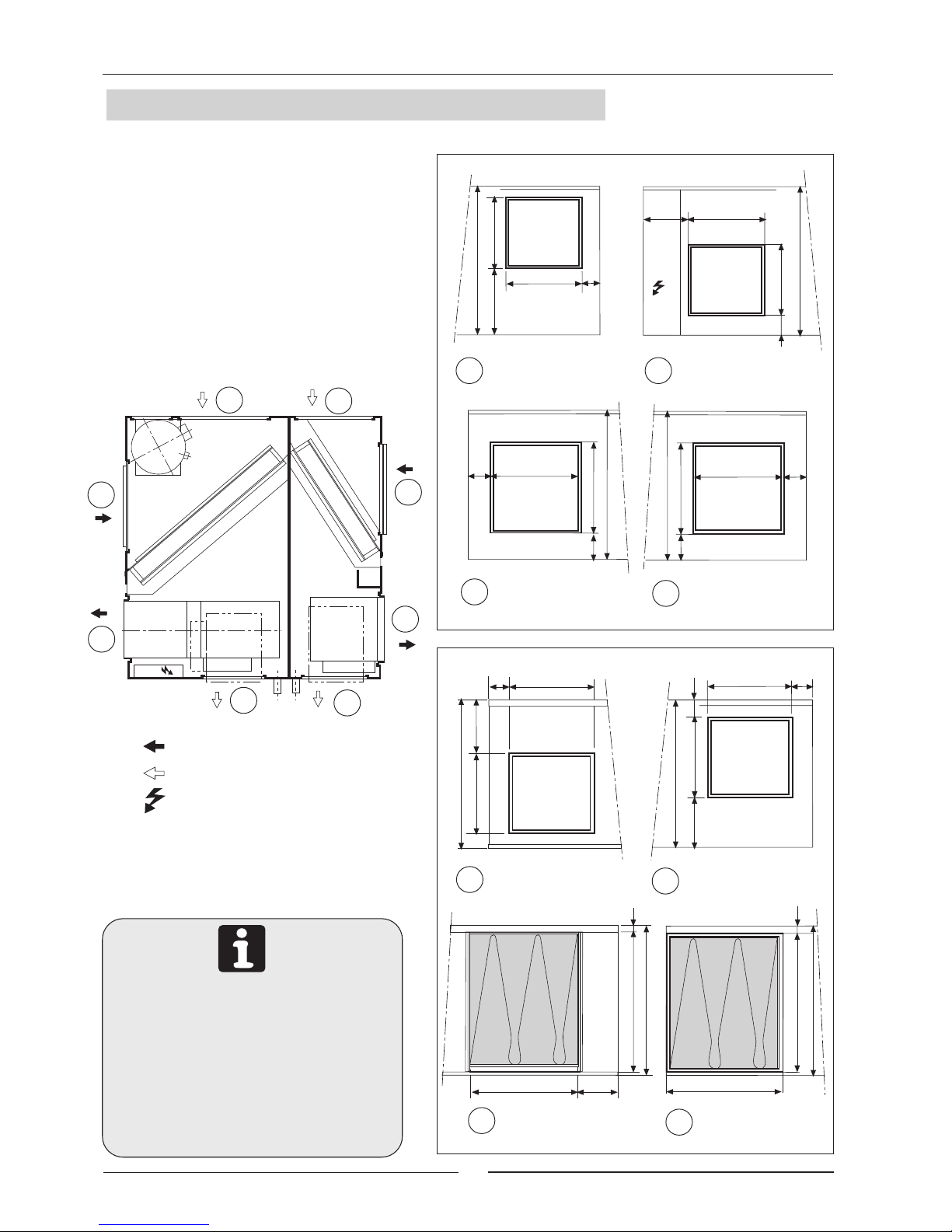
1.6.- UNIT OPENING SIZES MODELS 10-12
ELECTRICAL BOX
STANDARD CONFIGURATION
OPTIONAL CONFIGURATION
OUTDOOR COIL
COMPRESSOR
OUTDOOR
FAN
INDOOR
FAN
INDOOR COIL
E.B.
A0
A1
B0
B1
C1
C0
D0
D1
170
90
280
STANDARD
EXTRACTOR
OPENING
OPTIONAL
BLOWER
OPENING
303
349
495
349
495
303
38
368
303
495
170
OPTIONAL
EXTRACTOR
OPENING
OPTIONAL AIR
RETURN
OPENING
STANDARD
BLOWER
OPENING
495
14
STANDARD AIR
RETURN
OPENING
425
495
425
495
123
43
43
495
E.B.
452
269
452184
14
422
430
109
495
159
303
90
280
27
430
422
STANDARD
BLOWER
OPENING
OPTIONAL
BLOWER
OPENING
A1A0
B0
B1
OUTDOOR SECTION
C1
D1
INDOOR SECTION
C0
D0
1.- GENERAL CHARACTERISTICS
13
A1A0
C1
D1
C0
D0
B0
B1
If the unit is going to be hung using the
anchor supports and the optional air return
opening, the supports must be repositioned
so that the air filter may be removed.
To move the supports, unscrew them from
the inside and fix them again using the
holes located next to the initial position.
1.6.- UNIT OPENING SIZES MODEL 16
ELECTRICAL BOX
STANDARD CONFIGURATION
OPTIONAL CONFIGURATION
OUTDOOR COIL
COMPRESSOR
OUTDOOR
FAN
INDOOR
FAN
INDOOR COIL
E.B.
A0
A1
B0
B1
C1
C0
D0
D1
STANDARD
EXTRACTOR
OPENING
OPTIONAL
BLOWER
OPENING
OPTIONAL
EXTRACTOR
OPENING
OPTIONAL AIR
RETURN
OPENING
STANDARD
BLOWER
OPENING
STANDARD AIR
RETURN
OPENING
STANDARD
BLOWER
OPENING
OPTIONAL
BLOWER
OPENING
OUTDOOR SECTION
INDOOR SECTION
25
517
500
125
595
182
355
98
324
213
500
517
98
324
355
324
595
324
595
355
58
428
355
27
595
123
595
213
500
595
500
595
63
63
595
25
E.B.
422
304
422249

14
A0
A1
B0
B1
C1
C0
D0
D1
A1A0
C1
D1
C0
D0
B0
B1
1.- GENERAL CHARACTERISTICS
If the unit is going to be hung using the
anchor supports and the optional air return
opening, the supports must be repositioned
so that the air filter may be removed.
To move the supports, unscrew them from
the inside and fix them again using the
holes located next to the initial position.
1.6.- UNIT OPENING SIZES MODEL 22
ELECTRICAL BOX
STANDARD CONFIGURATION
OPTIONAL CONFIGURATION
STANDARD
EXTRACTOR
OPENING
OPTIONAL
BLOWER
OPENING
OPTIONAL AIR
RETURN
OPENING
STANDARD
BLOWER
OPENING
STANDARD AIR
RETURN
OPENING
STANDARD
BLOWER
OPENING
OPTIONAL
BLOWER
OPENING
OPTIONAL
EXTRACTOR
OPENING
OUTDOOR SECTION
INDOOR SECTION
26
515,5
591
42,5
595
193
355
107
324
591
15
193
107
324
355
324
595
324
595
355
391,5
355
595
515,5
595
26
92
595
193
497
595
497
595
61
61
193
E.B.
OUTDOOR COIL
COMPRESSOR
OUTDOOR
FAN
INDOOR FAN
INDOOR COIL
462
384
462262

15
A0
A1
B0
C1
C0
D0
D1
A1A0
B0
C1
D1
C0
D0
E.B.
1.- GENERAL CHARACTERISTICS
If the unit is going to be hung using the
anchor supports and the optional air return
opening, the supports must be repositioned
so that the air filter may be removed.
To move the supports, unscrew them from
the inside and fix them again using the
holes located next to the initial position.
1.6.- UNIT OPENING SIZES MODELS 24-28-30
ELECTRICAL BOX
STANDARD CONFIGURATION
OPTIONAL CONFIGURATION
STANDARD
EXTRACTOR
OPENING
OPTIONAL
BLOWER
OPENING
OPTIONAL AIR
RETURN
OPENING
STANDARD
BLOWER
OPENING
STANDARD AIR
RETURN
OPENING
STANDARD
BLOWER
OPENING
OPTIONAL
BLOWER
OPENING
OUTDOOR SECTION
INDOOR SECTION
26
565,5
658 82
645
223
355
95
327
658
107
213
258
327
355
410
645
410
645
355
355
645
565,5
645
26
537
40
645
645
214
214
103
103
677
222
OUTDOOR COIL
COMPRESSOR
OUTDOOR
FAN
INDOOR FAN
INDOOR COIL
16
1.- GENERAL CHARACTERISTICS
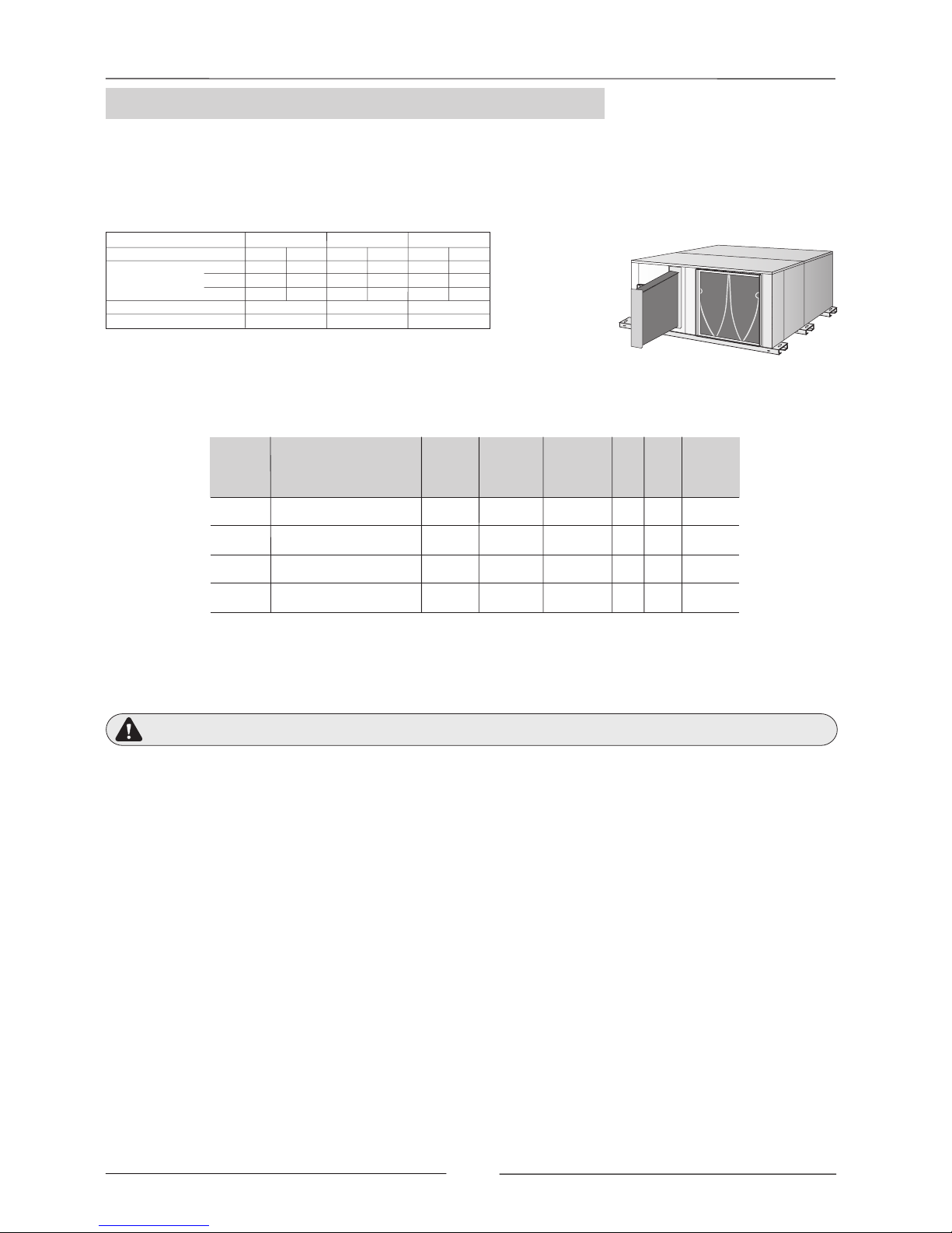
1.7.- AVAILABLE OPTIONS
HOT WATER COIL
It is based on a refrigerating coil made of copper tubing with aluminum swirl fins with
water inlet and outlet connections.
It is supplied mounted inside the unit as picture shows.
MAIN SWITCH
The main switch is located on the access panel to the electrical box in the outdoor section in such a way that the unit is
disconnected when the panel is opened.
(Refer to the size diagram on pages 8 to 11 to see the position of the electrical box access panel).
Check to make sure that the main switch is large enough to handle the current for the unit if electric heaters are installed.
PHASE SEQUENCER (THREE-PHASE UNIT)
The phase sequencer is located in the electrical box in the outdoor section, thus assuring that the unit will not begin operation
while the phase connection of the compressor is not correct. Should this occur, then just switch two phase connections.
ON/OFF CONDENSATION PRESSURE CONTROL (MODELS 10-12-16)
The condensation pressure control consists of a pressure switch, which starts and stops the outdoor fan regulating the
condensation temperature, thus the unit will be able to operate in the cooling cycle when the outdoor temperature is below
19ºC (until 0ºC).
HOT GAS BYPASS VALVE
The purpose of the BYPASS valve is to make it possible for the unit to operate at low outdoor temperatures (until -10°C), to
be used in cooling-only and heat-pump units in the cooling cycle.
It regulates the capacity of the compressor by injecting hot gas from the compressor discharge side to the evaporator.
CONTROL USING A PROGRAMMABLE CONTROLLER:
With the programmable controller option, the desired temperature can be programmed in the area 24 hours a day, 7 days a
week.
ELECTRIC HEATER
Optionally, these units can contain shielded element electric heating batteries that are mounted on the inside of the unit in the
schematic opposite.
The electric heater must get its power from the units electrical box.
A HEATING COIL FROZEN DUE TO LOW AMBIENT CONDITIONS IS NOT COVERED BY THE WARRANTY.
22,7
MODELS LFXO 10
MAXIMUM
CURRENT
(A)
230 / III
400 / III
POWER kW
12-16-22
7
WEIGHTS Kg (*)
STAGES
11
6
15,1
8,7913,1
7
24-28-30
8
1
7,5
18,9
10,9
12
30,2
17,4
6
15,1
8,7
9
22,7
13,1
230 / I
---- ---- ---- ----26,1 ----
(*) Add to the unit's weight.
PROTECTION AGAINST FREEZING:
Use glycol water. GLYCOL IS THE ONLY EFFECTIVE PROTECTION AGAINST FREEZING.
Regulation components should be used and in addition security components if they are needed.
Drain the installation. You must ensure that the manual or automatic air vents have been installed on all high points in the
system. In order to drain the system check that all the drain cocks have been installed on all low points of the system.
DIFFERENCE IN TEMPERATURES
BETWEEN HOT WATER INTAKE
AND THE AIR WHICH ENTERS
THE COIL
50ºC 60ºC 70ºC
WATER
FLOW
L/H
WATER COIL
PRESSURE
DROP
kPa
AIR
PRESSURE
DROP
Pa
10-12
CAPACITY IN W
CAPACITY IN W
CAPACITY IN W
9000 11000 12800
15000 18000 21000
24500 29500 34400
500
1000
1500
0,5
1,5
3
35-30
30-25
25-20
22
24-28-30
16
CAPACITY IN W
14500 17500 20400 1000 1,5
35-30
Nr
ROWS
2
2
2
2
WEIGHT
Kg
4
6
7
5
WATER
OUTLET
DIAMETER
Inches
3/4"
3/4"
3/4"
3/4"
MODELS
FLC/FLH
INDOOR UNIT
nominal-minimum
air flow

17
1.- GENERAL CHARACTERISTICS
1.7.- AVAILABLE OPTIONS
REMOTE ROOM-TEMPERATURE SENSOR, REMOTE DUCT SENSOR
These sensors may be used in conjunction with remote controller, allowing the controller to be mounted in a room away from
the conditioned space.
- REMOTE DUCT SENSOR: The sensor will be located in the return-air duct, detecting the air temperature of the
air being air-conditioned.
- REMOTE ROOM-TEMPERATURE SENSOR: The sensor will be placed in the area to be air-conditioned.
FREECOOLING THERMOSTAT KIT
The Freecooling Thermostat Kit will only operate in cooling-only or heat-pump units in the cooling cycle. This is an energy
saving system that regulates the dampers doors through which outdoor air is taken in when the outdoor temperature is lower
than the area to be air-conditioned.
This kit consists of the damper, a motor, power card and a controller with specific programming, safety thermostat for air
discharge and outdoor sensor, completely factory-assembled.
CRANKCASE HEATER (COOLING-ONLY UNITS)
When the unit is operating at low outdoor temperatures it is advisable to fit a crankcase heater.
The purpose of the heater is to keep the oil in the compressor at the correct temperature while the compressor is stopped so
that it can be properly lubricated when started again.
OUTDOOR AIR FILTER KIT
Field assembly.
The outdoor air filter should be installed on the outdoor air inlet of the outdoor
unit and is recommended when working in heavily contaminated areas that
may soil or clog the outdoor Coil.
Air filter
Adapter parts
Sound muffler
600
41
660
420
660
400
Anti-rain plate
(only models 10-12-16)
Anti-rain hood
Outdoor air intake
Air filter
C
B
A
F
G
D
E
OUTDOOR MOUNTING KIT
Field assembly.
This option has to be ordered for packaged units when they will be installed outside.
The kit includes an air filter and grille for outdoor air intake which should be installed on the suction side of the outdoor unit,
an anti-rain hood which should be installed on the discharge side of the outdoor fan. For units 10-12-16 it includes also an antirain plate which should be installed on the electrical box.
FREECOOLING EXTERNAL MOUNTED KIT
Field assembly.
This option has to be ordered for packaged units with freecooling when they will be installed outside, it includes:
- FREECOOLING 1-DAMPER: It includes an outdoor air inlet grille to cover damper and actuator.
- FREECOOLING 2-DAMPER: It includes an anti-rain cap to cover return air damper.
SOUND MUFFLER
Available for models 16, 22, 24, 28, 30.
Field assembled, designed to be installed at the extractor opening of the
outdoor unit in order to reduce noise, particularly when the outdoor unit is
installed without ducts, free discharge.
This kit contains the sound muffler and adapter parts for fixing it to the unit.
External mounted freecooling 1-damper
External mounted freecooling 2-damper
I
H
G
F
C
B
A
E
D
MODELS
10-12A200
16 200
22 200
24-28-30 200
B
465
460
600
712
C
400
600
600
600
D
635
723
708
784
E
187,4
163
187,5
187,5
F
162
174
159
158,5
G
192
192
192,5
191
H
461
456
592
706
I
153
174
159
158,5
DIMENSIONS
MODELS
10-12A180
16 180
22 180
24-28-30 180
B
432
507
505
544
C
459
429
470
685
D
280
311,8
304,9
304,9
E
313
364
363
363
F
356
330
332
418
G
104
104
96,5
96,5
DIMENSIONS

18
2.- INSTALLATION
Wood
block
Securing
screw
If unloading and placement require the use of a
crane, then secure the suspension cables as
shown in the figure.
The unit must be transported in a HORIZONTAL POSITION on its metal bedplate profiles and TRANSPORTATION
BLOCKS. Any other position may cause serious damage to the machine. When the unit is received, it should be
checked to assure that there are no bumps or other damage, following the instructions on the packaging. If there
is damage, the unit may be rejected by notifying the LENNOX Distribution Department and reporting why the
machine is unacceptable on the transport agents delivery notice. Any later complaint or claim made to the
LENNOX Distribution Department, for this type of anomaly, cannot be considered under the Guarantee.
Sufficient space must be allowed to facilitate placement of the unit. The unit may be mounted outdoors. There
should be NO possibility of flooding if floor mounted.
2.1.- PRELIMINARY PREPARATIONS
All INSTALLATION, SERVICE and MAINTENANCE operations
must be carried out by QUALIFIED PERSONNEL.
When positioning the unit, be sure that the Rating Plate will always be visible since this
data will be necessary to assure proper maintenance.
The units are designed to be installed with ducts, calculated by qualified technical staff. The joints to be used
between ducts and the openings to the unit should be Elastic Joints. Avoid the use of BYPASS joints between the
extraction air and input air in both the outdoor and indoor sections. The structure where the unit is placed must
be able to support the weight of the unit during operation.
2.2.- UNIT RECEPTION
All the units have Metal Bedplate Profiles and Wooden Blocks for transportation.
These wooden blocks must be removed when positioning the unit in its final position.
To remove the transportation blocks,
remove the screw and slide the block along the metal profile.
PLACEMENT OF THE BEDPLATE
AND TRANSPORTATION BLOCKS
Bedplate profile
Wood
block
How to hoist the unit
Use
separators

19
BLOWER:
From the position to the position
RETURN:
From the position to the position
INLET:
From the position to the position
BLOWER:
From the position to the position
1) Remove the ceiling of the unit,
the Blower Panel with Opening and the Service Panel.
2) Remove the motor-fan assembly from the unit
unscrewing the supports from the base,
and throwing away the extension collar, if there is one.
3) Unscrew the supports that have been left
on the fan-motor assembly.
4) Turn the fan-motor assembly to its new position
90º horizontally and 180º on its shaft. The motor
should now be accessible from the Service Panel
in this new position.
5) Screw down the fan-motor assembly in its new
position using the supports.
6) Assemble the Blower Panel with Opening and
the Service Panel in its new position, taking special
care with the weather striping.
1) Remove the Air Filter Panel and the Service
Panel.
2) Switch the position of the Air Filter and Service
Panels.
1) Remove the ceiling of the unit,
the Blower Panel with Opening and the Service Panel.
2) Remove the motor-fan assembly from the unit
unscrewing the supports from the base,
and throwing away the extension collar, if there is one.
3) Unscrew the supports that have been left
on the fan-motor assembly.
4) Turn the fan-motor assembly to its new position
90º horizontally and 180º on its shaft. The motor
should now be accessible from the Service Panel
in this new position.
5) Screw down the fan-motor assembly in its new
position using the supports.
6) Assemble the Blower Panel with Opening and
the Service Panel in its new position, taking special
care with the weather striping.
1) Remove the Intake Opening and the Service
Panel.
2) Switch the position of the Opening and Service
Panels.
SEE LOCATIONS AND SIZES FOR THE OPENINGS IN THEIR STANDARD AND OPTIONAL
POSITIONS ON THE GENERAL MEASUREMENT DRAWINGS.
Blower Panel
with Opening
Extension
Collar
Service
Panel
Fan-motor assembly
Outdoor Section
Service
Panel
Fan-motor assembly
Indoor Section
Blower Panel
with Opening
Air Filter
Panel
Intake
Opening
Service
Panel
Motor
Motor
Extension
Collar
OUTDOOR
SECTION
INDOOR
SECTION
Blower panel
with Opening
Fan motor
Outdoor Section
Service
Panel
Fan-motor assembly
Indoor Section
Blower Panel
with Opening
Service
Panel
Motor
Intake
Opening
Air Filter
Panel
Motor
A0
B0
C0
D0
A1
B1
C1
D1
C0
C1
D0
D1
A0
A1
B0
B1
2.- INSTALLATION
OUTDOOR
SECTION
INDOOR
SECTION
2.3.- OPTIONAL OPERATIONS PRIOR TO UNIT INSTALLATION:
CHANGE IN THE POSITION OF BLOWERS AND AIR INTAKE FOR UNIT MODELS 10-12-16-22
OUTDOOR SECTION INDOOR SECTION
STANDARD AIR INTAKE AND BLOWERS OPTIONAL AIR INTAKE AND BLOWERS

20
BLOWER:
From the position to the position
RETURN:
From the position to the position
INLET:
Not available
BLOWER:
From the position to the position
1) Remove the ceiling of the unit,
the Blower Panel with Opening and the Service Panel.
2) Remove the motor-fan assembly from the unit
unscrewing the supports from the base,
and throwing away the extension collar, if there is one.
3) Unscrew the supports that have been left
on the fan-motor assembly.
4) Turn the fan-motor assembly to its new position
90º horizontally and 180º on its shaft. The motor
should now be accessible from the Service Panel
in this new position.
5) Screw down the fan-motor assembly in its new
position using the supports.
6) Assemble the Blower Panel with Opening and
the Service Panel in its new position, taking special
care with the weather striping.
1) Remove the Air Filter Panel and the Service Panel.
2) Switch the position of the Air Filter and Service
Panels.
1) Remove the ceiling of the unit,
the Blower Panel with Opening and the Service Panel.
2) Remove the motor-fan assembly from the unit
unscrewing the supports from the base,
and throwing away the extension collar, if there is one.
3) Unscrew the supports that have been left
on the fan-motor assembly.
4) Turn the fan-motor assembly to its new position
90º horizontally and 180º on its shaft. The motor
should now be accessible from the Service Panel
in this new position.
5) Screw down the fan-motor assembly in its new
position using the supports.
6) Assemble the Blower Panel with Opening and
the Service Panel in its new position, taking special
care with the weather striping.
SEE LOCATIONS AND SIZES FOR THE OPENINGS IN THEIR STANDARD AND OPTIONAL
POSITIONS ON THE GENERAL MEASUREMENT DRAWINGS.
Blower Panel
with Opening
Extension
Collar
Service
Panel
Fan-motor assembly
Outdoor Section
Service
Panel
Fan-motor assembly
Indoor Section
Blower Panel
with Opening
Air Filter
Panel
Electrical box
panel
Service
Panel
Motor
Motor
Extension
Collar
Blower panel
with Opening
Fan motor
Outdoor Section
Service
Panel
Fan-motor assembly
Indoor Section
Blower Panel
with Opening
Service
Panel
Motor
Intake
Opening
Air Filter
Panel
Motor
2.3.- OPTIONAL OPERATIONS PRIOR TO UNIT INSTALLATION:
CHANGE IN THE POSITION OF BLOWERS AND AIR INTAKE FOR UNIT MODELS 24-28-30
A0
B0
C0
D0
A1
B1
C1
D1
C0
C1
D0
D1
A0
A1
2.- INSTALLATION
OUTDOOR
SECTION
INDOOR
SECTION
D'
Intake
Opening
Electrical box
panel
OUTDOOR SECTION INDOOR SECTION
STANDARD AIR INTAKE AND BLOWERS OPTIONAL AIR INTAKE AND BLOWERS
OUTDOOR
SECTION
INDOOR
SECTION

21
UNIT INSTALLED ON SHOCK ABSORBERS
Ceiling supports
(shock absorbers)
G POINT: Centre of gravity
TABLE 1:
WEIGHT DISTRIBUTION
AND CENTRE OF
GRAVITY COORDINATES
2.- INSTALLATION
Outdoor Sec.
Y
X
Outdoor Sec.
Y
X
MODELS 10-12-16-22
MODELS 24-28-30
Floor supports
(shock absorbers)
WEIGHT DISTRIBUTION (Kg)
CENTRE OF GRAVITY
COORDINATES (G) (mm.)
The bedplate is made up of three galvanized metal channels, capable of withstanding the weight of the units
whether hung from the ceiling or mounted on the floor.
If the unit is floor mounted, then the profiles should be isolated with shock absorbing material such as anti-vibration
or pads. If used, consult the weight distribution table below to make the correct selection. Keep in mind that fans
rotate at approximately 850 rpm.
If the unit is hung, M-10 threaded rods should be used along with shock absorbing ceiling supports.
UNIT HUNG WITH RODS
2.4.- UNIT LOCATION AND WEIGHT DISTRIBUTION
Fan
Comp.
Coil
B
E
A
F
G
Fan
Coil
C
D
Indoor Sec.
XG
YG
Fan
Comp.
B
E
A
F
G
Fan
Coil
C
D
Indoor Sec.
XG
YG
Coil
10
12
16
22
24
28
30
A BCD E F Total
35
65 10 20 40 35 205
35
65 15 20 40 35 210
70
60 15 30 80 30 285
Model
Point
80
70 20 40 75 45 330
90
100 15 65 85 55 410
95
11020658555 430
95
11025708055 435
XG
585
590
565
615
630
600
710
685
760
815
715
825
705
825
YG

22
Trap
Drain pipe
Clearance around the unit for service and maintenance.
2.- INSTALLATION
2.6.- DRAINS
For the unit with optional FREECOOLING, it should be kept in mind that the bedplate anchors
cannot be used to hang the unit.
Consult other options for outdoor mounting or changes in position of the air return duct if the unit
is to be hung.
All indoor sections of these units ( and the outdoor sections for the Heat Pump) have a ¾ steel threaded drain
pipe welded to the condensation tray.
One PVC drain trap is supplied with the Cooling-only units, and two with the heat pump units.
Connect the trap/s to the drain pipe/s on the unit and mount the drain pipe with at least a 2% incline from the trap.
Also slightly tip the unit (2%) toward the drainage side. Check that the condensation trays are clean and free from
dirt and other debris from the works and that water drains correctly.
2.5.- INSTALLATION CLEARANCES
1 m
1 m
1 m
1 m
2%
2%

23
PE L1 L2 L3 N
X1
3N ~ 400V - 50 Hz + PE
2.- INSTALLATION
Electronic
Card
Electric
Box
Control
Panel
- Connect the power supply cables to the terminals in the electric box through the rubber grommet.
- The sections have been calculated for a length no longer than 50m and a voltage drop of 10V. Do not start the
unit if the drop is greater than this.
- The wiring and circuit breakers to be mounted in the installation must comply with the Regulations in force.
- Ground wires must be properly connected and have a greater length than the phase wires.
2.7.- ELECTRICAL CONNECTION
Power supply WITHOUT electric heater.
Power supply WITH electric heater.
Connection to the Control Panel.
1
2
3
- BEFORE MAKING ANY ELECTRICAL CONNECTIONS, BE SURE THAT ALL CIRCUIT BREAKERS ARE
OPEN.
- IN ORDER TO CARRY OUT THE ELECTRICAL CONNECTIONS, FOLLOW THE ELECTRICAL DIAGRAM
SUPPLIED WITH THE UNIT.
3
1 or 2
UNIT
MODEL
Shielded Cable
POWER SUPPLY
230V THREE-PHASE UNITS
POWER SUPPLY
230V SINGLE PHASE UNITS
Indoor
Section
Outdoor
Section
3
10
1
3 x 4 2 x 13 x 16
3
16
12
22
10
24
30
28
4 x 4
4 x 4
4 x 6
4 x 10
4 x 10
4 x 10
4 x 16
2 x 1
2 x 1
2 x 1
2 x 1
2 x 1
2 x 1
2 x 1
4 x 10
4 x 16
4 x 10
4 x 16
4 x 25
4 x 25
4 x 25
3
16
12
22
10
24
30
28
5 x 2,5
5 x 2,5
5 x 4
5 x 4
5 x 4
5 x 4
5 x 6
2 x 1
2 x 1
2 x 1
2 x 1
2 x 1
2 x 1
2 x 1
5 x 4
5 x 6
5 x 4
5 x 10
5 x 10
5 x 10
5 x 10
2
1
2
1
2
Nr. OF CABLES x SECTION (mm )
2
Nr. OF CABLES x SECTION (mm )
2
Nr. OF CABLES x SECTION (mm )
2
Shielded Cable
Power supply
without electric
heater
Power supply
with electric
heater
Power supply
without electric
heater
Power supply
with electric
heater
Shielded Cable
Power supply
without electric
heater
Power supply
with electric
heater
UNIT
MODEL
POWER SUPPLY
400V THREE-PHASE UNITS
UNIT
MODEL
PE L1 L2
X1
L3
3 ~ 230V - 50 Hz + PE
PE N L
X1
1N ~ 230V - 50 Hz + PE

24
2.- INSTALLATION
VOLTAGE OPERATING LIMITS
Since this type of control panel is factory-configured for each application, an identification code located
on the control panel of the terminal itself has been given to each panel.
Any query or request for a replacement of the control panel must be accompanied by this identification
code.
MODELS VOLTAGE
LIMIT
10
10-12-16-22
24-28-30
230V-1Ph-50Hz
230V-3Ph-50Hz
230V-3Ph-50Hz
400V-3Ph-50Hz
400V-3Ph-50Hz
198-264V -1Ph- 50Hz
180-242V -3Ph- 50Hz
342-462V -3Ph- 50Hz
198-264V -3Ph- 50Hz
342-462V -3Ph- 50Hz
Ground connection for the wire
mesh of the shielded cable
2.7- ELECTRICAL CONNECTION
T +
T
-
PE 1 30 31
PE
PE
X1
CONTROL
PANEL
UNIT
ELECTRIC
BOX
Shielded cable,
two connection wires
IDENTIFICATION CODE
FOR THE CONTROL PANEL
A111
Type of control
No. of speeds of the indoor fan
No. of cooling stages
No. of heating stages
Application
C: Cooling only
H: Heat pump
Configuration Version
BASIC TERMINAL DENOMINATION ACCESSORIES
P: Programmable
(Programming schedule)
(INTERNAL FACTORY CODES)
- For securing and connecting the Control Panel, consult the control Panel Manual supplied with the unit.
- Keep in mind that the Control Panel cable is a SHIELDED CABLE and the wire mesh is only grounded
on the electric box side.
- The T+ and T- polarity must strictly agree with the electrical diagram supplied with the unit.
IMPORTANT
THE SHIELDED CONNECTION CABLE BETWEEN THE CONTROL PANEL AND THE UNIT MUST
BE SEPARATE FROM ANY OTHER TYPE OF ELECTRICAL WIRING.
CONNECT IT TO THE ELECTRIC BOX LOCATED IN THE OUTDOOR UNIT.
25
3.- COMMISSIONING AND OPERATION
Check that drain pipe connections and their fixtures are secure and that the level of the unit is tipped toward
the drain.
Inspect the state of the ducts and grilles (clean and open grilles, no breaks in the duct, etc.).
Check that the power supply is the same as stated on the Rating Plate which is in agreement with the electrical
diagram for the unit and that cable sizes are correct.
Check that tightness of the electrical connections to their terminals and to ground.
Check the control panel connections.
(If the connection is wrong, the unit will not operate and the control panel display will not light).
Inspect the Air Filter, which should be in its housing and correctly positioned (the metal grille should be toward
the inside).
Check with your hand that the fans turn freely.
3.1.- PRELIMINARY CHECKS
Close the unit and check that there are no loose panels.
Units have the correct refrigerant charge. Do not change it.
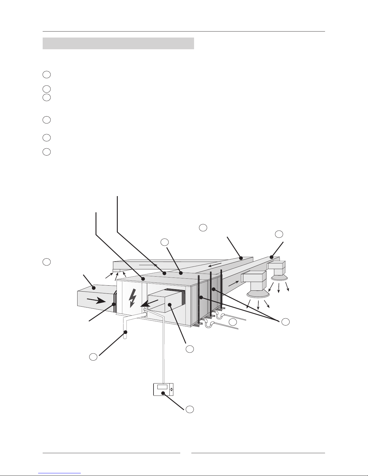
Return air
duct
Supply air duct
Outdoor air
intake duct
Outdoor discharge
duct
Power Supply
Control Panel
Air Filter
Fan access
OUTDOOR SECTION
INDOOR SECTION
Flexible joint
at Openings
FIGURE FOR THE STANDARD UNIT CONFIGURATION FOR MODELS 24-28-30
Trap
Drain
pipe
1
1
2
2
2
2
2
3
3
4
4
5
5
6
6

26
2
2
2
3.- COMMISSIONING AND OPERATION
- On the heat pump units, the compressor has a single phase electric heating element to assure a separation
between the Refrigerant and the oil in the housing. This heater is activated when the compressor is off and stops
working when the compressor is on.
About eight hours before start up or after a long shutdown period, voltage should be supplied to the unit so that
this heater will be activated.
- To start the unit, follow the instructions given in the Control Panel Manual supplied with the unit (requesting
operation in any of the modes, cooling, heating, or automatic).
After a time lapse, the unit will start.
- With unit operating, check that the fans are turning freely and in the proper direction.
3.2.- STEPS TO FOLLOW FOR COMMISSIONING THE UNITS
- Check compressor oil level, if sight glass included (on the sides of the compressor, the level should be between
1/4 and 3/4 in the sight glass, while during operation the level should be between 3/4 and full).
- Connect high and low pressure gauges and check that operating pressure values are normal.
- Measure electrical consumption for the unit and check that it is near what is indicated on the Rating Plate.
- Check the electrical consumption of the compressor and the fans with what is specified in the physical data sheets.
- In the case of a Heat Pump unit, make a cycle change on the Control Panel checking that the 4-way valve makes
the change correctly. Check the pressure values in the new cycle.
- Remember the low pressure switch is reset automatically and the high pressure switch is reset electronically.
- Check that pressure switches stop the unit:
FOR THE COOLING CYCLE UNIT:
Stop the outdoor fan by disconnecting it. The high pressure should rise and the pressure switch should stop the
compressor at 27.5 kg/cm . Reconnect the fan and electrically reset the pressure switch by pressing the RESUME
button on the Control Panel for 5 seconds and wait for the anti-cycle time (5 minutes), afterwards, the unit will
start-up again.
Stop the indoor fan by disconnecting it. The low pressure should drop and the unit should stop when the pressure
gauge reaches 1 kg/cm . The unit will start up again when the pressure rises and the pressure gauge indicates
2 kg/cm . Once this has been carried out, stop the unit and reconnect the fan.
- Start the unit again and when everything is operating normally, take a reading of all the data and fill out the
Commissioning Sheet.
Scroll type compressors only compress in one direction of the rotation. Single phase models are always
started up in the proper direction; however, the three phase models, turn in either direction depending on
the order of the power supply phases. Therefore, it is essential that the phase connection for scroll-type
three-phase compressors be carried out correctly (the correct direction of rotation can be checked when
the pressure on the suction side decreases and the pressure on the discharge side increases when the
compressor is activated. If the connection is wrong, the rotation will be reversed causing a high noise level
and a reduction in the amount of current consumed. If this occurs, the compressors internal protection
system will kick in shutting down the unit. The solution is to disconnect, switch the wires between two of
the phases and connect again).
REMEMBER THAT THE COMPRESSOR IS A SCROLL TYPE COMPRESSOR:

27
4.- MAINTENANCE
-GENERAL STATE OF THE CASING :
Furniture, paint, deterioration due to bumps, rust spots, leveling and supporting, state of the shock absorbers,
if installed, screwed panels, etc.
- ELECTRICAL CONNECTIONS :
State of hoses, tightness of screws, grounding, current draw of the compressor and fans and checking that the
unit is receiving the correct voltage.
- COOLING CIRCUIT :
Check that pressure values are correct and that there are no leaks. Check that there is no damage to the pipe
insulation, that the state of the coils is correct and that there are no chips or clogs retained by the air flow, etc.
- COMPRESSOR :
Inspect the oil level, if sight glass is present.
Inspect the state of the silent block fixtures.
- DRAINS :
Check that water drains correctly and that the drain trays are clean.
- FANS :
Check that fans turn freely and in the correct direction without excesive noises.
- CONTROL :
Check Set Points and normal operation.
- AIR FILTER :
The air filter can be removed through the side by sliding it over the rail or down. (See figure).
For down removal, remove the one or two profiles supporting it (depending on the model) which are under the
filter guide rail and screwed into the unit.
The filter should be cleaned with a vacuum cleaner or washed in soapy water.
The frequency for cleaning or changing the air filters will depend on the quality air in the area (fumes, vapors,
suspended dust particles, etc.).
Remember that the metal grille should be always toward the inside of the unit.
4.1.- PREVENTIVE MAINTENANCE
DOWN
REMOVAL
SIDE
REMOVAL
PREVENTIVE MAINTENANCE PREVENTS COSTLY REPAIRS.
BECAUSE OF THIS PERIODIC INSPECTIONS ARE REQUIRED.
Remember that the Control Panel may program a notification parameter, for cleaning or
replacement of air filters depending on the number of hours of fan operation in the indoor section.

28
4.- MAINTENANCE
If some component in the cooling circuit must be replaced, follow these recommendations:
- Always use original replacement parts.
- Remove the entire refrigerant charge from the unit through the schrader valves located in the outdoor section.
Create a slight vacuum as a safety measure.
- Regulation prohibits the release on the refrigerant into the atmosphere.
- If cuts must be made in the pipe work, use pipe cutters. Do not use saws or any other tools that produce filings.
- All brazing must be carried out in a nitrogen atmosphere to prevent corrosion from forming.
- Use silver alloy brazing rod.
- Take special care that the flame from the torch is aimed in the opposite direction from the component to be
welded and is covered with a wet rag in order to avoid overheating.
- Take very special care if 4-way or check valves are to be replaced since these have internal components that
are very heat-sensitive such as plastic, teflon, etc.
- If a compressor must be replaced, disconnect it electrically and un-braze the suction and discharge lines. Remove
the securing screws and replace the old compressor with the new one. Check that the new compressor has the
correct oil charge, screw it to the base and connect the lines and electrical connections.
- Carry out the vacuum above and below through the schrader valves of the outdoor unit until -750 mm Hg is
reached.
Once this level of vacuum has been reached, keep the pump in operation for at least one hour. DO NOT USE
THE COMPRESSOR AS A VACUUM PUMP.
- Charge the unit with refrigerant according to the data on the Rating Plate for the unit and check that there are
no leaks.
4.2.- CORRECTIVE MAINTENANCE
IMPORTANT
MAKE SURE THAT THE UNIT IS COMPLETELY DISCONNECTED FROM THE POWER SUPPLY
WHEN CARRYING OUT ANY TYPE OF WORK ON THE MACHINE
If R-407C Refrigerant is used in the unit, the following precautions characteristic of this gas should
be taken:
- The Vacuum Pump must have a Check Valve or Solenoid Valve.
- Pressure Gauges and Hoses for the exclusive use with R-407C Refrigerant should be used.
- The charge should be carried out in the Liquid Phase.
- Always use scales to weight-in charge- Use the Leak Detector exclusive for R-407C Refrigerant.
- Do not use mineral oil, only Synthetic oil to ream, expand or make connections.
- Keep pipes closed before using them and be very thorough about any possible dirt (dust, filings,
burrs, etc.).
- When there is a leak, gather what is left of the charge, create a vacuum in the unit and completely
recharge with new R-407C Refrigerant.
- Brazing should always be carried out in a nitrogen atmosphere.
- Reamers should always be well sharpened.
PRECAUTIONS TO BE TAKEN IN THE USE OF R-407C Refrigerant
Direction of the flame
Silver alloy welding rod
Wet rag
Component to be welded
Nitrogen

29
FAILURE
POSSIBLE CAUSES POSSIBLE SOLUTIONS
UNIT DOES NOT START
Failure in the power supply, or
insufficient voltage.
UNIT STOPS DUE TO HIGH
PRESSURE DURING THE
COOLING CYCLE
The same causes and solutions as the Cooling Cycle but with reference to
the coils and Indoor Fan.
UNIT STARTS AND STOPS IN
SHORT CYCLES
Compressor overcharged.
Inspect suction and discharge pressure
values and correct.
UNIT STOPS DUE TO HIGH
PRESSURE DURING THE
HEATING CYCLE
UNIT STOPS DUE TO LOW
PRESSURE
LOAD AND ABNORMAL
NOISE IN THE
COMPRESSOR (SCROLL)
WATER LEAKS
Circuit breakers have opened.
Power cable or Control Panel cable
is defective.
Connect the power supply or check
the voltage.
Reset.
Inspect and Correct.
High Pressure switch is defective.
Outdoor fan is not working.
Outdoor Fan turns in the wrong
direction.
Outdoor Coil is dirty or clogged for
passing air
Check Cut-off Pressure or
change Pressure Switch if necessary.
Check for voltage, inspect the motor and
turbine or replace if necessary.
Switch the power phases.
Inspect and Clean.
Low pressure switch defective.
Check the Cut-off Pressure with a
pressure gauge and change the
Pressure switch if necessary.
Indoor Fan is not working.
Check for voltage and inspect the
motor, turbine and replace if necessary.
Indoor Fan turns in the wrong
direction.
Switch the power phases.
Lack of refrigerant. Leak. Correct leak, create vacuum and charge.
Dirty Air Filter Inspect and Clean.
Clogged Cooling Circuit.
Dirty filter drier.
Compressor cuts off due to Klixon.
Inspect input voltage and voltage drop.
Lack of Refrigerant. Correct leak and replace.
Power supply phases inverted
(three-phase compressor).
Inspect and switch power phases.
Clogged drainage.
Inspect and Clean.
Loose drainage pipe connections.
Correct connection.
Dirty and overflowing trays.
Inspect and Clean.
Inspect and Correct or Change the
Filter drier.
4.- MAINTENANCE
Excess charge of the Refrigerant.
4.3.- FAILURE DIAGNOSIS
In case of failure or malfunction of the unit, the Display on the Control Panel will show an Error or Alarm warning
explained in the Control Panel Manual. Nevertheless, whenever there is an unit failure, the unit should be shut
down and our Service Technicians consulted.
Remove the charge and charge
according to the data on the Rating Plate.

30

COD: MIL60E-0501 03-2005
Due to Lennox's ongoing commitment to quality, Specifications, Ratings and Dimensions subject to change without notice and without incurring liability.
Improper installation, adjustment, alteration, service or maintenance can cause property damage or personal injury.
Installation and service must be performed by a qualified installer and servicing agency.
www.lennoxeurope.com
BELGIUM,
LUXEMBOURG :
CZECH REPUBLIC :
FRANCE :
GERMANY :
IRELAND :
NETHERLANDS :
POLAND :
PORTUGAL :
RUSSIA :
SLOVAKIA :
SPAIN :
UKRAINE :
UNITED KINGDOM :
OTHER COUNTRIES :
LENNOX BENELUX N.V./S.A.
www.lennoxbelgium.com
LENNOX JANKA a.s.
www.janka.cz
LENNOX FRANCE
www.lennoxfrance.com
LENNOX DEUTSCHLAND GmbH
www.lennoxdeutschland.com
LENNOX IRELAND
www.lennoxireland.com
LENNOX BENELUX B.V.
www.lennoxbenelux.com
LENNOX POLSKA Sp. z o. o.
www.lennoxpolska.com
LENNOX PORTUGAL Lda.
www.lennoxportugal.com
LENNOX DISTRIBUTION MOSCOW
www.lennoxrussia.com
LENNOX SLOVENSKO s.r.o.
www.lennoxdistribution.com
LENNOX REFAC S.A.
www.lennox-refac.com
LENNOX DISTRIBUTION KIEV
www.lennoxrussia.com
LENNOX UK
www.lennoxuk.com
LENNOX DISTRIBUTION
www.lennoxdistribution.com
 Loading...