

Page 1
HEARTH PRODUCTS
™
KITS AND ACCESSORIES
775,251M
Rev. A, 09/2008
INSTALLATION INSTRUCTIONS FOR CONVERTING FROM NATURAL GAS (NG) TO
PROPANE GAS (LP). FOR USE WITH THE FIRESTAR™ GC3 B-VENT GAS FIREPLACE INSERT
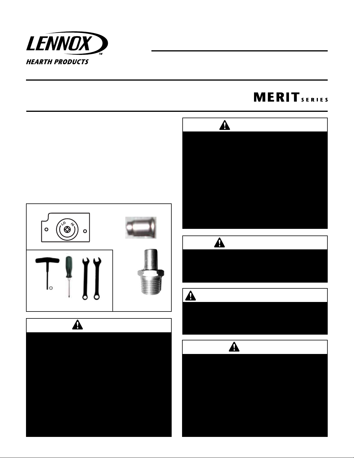
KIT CONTENTS (See Figure 1):
1 ea. Robertshaw LP Regulator Kit (A)
1 ea. Robertshaw LP Pilot Orifice (B)
1 ea. #49 LP main burner orifice (39,000 BTU’s) (C)
1 ea. Instruction Sheet
FIRESTAR™ GAS CONVERSION INSTRUCTIONS NG TO LP
CAT. NO. 75173, MODEL FSTR-CK-NG TO LP
AVERTISSEMENT
Cet équipement de conversion sera installé par une
agence qualifiée de service conformément aux instructions du fabricant et toutes exigences et codes applica-
TOOLS NEEDED (See Figure 2):
bles de l'autorisés avoir la juridiction. Si l'information
dans cette instruction n'est pas suivie exactement, un
5/32” Long Allen Wrench Or T-Handle Wrench
#2 Phillips Screwdriver
7/16” Open End Wrench
3/4” Open End Wrench
feu, explosion ou production de protoxyde de carbone
peut résulter le dommages causer de propriété, perte
ou blessure personnelle de vie. L'agence qualifiée de
service est esponsable de l'installation propre de cet
équipment. L'installation n'est pas propre et compléte
jusqu'à l'opération de l'appareil converti est chéque
suivant les critères établis dans les instructions de
A
B
propriétaire provisionnées avec l'équipement.
C
Fig. 2
Figure 2 - Tools Needed
WARNING
Figure 1 - Kit Contents
This conversion kit shall be installed by a qualified
service agency in accordance with the manufacturer's
instructions and all applicable codes and requirements
of the authority having jurisdiction. If the information
in these instructions is not followed exactly, a fire,
explosion or production of carbon monoxide may result
causing property damage, personal injury or loss of
life. The qualified service agency performing this
installation is responsible for the proper installation
of this kit and assumes responsibility for this conversion. The installation is not proper and complete until
the operation of the converted appliance is checked as
specified in the manufacturers instructions supplied
with the kit.
IMPORTANT CANADA
The conversion shall be carried out in accordance with
the requirements of the provincial authorities having
jurisdiction and in accordance with the requirements
of the CAN/CSA B149.1 Installation code.
IMPORTANT LE CANADA SEULEMENT
La conversion devra être effectuée conformément
aux recommandations des autorités provinciales
ayant juridiction et conformément aux exigences
du code d'installation CAN/CSA B149.1 .
IMPORTANT
The burner orifices provided in this kit are only for
use at elevations of 0 to 2,000 feet (610 M) in the
USA and 0 to 4,500 feet (0-1372 M) in Canada. At
higher elevations the BTU input must be de-rated
by 4% for every 1,000 feet (305 M) to maintain
the proper ratio of gas to air. If the installer must
convert the unit to adjust for varying altitudes, a
deration information sticker must be filled out by the
installer and adhered to the appliance at the time
of the conversion. Contact your local gas supplier
for deration requirements for your area.
1
Page 2
READ ALL THE STEPS BEFORE STARTING THE CONVERSION.
LO
HI
INSTALLER NOTICE: THESE INSTRUCTIONS MUST BE LEFT WITH
THE APPLIANCE.
This kit contains components required to convert this appliance
from using Natural Gas to using Propane Gas as the only fuel.
All of these components must be replaced in order for the unit to
operate safely on Propane Gas.
When installing gas components use pipe joint compound or
Teflon tape on all pipe fittings before installing (ensure propane
resistant compounds are used, do not use pipe joint compounds
on flare fittings).
INSTALLATION INSTRUCTIONS
Step 1. TURN OFF THE GAS SUPPLY TO THE APPLIANCE. Unplug the
power cord for the blower.
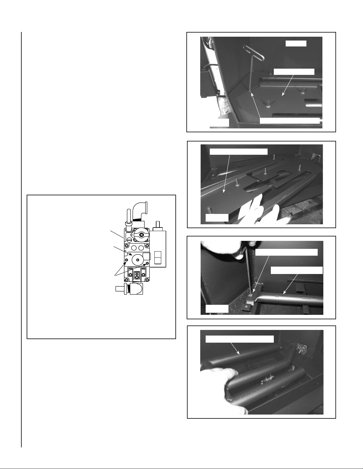
Step 2. Locate the valve behind the right side access door. Using a phil-
lips screwdriver, remove and discard the two pressure regulator
mounting screws (see Figure 3). Remove the pressure regulator
and rubber gasket. Discard all removed components. Install
the new regulator. Ensure the rubber gasket on the back of the
pressure regulator is properly positioned when installing the new
pressure regulator using the new screws supplied with this kit.
Locate the label provided in the regulator kit. Write in the required
information, then affix it to the valve.
Figure 4
Lift Out Air Control Panel
Firebox
Air Control Panel
Remove Allen-Head Screw
Gas Valve
(located in control compartment below firebox)
1. Replace Regulator.
2. Fill out & affix label
from regulator kit to
valve
IMPORTANT NOTE: Do not overtighten the regulator screws.
Overtightened screws may result in little to no difference in
flame height when adjusted from high to low.
Regulator
Remove These
Screws
Figure 3 - Replace Regulator on Valve
Step 3. Remove the glass door by opening both latches on the right and
left side of the door (see Page 18 in the Installation and Operation
Manual). Carefully remove the logs. Exercise care so as not to
break the logs. Set aside in a safe place.
Step 4. Using a 5/32” allen wrench, remove the allen-head screw on the
left side of the air control panel as shown in Figure 4, then lift
out air control panel as shown in Figure 5.
Figure 5
Remove Allen-Head Screw
Burner Tube Assembly
Figure 6
Lift Out Burner Tube Assembly
Step 5. Using a 5/32” allen wrench, remove the screw which secures
burner tube assembly as shown in Figure 6. Then lift out burner
tube assembly as shown in Figure 7.
2
NOTE: DIAGRAMS AND ILLUSTRATIONS ARE NOT TO SCALE.
Figure 7
Page 3

Step 6. Using a 7/16” open-end wrench, remove the pilot orifice by loosening
LO
HI
the nut (see Figure 5) on the end of the pilot supply tube. Once the
nut is removed, slide the nut down the tube, then pull the supply
tube down no more than 1/2” out of the fitting and orifice will fall
out. Once the orifice is out, discard it and put the new one in, then
reinstall the nut.
Pilot Assembly
Pilot Tube Nut
Figure 8
Step 8. Adjust the air shutter as follows (see Page 12 in the Installation
and Operation Manual); The main burner has an adjustable air
shutter located at the end of the burner (see Figures 10 and 11).
Using a phillips screwdriver, loosen the air shutter setscrew just
enough so the air shutter can be rotated by hand (See Figures 10
and 11).
The setscrew for the air shutter is secured tightly from the factory
so that it does not rotate from the factory setting during shipping.
Once you loosen the setscrew just enough so that it can be rotated
by hand, then reinstall the burner tube, you will be able to access
and adjust the air shutter from behind the right side panel to a
100% open gap for propane gas (below valve).
After step 12, with the appliance lit and fully warmed up, evaluate
the burner flame appearance and re-adjust air shutter for proper
flame appearance, if necessary.
Step 7. Using a 3/4” open-end wrench, remove burner orifice. Replace
with #49 LP orifice that is supplied in this kit. Make sure to use
pipe sealing compound on threads of new orifice (see Figure 9).
Gas Valve
Burner Orifice
Figure 9 - Replace Burner Orifice
Setscrew
Air Shutter
Figure 10
Figure 11
NOTE: DIAGRAMS AND ILLUSTRATIONS ARE NOT TO SCALE.
Air Shutter
3
Page 4

Step 9. Turn on gas supply and test for gas leaks using a gas leak test
solution (see Test Procedure on Page 11 in the Installation and
Operation Manual).
Step 10. Using a manometer, test the inlet and manifold gas pressure per
instructions in the Installation and Operation Manual (Page 11)
and as shown in the following 2 tables.
Millivolt Pilot
Gas Pilot Hood
3/8” to
1/2”
Inlet Gas Supply Pressure
Fuel # Minimum Maximum Desired
LP
10.5" WC/po. C.E
(2.62 kPa)
13.0" WC/po. C.E
(3.23 kPa)
11" WC/po. C.E
(2.74 kPa)
Manifold Gas Supply Pressure
Fuel # Low High
LP
(Lo) 5.4" WC/po. C.E
(1.35 kPa)
(Hi) 10.0" WC/po. C.E
(2.49 kPa)
Step 11. Reinstall the the log set and glass door assembly. See Pages
9 and 10 (Log Set Installation) and Page 18 (Door Assembly
Installation) in the Installation and Operation Manual.
Step 12. Light the appliance per the lighting instructions label on appliance
(when viewing the insert from the front, it is located behind the
right side door, on the right) or lighting instructions on Page 13
in the Installation and Operation Manual. Inspect for proper pilot
and burner flame appearances. See Flame Color and Behavior
on Page 14 and Inspect The Pilot System For Proper Flame on
Page 16 in the Installation and Operation Manual. Also see
Figures 12 and 13.
Igniter
Figure 12 - Proper Pilot Flame Appearance
Soot at
Flame Tip
Dark Orange
Flame
No Blue Flame
Center
IMPROPERLY
BURNING FLAME
Soot above
Flame Tip
Ports on Pan
Burner Assembly
PROPERLY
BURNING FLAME
Figure 13 - Burner Flame Appearance
Thermopile
No Soot at
Flame Tip
Semi-Transparent
Yellow Flame
Blue Flame
Center
Lennox Hearth Products reserves the right to make changes at any time, without notice, in
design, materials, specifications, prices and also to discontinue colors, styles and products.
Consult your local distributor for fireplace code information.
Printed in U.S.A. © 2008 Lennox Hearth Products
P/N 775,251M REV. A 09/2008
4
1110 West Taft Avenue • Orange, CA 92865
 Loading...