

Lennox FCA 120, FCA 140, FCA 160, FCA 190, FCK 60 Installation, Operation And Maintenance Manual
...
INSTALLATION
OPERATING &
MAINTENANCE MANUAL
ROOFTOP
FLEXY™
English
August 2003

IOM / ROOF-TOP FLEXY™ Series - Page 1
CONTENTS
The present manual applies to the following ROOFTOP versions :
FCA 60 - FCA 70 - FCA 85 - FCA 100 - FCA 120 - FCA 140 - FCA 160 - FCA 190
FCK 60 - FCK 70 - FCK 85 - FCK 100 - FCK 120 - FCK 140 - FCK 160 - FCK 190
FHA 60 - FHA 70 - FHA 85 - FHA 100 - FHA 120 - FHA 140 - FHA 160 - FHA 190
FHK 60 - FHK 70 - FHK 85 - FHK 100 - FHK 120 - FHK 140 - FHK 160 - FHK 190
FDA 60 - FDA 70 - FDA 85 - FDA 100 - FDA 120 - FDA 140 - FDA 160 - FDA 190
FDK 60 - FDK 70 - FDK 85 - FDK 100 - FDK 120 - FDK 140 - FDK 160 - FDK 190
FGA 60 - FGA 70 - FGA 85 - FGA 100 - FGA 120 - FGA 140 - FGA 160 - FGA 190
FGK 60 - FGK 70 - FGK 85 - FGK 100 - FGK 120 - FGK 140 - FGK 160 - FGK 190
FXA 25 - FXA 30 - FXA 35 - FXA 40 - FXA 55 - FXA 70 - FXA 85 - FXA 100 - FXA 1 10 - FXA 140 - FXA 170
FXK 25 - FXK 30 - FXK 35 - FXK 40 - FXK 55 - FXK 70 - FXK 85 - FXK 100 - FXK 110 - FXK 140 - FXK 170
The technical information and specifications contained in this manual are for reference only. The manufacturer reserves the right to modify these without
warning and without obligation to modify equipment already sold.
Ref. FLEXY_IOM/0803-E
NOTES FOR UNIT FITTED WITH GAS BURNER :
THE UNIT MUST BE INSTALLED IN ACCORDANCE WITH LOCAL
SAFETY CODES AND REGULATIONS AND CAN ONLY BE USED IN
WELL VENTILLATED AREA.
PLEASE READ CAREFULLY THE MANUFACTURER'S INSTRUCTIONS
BEFORE STARTING THIS UNIT.
THIS MANUAL IS ONLY VALID FOR UNITS DISPLAYING THE
FOLLOWING CODES:
GB IR GR DA NO FI IS
In case these symbols are not displayed on the unit, please refer to the
technical documentation which will eventually detail any modifications
required to the installation of the unit in a particular country.
INSTALLATION
OPERATION
MAINTENANCE MANUAL

Page 2 - IOM / ROOF-TOP FLEXY™ Series
CONTENTS
IMPORT ANT NOTICE......................................................................................... 3
INSTALLATION
TRANSPORT - HANDLING .............................................................................................. 4
INSTALLATION ............................................................................................................... 12
INST ALLATION ON A ROOF MOUNTING FRAME...........................................................13
INSTALLA TION ON POSTS ............................................................................................ 15
COMMISSIONING........................................................................................................... 16
OPERATION
VENTILATION ................................................................................................................. 21
AIR FLOW BALANCING.................................................................................................. 23
FILTERS .........................................................................................................................39
FANST ART OPERA TION................................................................................................. 40
FX AIR FLOW BALANCING............................................................................................. 41
HOT WA TER COILS ....................................................................................................... 44
GAS BURNERS.............................................................................................................. 45
CONTROL FUNCTIONS
USING THE KP 17 COMFORT DISPLA Y........................................................................ 57
USING THE KP02 MAINTENANCE DISPLAY................................................................. 58
USING THE KP07 REMOTE GRAPHICAL DISPLA Y...................................................... 72
BMS CONTACTS KIT...................................................................................................... 81
CLIMATIC™ P ARAMETERS............................................................................................82
CONTROL INTERF ACE CLIMALINK/CLIMALOOK......................................................... 88
WIRING DIAGRAMS
ELECTRICAL WIRING DIAGRAMS LIST OF ITEMS....................................................... 96
ELECTRICAL WIRING DIAGRAMS .............................................................................. 100
TROUBLESHOOTING
SAFETY AND ERROR CODES..................................................................................... 117
MAINTENANCE DIAGNOSTIC .....................................................................................123
MAINTENANCE PLAN ..................................................................................................126
WARRANTY ..................................................................................................................129
CERTIFICATES
ISO 9001 CERTIFICA TION........................................................................................... 130
PED CERTIFICA TION OF CONFORMITY..................................................................... 131
GLAS WOOL FIRE CLASS ........................................................................................... 132
33 KW GAS BURNER CE CERTIFICA TION OF CONFORMITY................................... 133
60 KW GAS BURNER CE CERTIFICA TION OF CONFORMITY................................... 134
120 KW GAS BURNER CE CERTIFICA TION OF CONFORMITY................................. 135
180 kW GAS BURNER CE CERTIFICA TION OF CONFORMITY ................................. 136
INSULATION FIRE CLASS ........................................................................................... 137
CONTENTS

IOM / ROOF-TOP FLEXY™ Series - Page 3
IMPORTANT NOTICE
IMPORTANT NOTICE
All work on the unit must be carried out by a qualified and authorised employee.
Non-compliance with the following instructions may result in injury or serious accidents.
Work on the unit:
• The unit shall be isolated from the electrical supply by disconnection and locking using the
main isolating switch.
• Workers shall wear the appropriate personal protective equipment (helmet, gloves,
glasses, etc.).
Work on the electrical system:
• Work on electric components shall be performed with the power off (see below) by
employees having valid electrical qualification and authorisation.
Work on the refrigerating circuit(s):
• Monitoring of the pressures, draining and filling of the system under pressure shall be
carried out using connections provided for this purpose and suitable equipment.
• To prevent the risk of explosion due to spraying of coolant and oil, the relevant circuit shall
be drained and at zero pressure before any disassembly or unbrazing of the refrigerating
parts takes place.
• There is a residual risk of pressure build-up by degassing the oil or by heating the
exchangers after the circuit has been drained. Zero pressure shall be maintained by
venting the drain connection to the atmosphere on the low pressure side.
• The brazing shall be carried out by a qualified brazier. The brazing shall comply with standard NF EN1044 (minimum 30% silver).
Replacing components:
• In order to maintain CE marking compliance, replacement of components shall be carried
out using spare parts, or using parts approved by Lennox.
• Only the coolant shown on the manufacturer's nameplate shall be used, to the exclusion of
all other products (mix of coolants, hydrocarbons, etc.).
CAUTION:
In the event of fire, refrigerating circuits can cause an explosion and spray coolant gas and oil.
Page 4 - IOM / ROOF-TOP FLEXY™ Series
TRANSPORT - HANDLING
Figure 1
DELIVERY CHECKS
On receipt of a new equipment please check the following
points. It is the customer's responsibility to ensure that the
products are in good working order:
- The exterior has not been damaged in any way.
- The lifting and handling equipment are suitable for the
equipment and comply with the specifications of the handling
instructions enclosed here-in.
- Accessories ordered for on site installation have been
delivered and are in good working order.
- The equipment supplied corresponds to the order and
matches the delivery note.
If the product is damaged, exact details must be confirmed
in writing by registered post to the shipping company within
48 hours of delivery (working days). A copy of the letter must
be addressed to Lennox and the supplier or distributor for
information purposes. Failure to comply will invalidate any
claim against the shipping company.
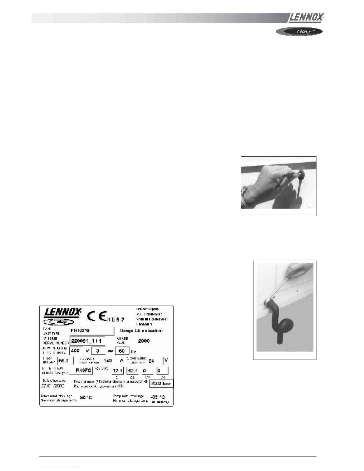
RATING PLATE
The rating plate provides a complete reference for the model
and ensures that the unit corresponds to the model ordered.
It states the electrical power consumption of the unit on startup, its rated power and its supply voltage. The supply voltage
must not deviate beyond +10/-15 %. The start-up power is
the maximum value likely to be achieved for the specified
operational voltage. The customer must have a suitable
electrical supply. It is therefore important to check whether
the supply voltage stated on the unit's rating plate is
compatible with that of the mains electrical supply. The rating
plate also states the year of manufacture as well as the type
of refrigerant used and the required charge for each
compressor circuit.
STORAGE
When units are delivered on site they are not always required
immediately and are sometimes put into storage. In the event
of medium to long-term storage, we recommend the following
procedures :
- Ensure that there is no water in the hydraulic systems.
- Keep the heat exchanger covers in position (AQUILUX cover).
- Keep protective plastic film in position.
- Ensure the electrical panels are closed.
- Keep all items and options supplied in a dry and clean
place for future assembly before using the equipment.
MAINTENANCE KEY
On delivery we recommend that you keep the key which is
attached to an eyebolt in a safe and accessible place. This
allows you to open the panels for maintenance and
installation work.
The locks are ¼ turn +
then tighter (figure 2).
CONDENSATE DRAINS
The condensate drains are not assembled when delivered
and are stored
in the electrical panel with their clamping collars.
To assemble them, insert them
on the condensate tray outlets
and use a screwdriver to
tighten the collars (figure 3).
Figure 3
Figure 2
IOM / ROOF-TOP FLEXY™ Series - Page 5
TRANSPORT - HANDLING
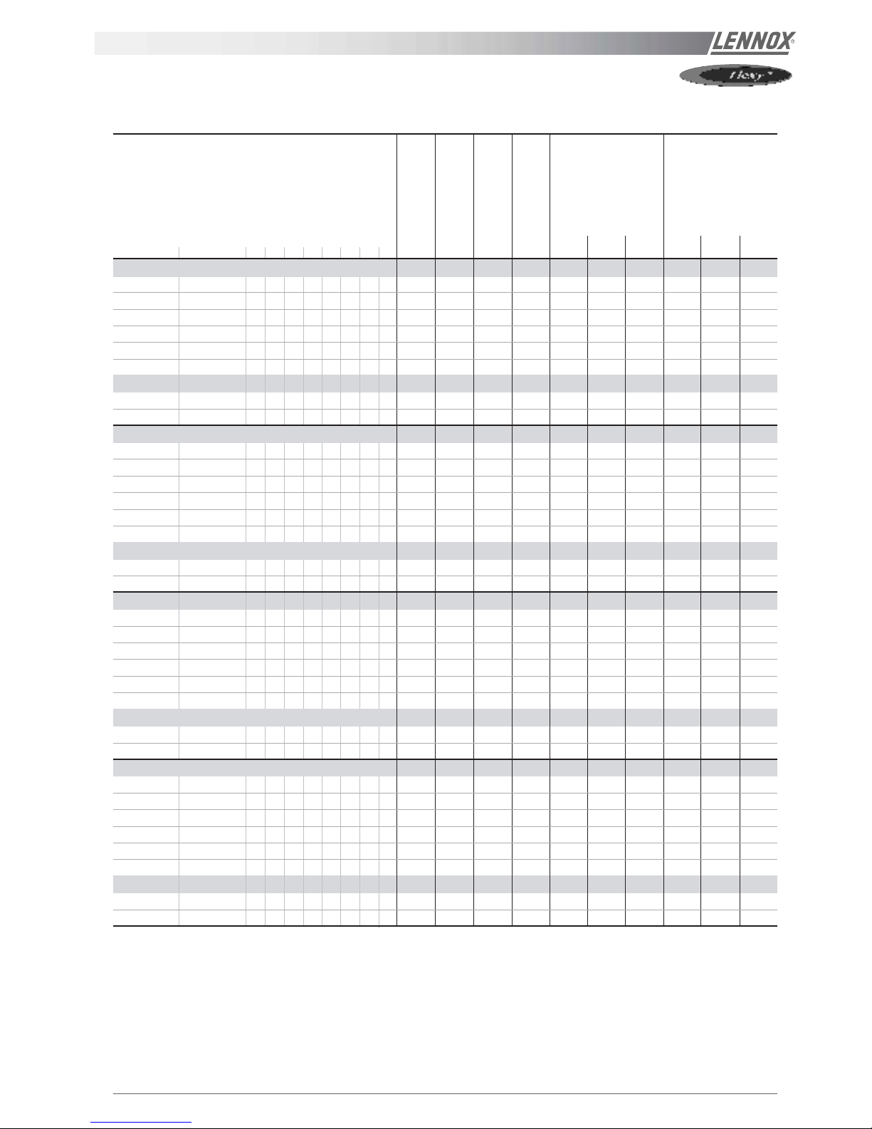
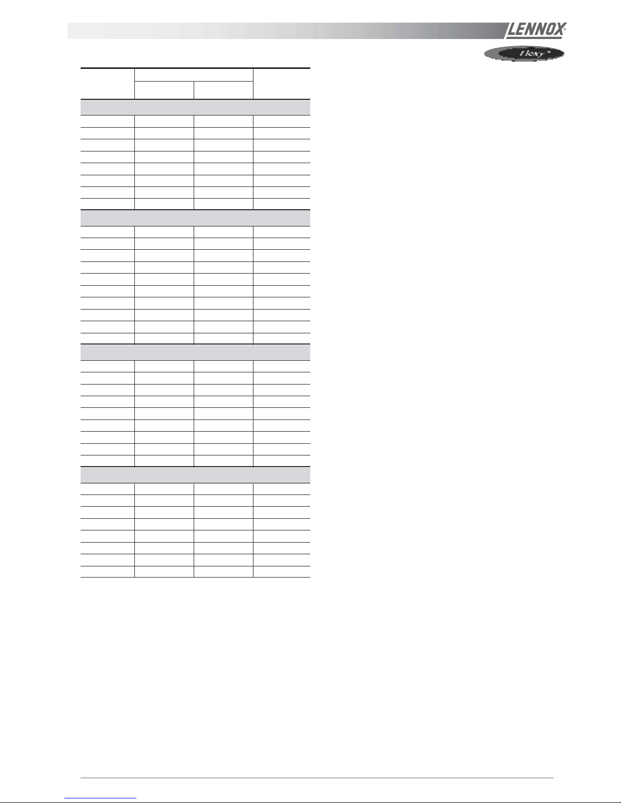
DIMENSIONS AND WEIGHTS
Condensation
Airflow configuration
WEIGHT (kg) SLING
std std high
Standard Centrifugal 12345678 gas gas 1 2 3
FC/FH 060 - Cooling only and heat pump
X - X------X2825 2255 1470 630 1060 - - 2210 - X - - - - X - - X - 2825 2255 1470 630 1090 - - 2210 - X - - X X - X X - - 2825 2285 1470 630 1090 - - 2210 - -
- X X------X2875 2255 2070 630 1230 - - 2590 1855 -
- X - - - X - - X - 2875 2255 2070 630 1260 - - 2590 1855 -
- X - X X - X X - - 2875 2285 2070 630 1260 - - 2590 1855 -
FG 060 - GAS
X - X------X2825 2255 1470 630 - 1210 1280 2210 - -
- X X------X2875 2255 2070 630 - 1380 1450 2590 1855 -
FC/FH 070 - Cooling only and heat pump
X - X------X2825 2255 1470 630 1075 - - 2210 - X - - - - X - - X - 2825 2255 1470 630 1100 - - 2210 - X - - X X - X X - - 2825 2285 1470 630 1100 - - 2210 - -
- X X------X2875 2255 2070 630 1245 - - 2590 1855 -
- X - - - X - - X - 2875 2255 2070 630 1270 - - 2590 1855 -
- X - X X - X X - - 2875 2285 2070 630 1270 - - 2590 1855 -
FC/FH 070 - GAS
X - X------X2825 2255 1470 630 - 1230 1300 2210 - -
- X X------X2875 2255 2070 630 - 1400 1470 2590 1855 -
FC/FH 085 - Cooling only and heat pump
X - X------X3785 2255 1495 630 1220 - - 2830 2330 X - - - - X - - X - 3785 2255 1495 630 1270 - - 2830 2330 X - - X X - X X - - 3785 2285 1495 630 1275 - - 2830 2330 -
- X X------X3835 2255 2080 630 1435 - - 3230 2430 1870
- X - - - X - - X - 3835 2255 2080 630 1485 - - 3230 2430 1870
- X - X X - X X - - 3835 2285 2080 630 1490 - - 3230 2430 1870
FC/FH 085 - GAS
X - X------X3785 2255 1495 630 - 1320 1390 2830 2330 -
- X X------X3835 2255 2080 630 - 1535 1605 3230 2430 1870
FC/FH 100 - Cooling only and heat pump
X - X------X3785 2255 1495 630 1280 - - 2830 2330 X - - - - X - - X - 3785 2255 1495 630 1320 - - 2830 2330 X - - X X - X X - - 3785 2285 1495 630 1320 - - 2830 2330 -
- X X------X3835 2255 2080 630 1495 - - 3230 2430 1870
- X - - - X - - X - 3835 2255 2080 630 1545 - - 3230 2430 1870
- X - X X - X X - - 3835 2285 2080 630 1545 - - 3230 2430 1870
FC/FH 100 - GAS
X - X------X3785 2255 1495 630 - 1380 1450 2830 2330 -
- X X------X3835 2255 2080 630 - 1595 1665 3230 2430 1870
HEIGHT (mm)
HOOD (mm)
WIDTH (mm)
LENGTH (mm)
Page 6 - IOM / ROOF-TOP FLEXY™ Series
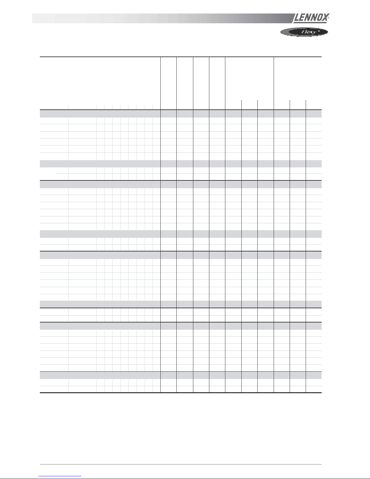
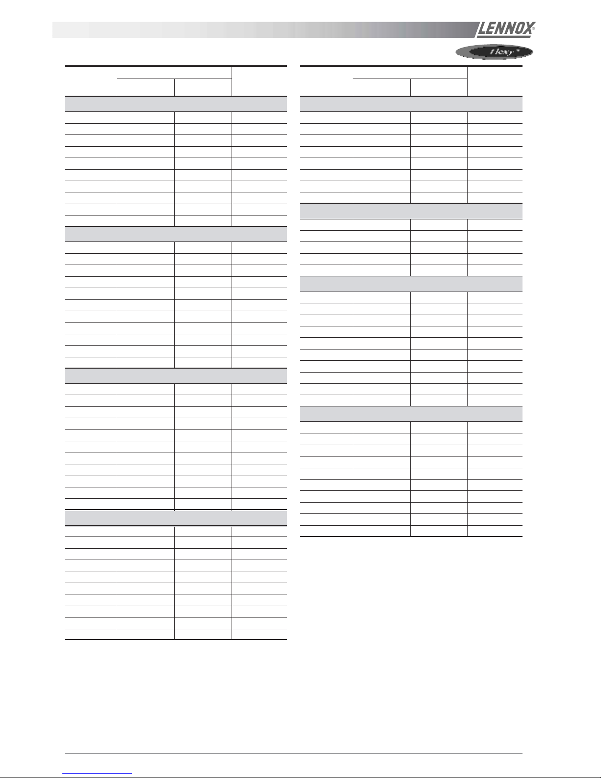
TRANSPORT - HANDLING
DIMENSIONS AND WEIGHTS
WEIGHT (kg) SLING
std std high
Standard Centrifugal 12345678 gas gas 1 2 3
FC/FH 120 - Cooling only and heat pump
X - X------X3585 2255 1470 630 1530 - - 2700 - 2080
X - - - - X - - X - 3585 2255 1470 630 1580 - - 2700 - 2080
X - - X X - X X - - 3585 2285 1470 630 1600 - - 2700 - 2080
- X X------X3635 2255 1930 630 1805 - - 3000 2410 1880
- X - - - X - - X - 3635 2255 1930 630 1855 - - 3000 2410 1880
- X - X X - X X - - 3635 2285 1930 630 1875 - - 3000 2410 1880
FG 120 - GAS
X - X------X4035 2255 1470 630 - 1840 1890 3000 - 2310
- X X------X4085 2255 1930 630 - 2115 2165 3300 2700 2080
FC/FH 140 - Cooling only and heat pump
X - X------X3585 2255 1470 630 1630 - - 2700 - 2080
X - - - - X - - X - 3585 2255 1470 630 1680 - - 2700 - 2080
X - - X X - X X - - 3585 2285 1470 630 1700 - - 2700 - 2080
- X X------X3635 2255 1930 630 1905 - - 3000 2410 1880
- X - - - X - - X - 3635 2255 1930 630 1955 - - 3000 2410 1880
- X - X X - X X - - 3635 2285 1930 630 1975 - - 3000 2410 1880
FG 140 - GAS
X - X------X4035 2255 1470 630 - 1920 1970 3000 - 2310
- X X------X4085 2255 1930 630 - 2000 2050 3300 2700 2080
FC/FH 160 - Cooling only and heat pump
X - X------X3595 2255 2070 900 2050 - - 2700 - 2090
X - - - - X - - X - 3595 2255 2070 900 2120 - - 2700 - 2090
X - - X X - X X - - 3595 2285 2070 900 2140 - - 2700 - 2090
- X X------X3645 2255 2070 900 2275 - - 2700 - 2090
- X - - - X - - X - 3645 2255 2070 900 2345 - - 2700 - 2090
- X - X X - X X - - 3645 2285 2070 900 2365 - - 2700 - 2090
FG 160 - GAS
X - X------X4045 2255 2070 900 - 2410 2460 3000 - 2320
- X X------X4095 2255 2070 900 - 2635 2685 3000 - 2320
FC/FH 190 - Cooling only and heat pump
X - X------X3595 2255 2070 900 2175 - - 2700 - 2090
X - - - - X - - X - 3595 2255 2070 900 2245 - - 2700 - 2090
X - - X X - X X - - 3595 2285 2070 900 2265 - - 2700 - 2090
- X X------X3645 2255 2070 900 2400 - - 2700 - 2090
- X - - - X - - X - 3645 2255 2070 900 2470 - - 2700 - 2090
- X - X X - X X - - 3645 2285 2070 900 2490 - - 2700 - 2090
FG 190 - GAS
X - X------X4045 2255 2070 900 - 2540 2600 3000 - 2320
- X X------X4095 2255 2070 900 - 2765 2825 3000 - 2320
HEIGHT (mm)
CASQUETTE (mm)
Condensation
Airflow configuration
WIDTH (mm)
LENGTH (mm)
IOM / ROOF-TOP FLEXY™ Series - Page 7
TRANSPORT - HANDLING
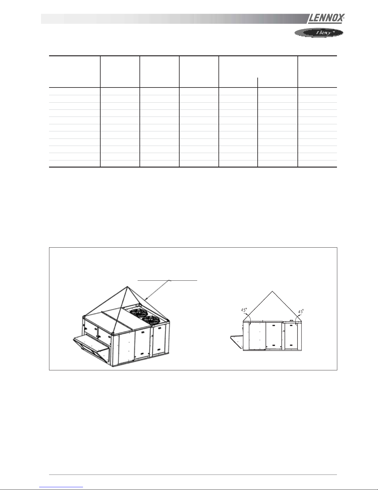
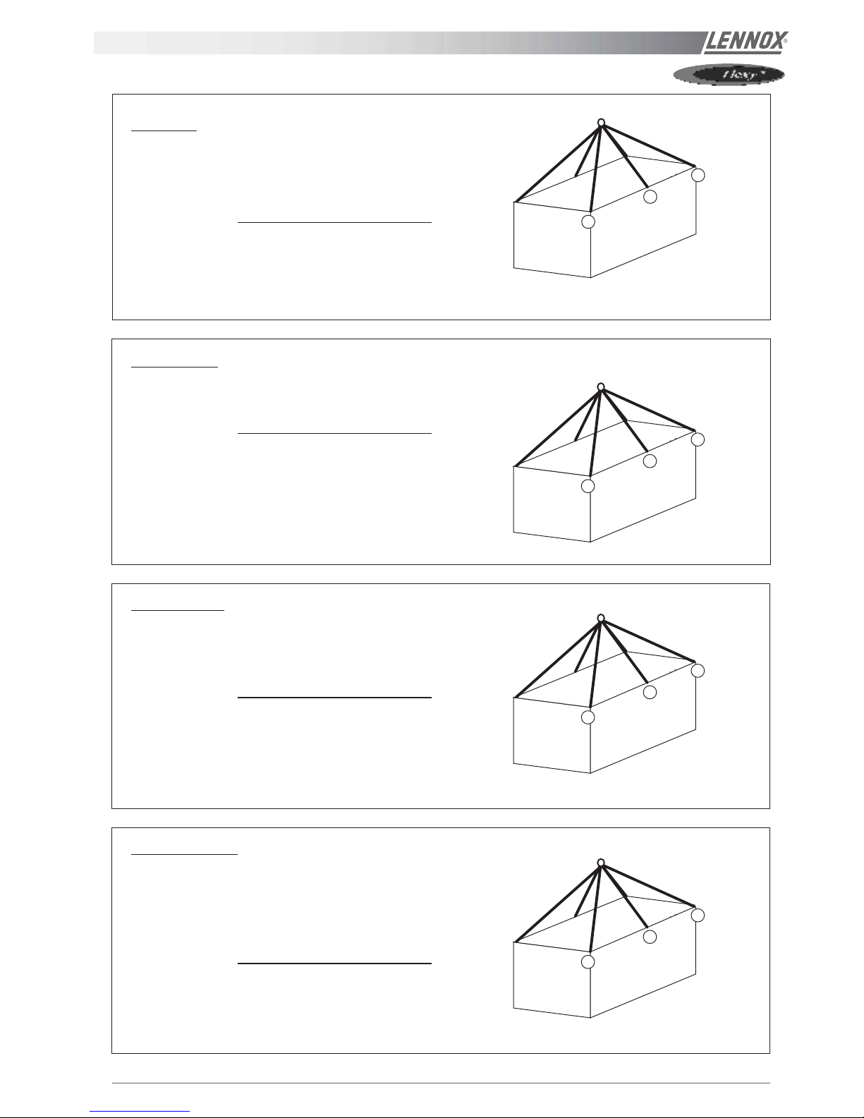
HANDLING
The equipment can be moved using the lifting holes on the
top of the unit.
The "sling" length is the value that we recommend for safe
handling of the equipment.
Some units can only be supported by four slings at rightangles. Others require different lengths (see figures 4).
It is essential that all lifting holes are used and that the slings
are all of the same size to avoid damaging the equipment.
Sling length = 2210 mm
for angle = 45°C
FC.../FH.../FD.../FG... 060 & 070
LENGTH HEIGHT WIDTH AUVENT WEIGHT (kg)
lateral ventil standard
MODELS mm mm mm mm mm kg
FX 025 4070 1635 1055 490 600 950
FX 030 4070 1635 1055 490 600 980
FX 035 4750 2255 1290 490 600 1400
FX 040 4750 2255 1290 490 600 1450
FX 055 4750 2255 1290 490 600 1600
FX 070 5050 2255 1725 890 600 1800
FX 085 5050 2255 1725 890 600 1900
FX 100 5050 2255 1725 890 600 2000
FX 110 5650 2255 2000 860 - 2620
FX 140 5650 2255 2000 860 - 2620
FX 170 5650 2255 2000 860 - 2650
DIMENSIONS AND WEIGHTS
Figure 4 for all handling
drawings - pages 7 to11
Page 8 - IOM / ROOF-TOP FLEXY™ Series
TRANSPORT - HANDLING
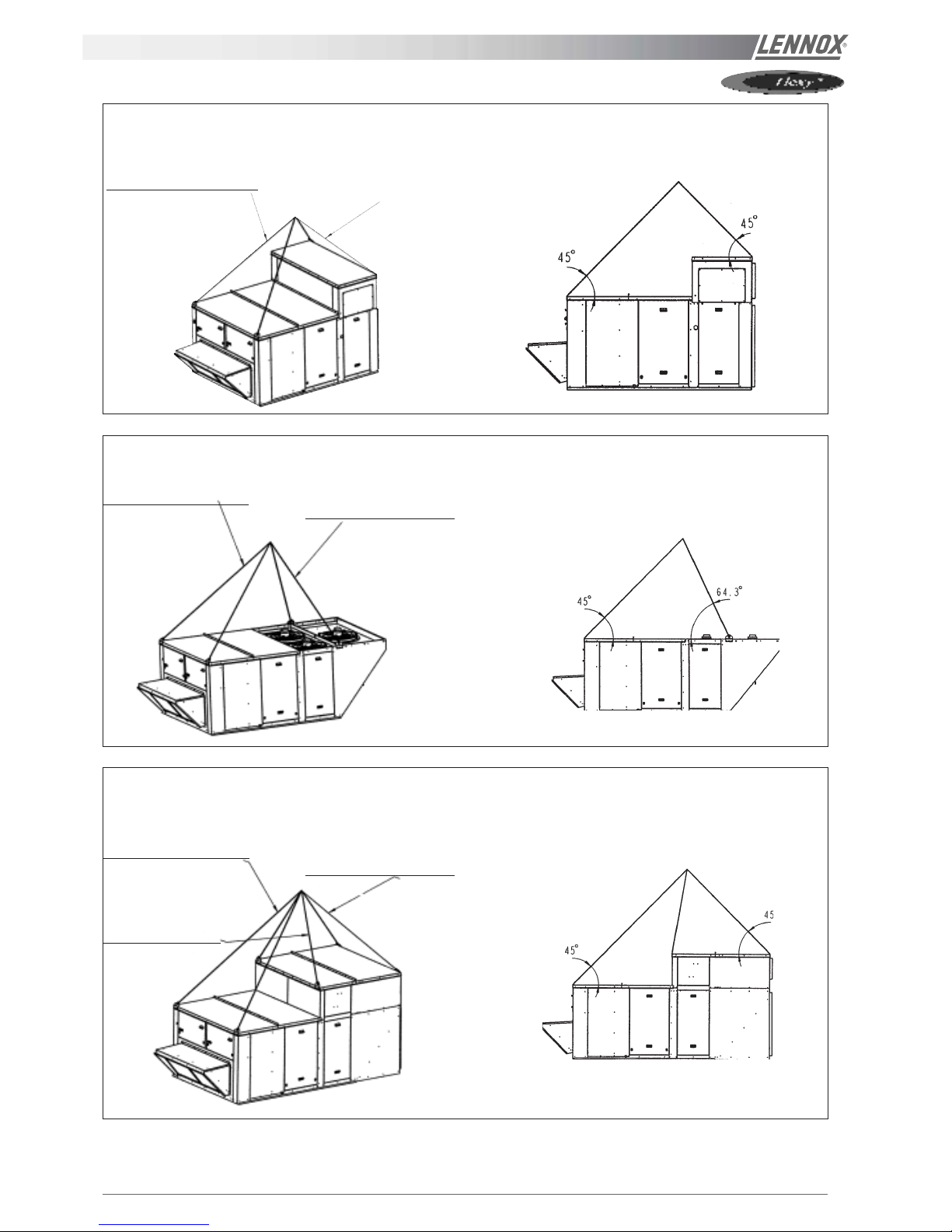
FC.../FH.../FD.../FG... 060 & 070 with centrifugal fans
Sling length = 2590 mm
for angle = 45°C
Sling length = 2330 mm
for angle = 64,5°C
FC.../FH.../FD.../FG... 085 & 100
Sling length = 2430 mm
for angle = 45°C
FC.../FH.../FD.../FG... 085 & 100 with centrifugal fans
Sling length = 3230 mm
for angle = 45°C
Sling length = 2830 mm
for angle = 45°C
Sling length = 1870
mm
for angle = 45°C
Figure 3 for all handling drawings - pages 7 to11
IOM / ROOF-TOP FLEXY™ Series - Page 9
TRANSPORT - HANDLING
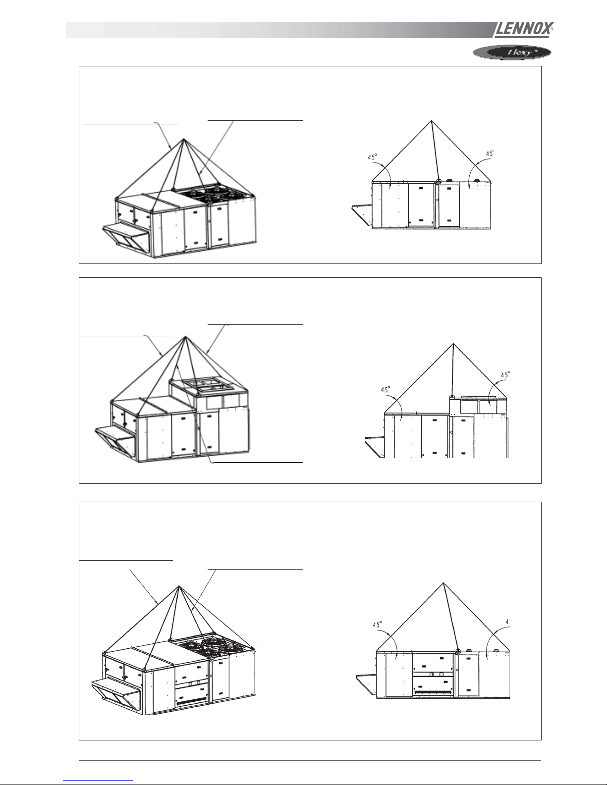
Sling length = 2080 mm
for angle = 45°C
FC.../FH.../FD... 120 & 140
Sling length = 2700 mm
for angle = 45°C
Sling length = 2410 mm
for angle = 45°C
FC.../FH.../FD... 120 & 140 with centrifugal fans
Sling length = 2080 mm
for angle = 45°C
FG... 120 & 140 with gas burner
Sling length = 2700 mm
for angle = 45°C
Sling length = 3000 mm
for angle = 45°C
Sling length = 1880 mm
for angle = 45°C
Figure 3 for all handling drawings - pages 7 to11
Page 10 - IOM / ROOF-TOP FLEXY™ Series
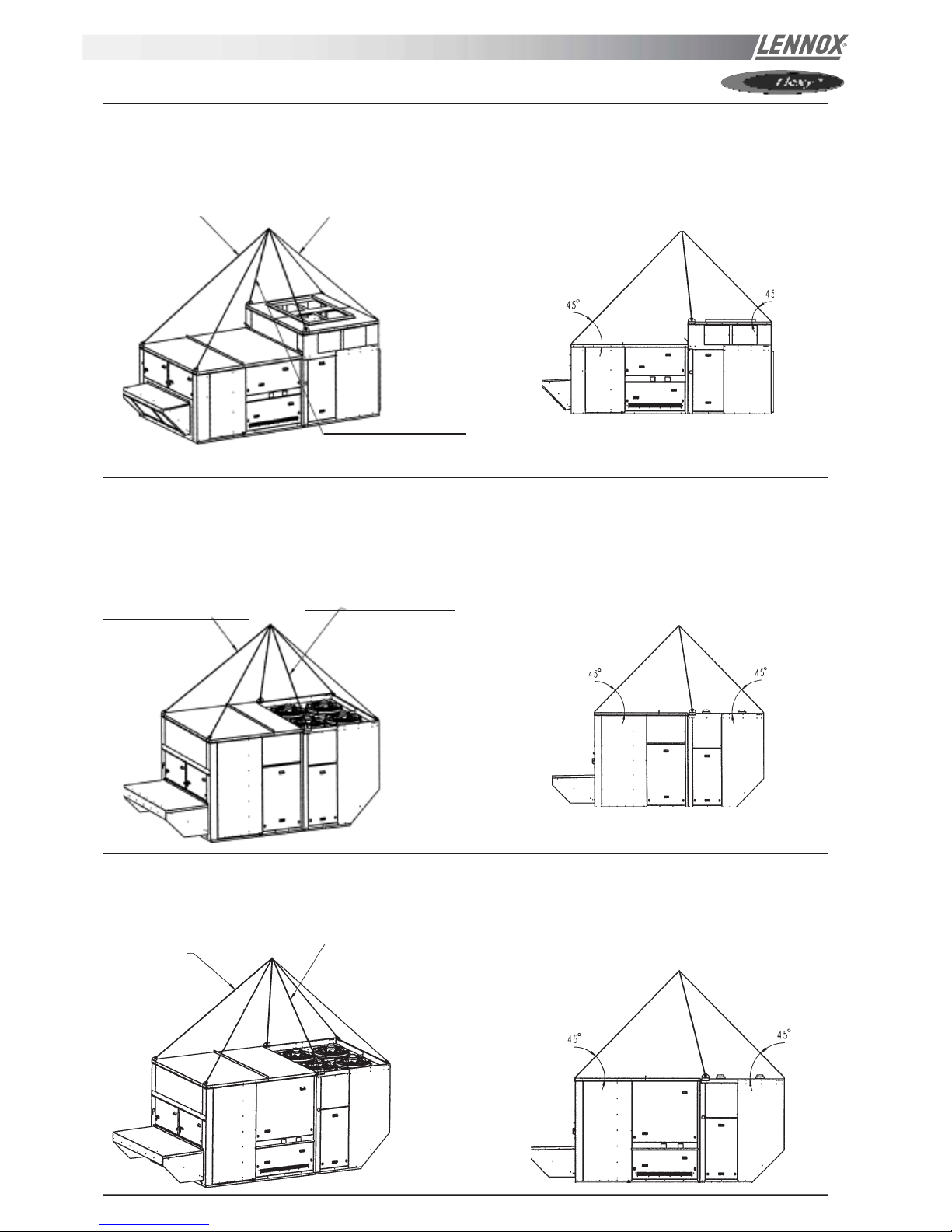
TRANSPORT - HANDLING
Sling length = 2700 mm
for angle = 45°C
FG... 120 & 140 with gas burner and centrifugal fans
Sling length = 3300 mm
for angle = 45°C
Sling length = 2080 mm
for angle = 45°C
Sling length = 2090 mm
for angle = 45°C
FC.../FH.../FD... 160 & 190
FC.../FH.../FD... 160 & 190 with centrifugal fans
Sling length = 2700 mm
for angle = 45°C
Sling length = 2320 mm
for angle = 45°C
FG... 160 & 190
FG... 160 & 190 with centrifugal fans
Sling length = 3000 mm
for angle = 45°C
Figure 3 for all handling drawings - pages 7 to11
IOM / ROOF-TOP FLEXY™ Series - Page 11
1
1
2
TRANSPORT - HANDLING
FX 25 & 30
Sling length 1 = 3000 mm
Sling length 2 = 2350 mm
1
1
2
FX 35 - 40 - 55
Sling length 1 = 3700 mm
Sling length 2 = 2850 mm
1
1
2
Sling length 1 = 3900 mm
Sling length 2 = 3000 mm
FX 70 - 85 - 100
1
1
2
Sling length 1 = 4300 mm
Sling length 2 = 3250 mm
FX 110 - 140 - 170
Page 12 - IOM / ROOF-TOP FLEXY™ Series
PRELIMINARY CHECK
Before installing the equipment, the following items MUST be
checked :
- Is there sufficient space for the equipment?
- Is the surface on which the equipment is to be installed
sufficiently solid to withstand its weight ? A detailed
study of the frame must be made beforehand.
- Do the supply and return ductwork openings excessively
weaken the structure?
- Are there any obstructing items which could hinder the
operation of the equipment?
- Does the electrical power available correspond to the
equipment's electrical specifications?
- Is drainage provided for the condensate?
- Is there sufficient access for maintenance?
- Installation of the equipment could require different
lifting methods which may vary with each installation
(helicopter or crane). Have these been evaluated ?
- Ensure that the unit is installed in accordance with the
installation instructions and applicable codes.
- Check to ensure that the refrigerant lines do not rub
against the cabinet or against other refrigerant lines.
In general, make sure no obstacles (walls, trees or roof ledges)
are obstructing the duct connections or hindering assembly
and maintenance access.
INSTALLATION
Figure 5
INST ALLA TION REQUIREMENTS
The surface on which the equipment is to be installed must
be clean and free of any obstacles which could hinder the
flow of air to the condensers:
- Avoid uneven surfaces
- Avoid installing two units side by side or close to each
other as this may restrict the airflow to the condensers.
Before installing a packaged rooftop unit it is important to
understand :
- The direction of prevailing winds.
- The direction and position of air flows.
- The external dimensions of the unit and the dimensions
of the supply and return air connections.
- The arrangement of the doors and the space required to
open them to access the various components.
Figure 5 shows the required clearances and dimensions.
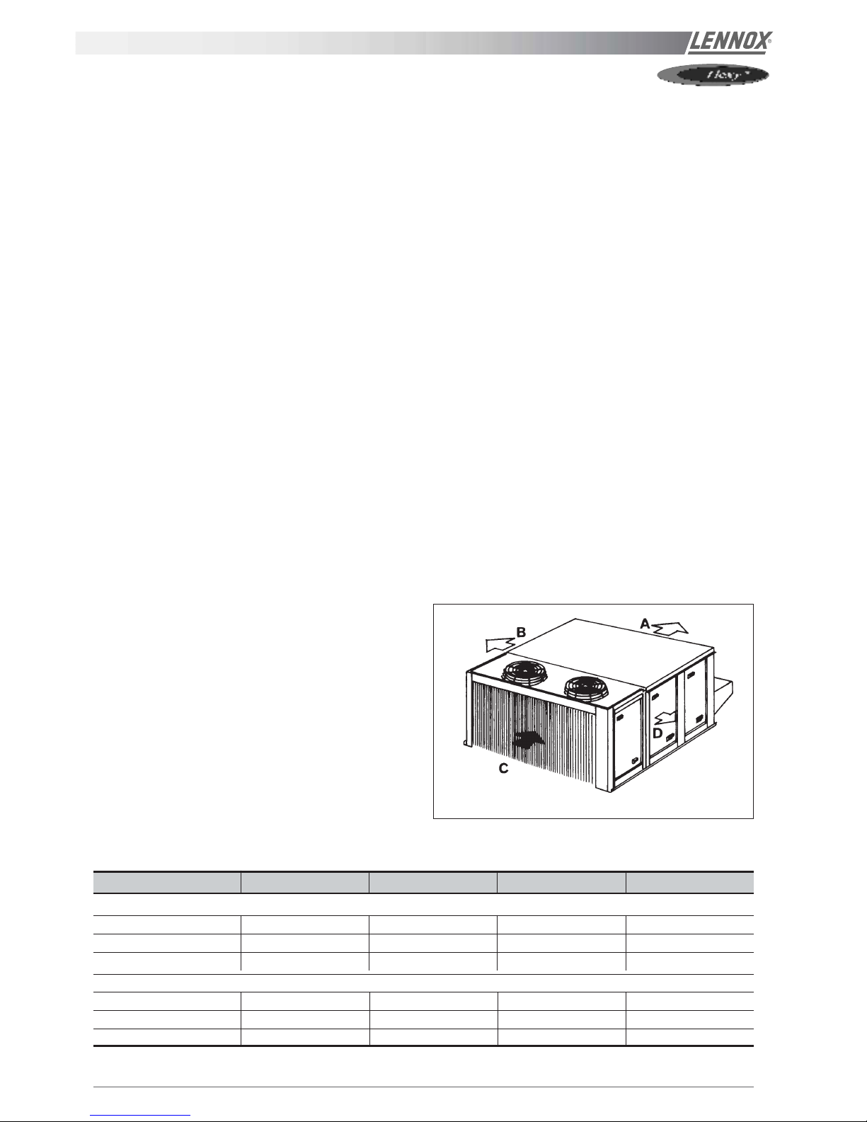
CONNECTIONS
- Ensure that all the pipework crossing walls or roofs are
secured and insulated.
- To avoid condensation problems, be sure all pipes are
insulated according to temperatures of fluids and type of
rooms.
NOTE : The AQUILUX protection sheets fitted to the finned
surfaces must be removed prior to start up.
MODELS ABCD
FC/FH/FG/FD
60
!!
!!
! 140 1400 2000 1400 2300
160 & 190 2000 2000 2000 2300
FX
25 & 30 * 1100 * 1700
35
!!
!!
! 55 * 1300 * 2300
70
!!
!!
! 100 * 1700 * 2300
110
!!
!!
! 170 * 2000 * 2300
* : according to connection
IOM / ROOF-TOP FLEXY™ Series - Page 13
2
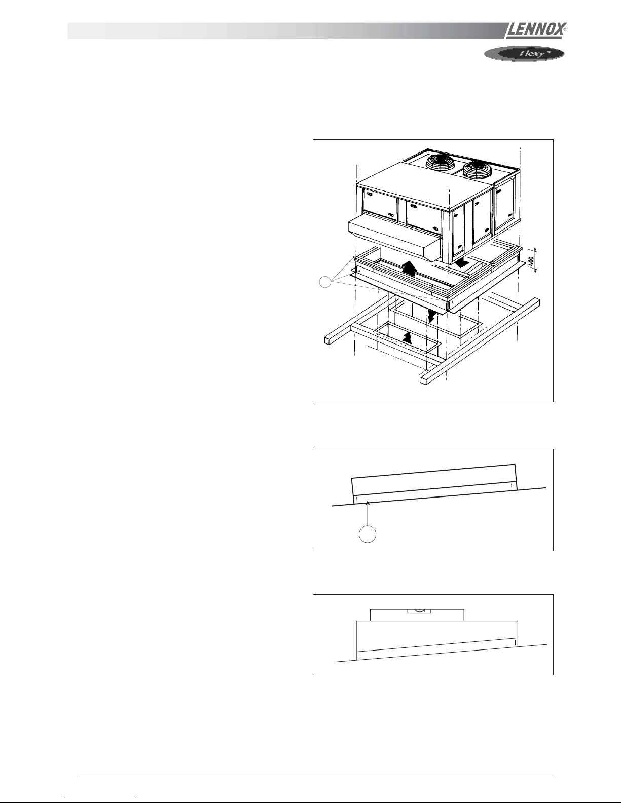
INSTALLATION ON A ROOFMOUNTING FR AME
As levels are adjustable, observe the following
recommendations for correct installation of the equipment.
Above all, ensure that all the adjustable returns are
facing outward (1 - figure 6).
They are usually turned inside-out for transport.
Place the roof mounting frame on the trimmer beam by
first lining up the inlet and then the outlet. (2 - figure 7).
After levelling the frame, fix the surface flaps onto the
trimmer.
1
Figure 6
Figure 7
Figure 8
Page 14 - IOM / ROOF-TOP FLEXY™ Series
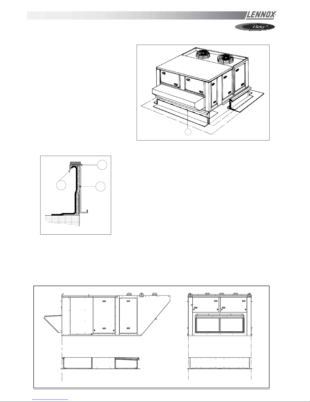
INSTALLATION ON A ROOFMOUNTING FR AME
When the frame is correctly positioned, it is
essential to secure the assembly with welding
seam (20 to 30 mm for every 200 mm) along
the outside, or by using an alternative method
(1 - figure 9).
Assembly joint (1 - figure 10)
Insulate the frame before installation. We recommend the minimum
application of 25 mm thick insulation.
Check that the covering is continuous and watertight (2 - figure 10).
CAUTION : To be effective, it must finsh behind the lip (3 - figure 10)
Before installing the equipment, make sure that the assembly seal is not damaged.
Once in position, the bottom of the equipment must be horizontal and against the roofcurb as shown on figure 11.
The installer must comply to local authority standards and specifications.
1
2
3
Figure 10
Figure 11
1
Figure 9
IOM / ROOF-TOP FLEXY™ Series - Page 15
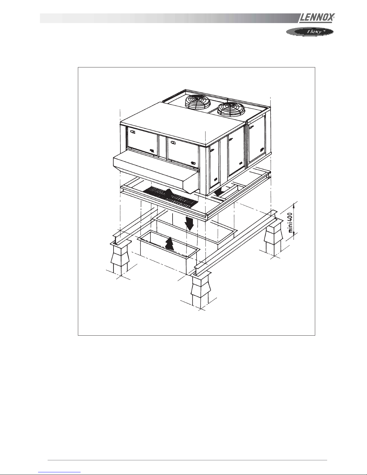
INST ALLATION ON POSTS
The unit can be fitted on corner posts using the frame provided. The minimum height of the posts should be 400mm.
Figure 12
Page 16 - IOM / ROOF-TOP FLEXY™ Series
THIS WORK MUST ONLY BE CARRIED OUT
BY TRAINED REFRIGERA TION ENGINEERS
Before connecting the power :
- Ensure that the power supply between the building and
the unit meets local authority standards and that the
cable specification satisfies the start-up and operating
conditions.
- Ensure that the electrical connections in the control
panel and on the motors are secure.
- Ensure that all drive motors are secure.
- Ensure that the adjustable pulley blocks are secure and
that the belt is tensioned with the transmission correctly
aligned.
- Using the electrical wiring diagram, check the conformity
of the electrical safety devices (circuit breaker settings,
presence and rating of fuses).
At this point attach the manometers to the refrigerant circuit
Powering up the system with the unit isolating
switch
- Close the blower circuit breaker and the 24V control.
- Power up the unit by closing the isolator switch. At this
point the blower should start unless the CLIMATIC™
does not energise the contactor. In this particular case
the blower can be forced by bridging the COM and NO
wires on the connector J1 on the CLIMATIC controller.
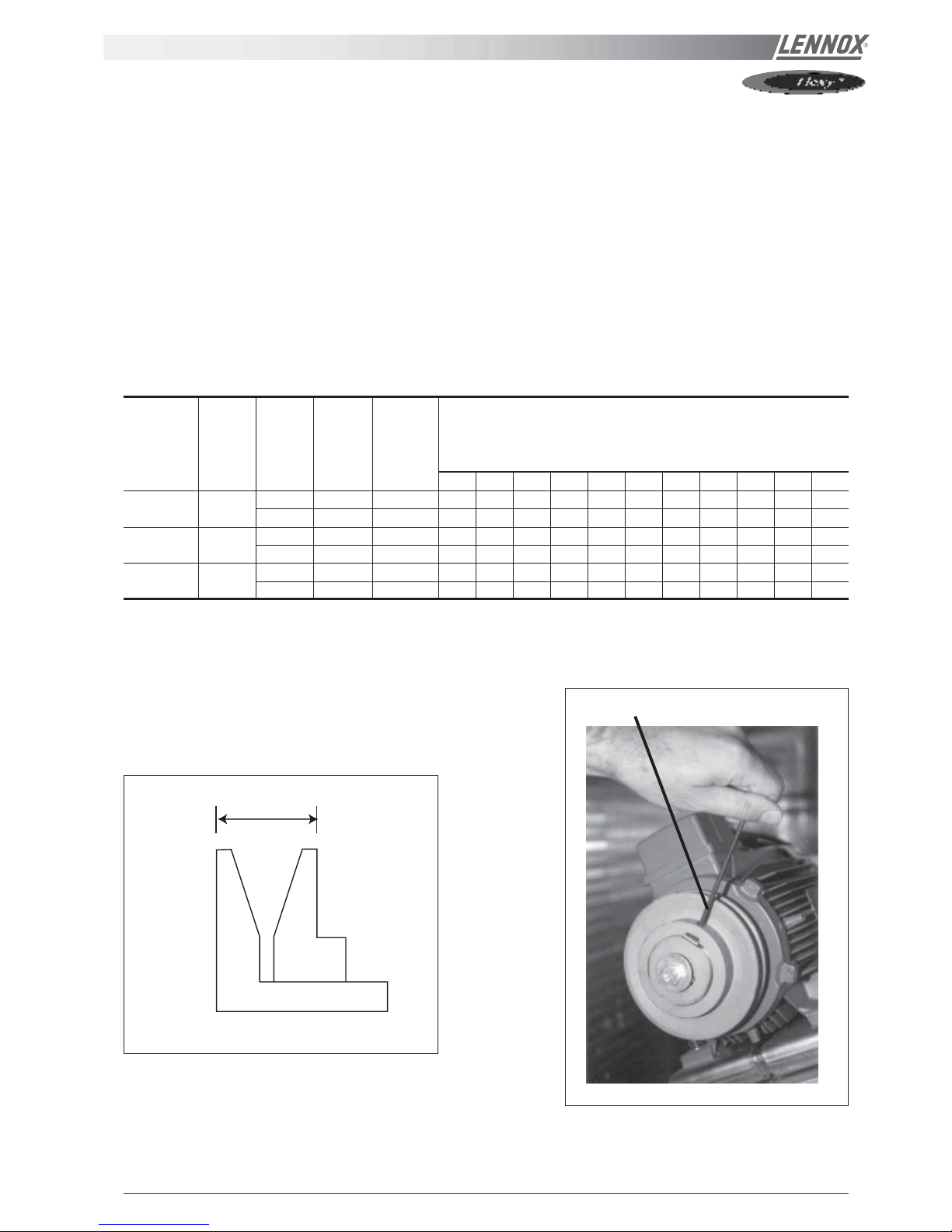
Once the fan is running check the rotation direction.
Refer to the rotation arrow on the fan.
- The fan and other components direction of rotation is
checked during an end of line test. They should
therefore all turn in the same direction.
- If they run in the opposite direction, disconnect the
power supply to the machine at the building's mains
switch, reverse two phases of the incoming supply to the
machine and try again.
Using CLIMATIC™
- Check the voltages recorded against the rated values, in
particular on the system supply fans.
- If the readings on the fans are outside the limits, this
indicates excessive air flow which will affect the
thermodynamic performance. Refer to the "Air flow
balancing" section.
COMMISSIONING
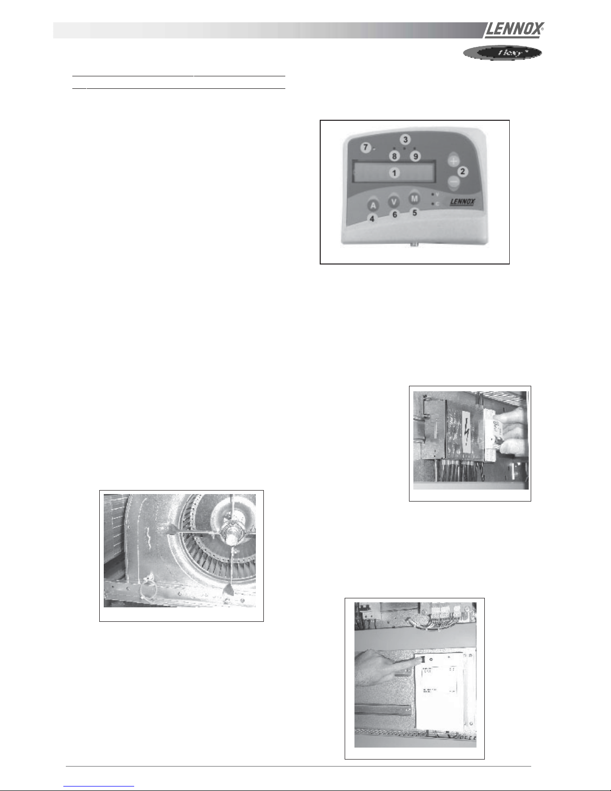
1. Check the configuration
- You will need a KP02 maintenance controller or
CLIMALOOK with KP 14 interface.
1 Liquid crystal display
2 Raise/lower keys
3 "FILTER" Led (flashing red)
4 "ADDRESS" key
5 "MODE" key
6 "VALUE" key
7 "UNIT RUNNING" led
8 "MODE" led
9 "GENERAL ALARM" led.
- The jumpers are
factory set and the
configuration switches
are adjusted
depending on the
option selection and
the type of unit.
- Close the 24V control circuit breakers
- The CLIMATIC™ is starting. Wait for 30 seconds.
1.1 Check and adjust the factory configuration
- Reset the DAD smoke detector (if fitted)
Figure 14
Figure 13
Figure 16
Figure 15
IOM / ROOF-TOP FLEXY™ Series - Page 17
Check the setpoints on CLIMA TIC™ (LF 20).
COMMISSIONING
C0
Password technician Level 63
C98
Type of Unit Refer to configuration table LF20
C99
Type of Unit [off] Flexy [on] Linea On or OFF
C103
Humidity and enthalpy ma na g emen t Option
[off] LINEA
[on] only Flexy with Advanced Pack
C77
(Linea) Authorisation of defrost. Threshold of temperature
of refrigerant fluid ( in°C)
1.0°C for R407c
-3.0°C for R22
C79
Defrost cycle end value indicating the nr of Start-ups of the
condenser fan to signify the end of defrost
Linea set to1
Flexy set to 3
C101
Activation of all seasons control option [ON] / [OFF] if fitted
C73
All seasons control option on FLEXY -
Otherwise – unloading 50% of the compressors in cooling
mode
Set to 20.0°C for Linea
Set to 12°C for Flexy
C74
If option all seasons contr ol – shut d own condenser fans -
Otherwise - 100% unloading of compressors in cooling
mode -
Set to 12.0°C for Linea
Set to 5.0°C for Flexy
C49
Threshold of activation of the power exhaust fan according
to the position of the economiser damper (in %)
Set to 50%
C46
Number of minutes of anticipation per degrees. This allows
an anticipated start-up in the morni ng mode depending on
the outside temperature.
Set to 0
C83
Maximum usable power for electric heat (in %)
C90
Choice of operating mode for KP17 [ON] = KP17 in ON / OFF mode
C91
Identification number for the J-Bus connections
C93
Identification number for the c onne c tio ns lin k b etween
boards
C94
Number of boards linked on the bus
C95
Selection of the operating mode for KP017
C96
Selection of exchange mode for room temperature and
humidity-
C97
Selection of exchange mode for outdoor temperature and
humidity
C100
Activation of the dual-speed option for fan supply (Flexy)
C101
Activation of the all seasons control option
C102
Activation of the optimised defrost option
C05
Fault reset Set to ON
C06
Remote control, On / Off Unit Set to ON ( the unit should start)
Page 18 - IOM / ROOF-TOP FLEXY™ Series
Configuration table LF20
COMMISSIONING
F.A050 11
F.A060 12
F.A070 13
F.A085 14
F.A100 15
F.A120 16
F.A140 17
F.A160 18
F.A190 19
FXA025 20
FXA030 21
FXA035 22
FXA040 23
FXA055 24
FXA070 25
FXA085 26
FXA100 27
FXA110 28
FXA140 29
FXA170 30
F.K050 111
F.K060 112
F.K070 113
F.K085 114
F.K100 115
F.K120 116
F.K140 117
F.K160 118
F.K190 119
FXK025 120
FXK030 121
FXK035 122
FXK040 123
FXK055 124
FXK070 125
FXK085 126
FXK100 127
FXK110 128
FXK140 129
FXK170 130
Switches on KP01
1 = on .......................Option : pressure pick-up on air 500 pa (on FLEXY™ off = sensor 1000 pa)
2 = on | 3 = off ...................Option : hot water coil
2 = off | 3 = on ...................Option : electrical heater
2 = on | 3 = on ...................Option : gas burner
4 = on .......................Option : cycle reversing valve, compressors (heat pump)
5 = on .......................Option : heating of great power / or / pump (except freezing of the hot water coil)
6 = on .......................Option : fresh air, economiser
7 = on .......................Option : fresh air, all fresh air
8 = on .......................Option : KP02 / KP17
POWERING THE UNIT
- Power up the unit by closing the isolator switch (if fitted).
- Close all circuit breakers and power up the unit, remove
the bridge on connector J14 if fitted.
- If now only one of the components rotates in the wrong
direction, disconnect the power supply at the machine's
isolator switch (if fitted) and reverse two of the
component's phases on the terminal within the electrical
panel.
- Check the current drawn against the rated values, in
particular on the supply fan.
- If the readings on the fan are outside the specified limits,
this usually indicates excessive air flow which will affect
the life expectancy and the thermodynamic performances of the unit. This will also increase the risks of water
ingress into the unit. Refer to the "air flow balancing"
section to correct the problem.
At this point attach the manometers to the refrigerant circuit.
RUN TEST
Start unit in cooling mode
Thermodynamic readings using manometers and prevailing
environmental conditions.
No rated values are given here. These depend on the
environmental conditions both outside and inside the building
during operation. However, an experienced refrigeration
engineer will be able to detect any abnormal machine
operation.
Safety test
- "Dirty filter" detection test : vary the set-point value in
respect to the air pressure value. Observe the response
of the CLIMA TIC™.
- Same procedure for detecting "Missing filter" or "Air flow
detection".
- Check the smoke detection function (if fitted).
- Check the Firestat by pressing the test button(if fitted).
- Disconnect the circuit breakers of the outdoor fans and
check the high pressure cut-out points on different
refrigerant circuits.
Reverse cycle test
This test is designed to check the good operation of the 4way reversing valves on heat pump reversible systems. Start
the reverse cycle by adjusting the cold or hot temperature
threshold data according to the indoor and outdoor conditions
at the time of test.
IOM / ROOF-TOP FLEXY™ Series - Page 19
COMMISSIONING report
(4) SUPPLY BLOWER SECTION / VE NT ILATION TRAITEMENT
Type / Type:
Power displayed on plate / Puissance affichée sur la plaque:
Voltage displayed on plate / Tension affichée sur la plaque:
Current displayed on plate / Intensité affichée sur la plaque:
KW
V
A
N°1
……………………
……………………
……………………
N°2
……………………
……………………
……………………
Fan Type / Type de Ventilateur: Forward / Action
Backward / Réaction
Forward / Action
Backward / Réaction
Displayed Belt Length / Longueur Courroie affichée:
mm …………………… ……………………
Tension Checked/ Tension Vérifiée: Yes/Oui No/ Non Yes/Oui No/ Non
Alignment Checked / Alignement Vérifié: Yes/Oui No/ Non Yes/Oui No/ Non
Motor Pulley Dia/ Poulie Moteur Dia: DM mm …………………… ……………………
Fan Pulley Dia/ Poulie Ventilateur Dia: DP mm …………………… ……………………
Fan Speed / Vitesse rotation Ventilateur = Motor rpm x DM / DP
Averaged Measured Amps / Intensité Mesurée moyenne:
rpm
A
……………………
……………………
……………………
……………………
Shaft Mechanical Power (Refer to airflow balancing)
Puissance Mécanique à l’Arbre (Voir section réglage débit)
W …………………… ……………………
Operating point checked / Vérif. Point de fonctionnement: Yes/Oui No/ Non Yes/Oui No/ Non
Estimated Airflow / Estimation Débit d’Air
m3/h
…………………… ……………………
(5) AIRFLOW PRESS. SENSOR CHECK / VERIF. DES SECURITES PRESSOSTATS D’AIR
Measured pressure drop / Pertes de charge au pressostat
…………………………… mbar
Set Points Adjusted / Changement des consignes:
Yes/Oui No/ Non
If Yes enter new values/ Si oui noter les nouvelles consignes:
3410: ………… 3411: ………… 3412: …………
(6) EXTERNAL SENSOR CHECKS / VERIFICATION DES CAPTEURS EXTERNES
Check and record temp. in menu 2110 / Vérifier et mesurer les
températures. Dans menu 2110: Yes/Oui
No/ Non
Check electrical connections / Vérification des
connections électriques: Yes/Oui
No/ Non
100% Fresh Air / 100% Air neuf 100% return Air / 100% Air repris
Supply Temperature / Température Soufflage ………………………..°C ………………………..°C
Return Temperature / Température reprise ………………………..°C ………………………..°C
Outdoor Temperature / Température extérieure ………………………..°C ………………………..°C
(7) MIXING AIR DAMPERS CHECKS / VERIFICATIONS VOLETS DE MELANGE
Dampers open & close freely/
Volets s’ouvrent et se ferment OK
% Minimum FA:
%minimum Air Neuf:
Power exhaust checked/
Ventilateur extraction
Enthalpy s ensor(s) checked/
Control enthalpie installé
Yes/Oui No/ Non ……………..% Yes/Oui No/ Non Yes/Oui No/ Non
Site details / Informations site
Site / Site
Unit Ref/ N° Affaire
Installer/ Installateur
………………………………………
……………………………………....
………………………………………
Controller/ Contrôleur
Model/Modele
Serial No/ No Série
Refrigerant / Réfrigérant
………………………………….
……………….…………………
…………………………………
…………………………………
(1) ROO F IN S TALLATION / INSTALLATION SUR LE TOIT
Sufficient Access OK / Accès Suffisants
Yes/Oui
No/ Non
Condensate drain fitted / Drainage condensats
Installé Yes/Oui No/ Non
Roofcurb / Costière
OK Not OK/PasOK
(2) CONNECTIONS CHECK / VERIFICATIONS DE RACCORDEM ENTS
Phase check/ Vérification des Phases
Yes / Oui
No / Non
Voltage between Phases
Tension entre Phases
1 / 2
……………….
2 / 3
……………….
1 / 3
……………….
(3) CLIMATIC CONFIGURATION CHECK / VERIFIER LA CONFIGURATION CLIMATIC
CLIMATIC 50 Configured according to the Options and Specifications / CLIMATIC 50 configuré en fonction des options et des
spécifications: Yes/Oui
No/ Non
Page 20 - IOM / ROOF-TOP FLEXY™ Series
COMMISSIONING report
(8) REFRIGERATION S ECT ION / SECTION REFRIGERATION
Outdoor Fan Motor Current / Intensité Moteurs Batterie externe: Check Rotation
Motor 1 / Moteur 1 L1 ……..A L2 ……..A L3 ……A Yes/Oui No/ Non
Motor 2 / Moteur 2 L1 ……..A L2 ……..A L3 ……A Yes/Oui No/ Non
Compressor
Voltage/ Tension
Compresseur.
Motor 3 / Moteur 3 L1 ……..A L2 ……..A L3 ……A Yes/Oui No/ Non Comp1: …….. V
Motor 4 / Moteur 4 L1 ……..A L2 ……..A L3 ……A Yes/Oui No/ Non Comp2: …….. V
Motor 5 / Moteur 5 L1 ……..A L2 ……..A L3 ……A Yes/Oui No/ Non Comp3: …….. V
Motor 6 / Moteur 6 L1 ……..A L2 ……..A L3 ……A Yes/Oui No/ Non Comp4: …….. V
Compressor Amps COOLING / Intensité
Compresseur MODE FROID
Pressures & Temperatures / Pressions & températures
Temperatures / Temperatures Pressures / Pressions
Phase 1 Phase 2 Phase 3
Suction/ Asp Disch / refoul
LP/ BP HP / HP
Comp 1 …..… A …..… A …..… A ……… °C ……… °C ……… Bar ……… Bar
Comp 2 …..… A …..… A …..… A ……… °C ……… °C ……… Bar ……… Bar
Comp 3 …..… A …..… A …..… A ……… °C ……… °C ……… Bar ……… Bar
Comp 4 …..… A …..… A …..… A ……… °C ……… °C ……… Bar ……… Bar
Check Reversing valves./
Vérifier vannes d’inversion:
Valve1/Vanne1: Yes/Oui
No/ Non
Valve2/Vanne2: Yes/Oui
No/ Non
Valve3/Vanne3: Yes/Oui
No/ Non
Valve4/Vanne4: Yes/Oui
No/ Non
Compressor Amps HEATING / Intensité
Compresseur en Pompe à Chaleur
Pressures & Temperat ur es / P re ssion s & températures
Temperatures / Temperatures Pressures / Pressions
Phase 1 Phase 2 Phase 3
Suction/ Asp Disch / refoul
LP/ BP HP / HP
Comp 1 …..… A …..… A …..… A ……… °C ……… °C ……… Bar ……… Bar
Comp 2 …..… A …..… A …..… A ……… °C ……… °C ……… Bar ……… Bar
Comp 3 …..… A …..… A …..… A ……… °C ……… °C ……… Bar ……… Bar
Comp 4 …..… A …..… A …..… A ……… °C ……… °C ……… Bar ……… Bar
HP cut out / Coupure HP ……Bar LP cut out / Coupu re séc urité BP ………..…... Bar
Refrigerant charge / Charge réfrigérant C1 : ………..kg C2 : ………..kg C3 : ………..kg C4 : ………..kg
(9) ELECTRIC HEATER SECTION / SECTION RECHAUFFEUR ELECTRI Q UE
Type / Type: …………………………………………………. Serial No/ No Série.:………………………..
AMPS 1st stage (Baltic) / Intensité 1er étage (Baltic) AMPS 2nd stage (Baltic) / Intensité 2e étage (Baltic)
1 ………………. 2 ………………. 3 ………………. 1 ………………. 2 ………………. 3 ……………….
(10) HOT WATER COIL SECTION / SECTION BATTERIE EAU CHAUDE
Check Three Way Valve Movement / Vérification Mouvement Vanne trois voies: Yes/Oui No/ Non
(11) GAS HEATING SECTION / RAMPE GAZ
Gas Burner N°1 / Brûleur gaz N°1 Gas Burner N°2 / Brûleur gaz N°2
Size / Taille:
……………………….
Valve type / Type vanne:
…………………….
Size / Taille:
……………………….
Valve type / Type vanne:
…………………….
Pipe size/ tuyauterie:
Gas type / Type gas : G…….
Pipe size/ tuyauterie
Gas type / Type gas : G…….
Line press./ press. ligne :
………………………
Drop test / test pression
Yes/Oui No/ Non
line press./ press. ligne :
………………………
Drop test / test pression
Yes/Oui No/ Non
Check manifold pressure/ Pression injection:
High fire/Grande allure…….…Low fire/Petite allure………..
Check manifold pressure/ Pression injection:
High fire/Grande allure…….…... Low fire/Petite allure………..
Pressure cut out airflow press switch / Pression coupure
pressostat débit d’air : ……………………mbar /Pa
Pressure cut out airflow press switch / Pression coupure
pressostat débit d’air : ……………………mbar /Pa
Motor amps
I moteur:
……….A
Flue temp /
temp fumées
……… °C
CO2 %:
………%
CO ppm:
………%
Motor Amps
I Moteur:
……….A
Flue temp /
temp fumées
………. °C
CO2 %:
………%
CO ppm:
………%
(12) REMOTE CONTROL BMS CHECK / VERIFICATIONS BMS CONTROL A DISTANCE
Type / Type:
……………………….
Sensor type / Type Capteur:
…………………………..
KP07 KP/17 checked/ vérifiées:
Yes/Oui
No/ Non
Interconnect wiring checked:
Yes/Oui No/ Non
Comments.....................................................................................................................................................................................
.......................................................................................................................................................................................................
.......................................................................................................................................................................................................
IOM / ROOF-TOP FLEXY™ Series - Page 21
VENTILATION
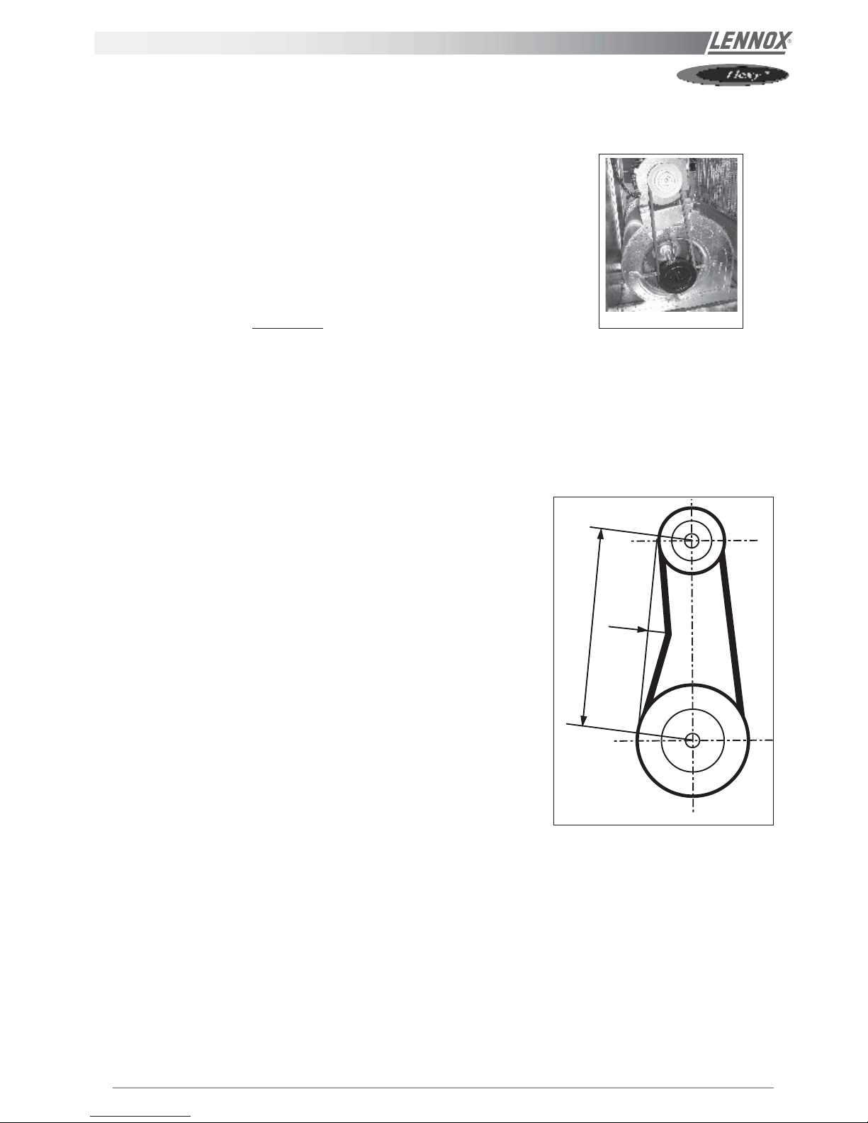
BELT TENSION
On delivery, the drive belts are new and correctly tensioned. After the first 50 operating
hours check and adjust the tension. 80% of the total elongation of belts is generally
produced during the first 15 hours of operation.
Before adjusting the tension, make sure that the pulleys are correctly aligned.
To tension the belt, set the height of motor support plate by moving the plate
adjustment screws.
This recommended deflection is 16 mm per metre from centre to centre.
Check that according to the diagram below (figure 18), the following ratio remains
the same.
A (m)
= 20
P (mm)
The belts should always be replaced when :
- the disk is set to maximum,
- the belt rubber is worn or the wire is visible.
Replacement belts must have the same rated size as the ones they are replacing.
If a transmission system has several belts, they must all be from the same
manufacturing batch (compare serial numbers).
NOTE :
An under-tensioned belt will slip, heat and wear prematurely. On the other hand, if
a belt is over-tensioned, the pressure on the bearings will cause them to over-heat
and wear prematurely. Incorrect alignment will also cause the belts to wear
prematurely.
A
P
Figure 18
Figure 17
Page 22 - IOM / ROOF-TOP FLEXY™ Series
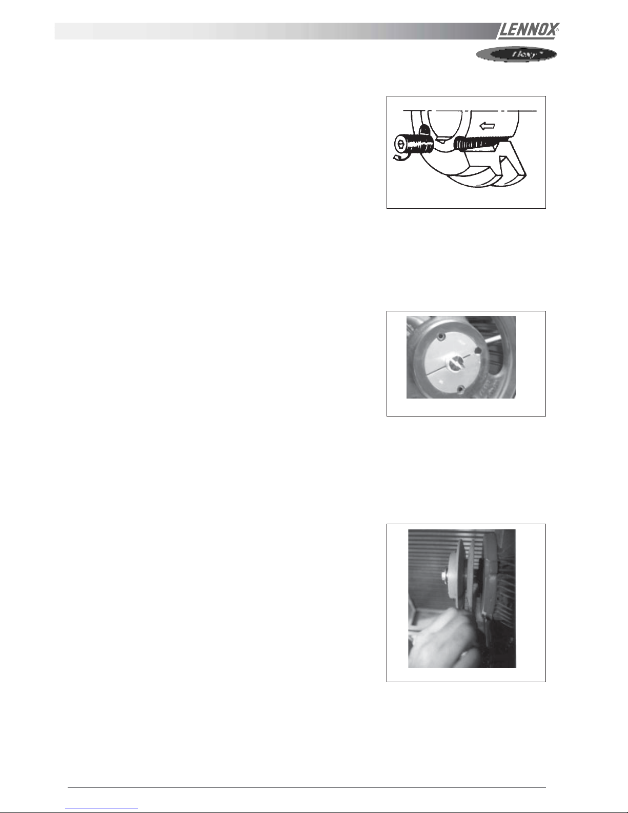
VENTILaTION : PULLEYS
MOUNTING AND ADJUSTING PULLEYS
Fan pulley removal
Remove the 2 screws and put one of them in the extraction
threaded screw.
Screw in fully. The hub and the pulley will separate from each
other.
Remove the hub and the pulley by hand without damaging
the machine.
Fan pulley installation
Clean and de-grease the shaft, hub and conical bore of the
pulley. Lubricate the screws and install the hub and pulley.
Position the screws without turning them.
Place the assembly on the shaft and screw in the screws
alternatively and evenly. Using a mallet or a hammer with a
wooden wedge, tap on the face of the hub to keep the
assembly in place. Torque the screws to 30 Nm.
Take the pulley in both hands and shake it vigorously to make
sure everything is in place.
Fill the holes with grease for protection.
NOTE : During installation, the key should never protrude out
of its groove.
After 50 operating hours, check that the screws are still in
place.
Motor pulley installation and removal
The pulley is held in position by the key and a screw located
in the groove. After unlocking, removing this screw by pulling
against the shaft spindle (if necessary, use a mallet and tap
uniformly on the hub to remove it).
To assemble, proceed in the reverse order after having
cleaned and de-greased the motor shaft and the pulley bore.
Pulleys alignment
After adjusting one or both of the pulleys, check the
transmission alignment using a ruler placed on the inner face
of the two pulleys.
NOTE : The warranty may be affected if any major modification
is made to the transmission without obtaining our agreement
beforehand.
Figure 19
Figure 20
Figure 21
IOM / ROOF-TOP FLEXY™ Series - Page 23
The actual resistance of ductwork systems is not always identical to the calculated theoretical values. To rectify this, it may be
necessary to modify the pulley and belt setting. To this effect, the motors are fitted with variable pulleys.
Measure the absorbed amps
If the absorbed amps are greater than the rated values, the ventilation system has a lower pressure drop than anticipated.
Reduce the flow by reducing the rpm. If the system resistance is significantly lower than design, there is a risk that the motor
will overheat resulting in an emergency cut out.
If the absorbed amps are lower than the rated values, your system has a higher pressure drop than anticipated. Increase the
flow by increasing the rpm. At the same time you will increase the absorbed power which may result in having to increase the
motor size.
To carry out the adjustment and to avoid a time-consuming re-start, stop the machine and if necessary lock the main switch.
First unscrew the 4 Allen screw(s) on the pulley (see figure 23).
0,5 1 1,5 2 2,5 3 3,5 4 4,5 5,0 5,5
8450 /
120
95 116 5 113,9 111,8 109,7 107,6 105,5 103,4 101,3 99,2 97,1 95,0 D8450 20,2 28,0 5 21,0 21,8 22,5 23,3 24,1 24,9 25,7 26,4 27,2 28,0 8550 /
136
110 131 5 128,9 126,8 124,7 122,6 120,5 118,4 116,3 114,2 112,1 110,0
D8550 20,6 31,2 5 21,6 22,7 23,8 24,8 25,9 26,9 28,0 29,1 30,1 31,2 8670
171
145 166 5 163,9 161,8 159,7 157,6 155,5 153,4 151,3 149,2 147,1 145,0 D8670 20,5 31,1 5 21,5 22,7 23,8 24,8 25,7 26,9 27,9 29,0 30,0 31,1 -
The easiest way to determine the fan rotation speed is to
use a tachometer. If not available the fan rpm can be
estimated using the following two methods.
1st Method with the pulley secured in place :
L
Measure the distance between the two outside faces of the
pulley.
Using table 1 the motor pulley actual diameter can be
estimated
ALLEN WRENCH 4
AIRFLOW BALANCING
Pulley
type
Pulley
external
Ø
Min Ø
/
Min dist.
Max Ø
/
Max dist.
nr of
turns
from fully
closed to
fully
open
Actual Ø (DM) or distance between faces for a given
number of turns from fully closed with SPA belt in (mm)
Figure 22
Figure 23
Page 24 - IOM / ROOF-TOP FLEXY™ Series
AIRFLOW BALANCING
2nd method when adjusting the pulley :
- Close the pulley fully and count the number of turns
from fully closed position. Using table 1 determine the
motor pulley actual diameter.
- Record the fix fan pulley diameter.(DF)
- Determine the fan speed using the following formula:
rpm
FAN
= rpm
MOTOR
x DM / D
F
Where :
rpm
MOTOR
: ....... from the motor plate or table 2
DM : ...................... from t able 1
DF: ........................ from machine
Once the pulleys are adjusted and the belt checked and
tensioned, start the fan motor and record the Amps and
Voltage between the phases :
Using the measured data and table 2
- Theoretical mechanical power at the fan shaft :
P
meca fan
=P
meca Motor
x η
Transmission
P
meca fan
=P
elec
x η
meca motor
x η
Transmission
P
meca fan
= V x I x √3 x cosϕ x η
meca motor
x η
Transmission
This formula can be approximated in this way
P
meca fan
= V x I x 1.73 x 0.85 x 0.76 x 0.9
With the fan "rpm" and the mechanical power at the fan shaft
an operating point and the supplied airflow can be estimated
using the fan curves.
CHECKING AIRFLOW AND ESP
Using the fan curves on page 25, 26, 27, the airflow, the total
pressure available (P
TOT
) and the corresponding dynamic
pressure (Pd) can now be estimated, for a specific operating
point;
The next step consist in estimating the pressure losses across
the unit.
This can be achieved using the "dirty filter pressure sensor"
and the accessories pressure drop table:
Also the pressure drop due to the duct inlet into the roof-top
unit can be taken as 20 to 30 Pa.
∆P
INT
= ∆P
filter
+ coil + P
Inlet
+ ∆P
Options
using the results from above, the external static pressure (ESP)
can then be estimated:
ESP = P
TOT
- Pd - ∆P
INT
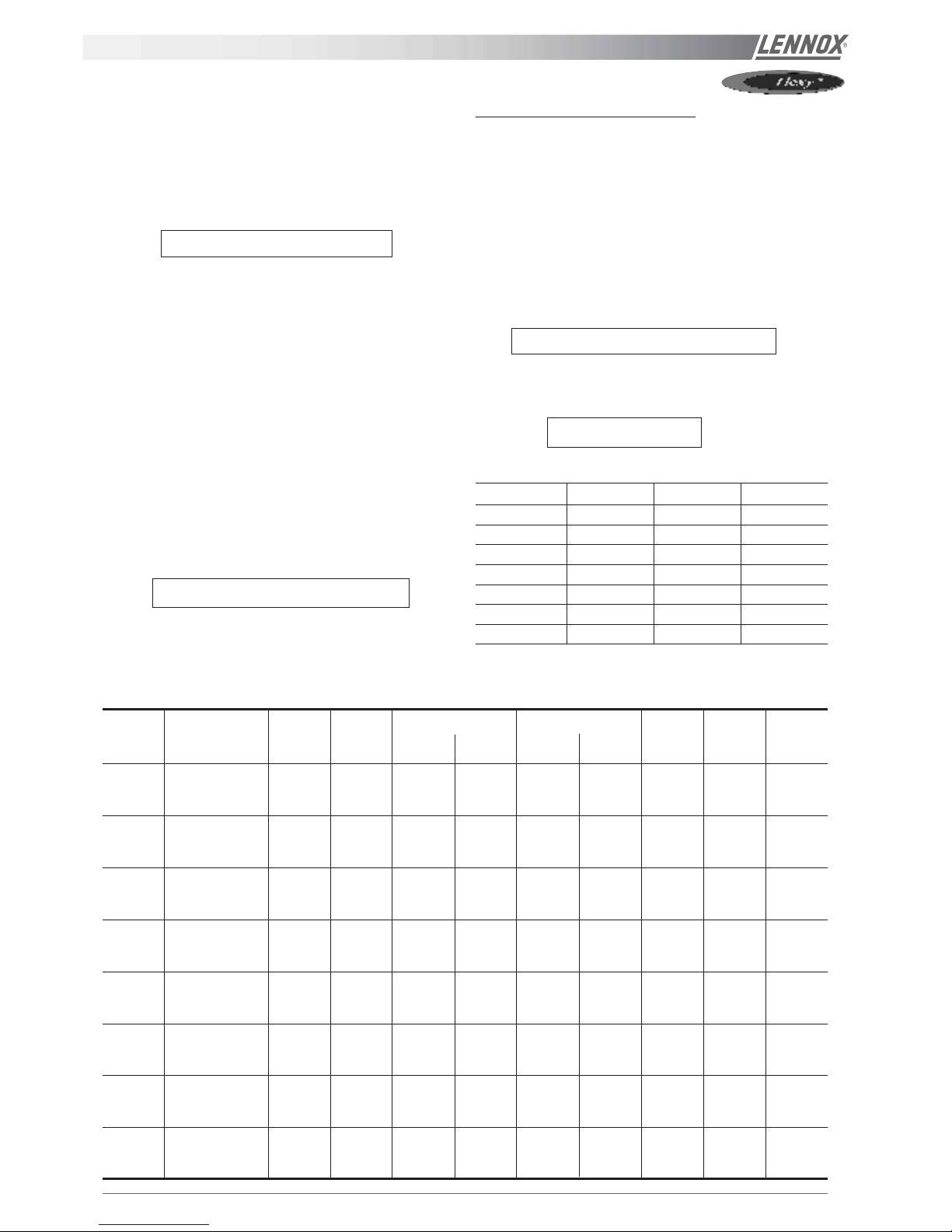
T able 2
Motor Size Nom, Speed Cos meca motor
0,75 kW 1400 rpm 0,77 0,70
1,1 kW 1425 rpm 0,82 0,77
1,5 kW 1430 rpm 0,81 0,75
2,2 kW 1430 rpm 0,81 0,76
3,0 kW 1425 rpm 0,78 0,77
4 kW 1425 rpm 0,79 0,80
5,5 kW 1430 rpm 0,82 0,82
Economiser EU7 Hot water coil Electric heater Roofcurb Horizontal Gaz
100% open Filter S H S H Base frame Roofcurb H
SIZE Air flow (m3/h) (Pa) (Pa) (Pa) (Pa) (Pa) (Pa) (Pa) (Pa) (Pa)
Min. 10 000 4 67 12 14 5 8 10 41 22
60 Nom. 12 000 6 93 16 19 8 8 11 59 26
Max. 15 000 9 135 24 28 8 10 13 92 31
Min. 12 000 6 56 6 12 5 5 13 59 29
70 Nom. 14 000 8 73 8 16 5 5 16 80 34
Max. 18 000 12 113 13 25 8 8 22 132 47
Min. 14 000 8 73 8 16 5 8 18 44 7
85 Nom. 16 000 10 113 13 25 8 8 26 57 10
Max. 22 000 16 159 18 36 8 10 32 109 12
Min. 16 000 10 93 10 20 8 10 26 57 10
100 Nom. 20 000 14 135 15 30 10 13 32 90 12
Max. 22 000 16 159 18 36 13 15 38 109 15
Min. 18 000 12 113 13 25 10 13 32 33 29
120 Nom. 22 000 16 159 18 36 13 15 38 49 35
Max. 24 000 18 184 21 41 15 18 44 58 40
Min. 20 000 14 135 15 30 10 15 35 40 31
140 Nom. 24 000 18 184 21 41 15 18 46 58 40
Max. 25 000 19 197 22 44 15 20 50 63 43
Min. 22 000 16 87 9 18 8 8 24 49 45
160 Nom. 28 000 22 132 13 27 8 10 30 79 56
Max. 32 000 26 165 17 34 13 13 34 103 64
Min. 24 000 18 101 10 20 10 10 34 58 64
190 Nom. 33 000 27 174 18 36 13 13 41 109 77
Max. 36 000 30 201 21 41 13 15 48 130 89
Table 5.52
IOM / ROOF-TOP FLEXY™ Series - Page 25
AIRFLOW BALANCING
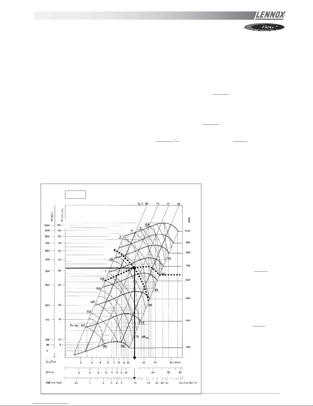
EXAMPLE
The unit used for this example is a FHK 060N with standard supply and return airflow configuration. It is also fitted with an
economiser and an electric heater type H.
It is fitted with a AT 18-18 fan which curve is shown on page xxx and a 2.2 kW motor.
- Motor rpm : 1430 rpm
- cos ϕ = 0.81
- Voltage = 400 V
- Current = 4,68A
P
mech fan
= V x I x
√√
√√
√ 3 x cos
ϕ ϕ
ϕ ϕ
ϕ x
ηη
ηη
η
mech motor
x
ηη
ηη
η
Transmission
= 400 x 4.68 x
√√
√√
√ 3 x 0.81 x 0.76 x 0.9 = 1,79 kW
The unit is also fitted with a transmission kit 1
- Fixed Fan pulley : 250 mm
- Motor adjustable pulley type "8450" opened 1 turn from fully closed or measured distance between pulley end plates is
21,8 mm: from table xxx it can be determined that the motor pulley has a diameter of 111,8 mm
rpm
FAN
= rpm
MOTOR
x DM / DF = 1430 x 118,2 / 250 = 640 rpm
Using the fan curve below the operating point can be located.
It can be determined that the fan is providing approximately
12 000 m3/h with a total pressure P
TOT
= 420 Pa
640
420
12
10
1.79
Hd (mmH2O)
AT 18-18
The pressure losses in the unit are the
sum of all pressure drops across the
different parts of a unit :
- Coil and filter (measured) = 105 Pa
- Options = 6 Pa for economiser and
8 Pa for electric heater H
∆P = 105 + 6 + 8 =
119 Pa
The dynamic pressure at 1200m3/h is
given at the bottom of the fan curve
Pd = 100 Pa
The external static pressure available is
therefore
ESP = P
TOT
- Pd - ∆PI
NT
= 420 - 100 - 119 = 201 Pa
Figure 24
Page 26 - IOM / ROOF-TOP FLEXY™ Series
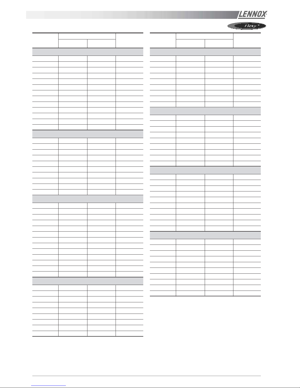
AIRFLOW BALANCING
KIT FAN TYPE CURVE
NR PICTURE
SINGLE TWIN ON PAGE
FC/FH/FD... 060 - Standard
K1 AT 18-18 S - 34
K2 AT 18-18 S - 34
K3 AT 18-18 S - 34
K4 AT 18-18 S - 34
K5 AT 18-18 S - 34
K6 AT 18-18 S - 34
K7 AT 18-18 S - 34
K8 AT 18-18 S - 34
K9 AT 18-18 S - 34
K10 AT 18-18 S - 34
K11 AT 18-18 S - 34
K12 AT 18-18 S - 34
K13 AT 18-18 S - 34
FC/FH/FD... 070 - Standard
K1 AT 18-18 S - 34
K2 AT 18-18 S - 34
K3 AT 18-18 S - 34
K4 AT 18-18 S - 34
K5 AT 18-18 S - 34
K6 AT 18-18 S - 34
K7 AT 18-18 S - 34
K8 AT 18-18 S - 34
K9 AT 18-18 S - 34
K10 AT 18-18 S - 34
FC/FH/FD... 085 - Standard
K1 AT 15-15 G2L - 32
K2 AT 15-15 G2L - 32
K3 AT 15-15 G2L - 32
K4 AT 15-15 G2L - 32
K5 AT 15-15 G2L - 32
K6 AT 15-15 G2L - 32
K7 AT 15-15 G2L - 32
K8 AT 15-15 G2L - 32
K9 - AT 15-15 S 32
K10 AT 15-15 G2L - 32
K11 - AT 15-15 S 32
K12 AT 15-15 G2L - 32
K13 - AT 15-15 S 32
FC/FH/FD... 100 - Standard
K1 AT 15-15 G2L - 32
K2 AT 15-15 G2L - 32
K3 AT 15-15 G2L - 32
K4 AT 15-15 G2L - 32
K5 AT 15-15 G2L - 32
K6 - AT 15-15 S 32
K7 AT 15-15 G2L - 32
K8 - AT 15-15 S 32
K9 AT 15-15 G2L - 32
KIT FAN TYPE CURVE
NR PICTURE
SINGLE TWIN ON PAGE
FC/FH/FD... 120 - Standard
K1 - AT 18-18 S 34
K2 - AT 18-18 S 34
K3 - AT 18-18 S 34
K4 - AT 18-18 S 34
K5 - AT 18-18 S 34
K6 - AT 18-18 S 34
K7 - AT 18-18 S 34
K8 - AT 18-18 S 34
K9 - AT 18-18 S 34
FC/FH/FD... 140 - Standard
K1 - AT 18-18 S 34
K2 - AT 18-18 S 34
K3 - AT 18-18 S 34
K4 - AT 18-18 S 34
K5 - AT 18-18 S 34
K6 - AT 18-18 S 34
K7 - AT 18-18 S 34
K8 - AT 18-18 S 34
K9 - AT 18-18 S 34
FC/FH/FD... 160 - Standard
K1 - AT 18-18 S 34
K2 - AT 18-18 S 34
K3 - AT 18-18 S 34
K4 - AT 18-18 S 34
K5 - AT 18-18 S 34
K6 - AT 18-18 S 34
K7 - AT 18-18 S 34
K8 - AT 18-18 S 34
K9 - AT 18-18 S 34
K10 - AT 18-18 S 34
FC/FH/FD... 190 - Standard
K1 - AT 18-18 S 34
K2 - AT 18-18 S 34
K3 - AT 18-18 S 34
K4 - AT 18-18 S 34
K5 - AT 18-18 S 34
K6 - AT 18-18 S 34
K7 - AT 18-18 S 34
K8 - AT 18-18 S 34
K9 - AT 18-18 S 34
K10 - AT 18-18 S 34
IOM / ROOF-TOP FLEXY™ Series - Page 27
AIRFLOW BALANCING
KIT FAN TYPE CURVE
NR PICTURE
SINGLE TWIN ON PAGE
FC/FH/FD... 085 - Side discharge
K14 - AT 15-15 S 32
K15 - AT 15-15 S 32
K16 - AT 15-15 S 32
K17 - AT 15-15 S 32
K18 - AT 15-15 S 32
K19 - AT 15-15 S 32
K20 - AT 15-15 S 32
K21 - AT 15-15 S 32
FC/FH/FD... 100 - Side discharge
K10 - AT 15-15 S 32
K11 - AT 15-15 S 32
K12 - AT 15-15 S 32
K13 - AT 15-15 S 32
K14 - AT 15-15 S 32
K15 - AT 15-15 S 32
K16 - AT 15-15 S 32
K17 - AT 15-15 S 32
K18 - AT 15-15 S 32
K19 - AT 15-15 S 32
FC/FH/FD... 120 - Side discharge
K10 - AT 18-13 S 33
K11 - AT 18-13 S 33
K12 - AT 18-13 S 33
K13 - AT 18-13 S 33
K14 - AT 18-13 S 33
K15 - AT 18-13 S 33
K16 - AT 18-13 S 33
K17 - AT 18-13 S 33
K18 - AT 18-13 S 33
FC/FH/FD... 140 - Side discharge
K10 - AT 18-13 S 33
K11 - AT 18-13 S 33
K12 - AT 18-13 S 33
K13 - AT 18-13 S 33
K14 - AT 18-13 S 33
K15 - AT 18-13 S 33
K16 - AT 18-13 S 33
K17 - AT 18-13 S 33
Page 28 - IOM / ROOF-TOP FLEXY™ Series
AIRFLOW BALANCING
KIT FAN TYPE CURVE
NR PICTURE
SINGLE TWIN ON PAGE
FG... 060 - Gas
K1 - AT 15-15 S 32
K2 - AT 15-15 S 32
K3 - AT 15-15 S 32
K4 - AT 15-15 S 32
K5 - AT 15-15 S 32
K6 - AT 15-15 S 32
K7 - AT 15-15 S 32
K8 - AT 15-15 S 32
K9 - AT 15-15 S 32
K10 - AT 15-15 S 32
FG... 070 - Gas
K1 - AT 15-15 S 32
K2 - AT 15-15 S 32
K3 - AT 15-15 S 32
K4 - AT 15-15 S 32
K5 - AT 15-15 S 32
K6 - AT 15-15 S 32
K7 - AT 15-15 S 32
K8 - AT 15-15 S 32
K9 - AT 15-15 S 32
K10 - AT 15-15 S 32
K11 - AT 15-15 S 32
FG... 085 - Gas
K1 - AT 15-15 S 32
K2 - AT 15-15 S 32
K3 - AT 15-15 S 32
K4 - AT 15-15 S 32
K5 - ADN 325L 36
K6 - AT 15-15 S 32
K7 - ADN 325L 36
K8 - AT 15-15 S 32
K9 - AT 15-15 S 32
K10 - ADN 325L 36
K11 - ADN 325L 36
FG... 100 - Gas
K1 - AT 15-15 S 32
K2 - AT 15-15 S 32
K3 - AT 15-15 S 32
K4 - AT 15-15 S 32
K5 - ADN 325L 36
K6 - AT 15-15 S 32
K7 - AT 15-15 S 32
K8 - ADN 325L 36
K9 - AT 15-15 S 32
K10 - ADN 325L 36
KIT FAN TYPE CURVE
NR PICTURE
SINGLE TWIN ON PAGE
FG... 120 - Gas
K1 - ADN 370L 37
K2 - ADN 370L 37
K3 - ADN 370L 37
K4 - ADN 370L 37
K5 - ADN 370L 37
K6 - ADN 370L 37
K7 - ADN 370L 37
K8 - ADN 370L 37
FG... 137 - Gas
K1 - ADN 370 L 37
K2 - ADN 370 L 37
K3 - ADN 370 L 37
K4 - ADN 370 L 37
K5 - ADN 370 L 37
FG... 160 - Gas
K1 - ADN 450 L 38
K2 - ADN 450 L 38
K3 - ADN 450 L 38
K4 - ADN 450 L 38
K5 - ADN 450 L 38
K6 - ADN 450 L 38
K7 - ADN 450 L 38
K8 - ADN 450 L 38
K9 - ADN 450 L 38
K10 - ADN 450 L 38
FG... 190 - Gas
K1 - ADN 450 L 38
K2 - ADN 450 L 38
K3 - ADN 450 L 38
K4 - ADN 450 L 38
K5 - ADN 450 L 38
K6 - ADN 450 L 38
K7 - ADN 450 L 38
K8 - ADN 450 L 38
K9 - ADN 450 L 38
K10 - RDN 450 K 35
 Loading...