

Page 1

APPLICATION
GUIDE
FAC - FAG - FAH - FAM
Air cooled rooftop packaged unit
FLEXAIR
85 230 kW
FLEXAIR-AGU-1505-E
lennoxemeia.com
Page 2

Page 3

TABLE OF CONTENTS
FLEXAIR
APPLICATION GUIDE
GENERAL DESCRIPTION
1. 4
OPTIONS DESCRIPTION
2. 14
GENERAL DATA
3. 22
OPTIONS DATA
4. 26
Ref : FLEXAIR-AGU-1505-E
STANDARD UNIT PERFORMANCES
5. 276
FAN PERFORMANCES
6. 42
HEAT RECOVERY SOLUTIONS PERFORMANCES
7. 45
HEATING AUXILIARIES PERFORMANCES
8. 47
ACOUSTIC DATA
9. 52
ELECTRICAL DATA
10. 54
DIMENSIONAL DATA
11.
OPTIONS WEIGHTS AND ACCESSORIES PRESSURE DROPS
12.
56
75
Product designed and manufactured under quality management
systems certifi ed ISO 9001 and ISO 14001.
All the technical and technological information contained in this manual, including any drawing and technical descriptions provided
by us, remain the property of Lennox and must not be utilised (except in operation of this product), reproduced, issued to or made
available to third parties without the prior written agreement of Lennox.
Application Guide /FLEXAIR-AGU-1505-E
www.eurovent-certifi cation.com
www.certifl ash.com
Our company’s products comply
with European standards.
• 1 •
Page 4

• 2 •
Application Guide / FLEXAIR-AGU-1505-E
Page 5

MODEL NUMBER DESCRIPTION
EXAMPLE :
F A C 300 D N M 1 M
FLEXAIR
F
Air cooled
A
Water cooled
W
No condenser
N
M
H
Revision number
R410A
HFO
400V/3/50
M
230V/1/50
T
Cooling
C
Heat pump
H
gas fi red
G
dual fuel
M
heat recovery
X
Cooling capacity in kW
S
D
T
F
High heat
H
Standard heat
S
No heat
N
1 Circuit
2 Circuits
3 Circuits
4 Circuits
No refrigerant
N
Application Guide /FLEXAIR-AGU-1505-E
• 3 •
Page 6

1- GENERAL DESCRIPTION
SUSTAINABLE ENERGY
DEVELOPMENT CHALLENGES
Faced with challenges relating to competitiveness and climate
change, Europe has launched several initiatives for an intelligent
energy strategy.
New regulations refl ect the European Union’s commitments on
climate change and its determination to reach 20% effi ciency
improvement in buildings by 2020.
EPBD
ENERGY PERFORMANCE OF
BUILDING DIRECTIVE
One of the major requirements of the new EPBD is to set Energy
Certifi cates for buildings which grade the energy effi ciency based
on the building annual energy consumption. Soon companies
will have to display their energy certifi cates to the public.
THE EXPERIENCE & COMMITMENT OF
THE EUROPEAN LEADER TO DRIVE
CONTINUOUS ENERGY SAVINGS
LENNOX : THE BEST LIFE CYCLE
COST IN THE MARKET
FLEXAIR provides the best life cycle cost thanks to
high energy effi ciency and reduced set up time and
maintenance costs.
Low Energy consumption
• For a packaged air conditioner, 90% of the CO2
emissions are indirect emissions caused by the
energy consumption.
• 35% energy savings with FLEXAIR when compared to a standard rooftop installed on a retail
building.
• Innovative solutions for long lasting energy savings:
. eDrive Direct transmission variable speed ventilation system
. Advanced refrigeration system with multiscroll R410A com-
pressor assemblies, electronic expansion valves, extended
heat exchange surface area, alternate and dynamic defrost
cycles.
. Fresh air and free cooling management.
. Optimized operation with eClimatic
Lennox contribution to combat rising energy costs and global
warming is to design innovative, effi cient and dependable
products, while providing best comfort and air quality.
As a major player in the European
HVAC market, Lennox is a reference
in sustainable development and has
been assembling its products in ISO14001 certifi ed factories since 2007.
eComfort illustrates Lennox
commitment towards energy
efficiency and environmentally
™
eComfort
efficiency s environment
friendly solutions.
Like any other Lennox Rooftop
unit,
FLEXAIR is Eurovent
certifi ed.
Reduced maintenance Costs
• Fully factory tested plug and play packaged system.
• eDRIVE direct transmission plug-fan with zero maintenance
and airfl ow measurement with eFlow.
• eClimatic, eClimatic
supervision through GPRS with ADALINK Service.
Wizard, unit remote management and
Better recycling management
• Unit assembled in an ISO14001 certifi ed facility.
• Refrigerant R410A to reduce refrigerant charge.
• Reduced material usage with compact packaged design.
• 4 •
Application Guide / FLEXAIR-AGU-1505-E
Page 7

1- GENERAL DESCRIPTION
1.1. GENERAL FEATURES
FLEXAIR range constitutes a packaged solution, easy to deliver
and quick to install on the roof.
Operating range shall be between 46°C and minus 12°C with
4 versions : cooling, heating, cooling with gas burner or dual
heat (heating with gas burner). All units are factory assembled,
internally wired, fully charged with refrigerant, and 100% runtested before leaving the factory.
EC FANS TECHNOLOGY
FLEXAIR units are fi tted with EC fans as standard, the variable
speed option will save energy and reduce maintenance costs.
HIGH INDOOR AIR QUALITY
Filtration
FLEXAIR offers different fi ltration levels, ensuring the minimum
pressure drop.
The unit is fi tted with EU3 fi lters as standard, but it can be
confi gured with :
- G4 fi lters
- G4+F7 fi lter option / effi ciency > 85% / 0,4 μm particles
Free cooling
Some times the thermodynamic cooling can be replaced by
free cooling by introducing cold outside air into the building.
FLEXAIR saves energy with automatic calibration of fresh air :
- Intelligent Fresh Air Management (patent 03 50616)
- Motorised fresh air damper with enthalpy control (option)
- CO2 sensor to adjust the percentage of fresh air to the Indoor
Air Quality (option)
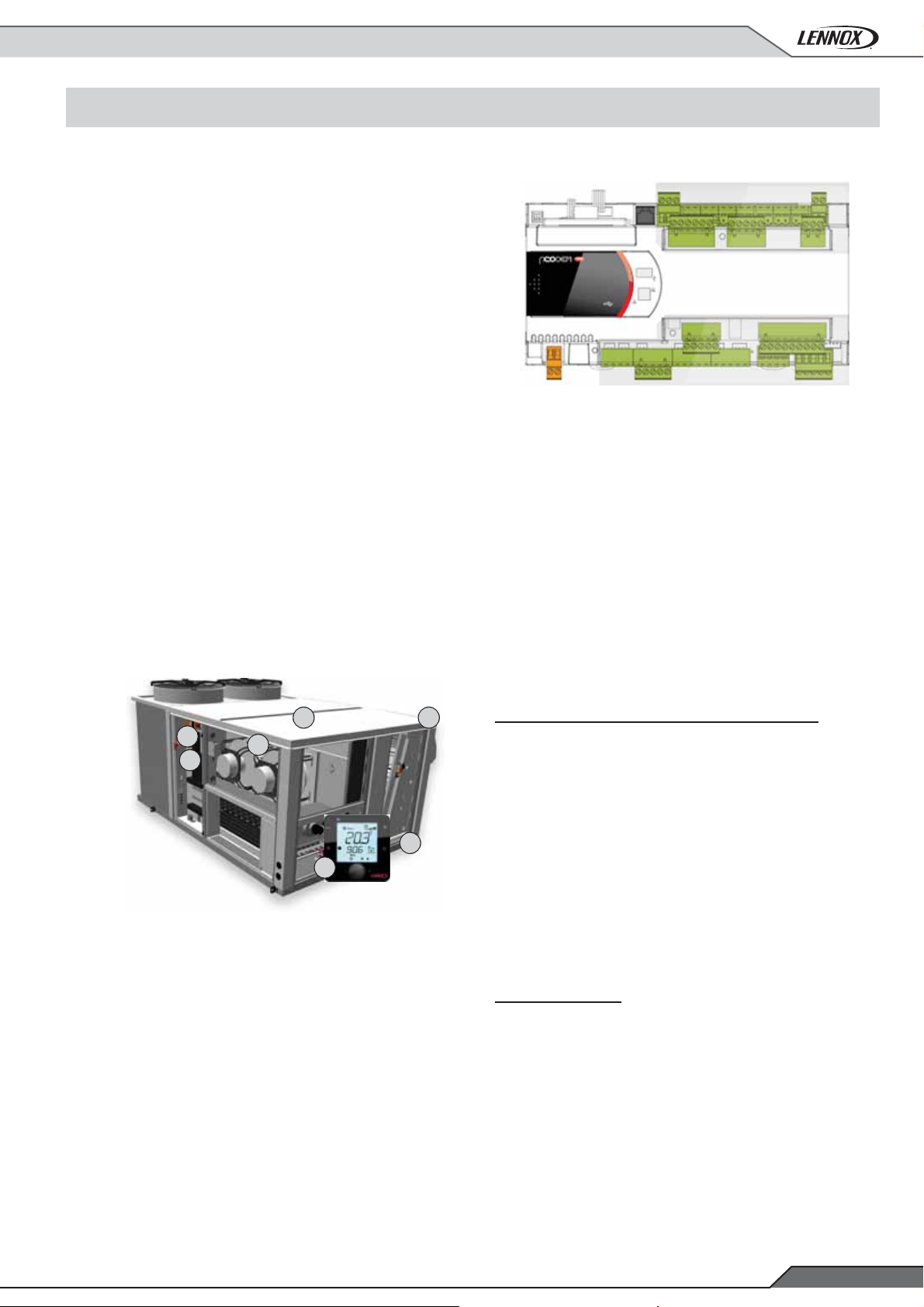
eClimatic ADVANCED CONTROLLER
eClimatic is the new generation controller that improves effi ciency
and helps set up and service operations to guarantees long
lasting performance
1.2. CASING
FLEXAIR indoor section is built with precoated galvanized steel
panels painted in RAL 9003 color, specially designed for corrosion
resistance and to ensure long operation life time.
Double skin can be demanded as an option.
Condensing section mounted in a rigid base frame to ensure
good support for compressors and giving rigidity to the complete
structure.
1.3. ADVANCED REFRIGERANT
CIRCUIT
FLEXAIR presents the most advanced design in the refrigerant
pipes, optimizing pipe length and at the same time giving the
best access for service and maintenance operations.
The exchangers have been specially designed by Lennox for
R410A operation, this copper tube and aluminum fi ns exchangers
have been tested to give the best heat transfer and the best
energy ratios.
The refrigeration circuit is responsible for up to 40% of the annual
energy consumption of a typical packaged air conditioning unit.
FLEXAIR features high effi ciency, environmentally friendly
refrigeration circuits with multiscroll R410A compressors,
electronic expansion valves and optimized heat exchange
surface area.
HEAT RECOVERY SOLUTIONS
FLEXAIR range includes a heat recovery wheel to recovery
energy from the extraction air
This heat recovery wheel is fi tted in a separated module to be
installed on site
Application Guide /FLEXAIR-AGU-1505-E
• 5 •
Page 8

1- GENERAL DESCRIPTION
SAVING ENERGY WITH ADVANCED
REFRIGERATION CIRCUIT DESIGN
R410A refrigerant
Effi cient systems such as FLEXAIR are designed around R410A
refrigerant to achieve the best performances.
• Energy effi cient refrigerant thanks with pressure drop in the
pipes: Higher evaporating pressure and lower condensing
pressure improve compressor EER & COP.
• R410A compressors have a better isentropic effi ciency.
• Environmentally friendly refrigerant:
It contains No Chlorine (ODP =0). Signifi cant refrigerant charge
reduction (-40%) that limits the global warming potential of the
system. R410A optimized heat exchangers use less material
(copper, aluminum …)
1.4. MULTISCROLL COMPRESSOR
TECHNOLOGY
FLEXAIR units are provided with tandem compressors, to profi t
from the multiscroll compressor technology and giving the highest
seasonal performance and the best SEER coeffi cients.
High effi ciency multiscroll technology
Air conditioning equipments are sized to cover the need for the
most critical weather conditions which most likely will occur only
a few days or even a few hours during the year.
Most of the time, in Europe, the external temperature drops below
the reference value and consequently systems usually run 96%
of the time at part load. It is therefore important to design system
around part load performance to achieve the lowest possible
annual energy consumption.
FLEXAIR provides high effi ciency and best possible part load
effi ciencies year round with high effi ciency multiscroll R410A
compressor technology.
Evolution of the net EER with varying capacity load
Net EER
4,5
4,0
3,5
3,0
2,5
MultiScroll + eDrive
A
MultiScroll
Inverter Scroll
B
C
TM
Single Scroll
2,0
1,5
A Multiscroll + eDRIVE C Multiscroll
B Inverter scroll D Single scroll
Source: PERSAPAC Study by Cetiat, Eurovent, Armine & EDF
Lennox Europe Laboratory comparative testing on rooftops
D
10 20 30 40 50 60 70 80 90 100
Capacity load in % of nominal
• 6 •
Application Guide / FLEXAIR-AGU-1505-E
Page 9

1- GENERAL DESCRIPTION
Multiscroll” compressor technology with electronic expansion
valves allows energy consumption reduction when compared
to “inverter” solutions:
• Multiscroll compressors are always running at their best
nominal operating conditions whereas compressors with
inverter control usually run at 90 Hz for nominal point down
to 30 Hz for low capacities.
• Energy consumption due to inverter electronics for speed
variation can reduce effi ciency by up to 5%.
• Multiscroll compressor assemblies optimize heat exchanger
usage during part load operation. For example, with 50%
capacity load, a FLEXAIR would only start one compressor
on each circuit. The running compressors would then benefi t
from the whole heat exchange surface area and the whole
airfl ow rate: The EER is then increased to 4.5 in some cases.
• Multiscroll compressor assemblies improve operating limits
giving the possibility to unload compressors providing cooling
to the building even when the outdoor temperatures are very
high. With unloading, FLEXAIR can operate and supply
cooling operating one compressor with outdoor temperatures
reaching 50°C.
1.5. ELECTRONIC EXPANSION
VALVES
The new electronic expansion valves are directly driven by the
eClimatic and optimize the performances in both cooling and
heating mode and provide reliable and accurate operation in all
conditions all year round.
This model of electronic expansion valves ensures also smooth
and precise control at low capacities for improved part load
performances.
Application Guide /FLEXAIR-AGU-1505-E
• 7 •
Page 10

1- GENERAL DESCRIPTION
1.6- EC FANS IN SUPPLY AND EXTRACTION
EC fan technology offers the maximum effi ciency together with
the minimum power consumption. That’s why FLEXAIR provides
EC fans both in indoor and exhaust section.
FLEXAIR will adapt the fan pressure to the different conditions
of the unit, and will provide high pressure available in the duct
even when all the options have been selected.
The EC plug-fan technology allows:
- Adapting airfl ow at commissioning
- Varying airfl ow during unit operation providing progressive
infl ation of smooth /textile ductworks
- Easy maintenance operations, as there is not pulleys and
belts regulation
eClimatic profi ts about this EC technology by:
- Monitoring the airfl ow in the service terminal
- Compensating the airfl ow if the fi lters are dirty
- Regulating the airfl ow to arrive to the desired set point tem-
perature.
Optimize the air-fl ow to the load demand (reduce consumption
when possible)
2
3
Annual compressor consumption
1
Annual consumption of other electical systems
2
Remaining annual fan motor consumption
3
Energy savings thanks to eDRIVE
4
4
1
40 %
18 %
12 %
30 %
VARIABLE SPEED DRIVE
Airfl ow reduction during part load operation and dead zone can
help save on energy consumption.
Condensing section mounted in a rigid base frame to ensure
good support for compressors and giving rigidity to the complete
structure.
eDRIVE
VENTILATION
eDRIVE is a standard feature
of Lennox FLEXAIR units
for ventilation with direct
transmission, variable speed
drives that saves energy and
reduces maintenance costs.
SAVING ENERGY WITH eDRIVE VARIABLE
SPEED, DIRECT DRIVE FAN.
With a rooftop, the blower fan motor is one of the major contributors
to annual energy consumption. Fans usually run 97% of the year
at full speed to circulate the air inside the building. 42% of the
annual energy consumption of an air conditioner is due to the
fan motor, which can be more than compressors.
There is no need to reduce airfl ow rate too much to achieve
important energy savings: For example reducing airfl ow rate by
only 25% will save 60% on the fan motor energy usage.
Fan absorbed power with variable airfl ow rate
(% of nominal)
Fan absorbed power
Airfl ow rate
(% of nominal)
• FLEXAIR integrates the new eDRIVE which automatically
adjust airfl ow rate to the needs, saving up to 30% annual
rooftop energy consumption.
• Airfl ow Rate can be easily adjusted to the exact needs, thanks
to eFlow the airfl ow measurement and display system.
• eDRIVE will correct power factor to reduce current.
• eDRIVE integrates soft starter feature as standard, that will
reduce inrush current during fan starts and makes the unit
fully compatible with fl exible ducts air diffusion systems.
- 25%
• 8 •
Application Guide / FLEXAIR-AGU-1505-E
Page 11
1- GENERAL DESCRIPTION
1.7- eCLIMATIC NEW CONTROL
Our FLEXAIR range includes our New e-climatic control
generation.The main features of this control are :
- Plastic cover to protect the circuit board from water entry
and humidity and with all the different connection terminals
correctly identifi ed.
- Two independent buses, one for display and sensors connection and another one for internal components.
- Possibility of storing all parameterized conditions before an
alarm is produced.
- Stronger hardware thanks to the plastic cover which protects
the circuit board from water entry and humidity (and at the
same time clearly identify all the different connection terminals)
- More reliable hardware thanks to the different communication buses for internal/main devices (compressors, fans,
etc.) and for the remote/accessory ones (display, probes),
which preserve the regular unit operation even in case of
commissioning miswirings
- Enhanced ClimaticTM regulation thanks to the better embedded processor and to the new Universal I/O chip, which
allows to match better contacts, probes and relays to the
controller board.
- Internal log memory to record unit operating trends (e.g.
temperatures before alarm occurrence).
OPTIMIZED OPERATION AND SETUP
SAVES ENERGY
Three different platforms are available :
● End customer display DC: with basic confi gurations, set
points, main temperature readings and alarms.
● Multiple display DM: graphic customer display with basic
confi guration of the end customer display plus schedule
programming and set of fresh air %.
● Service display DS: Specially focused to maint
4
6
5
2
7
3
1
eClimatic is designed to provide the best effi ciency throughout
unit’s lifecycle while ensuring reliable and consistent operation
with user-friendly interfaces .This controller monitories more
machine parameters than ever to improve energy effi ciency
and reliability
1 Indoor air temperature (humidity and CO2 levels as an option )
2 Outdoor air temperature (outdoor humidity as an option )
3 Return and supply air temperature
4 Filter pressure drop
5 Airfl ow rate with eFlow
Refrigeration circuit effi ciency management
Climatic control regulation
The Climatic controls the blowing air temperature to achieve the
customer comfort in the most effi cient way, matching perfetctly
the cooling/heating load with the optimum unit capacity staging
(multiscroll compressors, heat recovery modules, freecooling,
gas burners, water coils, etc.).
The unit reliability is ensured by a complete set of protections as
compressor envelop control, air-fl ow and pressure drops check,
advanced refrigerant leakage detection, compressor anti short
cycling rules.
All these fetaures are designed to optimize the unit performance,
but at the same time to increase its life-time and make easier
its maintenance.
Dynamic defrost:
It is a standard feature of all Lennox heat pumps. It limits the
number and the duration of the defrost cycles in winter to maximize
COP. With a smart and propietary frost-detection system, the
lennox rooftops autumatically optimize the number and the
durantion of the defrost cycles to get the best units perfonces
in every enviromental conditions.
6 Refrigerant pressures, temperatures & compressor monitoring
7 Power energy metering (option )
Application Guide /FLEXAIR-AGU-1505-E
• 9 •
Page 12

1- GENERAL DESCRIPTION
Free cooling:
It is one of the most important features of this rooftop as it maximise
seasonal effi ciency by reducing the use of thermodynamic cooling
in mid season.
Intelligent fresh air management:
With accurate percentage of fresh air the dampers are regularly
calibrated to introduce just the required amount of fresh air in the
building to reduce annual energy consumption. The fresh air ratio
can also be controlled using the indoor CO2 level as an input.
Intelligent heating priority optimization:
This unique feature on the market, allows the user to program the
priority between the different heating elements (thermodynamic,
electric pre-heaters or auxiliary heating). This is particularly
interesting on dual fuel units or units with electrical pre-heaters.
This feature maximizes energy effi ciency by optimizing heat pump
operation depending on the outdoor temperature.
Full Scheduling
Impressive energy savings can be done with a proper timescheduling that optimizes the unit operation to the different load
scenarios of each installation.
For that reason the Climatic offers a weekly-based calendar with
up to 7 time-bands per day and 4 pre-set modes (Unoccupied,
Day, Day 1, Day 2).
For each of this pre-set modes, plenty of unit settings can be
optimized to the different moments of the day, for example during
the unoccupancy periods the comforrt setpoints could be relaxed,
during the energy-cost peaks hours the hot water coils or gas
burners could be preferred to compressor or electrical heaters,
fresh-air introduction can be reduced to warm-up the building
before customer arrival, etc.
Morning anticipation and dynamic set point
The unit can be programmed to switch-on in the morning to reach
the occupied zone temperature set point just in time.
The rooftop will start heating the building at a different time in
the morning depending on the outdoor temperature: The lower
the outdoor temperature, the earlier the rooftop would start to
ensure that the set point is reached by the time the fi rst occupied
zone (Z1) is starting. This is to avoid early start when outdoor
temperature is mild.
Example for a unit programmed to anticipate morning switch-on
if outdoor temperature is below 10°C at a rate of 10 minutes/°C.
Start time
Z1 = 08h00
Actual switch-on
Z1 = 07h30
Actual temp.
Dynamic set point can be used in summer to offset the ambient
temperature set point according to the outdoor temperature.
This is to avoid large temperature difference between indoor and
outdoor. The indoor temperature set point would then increase
with the outdoor temperature improving comfort and saving large
amount of energy.
Gradient : 10 min / °C
7°C
10°C
10°C
1 2
Unoccupied mode Day mode
3 4
Day1 additionnal mode Day2 additionnal mode
Communication and unit interlink
Master/slave or cascade control is a standard feature of the
FLEXAIR units. It can be used to connect up to 24 rooftops.
The units can then be programmed to optimize effi ciency and
improve reliability following 6 different strategies
Multi rooftops regulation
In case of multi-rooftop installations, The Climatic control of each
unit can improve the unit synergies and optimize the total airconditioning performance, without any additional cost or external
dedicated "Building Manager System", but just linking the units
together (up to 8) in the same network and appling any of the
following smart strategies::
1: Master Slave "total":
The master gives the ventilation order, its set point and its room
temperature/humidity/CO2 to all other rooftops.
2: Master Slave "temperature":
The master gives the ventilation order and its room temperature/
humidity/CO2 to all other rooftops, but they have their own set
point.
• 10 •
Application Guide / FLEXAIR-AGU-1505-E
Page 13

1- GENERAL DESCRIPTION
3: Master Slave "average":
The master gives the ventilation order and the room temperature/
humidity/CO2 used by all rooftop is the average of all rooftop,
each rooftop has its own set point.
4: Master Slave "cooling/heating":
All rooftop are stand-alone but the slaves have to have the same
running mode as the master (Cooling or heating).
5: Master Slave “Back-up”:
One rooftop is the back-up unit and will operate if any of the
other rooftops is stopped due to a major problem.
6: Rolling Back-up mode:
Same as above, except the "back-up" unit will change once a
week on Tuesday.
Note that, the outside temperature/humidity/CO2 given to all
rooftops can either be the average of all unit connected or the
external humidity/temperature of the master, allowing the use
of a single "weather station" for the whole site.
Faults and alarms
eCLIMATIC manages more than 90 different faults and alarms
codes and can store the last 32 with time and date. The stored
faults and alarms can then be displayed on the DS service
display and on the communication bus with the full text detail.
1.8. CONSTRUCTION, INSTALLATION
AND SERVICE
UNIT CONSTRUCTION
FLEXAIR by Lennox is assembled with the highest standards
of quality.
FLEXAIR units comply with the PED 97-23 and EN 60204
standard. It is manufactured in ISO 9001 and ISO 14001 factories.
This construction guarantees high corrosion resistance and lower
the weight impact, also ensuring that the air leakages are reduced
to the minimum. To improve the resistance to anticorrosion, the
panels are prepainted in RAL 9003.
TRANSPORT AND HANDLING
To facilitate handling of the
unit and minimize the risk of
damage, FLEXAIR units are
provided with lifting lugs located
in the base frame of the unit.
For transport and handling,
the units are wrapped in a
retractable plastic protection
PLUG AND PLAY UNIT
All options are factory installed on the unit, which means that
they are ready for use, optimizing the time spent on site for the
installation. Bottom entry (through the base) for electrical power
and hot water (if option fi tted) lines are available as standard.
To make installation easier, FLEXAIR power supply does not
require "neutral" connection. It is powered by 400 V, 3 phases,
50 Hz.
Circuit breakers
To improve safety and extend life time, circuit breakers protect
against over-loading, over current and a disconnected supply
phase. Maintenance is also improved as there is no requirement to
change fuses. The electrical panel is manufactured in accordance
with EN60204 electrical directive.
Numbered wires
All wires and connectors are numbered as shown on the electrical
drawing to facilitate maintenance and diagnostic
Main disconnect switch
The main switch is used as an emergency cut off.
It is mandatory to guarantee a proper accessibility to this switch.
Specifi c footbridges must be installed if the machine environment
is requiring it.
Main disconnect switch is lockable to increase safety around
the rooftop unit.
Switching off the unit with the disconnect switch will reset all.
Disconnect switch will be sized accordingly to the options picked
with the unit.
Application Guide /FLEXAIR-AGU-1505-E
• 11 •
Page 14

1- GENERAL DESCRIPTION
EASY ACCESS TO THE UNIT
COMPONENTS
In FLEXAIR we keep the accessibility of all the components to
the indoor unit, as well as all the internal refrigerant components
1.9. INDOOR AIR QUALITY
FILTERS
As standard the unit comes with EU3 fi lters
We can increase the capacity of fi ltration with an option of G4 and
an option of G4+ F7, to arrive offering an average arrestance of
synthetic dust above 90% (according to EN779:2012).
DOUBLE SKIN PANEL
As an option, indoor unit of FLEXAIR, can be provided by a
double skin panel, to avoid the carrying of insulation particles
inside the building (25mm of thickness).
EC FANS VENTILATION SISTEM
FLEXAIR is fi tted with EC fans as standard, ensuring that no
belt particles can be carried away into building .This ventilation
system is compliant with EN 13977 air quality norm.
ANALOGUE FILTER DETECTION
Thanks to this sensor, the fi lter presence and the proper fan
operation is ensured by a pressure drop above the minimum
threshold, and at the same time the fi lter dirtyness is identifi ed
by a pressure drop above the maximum threshold.
REMOVABLE ALUMINIUM DRAIN PAN
All units are equipped with a sloped removable drain pan in
aluminum which can be removed for maintenance, preventing
the growth of bacteria an algae in the drain pan.
• 12 •
Application Guide / FLEXAIR-AGU-1505-E
Page 15

1- GENERAL DESCRIPTION
1.10- FRESH AIR AND FREE COOLING SYSTEM
Freecooling system is a standard feature for all Lennox rooftops,
with a two sections damper made in aluminum, and connected with
a proportional servomotor commanded by the control e-climatic
.
New buildings that comply with EPBD will have good thermal
insulation with high internal loads and will require cooling even
when outdoor temperatures are low.
Managing fresh air is mandatory in a building to control CO2
level and comfort.
Fresh air management and Free Cooling are standard features
of FLEXAIR that can reduce annual energy consumption.
SAVING ENERGY WITH FRESH AIR
& FREE COOLING
• Thermodynamic cooling can be replaced by Free Cooling
when outdoor temperature is below the building set point
saving up to 15% on annual energy consumption.
• Introducing just the required amount of Fresh Air in a building
can reduce energy consumption.
Because a fresh air damper curve is not linear, it is not accurate
to assume that the percentage of opening of the damper is equal
to the percentage of fresh air entering the building. However, this
linear control of a damper is by far the most used in the industry
With Indoor air quality and running cost of a building being more
important to our customer, FLEXAIR can manage the percentage
of fresh air more accurately.
100
90
80
70
60
50
40
30
20
10
Fresh air rate in % of supply airfl ow
Curve А : ΔP return ducts > Fresh air: Too much fresh air
Curve B : ΔP return ducts < Fresh air: Not enough fresh air
10 20 30 40 50 60 70 80 90 100
% Damper position
A
B
I
f the pressure drop in return air duct is high, the amount of fresh
air actually introduced in the building can be higher than required.
This extra fresh air will have to be cooled in summer and heated
in winter, increasing energy consumption of the system.
FLEXAIR will periodically recalibrates fresh air dampers to ensure
just the required amount of fresh air is introduced in the building.
This recalibration is achieved using the return air, outdoor air
and supply air sensors.
Application Guide /FLEXAIR-AGU-1505-E
• 13 •
Page 16
2- OPTIONS DESCRIPTION
2.1- AUXILIARY HEATING OPTIONS
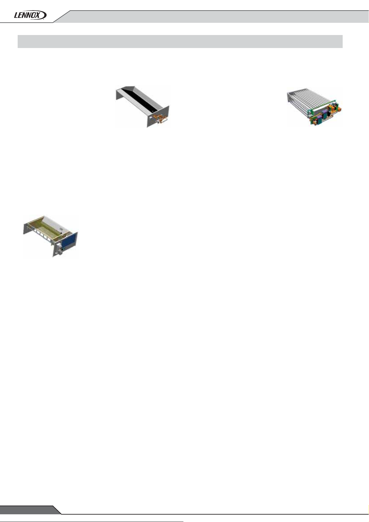
HOT WATER COILS
A water coil made of copper pipe and
aluminum fi ns can be installed to answer
heating requirements. This water coil
can, for example, be connected to a
boiler or a heat pump. Two sizes of
water coils are proposed to cope with
the cooling and heating requirements.
The water coil is equipped with a 3-way
valve.
To check the different capacities of the water coils, please
refer to the section "Heating auxiliary performances" of this
application guide.
The hot water coil are protected from freezing by the Climatic,
through low enviroment protections based on low supply and
external temperatures, which activates safety procedures lcve
pump starts, valve opening or return air damper opening.
ELECTRIC HEATER
The auxiliary electric heater is made
of shielded resistance heaters, which
are smooth 6 W/cm2 resistances.
The heater is protected against high
temperature with a thermal overload
protection set at 90°C 150mm after the
heating elements.
For any rooftop unit size, two sizes of
electric heater are available as option, S (standard) and H (high).
F Box: 85 to 120 Kw
Standard heat : 30 kW, 2 stages
Medium heat : 54 kW, fully modulating (Triac)
High heat : 72 kW, fully modulating (Triac)
GAS BURNER
FLEXAIR FAM and FAG units are
fi tted with a gas burner. It is a safe and
reliable atmospheric gas burner made
of aluminized steel tube heat exchanger
designed to offer maximum heat transfer
and 92% effi ciency (PCI%).
It runs with natural gas 20 mbar and an
operating range of 13-26 mbar.
The standard gas module offers 2 stages
of control which helps in improving space comfort by avoiding
large supply air temperature deviations. Where more capacity
control is required a modulating version is available with high
heat burner models. With the modulating gas burner the airfl ow
rate in the burner is controlled as the gas fl ow is being reduced
maintaining the burner to its highest effi ciency level.
If required, an expansion device can be provided with the unit
allowing it to operate with gas pressures of up to 300 mbar.
Gas fi red rooftop cannot be installed inside a technical room.
F Box: 85 to 120 Kw
Standard heat (two stages): 60 kW
High heat (modulating): 120 kW
G Box: 150 and 170 kW
Standard heat (two stages): 120 kW
High heat (modulating): 180 kW
H Box: 200 and 230 kW
Standard heat (two stages) : 180 kW
High heat (modulating): 240 kW
G Box: 150 and 170 kW
Standard heat : 45 kW, 2 stages
Medium heat : 72 kW, fully modulating (Triac)
High heat : 108 kW, fully modulating (Triac)
H Box: 200 and 230 kW
Standard heat : 72 kW, 2 stages
Medium heat : 108 kW, fully modulating (Triac)
High heat : 162 kW, fully modulating (Triac)
• 14 •
Application Guide / FLEXAIR-AGU-1505-E
Page 17

2- OPTIONS DESCRIPTION
2.2- HEAT RECOVERY OPTIONS
FLEXAIR RECOVERY ON EXHAUST AIR (HEAT RECOVERY WHEEL)
To match Lennox commitment to a greener planet and to generate FLEXAIR savings FLEXAIR by Lennox can be equipped with one
system to recover FLEXAIR from the extraction air.
Ideal for climates in which the difference between the outdoor temperature and the extraction air temperature is high. This new hybrid
rotary wheel will generate very high sensible but also latent transfer.
Fresh air entry is protected with G4 fi lter.
2.3- FILTRATION OPTIONS
FLEXAIR offer several different levels of fi ltration that will allow
coping with every application and any level of fi ltration demanded
in the installation.
As standard the unit comes with EU3 fi lters
G4 fi lters, offered as standard can give an average arrestance of
synthetic dust above 90% (according to EN779:2012).
As an option, Lennox can offer :
- G4 50 mm metallic frame with replaceable media, for those
environments in which it is expected to change fi lters more
frequently than usual.
- G4 50 mm + F7 100 mm with 90% opacimetric effi ciency and
low pressure drop.
Application Guide /FLEXAIR-AGU-1505-E
• 15 •
Page 18
2- OPTIONS DESCRIPTION
2.4- ELECTRICAL OPTIONS
ENTHALPY CONTROL AND CO2 SENSOR
This option includes combined temperature and humidity
sensors, to ensure that the economizer does not use 100%
fresh air if the outside air has a higher enthalpy than the return
air.
The CO2 sensor A VOC (Volatile Organic Component) detects
the amount of CO2 in the ambient air between 0 and 2000PPM.
(This obviously varies depending upon space occupancy levels).
The VOC sensor sends a proportional signal (0-20mA) to the
controller which will modulate the fresh air.
This option is highly reccomended in commercial installations
like restaurants, shops, etc., where the CO2 level strongly varies
during the day (e.g. depending on the people occupancy). In these
installations in fact the energy savings coming form the correct
air-renewal air-fl ow management (depending on CO2 level) can
defi nitively pay back this sensor cost in a very short time.
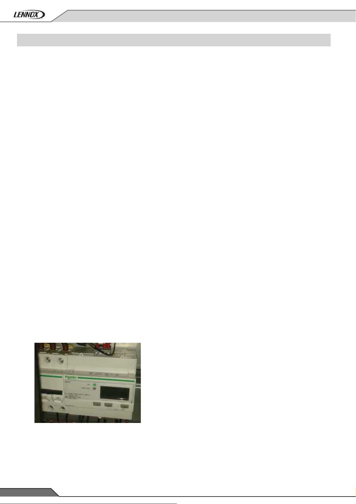
ENERGY METER
The FLEXAIR meter option is a device that measures and
displays the following parameters:
3 PHASE CONTROL
This phase control device offers the guarantee of the correct
phase connection, together with an overvoltage and under
voltage protection.
FIRE DETECTOR
It is a thermostat that provides a signal to switch off the unit,
close the fresh air damper and open the return damper when
the temperature in the return air stream is above an adjustable
set point (Factory setting: 70°C).
SMOKE DETECTOR
Located downstream of the fi lter, the optical head of the smoke
detector can detect any type of smoke. When this occurs the
unit will stop operating, the return air damper will be fully closed
and the fresh air damper will fully open while sending an alarm
signal to the unit.
In accordance with the European norm, it is also compliant with
the French regulation on public buildings.
• Average, total and maximum current, voltage and frequency
for each phase.
• Active & reactive power.
• Power factor (Cosφ).
• Total active & reactive FLEXAIR consumption in Wh.
Values for FLEXAIR, current and absorbed power can be reset
with password.
Some of these data will be collected by the controller and made
available in the BMS tables for Modbus, BACnet and Trend
protocols (not available for LonWorks).
• 16 •
Application Guide / FLEXAIR-AGU-1505-E
Page 19

2- OPTIONS DESCRIPTION
2.5- CONTROL OPTIONS
DC™ COMFORT DISPLAY
This is a remote controller for
non-technical customer. It is
designed to fi t aesthetically
inside a room and be very easy
to use. It has a 24V supply to
be connected to the rooftop and
can be installed at maximum
30 meters away from the unit.
The graphical display gives
information such as running
mode of the unit, status of the
fan, set point, % of fresh air,
outside air temperature.
Customer can set the temperature set point for a given time
zone, switch the unit “On” or “Off” and adjust the clock. DC can
display fault codes with a reset possibility, ambient, supply and
outdoor temperature, fresh air damper position (%), time zone
and operating mode pictogram, heating or cooling status.
It is also able to display supply fan airfl ow rate (0-33-66-100%)
and component status for compressors, defrost, condenser fans
and auxiliary heaters.
DC™ comfort display is equipped with a temperature sensor
that can be used as room temperature sensor.
DM™ MULTI-ROOFTOP DISPLAY
COMMUNICATION INTERFACES AND
SUPERVISION:
The CLIMATIC ModBus interface is required to connect the unit
to a BMS using "ModBus protocol". No other hardware than this
board is required to have ModBus communication. One board
required per rooftop. The ModBus interface is available in two
versions to be connected with RS485 or TCP/IP depending on
site requirements.
This board is also mandatory for any connection between one
or several FLEXAIR units and Lennox ADALINK II, Lennox
OneWeb, Lennox Cloud service 3G or LennoxVision supervision
solutions. One BMS interface required per rooftop.
ADALINK II™
Adalink II™ is Lennox’s simplest solution for HVAC installation
supervision to better control the system and improve reliability
and energy effi ciency. One ADALINK II™ can control up to 32
Lennox units on the same site (Chillers, rooftop or any other
unit using controller and above). It displays a site picture with
the status of each unit and allows the user to change set points,
access alarm history and plot charts. It is the ideal tool to save
time and money on maintenance with an expert mode giving
access to all the parameters and set point of the unit.
• Easy local management of important settings
• Possibility to create macro commands to simplify setting and
better control the installation
• Easy scheduling by unit or by zone with a smart user friendly
drag and drop system
• Preventive maintenance to reduce downtime and improve
comfort and energy effi ciency at all time.
• Remote connection via LAN or 3G
• Site maintenance planning
This display gives access to more functionality than the DCTM
and allows managing up to 8 rooftops on a single Bus-wire.
Customer will be able to change the operating time zone and
mode. The rooftops can be connected to operate on a Master/
Slave principle. Installation up to 1000m from the unit.
DS™ SERVICE DISPLAY
This new plug and play service display and controller allows
service personal to set up to read and modify all unit parameters
(Unit settings, operating time and number of compressor starts,
low and high pressure reading, airfl ow rate of supply fan, and
read the history of last 32 faults...).
This controller has been designed to be very user friendly, with
6 different keys and graphic display. It includes scrolling menus
and full text (no codes) explanation. It is available in English or
another alternate language.
ADALINK II™ can also act as a real gateway to the unit, as it can
be used locally or via LAN network with ModBus TCP/IP protocol.
Any BMS can read and write information in the rooftops units using
ADALINK II™ network. Both systems can run at the same time.
Application Guide /FLEXAIR-AGU-1505-E
• 17 •
Page 20

2- OPTIONS DESCRIPTION
2.6- REFRIGERATION OPTIONS
Low Noise Option
As rooftops are often installed in a noise sensitive area, LENNOX
proposes a low noise option on FLEXAIR. To achieve low noise
level, FLEXAIR receives a quieter fan, a compressor jacket and
is fully equipped with acoustic isolation in the refrigerating box.
2.7- FRESH AIR OPTIONS
As managing fresh air is becoming mandatory in most buildings
economiser is now fi tted as standard with the FLEXAIR.
Advanced control pack
Where a higher level of controllability is required to make the
FLEXAIR even more fl exible, LENNOX have compiled a pack
that includes two advanced control features.
• "Enthalpy control on economiser".
The eCLIMATIC and its humidity sensors (return air and fresh
air) ensures that the economiser does not use 100% fresh
air if the outside air has a higher enthalpy than the return air.
This feature is relevant in regions where the relative humidity
is high or when the desired room air condition is very dry.
Anti corrosion protection
When the units are installed in potentially aggressive
environments, which can often be the case for example in coastal
environments, it is often a requirement that the coils are specially
treated to protect them against the corrosive effects.
LenGuard™ anti-corrosion treatment is available for condensers,
evaporators and hot water coil.
Indoor air quality sensor
Indoor air quality is controlled from the eCLIMATIC main
controller. A VOC (Volatile Organic Component) sensor detects
the amount of CO2 in the ambient air between 0 and 2000PPM.
(This obviously varies depending upon space occupancy levels).
The VOC sensor sends a proportional signal (0-20mA) to the
eCLIMATIC controller which will then modulate the fresh air.
• "Humidity control"
The eCLIMATIC and its humidity sensors, analyze dry and
wet bulb temperatures to control dehumidifi cation. Humidity
control is only available if ambient temperature is in cooling
or dead zone. The dehumidifi cation algorithm can dry the air
by passing it through the coil in cooling mode.
A specifi c function in the program can be activated to control
the minimum supply air temperature, by maintaining it equal
to the heating set point, using auxiliary heaters (Electric, Hot
water coil or gas burner).
A proportional 0-10V contact is also available to control an
external humidifi er.
• 18 •
Application Guide / FLEXAIR-AGU-1505-E
Page 21

2- OPTIONS DESCRIPTION
2.8- AIRFLOW CONFIGURATIONS AND ROOFCURBS
BASIC AIRFLOW CONFIGURATIONS
Standard
Unless specifi ed otherwise when ordered, FLEXAIR rooftops
are shipped with downfl ow supply and return confi guration.
Units can be confi gured before shipment with the required
airfl ow confi gurations to suit the building needs.
AIR SOCK CONTROL
A standard feature in FLEXAIR, EC fan regulation allow the air
socks to be progressively fi lled with air on start up. It takes one
minute to go from 0% of air to Nominal airfl ow rate
ROOFCURBS
Non adjustable non assembled roofcurb.
A sturdy mounting frame designed for single package units
providing an automatic weatherproof sealed rooftop installation.
This roofcurb is shipped knocked down and must be assembled
on site.
Adjustable roofcurb.
This adjustable and assembled roofcurb is made of galvanized
steel with 2.5 mm. This adjustable roofcurb is designed to be
installed in roofs with slopes up to 4 to 5% in all directions,
enabling FLEXAIR to be compatible with most roof profi les.
Downfl ow roofcurbs are the easiest and the cheapest way to install
packaged air conditioning systems to a single volume building.
The frame can be secured directly to the roof structure thanks
to its built in adjustable fl anges and sealing liner returns
Multidirectional roofcurb
This option is a required when customer wants to have horizontal
return and horizontal supply on the same side.
It is also required with the power exhaust fan or gravity exhaust
damper options combined with horizontal return fl ow confi guration.
5%
Rooftop
Roofcurb
Thermal insulation
5%
50
Sealing
400 mm minimum
Application Guide /FLEXAIR-AGU-1505-E
• 19 •
Page 22

2- OPTIONS DESCRIPTION
2.9- EXTRACTION OPTIONS
UNIT WITH NO EXHAUST AIR OPTION
1 → 2 : ESP (external static pressure) given in eLencal (LENNOX
units selection tool) corresponds to the static pressure between
inlet and outlet of the unit and includes all options and accessories
delivered with the unit with the exception of the ductwork. This
external static pressure will be used to push the air through the
supply and the return ductwork installed on site.
ESP =
Supply duct pressure drop + return duct pressure drop
Example :
With an eLencal ESP = 350 Pa and a return ductwork pressure
drop of 150 Pa ▬► Remaining available static pressure for the
supply ductwork = 200 Pa
In any case, on a basic unit, the return ductwork pressure drop
should be lower than 150 Pa.
The airfl ow is usually set during start up for a given fresh air
rate. During normal operation the fresh air ratio will change and
eventually the unit will go to full fresh air during free cooling
operation. If the pressure drop in the return ductwork is high,
the fan may trip on over current protection when it operates with
full fresh air where the pressure drop is much lower.
If the return ductwork pressure drop is higher than 150 Pa :
• Select an extraction roofcurb which will include an extraction
fan and the appropriate drive kit for the given airfl ow and
pressure drop.
• FLEXAIR with eDRIVE includes constant airfl ow operation
that can control and limit the airfl ow as the pressure drop
reduces.
Building air tightness Low air tightness
Fresh air & Free cooling
Pressure drop in the
return ductwork
Medium fresh air rate
Free cooling possible
Medium < 150 Pa
2
1
GRAVITY EXHAUST DAMPER
1 → 2: ESP “Supply” in eLencal
Gravity exhaust dampers are used to relief pressure when outside
air is being introduced in a building with good air tightness.
Building air tightness Medium
Fresh air & Free cooling
Pressure drop in the
return ductwork
Building pressure control Low control
Typical applications Warehouses
High fresh air rate
Free cooling
Low < 50 Pa
Building pressure control NO control
Typical applications
• 20 •
Existing hypermarkets and supermarkets
(old buildings with high leakage rates)
2
Application Guide / FLEXAIR-AGU-1505-E
1
Page 23

2- OPTIONS DESCRIPTION
POWER EXHAUST FAN
1 → 2: ESP “Supply” in eLencal.
Power exhaust axial fans with gravity exhaust dampers provide
exhaust air pressure relief when high levels of outside air are
being introduced in the building with good air tightness.
It is interlocked to run when return air dampers are being closed
and supply air blower is in operation. The power exhaust fan runs
when outdoor air dampers are at least 50% open (adjustable
by set point). It is also overload protected. A gravity exhaust
damper is supplied with this option to prevent air from entering
the unit when fan is off.
Building air tightness Medium
Fresh air & Free cooling
Pressure drop in the
return ductwork
Building pressure control Low control
High fresh air rate
Free cooling
Medium 50 Pa to 150 Pa
EXTRACTION ROOFCURB
1 → 3: ESP Return in eLencal
3 → 2: ESP Supply in eLencal
Where system balancing is critical and return ductwork pressure
drop is high, it is recommended to use extraction fan such as
the one located in the extraction roofcurb.
A plug fan installed with a 3rd damper (1 inside the Roofcurb
+ 2 inside the rooftop), is able to extract up to 300 Pa with the
Nominal airfl ow rate of the unit. This roof curb can be used in
either horizontal or downfl ow applications.
Building air tightness High
Fresh air & Free cooling
Pressure drop in the
return ductwork
Building pressure control Pressure balance possible
High fresh air rate
Free cooling
High > 150 Pa
Typical applications Light commercial, petrol stations...
2
1
Typical applications
Theatres, cinemas, data centres, new air
tight buildings with long return ductworks
Application Guide /FLEXAIR-AGU-1505-E
21
• 21 •
Page 24

3- GENERAL DATA
FAC FAH
Cooling only Heat pump
FAG FAM
Cooling only with gas fi red heating Heat pump rooftop with gas fi red heating
FLEXAIR 085 100 120
Casing F BOX
3
Nominal airfl ow rate m
Cooling mode (FAC - FAG)
Gross cooling capacity
(1)
Compressor gross power input
Indoor fan absorbed power
Full load amps
(1)
FAC 2,71 4,08 5,28
FAG 3,26 5,14 6,65
Direct start up amps ratio Id/Ia
Gross EER
Global net EER
(2)
(3)
Cooling mode (FAH - FAM)
Gross cooling capacity
(1)
Compressor gross power input
Indoor fan absorbed power
Gross EER
Global net EER
(2)
(3)
FAH 2,71 4,08 5,28
FAM 3,26 5,14 6,65
Heating mode (FAH - FAM)
Net heating capacity
FAH 78,4 94,7 109,0
Compressor gross power input
Indoor fan absorbed power
Gross COP
Global net COP
(2)
(3)
FAH 2,71 4,08 5,28
FAM 3,26 5,14 6,65
Heating - Gas fi red
(4)
Heating capacity kW
Power input kW
S
(4)
H
(4)
S
(4)
H
Thermal effi ciency %
(4)
Gas fl ow (for natural gas at 20 mbar and 15 °C) m
S
(4)
H
Refrigeration circuit
Number of circuits
Compressor type and number
Expansion valve number
Refrigerant charge per circuit 1/2 kg
FAC-FAG
FAH-FAM
Ventilation data
Nominal airfl ow rate
Maximum airfl ow rate
External static pressure / Maximum
(1) All data are at Eurovent conditions (400V/3Ph/50Hz at nominal airfl ow rate),
nominal external static pressure.
Cooling :
• Outdoor temperature = 35°C DB
• Entering coil temperature 27°C DB / 19°C WB
Heating :
• Outdoor temperature = 7°C DB / 6°C WB
• Indoor temperature = 20°C DB
(5)
/h
15000 18500 20500
86,0 101,3 119,3
kW
A
20,1 27,1 31,4
67,5 75,5 103,2
209,3 252,3 293,9
FAC 3,56 3,30 3,29
FAC 3,24 2,92 2,85
FAG 3,15 2,80 2,73
85,0 100,0 117,5
kW
20,6 27,1 31,3
FAH 3,52 3,26 3,24
FAH 3,20 2,88 2,81
FAM 3,11 2,76 2,69
kW
18,3 22,9 28,6
FAH 3,60 3,58 3,26
FAH 3,39 3,32 3,01
FAM 3,34 3,24 2,94
55,2
110,4
60
120
92
3
/h
6,3
12,5
1 scroll + 1 scroll
2
9 / 9 9,1 / 9,1 9,1 / 9,1
9,1 / 9,1 9,2 / 9,2 9,2 / 9,2
15000 18500 20500
3
m
/hMinimum airfl ow rate
12000 14000 15000
23000 23000 23000
Pa
(2) Including compressor + outdoor axial fan + indoor centrifugal fan
(3) Net COP = Net cooling capacity/Total absorbed power
(4) S = Standard heat / H = High heat
(5) At nominal airfl ow rate
150 / 800 150 / 800 150 / 800
• 22 •
Application Guide / FLEXAIR-AGU-1505-E
Page 25

3.- GENERAL DATA
FAC FAH
Cooling only Heat pump
FAG FAM
Cooling only with gas fi red heating Heat pump rooftop with gas fi red heating
FLEXAIR 085 100 120
Indoor fan (FAG - FAM)
Nominal airfl ow rate
3
m
Maximum airfl ow rate
External static pressure / maximum Pa
Fan number
Outdoor fan (axial fan)
Number
Nominal airfl ow rate m
3
Motor power kW
Filter (standard)
Effi ciency / Filter class
Number of fi lters
Filter size
mm
Acoustic data (150 Pa)
Outdoor sound power
Standard unit
Outdoor sound power
Low noise unit
(1)
(1)
dB(A)
Indoor blower outlet sound power
/hMinimum airfl ow rate
/h
15000 18500 20500
12000 14000 15000
23000
150 / 800
2
2
35150 35150 44000
3,12 3,12 4,5
80-85% / G3
8
625 x 500 x 50
80,2 81,7 88,7
78,1 78,1 85,3
86,3 80,7 84,6
Operating limits - Cooling mode
Maxi. outdoor temperature
Indoor 27 °C DB / 19°C WB
(2)
Maxi. outdoor temperature with unloading
Mini. outdoor temperature
Indoor 20°C DB
(3)
Maxi. outdoor temperature
DB/WB with 100% fresh air
°C
48
50
10
38
Operating limits - Heating mode
Mini. outdoor temperature
Indoor 20 °C DB
(2)
Mini. entering indoor coil temperature
Outdoor 7°C DB
°CMini. outdoor temperature with unloading
-15
-15
7
Construction
Casing material Aluminium
Painting Polyester / RAL 9003
Insulation class
A2-s1-d0 / M0
Dimensions
Length
Height
Width with/without fresh air hood
Weight
Standard unit (FAC)
Weight
Gas unit (FAG-H)
(5)
mm
(4)
966 1055 1054
kg
1083 1187 1178
3348
1750
2290 / 2657
(1) All data are at Eurovent conditions (400V/3Ph/50Hz at nominal airfl ow rate),
nominal external static pressure.
Cooling :
• Outdoor temperature = 35°C DB
• Entering coil temperature 27°C DB / 19°C WB
Heating :
• Outdoor temperature = 7°C DB / 6°C WB
• Indoor temperature = 20°C DB
Application Guide /FLEXAIR-AGU-1505-E
(2) Cooling and heating operating limits are given for steady operation with
specifi c temperature conditions.
(3) Below this value, "Low ambient kit" option is required
(4) Down return air and down supply air confi gurations
(5) S = Standard heat / H = High heat
• 23 •
Page 26

3- GENERAL DATA
FAC FAH
Cooling only Heat pump
FAG FAM
Cooling only with gas fi red heating Heat pump rooftop with gas fi red heating
FLEXAIR™ 150 170 200 230
Casing G BOX H BOX
Nominal airfl ow rate m
Cooling mode (FAC - FAG)
Gross cooling capacity
(1)
Compressor gross power input
Indoor fan absorbed power
Full load amps
(1)
FAC 5,60 8,20 8,74 10,81
FAG 6,76 10,00 10,24 12,95
Direct start up amps ratio Id/Ia
Gross EER
Global net EER
(2)
(3)
Cooling mode (FAH - FAM)
Gross cooling capacity
(1)
Compressor gross power input
Indoor fan absorbed power
Gross EER
Global net EER
(2)
(3)
FAH 5,60 8,20 8,74 10,81
FAM 6,76 10,00 10,24 12,95
Heating mode (FAH - FAM)
Net heating capacity
Compressor gross power input
Indoor fan absorbed power
Gross COP
Global net COP
(2)
(3)
FAH
FAH 5,60 8,20 8,74 10,81
FAM 6,76 10,00 10,24 12,95
Heating - Gas fi red
Heating capacity kW
Power input kW
S
H
S
H
Thermal effi ciency %
Gas fl ow (for natural gas at 20 mbar and 15 °C) m
S
H
Refrigeration circuit
3
/h
28000 30000 35000 39000
147,2 164,6 190,8 230,7
kW
A
44,5 49,5 51,4 61,5
109,8 137,4 155,5 194,5
296,1 283,6 341,4 398,6
FAC 3,08 3,04 3,29 3,26
FAC 2,77 2,65 2,89 2,84
FAG 2,69 2,54 2,80 2,73
141,9 161,8 188,1 227,9
kW
44,3 49,4 51,4 61,5
FAH 2,98 3,00 3,24 3,22
FAH 2,68 2,61 2,85 2,80
FAM 2,60 2,50 2,76 2,70
133,7 155,5 185,2 223,8
kW
33,5 38,6 43,1 57,9
FAH 3,63 3,60 3,73 3,33
FAH 3,38 3,29 3,43 3,09
FAM 3,31 3,21 3,37 3,03
(4)
(4)
(4)
(4)
110,4 110,4 165,6 165,6
165,6 165,6 220,8 220,8
120 120 180 180
180 180 240 240
92 92 92 92
(4)
3
(4)
/h
12,5 12,5 18,8 18,8
18,8 18,8 25 25
Number of circuits
Compressor type and number
Expansion valve number
Refrigerant charge per circuit kg
FAC-FAG
FAH-FAM
Ventilation data
Nominal airfl ow rate
m
Maximum airfl ow rate
External static pressure / Maximum
(1) All data are at Eurovent conditions (400V/3Ph/50Hz at nominal airfl ow rate),
nominal external static pressure.
Cooling :
• Outdoor temperature = 35°C DB
• Entering coil temperature 27°C DB / 19°C WB
Heating :
• Outdoor temperature = 7°C DB / 6°C WB
• Indoor temperature = 20°C DB
(5)
• 24 •
1 scroll +
2 scroll
2 scroll + 2 scroll
2
14,7 / 14,2 14,7 / 14,3 18,5 / 18,5 19,8 / 19,8
15 / 14,5 15,1 / 14,5 18,5 / 18,5 19,8 / 19,8
28000 30000 35000 39000
3
18000 21000 24000 27000
/hMinimum airfl ow rate
35000 35000 43000 43000
Pa
(2) Including compressor + outdoor axial fan + indoor centrifugal fan
(3) Net COP = Net cooling capacity/Total absorbed power
(4) S = Standard heat / H = High heat
(5) At nominal airfl ow rate
150 / 800
Application Guide / FLEXAIR-AGU-1505-E
Page 27

3- GENERAL DATA
FAC FAH
Cooling only Heat pump
FAG FAM
Cooling only with gas fi red heating Heat pump rooftop with gas fi red heating
FLEXAIR™ 150 170 200 230
Indoor fan
Nominal airfl ow rate
Minimum airfl ow rate m
3
Maximum airfl ow rate
External static pressure / maximum
Pa 150 / 800
Fan number
Outdoor fan (axial fan)
Number
Nominal airfl ow rate m
3
Motor power kW
Filter (standard)
Effi ciency / Filter class
Number of fi lters
Filter size
mm
Acoustic data (150 Pa)
Outdoor sound power
Standard unit
Outdoor sound power
Low noise unit
(1)
(1)
dB(A)
Indoor blower outlet sound power
/h
/h
28000 30000 35000 39000
18000 21000 24000 27000
35000 35000 43000 43000
3
2244
38950 49400 69350 88000
2,96 4,16 6,24 8,96
80-85% / G3
12 12 10 + 5 10 + 5
625 x 500 x 50 500 x 500 + 800 x 500
87,3 91,6 85,0 89,1
84,9 88,6 82,2 88,6
92,8 83,8 92,5 96,5
Operating limits - Cooling mode
Maxi. outdoor temperature
Indoor 27 °C DB / 19°C WB
(2)
Maxi. outdoor temperature with unloading
Mini. outdoor temperature
Indoor 20°C DB
(3)
Maxi. outdoor temperature
DB/WB with 100% fresh air
°C
46 46 48 48
45
10
38
Operating limits - Heating mode
Mini. outdoor temperature
Indoor 20 °C DB
(2)
Mini. entering indoor coil temperature
Outdoor 7°C DB
°CMini. outdoor temperature with unloading
-15
-15
7
Construction
Casing material Aluminium
Painting Polyester / RAL 9003
Insulation class
A2-s1-d0 / M0
Dimensions
Length
Height
Width with/without fresh air hood
Weight
Standard unit (FAC)
Weight
Gas unit (FAG-H)
(5)
mm
(4)
kg
4385 4385 5230 5230
1885 1885 2235 2235
2290 / 2753
1454 1550 2027 2143
1599 1704 2297 2411
(1) All data are at Eurovent conditions (400V/3Ph/50Hz at nominal airfl ow rate),
nominal external static pressure.
Cooling :
• Outdoor temperature = 35°C DB
• Entering coil temperature 27°C DB / 19°C WB
Heating :
• Outdoor temperature = 7°C DB / 6°C WB
• Indoor temperature = 20°C DB
Application Guide /FLEXAIR-AGU-1505-E
(2) Cooling and heating operating limits are given for steady operation with
specifi c temperature conditions.
(3) Below this value, "Low ambient kit" option is required
(4) Down return air and down supply air confi gurations
(5) S = Standard heat / H = High heat
• 25 •
Page 28
4- OPTIONS DATA
FAC FAH
Cooling only Heat pump
FAG FAM
Cooling only with gas fi red heating Heat pump rooftop with gas fi red heating
FLEXAIR
Nominal airfl ow rate m3/h
085 100 120 150 170 200 230
15000 18500 20500 28000 30000 35000 39000
Heating - electric
Type of modulation m
S
Available heating capacity kW
M
H
Amps S / M / H
3
/h Staged on S / Triac on M & H
(2)
(2)
(2)
30 30 30 45 45 72 72
54 54 54 72 72 108 108
72 72 72 108 108 162 162
42/75/99 42/75/99 99/149/196
Heating - hot water coil
Available heating capacity
(2)
(1)
S
(2)
H
114 126 133 145 156 177 186
kW
177 201 212 254 275 295 313
Gas modulating
Modulation range
(2)
H
% 40-100 20-100
Axial exhaust fan
Number of fans
3
Heat recovery module
Type of exchanger Wheel exchanger
Protection against frosting on exhaust air Air differential pressure switch 20 to 300 Pa
Lenght
Height
mm
Width with/without fresh air hood
Weight kg
Wheel diameter mm
Number of fi lters
Fresh air / Return air
2146 2330 2516
1796 2170 2418
1422 / 1055 1518 / 1055 1676 / 623
525 635 730
1500 1800 2050
3 / 3 8 / 8 10 / 10
Filter G4 and G4+F7
Effi ciency (gravimetric) / class EN779 / Eurovent G4
90% / G4 / EU4
Effi ciency (opacimetric) / class EN779 / Eurovent F7
Number of fi lters
Filter size mm
8 12 10 + 5
625 x 500 x 50 625 x 500 x 50 500x500 + 800x500
Fire class
Power exhaust fan (axial fan)
Number of fans
Diameter
(1) Conditions : entering water temperature 90°C, leaving water temperature 70°C, entering air temperature 20°C,
S = standart heat, H = high heat
(2) not available with FAG and FAM versions
33
450 560
85% / F7 / EU7
M1
• 26 •
Application Guide / FLEXAIR-AGU-1505-E
Page 29

5- STANDARD UNITS PERFORMANCES
5.1- UNIT PERFORMANCES
FAC FAH
Cooling only Heat pump
COOLING CAPACITY AND ABSORBED POWER
FAH
Wet bulb Dry bulb
/h
3
12 000 m
Minimum airfl ow rate
/h
3
15 000 m
Nominal airfl ow rate
Entering air temperature
/h
3
23 000 m
Maximum airfl ow rate
Outdoor air temperature
16°C
19°C
22°C
16°C
19°C
22°C
16°C
19°C
22°C
21°C
24°C 81,3 65,2 17,0 78,1 63,7 18,7 74,5 62,0 20,7 70,4 60,1 22,9 65,9 58,0 25,3
27°C 82,2 77,0 17,0 79,0 75,6 18,8 75,4 74,0 20,7 71,4 71,3 23,0 67,4 67,4 25,5
30°C 85,1 85,1 17,1 82,4 82,4 18,9 79,2 79,2 21,0 75,5 75,5 23,2 71,4 71,4 25,8
24°C 88,1 52,6 17,4 84,6 50,9 19,1 80,6 49,2 21,1 76,1 47,4 23,2 71,2 45,6 25,7
27°C 88,8 64,9 17,4 85,3 63,3 19,1 81,3 61,6 21,1 76,8 59,7 23,3 71,8 57,7 25,8
30°C 89,7 76,7 17,5 86,2 75,3 19,2 82,2 73,6 21,2 77,7 71,8 23,4 72,7 69,5 25,8
33°C 90,8 88,1 17,5 87,3 86,9 19,3 83,9 83,9 21,3 80,1 80,1 23,5 75,7 75,7 26,1
27°C 96,1 52,2 17,8 92,1 50,3 19,6 87,7 48,5 21,5 82,8 46,8 23,7 77,5 45,1 26,3
30°C 96,7 64,4 17,9 92,8 62,7 19,6 88,4 61,0 21,6 83,5 59,2 23,8 78,2 57,3 26,3
33°C 97,6 76,1 17,9 93,7 74,6 19,7 89,3 73,0 21,6 84,4 71,2 23,9 79,1 69,2 26,4
36°C 98,7 87,3 18,0 94,8 86,1 19,7 90,4 84,7 21,7 85,5 82,9 23,9 80,2 80,2 26,5
21°C
24°C 85,2 73,2 17,2 81,8 71,6 19,0 78,0 69,9 20,9 73,6 67,8 23,1 68,9 65,5 25,5
27°C 86,4 86,4 17,3 83,5 83,5 19,1 80,1 80,1 21,1 76,3 76,3 23,3 72,1 72,1 25,8
30°C 91,4 91,4 17,6 88,3 88,3 19,4 84,8 84,8 21,4 80,9 80,9 23,6 76,4 76,4 26,1
24°C 92,0 58,1 17,6 88,2 56,4 19,3 83,9 54,7 21,3 79,2 52,9 23,4 74,0 51,0 25,9
27°C 92,9 72,9 17,7 89,1 71,2 19,4 84,8 69,5 21,3 80,1 67,5 23,5 74,9 65,3 26,0
30°C 94,0 87,4 17,7 90,2 85,8 19,5 85,9 84,0 21,4 81,1 81,1 23,6 76,6 76,6 26,1
33°C 96,8 96,9 17,9 93,6 93,6 19,7 89,8 89,8 21,7 85,6 85,6 23,9 80,9 81,0 26,5
27°C 100,0 57,5 18,1 95,8 55,7 19,8 91,2 53,9 21,7 86,1 52,2 23,9 80,5 50,4 26,5
30°C 100,9 72,4 18,1 96,7 70,7 19,8 92,1 68,9 21,8 86,9 67,0 24,0 81,3 64,9 26,5
33°C 102,0 86,8 18,2 97,8 85,2 19,9 93,1 83,5 21,9 88,0 81,5 24,1 82,4 79,1 26,6
36°C 103,3 100,8 18,3 99,0 99,0 20,0 95,0 95,0 22,0 90,6 90,6 24,3
21°C
24°C 91,9 91,8 17,6 88,2 88,2 19,3 84,2 84,1 21,3 79,6 79,6 23,5 74,6 74,6 26,0
27°C 97,3 97,3 17,9 93,5 93,5 19,6 89,3 89,3 21,6 84,6 84,6 23,8 79,4 79,4 26,4
30°C 103,1 103,1 18,2 99,2 99,2 20,0 94,8 94,8 22,0 90,0 90,0 24,3
24°C 98,6 70,7 18,0 94,2 69,0 19,7 89,2 67,3 21,6 83,8 65,4 23,8 78,0 63,2 26,3
27°C 100,0 92,4 18,1 95,6 90,5 19,8 90,6 88,4 21,7 85,0 85,0 23,9 79,7 79,8 26,4
30°C 103,4 103,4 18,2 99,4 99,4 20,0 94,9 94,9 22,0 90,0 90,0 24,2
33°C 109,2 109,3 18,6 105,1 105,1 20,4
27°C 106,9 69,8 18,5 102,1 68,2 20,2 96,8 66,5 22,1 91,0 64,7 24,3
30°C 108,3 92,0 18,5 103,5 90,1 20,3 98,2 88,1 22,2
33°C 109,7 109,7 18,6 105,4 105,5 20,4
36°C
25°C 30°C 35°C 40°C 45°C
PT PS PA PT PS PA PT PS PA PT PS PA PT PS PA
80,6 53,0 16,9 77,4 51,4 18,7 73,8 49,7 20,6 69,8 48,0 22,8 65,2 46,2 25,2
84,3 58,6 17,2 80,9 57,0 18,9 77,1 55,3 20,8 72,8 53,5 23,0 68,0 51,5 25,4
90,7 71,4 17,5 86,6 69,7 19,2 82,1 67,9 21,1 77,1 65,9 23,3 71,6 63,5 25,7
FAH
085
HEATING CAPACITY AND ABSORBED POWER
Outdoor air temp
FAH
/h
3
rate
12 000 m
Minimum airfl ow
/h
3
Dry bulb
15 000 m
Nominal airfl ow rate
Entering air temperature
/h
3
rate
23 000 m
Maximum airfl ow
PT :
Gross total cooling/heating capacity in kW
PS :
Sensible heating capacity in kW
PA :
Compressor absorbed power
xxx :
Data according to Eurovent standard conditions
8°C 108,9 18,3 97,2 17,3 97,2 17,3 80,2 15,7 76,2 15,4 67,0 14,5 58,6 13,7 51,0 13,0 48,2 12,7
11°C 107,3 19,4 95,8 18,3 95,8 18,3 79,1 16,7 75,2 16,3 66,2 15,4 58,0 14,6 50,6 13,9 47,9 13,6
14°C 105,6 20,5 94,3 19,4 94,3 19,4 78,0 17,6 74,2 17,2 65,4 16,3 57,4 15,5 50,2 14,8 47,6 14,5
17°C 103,9 21,7 92,8 20,5 92,8 20,5 76,8 18,7 73,1 18,3 64,5 17,3 56,7 16,4 49,8 15,7 47,3 15,5
20°C 102,1 23,0 91,3 21,7 91,3 21,7 75,6 19,8 72,0 19,4 63,6 18,3 56,1 17,4 49,3 16,7 46,9 16,5
23°C 100,3 24,4 89,7 23,0 89,7 23,0 74,3 21,0 70,8 20,5 62,7 19,4 55,3 18,5 48,8 17,7 46,4 17,5
26°C 98,5 26,0 88,1 24,4 88,1 24,4 73,1 22,2 69,7 21,7 61,7 20,5 54,6 19,5 48,3 18,8 46,0 18,5
8°C 111,0 17,1 99,0 16,2 99,0 16,2 81,5 14,8 77,5 14,4 68,0 13,7 59,4 12,9 51,5 12,3 48,6 12,0
11°C 109,3 18,0 97,6 17,1 97,6 17,1 80,5 15,6 76,5 15,3 67,3 14,5 58,8 13,7 51,2 13,1 48,4 12,9
14°C 107,7 19,0 96,1 18,0 96,1 18,0 79,4 16,5 75,5 16,1 66,5 15,3 58,2 14,6 50,8 13,9 48,1 13,7
17°C 106,0 20,1 94,6 19,0 94,6 19,0 78,2 17,4 74,5 17,1 65,6 16,2 57,6 15,5 50,4 14,8 47,8 14,6
20°C 104,2 21,2 93,1 20,1 93,1 20,1 77,1 18,4 73,4 18,1 64,7 17,2 56,9 16,4 50,0 15,8 47,4 15,6
23°C 102,5 22,4 91,6 21,2 91,6 21,2 75,8 19,5 72,2 19,1 63,8 18,2 56,2 17,4 49,5 16,8 47,0 16,6
26°C 100,7 23,7 90,0 22,5 90,0 22,5 74,6 20,6 71,1 20,2 62,9 19,2 55,5 18,4 49,0 17,8 46,6 17,6
8°C 114,7 15,2 102,1 14,5 102,1 14,5 83,6 13,3 79,3 13,1 69,2 12,4 59,9 11,8 51,4 11,3 48,2 11,1
11°C 113,2 16,0 100,7 15,2 100,7 15,2 82,6 14,1 78,4 13,8 68,5 13,2 59,4 12,6 51,1 12,1 48,0 11,9
14°C 111,6 16,8 99,4 16,0 99,4 16,0 81,6 14,9 77,4 14,6 67,7 14,0 58,9 13,4 50,8 13,0 47,8 12,8
17°C 109,9 17,7 97,9 16,9 97,9 16,9 80,5 15,7 76,5 15,5 67,0 14,8 58,3 14,3 50,5 13,9 47,5 13,8
20°C 108,2 18,7 96,5 17,8 96,5 17,8 79,4 16,7 75,4 16,4 66,1 15,8 57,7 15,3 50,1 14,9 47,2 14,9
23°C 106,5 19,7 95,0 18,8 95,0 18,8 78,2 17,6 74,3 17,4 65,3 16,8 57,0 16,3 49,6 16,0 46,9 16,0
26°C 104,8 20,8 93,4 19,9 93,4 19,9 77,0 18,7 73,2 18,4 64,4 17,9 56,4 17,4 49,2 17,2 46,5 17,2
Application Guide /FLEXAIR-AGU-1505-E
20°C 15°C 10°C 7°C 5°C 0°C -5°C -10°C -15°C
.
PT PA PT PA PT PA PT PA PT PA PT PA PT PA PT PA PT PA
Absorbed power by control
device
(kW)
FC/FH 0,3
FC/FD 0,5
Supply fan aborbed power
(kW)
Absorbed power by outdoor fan
(kW)
FC/FH 3,17
FC/FD 4,0
1,8
• 27 •
Page 30

5- STANDARD UNITS PERFORMANCES
FAC FAH
Cooling only Heat pump
COOLING CAPACITY AND ABSORBED POWER
FAC
Wet bulb Dry bulb
16°C
/h
3
19°C
12 000 m
Minimum airfl ow rate
22°C
16°C
/h
3
19°C
15 000 m
Nominal airfl ow rate
Entering air temperature
22°C
16°C
/h
3
19°C
23 000 m
Maximum airfl ow rate
22°C
Temperatura de aire exterior
21°C
24°C
27°C
30°C
24°C
27°C
30°C
33°C
27°C
30°C
33°C
36°C
21°C
24°C
27°C
30°C
24°C
27°C
30°C
33°C
27°C
30°C
33°C
36°C
21°C
24°C
27°C
30°C
24°C
27°C
30°C
33°C
27°C
30°C
33°C
36°C
25°C 30°C 35°C 40°C 45°C
PT PS PA PT PS PA PT PS PA PT PS PA PT PS PA
81,2 53,3 16,9 78,2 51,8 18,7 74,7 50,2 20,6 70,8 48,5 22,8 66,4 46,8 25,3
82,0 65,6 17,0 79,0 64,1 18,7 75,5 62,5 20,7 71,6 60,7 22,9 67,2 58,6 25,3
82,9 77,3 17,0 79,9 75,9 18,8 76,4 74,4 20,7 72,3 72,3 22,9 68,5 68,5 25,4
85,6 85,6 17,1 83,0 83,0 18,9 79,9 79,9 21,0 76,4 76,4 23,2 72,4 72,4 25,8
88,7 52,9 17,4 85,3 51,2 19,1 81,5 49,5 21,1 77,2 47,9 23,3 72,4 46,1 25,7
89,5 65,2 17,4 86,1 63,6 19,1 82,2 62,0 21,1 77,9 60,2 23,3 73,1 58,2 25,8
90,5 77,0 17,5 87,0 75,6 19,2 83,2 74,0 21,2 78,8 72,1 23,4 74,0 70,0 25,9
91,6 88,3 17,5 88,1 87,0 19,3 84,6 84,7 21,3 80,9 80,9 23,5 76,7 76,7 26,1
96,6 52,3 17,8 92,8 50,5 19,6 88,5 48,8 21,5 83,8 47,1 23,7 78,7 45,4 26,3
97,4 64,7 17,9 93,6 63,0 19,6 89,3 61,3 21,6 84,6 59,6 23,8 79,4 57,7 26,3
98,4 76,4 17,9 94,5 74,9 19,7 90,3 73,3 21,6 85,5 71,5 23,9 80,3 69,5 26,4
99,5 87,5 18,0 95,6 86,2 19,7 91,3 84,8 21,7 86,6 83,0 23,9 81,4 80,9 26,5
85,0 58,9 17,2 81,8 57,4 18,9 78,1 55,7 20,9 73,9 54,0 23,0 69,3 52,1 25,4
86,0 73,5 17,2 82,7 71,9 19,0 79,0 70,2 20,9 74,8 68,2 23,1 70,1 66,0 25,5
87,0 87,0 17,3 84,3 84,2 19,1 81,0 81,0 21,1 77,4 77,4 23,3 73,2 73,2 25,8
92,0 92,0 17,6 89,1 89,1 19,4 85,7 85,7 21,4 81,8 81,8 23,6 77,5 77,5 26,1
92,7 58,4 17,6 89,0 56,7 19,3 84,9 55,0 21,3 80,4 53,3 23,5 75,4 51,5 25,9
93,6 73,2 17,7 90,0 71,5 19,4 85,8 69,8 21,3 81,3 67,9 23,5 76,2 65,7 26,0
94,7 87,5 17,7 91,0 85,9 19,5 86,9 84,1 21,4 82,3 82,0 23,6 77,7 77,7 26,1
97,5 97,5 17,9 94,3 94,3 19,7 90,6 90,7 21,7 86,6 86,6 23,9 82,0 82,0 26,5
100,7 57,8 18,1 96,6 56,0 19,8 92,1 54,3 21,7 87,2 52,6 24,0 81,8 50,8 26,5
101,6 72,7 18,1 97,6 71,0 19,9 93,1 69,2 21,8 88,1 67,3 24,0 82,7 65,3 26,6
102,8 87,0 18,2 98,7 85,4 19,9 94,1 83,6 21,9 89,2 81,6 24,1 83,7 79,3 26,6
104,0 100,7 18,3 99,9 99,3 20,0 95,8 95,8 22,0 91,5 91,5 24,3
91,5 71,5 17,5 87,5 69,9 19,2 83,1 68,1 21,2 78,3 66,1 23,3 73,0 63,8 25,8
92,8 92,2 17,6 88,9 88,8 19,3 85,0 84,9 21,3 80,6 80,6 23,5 75,8 75,7 26,0
98,0 98,0 17,9 94,3 94,3 19,6 90,2 90,2 21,6 85,7 85,7 23,9 80,7 80,7 26,4
103,8 103,8 18,2 100,0 100,0 20,0 95,8 95,8 22,0 91,1 91,1 24,3 85,9 85,9 26,9
99,5 71,0 18,0 95,2 69,3 19,7 90,4 67,6 21,6 85,1 65,7 23,8 79,5 63,6 26,3
100,8 92,3 18,1 96,5 90,4 19,8 91,7 88,3 21,7 86,4 85,8 23,9 80,8 80,8 26,4
104,0 104,1 18,2 100,2 100,2 20,0 95,8 95,8 22,0 91,0 91,1 24,3 85,8 85,8 26,9
110,0 110,0 18,6 105,9 105,9 20,4
107,8 70,3 18,5 103,1 68,6 20,2 97,9 66,9 22,1 92,3 65,1 24,4 86,2 63,2 26,9
109,2 92,1 18,6 104,4 90,2 20,3 99,2 88,2 22,2 93,6 85,8 24,4
110,3 110,3 18,6 106,2 106,2 20,4
FAC
085
PT :
Gross total cooling/heating capacity in kW
PS :
Sensible heating capacity in kW
PA :
Compressor absorbed power
xxx :
Data according to Eurovent standard conditions
• 28 •
Absorbed power by control
device
(kW)
FC/FH 0,3
FC/FD 0,5
Supply fan aborbed power
(kW)
Absorbed power by outdoor fan
(kW)
Application Guide / FLEXAIR-AGU-1505-E
FC/FH 3,17
FC/FD 4,0
1,8
Page 31

5- STANDARD UNITS PERFORMANCES
FAC FAH
Cooling only Heat pump
COOLING CAPACITY AND ABSORBED POWER
FAH
Wet bulb Dry bulb
16°C
/h
3
19°C
14 000 m
Minimum airfl ow rate
22°C
16°C
/h
3
19°C
18 500 m
Nominal airfl ow rate
Entering air temperature
22°C
16°C
/h
3
19°C
23 000 m
Maximum airfl ow rate
22°C
Outdoor air temperature
21°C
24°C
27°C
30°C
24°C
27°C
30°C
33°C
27°C
30°C
33°C
36°C
21°C
24°C
27°C
30°C
24°C
27°C
30°C
33°C
27°C
30°C
33°C
36°C
21°C
24°C
27°C
30°C
24°C
27°C
30°C
33°C
27°C
30°C
33°C
36°C
25°C 30°C 35°C 40°C 45°C
PT PS PA PT PS PA PT PS PA PT PS PA PT PS PA
90,4 60,1 20,3 86,8 58,2 22,2 82,7 56,3 24,3 78,2 54,3 26,6 73,1 52,2 29,1
91,2 74,1 20,4 87,6 72,3 22,3 83,5 70,4 24,4 79,0 68,3 26,7 74,0 65,9 29,2
92,2 87,6 20,5 88,6 86,0 22,3 84,6 84,1 24,4 80,3 80,3 26,8 75,9 75,9 29,5
95,5 95,5 20,7 92,5 92,4 22,6 88,9 88,9 24,8 84,8 84,8 27,2 80,3 80,3 29,9
98,6 59,6 20,9 94,5 57,5 22,8 90,0 55,6 24,9 85,0 53,6 27,2 79,5 51,5 29,8
99,4 73,7 21,0 95,4 71,9 22,9 90,8 69,9 25,0 85,8 67,9 27,3 80,4 65,6 29,9
100,4 87,2 21,1 96,4 85,6 23,0 91,9 83,8 25,0 86,9 81,7 27,4 81,4 79,2 30,0
101,7 100,0 21,2 97,9 97,9 23,0 94,1 94,1 25,2 89,7 89,7 27,7 84,9 84,9 30,4
107,1 58,9 21,5 102,6 56,7 23,4 97,6 54,7 25,5 92,1 52,7 27,9 86,2 50,8 30,5
107,9 73,0 21,6 103,4 71,1 23,5 98,5 69,2 25,6 93,0 67,2 28,0 87,1 65,0 30,6
109,0 86,4 21,7 104,5 84,8 23,6 99,5 83,0 25,7 94,1 81,0 28,1 88,2 78,7 30,7
110,3 99,0 21,8 105,8 97,7 23,7 100,8 96,2 25,8 95,4 94,3 28,2 89,8 89,8 30,9
95,3 68,0 20,7 91,3 66,1 22,6 86,9 64,2 24,6 82,0 62,2 26,9 76,6 59,9 29,5
96,4 85,5 20,8 92,4 83,6 22,7 88,0 81,6 24,7 83,1 79,3 27,0 77,7 76,6 29,6
98,5 98,4 20,9 95,1 95,0 22,9 91,1 91,1 25,0 86,7 86,7 27,4 81,8 81,8 30,0
104,1 104,1 21,3 100,5 100,5 23,3 96,4 96,4 25,4 91,8 91,8 27,9 86,7 86,7 30,6
103,6 67,3 21,3 99,2 65,4 23,2 94,3 63,4 25,2 88,9 61,5 27,6 83,1 59,3 30,2
104,8 85,1 21,4 100,3 83,2 23,3 95,5 81,2 25,3 90,1 79,0 27,7 84,3 76,4 30,3
106,1 102,3 21,5 101,7 100,5 23,4 96,6 96,6 25,5 91,9 91,9 27,9 86,7 86,8 30,6
110,1 110,1 21,8 106,2 106,3 23,7 101,9 101,9 25,9 97,0 97,0 28,3 91,6 91,6 31,1
112,2 66,3 21,9 107,4 64,4 23,8 102,0 62,5 25,9 96,2 60,6 28,2 89,9 58,6 30,9
113,4 84,3 22,0 108,6 82,4 23,9 103,2 80,5 26,0 97,4 78,4 28,3 91,1 76,0 31,0
114,8 101,6 22,1 109,9 99,9 24,0 104,6 97,9 26,1 98,8 95,7 28,5 91,9 91,9 31,1
116,5 116,5 22,2 112,3 112,3 24,2 107,6 107,6 26,4
98,7 74,8 20,9 94,4 73,1 22,8 89,6 71,2 24,8 84,3 69,0 27,1 78,5 66,6 29,7
100,1 95,8 21,1 95,8 93,9 22,9 90,7 90,7 24,9 85,9 85,9 27,3 80,7 80,7 29,9
104,6 104,5 21,3 100,6 100,6 23,3 96,2 96,2 25,4 91,2 91,2 27,8 85,8 85,8 30,5
110,6 110,6 21,8 106,5 106,5 23,7 101,9 101,9 25,9 96,8 96,7 28,3 91,1 91,1 31,1
107,2 74,0 21,5 102,4 72,2 23,4 97,1 70,4 25,5 91,4 68,4 27,8 85,2 66,1 30,4
108,6 95,4 21,7 103,9 93,6 23,5 98,6 91,5 25,6 92,9 89,0 27,9 86,7 86,2 30,6
110,9 110,9 21,8 106,7 106,7 23,7 102,0 102,0 25,9 96,7 96,8 28,3 91,0 91,0 31,1
117,0 117,0 22,2 112,6 112,6 24,2 107,7 107,7 26,4
116,0 72,9 22,2 110,7 71,1 24,0 105,0 69,4 26,1 98,8 67,5 28,5 92,1 65,4 31,2
117,4 94,7 22,3 112,2 92,9 24,2 106,5 90,9 26,3 100,3 88,6 28,6 93,7 86,0 31,4
119,1 115,9 22,4 113,0 113,0 24,2 108,0 108,0 26,4
123,7 123,7 22,7
FAH
100
HEATING CAPACITY AND ABSORBED POWER
Outdoor air
FAH
/h
3
rate
14 000 m
Minimum airfl ow
/h
3
Dry bulb
18 500 m
Nominal airfl ow rate
Entering air temperature
/h
3
rate
23 000 m
Maximum airfl ow
PT :
Gross total cooling/heating capacity in kW
PS :
Sensible heating capacity in kW
PA :
Compressor absorbed power
xxx :
Data according to Eurovent standard conditions
Application Guide /FLEXAIR-AGU-1505-E
temp
8°C
11°C 119,9 22,3 107,0 21,0 95,1 19,7 88,4 19,0 84,1 18,5 74,1 17,4 65,0 16,3 56,8 15,4 53,8 15,0
14°C 118,1 23,5 105,4 22,1 93,8 20,8 87,2 20,0 83,0 19,5 73,2 18,4 64,3 17,3 56,4 16,4 53,4 16,0
17°C 116,2 24,7 103,8 23,3 92,4 21,9 85,9 21,1 81,8 20,6 72,3 19,4 63,6 18,3 55,9 17,4 53,1 17,0
20°C 114,4 26,0 102,2 24,5 91,0 23,0 84,7 22,2 80,7 21,7 71,3 20,4 62,9 19,3 55,4 18,4 52,7 18,1
23°C 112,5 27,3 100,5 25,7 89,5 24,2 83,4 23,4 79,5 22,8 70,3 21,5 62,1 20,4 54,9 19,4 52,2 19,1
26°C
8°C
11°C 122,8 20,6 109,5 19,4 97,2 18,3 90,3 17,6 85,8 17,2 75,4 16,2 65,9 15,3 57,3 14,4 54,2 14,1
14°C 121,0 21,6 107,9 20,4 95,9 19,2 89,1 18,6 84,7 18,2 74,5 17,1 65,2 16,2 56,9 15,4 53,8 15,1
17°C 119,1 22,7 106,3 21,4 94,5 20,3 87,8 19,6 83,6 19,1 73,6 18,1 64,6 17,2 56,5 16,4 53,5 16,1
20°C 117,3 23,8 104,7 22,5 93,1 21,3 86,6 20,6 82,4 20,2 72,7 19,1 63,9 18,2 56,0 17,4 53,1 17,1
23°C 115,4 25,0 103,1 23,7 91,7 22,4 85,3 21,7 81,2 21,2 71,7 20,2 63,1 19,2 55,5 18,5 52,7 18,2
26°C
8°C
11°C 125,0 19,4 111,4 18,3 98,7 17,3 91,5 16,8 86,9 16,4 76,1 15,5 66,2 14,6 57,2 13,9 53,9 13,6
14°C 123,2 20,4 109,8 19,3 97,3 18,3 90,3 17,7 85,8 17,3 75,2 16,4 65,5 15,6 56,8 14,8 53,6 14,6
17°C 121,4 21,4 108,2 20,3 96,0 19,3 89,1 18,7 84,7 18,3 74,3 17,4 64,9 16,6 56,4 15,9 53,3 15,6
20°C 119,6 22,4 106,6 21,3 94,6 20,3 87,9 19,7 83,5 19,3 73,4 18,4 64,2 17,6 55,9 17,0 52,9 16,7
23°C 117,7 23,6 105,0 22,4 93,2 21,4 86,6 20,7 82,4 20,4 72,5 19,5 63,5 18,7 55,5 18,1 52,5 17,9
26°C
20°C 15°C 10°C 7°C 5°C 0°C -5°C -10°C -15°C
.
PT PA PT PA PT PA PT PA PT PA PT PA PT PA PT PA PT PA
121,7 21,2 108,6 19,9 96,5 18,7 89,6 18,0 85,3 17,5 75,0 16,4 65,6 15,4 57,2 14,4 54,1 14,1
110,5 28,7 98,8 27,0 88,1 25,4 82,0 24,5 78,2 23,9 69,3 22,6 61,4 21,4 54,3 20,4 51,8 20,1
124,6 19,6 111,1 18,5 98,5 17,4 91,5 16,7 86,9 16,3 76,3 15,3 66,5 14,4 57,7 13,5 54,5 13,2
113,5 26,2 101,4 24,8 90,2 23,5 84,0 22,8 80,0 22,3 70,7 21,2 62,4 20,3 55,0 19,5 52,3 19,3
126,8 18,5 112,9 17,5 100,0 16,5 92,7 15,9 88,0 15,5 76,9 14,6 66,8 13,8 57,6 13,0 54,2 12,7
115,8 24,7 103,3 23,6 91,8 22,5 85,3 21,9 81,2 21,5 71,5 20,6 62,8 19,8 55,0 19,3 52,1 19,2
Absorbed power by control
device
(kW)
FC/FH 0,3
FC/FD 0,5
Supply fan aborbed power
(kW)
Absorbed power by outdoor fan
(kW)
FC/FH 4,97
FC/FD 6,15
1,8
• 29 •
Page 32

5- STANDARD UNITS PERFORMANCES
FAC FAH
Cooling only Heat pump
COOLING CAPACITY AND ABSORBED POWER
FAC
Wet bulb Dry bulb
16°C
/h
3
19°C
14 000 m
Minimum airfl ow rate
22°C
16°C
/h
3
19°C
18 500 m
Nominal airfl ow rate
Entering air temperature
22°C
16°C
/h
3
19°C
23 000 m
Maximum airfl ow rate
22°C
Outdoor air temperature
21°C
24°C
27°C
30°C
24°C
27°C
30°C
33°C
27°C
30°C
33°C
36°C
21°C
24°C
27°C
30°C
24°C
27°C
30°C
33°C
27°C
30°C
33°C
36°C
21°C
24°C
27°C
30°C
24°C
27°C
30°C
33°C
27°C
30°C
33°C
36°C
25°C 30°C 35°C 40°C 45°C
PT PS PA PT PS PA PT PS PA PT PS PA PT PS PA
91,2 60,5 20,3 87,7 58,7 22,2 83,8 56,8 24,3 79,5 54,9 26,6 74,6 52,9 29,1
92,1 74,6 20,4 88,6 72,8 22,3 84,7 70,9 24,3 80,3 68,9 26,7 75,5 66,6 29,2
93,1 88,1 20,4 89,7 86,5 22,3 85,7 84,6 24,4 81,4 81,4 26,8 77,1 77,1 29,4
96,5 96,4 20,7 93,5 93,4 22,6 90,0 90,0 24,8 86,0 86,0 27,2 81,6 81,6 29,9
99,4 60,0 20,9 95,5 58,0 22,8 91,1 56,1 24,9 86,3 54,2 27,2 81,0 52,2 29,8
100,3 74,1 21,0 96,4 72,3 22,9 92,0 70,4 25,0 87,2 68,4 27,3 81,9 66,2 29,9
101,4 87,6 21,0 97,4 86,0 22,9 93,1 84,1 25,0 88,2 82,1 27,4 82,9 79,7 30,0
102,6 100,5 21,1 98,9 98,9 23,0 95,2 95,2 25,2 90,9 90,9 27,6 86,2 86,2 30,4
107,9 59,2 21,5 103,6 57,1 23,4 98,8 55,2 25,5 93,5 53,3 27,9 87,8 51,4 30,6
108,9 73,4 21,6 104,5 71,5 23,5 99,7 69,6 25,6 94,4 67,7 28,0 88,7 65,6 30,7
110,0 86,8 21,7 105,6 85,1 23,6 100,7 83,3 25,7 95,5 81,4 28,1 89,7 79,1 30,8
111,2 99,4 21,8 106,9 98,0 23,7 102,0 96,4 25,8 96,7 94,6 28,2 91,1 91,1 30,9
96,2 68,4 20,7 92,4 66,5 22,6 88,1 64,6 24,6 83,3 62,7 26,9 78,1 60,5 29,5
97,3 85,9 20,8 93,5 84,0 22,7 89,2 82,0 24,7 84,4 79,7 27,0 79,2 77,1 29,6
99,4 99,3 20,9 96,1 96,0 22,9 92,3 92,2 25,0 88,0 88,0 27,4 83,2 83,2 30,0
105,0 105,0 21,3 101,5 101,5 23,3 97,5 97,5 25,4 93,0 93,0 27,8 88,1 88,1 30,6
104,6 67,6 21,3 100,3 65,7 23,2 95,5 63,9 25,3 90,3 61,9 27,6 84,7 59,8 30,2
105,7 85,4 21,4 101,4 83,5 23,3 96,7 81,5 25,3 91,5 79,4 27,7 85,8 76,9 30,3
107,1 102,6 21,5 102,8 100,8 23,4 97,7 97,7 25,4 93,2 93,2 27,8 88,1 88,1 30,5
111,0 111,0 21,8 107,2 107,3 23,7 103,0 103,0 25,9 98,3 98,3 28,3 93,0 93,0 31,1
113,3 66,7 21,9 108,6 64,8 23,8 103,4 62,9 25,9 97,7 61,0 28,3 91,6 59,1 30,9
114,5 84,7 22,0 109,7 82,8 23,9 104,5 80,8 26,0 98,9 78,8 28,4 92,7 76,4 31,1
115,8 101,9 22,1 111,1 100,2 24,0 105,8 98,2 26,1 100,2 96,0 28,5 94,1 93,3 31,2
117,4 117,4 22,2 113,3 113,3 24,2 108,8 108,8 26,4 103,8 103,8 28,9
99,8 75,2 21,0 95,5 73,4 22,8 90,8 71,5 24,9 85,7 69,4 27,1 80,1 67,0 29,7
101,2 96,1 21,1 96,9 94,2 22,9 92,2 92,0 25,0 87,2 87,1 27,3 82,1 82,1 29,9
105,4 105,4 21,3 101,6 101,6 23,3 97,3 97,3 25,4 92,5 92,6 27,8 87,3 87,3 30,5
111,5 111,5 21,8 107,5 107,5 23,7 103,0 103,0 25,9 98,1 98,1 28,3 92,6 92,6 31,1
108,3 74,4 21,6 103,6 72,5 23,4 98,5 70,7 25,5 92,9 68,7 27,8 86,9 66,5 30,5
109,7 95,8 21,7 105,0 93,8 23,5 99,9 91,7 25,6 94,3 89,3 27,9 88,2 86,5 30,6
111,7 111,7 21,8 107,7 107,7 23,7 103,1 103,1 25,9 98,0 98,1 28,3 92,5 92,5 31,1
117,8 117,9 22,2 113,6 113,6 24,2 108,8 108,9 26,4 103,6 103,6 28,8
117,2 73,3 22,2 112,1 71,5 24,1 106,5 69,7 26,2 100,5 67,9 28,5 94,0 65,9 31,3
118,6 95,1 22,3 113,5 93,2 24,2 107,9 91,2 26,3 101,9 88,9 28,7 95,4 86,3 31,4
120,2 116,3 22,4 115,1 114,4 24,3 109,2 109,2 26,4 103,8 103,8 28,9
124,5 124,5 22,7
FAC
100
PT :
Gross total cooling/heating capacity in kW
PS :
Sensible heating capacity in kW
PA :
Compressor absorbed power
xxx :
Data according to Eurovent standard conditions
• 30 •
Absorbed power by control
device
(kW)
FC/FH 0,3
FC/FD 0,5
Supply fan aborbed power
(kW)
Absorbed power by outdoor fan
(kW)
Application Guide / FLEXAIR-AGU-1505-E
FC/FH 4,97
FC/FD 6,15
1,8
Page 33

5- STANDARD UNITS PERFORMANCES
FAC FAH
Cooling only Heat pump
COOLING CAPACITY AND ABSORBED POWER
FAH
Wet bulb Dry bulb
/h
3
15 000 m
Minimum airfl ow rate
/h
3
20 500 m
Nominal airfl ow rate
Entering air temperature
/h
3
23 000 m
Maximum airfl ow rate
Outdoor air temperature
16°C
19°C
22°C
16°C
19°C
22°C
16°C
19°C
22°C
21°C
24°C 106,2 83,8 26,7 101,6 81,2 29,5 96,3 78,7 32,6 90,4 75,9 36,1 83,8 72,8 39,8
27°C 107,3 98,3 26,7 102,7 96,0 29,6 97,4 93,4 32,7 91,5 90,5 36,1 85,2 85,1 40,0
30°C 109,5 109,4 26,9 105,6 105,6 29,8 101,1 101,1 33,0 95,9 95,9 36,5 89,9 89,9 40,4
24°C 114,4 67,8 27,3 109,2 64,9 30,1 103,5 62,3 33,2 97,0 59,7 36,6 89,9 57,1 40,3
27°C 115,5 83,2 27,4 110,3 80,5 30,2 104,5 77,9 33,3 98,0 75,2 36,7 90,9 72,2 40,4
30°C 116,7 97,7 27,5 111,5 95,3 30,3 105,7 92,8 33,4 99,2 90,0 36,8 92,0 86,8 40,5
33°C 118,0 111,4 27,6 112,8 109,3 30,4 106,9 106,9 33,5 101,3 101,3 37,0 95,0 95,0 40,9
27°C 124,0 66,9 28,0 118,3 63,9 30,8 112,0 61,2 33,9 105,0 58,7 37,3 97,3 56,2 41,1
30°C 125,2 82,3 28,1 119,5 79,5 30,9 113,1 76,9 34,0 106,1 74,3 37,4 98,4 71,5 41,2
33°C 126,5 96,7 28,2 120,7 94,3 31,0 114,3 91,8 34,1 107,3 89,2 37,5 99,6 86,2 41,3
36°C 127,9 110,1 28,3 122,1 108,1 31,1 115,7 105,9 34,2 108,6 103,4 37,7 100,9 100,2 41,5
21°C
24°C 113,2 97,6 27,2 108,0 95,0 30,0 102,2 92,3 33,1 95,7 89,2 36,5 88,5 85,7 40,1
27°C 114,7 114,7 27,3 110,3 110,2 30,2 105,1 105,1 33,3 99,2 99,2 36,8 92,7 92,7 40,6
30°C 120,8 120,8 27,8 116,1 116,1 30,6 110,8 110,8 33,8 104,8 104,8 37,3 98,0 98,0 41,1
24°C 121,3 77,0 27,8 115,6 74,3 30,6 109,2 71,8 33,6 102,2 69,3 37,0 94,5 66,5 40,8
27°C 122,7 96,9 27,9 117,0 94,3 30,7 110,6 91,6 33,8 103,5 88,7 37,2 95,8 85,3 40,9
30°C 124,4 116,0 28,1 118,6 113,5 30,8 112,1 110,7 33,9 105,1 105,1 37,3 98,2 98,2 41,1
33°C 127,7 127,7 28,3 122,7 122,7 31,2 117,0 117,0 34,3 110,6 110,6 37,8 103,5 103,5 41,7
27°C 131,1 75,8 28,6 124,8 73,1 31,3 117,9 70,6 34,4 110,3 68,1 37,8 102,1 65,6 41,6
30°C 132,7 95,9 28,7 126,4 93,2 31,4 119,4 90,6 34,5 111,8 87,9 37,9 103,5 84,8 41,7
33°C 134,3 115,1 28,8 128,0 112,6 31,6 121,0 110,0 34,6 113,4 107,0 38,1 105,1 103,5 41,9
36°C 136,2 133,4 28,9 129,5 129,5 31,7 123,4 123,4 34,9 116,7 116,7 38,4
21°C
24°C 115,7 103,4 27,4 110,3 100,8 30,2 104,2 98,0 33,2 97,4 94,8 36,6 89,8 89,8 40,4
27°C 118,5 118,5 27,6 113,7 113,7 30,4 108,1 108,1 33,5 101,9 101,9 37,0 95,0 95,0 40,9
30°C 124,8 124,8 28,1 119,8 119,8 30,9 114,1 114,1 34,1 107,7 107,7 37,6 100,6 100,6 41,5
24°C 123,7 80,7 28,0 117,7 78,2 30,8 111,1 75,7 33,8 103,8 73,2 37,2 95,8 70,4 41,0
27°C 125,4 102,7 28,1 119,3 100,1 30,9 112,7 97,4 33,9 105,3 94,3 37,3 97,3 90,8 41,1
30°C 127,1 124,0 28,3 120,4 120,4 31,0 114,5 114,6 34,1 108,0 108,0 37,6 100,7 100,7 41,4
33°C 131,9 131,9 28,6 126,5 126,5 31,5 120,5 120,5 34,6 113,7 113,7 38,1 106,3 106,3 42,1
27°C 133,6 79,4 28,7 127,1 76,8 31,5 119,9 74,4 34,6 112,0 72,1 38,0 103,5 69,5 41,8
30°C 135,4 101,7 28,9 128,8 99,1 31,6 121,6 96,5 34,7 113,7 93,6 38,1 105,1 90,4 42,0
33°C 137,2 123,1 29,0 130,6 120,6 31,8 123,4 117,9 34,9 115,4 114,7 38,3 106,6 106,6 42,1
36°C 139,2 139,2 29,2 133,5 133,5 32,0 127,1 127,0 35,2
25°C 30°C 35°C 40°C 45°C
PT PS PA PT PS PA PT PS PA PT PS PA PT PS PA
105,1 68,5 26,6 100,6 65,8 29,4 95,4 63,3 32,6 89,5 60,7 36,0 82,9 58,0 39,7
111,8 78,0 27,1 106,7 75,4 29,9 100,9 72,9 33,0 94,4 70,2 36,4 87,3 67,3 40,1
114,2 81,8 27,3 108,7 79,3 30,0 102,7 76,8 33,1 95,9 74,1 36,5 88,5 71,1 40,2
FAH
120
HEATING CAPACITY AND ABSORBED POWER
Outdoor air
FAH
/h
3
rate
15 000 m
Minimum airfl ow
/h
3
Dry bulb
20 500 m
Nominal airfl ow rate
Entering air temperature
/h
3
rate
23 000 m
Maximum airfl ow
PT :
Gross total cooling/heating capacity in kW
PS :
Sensible heating capacity in kW
PA :
Compressor absorbed power
xxx :
Data according to Eurovent standard conditions
temp
8°C
11°C 140,4 31,0 126,3 29,2 113,2 27,6 105,7 26,6 100,9 26,0 89,6 24,6 79,1 23,3 69,5 22,1 66,0 21,7
14°C 138,1 32,9 124,4 31,0 111,5 29,2 104,2 28,2 99,6 27,6 88,5 26,1 78,3 24,7 69,1 23,6 65,6 23,2
17°C 135,9 34,9 122,4 32,8 109,8 31,0 102,7 29,9 98,2 29,2 87,4 27,6 77,5 26,2 68,6 25,0 65,2 24,6
20°C 133,5 37,0 120,4 34,8 108,1 32,8 101,2 31,7 96,7 30,9 86,2 29,3 76,7 27,8 68,0 26,6 64,8 26,1
23°C 131,2 39,3 118,3 36,9 106,3 34,7 99,5 33,5 95,2 32,7 85,0 30,9 75,7 29,4 67,3 28,1 64,2 27,6
26°C
8°C
11°C 144,8 27,7 130,1 26,2 116,3 24,9 108,4 24,1 103,3 23,6 91,3 22,4 80,2 21,3 70,0 20,4 66,2 20,0
14°C 142,6 29,2 128,2 27,7 114,7 26,3 107,0 25,5 102,1 25,0 90,4 23,8 79,5 22,7 69,6 21,8 65,9 21,4
17°C 140,4 30,9 126,3 29,3 113,1 27,9 105,6 27,0 100,7 26,5 89,3 25,3 78,8 24,2 69,1 23,2 65,5 22,9
20°C 138,1 32,7 124,3 31,0 111,4 29,5 104,1 28,6 99,3 28,1 88,2 26,8 78,0 25,7 68,6 24,8 65,2 24,5
23°C 135,8 34,6 122,3 32,8 109,6 31,2 102,5 30,3 97,9 29,7 87,1 28,4 77,1 27,3 68,1 26,4 64,7 26,1
26°C
8°C
11°C 146,3 26,6 131,3 25,3 117,2 24,0 109,2 23,3 104,0 22,9 91,7 21,8 80,3 20,7 69,8 19,8 65,8 19,5
14°C 144,2 28,1 129,5 26,7 115,7 25,4 107,8 24,7 102,8 24,2 90,8 23,1 79,6 22,1 69,4 21,3 65,6 21,0
17°C 142,0 29,7 127,6 28,3 114,1 26,9 106,4 26,2 101,5 25,7 89,8 24,6 78,9 23,6 69,0 22,8 65,3 22,5
20°C 139,8 31,4 125,7 29,9 112,4 28,5 104,9 27,8 100,1 27,3 88,7 26,1 78,2 25,2 68,5 24,4 64,9 24,1
23°C 137,5 33,2 123,7 31,7 110,7 30,2 103,4 29,4 98,7 28,9 87,6 27,8 77,3 26,8 68,0 26,1 64,5 25,9
26°C
Application Guide /FLEXAIR-AGU-1505-E
20°C 15°C 10°C 7°C 5°C 0°C -5°C -10°C -15°C
.
PT PA PT PA PT PA PT PA PT PA PT PA PT PA PT PA PS PA
142,5 29,3 128,2 27,6 114,8 26,0 107,1 25,1 102,2 24,6 90,6 23,2 79,8 21,9 70,0 20,8 66,3 20,3
128,7 41,8 116,1 39,2 104,5 36,7 97,9 35,4 93,7 34,6 83,8 32,6 74,8 30,9 66,7 29,5 63,7 29,1
146,9 26,2 131,9 24,8 117,8 23,5 109,7 22,8 104,6 22,3 92,3 21,1 80,9 20,0 70,4 19,0 66,4 18,7
133,4 36,7 120,2 34,8 107,9 33,0 100,9 32,1 96,4 31,5 85,9 30,1 76,2 28,9 67,5 28,0 64,2 27,7
148,4 25,2 133,1 24,0 118,7 22,7 110,5 22,0 105,2 21,6 92,6 20,5 80,9 19,5 70,1 18,5 66,1 18,2
135,2 35,2 121,6 33,5 109,0 32,0 101,8 31,2 97,2 30,7 86,4 29,5 76,4 28,5 67,4 27,8 64,0 27,6
Absorbed power by control
device
(kW)
FC/FH 0,3
FC/FD 0,5
Supply fan aborbed power
(kW)
Absorbed power by outdoor fan
(kW)
FC/FH 5,99
FC/FD 7,87
2,0
• 31 •
Page 34

5- STANDARD UNITS PERFORMANCES
FAC FAH
Cooling only Heat pump
COOLING CAPACITY AND ABSORBED POWER
FAC
Wet bulb Dry bulb
16°C
/h
3
19°C
15 000 m
Minimum airfl ow rate
22°C
16°C
/h
3
19°C
20 500 m
Nominal airfl ow rate
Entering air temperature
22°C
16°C
/h
3
19°C
23 000 m
Maximum airfl ow rate
22°C
Outdoor air temperature
21°C
24°C
27°C
30°C
24°C
27°C
30°C
33°C
27°C
30°C
33°C
36°C
21°C
24°C
27°C
30°C
24°C
27°C
30°C
33°C
27°C
30°C
33°C
36°C
21°C
24°C
27°C
30°C
24°C
27°C
30°C
33°C
27°C
30°C
33°C
36°C
25°C 30°C 35°C 40°C 45°C
PT PS PA PT PS PA PT PS PA PT PS PA PT PS PA
106,3 69,0 26,6 101,9 66,4 29,4 96,8 63,9 32,6 91,1 61,3 36,0 84,8 58,6 39,7
107,3 84,3 26,7 102,8 81,8 29,5 97,8 79,3 32,6 92,0 76,5 36,1 85,7 73,5 39,8
108,4 98,8 26,7 103,9 96,5 29,6 98,8 94,1 32,7 93,1 91,2 36,2 86,9 86,8 40,0
110,4 110,4 26,9 106,7 106,7 29,8 102,4 102,4 33,0 97,3 97,3 36,6 91,6 91,6 40,4
115,6 68,3 27,3 110,7 65,6 30,1 105,1 62,9 33,2 98,8 60,4 36,6 91,9 57,8 40,4
116,7 83,7 27,4 111,7 81,2 30,2 106,0 78,6 33,3 99,7 75,9 36,7 92,8 72,9 40,5
117,9 98,2 27,5 112,8 95,9 30,3 107,2 93,4 33,4 100,9 90,7 36,8 93,9 87,5 40,6
119,2 111,8 27,6 114,1 109,8 30,4 108,4 107,5 33,5 102,6 102,6 37,0 96,5 96,6 40,9
125,4 67,4 28,0 119,9 64,5 30,8 113,7 61,8 33,9 106,8 59,3 37,4 99,4 56,8 41,1
126,5 82,8 28,1 120,9 80,1 30,9 114,7 77,6 34,0 107,9 75,0 37,5 100,3 72,2 41,2
127,7 97,1 28,2 122,1 94,8 31,0 115,9 92,4 34,1 109,0 89,8 37,6 101,5 86,8 41,4
129,1 110,4 28,3 123,5 108,5 31,1 117,2 106,3 34,2 110,3 103,8 37,7 102,8 100,8 41,5
113,2 78,5 27,1 108,2 76,0 29,9 102,5 73,5 33,0 96,2 70,9 36,4 89,2 68,0 40,1
114,5 98,1 27,2 109,4 95,6 30,0 103,7 92,9 33,1 97,4 89,9 36,5 90,4 86,4 40,2
115,8 115,7 27,3 111,4 111,4 30,2 106,4 106,4 33,3 100,7 100,7 36,8 94,3 94,3 40,6
121,9 121,9 27,8 117,4 117,4 30,6 112,2 112,2 33,8 106,3 106,3 37,3 99,7 99,7 41,2
122,9 77,5 27,9 117,3 74,9 30,6 111,0 72,4 33,7 104,1 69,9 37,1 96,6 67,2 40,8
124,2 97,4 28,0 118,6 94,8 30,7 112,3 92,2 33,8 105,4 89,3 37,2 97,8 86,0 40,9
125,6 116,4 28,1 120,0 114,0 30,8 113,7 111,3 33,9 106,6 106,6 37,3 99,9 99,9 41,2
128,8 128,8 28,3 123,9 123,9 31,2 118,3 118,4 34,3 112,1 112,1 37,8 105,2 105,2 41,7
132,9 76,1 28,6 126,7 73,6 31,4 119,9 71,1 34,4 112,4 68,8 37,9 104,3 66,2 41,6
134,3 96,2 28,7 128,1 93,7 31,5 121,2 91,2 34,6 113,7 88,5 38,0 105,6 85,4 41,8
135,8 115,4 28,8 129,6 113,0 31,6 122,7 110,5 34,7 115,2 107,5 38,1 107,0 104,0 42,0
137,4 133,5 29,0 130,6 130,6 31,7 124,7 124,7 34,9 118,1 118,1 38,4 110,8 110,8 42,3
115,6 82,3 27,3 110,3 79,9 30,1 104,3 77,4 33,1 97,7 74,7 36,5 90,4 71,7 40,2
117,0 103,8 27,4 111,6 101,3 30,2 105,6 98,5 33,2 99,0 95,4 36,6 91,7 91,6 40,3
119,6 119,6 27,6 114,9 114,9 30,4 109,5 109,5 33,6 103,4 103,4 37,0 96,6 96,7 40,9
126,1 126,1 28,1 121,2 121,2 30,9 115,6 115,6 34,1 109,3 109,3 37,6 102,4 102,3 41,5
125,3 81,1 28,0 119,4 78,7 30,8 112,9 76,3 33,8 105,7 73,8 37,2 97,9 71,0 41,0
126,8 103,1 28,1 120,8 100,6 30,9 114,3 97,9 34,0 107,1 94,9 37,4 99,2 91,4 41,1
128,3 124,3 28,3 122,4 121,8 31,0 116,0 116,0 34,1 109,6 109,6 37,6 102,4 102,5 41,4
133,2 133,2 28,6 127,9 127,9 31,5 122,0 122,0 34,6 115,4 115,4 38,1 108,1 108,0 42,1
135,5 79,7 28,8 129,0 77,2 31,5 121,9 74,9 34,6 114,1 72,6 38,0 105,7 70,1 41,9
137,0 101,9 28,9 130,5 99,5 31,7 123,3 96,9 34,7 115,6 94,2 38,2 107,1 91,0 42,0
138,6 123,3 29,0 132,1 120,9 31,8 124,9 118,2 34,9 117,1 115,1 38,3 108,4 108,4 42,1
140,5 140,5 29,2 134,9 134,9 32,0 128,6 128,6 35,2 121,6 121,6 38,8
FAC
120
PT :
Gross total cooling/heating capacity in kW
PS :
Sensible heating capacity in kW
PA :
Compressor absorbed power
xxx :
Data according to Eurovent standard conditions
• 32 •
Absorbed power by control
device
(kW)
FC/FH 0,3
FC/FD 0,5
Supply fan aborbed power
(kW)
Absorbed power by outdoor fan
(kW)
Application Guide / FLEXAIR-AGU-1505-E
FC/FH 5,99
FC/FD 7,87
2,0
Page 35

5- STANDARD UNITS PERFORMANCES
FAC FAH
Cooling only Heat pump
COOLING CAPACITY AND ABSORBED POWER
FAH
/h
3
18 000 m
Minimum airfl ow rate
/h
3
26 000 m
Nominal airfl ow rate
Entering air temperature
/h
3
35 000 m
Maximum airfl ow rate
Outdoor air temperature
Wet bulb Dry bulb
21°C
16°C
24°C 121,5 98,1 31,8 116,0 95,1 35,1 109,7 92,1 38,8 102,6 88,8 42,9 94,7 85,1 47,3
27°C 122,8 115,6 31,9 117,3 113,0 35,2 111,0 110,0 38,9 104,2 104,2 43,1 97,3 97,2 47,7
30°C 127,0 127,0 32,2 122,3 122,3 35,6 116,7 116,7 39,5 110,2 110,2 43,7 102,9 102,9 48,3
24°C 131,3 78,9 32,7 125,1 75,5 36,0 118,1 72,4 39,6 110,2 69,4 43,6 101,6 66,3 48,1
19°C
27°C 132,3 97,3 32,7 126,1 94,2 36,0 119,0 91,1 39,7 111,2 87,9 43,7 102,6 84,4 48,2
30°C 133,5 114,9 32,8 127,3 112,1 36,1 120,3 109,2 39,8 112,4 105,9 43,9 103,8 102,0 48,3
33°C 135,0 131,7 33,0 129,4 129,4 36,3 123,3 123,3 40,1 116,4 116,4 44,3 108,6 108,7 48,9
27°C 142,5 77,8 33,6 135,5 74,3 36,9 127,8 71,1 40,5 119,3 68,2 44,6 109,9 65,2 49,0
22°C
30°C 143,4 96,3 33,7 136,5 93,1 37,0 128,7 90,0 40,6 120,2 86,9 44,7 110,9 83,6 49,2
33°C 144,6 113,7 33,8 137,7 111,0 37,1 129,9 108,1 40,8 121,4 105,0 44,8 112,0 101,3 49,3
36°C 146,1 130,3 33,9 139,2 128,0 37,2 131,4 125,5 40,9 122,8 122,4 45,0 114,6 114,5 49,7
21°C
16°C
24°C 130,2 118,3 32,6 124,0 115,2 35,9 117,0 111,9 39,5 109,2 108,1 43,5 101,1 101,0 48,1
27°C 133,8 133,7 32,9 128,4 128,4 36,3 122,2 122,1 40,0 115,0 115,0 44,2 107,0 107,0 48,7
30°C 141,5 141,5 33,6 135,8 135,8 37,0 129,1 129,1 40,7 121,6 121,6 44,9 113,2 113,3 49,4
24°C 139,8 92,5 33,4 132,8 89,3 36,7 125,1 86,3 40,3 116,6 83,2 44,3 107,3 79,9 48,6
19°C
27°C 141,2 117,6 33,5 134,3 114,4 36,8 126,5 111,2 40,4 118,0 107,6 44,4 108,7 103,4 48,8
30°C 142,9 142,0 33,7 136,0 136,0 37,0 129,3 129,3 40,7 121,7 121,7 44,8 113,3 113,3 49,4
33°C 149,6 149,6 34,3 143,3 143,4 37,7 136,3 136,3 41,4 128,3 128,3 45,6 119,5 119,5 50,2
27°C 151,1 91,1 34,4 143,5 87,9 37,6 135,1 84,9 41,2 125,8 82,0 45,3 115,8 78,9 49,7
22°C
30°C 152,5 116,6 34,5 144,9 113,4 37,8 136,5 110,3 41,4 127,2 106,8 45,4 117,2 102,9 49,9
33°C 154,2 141,2 34,7 146,6 138,2 37,9 138,1 135,0 41,6 128,6 128,6 45,6 119,7 119,7 50,2
36°C 157,8 157,8 35,0 151,1 151,1 38,4 143,6 143,6 42,2
21°C
16°C
24°C 136,5 136,5 33,1 130,3 130,3 36,4 123,3 123,3 40,1 115,4 115,4 44,2 106,6 106,6 48,7
27°C 144,6 144,6 33,8 138,1 138,1 37,1 130,7 130,7 40,8 122,3 122,4 44,9 113,2 113,2 49,4
30°C 153,0 153,0 34,5 146,0 146,1 37,9 138,2 138,2 41,6 129,5 129,5 45,7 120,0 120,0 50,3
24°C 145,9 105,7 33,9 138,2 102,8 37,1 129,7 99,9 40,7 120,4 96,7 44,7 110,3 92,9 49,1
19°C
27°C 147,9 138,5 34,1 140,2 135,2 37,3 131,6 131,6 40,9 122,6 122,6 44,9 113,4 113,4 49,5
30°C 153,3 153,3 34,6 146,2 146,3 37,9 138,3 138,4 41,6 129,6 129,6 45,7 120,0 120,0 50,3
33°C 161,6 161,6 35,3 154,2 154,2 38,7 145,9 145,9 42,4
27°C 157,5 104,2 34,9 149,1 101,3 38,1 139,9 98,6 41,7 129,8 95,6 45,8 119,0 92,2 50,3
22°C
30°C 159,4 137,7 35,1 151,0 134,5 38,3 141,8 131,1 41,9 131,8 127,2 46,0 120,3 120,3 50,4
33°C 162,1 162,1 35,3 154,6 154,6 38,7 146,2 146,3 42,4
36°C
25°C 30°C 35°C 40°C 45°C
PT PS PA PT PS PA PT PS PA PT PS PA PT PS PA
120,5 79,8 31,7 115,0 76,6 35,1 108,7 73,6 38,8 101,6 70,5 42,8 93,7 67,3 47,3
128,8 93,6 32,5 122,6 90,6 35,8 115,6 87,5 39,4 107,8 84,3 43,4 99,2 80,8 47,7
134,7 107,0 33,0 127,7 104,1 36,2 119,9 101,0 39,7 111,3 97,6 43,7 102,0 93,5 48,1
FAH
150
HEATING CAPACITY AND ABSORBED POWER
Outdoor air
FAH
/h
3
rate
18 000 m
Minimum airfl ow
/h
3
Dry bulb
26 000 m
Nominal airfl ow rate
Maximum airfl ow
PT :
PS :
PA :
xxx :
Entering air temperature
/h
3
rate
35 000 m
Gross total cooling/heating capacity in kW
Sensible heating capacity in kW
Compressor absorbed power
Data according to Eurovent standard conditions
temp
.
8°C
11°C 169,3 34,3 151,4 32,4 134,9 30,7 125,7 29,7 119,8 29,0 106,0 27,5 93,6 26,1 82,6 24,9 78,5 24,5
14°C 166,8 36,4 149,3 34,4 133,1 32,5 124,1 31,5 118,3 30,8 104,9 29,2 92,8 27,7 82,1 26,5 78,2 26,1
17°C 164,3 38,6 147,1 36,5 131,3 34,5 122,5 33,4 116,8 32,7 103,7 31,0 92,0 29,5 81,6 28,2 77,9 27,8
20°C 161,7 41,1 144,9 38,8 129,4 36,7 120,8 35,5 115,3 34,7 102,5 32,9 91,1 31,3 81,1 29,9 77,4 29,5
23°C 159,1 43,8 142,6 41,3 127,5 39,0 119,1 37,6 113,7 36,8 101,3 34,8 90,2 33,1 80,5 31,7 77,0 31,2
26°C
8°C
11°C 174,4 30,3 155,8 28,8 138,7 27,3 129,0 26,5 122,8 26,0 108,4 24,7 95,3 23,6 83,5 22,6 79,2 22,2
14°C 172,0 32,0 153,8 30,4 136,9 28,9 127,5 28,0 121,4 27,5 107,3 26,2 94,5 25,0 83,1 24,1 78,9 23,7
17°C 169,5 33,8 151,6 32,2 135,1 30,6 125,9 29,7 120,0 29,1 106,2 27,8 93,7 26,6 82,7 25,7 78,6 25,4
20°C 167,0 35,8 149,5 34,0 133,3 32,4 124,2 31,4 118,5 30,9 105,0 29,5 92,9 28,3 82,2 27,3 78,3 27,0
23°C 164,5 37,9 147,3 36,0 131,4 34,3 122,6 33,3 116,9 32,7 103,8 31,2 92,1 30,0 81,7 29,1 77,9 28,8
26°C
8°C
11°C 178,6 27,8 159,2 26,5 141,3 25,3 131,1 24,6 124,7 24,1 109,4 23,1 95,5 22,1 83,0 21,3 78,4 21,1
14°C 176,2 29,3 157,2 28,0 139,6 26,7 129,7 26,0 123,3 25,6 108,4 24,5 94,9 23,6 82,7 22,9 78,2 22,7
17°C 173,8 30,9 155,2 29,6 137,9 28,3 128,1 27,6 121,9 27,2 107,4 26,1 94,1 25,2 82,3 24,6 77,9 24,4
20°C 171,4 32,6 153,1 31,3 136,1 30,0 126,6 29,3 120,5 28,8 106,3 27,8 93,4 27,0 81,8 26,4 77,6 26,2
23°C 168,9 34,5 150,9 33,1 134,3 31,8 125,0 31,1 119,0 30,6 105,1 29,6 92,6 28,8 81,4 28,3 77,3 28,2
26°C
Application Guide /FLEXAIR-AGU-1505-E
20°C 15°C 10°C 7°C 5°C 0°C -5°C -10°C -15°C
PT PA PT PA PT PA PT PA PT PA PT PA PT PA PT PA PT PA
171,7 32,4 153,5 30,6 136,7 28,9 127,2 28,0 121,2 27,4 107,1 25,9 94,4 24,5 83,0 23,3 78,8 22,9
156,5 46,7 140,3 43,9 125,5 41,4 117,3 39,9 112,1 39,0 100,0 36,9 89,2 35,0 79,9 33,5 76,5 32,9
176,7 28,8 157,9 27,3 140,3 25,9 130,5 25,1 124,2 24,5 109,4 23,3 95,9 22,2 83,9 21,1 79,4 20,8
161,9 40,2 145,0 38,2 129,5 36,3 120,9 35,3 115,4 34,6 102,6 33,1 91,2 31,8 81,1 30,8 77,4 30,5
180,9 26,4 161,2 25,1 142,9 23,9 132,6 23,2 126,0 22,8 110,4 21,7 96,2 20,7 83,3 19,9 78,5 19,6
166,4 36,6 148,7 35,1 132,4 33,8 123,3 33,0 117,5 32,6 103,9 31,5 91,7 30,8 80,9 30,4 76,9 30,3
Absorbed power by control
device
(kW)
FC/FH 0,3
FC/FD 0,5
Supply fan aborbed power
(kW)
Absorbed power by outdoor fan
(kW)
FC/FH 6,40
FC/FD 7,81
4,6
• 33 •
Page 36
5- STANDARD UNITS PERFORMANCES
FAC FAH
Cooling only Heat pump
COOLING CAPACITY AND ABSORBED POWER
FAC
Wet bulb Dry bulb
16°C
/h
3
19°C
18 000 m
Minimum airfl ow rate
22°C
16°C
/h
3
19°C
26 000 m
Nominal airfl ow rate
Entering air temperature
22°C
16°C
/h
3
19°C
35 000 m
Maximum airfl ow rate
22°C
Outdoor air temperature
21°C
24°C
27°C
30°C
24°C
27°C
30°C
33°C
27°C
30°C
33°C
36°C
21°C
24°C
27°C
30°C
24°C
27°C
30°C
33°C
27°C
30°C
33°C
36°C
21°C
24°C
27°C
30°C
24°C
27°C
30°C
33°C
27°C
30°C
33°C
36°C
25°C 30°C 35°C 40°C 45°C
PT PS PA PT PS PA PT PS PA PT PS PA PT PS PA
124,6 81,8 31,8 119,0 78,5 35,2 112,7 75,5 38,9 105,6 72,4 43,0 97,8 69,1 47,4
125,6 99,8 31,9 120,1 96,9 35,2 113,7 93,8 39,0 106,6 90,6 43,1 98,8 86,9 47,5
126,9 117,3 32,0 121,4 114,7 35,4 115,0 111,8 39,1 107,7 107,7 43,2 100,8 100,8 47,8
130,7 130,6 32,2 125,9 125,9 35,7 120,3 120,3 39,6 113,8 113,8 43,8 106,5 106,5 48,4
135,6 80,9 32,8 129,3 77,4 36,1 122,3 74,2 39,7 114,4 71,1 43,8 105,8 68,0 48,2
136,6 99,1 32,8 130,3 96,0 36,2 123,3 92,9 39,8 115,4 89,6 43,9 106,8 86,1 48,3
137,9 116,6 32,9 131,6 113,9 36,3 124,6 111,0 40,0 116,7 107,7 44,0 108,1 103,9 48,5
139,5 133,6 33,1 133,2 131,3 36,4 127,0 127,0 40,2 120,1 120,1 44,4 112,3 112,3 49,0
147,1 79,8 33,8 140,0 76,2 37,0 132,2 72,9 40,7 123,6 69,8 44,8 114,3 66,8 49,2
148,1 98,0 33,8 141,1 94,8 37,1 133,2 91,6 40,8 124,6 88,5 44,9 115,3 85,1 49,4
149,4 115,4 33,9 142,4 112,6 37,3 134,5 109,7 40,9 125,9 106,6 45,0 116,5 103,0 49,5
151,0 132,1 34,1 143,9 129,8 37,4 136,1 127,3 41,1 127,5 124,2 45,2 118,3 118,3 49,8
133,6 95,8 32,6 127,3 92,7 35,9 120,2 89,6 39,6 112,3 86,3 43,6 103,6 82,7 47,9
135,0 120,3 32,8 128,7 117,2 36,1 121,6 113,8 39,7 113,7 110,1 43,7 104,9 104,9 48,2
137,9 137,9 33,0 132,5 132,4 36,4 126,2 126,2 40,2 119,1 119,1 44,3 111,1 111,1 48,8
145,8 145,8 33,7 140,0 140,0 37,1 133,3 133,3 40,8 125,7 125,7 45,0 117,3 117,3 49,5
144,8 94,7 33,6 137,8 91,4 36,8 129,9 88,3 40,5 121,3 85,1 44,5 111,9 81,7 48,8
146,3 119,6 33,7 139,2 116,4 37,0 131,3 113,1 40,6 122,7 109,4 44,6 113,3 105,2 49,0
148,0 144,1 33,9 140,2 140,2 37,1 133,5 133,5 40,8 125,9 125,9 45,0 117,4 117,4 49,5
154,0 154,0 34,4 147,7 147,7 37,8 140,5 140,6 41,5 132,5 132,6 45,7 123,7 123,7 50,3
156,5 93,3 34,6 148,7 89,9 37,8 140,1 86,8 41,4 130,7 83,7 45,5 120,6 80,5 49,9
158,0 118,6 34,7 150,1 115,3 38,0 141,5 112,0 41,6 132,1 108,5 45,6 122,0 104,5 50,1
159,7 143,2 34,8 151,9 140,1 38,1 143,2 136,8 41,8 133,8 132,9 45,8
162,4 162,4 35,1 155,6 155,7 38,5 148,0 148,0 42,3
140,0 109,3 33,2 132,8 106,2 36,4 124,8 103,0 40,0 116,1 99,5 43,9 106,6 95,4 48,3
141,9 141,1 33,3 134,6 134,5 36,5 127,5 127,5 40,2 119,5 119,5 44,3 110,7 110,7 48,8
149,3 149,3 33,9 142,6 142,6 37,3 135,1 135,1 41,0 126,8 126,8 45,1 117,6 117,6 49,6
157,8 157,9 34,7 150,8 150,8 38,0 142,9 142,9 41,7 134,1 134,1 45,9
151,5 108,0 34,1 143,6 104,9 37,3 134,9 101,8 40,9 125,3 98,5 44,9 115,1 94,6 49,3
153,5 140,6 34,3 145,5 137,2 37,5 136,7 133,5 41,1 126,9 127,0 45,1 117,7 117,7 49,6
158,1 158,1 34,7 151,0 151,0 38,0 143,0 143,0 41,8 134,2 134,2 45,9
166,7 166,7 35,4 159,1 159,2 38,8
163,5 106,4 35,1 154,8 103,3 38,4 145,3 100,4 42,0 135,0 97,3 46,0
165,4 139,7 35,3 156,7 136,4 38,6 147,2 132,9 42,2 136,9 128,8 46,2
167,1 167,1 35,5 159,5 159,5 38,8
FAC
150
PT :
Gross total cooling/heating capacity in kW
PS :
Sensible heating capacity in kW
PA :
Compressor absorbed power
xxx :
Data according to Eurovent standard conditions
• 34 •
Absorbed power by control
device
(kW)
FC/FH 0,3
FC/FD 0,5
Supply fan aborbed power
(kW)
Absorbed power by outdoor fan
(kW)
Application Guide / FLEXAIR-AGU-1505-E
FC/FH 6,40
FC/FD 7,81
4,6
Page 37

5- STANDARD UNITS PERFORMANCES
FAC FAH
Cooling only Heat pump
COOLING CAPACITY AND ABSORBED POWER
FAH
Wet bulb Dry bulb
/h
3
21 000 m
Minimum airfl ow rate
/h
3
30 000 m
Nominal airfl ow rate
Entering air temperature
/h
3
35 000 m
Maximum airfl ow rate
Outdoor air temperature
16°C
19°C
22°C
16°C
19°C
22°C
16°C
19°C
22°C
21°C
24°C 147,0 116,6 36,3 140,9 113,3 40,1 133,9 109,8 44,4 125,9 106,1 49,1 116,9 101,9 54,5
27°C 148,4 137,0 36,4 142,4 134,1 40,2 135,3 130,8 44,5 127,3 127,0 49,3 119,1 119,1 54,9
30°C 152,1 152,0 36,6 147,0 147,0 40,6 140,9 140,9 45,0 133,8 133,8 50,0 125,6 125,6 55,6
24°C 159,0 94,7 37,3 152,1 90,8 41,1 144,2 87,1 45,3 135,4 83,6 50,1 125,6 80,0 55,5
27°C 160,4 116,0 37,4 153,5 112,4 41,2 145,6 108,9 45,5 136,7 105,3 50,2 126,9 101,3 55,6
30°C 161,9 136,3 37,5 155,0 133,3 41,3 147,1 130,0 45,6 138,2 126,4 50,4 128,4 122,1 55,8
33°C 163,6 155,9 37,7 156,6 153,4 41,5 149,3 149,3 45,8 141,7 141,7 50,8 133,0 133,0 56,5
27°C 172,7 93,6 38,5 165,0 89,4 42,2 156,3 85,7 46,5 146,7 82,2 51,3 136,0 78,7 56,8
30°C 174,2 114,7 38,6 166,4 111,0 42,4 157,7 107,5 46,6 148,0 104,0 51,5 137,4 100,2 57,0
33°C 175,8 134,8 38,7 168,0 131,7 42,5 159,3 128,6 46,8 149,6 125,1 51,7 138,9 121,1 57,2
36°C 177,5 154,0 38,8 169,7 151,5 42,7 161,0 148,8 47,0 151,2 145,5 51,8 140,7 140,7 57,5
21°C
24°C 158,0 139,5 37,2 151,0 136,1 41,0 143,1 132,4 45,2 134,2 128,2 49,9 124,3 123,3 55,2
27°C 161,1 161,0 37,5 155,1 155,0 41,4 148,1 148,0 45,8 140,0 140,0 50,7 130,9 130,9 56,2
30°C 170,1 170,1 38,2 163,7 163,8 42,1 156,4 156,4 46,5 148,0 148,0 51,5 138,5 138,5 57,1
24°C 169,9 109,8 38,2 162,1 106,1 42,0 153,4 102,7 46,2 143,6 99,2 50,9 132,9 95,4 56,3
27°C 171,7 138,7 38,4 163,9 135,2 42,1 155,1 131,6 46,4 145,3 127,6 51,1 134,6 123,0 56,6
30°C 173,7 167,0 38,5 165,8 163,7 42,3 156,9 157,0 46,6 148,3 148,4 51,5 138,7 138,8 57,1
33°C 180,0 180,0 39,1 173,1 173,2 43,0 165,2 165,3 47,4 156,3 156,3 52,4 146,3 146,3 58,2
27°C 184,0 108,0 39,4 175,4 104,3 43,2 165,8 100,9 47,4 155,2 97,6 52,2 143,6 94,1 57,8
30°C 185,9 137,3 39,5 177,2 133,8 43,3 167,6 130,3 47,6 157,0 126,5 52,5 145,4 122,2 58,0
33°C 187,9 165,7 39,7 179,2 162,5 43,5 169,5 158,9 47,8 158,9 154,9 52,7 146,9 146,9 58,2
36°C 190,2 190,2 39,9 182,8 182,9 43,9 174,4 174,4 48,4 165,0 165,0 53,5
21°C
24°C 162,4 151,2 37,6 154,8 147,7 41,3 146,4 143,8 45,5 137,0 136,9 50,3 127,5 127,5 55,7
27°C 168,2 168,2 38,0 161,5 161,5 41,9 153,8 153,8 46,2 145,0 145,0 51,1 135,2 135,2 56,7
30°C 177,9 177,9 38,9 170,8 170,8 42,8 162,7 162,7 47,2 153,6 153,6 52,1 143,5 143,4 57,9
24°C 174,2 117,2 38,6 165,9 113,8 42,3 156,6 110,4 46,5 146,3 106,9 51,3 135,1 102,9 56,7
27°C 176,2 150,5 38,7 167,9 147,0 42,5 158,6 143,2 46,7 148,3 138,9 51,5 137,0 133,9 57,0
30°C 178,4 178,4 38,9 171,2 171,2 42,8 162,9 162,9 47,1 153,6 153,6 52,1 143,3 143,3 57,8
33°C 188,0 188,1 39,7 180,5 180,5 43,6 171,9 171,9 48,1 162,2 162,2 53,2 151,5 151,5 59,0
27°C 188,5 115,2 39,7 179,3 111,8 43,5 169,2 108,6 47,8 158,1 105,3 52,6 146,0 101,7 58,3
30°C 190,6 149,0 39,9 181,4 145,6 43,7 171,2 142,0 48,0 160,1 138,1 52,9 148,0 133,4 58,6
33°C 192,8 182,1 40,1 183,6 178,8 43,9 172,4 172,4 48,1 162,6 162,6 53,1 151,7 151,7 59,0
36°C 198,5 198,5 40,6 190,4 190,4 44,6 181,3 181,3 49,1
25°C 30°C 35°C 40°C 45°C
PT PS PA PT PS PA PT PS PA PT PS PA PT PS PA
145,7 95,5 36,2 139,6 91,8 40,0 132,6 88,3 44,3 124,6 84,7 49,0 115,7 81,0 54,3
156,3 111,0 37,1 149,3 107,5 40,9 141,4 104,0 45,1 132,5 100,4 49,8 122,6 96,4 55,1
160,4 118,6 37,4 152,9 115,2 41,2 144,5 111,8 45,3 135,0 108,0 50,0 124,7 103,8 55,4
FAH
170
HEATING CAPACITY AND ABSORBED POWER
Outdoor air temp
FAH
/h
3
rate
21 000 m
Minimum airfl ow
/h
3
rate
Nominal airfl ow
rate
Maximum airfl ow
PT :
Gross total cooling/heating capacity in kW
PS :
Sensible heating capacity in kW
PA :
Compressor absorbed power
xxx :
Data according to Eurovent standard conditions
Dry bulb
30 000 m
Entering air temperature
/h
3
35 000 m
8°C
11°C 202,4 40,3 180,7 37,9 160,7 35,6 149,4 34,3 142,2 33,4 125,5 31,5 110,3 29,7 96,8 28,3 91,9 27,8
14°C 199,5 42,7 178,1 40,1 158,5 37,7 147,4 36,3 140,4 35,4 124,0 33,4 109,3 31,6 96,1 30,1 91,4 29,6
17°C 196,4 45,2 175,5 42,5 156,2 39,9 145,4 38,5 138,5 37,5 122,5 35,4 108,2 33,6 95,4 32,1 90,8 31,6
20°C 193,3 48,0 172,8 45,0 153,9 42,3 143,3 40,8 136,6 39,8 121,0 37,6 107,0 35,6 94,6 34,1 90,1 33,6
23°C 190,1 51,0 170,0 47,8 151,4 44,8 141,1 43,2 134,6 42,1 119,3 39,8 105,7 37,8 93,7 36,2 89,4 35,7
26°C
8°C
11°C 209,1 35,6 186,4 33,6 165,4 31,7 153,5 30,7 146,0 30,0 128,2 28,4 112,1 26,9 97,6 25,7 92,3 25,3
14°C 206,2 37,5 183,9 35,4 163,3 33,5 151,7 32,4 144,2 31,7 126,9 30,1 111,2 28,7 97,1 27,5 91,9 27,1
17°C 203,2 39,5 181,3 37,4 161,1 35,4 149,7 34,3 142,5 33,6 125,5 31,9 110,1 30,5 96,4 29,3 91,4 29,0
20°C 200,2 41,8 178,7 39,5 158,8 37,4 147,7 36,3 140,6 35,5 124,0 33,8 109,0 32,4 95,7 31,3 90,9 31,0
23°C 197,1 44,1 176,0 41,8 156,5 39,6 145,6 38,4 138,7 37,6 122,5 35,9 107,9 34,5 94,9 33,4 90,2 33,1
26°C
8°C
11°C 211,9 33,9 188,7 32,1 167,2 30,4 155,0 29,4 147,2 28,8 128,9 27,3 112,3 26,0 97,3 24,9 91,7 24,5
14°C 209,1 35,7 186,3 33,8 165,1 32,1 153,2 31,1 145,6 30,5 127,7 29,0 111,4 27,7 96,8 26,7 91,4 26,3
17°C 206,2 37,6 183,8 35,7 163,0 33,9 151,3 32,9 143,8 32,3 126,3 30,8 110,4 29,6 96,2 28,6 90,9 28,3
20°C 203,3 39,7 181,2 37,7 160,8 35,9 149,3 34,9 142,0 34,2 124,9 32,8 109,4 31,6 95,5 30,7 90,4 30,4
23°C 200,2 41,9 178,6 39,9 158,5 38,0 147,3 36,9 140,1 36,3 123,4 34,8 108,3 33,7 94,8 32,9 89,9 32,7
26°C
Application Guide /FLEXAIR-AGU-1505-E
20°C 15°C 10°C 7°C 5°C 0°C -5°C -10°C -15°C
.
PT PA PT PA PT PA PT PA PT PA PT PA PT PA PT PA PT PA
205,3 38,1 183,2 35,8 162,8 33,6 151,3 32,4 144,0 31,6 126,8 29,7 111,3 28,0 97,4 26,5 92,3 26,0
186,9 54,2 167,1 50,7 149,0 47,5 138,9 45,7 132,5 44,6 117,6 42,1 104,4 40,0 92,8 38,3 88,6 37,7
211,9 33,8 188,8 31,9 167,4 30,1 155,3 29,0 147,6 28,4 129,5 26,8 113,0 25,3 98,1 24,1 92,6 23,6
194,0 46,7 173,2 44,2 154,1 41,9 143,4 40,6 136,7 39,8 120,8 38,1 106,6 36,6 94,1 35,6 89,5 35,3
214,7 32,2 191,1 30,5 169,1 28,8 156,7 27,9 148,8 27,2 130,1 25,8 113,1 24,4 97,7 23,3 92,0 22,8
197,1 44,3 175,8 42,2 156,2 40,2 145,2 39,2 138,2 38,5 121,8 37,0 107,1 35,9 94,0 35,2 89,2 35,1
Absorbed power by control
device
(kW)
FC/FH 0,3
FC/FD 0,5
Supply fan aborbed power
(kW)
Absorbed power by outdoor fan
(kW)
FC/FH 8,99
FC/FD 10,56
4,6
• 35 •
Page 38

5- STANDARD UNITS PERFORMANCES
FAC FAH
Cooling only Heat pump
COOLING CAPACITY AND ABSORBED POWER
FAC
Wet bulb Dry bulb
16°C
/h
3
19°C
21 000 m
Minimum airfl ow rate
22°C
16°C
/h
3
19°C
30 000 m
Nominal airfl ow rate
Entering air temperature
22°C
16°C
/h
3
19°C
35 000 m
Maximum airfl ow rate
22°C
Outdoor air temperature
21°C
24°C
27°C
30°C
24°C
27°C
30°C
33°C
27°C
30°C
33°C
36°C
21°C
24°C
27°C
30°C
24°C
27°C
30°C
33°C
27°C
30°C
33°C
36°C
21°C
24°C
27°C
30°C
24°C
27°C
30°C
33°C
27°C
30°C
33°C
36°C
25°C 30°C 35°C 40°C 45°C
PT PS PA PT PS PA PT PS PA PT PS PA PT PS PA
147,6 96,3 36,2 141,8 92,8 40,0 135,0 89,3 44,3 127,3 85,8 49,1 118,7 82,1 54,4
148,9 117,6 36,3 143,0 114,4 40,1 136,2 111,0 44,4 128,5 107,3 49,2 119,9 103,2 54,5
150,4 138,1 36,4 144,5 135,2 40,2 137,7 131,9 44,5 130,0 128,2 49,3 121,5 121,5 54,8
153,7 153,6 36,6 148,8 148,8 40,6 143,0 142,9 45,1 136,1 136,1 50,0 128,2 128,2 55,6
161,0 95,4 37,3 154,3 91,6 41,1 146,7 88,1 45,4 138,2 84,6 50,2 128,8 81,0 55,5
162,3 116,9 37,4 155,6 113,5 41,2 148,0 110,0 45,5 139,4 106,4 50,3 130,0 102,4 55,7
163,8 137,3 37,5 157,1 134,3 41,4 149,5 131,1 45,6 140,9 127,4 50,4 131,5 123,1 55,9
165,7 156,8 37,7 159,0 154,3 41,5 151,4 151,4 45,8 143,9 143,9 50,8 135,5 135,5 56,4
174,9 94,1 38,5 167,4 90,1 42,3 159,0 86,5 46,6 149,7 83,0 51,4 139,5 79,6 56,9
176,2 115,5 38,6 168,7 112,0 42,4 160,3 108,5 46,7 150,9 105,0 51,5 140,7 101,2 57,1
177,8 135,7 38,7 170,3 132,7 42,5 161,8 129,5 46,8 152,5 126,1 51,7 142,2 122,1 57,3
179,7 154,8 38,9 172,1 152,3 42,7 163,7 149,6 47,0 154,3 146,3 51,9 144,0 142,2 57,5
158,5 111,6 37,1 151,7 108,3 40,9 144,0 104,9 45,1 135,3 101,4 49,8 125,8 97,4 55,1
160,2 140,4 37,3 153,4 137,1 41,1 145,7 133,4 45,3 137,0 129,3 50,0 127,5 124,5 55,3
163,0 162,9 37,5 157,2 157,1 41,4 150,3 150,3 45,8 142,5 142,5 50,7 133,7 133,8 56,2
171,8 171,9 38,2 165,8 165,8 42,2 158,7 158,7 46,6 150,6 150,6 51,5 141,5 141,5 57,1
172,1 110,2 38,3 164,5 106,8 42,0 156,0 103,5 46,2 146,5 100,0 51,0 136,2 96,3 56,4
173,9 139,5 38,4 166,3 136,1 42,2 157,7 132,6 46,4 148,3 128,6 51,2 137,9 124,1 56,6
176,0 167,8 38,6 168,4 164,6 42,4 159,4 159,4 46,6 151,0 151,0 51,6 141,6 141,6 57,1
181,9 182,0 39,1 175,2 175,3 43,0 167,6 167,6 47,4 158,9 158,9 52,4 149,2 149,2 58,1
186,4 108,3 39,4 178,0 104,8 43,2 168,6 101,5 47,5 158,3 98,3 52,3 147,1 94,9 57,9
188,2 137,9 39,6 179,7 134,5 43,4 170,4 131,1 47,7 160,1 127,4 52,5 148,9 123,2 58,1
190,3 166,4 39,8 181,8 163,2 43,6 172,4 159,8 47,9 162,1 155,7 52,8 149,8 149,8 58,2
192,4 192,4 39,9 185,1 185,1 43,9 176,8 176,8 48,4 167,5 167,5 53,4
162,8 119,2 37,5 155,5 116,0 41,2 147,2 112,6 45,4 138,1 109,0 50,1 128,0 104,8 55,4
164,8 152,0 37,6 157,5 148,7 41,4 149,2 144,9 45,6 139,9 139,8 50,4 130,7 130,6 55,8
170,2 170,1 38,0 163,7 163,7 41,9 156,2 156,2 46,3 147,7 147,7 51,2 138,2 138,2 56,7
179,6 179,6 38,8 172,9 172,9 42,8 165,1 165,1 47,2 156,3 156,3 52,2 146,5 146,5 57,8
176,6 117,5 38,6 168,5 114,3 42,3 159,4 111,1 46,6 149,5 107,7 51,3 138,6 103,8 56,8
178,7 151,1 38,8 170,5 147,8 42,5 161,5 144,2 46,8 151,5 140,0 51,6 140,6 135,0 57,1
180,7 180,7 38,9 173,6 173,6 42,8 165,5 165,5 47,2 156,4 156,5 52,2 146,3 146,4 57,8
190,0 190,0 39,7 182,6 182,6 43,6 174,2 174,2 48,1 164,9 164,9 53,2 154,5 154,5 59,0
191,1 115,3 39,8 182,1 112,1 43,6 172,2 109,1 47,8 161,4 105,9 52,7 149,7 102,5 58,4
193,1 149,5 40,0 184,2 146,2 43,8 174,3 142,8 48,1 163,5 138,9 53,0 151,7 134,4 58,7
195,5 182,7 40,2 186,5 179,5 44,0 176,6 175,8 48,3 165,5 165,5 53,2 154,8 154,8 59,0
200,7 200,7 40,6 192,7 192,7 44,6 183,8 183,7 49,1
FAC
170
PT :
Gross total cooling/heating capacity in kW
PS :
Sensible heating capacity in kW
PA :
Compressor absorbed power
xxx :
Data according to Eurovent standard conditions
• 36 •
Absorbed power by control
device
(kW)
FC/FH 0,3
FC/FD 0,5
Supply fan aborbed power
(kW)
Absorbed power by outdoor fan
(kW)
Application Guide / FLEXAIR-AGU-1505-E
FC/FH 8,99
FC/FD 10,56
4,6
Page 39

5- STANDARD UNITS PERFORMANCES
FAC FAH
Cooling only Heat pump
COOLING CAPACITY AND ABSORBED POWER
FAH
/h
3
24 000 m
Minimum airfl ow rate
/h
3
35 000 m
Nominal airfl ow rate
Entering air temperature
/h
3
43 000 m
Maximum airfl ow rate
Outdoor air temperature
Wet bulb Dry bulb
21°C
16°C
24°C 172,9 135,8 40,4 166,2 132,2 44,3 158,5 128,4 48,5 149,9 124,3 53,2 140,3 119,8 58,4
27°C 174,5 159,3 40,6 167,8 156,1 44,4 160,1 152,5 48,6 151,5 148,3 53,3 141,8 141,8 58,7
30°C 178,8 178,7 40,8 173,1 173,0 44,7 166,3 166,3 49,1 158,6 158,6 54,0 149,8 149,8 59,5
24°C 187,3 110,5 41,5 179,7 106,3 45,3 171,1 102,3 49,6 161,6 98,4 54,3 151,1 94,4 59,5
19°C
27°C 188,8 135,1 41,6 181,1 131,2 45,4 172,6 127,4 49,7 163,0 123,4 54,4 152,6 119,0 59,7
30°C 190,5 158,5 41,7 182,8 155,1 45,6 174,2 151,5 49,8 164,7 147,5 54,6 154,3 142,9 59,9
33°C 192,4 180,9 41,9 184,7 178,1 45,7 176,1 174,9 50,0 168,0 168,0 54,9 158,6 158,6 60,4
27°C 203,7 109,3 42,7 195,2 104,8 46,5 185,8 100,7 50,8 175,4 96,8 55,6 164,0 93,0 61,0
22°C
30°C 205,3 133,7 42,8 196,8 129,7 46,7 187,3 125,8 50,9 176,9 121,9 55,7 165,6 117,8 61,2
33°C 207,1 156,8 43,0 198,5 153,4 46,8 189,1 149,9 51,1 178,7 146,1 55,9 167,3 141,8 61,4
36°C 209,1 178,7 43,1 200,5 176,0 46,9 191,1 172,9 51,2 180,6 169,4 56,1 169,3 165,0 61,6
21°C
16°C
24°C 187,1 164,2 41,6 179,2 160,4 45,3 170,5 156,3 49,5 160,8 151,7 54,1 150,1 146,4 59,3
27°C 190,5 190,4 41,8 183,8 183,8 45,7 176,1 176,1 50,0 167,4 167,4 54,8 157,6 157,6 60,2
30°C 201,1 201,1 42,6 194,1 194,1 46,5 186,1 186,1 50,9 177,0 177,0 55,7 166,9 166,9 61,3
24°C 201,3 129,3 42,6 192,6 125,4 46,3 183,0 121,6 50,5 172,4 117,7 55,2 160,8 113,6 60,5
19°C
27°C 203,4 163,3 42,7 194,7 159,4 46,5 185,0 155,4 50,7 174,4 151,0 55,4 162,9 146,0 60,8
30°C 205,7 196,4 42,9 197,0 192,7 46,7 186,9 186,9 50,9 177,5 177,5 55,8 167,1 167,2 61,3
33°C 213,0 213,1 43,4 205,4 205,4 47,3 196,7 196,8 51,7 187,0 187,1 56,7 176,3 176,4 62,3
27°C 218,2 127,4 43,8 208,6 123,4 47,6 198,1 119,7 51,8 186,6 116,0 56,6 174,2 112,1 62,0
22°C
30°C 220,4 161,7 43,9 210,8 157,8 47,7 200,2 154,0 52,0 188,7 149,8 56,8 176,3 145,2 62,3
33°C 222,8 194,9 44,1 213,1 191,3 47,9 202,6 187,4 52,2 191,1 182,9 57,0 178,6 177,7 62,5
36°C 225,5 225,5 44,3 217,3 217,3 48,2 208,0 208,0 52,7 197,7 197,7 57,7
21°C
16°C
24°C 194,1 182,9 42,0 185,5 178,9 45,8 175,9 174,5 49,9 165,6 165,6 54,6 155,2 155,2 60,0
27°C 201,7 201,7 42,5 194,1 194,1 46,4 185,4 185,4 50,7 175,6 175,7 55,6 164,9 164,9 61,1
30°C 213,3 213,3 43,4 205,3 205,3 47,3 196,3 196,3 51,7 186,2 186,2 56,6 175,2 175,1 62,2
24°C 208,3 141,1 43,1 198,8 137,5 46,8 188,3 133,8 51,0 177,0 130,0 55,7 164,6 125,6 61,1
19°C
27°C 210,8 182,1 43,2 201,3 178,2 47,0 190,8 174,0 51,2 179,4 169,2 55,9 167,1 163,6 61,3
30°C 214,2 214,2 43,4 206,0 206,0 47,3 196,7 196,7 51,7 186,3 186,4 56,6 175,0 175,0 62,2
33°C 225,7 225,7 44,3 217,1 217,1 48,2 207,5 207,5 52,6 196,8 196,8 57,6
27°C 225,5 138,8 44,3 215,2 135,3 48,0 203,8 131,8 52,3 191,5 128,2 57,1 178,3 124,3 62,7
22°C
30°C 228,1 180,5 44,5 217,7 176,7 48,2 206,4 172,7 52,5 194,1 168,3 57,3 180,9 163,2 63,0
33°C 230,9 221,2 44,7 220,5 217,4 48,4 208,6 208,5 52,7 197,6 197,6 57,7
36°C 238,7 238,7 45,2 229,5 229,5 49,2
25°C 30°C 35°C 40°C 45°C
PT PS PA PT PS PA PT PS PA PT PS PA PT PS PA
152,7 99,2 39,1 164,8 107,4 44,2 157,1 103,6 48,4 148,5 99,7 53,1 138,9 95,6 58,2
185,1 130,8 41,4 177,3 127,0 45,2 168,5 123,2 49,3 158,8 119,2 54,0 148,1 114,8 59,1
191,7 142,9 41,9 183,1 139,2 45,6 173,5 135,4 49,7 163,0 131,3 54,4 151,6 126,6 59,6
FAH
200
HEATING CAPACITY AND ABSORBED POWER
Outdoor air
FAH
/h
3
rate
24 000 m
Minimum airfl ow
/h
3
Dry bulb
35 000 m
Nominal airfl ow rate
Entering air temperature
/h
3
rate
43 000 m
Maximum airfl ow
PT :
Gross total cooling/heating capacity in kW
PS :
Sensible heating capacity in kW
PA :
Compressor absorbed power
xxx :
Data according to Eurovent standard conditions
temp
8°C
11°C 240,6 47,7 215,2 44,6 191,7 41,8 178,4 40,1 169,9 39,1 150,0 36,5 131,9 34,2 115,6 32,1 109,6 31,4
14°C 236,7 50,2 211,8 47,0 188,8 44,0 175,8 42,3 167,5 41,2 148,1 38,6 130,4 36,2 114,6 34,1 108,8 33,4
17°C 232,8 52,9 208,4 49,5 185,8 46,3 173,1 44,5 165,0 43,4 146,1 40,7 128,9 38,3 113,6 36,1 107,9 35,4
20°C 228,8 55,6 204,9 52,1 182,8 48,8 170,4 46,9 162,5 45,7 144,0 42,9 127,3 40,4 112,5 38,2 107,0 37,5
23°C 224,7 58,5 201,3 54,8 179,6 51,2 167,5 49,3 159,8 48,0 141,8 45,1 125,7 42,5 111,3 40,3 106,0 39,5
26°C
8°C
11°C 249,9 42,1 223,2 39,6 198,4 37,3 184,4 35,9 175,4 35,0 154,2 32,9 134,8 30,9 117,2 29,1 110,7 28,5
14°C 246,1 44,2 219,9 41,6 195,6 39,2 181,8 37,8 173,0 36,9 152,3 34,7 133,4 32,8 116,3 31,0 110,0 30,4
17°C 242,2 46,3 216,6 43,7 192,7 41,2 179,2 39,8 170,6 38,9 150,4 36,7 132,0 34,7 115,4 33,0 109,2 32,4
20°C 238,3 48,6 213,1 45,9 189,7 43,3 176,6 41,8 168,2 40,9 148,4 38,7 130,5 36,7 114,3 35,0 108,4 34,4
23°C 234,3 51,0 209,6 48,2 186,7 45,5 173,8 44,0 165,6 43,0 146,3 40,8 128,9 38,8 113,2 37,1 107,5 36,6
26°C
8°C
11°C 255,0 39,6 227,4 37,4 201,7 35,3 187,1 34,1 177,7 33,3 155,6 31,4 135,3 29,6 116,7 27,9 109,8 27,3
14°C 251,3 41,5 224,2 39,3 198,9 37,1 184,6 35,9 175,5 35,1 153,8 33,2 134,0 31,4 115,9 29,8 109,2 29,2
17°C 247,5 43,6 220,9 41,3 196,1 39,1 182,1 37,8 173,1 37,0 151,9 35,1 132,6 33,4 115,0 31,9 108,5 31,3
20°C 243,6 45,7 217,5 43,4 193,2 41,2 179,5 39,9 170,7 39,1 150,0 37,2 131,1 35,5 114,1 34,0 107,8 33,6
23°C 239,7 48,0 214,1 45,6 190,2 43,3 176,8 42,0 168,2 41,2 148,0 39,3 129,6 37,7 113,0 36,3 106,9 35,9
26°C
Application Guide /FLEXAIR-AGU-1505-E
20°C 15°C 10°C 7°C 5°C 0°C -5°C -10°C -15°C
.
PT PA PT PA PT PA PT PA PT PA PT PA PT PA PT PA PT PA
244,4 45,3 218,5 42,4 194,5 39,6 180,9 38,0 172,3 37,0 151,9 34,6 133,2 32,3 116,5 30,2 110,2 29,5
220,5 61,5 197,6 57,5 176,4 53,8 164,6 51,7 157,1 50,3 139,6 47,2 123,9 44,5 110,0 42,3 105,0 41,5
253,6 40,1 226,5 37,7 201,1 35,4 186,8 34,1 177,6 33,2 155,9 31,1 136,1 29,2 118,0 27,4 111,3 26,7
230,2 53,5 206,0 50,5 183,6 47,7 171,0 46,2 163,0 45,2 144,2 42,9 127,2 40,9 112,1 39,3 106,5 38,7
258,7 37,8 230,6 35,6 204,4 33,5 189,5 32,3 179,9 31,5 157,3 29,6 136,5 27,8 117,5 26,1 110,4 25,5
235,7 50,4 210,5 47,9 187,2 45,6 174,0 44,3 165,6 43,4 145,9 41,5 128,0 40,0 111,9 38,7 106,0 38,4
Absorbed power by control
device
(kW)
FC/FH 0,3
FC/FD 0,5
Supply fan aborbed power
(kW)
Absorbed power by outdoor fan
(kW)
FC/FH 8,95
FC/FD 10,81
4,1
• 37 •
Page 40
5- STANDARD UNITS PERFORMANCES
FAC FAH
Cooling only Heat pump
COOLING CAPACITY AND ABSORBED POWER
FAC
Wet bulb Dry bulb
16°C
/h
3
19°C
24 000 m
Minimum airfl ow rate
22°C
16°C
/h
3
19°C
35 000 m
Nominal airfl ow rate
Entering air temperature
22°C
16°C
/h
3
19°C
43 000 m
Maximum airfl ow rate
22°C
Outdoor air temperature
21°C
24°C
27°C
30°C
24°C
27°C
30°C
33°C
27°C
30°C
33°C
36°C
21°C
24°C
27°C
30°C
24°C
27°C
30°C
33°C
27°C
30°C
33°C
36°C
21°C
24°C
27°C
30°C
24°C
27°C
30°C
33°C
27°C
30°C
33°C
36°C
25°C 30°C 35°C 40°C 45°C
PT PS PA PT PS PA PT PS PA PT PS PA PT PS PA
173,2 112,3 40,3 166,8 108,5 44,2 159,5 104,7 48,4 151,2 100,8 53,0 141,9 96,8 58,2
174,6 136,9 40,4 168,2 133,3 44,2 160,8 129,6 48,5 152,5 125,6 53,1 143,2 121,1 58,3
176,5 160,4 40,5 170,0 157,2 44,4 162,6 153,6 48,6 154,2 149,6 53,3 144,9 144,8 58,5
180,0 179,9 40,7 174,6 174,6 44,7 168,2 168,2 49,1 160,9 160,9 54,0 152,5 152,5 59,4
189,1 111,3 41,5 181,8 107,1 45,3 173,5 103,2 49,5 164,3 99,4 54,2 154,1 95,5 59,5
190,5 136,1 41,6 183,1 132,3 45,4 174,8 128,5 49,7 165,6 124,5 54,4 155,4 120,2 59,7
192,3 159,5 41,7 184,9 156,2 45,5 176,6 152,6 49,8 167,3 148,7 54,5 157,1 144,1 59,8
194,6 181,8 41,9 187,2 179,0 45,7 178,8 175,8 50,0 170,2 170,3 54,8 161,3 161,4 60,4
205,7 109,7 42,7 197,5 105,4 46,5 188,4 101,5 50,8 178,3 97,7 55,6 167,2 93,9 61,0
207,1 134,5 42,8 198,9 130,6 46,6 189,7 126,9 50,9 179,6 123,0 55,7 168,5 118,9 61,2
209,0 157,8 42,9 200,7 154,4 46,8 191,5 150,9 51,1 181,3 147,2 55,9 170,2 142,9 61,4
211,3 179,6 43,1 202,9 176,9 46,9 193,7 173,8 51,2 183,5 170,2 56,1 172,4 165,9 61,6
187,0 131,6 41,4 179,5 127,9 45,2 171,1 124,1 49,3 161,7 120,2 54,0 151,3 115,9 59,1
189,1 165,0 41,6 181,6 161,3 45,3 173,1 157,3 49,5 163,7 152,8 54,1 153,4 147,6 59,3
192,1 192,0 41,8 185,7 185,6 45,7 178,3 178,2 50,0 169,9 169,9 54,8 160,5 160,5 60,2
202,9 202,9 42,5 196,1 196,1 46,5 188,4 188,4 50,8 179,6 179,6 55,7 169,8 169,8 61,2
203,4 129,9 42,6 195,0 126,1 46,3 185,6 122,4 50,5 175,3 118,6 55,2 164,1 114,5 60,5
205,5 164,0 42,7 197,1 160,3 46,5 187,7 156,3 50,7 177,4 152,0 55,4 166,1 147,1 60,8
208,0 197,0 42,9 199,6 193,4 46,7 190,2 189,4 50,9 180,0 180,0 55,7 170,0 170,1 61,2
214,7 214,7 43,4 207,4 207,4 47,3 199,0 199,1 51,7 189,8 189,8 56,7 179,5 179,5 62,3
220,6 127,7 43,8 211,3 123,9 47,6 201,0 120,3 51,8 189,8 116,7 56,6 177,7 112,9 62,1
222,7 162,3 43,9 213,4 158,5 47,7 203,1 154,7 52,0 191,9 150,6 56,8 179,7 146,1 62,3
225,2 195,5 44,1 215,9 191,9 47,9 205,6 188,1 52,2 194,3 183,7 57,0 182,2 178,5 62,5
228,2 227,4 44,3 218,9 218,9 48,2 210,0 210,0 52,7 200,2 200,2 57,7 189,4 189,4 63,4
193,7 143,8 41,9 185,4 140,2 45,6 176,1 136,4 49,7 166,0 132,3 54,4 154,8 127,7 59,6
196,3 183,7 42,1 188,0 179,8 45,8 178,7 175,5 50,0 168,5 168,4 54,6 158,5 158,5 60,0
203,6 203,5 42,5 196,1 196,1 46,4 187,7 187,7 50,7 178,3 178,4 55,5 167,9 168,0 61,0
215,3 215,3 43,4 207,5 207,5 47,3 198,8 198,7 51,7 189,0 189,0 56,6 178,2 178,2 62,2
210,4 141,9 43,1 201,2 138,3 46,8 191,1 134,7 51,0 180,0 130,9 55,7 168,0 126,6 61,1
213,0 182,8 43,3 203,8 179,0 47,0 193,7 174,8 51,2 182,6 170,1 56,0 170,5 164,6 61,4
215,8 215,8 43,4 207,9 207,9 47,3 198,9 199,0 51,6 189,0 189,0 56,6 178,1 178,1 62,2
227,7 227,7 44,3 219,4 219,4 48,2 210,0 210,1 52,6 199,7 199,7 57,6 188,4 188,4 63,4
228,0 139,3 44,3 217,9 135,8 48,1 206,8 132,4 52,3 194,9 128,9 57,1 182,0 125,1 62,7
230,6 181,0 44,5 220,5 177,3 48,3 209,4 173,5 52,5 197,4 169,1 57,4 184,5 164,1 63,0
233,7 221,6 44,7 223,6 217,9 48,5 210,4 210,4 52,6 200,0 200,0 57,6 188,5 188,5 63,4
240,3 240,3 45,2 231,5 231,4 49,1 221,6 221,6 53,6
FAC
200
PT :
Gross total cooling/heating capacity in kW
PS :
Sensible heating capacity in kW
PA :
Compressor absorbed power
xxx :
Data according to Eurovent standard conditions
• 38 •
Absorbed power by control
device
(kW)
FC/FH 0,3
FC/FD 0,5
Supply fan aborbed power
(kW)
Absorbed power by outdoor fan
(kW)
Application Guide / FLEXAIR-AGU-1505-E
FC/FH 8,95
FC/FD 10,81
4,1
Page 41

5- STANDARD UNITS PERFORMANCES
FAC FAH
Cooling only Heat pump
COOLING CAPACITY AND ABSORBED POWER
FAH
Wet bulb Dry bulb
/h
3
27 000 m
Minimum airfl ow rate
/h
3
39 000 m
Nominal airfl ow rate
Entering air temperature
/h
3
43 000 m
Maximum airfl ow rate
Outdoor air temperature
16°C
19°C
22°C
16°C
19°C
22°C
16°C
19°C
22°C
21°C
24°C 202,5 156,6 53,0 194,1 152,0 58,8 184,2 147,2 65,2 173,0 141,9 72,2 160,3 135,9 79,7
27°C 204,5 183,0 53,1 195,9 178,9 58,9 186,0 174,3 65,3 174,7 168,9 72,3 161,9 161,8 80,1
30°C 207,8 207,7 53,3 200,4 200,4 59,2 191,6 191,6 65,8 181,6 181,6 72,9 170,1 170,2 80,7
24°C 218,8 128,2 54,2 209,3 122,7 59,9 198,4 117,5 66,3 186,0 112,4 73,3 172,3 107,2 80,8
27°C 220,8 155,6 54,4 211,3 150,7 60,1 200,2 145,8 66,4 187,8 140,6 73,4 174,0 134,8 81,0
30°C 223,0 181,9 54,5 213,3 177,6 60,2 202,2 173,0 66,6 189,7 167,8 73,6 175,8 161,6 81,2
33°C 225,2 206,8 54,7 215,4 203,3 60,4 204,2 199,2 66,7 192,2 192,2 73,8 179,9 179,9 81,7
27°C 237,6 126,8 55,6 226,9 120,9 61,3 214,9 115,6 67,6 201,4 110,5 74,6 186,5 105,5 82,3
30°C 239,8 154,0 55,8 229,1 148,8 61,5 216,9 143,8 67,8 203,4 138,8 74,8 188,4 133,3 82,5
33°C 242,2 179,7 56,0 231,3 175,4 61,6 219,1 170,9 68,0 205,4 166,0 75,0 190,4 160,2 82,7
36°C 244,5 204,0 56,1 233,6 200,6 61,8 221,3 196,8 68,1 207,6 192,1 75,2 192,4 186,1 83,0
21°C
24°C 219,6 187,7 54,3 209,5 182,9 60,0 198,0 177,6 66,2 185,0 171,5 73,1 170,7 164,3 80,6
27°C 222,2 222,1 54,5 213,3 213,2 60,3 203,0 202,9 66,6 191,3 191,4 73,7 178,4 178,4 81,5
30°C 233,3 233,4 55,3 224,2 224,2 61,1 213,7 213,7 67,5 201,9 201,9 74,7 188,7 188,7 82,5
24°C 236,0 148,3 55,5 224,8 143,2 61,1 212,2 138,3 67,3 198,1 133,3 74,2 182,7 127,7 81,8
27°C 238,6 186,3 55,7 227,3 181,4 61,3 214,6 176,2 67,5 200,5 170,5 74,4 185,0 163,7 82,1
30°C 241,3 223,2 55,9 229,9 218,6 61,5 217,1 213,3 67,7 202,9 202,9 74,7 189,1 189,1 82,5
33°C 247,2 247,3 56,4 237,2 237,3 62,1 225,8 225,9 68,5 213,1 213,2 75,7 199,1 199,1 83,6
27°C 255,4 145,9 56,9 243,1 140,7 62,5 229,3 135,9 68,7 214,1 131,1 75,7 197,5 125,9 83,5
30°C 258,2 184,1 57,1 245,8 179,2 62,7 231,9 174,2 69,0 216,7 168,8 75,9 200,0 162,6 83,7
33°C 261,1 221,1 57,3 248,6 216,6 62,9 234,6 211,6 69,2 219,3 205,7 76,2 202,5 198,6 84,0
36°C 264,0 256,7 57,6 250,9 250,9 63,2 238,6 238,7 69,6 225,1 225,1 76,8 210,2 210,2 84,8
21°C
24°C 223,7 197,1 54,6 213,0 192,2 60,2 200,9 186,8 66,4 187,4 180,4 73,3 172,2 172,1 81,0
27°C 228,3 228,2 54,9 218,8 218,7 60,6 207,9 207,9 67,0 195,7 195,7 74,1 182,2 182,2 81,9
30°C 240,1 240,1 55,8 230,4 230,4 61,5 219,3 219,3 68,0 206,9 206,9 75,1 193,1 193,1 83,1
24°C 240,1 154,2 55,8 228,3 149,3 61,4 215,1 144,5 67,6 200,6 139,4 74,5 184,6 133,7 82,2
27°C 242,9 195,7 56,0 231,0 190,8 61,6 217,8 185,6 67,8 203,1 179,5 74,7 187,0 172,4 82,4
30°C 245,7 236,3 56,2 233,8 231,5 61,8 220,5 220,6 68,0 207,5 207,5 75,1 193,1 193,1 83,0
33°C 254,2 254,3 56,9 243,6 243,6 62,6 231,7 231,7 69,0 218,4 218,4 76,2 203,8 203,8 84,2
27°C 259,7 151,5 57,2 246,8 146,6 62,8 232,5 142,0 69,0 216,8 137,2 76,0 199,6 132,0 83,9
30°C 262,7 193,4 57,5 249,7 188,6 63,0 235,3 183,6 69,3 219,5 178,1 76,3 202,3 171,5 84,1
33°C 265,8 234,2 57,7 252,7 229,6 63,3 238,2 224,4 69,5 222,3 218,2 76,5 204,7 204,7 84,2
36°C 269,0 269,0 58,0 257,5 257,5 63,7 244,7 244,7 70,1 230,6 230,5 77,3
25°C 30°C 35°C 40°C 45°C
PT PS PA PT PS PA PT PS PA PT PS PA PT PS PA
200,7 129,2 52,9 192,3 124,1 58,7 182,5 119,1 65,1 171,4 114,0 72,1 158,8 108,6 79,6
217,2 150,2 54,1 207,2 145,3 59,8 195,7 140,4 66,0 182,8 135,1 72,9 168,6 129,2 80,4
221,1 156,3 54,4 210,5 151,5 60,0 198,5 146,6 66,2 185,1 141,2 73,1 170,2 135,0 80,6
FAH
230
HEATING CAPACITY AND ABSORBED POWER
Outdoor air
FAH
/h
3
rate
27 000 m
Minimum airfl ow
/h
3
rate
Nominal airfl ow
rate
Maximum airfl ow
PT :
Gross total cooling/heating capacity in kW
PS :
Sensible heating capacity in kW
PA :
Compressor absorbed power
xxx :
Data according to Eurovent standard conditions
Dry bulb
39 000 m
Entering air temperature
/h
3
43 000 m
temp
8°C
11°C
14°C
17°C
20°C
23°C
26°C
8°C
11°C
14°C
17°C
20°C
23°C
26°C
8°C
11°C
14°C
17°C
20°C
23°C
26°C
Application Guide /FLEXAIR-AGU-1505-E
20°C 15°C 10°C 7°C 5°C 0°C -5°C -10°C -15°C
.
PT PA PT PA PT PA PT PA PT PA PT PA PT PA PT PA PT PA
289,9 62,2 261,2 58,4 234,3 54,9 219,0 52,9 209,1 51,6 185,7 48,5 163,9 45,7 143,9 43,1 136,3 42,2
285,0 65,8 257,0 61,8 230,8 58,1 215,8 55,9 206,2 54,6 183,4 51,4 162,2 48,5 142,9 45,9 135,6 44,9
280,1 69,7 252,7 65,4 227,1 61,4 212,5 59,2 203,2 57,7 181,0 54,4 160,5 51,4 141,8 48,8 134,7 47,8
275,1 74,0 248,4 69,3 223,4 65,0 209,2 62,6 200,1 61,1 178,5 57,6 158,7 54,4 140,6 51,7 133,8 50,8
270,0 78,5 243,9 73,4 219,5 68,8 205,8 66,2 196,9 64,6 176,0 60,8 156,8 57,5 139,3 54,8 132,8 53,8
264,8 83,4 239,4 77,8 215,6 72,8 202,2 70,0 193,6 68,2 173,4 64,2 154,8 60,7 138,0 57,8 131,7 56,8
259,5 88,6 234,7 82,5 211,6 76,9 198,6 73,9 190,3 71,9 170,6 67,6 152,7 63,8 136,5 60,7 130,5 59,7
302,5 53,9 272,0 51,0 243,2 48,2 226,8 46,5 216,1 45,5 190,8 43,0 167,2 40,6 145,3 38,4 137,0 37,6
297,8 56,8 267,9 53,7 239,8 50,8 223,7 49,2 213,3 48,1 188,6 45,5 165,6 43,2 144,4 41,0 136,3 40,2
293,0 59,9 263,7 56,7 236,2 53,7 220,5 52,0 210,4 50,9 186,4 48,3 164,0 45,9 143,4 43,8 135,6 43,1
288,1 63,3 259,5 59,9 232,6 56,8 217,3 55,0 207,4 53,8 184,0 51,2 162,3 48,8 142,3 46,8 134,8 46,1
283,1 66,9 255,1 63,3 228,9 60,0 214,0 58,2 204,4 57,0 181,6 54,3 160,5 51,9 141,2 49,9 133,9 49,2
278,0 70,8 250,7 67,0 225,1 63,5 210,6 61,5 201,2 60,3 179,1 57,5 158,7 55,1 139,9 53,1 132,9 52,5
272,9 75,0 246,2 70,9 221,2 67,1 207,1 65,1 198,0 63,8 176,5 60,9 156,7 58,4 138,6 56,5 131,9 55,9
305,9 52,1 274,7 49,3 245,3 46,7 228,5 45,1 217,6 44,1 191,7 41,7 167,4 39,5 144,9 37,4 136,4 36,6
301,2 54,9 270,7 52,0 241,9 49,3 225,5 47,7 214,9 46,7 189,5 44,3 165,9 42,0 144,0 40,0 135,8 39,3
296,4 57,8 266,6 54,9 238,4 52,1 222,4 50,5 212,0 49,4 187,3 47,0 164,4 44,8 143,1 42,8 135,1 42,1
291,6 61,1 262,4 58,0 234,9 55,1 219,2 53,4 209,1 52,4 185,0 49,9 162,7 47,7 142,1 45,9 134,3 45,2
286,6 64,5 258,0 61,3 231,2 58,3 215,9 56,6 206,1 55,5 182,6 53,0 160,9 50,8 141,0 49,1 133,5 48,5
281,6 68,3 253,7 64,8 227,4 61,7 212,5 59,9 202,9 58,8 180,2 56,3 159,1 54,2 139,8 52,5 132,5 52,0
276,5 72,3 249,2 68,6 223,6 65,3 209,1 63,5 199,7 62,3 177,6 59,8 157,2 57,6 138,5 56,1 131,5 55,6
Absorbed power by control
device
(kW)
FC/FH 0,3
FC/FD 0,5
Supply fan aborbed power
(kW)
Absorbed power by outdoor fan
(kW)
FC/FH 11,34
FC/FD 14,01
4,1
• 39 •
Page 42
5- STANDARD UNITS PERFORMANCES
FAC FAH
Cooling only Heat pump
COOLING CAPACITY AND ABSORBED POWER
FAC
Outdoor air temperature
Wet bulb Dry bulb
16°C
/h
3
19°C
27 000 m
Minimum airfl ow rate
22°C
16°C
/h
3
19°C
39 000 m
Nominal airfl ow rate
Entering air temperature
22°C
16°C
/h
3
19°C
43 000 m
Maximum airfl ow rate
22°C
21°C
24°C
27°C
30°C
24°C
27°C
30°C
33°C
27°C
30°C
33°C
36°C
21°C
24°C
27°C
30°C
24°C
27°C
30°C
33°C
27°C
30°C
33°C
36°C
21°C
24°C
27°C
30°C
24°C
27°C
30°C
33°C
27°C
30°C
33°C
36°C
25°C 30°C 35°C 40°C 45°C
PT PS PA PT PS PA PT PS PA PT PS PA PT PS PA
202,7 129,8 52,9 194,5 124,7 58,7 185,0 119,8 65,1 174,2 114,9 72,1 162,0 109,7 79,6
204,4 157,4 53,0 196,2 152,8 58,8 186,6 148,0 65,2 175,7 142,8 72,2 163,5 137,0 79,7
206,4 183,8 53,1 198,1 179,7 58,9 188,5 175,2 65,3 177,6 169,9 72,3 165,3 163,7 79,9
209,5 209,4 53,3 202,2 202,2 59,2 193,7 193,7 65,8 183,9 183,9 72,9 172,9 172,9 80,7
220,9 128,6 54,3 211,6 123,2 60,0 201,0 118,1 66,3 189,0 113,1 73,3 175,7 108,1 80,8
222,7 156,3 54,4 213,3 151,4 60,1 202,7 146,5 66,4 190,6 141,4 73,4 177,2 135,8 81,0
224,8 182,6 54,5 215,4 178,3 60,2 204,7 173,8 66,6 192,6 168,7 73,6 179,1 162,7 81,2
227,2 207,6 54,7 217,8 204,1 60,4 207,0 200,0 66,8 194,6 194,6 73,9 182,7 182,7 81,7
240,0 126,9 55,7 229,6 121,2 61,4 217,8 116,0 67,7 204,7 111,1 74,6 190,2 106,2 82,3
241,8 154,5 55,8 231,3 149,3 61,5 219,5 144,4 67,8 206,3 139,5 74,8 191,8 134,2 82,5
244,0 180,4 56,0 233,5 176,0 61,7 221,6 171,6 68,0 208,4 166,7 75,0 193,8 161,1 82,8
246,5 204,8 56,2 235,9 201,3 61,8 224,0 197,4 68,2 210,7 192,8 75,2 196,1 187,1 83,0
219,1 150,6 54,2 209,4 145,8 59,8 198,3 141,0 66,1 185,9 135,9 73,0 172,1 130,2 80,4
221,5 188,3 54,3 211,7 183,5 60,0 200,6 178,3 66,2 188,1 172,5 73,1 174,3 165,6 80,6
224,0 223,8 54,5 215,2 215,1 60,3 205,1 205,1 66,7 193,8 193,8 73,7 181,3 181,3 81,5
235,1 235,2 55,3 226,2 226,2 61,1 215,9 216,0 67,5 204,5 204,5 74,6 191,7 191,8 82,5
238,0 148,5 55,5 227,1 143,6 61,1 214,9 138,7 67,4 201,3 133,8 74,3 186,4 128,5 81,9
240,4 186,8 55,7 229,5 181,9 61,3 217,2 176,8 67,6 203,6 171,2 74,5 188,6 164,8 82,1
243,2 223,8 55,9 232,2 219,2 61,5 219,9 214,0 67,8 205,7 205,7 74,8 192,2 192,3 82,5
248,9 249,0 56,4 239,1 239,2 62,1 228,0 228,1 68,5 215,7 215,7 75,7 202,1 202,1 83,6
257,6 145,8 57,0 245,6 140,8 62,6 232,2 136,0 68,8 217,5 131,4 75,8 201,5 126,5 83,6
260,1 184,4 57,2 248,1 179,5 62,8 234,7 174,6 69,0 219,9 169,4 76,0 203,8 163,4 83,8
263,0 221,5 57,4 250,9 217,0 63,0 237,4 212,1 69,3 222,6 206,4 76,3 206,4 199,6 84,1
266,2 257,3 57,6 254,0 253,3 63,2 240,9 240,9 69,6 227,7 227,7 76,8 213,2 213,2 84,8
223,1 156,7 54,4 212,8 152,0 60,0 201,2 147,2 66,3 188,3 142,0 73,1 174,0 136,1 80,7
225,7 197,7 54,6 215,4 192,9 60,2 203,7 187,6 66,5 190,7 181,4 73,4 176,4 174,1 80,9
230,1 230,0 54,9 220,8 220,7 60,6 210,2 210,2 67,0 198,3 198,3 74,1 185,1 185,2 81,9
242,0 242,1 55,8 232,5 232,5 61,6 221,7 221,7 68,0 209,7 209,7 75,1 196,4 196,3 83,1
242,1 154,4 55,8 230,7 149,6 61,4 218,0 144,9 67,6 203,9 140,0 74,5 188,4 134,5 82,2
244,8 196,2 56,0 233,4 191,3 61,6 220,6 186,1 67,8 206,4 180,3 74,8 190,9 173,5 82,5
247,8 236,9 56,3 236,3 232,1 61,8 223,0 223,0 68,1 210,3 210,3 75,2 196,3 196,4 83,0
256,0 256,1 56,9 245,6 245,7 62,6 234,0 234,0 69,0 221,1 221,1 76,2 206,9 206,9 84,2
262,0 151,4 57,3 249,4 146,6 62,9 235,6 142,0 69,1 220,3 137,5 76,1 203,7 132,5 84,0
264,7 193,7 57,5 252,1 188,9 63,1 238,2 184,0 69,3 222,9 178,6 76,4 206,3 172,3 84,2
267,8 234,6 57,7 255,2 230,0 63,3 241,2 224,9 69,6 225,8 218,9 76,6 208,2 208,2 84,3
270,8 270,8 58,0 259,5 259,5 63,7 247,0 247,0 70,2 233,3 233,2 77,4 218,3 218,2 85,5
FAC
230
PT :
Gross total cooling/heating capacity in kW
PS :
Sensible heating capacity in kW
PA :
Compressor absorbed power
xxx :
Data according to Eurovent standard conditions
• 40 •
Absorbed power by control
device
(kW)
FC/FH 0,3
FC/FD 0,5
Supply fan aborbed power
(kW)
Absorbed power by outdoor fan
(kW)
Application Guide / FLEXAIR-AGU-1505-E
FC/FH 11,34
FC/FD 14,01
4,1
Page 43

5- STANDARD UNITS PERFORMANCES
5.2- PERFORMANCES AT PART LOAD OPERATION
PERFORMANCES AT PART LOAD OPERATION
(*)
Part load data according to ANSI/ARI Standard 340/360 conditions
(*)
Eurovent conditions
Cooling mode : Outdoor temperature = 29,7 °C DB / Indoor temperature : 26,7 °C DB / 19,4 °C WB
Heating mode : Outdoor temperature = 7 °C DB / Indoor temperature = 6 °C WB / 20 °C DB
085 100 120
Nominal airfl ow rate at full load (m3/h)
Nominal ESP at full load (Pa)
Outdoor temperature*
FAC
Nominal airfl ow rate at full load (m
Nominal ESP at full load (Pa)
Outdoor temperature*
FAH
(°C)
30 74 62,3 3,47 72,7 3,10 85,2 3,05
25 47 41,7 3,67 49,3 3,37 57,3 3,34
20 21 39,9 3,44 47,1 3,19 55,7 3,23
(°C)
30 74 61,5 3,44 71,8 3,06 83,9 3,01
25 47 41,3 3,63 48,9 3,33 56,7 3,30
20 21 39,6 3,41 46,7 3,16 55,2 3,19
Part load ratio*
Part load ratio*
(%)
3
/h)
(%)
Cooling capacity
Cooling capacity
15000 18500 20500
250 250 250
(Kw) EER
15000 18500 20500
250 250 250
(Kw) EER
Cooling capacity
(Kw) EER
Cooling capacity
(Kw) EER
Cooling capacity
(Kw) EER
Cooling capacity
(Kw) EER
Nominal airfl ow rate at full load (m
Nominal ESP at full load (Pa)
Outdoor temperature*
FAC
Nominal airfl ow rate at full load (m
Nominal ESP at full load (Pa)
Outdoor temperature*
FAH
(°C)
30 74 106,1 3,35 117,5 3,43 136,7 3,49 165,0 3,54
25 47 67,4 3,55 74,6 3,82 86,9 3,82 104,8 3,88
20 21 53,1 4,09 50,7 3,75 57,8 3,72 72,4 3,81
(°C)
30 74 102,1 3,26 115,4 3,40 134,7 3,46 162,9 3,51
25 47 64,9 3,58 73,3 3,79 85,6 3,77 103,5 3,85
20 21 52,6 4,03 50,4 3,72 57,3 3,69 71,9 3,78
3
/h)
Part load ratio*
(%)
3
/h)
Part load ratio*
(%)
150 170 200 230
28000 30000 35000 39000
300 350 350 350
Cooling
capacity
(Kw) EER
28000 30000 35000 39000
300 350 350 350
Cooling
capacity
(Kw) EER
Cooling
capacity
(Kw) EER
Cooling
capacity
(Kw) EER
Cooling
capacity
(Kw) EER
Cooling
capacity
(Kw) EER
Cooling
capacity
(Kw) EER
Cooling
capacity
(Kw) EER
Application Guide /FLEXAIR-AGU-1505-E
• 41 •
Page 44

6.- FAN PERFORMANCES
6.1- INDOOR SUPPLY FAN PERFORMANCES
FAC FAH
Cooling only Heat pump
FAG FAM
Cooling only with gas fi red heating Heat pump rooftop with gas fi red heating
Pa (kw)
KIT
Pa (kw)
KIT
Pa (kw)
KIT
Pa (kw)
KIT
Pa (kw)
KIT
Pa (kw)
KIT
Pa (kw)
KIT
Pa (kw)
KIT
No kit
No kit
No kit
Pa (kw)
KIT
Pa (kw)
KIT
Pa (kw)
KIT
Pa (kw)
KIT
Pa (kw)
KIT
Pa (kw)
KIT
Pa (kw)
KIT
Pa (kw)
KIT
No kit
No kitNo kit
Pa (kw)
KIT
Pa (kw)
KIT
Pa (kw)
KIT
Pa (kw)
KIT
Pa (kw)
KIT
Pa (kw)
KIT
Pa (kw)
KIT
Pa (kw)
KIT
No kit
No kit
No kit
No kit
No kit
No kit
No kit
No kitNo kit
100 150 200 250 300 350 400 450 500 550 600 650 700 750 800
Airfl ow
Pa (kw)
KIT
Pa (kw)
KIT
Pa (kw)
KIT
Pa (kw)
KIT
Pa (kw)
KIT
Pa (kw)
KIT
Pa (kw)
KIT
12000 LP 1,19 LP 1,42 LP 1,63 LP 1,86 LP 2,11 LP 2,36 LP 2,62 LP 2,90 LP 3,19 LP 3,49 LP 3,81 LP 4,14 LP 4,46 LP 4,77 LP 5,08
13000 LP 1,39 LP 1,63 LP 1,87 LP 2,11 LP 2,36 LP 2,62 LP 2,90 LP 3,18 LP 3,48 LP 3,79 LP 4,11 LP 4,44 LP 4,79 LP 5,15 LP 5,51
14000 LP 1,63 LP 1,87 LP 2,14 LP 2,39 LP 2,65 LP 2,92 LP 3,21 LP 3,50 LP 3,81 LP 4,12 LP 4,45 LP 4,79 LP 5,14 LP 5,51 HP 5,95
15000 LP 1,89 LP 2,15 LP 2,43 LP 2,71 LP 2,98 LP 3,26 LP 3,56 LP 3,86 LP 4,18 LP 4,51 LP 4,84 LP 5,18 LP 5,54 HP 6,03 HP 6,39
16000 LP 2,20 LP 2,47 LP 2,75 LP 3,05 LP 3,35 LP 3,64 LP 3,95 LP 4,26 LP 4,59 LP 4,92 LP 5,27 LP 5,63 HP 6,16 HP 6,51 HP 6,87
17000 LP 2,54 LP 2,82 LP 3,12 LP 3,43 LP 3,76 LP 4,07 LP 4,38 LP 4,71 LP 5,04 LP 5,39 HP 5,92 HP 6,29 HP 6,67 HP 7,05 HP 7,42
18000 LP 2,93 LP 3,21 LP 3,52 LP 3,85 LP 4,19 LP 4,54 LP 4,86 LP 5,20 LP 5,55 HP 6,06 HP 6,43 HP 6,81 HP 7,20 HP 7,59 HP 8,00
19000 LP 3,36 LP 3,66 LP 3,97 LP 4,31 LP 4,67 LP 5,03 LP 5,40 HP 5,88 HP 6,24 HP 6,60 HP 6,98 HP 7,37 HP 7,77 HP 8,18 HP 8,60
20000 LP 3,84 LP 4,15 LP 4,48 LP 4,83 HP 5,34 HP 5,70 HP 6,07 HP 6,45 HP 6,83 HP 7,21 HP 7,60 HP 7,99 HP 8,40 HP 8,82 HP 9,25
21000 LP 4,36 LP 4,69 HP 5,23 HP 5,57 HP 5,93 HP 6,29 HP 6,67 HP 7,06 HP 7,47 HP 7,87 HP 8,27 HP 8,67 HP 9,09 HP 9,52 HP 9,96
22000 HP 5,16 HP 5,49 HP 5,84 HP 6,20 HP 6,56 HP 6,94 HP 7,33 HP 7,73 HP 8,15 HP 8,58 HP 9,00 HP 9,42 HP 9,84 HP 10,28
23000 HP 5,81 HP 6,15 HP 6,51 HP 6,88 HP 7,26 HP 7,65 HP 8,05 HP 8,46 HP 8,88 HP 9,32 HP 9,78 HP 10,22
100 150 200 250 300 350 400 450 500 550 600 650 700 750 800
Pa (kw)
KIT
Pa (kw)
KIT
Pa (kw)
KIT
Pa (kw)
KIT
Pa (kw)
KIT
Pa (kw)
KIT
Pa (kw)
KIT
Airfl ow
18000 LP 1,70 LP 2,04 LP 2,37 LP 2,71 LP 3,07 LP 3,45 LP 3,84 LP 4,25 LP 4,68 LP 5,13 LP 5,60 LP 6,09 LP 6,58 LP 7,04 LP 7,51
19000 LP 1,89 LP 2,24 LP 2,59 LP 2,94 LP 3,31 LP 3,69 LP 4,10 LP 4,52 LP 4,95 LP 5,40 LP 5,88 LP 6,37 LP 6,89 LP 7,42 LP 7,92
20000 LP 2,10 LP 2,45 LP 2,84 LP 3,19 LP 3,57 LP 3,96 LP 4,37 LP 4,81 LP 5,25 LP 5,70 LP 6,18 LP 6,68 LP 7,20 LP 7,74 LP 8,29
21000 LP 2,33 LP 2,69 LP 3,08 LP 3,47 LP 3,85 LP 4,25 LP 4,67 LP 5,11 LP 5,57 LP 6,03 LP 6,52 LP 7,02 LP 7,54 LP 8,08 LP 8,64
22000 LP 2,58 LP 2,95 LP 3,35 LP 3,76 LP 4,16 LP 4,57 LP 5,00 LP 5,44 LP 5,91 LP 6,39 LP 6,88 LP 7,39 LP 7,91 LP 8,46 HP 9,17
23000 LP 2,85 LP 3,22 LP 3,63 LP 4,07 LP 4,49 LP 4,91 LP 5,35 LP 5,80 LP 6,28 LP 6,77 LP 7,28 LP 7,79 LP 8,32 HP 9,08 HP 9,61
24000 LP 3,14 LP 3,53 LP 3,95 LP 4,39 LP 4,85 LP 5,28 LP 5,73 LP 6,19 LP 6,67 LP 7,17 LP 7,69 LP 8,23 HP 9,03 HP 9,55 HP 10,08
25000 LP 3,46 LP 3,85 LP 4,28 LP 4,74 LP 5,21 LP 5,67 LP 6,13 LP 6,61 LP 7,10 LP 7,61 LP 8,13 HP 8,94 HP 9,50 HP 10,05 HP 10,60
26000 LP 3,80 LP 4,21 LP 4,64 LP 5,11 LP 5,60 LP 6,10 LP 6,57 LP 7,06 LP 7,56 LP 8,08 HP 8,86 HP 9,41 HP 9,98 HP 10,56 HP 11,14
27000 LP 4,17 LP 4,59 LP 5,03 LP 5,51 LP 6,01 LP 6,53 LP 7,04 LP 7,53 LP 8,05 HP 8,80 HP 9,34 HP 9,91 HP 10,48 HP 11,07 HP 11,68
28000 LP 4,57 LP 5,00 LP 5,45 LP 5,94 LP 6,45 LP 6,99 LP 7,53 LP 8,04 HP 8,78 HP 9,31 HP 9,87 HP 10,44 HP 11,02 HP 11,62 HP 12,24
29000 LP 4,99 LP 5,44 LP 5,91 LP 6,40 LP 6,93 LP 7,47 HP 8,21 HP 8,77 HP 9,32 HP 9,86 HP 10,42 HP 11,00 HP 11,59 HP 12,20 HP 12,83
30000 LP 5,45 LP 5,92 LP 6,39 LP 6,89 LP 7,43 HP 8,20 HP 8,74 HP 9,30 HP 9,89 HP 10,44 HP 11,01 HP 11,60 HP 12,20 HP 12,82 HP 13,45
31000 LP 5,94 LP 6,42 LP 6,91 LP 7,42 HP 8,22 HP 8,75 HP 9,30 HP 9,87 HP 10,46 HP 11,06 HP 11,64 HP 12,24 HP 12,85 HP 13,48 HP 14,12
32000 LP 6,46 LP 6,96 HP 7,76 HP 8,28 HP 8,80 HP 9,34 HP 9,89 HP 10,47 HP 11,07 HP 11,70 HP 12,31 HP 12,91 HP 13,53 HP 14,17 HP 14,82
33000 LP 7,02 HP 7,85 HP 8,35 HP 8,88 HP 9,41 HP 9,96 HP 10,53 HP 11,11 HP 11,72 HP 12,35 HP 13,01 HP 13,63 HP 14,26 HP 14,90 HP 15,56
34000 HP 7,97 HP 8,46 HP 8,97 HP 9,51 HP 10,06 HP 10,62 HP 11,20 HP 11,80 HP 12,41 HP 13,05 HP 13,71 HP 14,39 HP 15,02 HP 15,68
35000 HP 8,61 HP 9,11 HP 9,63 HP 10,18 HP 10,75 HP 11,32 HP 11,91 HP 12,52 HP 13,14 HP 13,79 HP 14,46 HP 15,15
100 150 200 250 300 350 400 450 500 550 600 650 700 750 800
Pa (kw)
KIT
Pa (kw)
KIT
Pa (kw)
KIT
Pa (kw)
KIT
Pa (kw)
KIT
Pa (kw)
KIT
Pa (kw)
KIT
Airfl ow
24000 LP 2,37 LP 2,79 LP 3,23 LP 3,67 LP 4,16 LP 4,67 LP 5,16 LP 5,67 LP 6,21 LP 6,76 LP 7,34 LP 7,94 LP 8,52 HP 9,11 HP 9,68
25000 LP 2,59 LP 3,01 LP 3,48 LP 3,91 LP 4,41 LP 4,93 LP 5,46 LP 5,98 LP 6,52 LP 7,08 LP 7,66 LP 8,27 LP 8,90 HP 9,53 HP 10,10
26000 LP 2,81 LP 3,24 LP 3,72 LP 4,18 LP 4,67 LP 5,20 LP 5,76 LP 6,30 LP 6,86 LP 7,43 LP 8,01 LP 8,63 HP 9,30 HP 9,96 HP 10,55
27000 LP 3,05 LP 3,50 LP 3,98 LP 4,48 LP 4,96 LP 5,50 LP 6,06 LP 6,65 LP 7,21 LP 7,79 LP 8,39 HP 9,01 HP 9,65 HP 10,31 HP 11,00
28000 LP 3,31 LP 3,77 LP 4,25 LP 4,80 LP 5,27 LP 5,81 LP 6,39 LP 6,99 LP 7,59 LP 8,18 LP 8,79 HP 9,40 HP 10,03 HP 10,70 HP 11,39
29000 LP 3,59 LP 4,07 LP 4,55 LP 5,10 LP 5,62 LP 6,15 LP 6,73 LP 7,34 LP 7,97 LP 8,59 HP 9,18 HP 9,80 HP 10,45 HP 11,11 HP 11,80
30000 LP 3,88 LP 4,38 LP 4,87 LP 5,42 LP 5,98 LP 6,51 LP 7,09 LP 7,71 LP 8,36 HP 8,99 HP 9,60 HP 10,23 HP 10,88 HP 11,55 HP 12,25
31000 LP 4,21 LP 4,71 LP 5,22 LP 5,76 LP 6,37 LP 6,91 LP 7,48 LP 8,11 HP 8,76 HP 9,40 HP 10,06 HP 10,69 HP 11,35 HP 12,03 HP 12,72
32000 LP 4,55 LP 5,06 LP 5,59 LP 6,13 LP 6,74 LP 7,33 LP 7,90 LP 8,52 HP 9,18 HP 9,83 HP 10,50 HP 11,18 HP 11,84 HP 12,52 HP 13,23
33000 LP 4,92 LP 5,43 LP 5,98 LP 6,53 LP 7,13 LP 7,79 LP 8,36 HP 9,01 HP 9,64 HP 10,29 HP 10,97 HP 11,67 HP 12,36 HP 13,05 HP 13,76
34000 LP 5,31 LP 5,82 LP 6,39 LP 6,95 LP 7,56 HP 8,30 HP 8,88 HP 9,48 HP 10,12 HP 10,77 HP 11,46 HP 12,17 HP 12,90 HP 13,61
35000 LP 5,73 LP 6,24 LP 6,82 LP 7,40 HP 8,10 HP 8,74 HP 9,38 HP 9,99 HP 10,62 HP 11,29 HP 11,98 HP 12,69 HP 13,43
36000 LP 6,17 LP 6,67 LP 7,28 HP 7,95 HP 8,56 HP 9,22 HP 9,90 HP 10,52 HP 11,16 HP 11,83 HP 12,53 HP 13,25
37000 LP 6,64 LP 7,14 HP 7,82 HP 8,44 HP 9,06 HP 9,72 HP 10,41 HP 11,08 HP 11,73 HP 12,40 HP 13,11
38000 LP 7,13 HP 7,72 HP 8,32 HP 8,95 HP 9,58 HP 10,25 HP 10,95 HP 11,67 HP 12,33 HP 13,01
39000 HP 7,68 HP 8,24 HP 8,84 HP 9,48 HP 10,14 HP 10,81 HP 11,51 HP 12,26 HP 12,96
40000 HP 8,21 HP 8,78 HP 9,39 HP 10,05 HP 10,72 HP 11,40 HP 12,11 HP 12,86
41000 HP 8,76 HP 9,35 HP 9,96 HP 10,64 HP 11,32 HP 12,02
No kit
42000 HP 9,35 HP 9,95 HP 10,56 HP 11,26 HP 11,96
No kitNo kit
43000 HP 9,97 HP 10,58 HP 11,21
F085 F100 F120
FAC/FAH 80-120
F150 F170
150-170
FAC/FAH
LP HPLow Pressure High Pressure
• 42 •
F200 F230
200-230
FAC/FAH
Application Guide / FLEXAIR-AGU-1505-E
Page 45
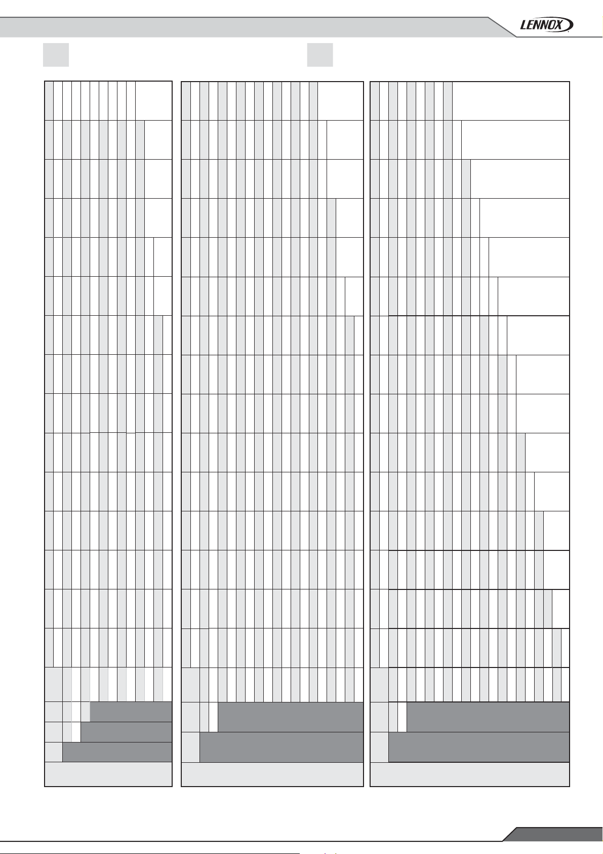
6- FAN PERFORMANCES
FAC FAH
Cooling only Heat pump
FAG
Cooling only with gas fi red heating Heat pump rooftop with gas fi red heating
FAM
Pa (kw)
KIT
Pa (kw)
KIT
Pa (kw)
KIT
Pa (kw)
KIT
Pa (kw)
KIT
Pa (kw)
KIT
Pa (kw)
KIT
Pa (kw)
KIT
No kit
No kit No kit No kit
No kit No kit
No kit
No kit
Pa (kw)
KIT
Pa (kw)
KIT
Pa (kw)
KIT
Pa (kw)
KIT
Pa (kw)
KIT
Pa (kw)
KIT
Pa (kw)
KIT
Pa (kw)
KIT
No kit
No kit No kit
No kit No kit
No kit
No kitNo kit
Pa (kw)
KIT
Pa (kw)
KIT
Pa (kw)
KIT
Pa (kw)
KIT
Pa (kw)
KIT
Pa (kw)
KIT
Pa (kw)
KIT
Pa (kw)
KIT
No kit
No kit
No kit
No kit
No kit
No kit
No kit
No kitNo kit
100 150 200 250 300 350 400 450 500 550 600 650 700 750 800
Pa (kw)
KIT
Pa (kw)
KIT
Pa (kw)
KIT
Pa (kw)
KIT
Pa (kw)
KIT
Pa (kw)
KIT
Pa (kw)
KIT
Airfl ow
12000 LP 1,56 LP 1,78 LP 2,02 LP 2,27 LP 2,53 LP 2,81 LP 3,09 LP 3,39 LP 3,70 LP 4,03 LP 4,36 LP 4,66 LP 4,98 LP 5,30 LP 5,63
13000 LP 1,86 LP 2,10 LP 2,35 LP 2,61 LP 2,89 LP 3,17 LP 3,46 LP 3,77 LP 4,09 LP 4,43 LP 4,77 LP 5,13 LP 5,50 LP 5,83 HP 6,19
14000 LP 2,21 LP 2,46 LP 2,72 LP 3,00 LP 3,28 LP 3,59 LP 3,89 LP 4,21 LP 4,54 LP 4,88 LP 5,24 LP 5,60 HP 6,04 HP 6,40 HP 6,76
15000 LP 2,60 LP 2,87 LP 3,15 LP 3,44 LP 3,74 LP 4,05 LP 4,37 LP 4,71 LP 5,05 LP 5,40 LP 5,76 HP 6,24 HP 6,60 HP 6,97 HP 7,35
16000 LP 3,04 LP 3,34 LP 3,63 LP 3,93 LP 4,25 LP 4,57 LP 4,91 LP 5,26 LP 5,62 HP 6,15 HP 6,50 HP 6,86 HP 7,23 HP 7,61 HP 8,00
17000 LP 3,54 LP 3,86 LP 4,17 LP 4,49 LP 4,82 LP 5,16 LP 5,51 HP 6,04 HP 6,42 HP 6,80 HP 7,17 HP 7,54 HP 7,93 HP 8,31 HP 8,71
18000 LP 4,10 LP 4,45 LP 4,78 LP 5,12 LP 5,46 HP 5,96 HP 6,33 HP 6,71 HP 7,09 HP 7,49 HP 7,90 HP 8,30 HP 8,69 HP 9,10 HP 9,51
19000 LP 4,73 LP 5,10 HP 5,59 HP 5,94 HP 6,30 HP 6,67 HP 7,05 HP 7,44 HP 7,84 HP 8,25 HP 8,67 HP 9,10 HP 9,54 HP 9,96 HP 10,38
20000 HP 5,56 HP 5,93 HP 6,31 HP 6,69 HP 7,06 HP 7,45 HP 7,84 HP 8,25 HP 8,66 HP 9,09 HP 9,52 HP 9,96 HP 10,42 HP 10,88
21000 HP 6,32 HP 6,70 HP 7,10 HP 7,51 HP 7,91 HP 8,30 HP 8,71 HP 9,13 HP 9,56 HP 10,00 HP 10,45
22000 HP 7,17 HP 7,56 HP 7,97 HP 8,40 HP 8,83 HP 9,24 HP 9,67 HP 10,10 HP 10,55
23000 HP 8,09 HP 8,50 HP 8,93 HP 9,37 HP 9,83 HP 10,27 no kit 0,00
100 150 200 250 300 350 400 450 500 550 600 650 700 750 800
Pa (kw)
KIT
Pa (kw)
KIT
Pa (kw)
KIT
Pa (kw)
KIT
Pa (kw)
KIT
Pa (kw)
KIT
Pa (kw)
KIT
Airfl ow
18000 LP 2,19 LP 2,52 LP 2,87 LP 3,23 LP 3,62 LP 4,02 LP 4,44 LP 4,87 LP 5,33 LP 5,82 LP 6,32 LP 6,78 LP 7,25 LP 7,72 LP 8,21
19000 LP 2,46 LP 2,80 LP 3,16 LP 3,54 LP 3,94 LP 4,35 LP 4,77 LP 5,22 LP 5,69 LP 6,17 LP 6,68 LP 7,21 LP 7,73 LP 8,22 HP 8,76
20000 LP 2,75 LP 3,11 LP 3,48 LP 3,87 LP 4,28 LP 4,71 LP 5,15 LP 5,60 LP 6,07 LP 6,57 LP 7,08 LP 7,61 LP 8,17 LP 8,74 HP 9,27
21000 LP 3,06 LP 3,45 LP 3,84 LP 4,24 LP 4,65 LP 5,09 LP 5,55 LP 6,01 LP 6,49 LP 7,00 LP 7,52 LP 8,06 LP 8,62 HP 9,27 HP 9,81
22000 LP 3,41 LP 3,82 LP 4,22 LP 4,63 LP 5,06 LP 5,51 LP 5,98 LP 6,46 LP 6,96 LP 7,46 LP 7,99 LP 8,54 HP 9,24 HP 9,78 HP 10,34
23000 LP 3,78 LP 4,22 LP 4,63 LP 5,06 LP 5,51 LP 5,97 LP 6,45 LP 6,94 LP 7,45 LP 7,97 LP 8,51 HP 9,26 HP 9,80 HP 10,34 HP 10,91
24000 LP 4,19 LP 4,65 LP 5,08 LP 5,53 LP 5,98 LP 6,46 LP 6,95 LP 7,46 LP 7,99 LP 8,52 HP 9,32 HP 9,85 HP 10,39 HP 10,95 HP 11,52
25000 LP 4,63 LP 5,10 LP 5,57 LP 6,03 LP 6,50 LP 6,99 LP 7,49 LP 8,01 LP 8,55 HP 9,37 HP 9,93 HP 10,47 HP 11,02 HP 11,59 HP 12,17
26000 LP 5,11 LP 5,60 LP 6,10 LP 6,57 LP 7,06 LP 7,56 LP 8,08 HP 8,86 HP 9,41 HP 9,98 HP 10,56 HP 11,14 HP 11,71 HP 12,28 HP 12,87
27000 LP 5,63 LP 6,13 LP 6,66 LP 7,15 LP 7,65 LP 8,17 HP 8,93 HP 9,48 HP 10,04 HP 10,62 HP 11,22 HP 11,83 HP 12,43 HP 13,02 HP 13,62
28000 LP 6,18 LP 6,71 LP 7,25 LP 7,78 HP 8,50 HP 9,03 HP 9,58 HP 10,14 HP 10,71 HP 11,31 HP 11,91 HP 12,54 HP 13,17 HP 13,81 HP 14,42
29000 LP 6,78 LP 7,32 LP 7,88 HP 8,62 HP 9,17 HP 9,71 HP 10,27 HP 10,84 HP 11,43 HP 12,04 HP 12,66 HP 13,29 HP 13,94 HP 14,61 HP 15,27
30000 LP 7,43 HP 8,19 HP 8,73 HP 9,30 HP 9,88 HP 10,44 HP 11,01 HP 11,60 HP 12,20 HP 12,82 HP 13,45 HP 14,10 HP 14,76 HP 15,44 HP 16,13
31000 HP 8,36 HP 8,89 HP 9,45 HP 10,02 HP 10,62 HP 11,21 HP 11,80 HP 12,40 HP 13,01 HP 13,64 HP 14,29 HP 14,95 HP 15,63 HP 16,32
32000 HP 9,09 HP 9,64 HP 10,21 HP 10,80 HP 11,41 HP 12,04 HP 12,64 HP 13,25 HP 13,88 HP 14,52 HP 15,18 HP 15,86
33000 HP 9,87 HP 10,43 HP 11,02 HP 11,62 HP 12,25 HP 12,90 HP 13,53 HP 14,15 HP 14,79 HP 15,45
34000 HP 10,70 HP 11,28 HP 11,88 HP 12,49 HP 13,14 HP 13,80 HP 14,47 HP 15,11 HP 15,77
35000 HP 11,58 HP 12,18 HP 12,79 HP 13,42 HP 14,08 HP 14,76 HP 15,45
100 150 200 250 300 350 400 450 500 550 600 650 700 750 800
Pa (kw)
KIT
Pa (kw)
KIT
Pa (kw)
KIT
Pa (kw)
KIT
Pa (kw)
KIT
Pa (kw)
KIT
Pa (kw)
KIT
Airfl ow
24000 LP 2,98 LP 3,40 LP 3,87 LP 4,37 LP 4,87 LP 5,37 LP 5,89 LP 6,43 LP 6,99 LP 7,58 LP 8,18 LP 8,77 HP 9,34 HP 9,92 HP 10,51
25000 LP 3,25 LP 3,70 LP 4,17 LP 4,68 LP 5,22 LP 5,73 LP 6,26 LP 6,82 LP 7,39 LP 7,98 LP 8,60 HP 9,26 HP 9,83 HP 10,41 HP 11,01
26000 LP 3,55 LP 4,03 LP 4,50 LP 5,02 LP 5,57 LP 6,12 LP 6,66 LP 7,23 LP 7,81 LP 8,41 HP 9,07 HP 9,73 HP 10,35 HP 10,94 HP 11,55
27000 LP 3,87 LP 4,38 LP 4,85 LP 5,38 LP 5,94 LP 6,53 LP 7,09 LP 7,66 LP 8,26 LP 8,87 HP 9,51 HP 10,17 HP 10,85 HP 11,51 HP 12,12
28000 LP 4,21 LP 4,75 LP 5,23 LP 5,76 LP 6,34 LP 6,94 LP 7,54 LP 8,13 LP 8,74 HP 9,34 HP 9,98 HP 10,64 HP 11,33 HP 12,04 HP 12,73
29000 LP 4,58 LP 5,13 LP 5,65 LP 6,18 LP 6,76 LP 7,38 LP 8,01 LP 8,62 HP 9,21 HP 9,84 HP 10,48 HP 11,15 HP 11,84 HP 12,56 HP 13,30
30000 LP 4,98 LP 5,54 LP 6,09 LP 6,62 LP 7,21 LP 7,84 LP 8,49 HP 9,12 HP 9,73 HP 10,36 HP 11,02 HP 11,69 HP 12,39 HP 13,11 HP 13,86
31000 LP 5,40 LP 5,97 LP 6,56 LP 7,10 LP 7,70 LP 8,34 HP 8,98 HP 9,63 HP 10,28 HP 10,92 HP 11,59 HP 12,27 HP 12,97 HP 13,70
32000 LP 5,86 LP 6,43 LP 7,07 LP 7,61 LP 8,21 HP 8,87 HP 9,51 HP 10,17 HP 10,86 HP 11,51 HP 12,19 HP 12,88 HP 13,59
33000 LP 6,34 LP 6,93 LP 7,57 LP 8,16 HP 8,81 HP 9,42 HP 10,07 HP 10,74 HP 11,43 HP 12,14 HP 12,82 HP 13,52
34000 LP 6,86 LP 7,45 LP 8,11 HP 8,78 HP 9,38 HP 10,01 HP 10,66 HP 11,34 HP 12,05 HP 12,78 HP 13,49
35000 LP 7,40 HP 8,10 HP 8,74 HP 9,38 HP 9,99 HP 10,62 HP 11,29 HP 11,98 HP 12,69 HP 13,43
36000 HP 8,06 HP 8,67 HP 9,33 HP 10,01 HP 10,63 HP 11,28 HP 11,95 HP 12,65 HP 13,38
37000 HP 8,65 HP 9,29 HP 9,96 HP 10,67 HP 11,31 HP 11,96 HP 12,65 HP 13,36
38000 HP 9,29 HP 9,93 HP 10,62 HP 11,34 HP 12,02 HP 12,69
39000 HP 9,96 HP 10,62 HP 11,32 HP 12,05 HP 12,77
No kit
40000 HP 10,66 HP 11,34 HP 12,05 HP 12,80
41000 HP 11,40 HP 12,10
No kit
No kit
No kit
No kit
42000 HP 12,18
No kit
43000
F085 F100 F120
LP HP
Low Pressure High Pressure
FAG/FAM 80-120
F150 F170
150-170
Application Guide /FLEXAIR-AGU-1505-E
F200 F230
FAG/FAM
200-230
FAG/FAM
• 43 •
Page 46
6.- FAN PERFORMANCES
6.2- EXHAUST FAN PERFORMANCES
FAC FAH
Cooling only Heat pump
FAG FAM
Cooling only with gas fi red heating Heat pump rooftop with gas fi red heating
Pa (kw)
KIT
Pa (kw)
KIT
Pa (kw)
KIT
Pa (kw)
KIT
Pa (kw)
KIT
Pa (kw)
Pa (kw)
KIT
Pa (kw)
KIT
Pa (kw)
KIT
Pa (kw)
KIT
Pa (kw)
KIT
Pa (kw)
Pa (kw)
No kit
KIT
Pa (kw)
No kit
KIT
Pa (kw)
No kit
KIT
Pa (kw)
No kit
KIT
Pa (kw)
No kit
KIT
Pa (kw)
150 200 250 300 350 400 450 500 550 600
Airfl ow
KIT
Pa (kw)
KIT
Pa (kw)
KIT
Pa (kw)
KIT
Pa (kw)
KIT
12000 LP 1,02 LP 1,26 LP 1,51 LP 1,76 LP 2,04 LP 2,33 LP 2,61 LP 2,91 LP 3,23 LP 3,56
13000 LP 1,13 LP 1,37 LP 1,64 LP 1,91 LP 2,19 LP 2,48 LP 2,79 LP 3,10 LP 3,42 LP 3,75
14000 LP 1,25 LP 1,51 LP 1,78 LP 2,07 LP 2,36 LP 2,66 LP 2,97 LP 3,30 LP 3,64 LP 3,97
15000 LP 1,39 LP 1,67 LP 1,93 LP 2,23 LP 2,55 LP 2,86 LP 3,17 LP 3,51 LP 3,85 LP 4,22
16000 LP 1,55 LP 1,82 LP 2,12 LP 2,41 LP 2,73 LP 3,07 LP 3,40 LP 3,74 LP 4,09 LP 4,46
17000 LP 1,72 LP 2,00 LP 2,31 LP 2,62 LP 2,93 LP 3,28 LP 3,64 LP 4,00 LP 4,36 LP 4,73
18000 LP 1,91 LP 2,21 LP 2,51 LP 2,86 LP 3,16 LP 3,51 LP 3,88 LP 4,27 LP 4,64 LP 5,03
19000 LP 2,14 LP 2,43 LP 2,74 LP 3,08 LP 3,44 LP 3,77 LP 4,14 LP 4,53 LP 4,94 LP 5,35
20000 LP 2,38 LP 2,67 LP 3,00 LP 3,33 LP 3,70 LP 4,07 LP 4,43 LP 4,82 LP 5,24 LP 5,68
21000 LP 2,65 LP 2,94 LP 3,27 LP 3,62 LP 3,99 LP 4,39 LP 4,76 LP 5,15 LP 5,57 HP 6,00
22000 LP 2,94 LP 3,24 LP 3,57 LP 3,94 LP 4,30 LP 4,70 LP 5,14 LP 5,52 HP 5,95 HP 6,37
23000 LP 3,26 LP 3,58 LP 3,89 LP 4,27 LP 4,66 LP 5,05 HP 5,53 HP 5,95 HP 6,35 HP 6,77
150 200 250 300 350 400 450 500 550 600
KIT
Pa (kw)
KIT
Pa (kw)
KIT
Pa (kw)
KIT
Pa (kw)
KIT
Airfl ow
18000 LP 1,61 LP 1,98 LP 2,36 LP 2,75 LP 3,16 LP 3,60 LP 4,03 LP 4,48 LP 4,97 LP 5,47
19000 LP 1,74 LP 2,11 LP 2,51 LP 2,91 LP 3,33 LP 3,77 LP 4,23 LP 4,68 LP 5,17 LP 5,67
20000 LP 1,88 LP 2,25 LP 2,66 LP 3,08 LP 3,50 LP 3,95 LP 4,42 LP 4,90 LP 5,39 LP 5,90
21000 LP 2,02 LP 2,40 LP 2,82 LP 3,26 LP 3,69 LP 4,15 LP 4,62 LP 5,13 LP 5,63 LP 6,14
22000 LP 2,16 LP 2,57 LP 2,98 LP 3,44 LP 3,90 LP 4,36 LP 4,84 LP 5,35 LP 5,88 LP 6,41
23000 LP 2,33 LP 2,76 LP 3,17 LP 3,63 LP 4,12 LP 4,59 LP 5,08 LP 5,59 LP 6,12 LP 6,68
24000 LP 2,51 LP 2,94 LP 3,37 LP 3,83 LP 4,33 LP 4,83 LP 5,33 LP 5,85 LP 6,39 LP 6,95
25000 LP 2,70 LP 3,13 LP 3,60 LP 4,04 LP 4,55 LP 5,08 LP 5,60 LP 6,13 LP 6,67 LP 7,24
26000 LP 2,90 LP 3,34 LP 3,84 LP 4,28 LP 4,78 LP 5,32 LP 5,88 LP 6,42 LP 6,98 LP 7,55
27000 LP 3,12 LP 3,57 LP 4,06 LP 4,55 LP 5,04 LP 5,58 LP 6,15 LP 6,73 LP 7,30 LP 7,88
28000 LP 3,35 LP 3,82 LP 4,30 LP 4,84 LP 5,32 LP 5,86 LP 6,44 LP 7,04 LP 7,64 LP 8,23
29000 LP 3,60 LP 4,08 LP 4,57 LP 5,11 LP 5,63 LP 6,16 LP 6,74 LP 7,35 LP 7,99 LP 8,60
30000 LP 3,86 LP 4,36 LP 4,85 LP 5,39 LP 5,96 LP 6,49 LP 7,06 LP 7,68 LP 8,33 HP 8,97
31000 LP 4,16 LP 4,65 LP 5,16 LP 5,70 LP 6,30 LP 6,84 LP 7,41 LP 8,03 HP 8,69 HP 9,32
32000 LP 4,47 LP 4,96 LP 5,49 LP 6,03 LP 6,62 LP 7,23 LP 7,79 LP 8,40 HP 9,07 HP 9,71
33000 LP 4,81 LP 5,28 LP 5,83 LP 6,38 LP 6,97 LP 7,62 LP 8,20 HP 8,85 HP 9,47 HP 10,12
34000 LP 5,16 LP 5,63 LP 6,19 LP 6,76 LP 7,35 LP 7,99 HP 8,68 HP 9,28 HP 9,90 HP 10,55
35000 LP 5,53 LP 6,01 LP 6,58 LP 7,16 LP 7,75 HP 8,47 HP 9,13 HP 9,73 HP 10,35 HP 11,01
150 200 250 300 350 400 450 500 550 600
KIT
Pa (kw)
KIT
Pa (kw)
KIT
Pa (kw)
KIT
Pa (kw)
KIT
Airfl ow
24000 LP 2,50 LP 2,93 LP 3,37 LP 3,82 LP 4,32 LP 4,83 LP 5,33 LP 5,84 LP 6,38 LP 6,94
25000 LP 2,70 LP 3,13 LP 3,59 LP 4,04 LP 4,54 LP 5,07 LP 5,59 LP 6,12 LP 6,67 LP 7,23
26000 LP 2,90 LP 3,33 LP 3,83 LP 4,28 LP 4,78 LP 5,32 LP 5,88 LP 6,41 LP 6,97 LP 7,54
27000 LP 3,12 LP 3,56 LP 4,05 LP 4,54 LP 5,03 LP 5,57 LP 6,15 LP 6,72 LP 7,29 LP 7,87
28000 LP 3,35 LP 3,81 LP 4,29 LP 4,83 LP 5,31 LP 5,85 LP 6,43 LP 7,03 LP 7,63 LP 8,22
29000 LP 3,59 LP 4,07 LP 4,56 LP 5,10 LP 5,62 LP 6,15 LP 6,73 LP 7,34 LP 7,98 LP 8,59
30000 LP 3,86 LP 4,35 LP 4,84 LP 5,38 LP 5,95 LP 6,48 LP 7,05 LP 7,67 LP 8,32 HP 8,95
31000 LP 4,15 LP 4,64 LP 5,15 LP 5,69 LP 6,29 LP 6,83 LP 7,40 LP 8,02 HP 8,67 HP 9,31
32000 LP 4,47 LP 4,95 LP 5,48 LP 6,02 LP 6,61 LP 7,22 LP 7,78 LP 8,39 HP 9,05 HP 9,70
33000 LP 4,80 LP 5,27 LP 5,82 LP 6,37 LP 6,96 LP 7,61 LP 8,19 HP 8,84 HP 9,46 HP 10,10
34000 LP 5,15 LP 5,62 LP 6,18 LP 6,75 LP 7,33 LP 7,98 HP 8,67 HP 9,26 HP 9,88 HP 10,53
35000 LP 5,52 LP 6,00 LP 6,56 LP 7,15 LP 7,74 HP 8,45 HP 9,12 HP 9,71 HP 10,34 HP 10,99
36000 LP 5,91 LP 6,40 LP 6,96 LP 7,56 HP 8,24 HP 8,87 HP 9,54 HP 10,19 HP 10,82 HP 11,47
37000 LP 6,32 LP 6,83 LP 7,38 HP 8,06 HP 8,68 HP 9,31 HP 9,98 HP 10,69 HP 11,33 HP 11,99
38000 LP 6,76 HP 7,34 HP 7,88 HP 8,51 HP 9,14 HP 9,78 HP 10,45 HP 11,17 HP 11,87 HP 12,53
39000 HP 7,24 HP 7,79 HP 8,35 HP 8,97 HP 9,62 HP 10,27 HP 10,95 HP 11,67 HP 12,42
40000 HP 7,70 HP 8,27 HP 8,85 HP 9,46 HP 10,12 HP 10,79 HP 11,48 HP 12,19
41000 HP 8,19 HP 8,78 HP 9,36 HP 9,97 HP 10,65 HP 11,34 HP 12,03
42000 HP 8,71 HP 9,30 HP 9,91 HP 10,52 HP 11,20 HP 11,90
43000 HP 9,24 HP 9,85 HP 10,47 HP 11,10 HP 11,78
F085 F100 F120
85-120
F150 F170
150-170
FAC/FAH/FAG/FAM
FAC/FAH/FAG/FAM
LP HPLow Pressure High Pressure
• 44 •
F200 F230
200-230
FAC/FAH/FAG/FAM
Application Guide / FLEXAIR-AGU-1505-E
Page 47
7- HEAT RECOVERY SOLUTIONS PERFORMANCES
7.1- ROTARY WHEEL HEAT RECOVERY SYSTEM
ENERGY RECOVERY MODULE
Heating and cooling mode
%
Fresh air
Nominal airfl ow rate (m3/h)
COOLING MODE
085 100 120 150 170 200 230
15000 18500 20500 26000 30000 35000 39000
Conditions : 27°C / 47% HR
35°C / 50 % HR
Size
20%
60%
90%
100%
Heat recovery cooling capacity kW
Heat recovery cooling absorbed power kW
Effi ciency %
Heat recovery cooling capacity kW
Heat recovery cooling absorbed power kW
Effi ciency %
Heat recovery cooling capacity kW
Heat recovery cooling absorbed power kW
Effi ciency %
Heat recovery cooling capacity kW
Heat recovery cooling absorbed power kW
Effi ciency %
%
Fresh air
Nominal airfl ow rate (m
HEATING MODE
14,2 17,1 18,8 24,2 27,4 32,4 35,7
0,18 0,18 0,18 0,18 0,18 0,18 0,18
84 82 81 83 81 82 81
35,7 41,6 44,6 59,0 65,1 78,6 84,6
0,18 0,18 0,18 0,18 0,18 0,18 0,18
71 67 64 67 64 67 64
47,5 54,0 57,2 76,8 83,3 101,9 108,3
0,18 0,18 0,18 0,18 0,18 0,18 0,18
62 58 55 58 55 58 55
50,7 57,3 60,4 81,6 88,0 108,1 114,4
0,18 0,18 0,18 0,18 0,18 0,18 0,18
60 55 52 56 52 55 52
Conditions :
20°C / 70% HR / -7°C
Size
085 100 120 150 170 200 230
3
/h)
15000 18500 20500 26000 30000 35000 39000
20%
60%
90%
100%
Heat recovery cooling capacity kW
Heat recovery cooling absorbed power kW
Effi ciency %
Heat recovery cooling capacity kW
Heat recovery cooling absorbed power kW
Effi ciency %
Heat recovery cooling capacity kW
Heat recovery cooling absorbed power kW
Effi ciency %
Heat recovery cooling capacity kW
Heat recovery cooling absorbed power kW
Effi ciency %
16,5 19,9 21,7 28,1 31,8 37,6 41,3
0,18 0,18 0,18 0,18 0,18 0,18 0,18
87 85 84 85 84 85 84
40,8 47,2 50,5
0,18 0,18 0,18 0,18 0,18 0,18 0,18
72 67 65 68 65 67 65
53,5 60,4 63,8 86,1 92,9 114,1 120,8
0,18 0,18 0,18 0,18 0,18 0,18 0,18
63 57 55 58 54 57 54
57,0 63,9 67,1 91,1 97,7 120,6 127,0
0,18 0,18 0,18 0,18 0,18 0,18 0,18
60 55 52 55 51 54 51
67,0 73,6 89,2 95,7
Application Guide /FLEXAIR-AGU-1505-E
• 45 •
Page 48

7- HEAT RECOVERY SOLUTIONS PERFORMANCES
ENERGY RECOVERY MODULE
Heating and cooling modes
Conditions :
20°C / 70% HR / 7°C
20%
60%
90%
100%
%
Fresh air
Nominal airfl ow rate (m3/h)
Heat recovery cooling capacity kW
Heat recovery cooling absorbed power kW
Effi ciency %
Heat recovery cooling capacity kW
Heat recovery cooling absorbed power kW
Effi ciency %
Heat recovery cooling capacity kW
Heat recovery cooling absorbed power kW
Effi ciency %
Heat recovery cooling capacity kW
Heat recovery cooling absorbed power kW
Effi ciency %
HEATING MODE
Size
085 100 120 150 170 200 230
15000 18500 20500 26000 30000 35000 39000
32,9 39,6 43,3 55,9 63,3 75,0 82,3
0,18 0,18 0,18 0,18 0,18 0,18 0,18
88 86 85 86 85 86 85
80,7 93,1 99,5 132,2 145,1 176,0 188,6
0,18 0,18 0,18 0,18 0,18 0,18 0,18
72 67 65 68 65 67 65
105,4 118,7 125,0 169,1 182,0 224,1 236,7
0,18 0,18 0,18 0,18 0,18 0,18 0,18
63 57 55 58 54 57 54
112,0 125,2 131,4 178,7 191,2 236,4 248,7
0,18 0,18 0,18 0,18 0,18 0,18 0,18
60 54 52 55 51 54 51
• 46 •
Application Guide / FLEXAIR-AGU-1505-E
Page 49
8- HEATING AUXILIARIES PERFORMANCES
8.1- HOT WATER COIL PERFORMANCES
FCM FHM
Cooling only Heat pump
Return air at 0°C
water temperature
90-70 80-60 70-50
kW
(2)
Pressure drop
kPa
Air temperature
Water fl ow rate
/h
3
m
Heating capacity
kW
SIZE
(1)
Type
S
H
S
H
85
S
H
S
H
S
H
100
S
H
S
H
S
H
120
S
H
S
H
S
H
150
S
H
S
H
S
H
170
S
H
S
H
S
H
200
S
H
S
H
S
H
230
S
H
(1) S H
(2)
Standard heat High heat
Pressure drop = Internal coil + 3-way valve
/h
3
Airfl ow rate
m
Heating capacity
12000 142 109 33 6 123 83 28 5 104 59 24 4
217 90 50 9 189 69 44 8 160 50 37 7
15000 160 137 30 7 138 104 26 6 116 74 22 5
249 118 46 11 216 90 40 9 183 65 34 8
23000 ----170156217143111176
318 191 38 14 275 145 33 12 232 103 28 10
14000 154 127 31 7 133 97 26 6 112 69 22 5
239 109 47 10 207 83 41 9 175 60 35 8
18500 178 168 27 8 154 127 23 7 129 91 19 6
282 151 42 12 244 114 37 11 206 83 31 9
23000 ----170156217143111176
318 191 38 14 275 145 33 12 232 103 28 10
15000 160 137 30 7 138 104 26 6 116 74 22 5
249 118 46 11 216 90 40 9 183 65 34 8
20500 187 185 25 8 161 140 22 7 136 100 18 6
298 169 40 13 258 128 35 11 218 92 29 9
23000 ----170156217143111176
318 191 38 14 275 145 33 12 232 103 28 10
18000 172 50 26 7 148 37 23 6 123 26 19 5
286 70 44 12 249 54 38 11 211 40 33 9
26000 206 72 22 9 177 53 19 8 147 37 16 6
356 107 38 15 309 82 33 13 262 60 28 11
35000 236 94 19 10 202 69 16 9 169 49 13 7
420 147 33 18 364 113 29 16 308 83 24 13
21000 186 59 25 8 159 43 21 7 133 30 18 6
314 84 41 14 273 65 36 12 231 48 31 10
30000 220 82 20 10 189 60 17 8 158 42 15 7
386 125 36 17 335 96 31 14 283 70 26 12
35000 236 94 19 10 202 69 16 9 169 49 13 7
420 147 33 18 364 113 29 16 308 83 24 13
24000 208 62 24 9 178 46 21 8 149 32 17 6
335 78 39 14 290 60 34 13 246 44 28 11
35000 251 91 20 11 215 67 17 9 180 47 14 8
414 118 33 18 359 91 28 15 304 66 24 13
43000 277 110 18 12 237 81 15 10 198 57 13 9
461 147 30 20 400 112 26 17 338 82 22 15
27000 221 70 23 10 189 52 19 8 158 36 16 7
358 89 37 15 311 68 32 13 263 50 27 11
39000 264 101 19 11 227 74 16 10 189 52 13 8
438 133 31 19 380 101 27 16 322 74 23 14
43000 277 110 18 12 237 81 15 10 198 57 13 9
461 147 30 20 400 112 26 17 338 82 22 15
Water without glycol
Reminder : 10 kPa=1mCe = 1mH2O
Application Guide /FLEXAIR-AGU-1505-E
(2)
Pressure drop
kPa
Air temperature
Water fl ow rate
/h
3
m
(2)
Heating capacity
kW
Pressure drop
kPa
Air temperature
Water fl ow rate
• 47 •
/h
3
m
Page 50

8- HEATING AUXILIARIES PERFORMANCES
FCM FHM
Cooling only Heat pump
Return air at 10°C
90-70 80-60 70-50
water temperature
SIZE
85
100
120
150
170
200
230
(2)
(1)
Type
S
H
S
H
S
H
S
H
S
H
S
H
S
H
S
H
S
H
S
H
S
H
S
H
S
H
S
H
S
H
S
H
S
H
S
H
S
H
S
H
S
H
/h
3
Airfl ow rate
m
Heating capacity
kW
Pressure drop
kPa
Air temperature
12000 121 80 29 5 102 57 25 4 83 39 20 4
185 66 44 8 157 48 38 7 129 33 31 6
15000 137 100 26 6 115 72 22 5 94 49 18 4
213 87 41 9 180 63 34 8 147 43 28 6
23000 168 151 21 7 142 108 18 6 115 73 14 5
271 140 34 12 229 101 29 10 187 68 23 8
14000 132 94 27 6 111 67 23 5 90 46 19 4
204 80 42 9 173 58 35 7 141 39 29 6
18500 152 123 24 7 128 88 20 6 104 60 16 4
240 110 37 10 203 80 32 9 166 54 26 7
23000 168 151 21 7 142 108 18 6 115 73 14 5
271 140 34 12 229 101 29 10 187 68 23 8
15000 137 100 26 6 115 72 22 5 94 49 18 4
213 87 41 9 180 63 34 8 147 43 28 6
20500 160 136 22 7 134 97 19 6 109 66 15 5
255 124 36 11 215 90 30 9 175 60 25 8
23000 168 151 21 7 142 108 18 6 115 73 14 5
271 140 34 12 229 101 29 10 187 68 23 8
18000 146 36 23 6 122 26 20 5 99 17 16 4
244 52 39 11 208 38 33 9 170 26 27 7
26000 175 52 19 8 147 37 16 6 118 24 13 5
304 79 34 13 258 58 28 11 211 40 23 9
35000 201 68 16 9 168 48 14 7 135 31 11 6
358 109 29 15 304 80 25 13 248 54 20 11
21000 158 42 22 7 132 30 18 6 106 20 15 5
268 62 37 12 228 46 31 10 187 31 26 8
30000 187 59 18 8 157 42 15 7 126 27 12 5
329 92 32 14 279 68 27 12 229 46 22 10
35000 201 68 16 9 168 48 14 7 135 31 11 6
358 109 29 15 304 80 25 13 248 54 20 11
24000 176 45 21 8 148 32 18 6 119 21 14 5
286 58 34 12 242 42 29 10 199 29 24 9
35000 213 65 18 9 178 46 15 8 143 30 12 6
353 87 29 15 300 64 25 13 245 43 20 11
43000 235 79 16 10 197 56 13 8 158 36 11 7
394 108 26 17 334 79 22 14 273 54 18 12
27000 187 51 20 8 157 36 17 7 126 23 13 5
306 66 33 13 259 48 28 11 213 33 23 9
39000 225 72 17 10 188 51 14 8 151 33 11 7
374 98 28 16 317 72 23 14 260 49 19 11
43000 235 79 16 10 197 56 13 8 158 36 11 7
394 108 26 17 334 79 22 14 273 54 18 12
Water fl ow rate
/h
3
m
Heating capacity
kW
(2)
Pressure drop
kPa
Air temperature
Water fl ow rate
/h
3
m
(2)
Heating capacity
kW
Pressure drop
kPa
Air temperature
Water fl ow rate
/h
3
m
(1) S H
(2)
Standard heat High heat
Pressure drop = Internal coil + 3-way valve
Water without glycol
Reminder : 10 kPa=1mCe = 1mH
O
2
• 48 •
Application Guide / FLEXAIR-AGU-1505-E
Page 51

8- HEATING AUXILIARIES PERFORMANCES
FCM FHM
Cooling only Heat pump
Return air at 20°C
water temperature
90-70 80-60 70-50
SIZE
85
100
120
150
170
200
230
(2)
(1)
Type
S
H
S
H
S
H
S
H
S
H
S
H
S
H
S
H
S
H
S
H
S
H
S
H
S
H
S
H
S
H
S
H
S
H
S
H
S
H
S
H
S
H
/h
3
Airfl ow rate
m
Heating capacity
kW
Pressure drop
kPa
Air temperature
12000 101 56 25 4 83 38 20 4 64 23 16 3
155 47 38 7 127 32 31 5 99 20 25 4
15000 114 70 23 5 93 48 18 4 72 29 14 3
177 61 35 8 145 41 29 6 113 26 22 5
23000 140 106 18 6 114 71 15 5 88 43 11 4
226 98 29 10 185 66 24 8 143 41 19 6
14000 110 65 23 5 90 44 19 4 69 27 15 3
170 56 36 7 139 38 30 6 109 24 23 5
18500 126 86 20 5 103 58 17 4 79 35 13 3
201 78 32 9 164 52 26 7 127 32 20 6
23000 140 106 18 6 114 71 15 5 88 43 11 4
226 98 29 10 185 66 24 8 143 41 19 6
15000 114 70 23 5 93 48 18 4 72 29 14 3
177 61 35 8 145 41 29 6 113 26 22 5
20500 133 95 19 6 108 64 16 5 83 39 12 4
212 87 31 9 174 59 25 7 135 36 20 6
23000 140 106 18 6 114 71 15 5 88 43 11 4
226 98 29 10 185 66 24 8 143 41 19 6
18000 121 25 20 5 98 17 16 4 75 10 12 3
204 37 34 9 168 25 28 7 132 16 22 6
26000 145 36 17 6 117 24 13 5 89 14 10 4
254 56 29 11 209 38 24 9 163 24 19 7
35000 167 47 14 7 135 31 11 6 102 18 9 4
300 77 25 13 246 53 21 11 191 33 16 8
21000 131 29 19 6 106 19 15 5 81 11 11 3
224 44 32 10 184 30 26 8 144 19 20 6
30000 156 41 15 7 126 27 12 5 95 16 9 4
275 65 27 12 226 45 22 10 176 28 17 8
35000 167 47 14 7 135 31 11 6 102 18 9 4
300 77 25 13 246 53 21 11 191 33 16 8
24000 146 31 18 6 118 20 15 5 90 12 11 4
239 41 30 10 196 28 24 8 154 18 19 7
35000 177 45 15 8 143 30 12 6 108 17 9 5
295 62 25 13 242 42 21 10 189 26 16 8
43000 195 55 14 8 157 36 11 7 119 21 8 5
330 76 23 14 270 52 19 12 210 32 15 9
27000 156 35 17 7 126 23 14 5 96 13 11 4
256 47 28 11 210 32 23 9 164 20 18 7
39000 186 50 14 8 150 33 11 6 114 19 9 5
313 69 24 14 257 47 20 11 200 29 15 9
43000 195 55 14 8 157 36 11 7 119 21 8 5
330 76 23 14 270 52 19 12 210 32 15 9
Water fl ow rate
/h
3
m
Heating capacity
kW
(2)
Pressure drop
kPa
Air temperature
Water fl ow rate
/h
3
m
(2)
Heating capacity
kW
Pressure drop
kPa
Air temperature
Water fl ow rate
/h
3
m
(1) S H
(2)
Standard heat High heat
Pressure drop = Internal coil + 3-way valve
Water without glycol
Reminder : 10 kPa=1mCe = 1mH
O
2
Application Guide /FLEXAIR-AGU-1505-E
• 49 •
Page 52
8- HEATING AUXILIARIES PERFORMANCES
8.2- ELECTRICAL HEATERS
SIZE
AIRFLOW
m3/h
15000085
18500100
20500120
26000150
30000170
35000200
39000230
TYPE
S
S
S
Available
Capacity
30
54M
72H
30
54M
72H
30
54M
72H
45S
72M
108H
45S
72M
108H
72S
108M
162H
72S
108M
162H
Type of
Modulation
2 stages
0-100%
0-100%
2 stages
0-100%
0-100%
2 stages
0-100%
0-100%
2 stages
0-100%
0-100%
2 stages
0-100%
0-100%
2 stages
0-100%
0-100%
2 stages
0-100%
0-100%
Stages
Stage 1:
Stage 2:
Stage 1:
Stage 2:
Stage 1:
Stage 2:
Stage 1:
Stage 2:
Stage 1:
Stage 2:
Stage 1:
Stage 2:
Stage 1:
Stage 2:
Temp. Rise
ºCKW
2,9
5,7
5,250%-->
10,3100%-->
6,950%-->
13,8100%-->
2,3
4,6
4,250%-->
8,4100%-->
5,650%-->
11,2100%-->
2,1
4,2
3,850%-->
7,6100%-->
5,050%-->
10,1100%-->
2,5
5,0
4,050%-->
7,9100%-->
6,050%-->
11,9100%-->
2,2
4,3
3,450%-->
6,9100%-->
5,250%-->
10,3100%-->
2,9
5,9
4,450%-->
8,8100%-->
6,650%-->
13,3100%-->
2,6
5,3
4,050%-->
7,9100%-->
6,050%-->
11,9100%-->
• 50 •
Application Guide / FLEXAIR-AGU-1505-E
Page 53

8- HEATING AUXILIARIES PERFORMANCES
8.3- GAS BURNER PERFORMANCES
SIZE
Airfl ow rate
m3/h
15000085
18500100
20500120
26000150
TYPE
S
Gas power
input
Gas power
input
Electrical
absorbed
power
KWKWKW
Number of
stages
20.1655.260
20.1655.260S
20.1655.260S
20.25110.4120S
Modulation
Option
40%-->100%20.25110.4120H
40%-->100%20.25110.4120H
40%-->100%20.25110.4120H
40%-->100%20.25165.6180H
20.25110.4120S
30000170
40%-->100%20.25165.6180H
20.25165.6180S
35000200
40%-->100%20.25220.8240H
20.25165.6180S
39000230
40%-->100%20.25220.8240H
Application Guide /FLEXAIR-AGU-1505-E
• 51 •
Page 54
9- ACOUSTIC DATA IN SPECTRUM
OUTDOOR NOISE LEVEL - STANDARD
FAC/FAH
FAG/FAM
85
100
120
150
170
200
230
FAC/FAH
FAG/FAM
85
100
120
150
170
200
230
Spectrum per octave band
Airfl ow rate
(m3/h)
15000 125 57,0 58,1 64,4 70,9 74,7 74,6 73,7 67,2 80,1 49,2
18500 125 60,2 67,1 72,2 82,4 82,5 86,8 79,8 87,4 91,8 60,8
20500 125 56,8 61,9 74,7 78,4 79,4 83,8 77,4 84,4 88,8 57,8
28000 150 52,0 57,7 68,3 76,1 77,8 82,0 79,9 82,0 87,2 56,2
30000 175 57,1 58,8 73,3 74,1 77,6 78,8 80,8 79,4 85,9 54,9
35000 175 59,5 63,0 69,9 75,0 79,2 80,9 76,2 73,0 84,9 53,9
39000 175 57,3 60,3 69,2 75,7 78,2 78,5 81,0 73,4 85,2 54,2
ESP
(Pa)
63 125 250 500 1000 2000 4000 8000
Sound power
dB(A) (1)
Sound pressure
at 10 meters
Spectrum per octave band
Airfl ow rate
3
(m
/h)
15000 500
18500 500
20500 500
28000 500
30000 500
35000 500
39000 500
ESP
(Pa)
63 125 250 500 1000 2000 4000 8000
57,0 58,3 65,8 71,1 75,0 74,3 74,7 62,6 80,3 49,3
60,2 65,2 72,7 82,5 82,5 87,1 80,4 87,6 92,0 61,0
56,7 61,6 67,7 78,1 79,0 83,6 78,4 84,4 88,6 57,6
52,0 56,6 72,4 75,9 78,3 81,8 80,4 82,8 87,6 56,6
60,1 65,4 70,2 82,2 82,1 86,7 79,5 87,4 91,6 60,6
59,5 61,5 70,4 75,3 79,6 80,7 76,0 73,1 85,0 54,0
57,3 60,3 74,4 76,5 79,4 79,5 82,2 78,7 86,9 55,9
Sound power
dB(A) (1)
Sound pressure
at 10 meters
dB(A) (2)
dB(A) (2)
FAC/FAH
FAG/FAM
85
100
120
150
170
200
230
FAC/FAH
FAG/FAM
85
100
120
150
170
200
230
OUTDOOR NOISE LEVEL - LOW NOISE
Spectrum per octave band
Airfl ow rate
3
(m
/h)
15000 250 53,9 56,6 64,0 69,8 70,1 71,2 73,2 67,3 78,0 47,0
18500 250 58,9 65,7 71,4 79,2 78,0 77,4 72,9 87,4 89,0 58,0
20500 250 55,9 59,7 74,5 76,1 75,0 74,1 72,3 83,4 85,6 54,6
28000 300 58,0 58,6 68,4 74,2 72,8 76,3 79,0 81,2 84,9 53,9
30000 350 54,1 57,5 73,2 73,5 74,7 76,3 80,5 79,4 85,0 54,0
35000 350 56,5 61,7 69,5 73,6 74,1 77,4 74,0 73,0 82,0 51,0
39000 350 56,5 59,1 68,7 74,7 74,5 76,0 80,9 73,3 84,0 53,0
ESP
(Pa)
63 125 250 500 1000 2000 4000 8000
Spectrum per octave band
Airfl ow rate
(m3/h)
15000 500 54,0 56,8 65,5 70,0 71,0 70,5 74,4 62,7 78,3 47,3
18500 500 58,9 62,6 72,0 79,4 78,0 79,1 75,2 87,6 89,3 58,3
20500 500 55,7 59,3 66,5 75,5 73,6 72,7 74,9 83,4 85,2 54,2
28000 500 58,0 57,8 72,4 73,8 74,1 75,3 79,6 82,1 85,5 54,5
30000 500 58,8 63,0 68,7 78,7 76,8 75,5 70,7 87,4 88,6 57,6
35000 500 56,5 59,6 70,2 73,9 75,3 77,1 73,6 73,1 82,2 51,2
39000 500 56,6 59,1 74,3 75,7 76,9 77,7 82,1 78,6 86,1 55,1
ESP
(Pa)
63 125 250 500 1000 2000 4000 8000
Sound power
dB(A) (1)
Sound power
dB(A) (1)
Sound pressure
Sound pressure
at 10 meters
dB(A) (2)
at 10 meters
dB(A) (2)
(1) Total outdoor power levels
(2) Global outdoor sound pressure levels 10 m
• 52 •
Application Guide / FLEXAIR-AGU-1505-E
Page 55

9- ACOUSTIC DATA IN SPECTRUM
INDOOR NOISE LEVEL - STANDARD & LOW NOISE
FAC/FAH
85
100
120
150
170
200
230
FAC/FAH
85
100
120
150
170
200
230
Spectrum per octave band
Airfl ow rate
(m3/h)
15000 125 41,3 55,2 69,0 77,8 81,0 80,8 80,5 73,1 86,5 85
18500 125 50,2 70,2 77,1 82,4 86,7 84,0 78,4 73,8 90,2 90
20500 125 50,3 58,9 79,6 80,6 85,9 81,7 78,3 72,1 89,2 89
28000 150 47,8 62,1 75,6 84,5 87,7 87,6 86,8 79,9 93,1 91
30000 175 50,1 59,6 77,1 85,8 90,8 87,7 88,8 85,1 95,2 94
35000 175 50,1 64,0 75,9 83,9 84,8 87,7 80,7 78,6 91,3 86
39000 175 47,4 59,7 74,7 83,2 86,2 85,7 87,1 78,1 92,0 88
ESP
(Pa)
63 125 250 500 1000 2000 4000 8000
Sound power
return
dB(A)
Spectrum per octave band
Airfl ow rate
(m3/h)
15000 500 44,9 57,8 71,8 78,8 82,1 80,6 82,3 70,0 87,4 87
18500 500 48,1 60,2 75,2 83,7 87,1 86,3 80,2 78,2 91,4 89
20500 500 41,8 54,2 68,7 76,1 79,3 78,0 79,7 67,9 84,7 90
28000 500 50,0 59,1 76,3 85,0 90,5 87,1 87,9 83,5 94,5 92
30000 500 44,3 62,0 71,4 78,4 81,7 79,8 74,3 69,8 85,6 95
35000 500 49,6 61,5 76,6 85,2 88,5 87,8 81,6 79,8 92,8 91
39000 500 50,1 58,9 76,2 84,6 90,3 86,8 87,4 82,2 94,1 92
63 125 250 500 1000 2000 4000 8000
Sound power
return
dB(A)
Sound power
supply
dB(A)
Sound power
supply
dB(A)
FAG/FAM
85
100
120
150
170
200
230
FAG/FAM
85
100
120
150
170
200
230
INDOOR NOISE LEVEL - STANDARD & LOW NOISE
Spectrum per octave band
Airfl ow rate
(m3/h)
15000 250 41,3 55,2 69,0 77,8 81,0 80,8 80,5 73,1 86,5 84
18500 250 50,2 70,2 77,1 82,4 86,7 84,0 78,4 73,8 90,2 87
20500 250 50,3 58,9 79,6 80,6 85,9 81,7 78,3 72,1 89,2 89
28000 300 47,8 62,1 75,6 84,5 87,7 87,6 86,8 79,9 93,1 88
30000 350 50,1 59,6 77,1 85,8 90,8 87,7 88,8 85,1 95,2 90
35000 350 50,1 64,0 75,9 83,9 84,8 87,7 80,7 78,6 91,3 88
39000 350 47,4 59,7 74,7 83,2 86,2 85,7 87,1 78,1 92,0 90
63 125 250 500 1000 2000 4000 8000
Spectrum per octave band
Airfl ow rate
(m3/h)
15000 500 44,9 57,8 71,8 78,8 82,1 80,6 82,3 70,0 87,4 90
18500 500 48,1 60,2 75,2 83,7 87,1 86,3 80,2 78,2 91,4 91
20500 500 41,8 54,2 68,7 76,1 79,3 78,0 79,7 67,9 84,7 93
28000 500 50,0 59,1 76,3 85,0 90,5 87,1 87,9 83,5 94,5 94
30000 500 44,3 62,0 71,4 78,4 81,7 79,8 74,3 69,8 85,6 95
35000 500 49,6 61,5 76,6 85,2 88,5 87,8 81,6 79,8 92,8 93
39000 500 50,1 58,9 76,2 84,6 90,3 86,8 87,4 82,2 94,1 94
63 125 250 500 1000 2000 4000 8000
Sound power
return
dB(A)
Sound power
return
dB(A)
Sound power
supply
dB(A)
Sound power
supply
dB(A)
Application Guide /FLEXAIR-AGU-1505-E
• 53 •
Page 56

10- ELECTRICAL DATA
10.1- ELECTRICAL TABLES
With (not cumulative):
Transformer
Compressor
Condensing fan
Condensing fan (EC fan)
Indoor supply kit
ELECTRICAL
Electric heater
Gas burner
POWER AXIAL FAN VERTICAL
EXTRACTION
Axial extraction fan
(Vertical or horizontal)
085 100 120
PA FLA SUA PA FLA SUA PA FLA SUA
kW A A kW A A kW A A
0,21 0,53 0,53 0,21 0,53 0,53 0,21 0,53 0,53
31,1 50,6 183,3 34,8 58,6 226,3 46,6 75,6 252,8
3,9 7,8 16,9 3,9 7,8 16,9 5,0 10,3 23,7
3,7 5,7 5,7 3,7 5,7 5,7 4,2 6,4 6,4
LP
5,7 8,6 8,6 5,7 8,6 8,6 5,7 8,6 8,6
HP
11,0 16,8 16,8 11,0 16,8 16,8 11,0 16,8 16,8
S 30,0 41,2 41,2 30,0 41,2 41,2 30,0 41,2 41,2
M 54,0 74,2 74,2 54,0 74,2 74,2 54,0 74,2 74,2
H 72,0 99,0 99,0 72,0 99,0 99,0 72,0 99,0 99,0
S
0,16 0,40 0,40 0,16 0,40 0,40 0,16 0,40 0,40
H
0,25 0,63 0,63 0,25 0,63 0,63 0,25 0,63 0,63
1,0 1,8 5,1 1,0 1,8 5,10 1,0 1,8 5,1
5,7 8,6 8,6 5,7 8,6 8,6 5,7 8,6 8,6
ENERGY RECOVERY
Rotary wheel motor
With (not cumulative):
Transformer
Compressor
Condensing fan
Condensing fan (EC fan)
Indoor supply kit
ELECTRICAL
Electric heater
Gas burner
POWER AXIAL FAN VERTICAL
EXTRACTION
Axial extraction fan
(Vertical or horizontal)
0,09 0,29 1,16 0,09 0,29 1,16 0,09 0,29 1,16
150 170 200 230
PA FLA SUA PA FLA SUA PA FLA SUA PA FLA SUA
kW A A kW A A kW A A kW A A
0,30 0,75 0,75 0,30 0,75 0,75 0,30 0,75 0,75 0,30 0,75 0,75
54,4 88,4 265,6 62,2 101,2 233,9 69,5 117,2 284,9 93,2 151,2 328,4
3,9 7,8 16,9 5,0 10,3 23,7 7,8 15,6 33,8 9,9 20,6 47,5
3,7 5,7 5,7 4,2 6,4 6,4 7,4 11,4 11,4 8,4 12,8 12,8
LP
8,49 12,9 12,9 8,49 12,9 12,9 9,0 13,8 13,8 9,0 13,8 13,8
HP
16,5 25,2 25,2 16,5 25,2 25,2 14,1 21,9 21,9 14,1 21,9 21,9
S
45,0 61,8 61,8 45,0 61,8 61,8 72,0 99,0 99,0 72,0 99,0 99,0
M
72,0 99,0 99,0 72,0 99,0 99,0 108,0 148,5 148,5 108,0 148,5 148,5
H
108,0 148,5 148,5 108,0 148,5 148,5 162,0 195,3 195,3 162,0 195,3 195,3
S
0,25 0,63 0,63 0,25 0,63 0,63 0,25 0,63 0,63 0,25 0,63 0,63
H
0,25 0,63 0,63 0,25 0,63 0,63 0,25 0,63 0,63 0,25 0,63 0,63
1,02 1,83 5,10 1,02 1,83 5,10 1,02 1,83 5,10 1,02 1,83 5,10
8,5 12,9 12,9 8,5 12,9 12,9 9,0 13,8 13,8 9,0 13,8 13,8
ENERGY RECOVERY
Rotary wheel motor
PA S
Absorbed power (kW) Standard heat
FLA M
Full load amps (A) Medium heat
SUA H
Start up amps (A) High heat
• 54 •
0,18 0,58 2,32 0,18 0,58 2,32 0,18 0,58 2,32 0,18 0,58 2,32
Application Guide / FLEXAIR-AGU-1505-E
Page 57

10. ELECTRICAL DATA
10.2- CONTROL TERMINAL CONNECTION
MULTI UNIT S
1243
MAINTENANCE DISPLAY
321 321
0123456
T-
T+
V+
GND
J14J15
Master/Slave
connection
pLan
24Vac
LOCAL DISPLAY
4770703R
24V
RX-
RX+
GND
24V.F
4
24V.E
3
GND
R2
WHITE
BROWN
Bus
-
GND
+-Vout +
21
J9
BMS card
J1 J2
G
G0
U1U3U2
J11
J10
NO8
NO7
NO6
C2
Out5
Out4
Out3
Out2
GND
Tx/Rx +
GND
+
J13
U4
GND
U5
Tx/Rx -
J14
J12
J3
GND
+Vdc
+5VR
J15
J27
U6
NC1C1NO1
NC9C9NO10
DI7H
GND
J17
C10
DI7
DI8
DI7C
U8
J16
NO9
J25
J4
U7
+Vdc
+5VR
C2
C2
J19
J18
NC10
DI8H
U9
U10
C11
J28
J5
GND
+Vdc
+5VR
C2
C2
J21
J20
NO12
NO11
NO13
C11
J26
Y5
Y4
J6
GND
Y3Y1Y2
Customer connections
CUSTOMER CONNECTIONS
C6
V-IN
J23
J22
-
J29
U11
GND
DI9
U12
DI1
GND
DI2
DI10
J7
DI3
DI4
C8
C7
+
GND
DI9C
GND
J24
J8
Bus
Application Guide /FLEXAIR-AGU-1505-E
• 55 •
Page 58

11- DIMENSIONS
111 M
GA AAGM A G
FAC/FAH/FAG/FAM
85/100/120
• 56 •
Application Guide / FLEXAIR-AGU-1505-E
Page 59

11- DIMENSIONS
GA AAGM A G
FAC/FAH/FAG/FAM
085/100/120
Application Guide /FLEXAIR-AGU-1505-E
• 57 •
Page 60
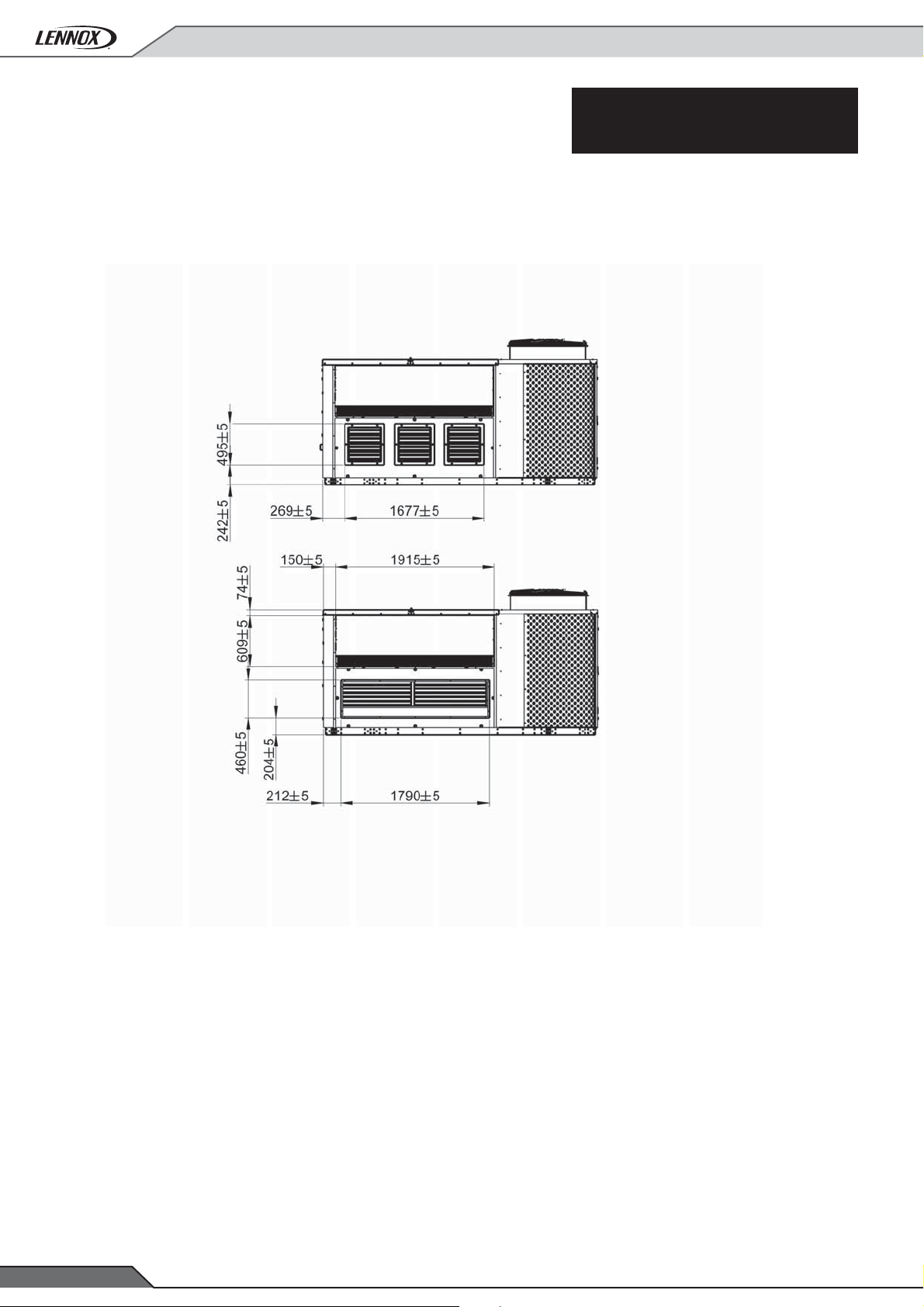
11- DIMENSIONS
GENERAL ARRANGEMENTS DRAWINGS
FAC/FAH/FAG/FAM
85/100/120
• 58 •
Application Guide / FLEXAIR-AGU-1505-E
Page 61
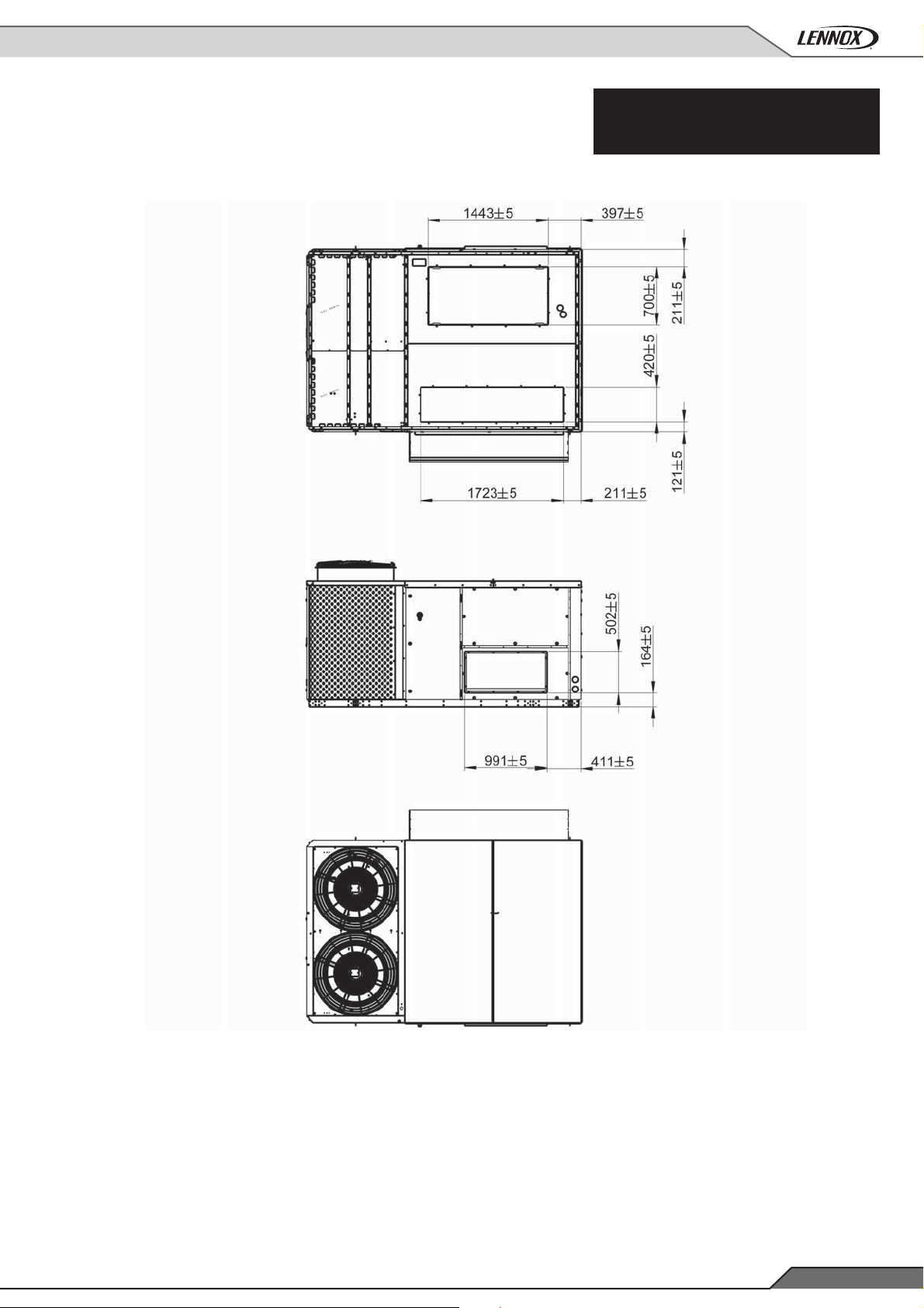
11- DIMENSIONS
GENERAL ARRANGEMENTS DRAWINGS
FAC/FAH/FAG/FAM
085/100/120
Application Guide /FLEXAIR-AGU-1505-E
• 59 •
Page 62

11- DIMENSIONS
GENERAL ARRANGEMENTS DRAWINGS
FAC/FAH/FAG/FAM
150/170
• 60 •
Application Guide / FLEXAIR-AGU-1505-E
Page 63

11- DIMENSIONS
GENERAL ARRANGEMENTS DRAWINGS
FAC/FAH/FAG/FAM
150/170
Application Guide /FLEXAIR-AGU-1505-E
• 61 •
Page 64

11- DIMENSIONS
GENERAL ARRANGEMENTS DRAWINGS
FAC/FAH/FAG/FAM
150/170
• 62 •
Application Guide / FLEXAIR-AGU-1505-E
Page 65

11- DIMENSIONS
GENERAL ARRANGEMENTS DRAWINGS
FAC/FAH/FAG/FAM
150/170
Application Guide /FLEXAIR-AGU-1505-E
• 63 •
Page 66

11- DIMENSIONS
GENERAL ARRANGEMENTS DRAWINGS
FAC/FAH/FAG/FAM
200/230
• 64 •
Application Guide / FLEXAIR-AGU-1505-E
Page 67

11- DIMENSIONS
GENERAL ARRANGEMENTS DRAWINGS
FAC/FAH/FAG/FAM
200/230
Application Guide /FLEXAIR-AGU-1505-E
• 65 •
Page 68

11- DIMENSIONS
GENERAL ARRANGEMENTS DRAWINGS
FAC/FAH/FAG/FAM
200/230
• 66 •
Application Guide / FLEXAIR-AGU-1505-E
Page 69

11- DIMENSIONS
GENERAL ARRANGEMENTS DRAWINGS
FAC/FAH/FAG/FAM
200/230
Application Guide /FLEXAIR-AGU-1505-E
• 67 •
Page 70
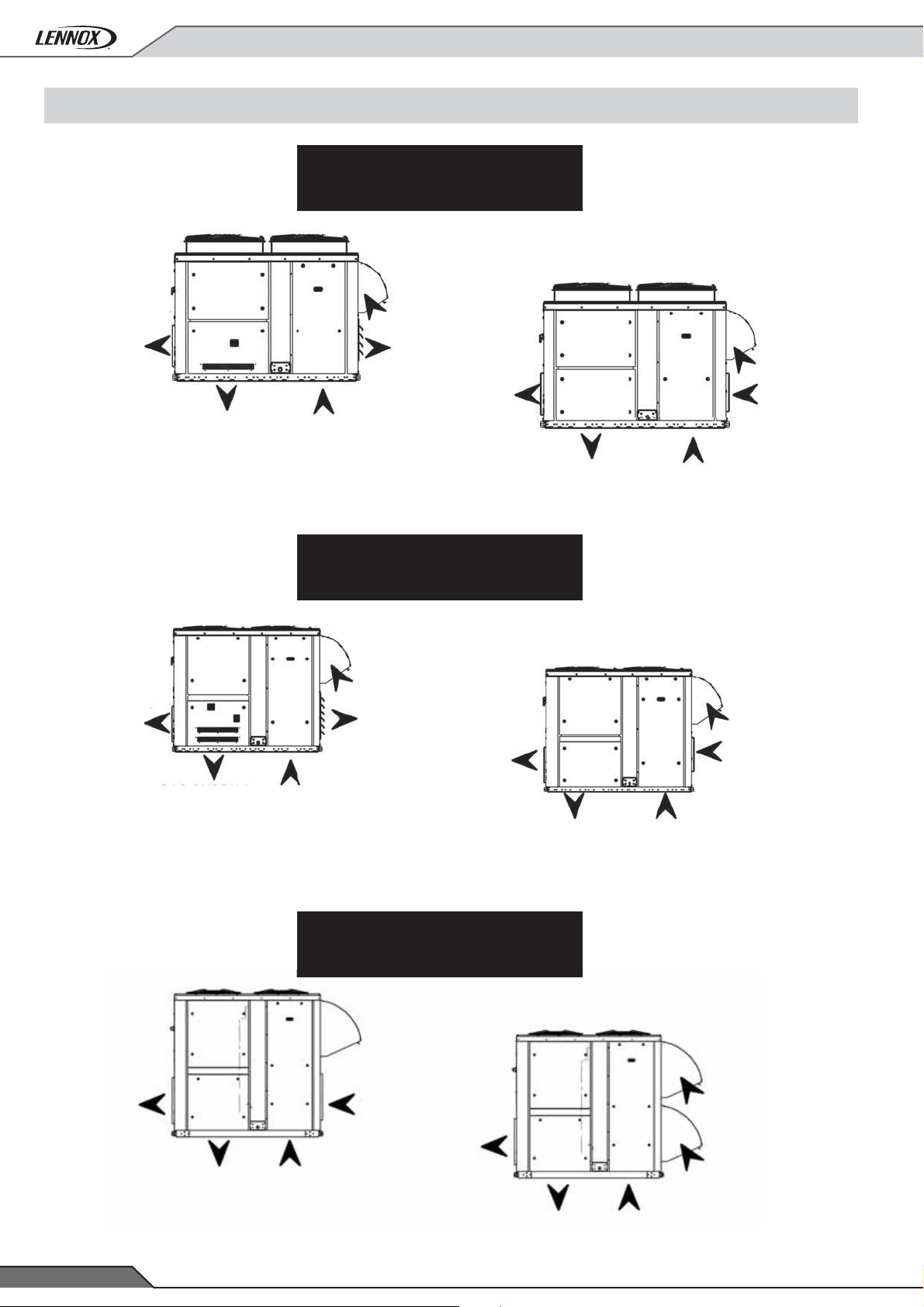
11- DIMENSIONS
11.2- AIRFLOW CONFIGURATION
FAC/FAH/FAG/FAM
85/100/120
Supply
(Option)
Supply
(Option)
Supply
(Standard)
Fresh air
Extraction
(option)
Supply
(Option)
Return
(Standard)
FAC/FAH/FAG/FAM
150/170
Fresh air
Extraction
(option)
Supply
(Standard)
Fresh air
Return
(option)
Return
(Standard)
Fresh air
Supply
(Option)
Supply
(Standard)
Supply
(Standard)
Supply
(Option)
Return
(Standard)
FAC/FAH/FAG/FAM
200/230
Supply
(Option)
Return
(Standard)
Supply
(Standard)
Return
(option)
Return
(Standard)
Fresh air
Fresh air
• 68 •
Supply
(Standard)
Return
(Standard)
Application Guide / FLEXAIR-AGU-1505-E
Page 71
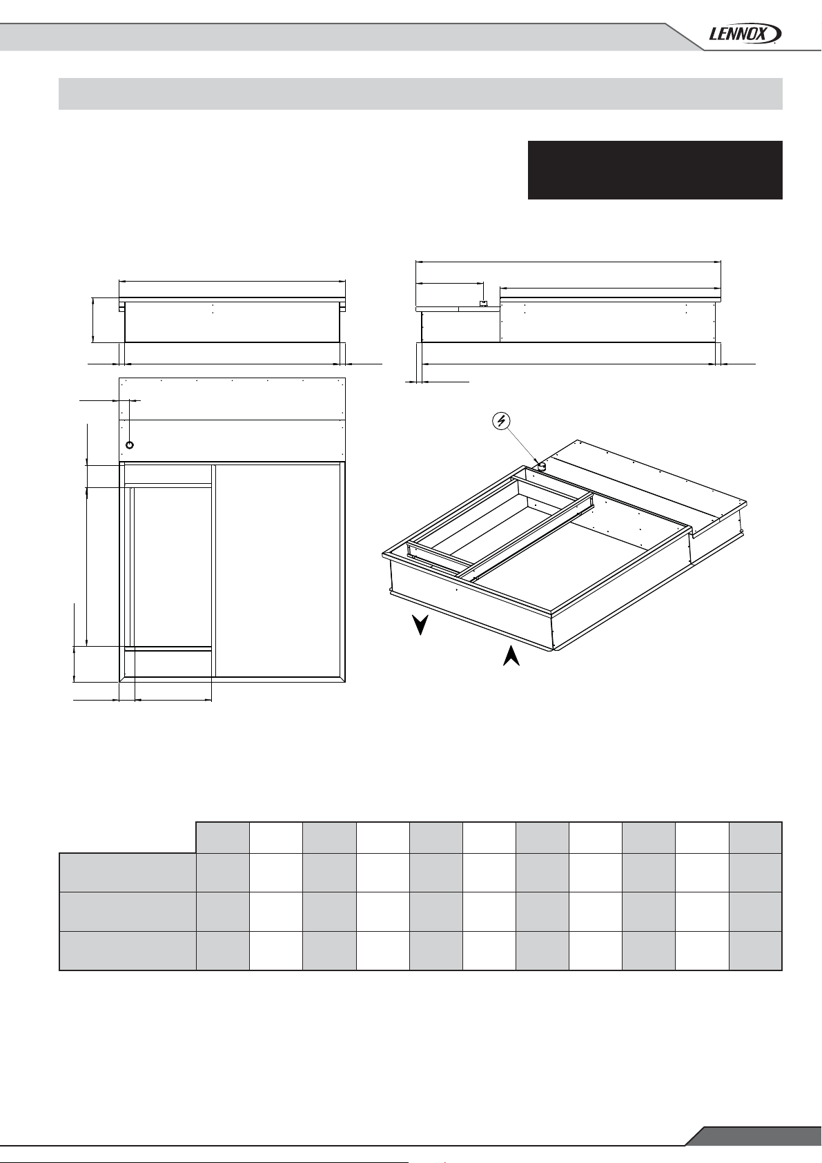
11- DIMENSIONS
11.3- ROOFCOURB DIMENSIONS
NON ADJUSTABLE ROOFCURB
2059 ± 15
E
1956 ± 1550 ± 5
F
GH
50 ± 5
B
50 ± 5
FAC/FAH/FAG/FAM
A
C
D
50 ± 5
J
KL
85-100-120
150-170
200-230
DIMENSIONS
ABCDEFGHJ KL
2771 614 2005 2669 410 96 207 1443 326 139 700
3466 800 2493 3365 410 95 491 1540 433 139 700
4066 1106 2493 3965 425 95 233 1830 432 89 800
Application Guide /FLEXAIR-AGU-1505-E
• 69 •
Page 72

11- DIMENSIONS
D
100 ± 5
95 ± 5
FGH
ADJUSTABLE ROOFCURB
2064 ± 15
14%
1958 ± 15
100 ± 5 100 ± 5 E
FAC/FAH/FAG/FAM
BC
A
Q
100 ± 5
JK L
422 ± 15
ABCDEFGHJ KLMNPQ
85-100-120
150-170
200-230
2771 614 2006 400 2672 237 1443 326 140 700 145 131 1747 128 10 %
3467 800 2494 400 3368 520 1540 433 140 700 146 235 1997 230 8 %
4067 1105 2494 425 3968 232 1830 432 89 800 146 235 1997 262 6,6 %
MNP
DIMENSIONS
• 70 •
Application Guide / FLEXAIR-AGU-1505-E
Page 73

11- DIMENSIONS
MULTIDIRECTIONAL ROOFCURB
A
CD
200 ± 5
B
88 ± 5
EF
200 ± 5
2154
H
980±15 780±15
2056 ± 15
88 ± 5
FAC/FAH/FAG/FAM
L
M
J
K
40 ± 5
N
RS
P
ABCDEFH J
85-100-120
150-170
200-230
85-100-120
150-170
200-230
Application Guide /FLEXAIR-AGU-1505-E
300 1335 600 60 1550 794 840 600
229 1540 600 60 1799 1241 1140 900
322 1850 700 162 2093 1572 1340 1100
KLMNPRS
60 2744 2005 1335 300 600 60
60 3440 2493 1540 229 600 60
100 4067 2493 1850 332 700 160
DIMENSIONS
• 71 •
Page 74

11- DIMENSIONS
HORIZONTAL EXHAUST ROOFCURB
ACCESS TO FAN
COMPARTMENT
1220
RETURN AIR
400
120
2083
EXHAUST AIR
FAC/FAH/FAG/FAM
A
B
800
C
D
SUPPLY AIR
E
700
F
G
240
120
MAIN POWER ENTRY
J
240
2056
50
H
973
420
120
85-100-120
150-170
200-230
MAIN POWER ENTRY
RETURN AIR
DIMENSIONS
ABCDEFGHJ
3041 3016 - 2005 85 1525 2805 95 1525
4107 4093 800 2493 85 2013 3293 90 2013
4107 4093 800 2493 100 2013 3293 90 2013
• 72 •
Application Guide / FLEXAIR-AGU-1505-E
Page 75

11- DIMENSIONS
ACCESS TO FAN
COMPARTMENT
1220
350
VERTICAL EXHAUST ROOFCURB
MAIN POWER ENTRY
137
105
D
E 800
G
100 100 100100
EXHAUST AIR
J
FAC/FAH/FAG/FAM
A
B
B
C
F
H
240
240
118700
2056
400390
2159
2056
2056
85-100-120
150-170
200-230
MAIN POWER ENTRY
2256
DIMENSIONS
ABCDEFGHJ
2312 1525 2805 3016 211 2005 85 2805 3127
2800 2013 3293 4093 800 2493 85 3293 4193
2800 2012 3293 4093 800 2493 100 3293 4193
Application Guide /FLEXAIR-AGU-1505-E
• 73 •
Page 76
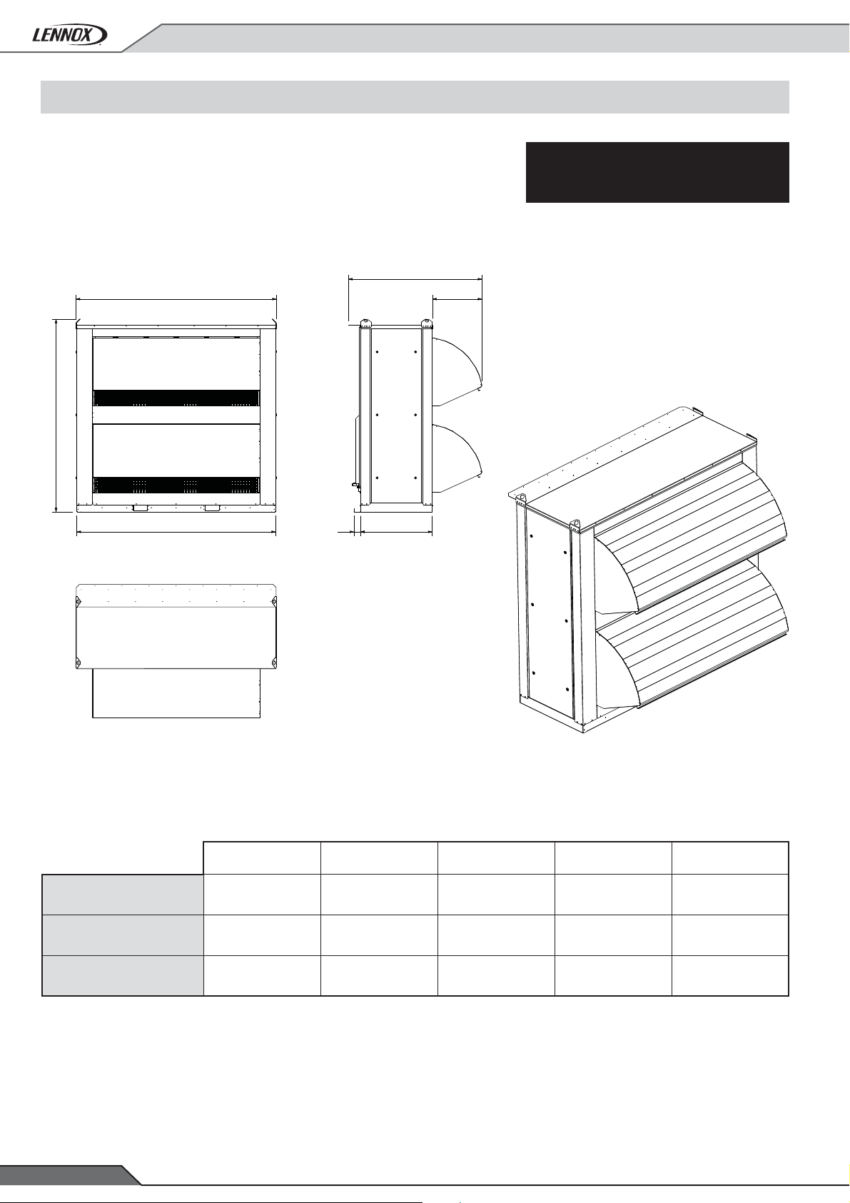
11- DIMENSIONS
11- HEAT RECOVERY OPTION IMENION
ENERGY RECOVERY OPTION
D
A
C
B 90083
E
FAC/FAH/FAG/FAM
85-100-120
150-170
200-230
• 74 •
DIMENSIONS
ABCDE
2146 2063 1796 1422 367
2330 2247 2170 1676 463
2516 2497 2418 1518 623
Application Guide / FLEXAIR-AGU-1505-E
Page 77

12- OPTIONS WEIGHT AND PRESSURE DROPS
12.1- OPTIONS WEIGHTS
SIZE
Basic unit
Airfl ow confi guration
High pressure EC Plug Fan
Exhaust air options
Gravity exhaust damper for downfl ow return
Power exhaust fan axial + gravity exhaust damper
(downfl ow return)
Heat recovery module
(downfl ow and horizontal fl ow)
EC Low Pressure return roofcurb
Downfl ow
EC Low Pressure return roofcurb
Horizontalfl ow
FAC
FAH
FAG (S)
FAG (H)
FAM (S)
FAM (H)
85 100 120 150 170 200 230
966 1055 1054 1454 1550 2027 2143
981 1070 1069 1484 1580 2057 2173
1013 1117 1108 1576 1681 2257 2371
1083 1187 1178 1599 1704 2297 2411
1028 1132 1123 1606 1711 2287 2401
1098 1202 1193 1629 1734 2327 2441
27 27 27 41 41 45 45
14 14 14 19 19 21 21
41 41 41 63 63 67 67
525 525 525 635 635 730 730
654 654 654 775 775 775 775
586 586 586 698 698 698 698
Filtration option
G4 metallic frame, whashable fi lter
F7 Filters / G4 Prefi lters
G4 Refi lable fi lters
Heating options versus FAC or FAG
2 steps electric heater
Modulating electric heater
Hot water coil
Other Options
Non adjustable non assembled roofcurb
Adjustable assembled roofcurb
36 36 36 44 44 61 61
6 6 6 11 11 19 19
6 6 6 11 11 19 19
S47474757577878
M6464647878103103
H 78 78 78 103 103 143 143
S34343452526363
H6262629696116116
94 94 94 108 108 128 128
197 197 197 229 229 272 272
Multi direction horizontalfl ow curb
S
Standard heat
M
Medium heat
H
High heat
Application Guide /FLEXAIR-AGU-1505-E
237 237 237 332 332 395 395
• 75 •
Page 78

12- ACCESSORIES PRESSURE DROPS
Cooling only Heat pump
FAC FAH
Cooling only with gas fi red heating Heat pump rooftop with gas fi red heating
FAG FAM
Airfl ow rate Filters Hot water coil
Size
85
100
120
150
170
200
230
m3/h
12000 1 75 9 15
15000 7 105 13 22
23000 28 199 26 44
14000 5 94 11 19
18500 15 143 18 31
23000 28 199 26 44
15000 7 105 13 22
20500 21 167 21 37
23000 28 199 26 44
18000 1 75 6 10
26000 12 130 12 19
35000 29 204 19 33
21000 5 94 8 14
30000 19 161 15 25
35000 29 204 19 33
24000 3 88 7 11
35000 18 154 13 22
43000 31 211 19 31
27000 7 105 8 14
39000 24 182 16 26
43000 31 211 19 31
G4 F7 S H
Size
85
100
120
150
170
200
230
Airfl ow rate Electric heater
m3/h
12000 3 5 6 14 17 22 161
15000 6 7 7 23 27 33 201
23000 7 9 11 53 63 73 309
14000 6 7 8 20 23 30 187
18500 8 10 11 34 41 51 248
23000 11 14 16 53 63 78 309
15000 7 8 9 23 27 35 201
20500 10 12 13 42 50 62 276
23000 12 15 17 53 63 78 309
18000 4 5 7 16 30 35 167
26000 9 10 13 33 62 72 241
35000 15 18 23 59 112 131 325
21000 8 9 10 21 40 49 194
30000 10 13 15 44 82 95 278
35000 17 19 21 59 112 131 325
24000 16 15 14 21 53 67 171
35000 22 21 20 44 112 133 250
43000 24 26 29 66 169 195 307
27000 18 18 17 26 67 84 192
39000 24 24 25 55 139 163 278
43000 24 26 29 66 169 195 307
SMH H
Heating gas
fi red
Adjustable
roofcurb
Multidirectio-
nal roofcurb
Heat recovery
module
Fresh air
• 76 •
Application Guide / FLEXAIR-AGU-1505-E
Page 79

Page 80
SALES OFFICES :
lennoxemeia.com
BELGIUM AND LUXEMBOURG
+ 32 3 633 3045
FRANCE
+33 1 64 76 23 23
GERMANY
+49 (0) 211 950 79 600
ITALY
+ 39 02 495 26 200
NETHERLANDS
+ 31 332 471 800
POLAND
+48 22 58 48 610
RUSSIA
+7 495 626 56 53
SPAIN
+34 915 401 810
UKRAINE
+38 044 585 59 10
UNITED KINGDOM AND IRELAND
+44 1604 669 100
OTHER COUNTRIES :
PORTUGAL
+351 229 066 050
FLEXAIR-AGU-1505-E
LENNOX DISTRIBUTION
+33 4 72 23 20 20
Due to Lennox’s ongoing commitment to quality , the specifi cations,
ratings and dimensions are subject to change without notice and
without incurring liability.
Improper installation, adjustment, alteration, service or
maintenance can cause property damage or personal injury.
Installation and service must be performed by a qualifi ed installer
and servicing agency
 Loading...