

Lennox ELS SERIES, ELS120S4S, ELS120S4D, ELS090S4S, ELS072S4S Unit Information
...
UNIT INFORMATION
Corp. 1811-L3
Service Literature
May 15, 2018
ELS SERIES UNITS
The ELS units are designed for light commercial applications, with a remotely located blower-coil unit or a furnace
with an add-on evaporator coil. Capacities for the series
are 6, 7-1/2, 10, 12.5, 15 and 20 tons (21, 26, 35, 44,
53, and 70 kW).ELS072, ELS090 and ELS120S4S models have one dual-speed scroll compressor. ELS120S4D,
ELS150S4D, ELS180S4D and ELS240S4D models have
two single-speed scroll compressors. ELS units match
with the ELA blower-coil units. All ELS units are three
phase and use HFC-410A refrigerant.
This manual covers ELS072S4S, ELS090S4S,
ELS120S4S, ELS120S4D, ELS150S4D, ELS180S4D and
ELS240S4D units. It is divided into sections which discuss
the major components, refrigerant system, charging procedure, maintenance and operation sequence.
Information in this manual is intended for qualied service
technicians only. All specications are subject to change.
Procedures in this manual are presented as a recommendation only and do not supersede or replace local or state
codes.
WARNING
Improper installation, adjustment, alteration, service
or maintenance can cause property damage, personal
injury or loss of life. Installation and service must be
performed by a licensed professional HVAC installer or
equivalent, service agency, or the gas supplier.
IMPORTANT
The Clean Air Act of 1990 bans the intentional venting of
refrigerant (CFCs, HCFCs and HFCs) as of July 1, 1992.
Approved methods of recovery, recycling or reclaiming
must be followed. Fines and/or incarceration may be
levied for noncompliance.
WARNING
Electric shock hazard! - Disconnect all power
supplies before servicing.
Replace all parts and panels before
operating.
Failure to do so can result in death or
electrical shock.
ELS
6 - 20 TON
Table of Contents
Unit Plumbing Parts Arrangement .................................5
Model Number Identication ........................................ 10
Unit Control Box Components Arrangement ................11
I-UNIT COMPONENTS ................................................12
A-CONTROL BOX COMPONENTS ............................12
B-COOLING COMPONENTS .......................................12
II- REFRIGERANT SYSTEM ....................................... 13
A-Plumbing .................................................................. 13
B-Service Valves ......................................................... 14
III-START-UP ................................................................15
IV-CHARGING ..............................................................16
A-Leak Testing .............................................................. 16
B-Evacuating the System .............................................17
C-Charging ...................................................................18
V-MAINTENANCE ........................................................22
VI-Wiring Diagram and Sequence of Operation ........... 23
CAUTION
As with any mechanical equipment, contact with sharp
sheet metal edges can result in personal injury. Take
care while handling this equipment and wear gloves and
protective clothing.
Page 1
SPECIFICATIONS - 6 - 7.5 TON
67
32
53
3(
71
46
23
3(
22
Refer to National or Canadian Electrical Code manual to determine wire, fuse and disconnect size requirements.
General
Data
Connections
(sweat)
Nominal Size - Tons
Liquid line - in. (o.d) (1)3/8 (1)5/8
Suction line - in. (o.d) (1)1-1/8 (1)1-1/8
Refrigerant
(R-410A)
1
Field charge (25 ft. line set) 18 lbs. 0 oz.20 lbs. 0 oz.
Compressor (1) Two-Stage Scroll (1)Two-Stage Scroll
Condenser
Net face area - sq. ft. Outer coil 29.
Coil
Tube diameter - in. & no. of rows 3/8 - 1.
Condenser
Diameter - in. & no. of blades (1) 24 -
Fan(s)
Total air volume - cfm 4700 5600
ELECTRICAL DATA
Line voltage data - 60 hz - 3 phase 208/230V 460V 575V 208/230V 460V 575V
2
Maximum Overcurrent Protection (amps) 40 15 15 60 25 20
Compressor No. of Compressors 111111
Condenser
Fan Motor
(1 phase)
NOTE - Extremes of operating range are plus and minus 10% of line voltage.
1
Field provided charge with 25 ft. line set. Refer to the Lennox Refrigerant Piping Manual to determine refrigerant charge required with longer length refrigerant lines.
2
HACR type circuit breaker or fuse.
3
Refer to National or Canadian Electrical Code manual to determine wire, fuse and disconnect size requirements.
3
Minimum circuit ampacity 24 12 9371
Model No. ELS072S4S ELS090S4S
.5
Factory Charge R-410A holding charge (2 lbs. per stage)
9.3
Inner coil 14.2 28.4
/8 - 2
Fins per inch 20 20
1) 24 - 4
Motor hp (1)1/3 (1)1/2
Rpm 1075 1075
Watts 400 580
Rated load amps 17.6 8.56.3 26.9 12 9
Locked rotor amps 136 66 55 1659
No. of motors 111111
Full load amps 1.7 0.81 31.5 1.2
Locked rotor amps 4.3 2.41.9 63
2.9
3
5
SPECIFICATIONS - 10 TON
General
Data
Connections
(sweat)
Nominal Size - Tons 10 10
Liquid line - in. (o.d) (1)5/8 (2)3/8
Suction line - in. (o.d) (1)1-1/8 (2)1-1/8
Refrigerant
(R-410A)
1
Field charge
(25 ft. line set)
Compressor (1) Two-Stage Scroll (2)Single-Stage Scroll
Condenser
Net face area - sq. ft. Outer coil 29.3 29.3
Coil
Tube diameter - in. & no. of rows 3/8 -
Condenser
Diameter - in. & no. of blades (2) 24 -
Fan(s)
Total air volume - cfm 8300 8300
ELECTRICAL DATA
Line voltage data - 60 hz - 3 phase 208/230V 460V 575V 208/230V 460V 575V
2
Maximum Overcurrent Protection (amps) 80 30 25 40 20 15
Compressor No. of Compressors 1112
Condenser
Fan Motor
(1 phase)
NOTE - Extremes of operating range are plus and minus 10% of line voltage.
1
Field provided charge with 25 ft. line set. Refer to the Lennox Refrigerant Piping Manual to determine refrigerant charge required with longer length refrigerant lines.
2
HACR type circuit breaker or fuse.
3
3
Minimum circuit ampacity 47 21 16 30 16 13
Rated load amps (total) 34.6 14.8 11 .1 12 (24) 6.3 (12.6) 4.9 (9.8)
Locked rotor amps (total) 240 13094 90 (180) 60 (120) 41 (82)
Full load amps (total) 1.7 (3.4) 0.8 (1.6)1 (2)1.7 (3.4)0.8 (1.6)1 (2)
Locked rotor amps (total) 4.3 (8.6) 2.4 (4.8)1.9 (3.8)4.3 (8.6)2.4 (4.8)1.9 (3.8)
Model No. ELS120S4S ELS120S4D
Factory Charge R-410A holding charge (2 lbs. per stage)
Circuit 1 32 lbs. 0 oz. 12 lbs. 0 oz.
Circuit 2- - - 12 lbs. 0 oz.
Inner coil 28.4 28.4
/8 - 2
Fins per inch 20 20
2) 24 - 3
Motor hp (2)1/3 (2)1/3
Rpm 1075 1075
Watts 830 830
No. of motors 222222
Page 2
SPECIFICATIONS - 12.5 - 20 TON
52
23
tS
.k
04
General
Data
Connections
(sweat)
Nominal Size - Tons 12.51
Liquid line - in. (o.d) (2)3/8 (2)5/8 (2)5/8
Suction line - in. (o.d) (2)1-1/8 (2)1-1/8 (2)1-1/8
Refrigerant
(R-410A)
1
Field charge
(25 ft. line set)
Compressor (2) Single-Stage Scroll (2)Single-Stage Scroll (2)Single-Stage Scroll
Condenser
Net face area - sq. ft. Outer coil 34.2 58.7 58.7
Coil
Tube diameter - in. & no. of rows 3/8 - 23/8 -
Condenser
Diameter - in. & no. of blades (2)24 - 4(4) 24 - 3(4) 24 - 3
Fan(s)
Total air volume - cfm 10,300 16,600 16,600
Model No. ELS150S4D ELS180S4D ELS240S4D
Factory Charge R-410A holding charge (2 lbs. per stage)
Circuit 1 15 lbs. 0 oz. 24 lbs. 0 oz.22 lbs. 4 oz.
Circuit 2 15 lbs. 0 oz. 24 lbs. 0 oz.23 lbs. 3 oz.
Inner coil 33.3 57.7 57.7
Fins per inch 20 20 20
Motor hp (2)1/2 (4)1/3 (4)1/3
Rpm 1075 1075 1075
Watts 1130 1660 1660
0
/8 - 2
ELECTRICAL DATA
Line voltage data - 60 hz - 3 phase 208/230V 460V 575V 208/230V 460V 575V 208/230V 460V 575V
2
Maximum Overcurrent Protection (amps) 60 25 25 80 40 30 90 50 40
3
Minimum circuit ampacity 50 21 20 63 31 25 70 36 30
Compressor No. of Compressors 222222222
Rated load amps
(total)
Locked rotor amps
(total)
Condenser
Fan Motor
(1 phase)
No. of motors 222444444
Full load amps
(total)3 (6)
Locked rotor amps
(total)6 (12)
NOTE - Extremes of operating range are plus and minus 10% of line voltage.
1
Field provided charge with 25 ft. line set. Refer to the Lennox Refrigerant Piping Manual to determine refrigerant charge required with longer length refrigerant lines.
2
HACR type circuit breaker or fuse.
3
Refer to National or Canadian Electrical Code manual to determine wire, fuse and disconnect size requirements.
19.6
(39.2)
136
(272)
8.2
(16.4)
66
(132)
1.5
(3)
(6)
6.6
(13.2)
55
(110)
1.2
(2.4)
3
2.9
(5.8)
25
(50)
164
(328)
1.7
(6.8)
4.3
(17.2)
12.2
(24.4)9 (18)
100
(200)
78
(156)
0.8
(3.2)1 (4)
2.4
(9.6)
1.9
(7.6)
28.2
(56.4)
240
(480)
1.7
(6.8)
4.3
(17.2)
14.7
(29.4)
130
(260)
11.3
(22.6)
93.7
(187.4)
0.8
(3.2)1 (4)
2.4
(9.6)
(7.6)
1.9
WEIGHT DATA
Model No. Ne
lbs.kglbs
072S 318 144 338 153
090S 345 157365 166
120S 452 205 477 216
120D 480 218 505 229
150S 535 243560 254
180S 775 352 800 363
240S 832 377 857 389
hipping
OPTIONS / ACCESSORIES
COMBINED COIL/HAIL GUARDS
T2GARD20L-1 40 18 45 20
T2GARD20M-1 45 20 50 23
T2GARD21M-1 45 20 50 23
T2GARD20N-1- 90 41 10
Page 3
g
5

OPTIONS / ACCESSORIES
CABINET
Combined Coil/Hail Guards
XX
Corrosion Protection
OOOOOOO
XXXXXXX
XXXXXXX
XXXXXXX
XXXXXXX
XXXXXX
Low
XX
XXXXXXX
XXXXXXX
XXXXXXX
XXXXXXX
XXXXXXX
XXXXXXX
XXXXXXX
sensor (77N39)
XXXXXXX
CONTROLS
BACnet
BACnet
BACnet
Network Thermostat Control (NTC) C0CTRL07AE1L 17M10 XXXXXXX
NTC Enclosure Kit (required with NTC Controller) A0CTRL32LS1 16H99
L Connection
ELECTRICAL
GFI
Service
Outlets
INDOOR AIR QUALITY
Sensor - Wall-mount, off-white plastic cover with LCD display C0SNSR50AE1L 77N39
Sensor - Wall-mount, off-white plastic cover, no display C0SNSR52AE1L 87N53
Sensor - Black plastic case with LCD display, rated for
plenum mounting
Sensor - Wall-mount, black plastic case, no display, rated for
plenum mounting
CO
Aspiration Box - for duct mounting non-plenum rated CO
®
Module A0CTRL31LS1 17A08
®
Sensor with Display K0SNSR01FF1 97W23
®
Sensor without Display K0SNSR00FF1 97W24
®
Ambient Control (0ºF) A2CWKT01LM1- 16F18 XX
Sensor Duct Mounting Kit C0MISC19AE1- 85L43
2
Item Catalog
No.
ELS
072
S4S
T2GARD51L-1 13T29 XX
T2GARD51M11 13T30 XX
T2GARD51M21 13T32 X
T2GARD51N-1 13T37
Factory
Building Automation System - - - X
A2CWKT04M-1- 16F26 X
A2CWKT02M-1- 16F24 XX
A2CWKT03N-1- 16F25
74M70
(208/230V, 460V only) LTAGFIK10/15/15
67E01
C0SNSR51AE1L 87N52
C0SNSR53AE1L 87N54
2
C0MISC16AE1- 90N43
ELS
090
S4S
ELS
120
S4S
ELS
ELS
120
150
S4D
S4D
ELS
180
S4D
ELS
240
S4D
O - Factory Installed with extended lead time.
X - Field Installed
Page 4
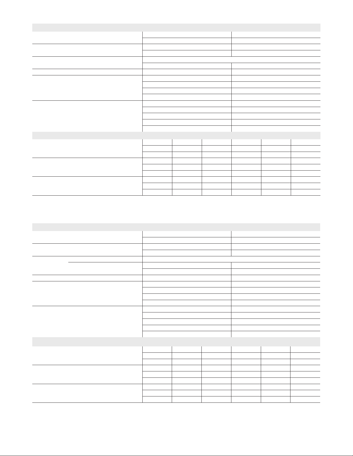
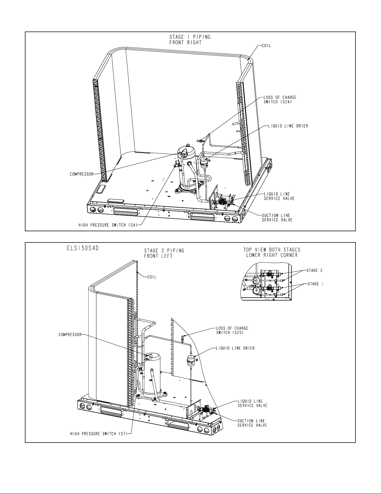
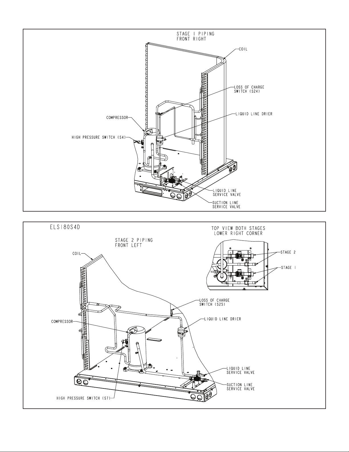
Unit Plumbing Parts Arrangement
ELS072S4S
ELS090S4S
Page 5
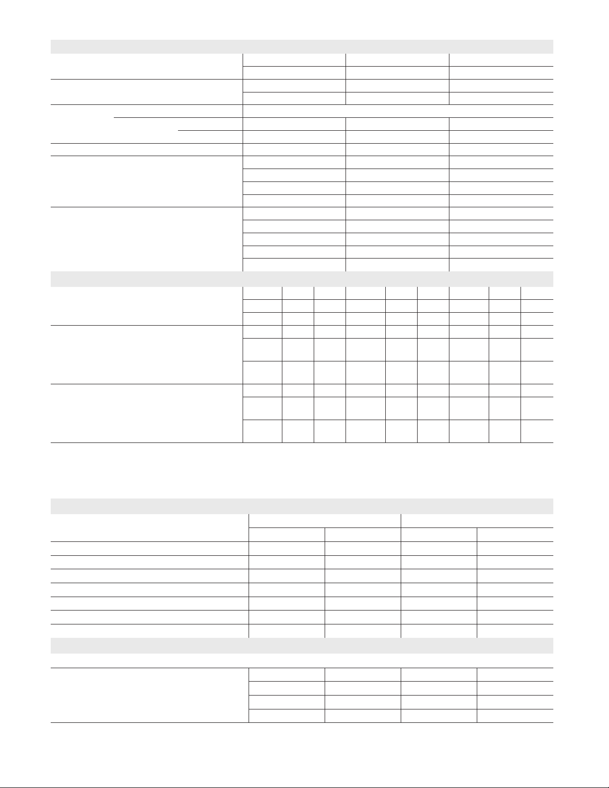
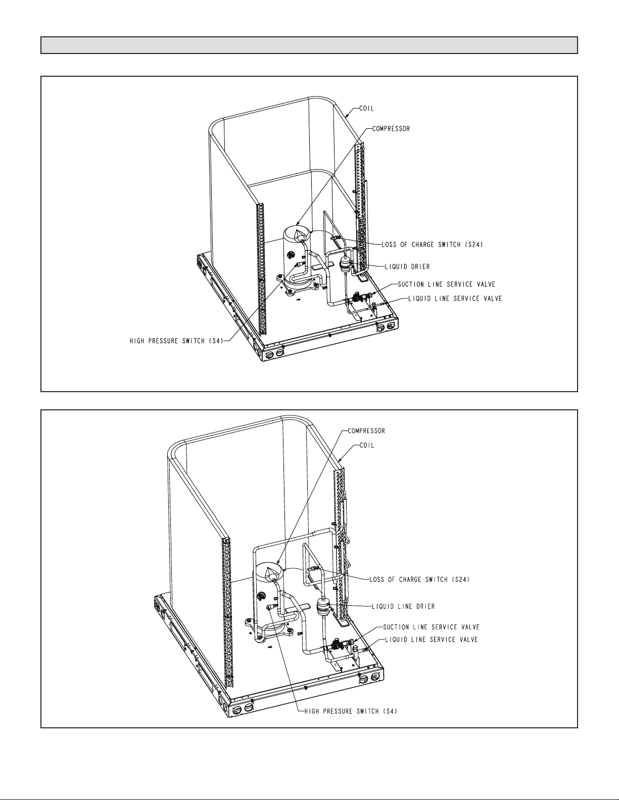
ELS120S4S
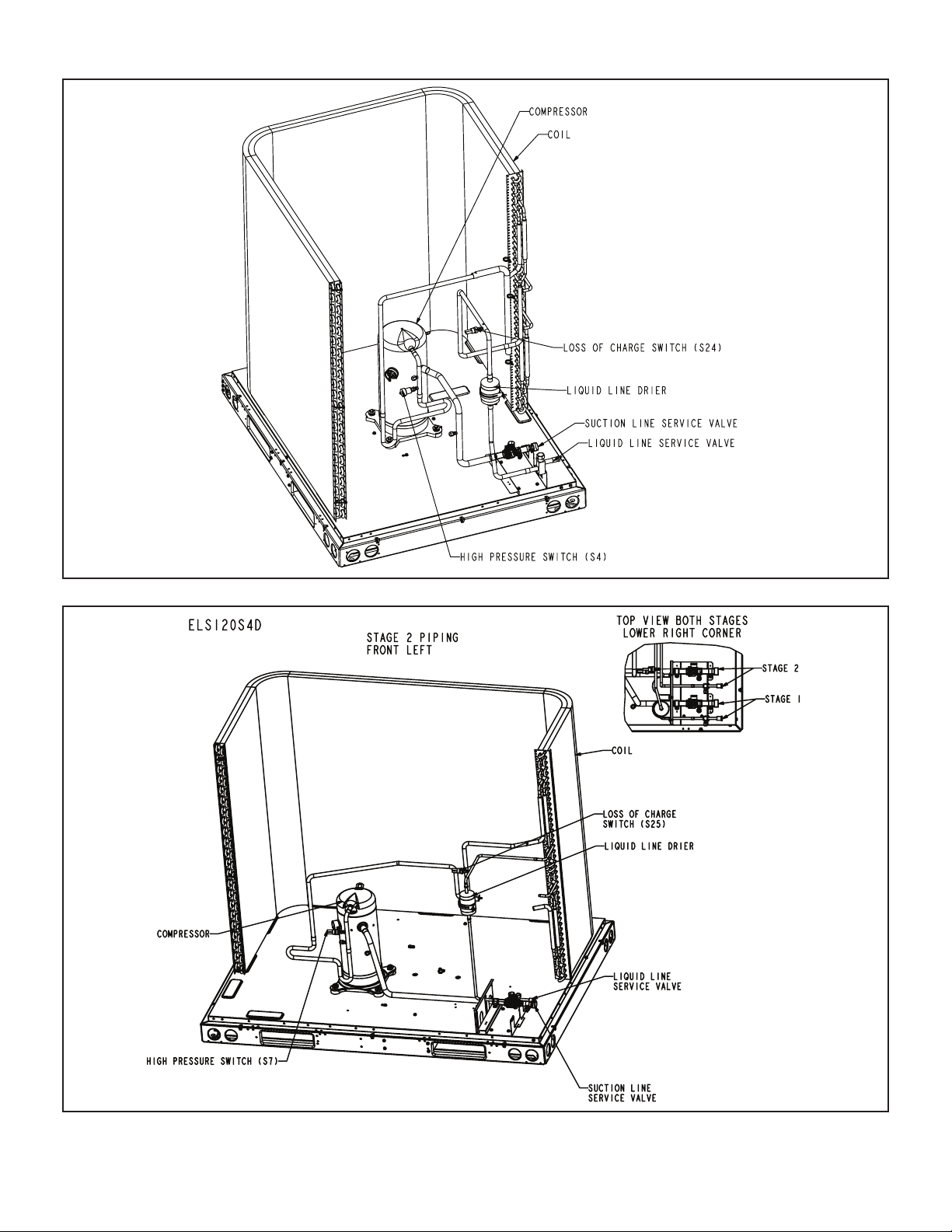
ELS120S4D – STAGE 2
Page 6
ELS120S4D – STAGE 1
ELS150S4D – STAGE 2
Page 7
ELS150S4D – STAGE 1
ELS180S4D – STAGE 2
Page 8
 Loading...