

Page 1

UNIT INFORMATION
Corp. 1811-L3
Service Literature
May 15, 2018
ELS SERIES UNITS
The ELS units are designed for light commercial applications, with a remotely located blower-coil unit or a furnace
with an add-on evaporator coil. Capacities for the series
are 6, 7-1/2, 10, 12.5, 15 and 20 tons (21, 26, 35, 44,
53, and 70 kW).ELS072, ELS090 and ELS120S4S models have one dual-speed scroll compressor. ELS120S4D,
ELS150S4D, ELS180S4D and ELS240S4D models have
two single-speed scroll compressors. ELS units match
with the ELA blower-coil units. All ELS units are three
phase and use HFC-410A refrigerant.
This manual covers ELS072S4S, ELS090S4S,
ELS120S4S, ELS120S4D, ELS150S4D, ELS180S4D and
ELS240S4D units. It is divided into sections which discuss
the major components, refrigerant system, charging procedure, maintenance and operation sequence.
Information in this manual is intended for qualied service
technicians only. All specications are subject to change.
Procedures in this manual are presented as a recommendation only and do not supersede or replace local or state
codes.
WARNING
Improper installation, adjustment, alteration, service
or maintenance can cause property damage, personal
injury or loss of life. Installation and service must be
performed by a licensed professional HVAC installer or
equivalent, service agency, or the gas supplier.
IMPORTANT
The Clean Air Act of 1990 bans the intentional venting of
refrigerant (CFCs, HCFCs and HFCs) as of July 1, 1992.
Approved methods of recovery, recycling or reclaiming
must be followed. Fines and/or incarceration may be
levied for noncompliance.
WARNING
Electric shock hazard! - Disconnect all power
supplies before servicing.
Replace all parts and panels before
operating.
Failure to do so can result in death or
electrical shock.
ELS
6 - 20 TON
Table of Contents
Unit Plumbing Parts Arrangement .................................5
Model Number Identication ........................................ 10
Unit Control Box Components Arrangement ................11
I-UNIT COMPONENTS ................................................12
A-CONTROL BOX COMPONENTS ............................12
B-COOLING COMPONENTS .......................................12
II- REFRIGERANT SYSTEM ....................................... 13
A-Plumbing .................................................................. 13
B-Service Valves ......................................................... 14
III-START-UP ................................................................15
IV-CHARGING ..............................................................16
A-Leak Testing .............................................................. 16
B-Evacuating the System .............................................17
C-Charging ...................................................................18
V-MAINTENANCE ........................................................22
VI-Wiring Diagram and Sequence of Operation ........... 23
CAUTION
As with any mechanical equipment, contact with sharp
sheet metal edges can result in personal injury. Take
care while handling this equipment and wear gloves and
protective clothing.
Page 1
Page 2
SPECIFICATIONS - 6 - 7.5 TON
67
32
53
3(
71
46
23
3(
22
Refer to National or Canadian Electrical Code manual to determine wire, fuse and disconnect size requirements.
General
Data
Connections
(sweat)
Nominal Size - Tons
Liquid line - in. (o.d) (1)3/8 (1)5/8
Suction line - in. (o.d) (1)1-1/8 (1)1-1/8
Refrigerant
(R-410A)
1
Field charge (25 ft. line set) 18 lbs. 0 oz.20 lbs. 0 oz.
Compressor (1) Two-Stage Scroll (1)Two-Stage Scroll
Condenser
Net face area - sq. ft. Outer coil 29.
Coil
Tube diameter - in. & no. of rows 3/8 - 1.
Condenser
Diameter - in. & no. of blades (1) 24 -
Fan(s)
Total air volume - cfm 4700 5600
ELECTRICAL DATA
Line voltage data - 60 hz - 3 phase 208/230V 460V 575V 208/230V 460V 575V
2
Maximum Overcurrent Protection (amps) 40 15 15 60 25 20
Compressor No. of Compressors 111111
Condenser
Fan Motor
(1 phase)
NOTE - Extremes of operating range are plus and minus 10% of line voltage.
1
Field provided charge with 25 ft. line set. Refer to the Lennox Refrigerant Piping Manual to determine refrigerant charge required with longer length refrigerant lines.
2
HACR type circuit breaker or fuse.
3
Refer to National or Canadian Electrical Code manual to determine wire, fuse and disconnect size requirements.
3
Minimum circuit ampacity 24 12 9371
Model No. ELS072S4S ELS090S4S
.5
Factory Charge R-410A holding charge (2 lbs. per stage)
9.3
Inner coil 14.2 28.4
/8 - 2
Fins per inch 20 20
1) 24 - 4
Motor hp (1)1/3 (1)1/2
Rpm 1075 1075
Watts 400 580
Rated load amps 17.6 8.56.3 26.9 12 9
Locked rotor amps 136 66 55 1659
No. of motors 111111
Full load amps 1.7 0.81 31.5 1.2
Locked rotor amps 4.3 2.41.9 63
2.9
3
5
SPECIFICATIONS - 10 TON
General
Data
Connections
(sweat)
Nominal Size - Tons 10 10
Liquid line - in. (o.d) (1)5/8 (2)3/8
Suction line - in. (o.d) (1)1-1/8 (2)1-1/8
Refrigerant
(R-410A)
1
Field charge
(25 ft. line set)
Compressor (1) Two-Stage Scroll (2)Single-Stage Scroll
Condenser
Net face area - sq. ft. Outer coil 29.3 29.3
Coil
Tube diameter - in. & no. of rows 3/8 -
Condenser
Diameter - in. & no. of blades (2) 24 -
Fan(s)
Total air volume - cfm 8300 8300
ELECTRICAL DATA
Line voltage data - 60 hz - 3 phase 208/230V 460V 575V 208/230V 460V 575V
2
Maximum Overcurrent Protection (amps) 80 30 25 40 20 15
Compressor No. of Compressors 1112
Condenser
Fan Motor
(1 phase)
NOTE - Extremes of operating range are plus and minus 10% of line voltage.
1
Field provided charge with 25 ft. line set. Refer to the Lennox Refrigerant Piping Manual to determine refrigerant charge required with longer length refrigerant lines.
2
HACR type circuit breaker or fuse.
3
3
Minimum circuit ampacity 47 21 16 30 16 13
Rated load amps (total) 34.6 14.8 11 .1 12 (24) 6.3 (12.6) 4.9 (9.8)
Locked rotor amps (total) 240 13094 90 (180) 60 (120) 41 (82)
Full load amps (total) 1.7 (3.4) 0.8 (1.6)1 (2)1.7 (3.4)0.8 (1.6)1 (2)
Locked rotor amps (total) 4.3 (8.6) 2.4 (4.8)1.9 (3.8)4.3 (8.6)2.4 (4.8)1.9 (3.8)
Model No. ELS120S4S ELS120S4D
Factory Charge R-410A holding charge (2 lbs. per stage)
Circuit 1 32 lbs. 0 oz. 12 lbs. 0 oz.
Circuit 2- - - 12 lbs. 0 oz.
Inner coil 28.4 28.4
/8 - 2
Fins per inch 20 20
2) 24 - 3
Motor hp (2)1/3 (2)1/3
Rpm 1075 1075
Watts 830 830
No. of motors 222222
Page 2
Page 3
SPECIFICATIONS - 12.5 - 20 TON
52
23
tS
.k
04
General
Data
Connections
(sweat)
Nominal Size - Tons 12.51
Liquid line - in. (o.d) (2)3/8 (2)5/8 (2)5/8
Suction line - in. (o.d) (2)1-1/8 (2)1-1/8 (2)1-1/8
Refrigerant
(R-410A)
1
Field charge
(25 ft. line set)
Compressor (2) Single-Stage Scroll (2)Single-Stage Scroll (2)Single-Stage Scroll
Condenser
Net face area - sq. ft. Outer coil 34.2 58.7 58.7
Coil
Tube diameter - in. & no. of rows 3/8 - 23/8 -
Condenser
Diameter - in. & no. of blades (2)24 - 4(4) 24 - 3(4) 24 - 3
Fan(s)
Total air volume - cfm 10,300 16,600 16,600
Model No. ELS150S4D ELS180S4D ELS240S4D
Factory Charge R-410A holding charge (2 lbs. per stage)
Circuit 1 15 lbs. 0 oz. 24 lbs. 0 oz.22 lbs. 4 oz.
Circuit 2 15 lbs. 0 oz. 24 lbs. 0 oz.23 lbs. 3 oz.
Inner coil 33.3 57.7 57.7
Fins per inch 20 20 20
Motor hp (2)1/2 (4)1/3 (4)1/3
Rpm 1075 1075 1075
Watts 1130 1660 1660
0
/8 - 2
ELECTRICAL DATA
Line voltage data - 60 hz - 3 phase 208/230V 460V 575V 208/230V 460V 575V 208/230V 460V 575V
2
Maximum Overcurrent Protection (amps) 60 25 25 80 40 30 90 50 40
3
Minimum circuit ampacity 50 21 20 63 31 25 70 36 30
Compressor No. of Compressors 222222222
Rated load amps
(total)
Locked rotor amps
(total)
Condenser
Fan Motor
(1 phase)
No. of motors 222444444
Full load amps
(total)3 (6)
Locked rotor amps
(total)6 (12)
NOTE - Extremes of operating range are plus and minus 10% of line voltage.
1
Field provided charge with 25 ft. line set. Refer to the Lennox Refrigerant Piping Manual to determine refrigerant charge required with longer length refrigerant lines.
2
HACR type circuit breaker or fuse.
3
Refer to National or Canadian Electrical Code manual to determine wire, fuse and disconnect size requirements.
19.6
(39.2)
136
(272)
8.2
(16.4)
66
(132)
1.5
(3)
(6)
6.6
(13.2)
55
(110)
1.2
(2.4)
3
2.9
(5.8)
25
(50)
164
(328)
1.7
(6.8)
4.3
(17.2)
12.2
(24.4)9 (18)
100
(200)
78
(156)
0.8
(3.2)1 (4)
2.4
(9.6)
1.9
(7.6)
28.2
(56.4)
240
(480)
1.7
(6.8)
4.3
(17.2)
14.7
(29.4)
130
(260)
11.3
(22.6)
93.7
(187.4)
0.8
(3.2)1 (4)
2.4
(9.6)
(7.6)
1.9
WEIGHT DATA
Model No. Ne
lbs.kglbs
072S 318 144 338 153
090S 345 157365 166
120S 452 205 477 216
120D 480 218 505 229
150S 535 243560 254
180S 775 352 800 363
240S 832 377 857 389
hipping
OPTIONS / ACCESSORIES
COMBINED COIL/HAIL GUARDS
T2GARD20L-1 40 18 45 20
T2GARD20M-1 45 20 50 23
T2GARD21M-1 45 20 50 23
T2GARD20N-1- 90 41 10
Page 3
g
5
Page 4

OPTIONS / ACCESSORIES
CABINET
Combined Coil/Hail Guards
XX
Corrosion Protection
OOOOOOO
XXXXXXX
XXXXXXX
XXXXXXX
XXXXXXX
XXXXXX
Low
XX
XXXXXXX
XXXXXXX
XXXXXXX
XXXXXXX
XXXXXXX
XXXXXXX
XXXXXXX
sensor (77N39)
XXXXXXX
CONTROLS
BACnet
BACnet
BACnet
Network Thermostat Control (NTC) C0CTRL07AE1L 17M10 XXXXXXX
NTC Enclosure Kit (required with NTC Controller) A0CTRL32LS1 16H99
L Connection
ELECTRICAL
GFI
Service
Outlets
INDOOR AIR QUALITY
Sensor - Wall-mount, off-white plastic cover with LCD display C0SNSR50AE1L 77N39
Sensor - Wall-mount, off-white plastic cover, no display C0SNSR52AE1L 87N53
Sensor - Black plastic case with LCD display, rated for
plenum mounting
Sensor - Wall-mount, black plastic case, no display, rated for
plenum mounting
CO
Aspiration Box - for duct mounting non-plenum rated CO
®
Module A0CTRL31LS1 17A08
®
Sensor with Display K0SNSR01FF1 97W23
®
Sensor without Display K0SNSR00FF1 97W24
®
Ambient Control (0ºF) A2CWKT01LM1- 16F18 XX
Sensor Duct Mounting Kit C0MISC19AE1- 85L43
2
Item Catalog
No.
ELS
072
S4S
T2GARD51L-1 13T29 XX
T2GARD51M11 13T30 XX
T2GARD51M21 13T32 X
T2GARD51N-1 13T37
Factory
Building Automation System - - - X
A2CWKT04M-1- 16F26 X
A2CWKT02M-1- 16F24 XX
A2CWKT03N-1- 16F25
74M70
(208/230V, 460V only) LTAGFIK10/15/15
67E01
C0SNSR51AE1L 87N52
C0SNSR53AE1L 87N54
2
C0MISC16AE1- 90N43
ELS
090
S4S
ELS
120
S4S
ELS
ELS
120
150
S4D
S4D
ELS
180
S4D
ELS
240
S4D
O - Factory Installed with extended lead time.
X - Field Installed
Page 4
Page 5
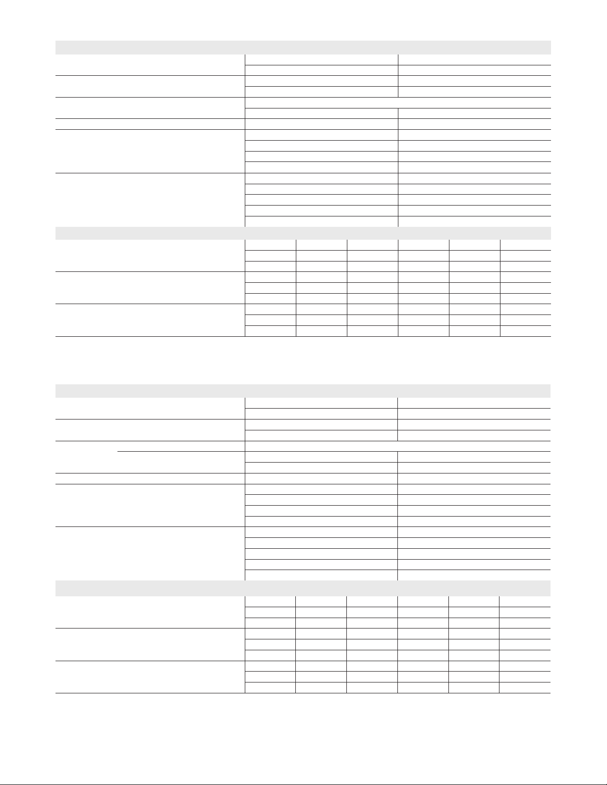
Unit Plumbing Parts Arrangement
ELS072S4S
ELS090S4S
Page 5
Page 6
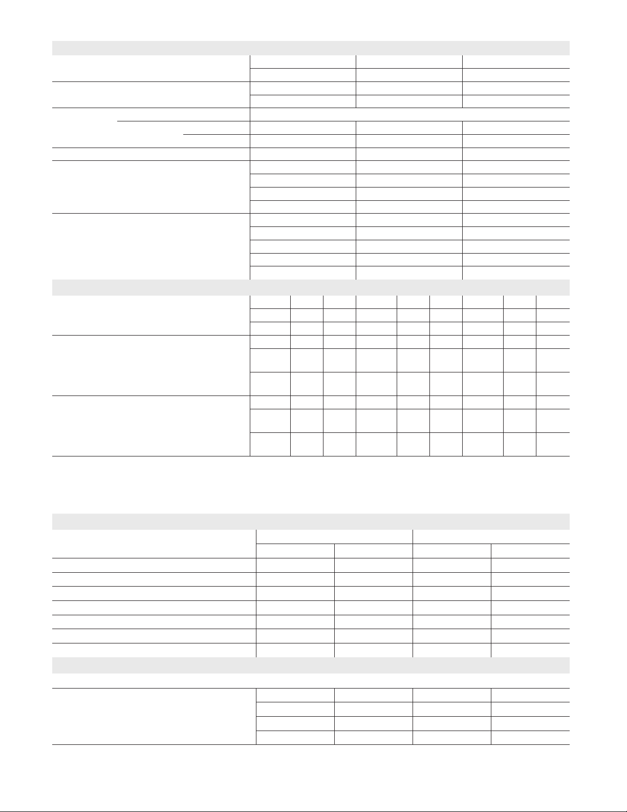
ELS120S4S
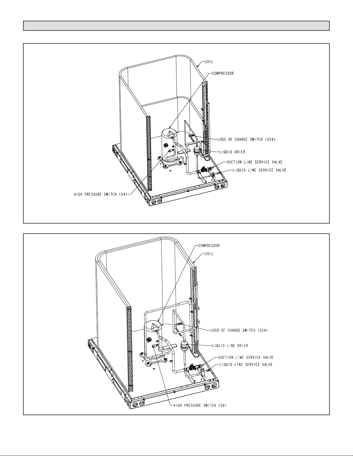
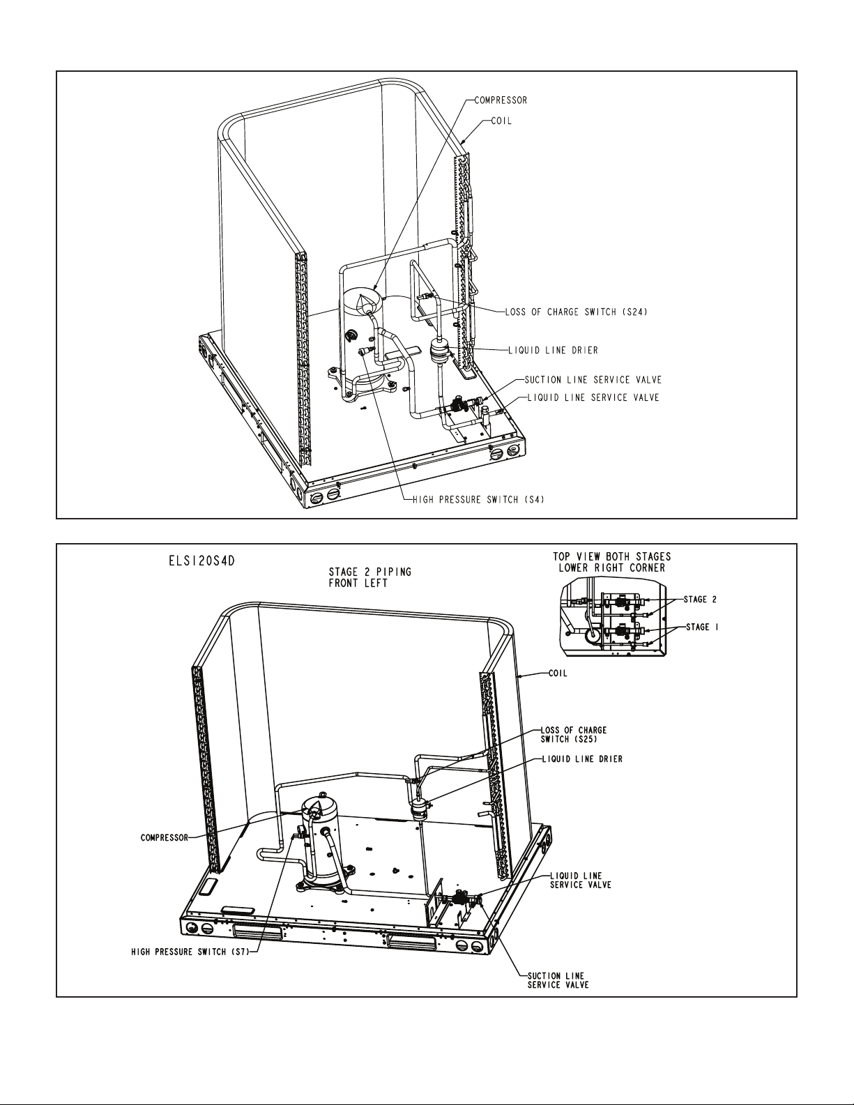
ELS120S4D – STAGE 2
Page 6
Page 7
ELS120S4D – STAGE 1
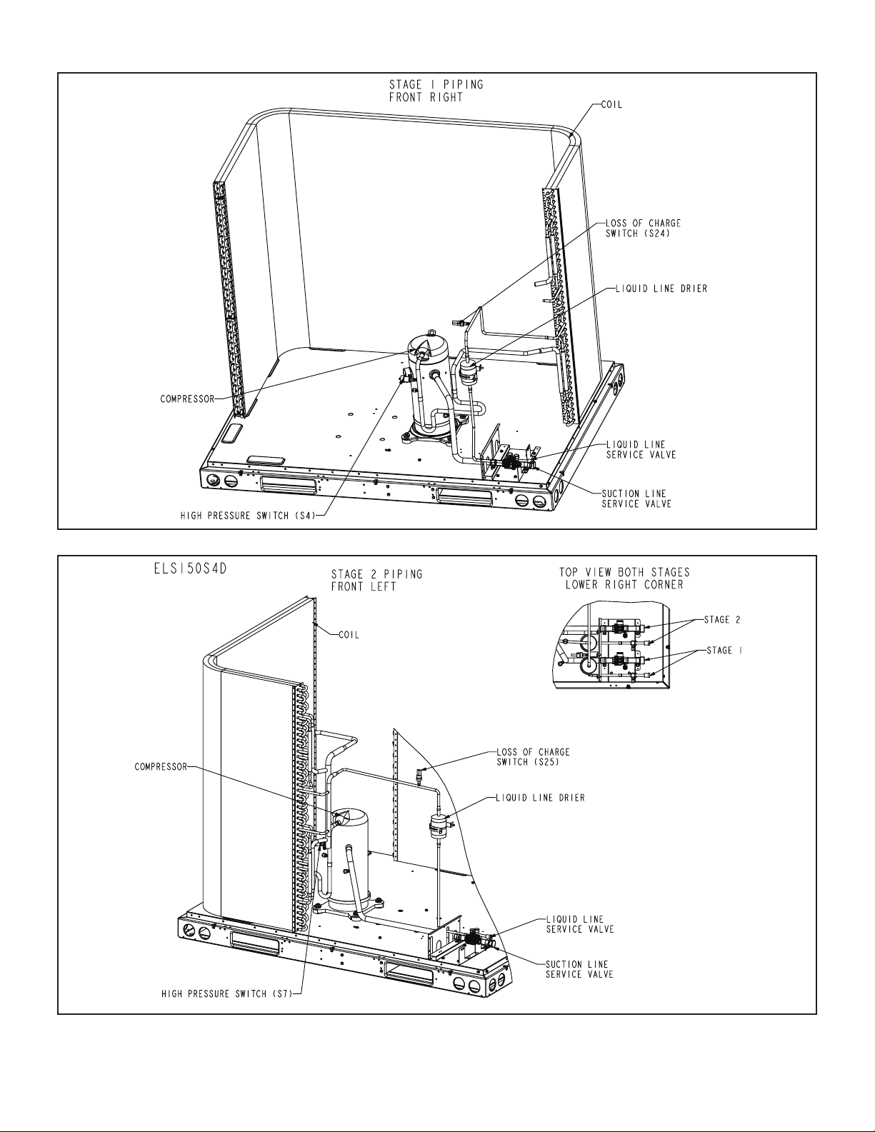
ELS150S4D – STAGE 2
Page 7
Page 8
ELS150S4D – STAGE 1
ELS180S4D – STAGE 2
Page 8
Page 9

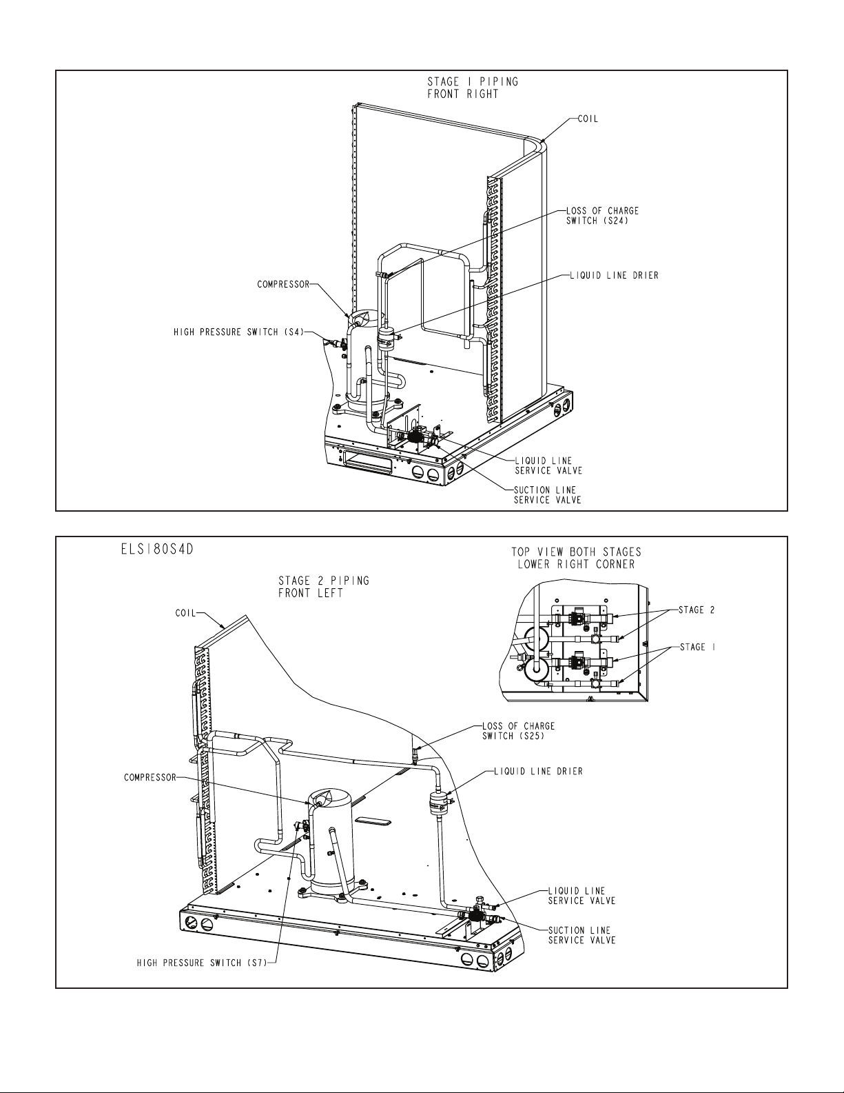
ELS180S4D – STAGE 1
ELS240S4D – STAGE 2
Page 9
Page 10

ELS240S4D – STAGE 1
ELSY1120 S S4 D
Model Number Identication
Brand/Family
Elite™ Product Line
S = Split System Air Conditioner
Nominal Cooling Capacity -
090 = 7.5 Tons
120 = 10 To ns
150 = 12.5 Tons
180 = 15 To ns
240 = 20 To ns
Tons
072 = 6 Tons
Minor Design Sequence
1 = 1st Revision
2 = 2nd Revision
3 = 3rd Revision
Part Load Capability
S = Single Stage Compressor
T = Two Stage Compressor
Refrigerant Circuits
S = Single Circuit
D = Dual Circuits
Refrigerant Type
4 = R-410A
Cooling Efficiency
S = Standard Efficiency
Voltage
Y = 208/230V‐3 phase‐60hz
G = 460V‐3 phase‐60hz
J = 575V‐3 phase‐60hz
M = 380/420V‐3 phase‐50hz
Page 10
Page 11

Unit Control Box Components Arrangement
ICM CONTROLLER
(FIELD INSTALLED)
ICM CONTROLLER
(FIELD INSTALLED)
TRANSFORMER
TRANSFORMER
ELS072/090S
ICM CONTROLLER
(FIELD INSTALLED)
TRANSFORMER
TRANSFORMER
ELS120S
ICM CONTROLLER
(FIELD INSTALLED)
CONTACTOR
ELS120D/ELS150D
CONTACTOR
ELS180D / ELS240D
Page 11
Page 12

I-UNIT COMPONENTS
ORANGE
BLACK
208/230V TRANSFORMER
The ELS parts arrangements are shown on pages 5 - 10
and control boxes on page 11.
WARNING
Electrostatic discharge can affect
electronic components. Take care
during unit installation and service to
ELECTROSTATIC
DISCHARGE
(ESD)
Precautions and
Procedures
A-CONTROL BOX COMPONENTS
1 - Transformer T1 & T18
All ELS models use a single line voltage to 24VAC transformer mounted in the control box. Transformer T1 supplies power to control circuits in the ELS unit. The transformer is rated at 70VA and is protected by a 3.5 amp
circuit breaker (CB8). CB8 is internal to the transformer.
The 208/230 (Y) voltage transformers use two primary
voltage taps as shown in gure 1, while 460 (G) and 575
(J) voltage transformers use a single primary voltage tap.
T18 is identical to T1 used in ELS120, 150, 180 and 240
and is protected by internal circuit breaker CB18.
NOTE – 208 volt units are eld wired with the red wire
connected to control transformer. 230 volt units are factory
wired with the orange wire connected to control transfomer primary.
2 - Terminal Strip TB14 & TB2
Terminal strip TB14 used in all units distributes 24V power
and common from the transformer T18 to the control box
components. Terminal block TB2 used in the 120, 150,
180 and 240 units, distributes line voltage to line voltage
components.
3 - Condenser Fan Capacitors C1, C2, C18, C19
All ELS units use single-phase condenser fan motors. Motors are equipped with a fan run capacitor to maximize
motor efciency. Condenser fan capacitors C1, C2, C18
and C19 assist in the start up of condenser fan motors B4,
B5, B21 and B22. Capacitor ratings will be on condenser
fan motor nameplate.
protect the unit’s electronic controls.
Precautions will help to avoid control
exposure to electrostatic discharge
by putting the unit, the control and the
technician at the same electrostatic
potential. Touch hand and all tools
on an unpainted unit surface before
performing any service procedure to
neutralize electrostatic charge.
BLUE YELLOW
SECONDARY
208 VOLTS
RED
230 VOLTS
PRIMARY
FIGURE 1
4 - Compressor Contactor K1 (all units) K2 (120S4D,
150, 180, 240)
All compressor contactors are three-pole double-break
contactors with auxiliary switch with a 24V coil. In
ELS072, 090 and 120S4S, K1 energizes compressor B1.
In ELS120S4D, 150, 180 and 240 units, K1 and K2 energize compressors B1 and B2.
5 - Condenser Fan Relay K10 (all units) K149 (180, 240)
Condenser fan relays K10 and K149 are DPDT with a 24V
coil. In all units K10 energizes condenser fan B4 (fan 1) in
response to thermostat demand. In the ELS120S4D, 150,
180 and 240, K10 also energizes condenser fan B5 (fan 2)
In the ELS180 and 240 K149 energizes condenser fans B21
(fan 3) and B22 (fan 4) in response to thermostat demand.
6 - Cooling Relays K66 (120S4D, 150, 180, 240) & K67
(all units)
Cooling relays K66 and K67 are N.O. DPDT relays. K66
is energized from ”Y1” (1st stage cool), which in turn energizes contactor K2. K67 is energized by ”Y2” (2nd stage
cool), which in turn energizes contactor K1. This sequence
is the start up of compressors B1 and B2.
B-COOLING COMPONENTS
WARNING
Refrigerant can be harmful if it is inhaled. Refrigerant
must be used and recovered responsibly.
Failure to follow this warning may result in personal
injury or death.
1 - Compressor
ALL ELS model units use scroll compressors. ELS072,
ELS090 and ELS120S4S models have one two-stage scroll
compressor. ELS120S4D, ELS150S4D, ELS180S4D and
ELS240S4D models have two single-stage scroll compressors.
Compressor consists of two involute spiral scrolls matched
together to generate a series of crescent shaped gas
pockets between them.
During compression, one scroll remains stationary while
the other scroll orbits around it.
Gas is drawn into the outer pocket, the pocket is sealed as
the scroll rotates.
As the spiral movement continues, gas pockets are
pushed to the center of the scrolls. Volume between the
pockets is simultaneously reduced.
When pocket reaches the center, gas is now high pressure and is forced out of a port located in the center of the
xed scrolls.
During compression, several pockets are compressed simultaneously resulting in a smooth continuous compression cycle.
Continuous ank contact, maintained by centrifugal force,
minimizes gas leakage and maximizes efciency.
Scroll compressor is tolerant to the effects of slugging and
contaminants. If this occurs, scrolls separate, allowing liquid or contaminants to be worked toward the center and
discharged.
Page 12
Page 13

Low gas pulses during compression reduces operational
sound levels.
Compressor motor is internally protected from excessive
current and temperature.
Compressor is installed in the unit on resilient rubber
mounts for vibration free operation.
Compressor B1 operates during all cooling demand and
is energized by contactor K1 upon receiving rst stage demand. Compressor B2 operates only during second stage
cooling demand, and is energized by contactor K2. See
ELECTRICAL section or compressor nameplate for com-
pressor specications.
ELS072, ELS090 and ELS120S4S Two Stage Models
A 24-volt DC solenoid valve inside the compressor controls
staging. When the 3-way solenoid is energized it moves
the lift ring assembly to block the ports and the compressor
operates at full-load or 100% capacity. When the solenoid
is de-energized the lift ring assembly moves to unblock the
compressor ports and the compressor operates at partload or approximately 67% of its full-load capacity.
The “loading” and “unloading” of the two stage scroll is
done “on the y” without shutting off the single-speed
compressor motor between stages.
FIGURE 2. Two-Stage Scroll Compressor
2 - Crankcase Heaters HR1 (all units) and HR2
(120S4D, 150, 180, 240)
All ELS series units use a belly-band type crankcase heater. Heater HR1 is wrapped around compressor B1 and
heater HR2 is wrapped around compressor B2. HR1 and
HR2 assure proper compressor lubrication at all times.
3 - High Pressure Switch S4 (all units) & S7 (120S4D,
150, 180, 240)
The high pressure switch is a manual-reset SPST N.C.
switch which opens on a pressure rise. The switch is located in the compressor discharge line and is wired in series with the compressor contactor coil. When discharge
pressure rises to 640 + 10 psig (4413 + 69 kP ) the switch
opens and the compressor is de-energized.
4 - Filter Drier (all units)
All ELS model units have a lter drier that is located in the
liquid line of each refrigerant circuit at the exit of each condenser coil. The drier removes contaminants and moisture
from the system.
5 - Condenser Fan B4 (all units) B5 (120S4S,120S4D,
150, 180, 240) B21 & B22 (180, 240)
See pages 2 and 3 for the specications on the condenser fans used in the ELS units. All condenser fans have
single- phase motors. The ELS072 and 090 units are
equipped with a single condenser fan. The ELS120 and
150 are equipped with two fans and the 180 and 240 have
four fans. The fan assembly may be removed for servicing
by removing the fan grill, unplugging the motor then loosening the motor bracket. The assembly will lift out.
6 - Loss of Charge Switch S24 & S25
The loss of charge switch is an auto-reset SPST N.C.
switch which opens on a pressure drop (almost a complete
loss of charge). All ELS units have S24 and the 120S4D
through 240 have S25. The switch is located in the liquid
line and wired in series with compressor contactor and
high pressure switch. S24 is wired in series with rst stage
cool and S25 is wired in series with second stage cool.
When pressure drops below 40+ 5 psig (indicating loss of
charge in the system) the switch opens and compressor
is de-energized. The switch automatically resets when refrigerant is added and pressure in the discharge line rises
above 90+ 5 psig.
7 - Head Pressure Control A190 & A191 and Pressure
Transducer A188 & A189
The low ambient kit is designed to maintain the head pressure across the liquid line by varying the condenser speed
fan.
Head pressure Control A190 (all units) and A191 (ELS180,
240) is used to set the desired liquid line pressure (315
psig in ELS units). The pressure transducer A190 (All
units) A191 (120S4D through 240) measures the liquid
line pressure sending an analog signal to the head pressure controller. If pressure falls below set point, the head
pressure controller reduces the fan speed to increase the
liquid line pressure to the set point.
II- REFRIGERANT SYSTEM
A-Plumbing
Field refrigerant piping consists of liquid and suction lines
connecting the condensing unit and the indoor unit. Liquid
and suction service valves are located in a compartment
at the corner of the unit below the control box. Piping can
be routed directly from the service valves or eld supplied
elbows can be added to divert the piping as required Refer
to table 1 for eld-fabricated refrigerant line sizes for runs
up to 50 linear feet (15 m).
TABLE 1
ELS Unit Liquid Line Suction Line
072 3/8" (10mm) 1-1/8" (29mm)
090 5/8" (16mm) 1-1/8" (29mm)
120S4S 5/8" (16mm) 1-1/8" (29mm)
120S4D 3/8" (10mm) 1-1/8" (29mm)
150 3/8" (10mm) 1-1/8" (29mm)
180 5/8" (16mm) 1-1/8" (29mm)
240 5/8" (16mm) 1-1/8" (29mm)
Page 13
Page 14

Refrigerant Line Limitations
6
6
Cap Tightening
Distances
You may install the unit in applications that have line set
lengths of up to 50 linear feet (15 m) with refrigerant line
sizes as outlined in table 1 (excluding equivalent length of
ttings). Size refrigerant lines greater than 50 linear feet
(15m or greater) according to the Lennox Refrigerant Piping Design and Fabrication Guidelines (Corp. 9351-L9) or
latest version.
B-Service Valves
OPERATING SERVICE VALVES
The liquid and suction line service valves are typically
used for removing refrigerant, ushing, leak testing, evacuating, checking charge and charging.
IMPORTANT
Only use Allen wrenches of sufcient hardness (50Rc
- Rockwell Harness Scale minimum). Fully insert the
wrench into the valve stem recess.
Service valve stems are factory-torqued (from 9 ft-lbs
for small valves, to 25 ft-lbs for large valves) to prevent
refrigerant loss during shipping and handling. Using an
Allen wrench rated at less than 50Rc risks rounding
or breaking off the wrench, or stripping the valve stem
recess.
Each valve is equipped with a service port which has a
factory-installed valve stem.
1/12 TURN
12
1
2
3
4
7
5
9
10
8
11
1/6 TURN
12
1
2
3
4
7
5
FIGURE 3
11
10
9
8
IMPORTANT
To prevent stripping of the various caps used, the
appropriately sized wrench should be used and tted
snugly over the cap before tightening.
TABLE 2
Torque Requirements
Part Recommended Torque
Service valve cap 8 ft.-lb. 11 NM
Sheet metal screws 16 in.-lb. 2 NM
Machine screws #10 28 in.-lb. 3 NM
Compressor bolts 90 in.-lb. 10 NM
Gauge port seal cap 8 ft.-lb. 11 NM
To Access Angle-Type Service Port:
A service port cap protects the service port core from contamination and serves as the primary leak seal.
1 - Remove service port cap with an appropriately
sized wrench.
2 - Connect gauge to the service port.
3 - When testing is completed, replace service port cap
and tighten as follows:
• With Torque Wrench: Finger tighten and then tight-
en per table 2.
• Without Torque Wrench: Finger tighten and use an
appropriately sized wrench to turn an additional 1/6
turn clockwise as illustrated in gure 2.
To Open Liquid Line Service Valve:
1 - Remove stem cap with an adjustable wrench.
2 - Using service wrench and 5/16" hex head extension
if needed (part #49A71) back the stem out
counterclockwise until the valve stem just touches
the retaining ring.
3 - Replace stem cap. Tighten nger tight, then tighten
an additional 1/6 turn. Do not over torque.
To Close Liquid Line Service Valve:
1 - Remove stem cap with an adjustable wrench.
2 - Using service wrench and 5/16" hex head extension
if needed (part #49A71), turn stem clockwise to seat
the valve. Tighten rmly.
3 - Replace stem cap. Tighten nger tight, then tighten
an additional 1/6 turn. Do not over torque.
Service (Ball) Valve
Some ELS units are equipped with a full service ball valve,
as shown in gure 4. One service port that contains a
valve core is present in this valve. A cap is also provided
to seal off the service port. The valve is not rebuildable so
it must always be replaced if failure has occurred.
Opening the Suction Line Service Valve
1 - Remove the stem cap with an adjustable wrench.
2 - Using a service wrench, turn the stem
counterclockwise for 1/4 of a turn.
3 - Replace the stem cap and tighten it rmly.
Closing the Suction Line Service Valve
1 - Remove the stem cap with an adjustable wrench.
2 - Using a service wrench, turn the stem clockwise for
1/4 of a turn.
3 - Replace the stem cap and tighten rmly.
Page 14
Page 15

Liquid And Suction Line Service Valve
(Valve Open)
SUCTION LINE (BALL TYPE) SERVICE VALVE
VALVE CORE
insert hex
wrench here
service
port
to outdoor coil
service port
cap
Schrader
valve
to indoor coil
Liquid And Suction Line Service Valve
(Valve Closed)
service
port
to outdoor coil
insert hex
wrench here
stem cap
stem cap
III-START-UP
The following is a general procedure and does not apply
to all thermostat control systems. Refer to sequence of
operation in this manual for more information.
IMPORTANT
Crankcase heaters must be energized for 24 hours before
attempting to start compressors. Set thermostat so there
is no compressor demand before closing disconnect
switch. Attempting to start compressors during the 24hour warm-up period could result in damage or failed
compressors.
1 - Set fan switch to AUTO or ON and move the system
selection switch to COOL. Adjust the thermostat to a
setting far enough below room temperature to bring
on compressors. Compressors will start and cycle
on demand from the thermostat (allowing for unit
and thermostat time delays).
2 - Each circuit is eld charged with HCFC-410A
refrigerant.
3 - Refer to Charging section for proper method of
checking and charging the system.
service
port cap
Schrader valve open
to line set when valve
is closed (front seated)
(valve front seated)
FIGURE 4
USE ADJUSTABLE WRENCH
ROTATE STEM CLOCKWISE 90
ROTATE STEM COUNTERCLOCKWISE 90
TO CLOSE
TO COMPRESSOR
SERVICE PORT
CAP
STEM CAP
STEM
(SHOWN OPEN)
FROM INDOOR COIL
SERVICE PORT
to indoor coil
TO OPEN
BALL
IMPORTANT
Three-phase scroll compressors must be phased
sequentially to ensure correct compressor rotation
and operation. At compressor start-up, a rise in
discharge and drop in suction pressures indicate proper
compressor phasing and operation. If discharge and
suctions pressures do not perform normally, follow the
steps below to correctly phase in the unit.
1 - Disconnect power to the unit.
2 - Reverse any two eld power leads (L1 and L3
preferred) to the unit.
3 - Reapply power to the unit.
Discharge and suction pressures should operate at their
normal start-up ranges.
NOTE - Compressor noise level will be signicantly higher when phasing is incorrect and the unit will not provide
cooling when compressor is operating backwards. Continued backward operation will cause the compressor to
cycle on internal protector.
FIGURE 5
Page 15
Page 16

IV-CHARGING
A-Leak Testing
WARNING
Refrigerant can be harmful if it is inhaled. Refrigerant
must be used and recovered responsibly.
Failure to follow this warning may result in personal
injury or death.
WARNING
Fire, Explosion and Personal Safety hazard.
Failure to follow this warning could result in
damage, personal injury or death.
Never use oxygen to pressurize or purge
refrigeration lines. Oxygen, when exposed
to a spark or open ame, can cause re and/
or an explosion, that could result in property
damage, personal injury or death.
1 - Connect an HFC-410A manifold gauge set as
illustrated in gure 6.
2 - Open the valve on the HFC-410A cylinder (suction
only).
3 - Open the high pressure side of the manifold to allow
HFC-410A into the line set and indoor unit. Weigh in
a trace amount of HFC-410A. [A trace amount is a
maximum of two ounces (57 g) refrigerant or three
pounds (31 kPa) pressure].
4 - Close the valve on the HFC-410A cylinder and the
valve on the high pressure side of the manifold
gauge set.
5 - Disconnect the HFC-410A cylinder.
6 - Connect a cylinder of dry nitrogen with a pressure
regulating valve to the center port of the manifold
gauge set.
7 - Adjust dry nitrogen pressure to 150 psig (1034 kPa).
Open the valve on the high side of the manifold
gauge set in order to pressurize the line set and the
indoor unit.
8 - After a few minutes, open one of the service valve
ports and verify that the refrigerant added to the
system earlier is measurable with a leak detector.
NOTE - Amounts of refrigerant will vary with line lengths.
9 - Check all joints for leaks.
10 - Purge dry nitrogen and HFC-410A mixture.
11 - Correct any leaks and recheck.
12 - After leak testing, disconnect gauges from service
ports.
Page 16
Page 17

MANIFOLD
A
Connect an HFC-410A manifold gauge set high pressure hose to the
HFC-410A and nitrogen containers.
NOTE - Remove cores from service valves if not already done.
suction valve service port.
B With both manifold valves closed, connect the cylinder of HFC-410A
refrigerant to the center port of the manifold gauge set.
C After the line set has been connected to both the indoor and outdoor
units, check the line set connections and indoor unit for leaks. Use the
following procedure to test for leaks:
NOTE - LATER IN THE PROCEDURE, THE HFC-410A CONTAINER WILL BE REPLACE BY THE
NITROGEN CONTAINER.
NITROGEN
GAUGE SET
OUTDOOR UNIT
B-Evacuating the System
OUTDOOR UNIT
A
A34000 1/4 SAE
TEE WITH
SWIVEL
COUPLER
C
B
HFC-410A
FIGURE 6
MICRON GAUGE
50
TO SUCTION
SERVICE VALV E
TO SUCTION
SERVICE VALV E
A
MANIFOLD
GAUGE SET
TO LIQUID
LINE SERVICE
VALV E
B
D
NITROGEN
VACUUM PUMP
HFC-410A
RECOMMEND MINIMUM
3/8” HOSE
A Connect low side of manifold gauge set with 1/4 SAE in-line tee to suction line
service valve
B Connect high side of manifold gauge set to liquid line service valve
C Connect micron gauge available connector on the 1/4 SAE in-line tee.
D Connect the vacuum pump (with vacuum gauge) to the center port of the
manifold gauge set. The center port line will be used later for both the
FIGURE 7
Page 17
Page 18

WARNING
Possible equipment damage.
Avoid deep vacuum operation. Do not use compressors
to evacuate a system. Extremely low vacuum can cause
internal arcing and compressor failure. Damage caused
by deep vacuum operation will void warranty.
IMPORTANT
Use a thermocouple or thermistor electronic vacuum
gauge that is calibrated in microns. Use an instrument
capable of accurately measuring down to 50 microns.
Evacuating the system of non-condensables is critical for
proper operation of the unit. Non-condensables are dened as any gas that will not condense under temperatures and pressures present during operation of an air
conditioning system. Non-condensables and water suction combine with refrigerant to produce substances that
corrode copper piping and compressor parts.
NOTE - Remove cores from service valves if not already
done.
1 - Connect an HFC-410A manifold gauge set as
illustrated in gure 5.
2 - Open both manifold valves and start the vacuum
pump.
3 - Evacuate the line set and indoor unit to an absolute
pressure of 23,000 microns (29 inches of mercury).
NOTE - During the early stages of evacuation, it is desirable to close the manifold gauge valve at least once to
determine if there is a rapid rise in pressure this indicates
a relatively large leak. If this occurs, repeat the leak testing procedure.
NOTE - The term absolute pressure means the total actual pressure within a given volume or system, above the
absolute zero of pressure. Absolute pressure in a vacuum
is equal to atmospheric pressure minus vacuum pressure.
4 - When the absolute pressure reaches 23,000
microns (29 inches of mercury), close the manifold
gauge valves, turn off the vacuum pump and
disconnect the manifold gauge center port hose
from vacuum pump. Attach the manifold center
port hose to a dry nitrogen cylinder with pressure
regulator set to 150 psig (1034 kPa) and purge the
hose. Open the manifold gauge valves to break the
vacuum in the line set and indoor unit. Close the
manifold gauge valves.
5 - Shut off the dry nitrogen cylinder and remove the
manifold gauge hose from the cylinder. Open the
manifold gauge valves to release dry nitrogen from
the line set and indoor unit.
6 - Reconnect the manifold gauge to vacuum pump,
turn pump on, and continue to evacuate line set and
indoor unit until the absolute pressure does not rise
above 500 microns within a 20-minute period after
shutting off vacuum pump and closing the manifold
gauge valves.
7 - When the absolute pressure requirement above has
been met, disconnect the manifold hose from the
vacuum pump and connect it to an upright cylinder
of HFC-410A refrigerant. Open the manifold gauge
valve pressure line set to break vacuum with 2 to
5 psi.
8 - Perform the following:
A - Close manifold gauge valves
B - Shut off HFC-410A cylinder
C - Reinstall service valve cores by removing manifold
hose from service valve. Quickly install cores
with core tool while maintaining a positive system
pressure.
D - Replace the stem caps and secure nger tight, then
tighten an additional one-sixth (1/6) of a turn as
illustrated in gure 2.
C-Charging
ELS units have a factory holding charge of 2 pounds of
HFC-410A in each circuit. Additional refrigerant will need
to be added during installation (table 3).
TABLE 3
Adding Refrigerant
lbs
Stage 2
lbs
for 25ft
line set
Liq.
Line
Dia.
Suction
Line
Dia.
Ounces
Adjustment
per foot of
line set
1
Stage 1
Models
ELS072S4S 18.5N/A 3/8 1-1/8 0.7
ELS090S4S 21.75N/A 5/8 1-1/8 1.7
ELS120S4S23N/A 5/8 1-1/8 1.7
ELS120S4D12123/8 1-1/8 0.7
ELS150S4D15 15.53/8 1-1/8 0.7
ELS180S4D 23.75 23.55/8 1-1/8 1.7
ELS240S4D 22.5 23.55/8 1-1/8 1.7
1
If line set length is greater than 25 feet, add this amount
for 25ft
line set
to each circuit. If line set is less than 25 feet, subtract this
amount from each circuit. Refer to Lennox Refrigerant
Piping Design and Fabrication Guidelines for more information.
NOTE - Refrigerant line sets longer than 200 feet (60 meters) are not recommended. For assistance contact Lennox Application Department.
To check the charge, use the following procedure:
1 - Attach gauge manifolds and operate unit in cooling
mode until system stabilizes (approximately ve
minutes). Make sure outdoor air dampers are
closed.
2 - Use a thermometer to accurately measure the
outdoor ambient temperature.
3 - Apply the outdoor temperature to tables 5 and 6 to
determine normal operating pressures.
Page 18
Page 19

4 - Compare the normal operating pressures to
the pressures obtained from the gauges. Minor
variations in these pressures may be expected due
to differences in installations. Signicant differences
could mean that the system is not properly charged
or that a problem exists with some component in
the system. Correct any system problems before
proceeding.
5 - If discharge pressure is high, remove refrigerant
from the system. If discharge pressure is low, add
refrigerant to the system.
• Add or remove charge in increments.
• Allow the system to stabilize each time refrigerant is
added or removed.
CHARGE VERIFICATION - APPROACH METHOD
Use the following approach method along with the normal
operating pressures to conrm readings.
1 - Using the same thermometer, compare liquid
temperature at service valve to outdoor ambient
temperature.
Approach Temperature = Liquid temperature minus
ambient temperature
TABLE 5
HFC-410A Normal Operating Pressures (Liquid ±10 and Suction ±5 psig) (Single-Stage Units)**
2 - Approach temperature should as indicated in table
4 for each stage. An approach temperature greater
than this value indicates an undercharge. An
approach temperature less than this value indicates
an overcharge.
3 - Do not use the approach method if system pressures
do not match pressures in table 5 except when the
outdoor ambient temperature is below 65ºF (18ºC).
The approach method is not valid for grossly overor undercharged systems.
TABLE 4
HFC-410A Approach Temperatures
Approach
Models Stage
ELS072S4S 1 4.0 2.2
ELS090S4S 1 7.0 3.9
ELS120S4S 1 4.0 2.2
ELS120S4D
ELS150S4D
ELS180S4D
ELS240S4D
1 5.0 2.8
2 5.0 2.8
1 7.0 3.9
2 5.0 2.8
1 4.0 2.2
2 4.0 2.2
1 7.0 3.9
2 8.0 4.4
Temperature
(ºF)
Approach
Temperature
(ºC)
Temp*
65 F (18 C)
75 F (24 C)
85 F (29 C)
95 F (35 C)
105 F (41 C)
115 F (46 C)
125 F (52 C)
STD. CFM
*Temperature of air entering outdoor coil.
**With indoor conditions at 80ºF dry bulb and 67ºF wet bulb temperatures.
Liquid Suction Liquid Suction Liquid Suction
245 137 240 128 243 135
327 143 338 131 332 138
377 145 385 133 378 139
426 148 435 135 434 141
484 150 489 136 491 142
540 155 545 140 548 146
-072S4S -090S4S -120S4S
283 141 294 130 285 136
2600 2725 3850
Page 19
Page 20

TABLE 6
HFC-410A Normal Operating Pressures (Liquid ±10 and Suction ±5 psig) (Dual-Stage Units)**
-120S4D
Temp*
65 F (18 C) 244 133 240 133
75 F (24 C) 282 136 278 135
85 F (29 C) 326 139 322 137
95 F (35 C) 373 141 372 138
105 F (41 C) 423 142 420 141
115 F (46 C) 477 144 476 143
125 F (52 C) 534 147 539 145
STD. CFM 4000
Temp*
F (C)*
65 F (18 C) 233 110 236 110
75 F (24 C) 274 120 276 119
85 F (29 C) 317 128 319 125
95 F (35 C) 364 134 366 131
105 F (41 C) 418 138 416 132
115 F (46 C) 475 141 468 134
125 F (52 C) 536 143 529 136
STD. CFM 5150
STAGE 1
Liquid Suction Liquid Suction
-180S4D
STAGE 1
Liquid Suction Liquid Suction
-120S4D
STAGE 2
-180S4D
STAGE 2
-150S4D
STAGE 1
Liquid Suction Liquid Suction
254 132 254 130
291 135 289 133
337 138 336 134
381 140 382 136
432 142 433 139
487 144 489 141
543 147 550 145
4400
-240S4D
STAGE 1
Liquid Suction Liquid Suction
236 129 236 128
275 132 275 129
321 134 322 131
370 137 368 133
420 139 425 136
477 142 478 139
539 146 534 144
6975
-150S4D
STAGE
-240S4D
STAGE
2
2
*Temperature of air entering outdoor coil.
**With indoor conditions at 80ºF dry bulb and 67ºF wet bulb temperatures.
TABLE 7. Approach Temperatures – Residential Matchups
Models Approach Temperature
Outdoor Indoor Stage (ºF) (+/- 1) (ºC) (+/- 0.5)
ELS120S4D
ELS120S4D (2) CH33-62D
ELS120S4D (2) CH23-068
ELS120S4D (2) CX35-60C
ELS120S4D (2) CX35-60D
(2) CBA27UHE-060 or
(2) CBA38MV-060
1 4 2.2
2 4 2.2
1 4 2.2
2 4 2.2
1 4 2.2
2 4 2.2
1 4 2.2
2 4 2.2
1 4 2.2
2 4 2.2
Page 20
Page 21

TABLE 8. Normal Operating Temperatures – Residential Matchups
ELS120S4D + (2) CBA27UHE-060 or
(2) CBA38MV-060
Normal Operating Pressures Normal Operating Pressures Normal Operating Pressures
Liquid at
ODSV
Suction
STAGE 1
STAGE 2
(ºF)
65 251 133 65 240 125 65 241 128
75 292 135 75 280 129 75 281 131
85 340 137 85 324 132 85 325 134
95 391 140 95 372 135 95 373 137
105 446 143 105 425 139 105 427 141
115 505 145 115 483 143 115 484 144
125 569 148 125 545 146 125 547 147
65 250 131
75 287 134 75 282 128 75 283 131
85 333 136 85 326 131 85 326 133
95 384 139 95 374 134 95 375 136
105 441 142 105 427 137 105 428 139
115 501 144 115 484 141 115 486 142
125 566 147 125 548 145 125 550 146
ELS120S4D + (2) CH33-62D ELS120S4D + (2) CH23-068
(ºF)
STAGE 1
65 241 125
STAGE 2
Liquid at
ODSV
Suction
(ºF)
STAGE 1
65 242 128
STAGE 2
Liquid at
Normal Operating Temperatures – Residential Matchups
ELS120S4D + (2) CX35-60C ELS120S4D + (2) CX35-60D
Normal Operating Pressures Normal Operating Pressures
STAGE 1
STAGE 2
(ºF)
65 241 130 65 240 127
75 282 133 75 281 130
85 326 136 85 325 134
95 374 139 95 373 137
105 427 142 105 427 141
115 485 145 115 484 145
125 548 148 125 548 148
65 243 129
75 282 132 75 282 130
85 327 135 85 327 133
95 375 138 95 374 136
105 428 141 105 428 139
115 486 144 115 486 143
125 550 147 125 550 146
Liquid at
ODSV
Suction
(ºF)
STAGE 1
65 241 127
STAGE 2
Liquid at
ODSV
ODSV
Suction
Suction
Page 21
Page 22

V-MAINTENANCE
Installation and service must be performed by a licensed
professional installer (or equivalent) or a service agency. At the beginning of each cooling season, the system
should be checked as follows:
WARNING
Electric Shock Hazard. Can cause injury or
death. Unit must be properly grounded in
accordance with national and local codes.
Line voltage is present at all components
when unit is not in operation on units with
single-pole contactors. Disconnect all remote
electric power supplies before opening
access panel. Unit may have multiple power
supplies.
OUTDOOR UNIT
1 - Clean and inspect outdoor coil (may be ushed with
a water hose). Ensure power is off before cleaning.
2 - Outdoor unit fan motor is pre-lubricated and sealed.
No further lubrication is needed.
3 - Visually inspect all connecting lines, joints and coils
for evidence of oil leaks.
4 - Check all wiring for loose connections.
5 - Check for correct voltage at unit (unit operating).
6 - Check amp draw on outdoor fan motor.
UNIT NAMEPLATE: _________ ACTUAL: __________
NOTE – If insufcient heating or cooling occurs, the
unit should be gauged and refrigerant charge should be
checked.
INDOOR COIL
1 - Clean coil if necessary.
2 - Check connecting lines, joints and coil for evidence
of oil leaks.
3 - Check condensate line and clean if necessary.
INDOOR UNIT
1 - Clean or change lters.
2 - Blower motors are prelubricated and permanently
sealed. No more lubrication is needed.
3 - Adjust blower speed for cooling. Measure the
pressure drop over the coil to determine the correct
blower CFM. Refer to the unit information service
manual for pressure drop tables and procedure.
4 - Belt Drive Blowers - Check belt for wear and proper
tension.
5 - Check all wiring for loose connections.
6 - Check for correct voltage at unit. (blower operating)
7 - Check amp draw on blower motor.
UNIT NAMEPLATE: _________ ACTUAL: __________
Page 22
Page 23

VI-Wiring Diagram and Sequence of Operation
A-ELS072-120S
6
R
TB14
CB8
T1
208V
400V
240/460/575V
24V
C2
CB8
K10,-1
K67-1
S24
T1
TB14
C1
CIRCUIT BREAKER-TRANS T1
C
SWITCH-LOSS OF CHARGE,COMP 1
TRANSFORMER-CONTROL
TERMINAL STRIP-CLASS II VOLTAGE
S24
4
1
4
1
3
2
1
3
2
COOL 2
COOL 1
1 - Cooling demand energizes at thermostat terminal
Y1. Voltage passes through N.C. loss of charge
switch S24 and N.C. high pressure switch S4.
2 - Compressor contactor K1 and outdoor fan relay
K10 are energized.
3 - K1-1 closes, energizing compressor B1 on low
Page 23
LINE VOLTAGE FIELD INSTALLED
DENOTES OPTIONAL COMPONENTS
II
WIRING DIAGRAM
09/17
DUAL SPEED COMPRESSOR
ELS-072,090,120-G,J,M,Y
2011
SECTION A2
537903-01
REV. 0
speed and K10-1 closes, energizing outdoor fan
B4 and B5 in ELS120S. K1-2 opens to de-energize
crankcase heater HR1.
4 - On two-speed systems, voltage passes through
K67-1, energizes compressor solenoid L34,
switching compressor to high speed.
Page 24

B-ELS120S4D, 150
R
TB14
6
4
CIRCUIT BREAKER-TRANS T1
CB8
208V
400V
240 / 460 / 575V
K1-2
S25
K2-2
1
4
3
B4
3
SWITCH-LOSS OF CHARGE,COMP 1
S24
SWITCH-LOSS OF CHARGE,COMP 2
S25
TRANSFORMER-CONTROL
T1
S24
1
2
CB8
208V
T1
400V
240 / 460 / 575V
1
3
2
B5
C2
C1
TB14
C
LINE VOLTAGE FIELD INSTALLED
DENOTES OPTIONAL COMPONENTS
II
COOL 2
COOL 1
TERMINAL STRIP-CLASS II VOLTAGE
K10,-1
K66,-1,2
K67,-1,2
TB14
First Stage Cool
1 - Cooling demand energizes K66 relay coil at
thermostat terminal Y1.
2 - K66-1 contacts close, voltage passes through S24
loss of charge switch and high pressure switch S4,
energizing compressor contactor K1.
3 - At the same time, K66-2 contacts close, energizing
outdoor fan relay K10.
4 - K1-1 closes, energizing compressor B1. K10-1
closes energizing outdoor fans B4 and B5. K1-2
Page 24
WIRING DIAGRAM
08/17
ELS-120,150-G,J,M,Y
SECTION A 3
REV. 0
537904-01
opens to de-energize crankcase heater HR1.
Second Stage Cool
5 - Cooling demand energizes K67 relay coil at
thermostat terminal Y2.
6 - K67-1 contacts close, voltage passes through S25
loss of charge switch and S7 high pressure switch
energizing compressor contactor K2.
7 - K2-1 closes energizing compressor B2. K2-2 opens
to de-energize crankcase heater HR2.
Page 25

C-ELS180, 240
208V
CB8
T1
AND
R
TB14
6
9
4
9
6
6
CB8
5
2
S25
S24
208V
T1
COOL 2
C2
COOL 1
C1
400V
240 / 460 / 575V
CIRCUIT BREAKER-TRANS T1
CB8
3
K10,-1
K66,-1,2
K67,-1,2
K149,-1
4
3
1
1
2
400V
240 / 460 / 575V
3
1
2
TB14
C
SWITCH-LOSS OF CHARGE,COMP 1
S24
S25
SWITCH-LOSS OF CHARGE,COMP 2
T1
TRANSFORMER-CONTROL
4
3
1
2
TB14
TERMINAL STRIP-CLASS II VOLTAGE
3
1
2
DENOTES OPTIONAL COMPONENTS
LINE VOLTAGE FIELD INSTALLED
II
First Stage Cool
1 - Cooling demand energizes K66 relay coil at
thermostat terminal Y1.
2 - K66-1 contacts close, voltage passes through S24
loss of charge switch and high pressure switch S4
energizing contactor K1.
3 - At the same time, K66-2 closes energizing relay K10.
4 - K1-1 contacts close, energizing compressor B1.
K10-1 contacts close energizing outdoor fans B4
and B5. K1-2 opens to de-energize crankcase
heater HR1.
Page 25
WIRING DIAGRAM
08/17
SINGLE SPEED COMPRESSOR
ELS-180,240-G,J,M,Y
SECTION A 4
REV. 0
537905-01
Second Stage Cool
5 - Cooling demand energizes K67 relay coil at
thermostat terminal Y2.
6 - K67-1 contacts close, voltage passes through S25
loss of charge switch and S7 high pressure switch
energizing K2.
7 - At the same time, K67-2 closes, energizing relay K149.
8 - K2-1 contacts close energizing compressor B2 and
K149-1 contacts close, energizing outdoor fans B21
and B22. K2-2 opens to de-energize crankcase
heater HR2.
 Loading...