

Lennox Elite ELO183DH Series Installation Instructions Manual
INSTALLATION
E2012 Lennox Industries Inc.
Dallas, Texas, USA
RETAIN THESE INSTRUCTIONS
FOR FUTURE REFERENCE
IMPORTANT
This unit must be serviced annually by a licensed
professional technician, or equivalent.
WARNING
Improper installation, adjustment, alteration, ser
vice, or maintenance can cause injury or property
damage. Refer to this manual. For assistance or
additional information, consult a licensed profes
sional installer, or equivalent, or service agency.
WARNING
Do not store or use gasoline or other flammable va
pors and liquids in the vicinity of this or any other
appliance.
CAUTION
When venting this appliance, keep vent terminal
free of snow, ice and debris.
INSTRUCTIONS
ELO183DH Series Units
OIL UNITS
506903-01
12/2012
Supersedes 04/2012
Table of Contents
Elite Series Oil Furnace 1........................
Shipping and Packing List 1......................
Unit Dimensions 2...............................
ELO183DH Unit Parts Arrangement 3.............
Oil Burner Parts Arrangement 3...................
Requirements 4.................................
Combustion & Ventilation Air 5....................
Installation 7....................................
Adjustments 8..................................
Venting 9......................................
Flue Connections 10..............................
Supply & Return Air Plenums 11...................
Optional Filter Kit 11..............................
Oil Supply Line Sizing 11.........................
Oil Supply Line & Filter Connections 13.............
Leak Check 13...................................
Electrical Wiring 13...............................
Unit Start-Up & Adjustments 15....................
Service 16......................................
Burner Control 17................................
Troubleshooting 19...............................
Start-Up & Performance Checklist 24...............
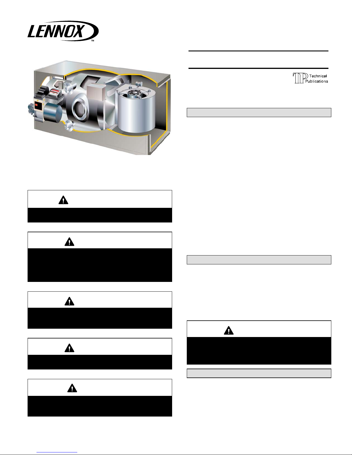
Elite® Series Oil Furnace
These instructions are intended as a general guide and do
not supersede local codes in any way. Only licensed pro
fessional technicians, or equivalent, can install and service
the Lennox Elite® Series ELO183DH oil furnaces. In Cana
da, refer to CSA B139 for recommended installation proce
dures. Consult authorities who have jurisdiction before
installation.
WARNING
Never push the ignition reset button more than one
time. Pushing the reset more than once can lead to
a build-up of oil within the heat exchanger resulting
in a fire or explosion.
Shipping & Packing List
Litho U.S.A.
CAUTION
As with any mechanical equipment, personal injury
can result from contact with sharp sheet metal
edges. Be careful when you handle this equipment.
12/12
*2P1212*
1- Assembled oil furnace
1- Draft control
2- Nozzels
Check the components for shipping damage. If you find
any damage, immediately contact the last carrier.
Page 1
506903-01
*P506903-01*
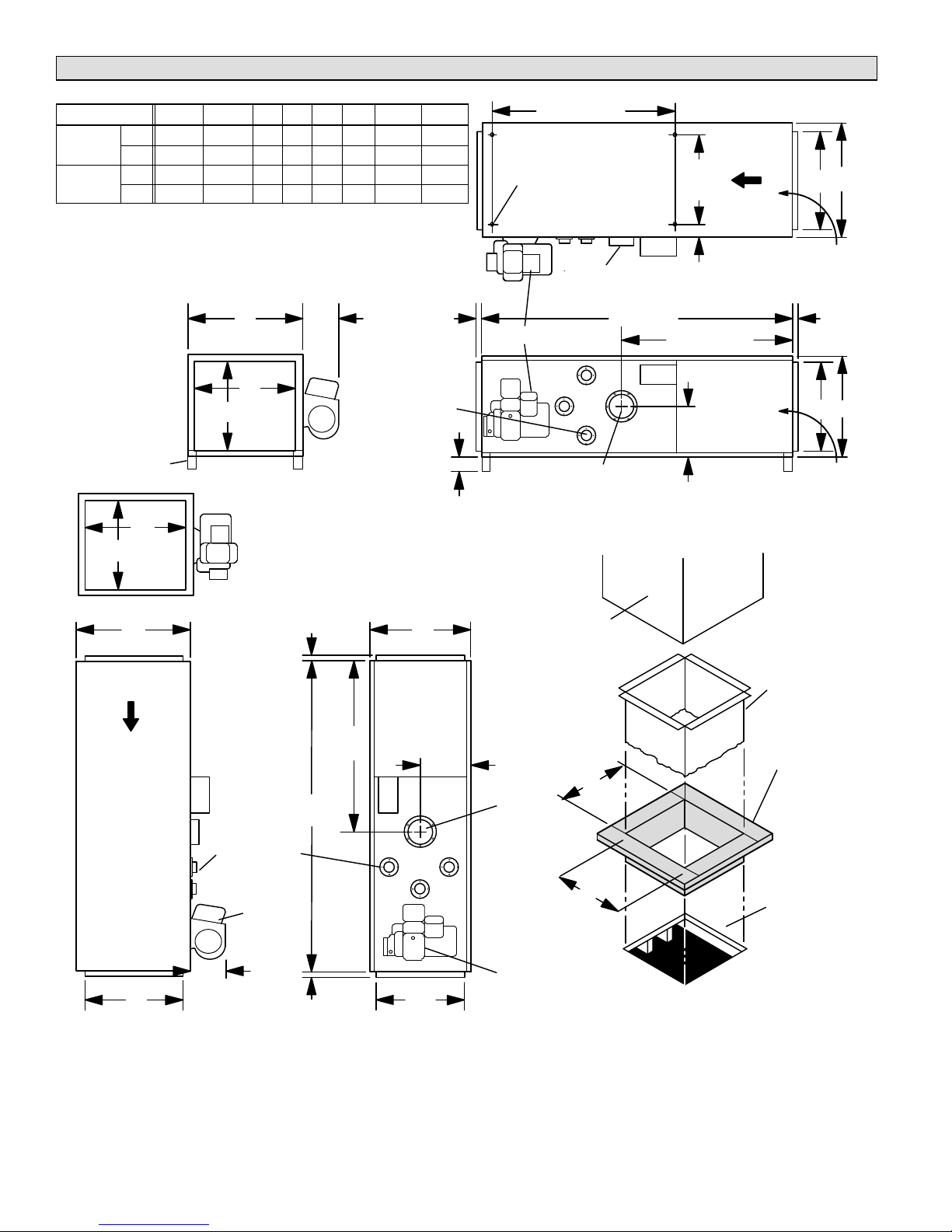
ELO183DH Unit Dimensions - Inches (mm)
Model No. A B C D E F G H
ELO183DH
101/114P36
ELO183DH
135/150P60
in. 20‐1/2 20‐1/2 18 18 18 18 3 10‐1/4
mm 521 521 457 457 457 457 76 260
in. 23‐1/2 23‐1/2 21 21 21 21 4‐3/4 11‐3/8
mm 597 597 533 533 533 533 121 289
53 (1346)
4 KNOCKOUTS
(For Suspending)
TOP VIEW
14‐1/2
3‐1/2
(89)
(368)
AIR
F A
FLOW
(4) SPACER LEGS
F
RETURN
E
AIR
OPENING
TOP VIEW
A
A
8
(203)
C
SUPPLY
D
AIR
OPENING
END VIEW FLUE OUTLET
3/4
(19)
HEAT EX
CHANGER
CLEAN OUT
PORTS (3)
1
(25)
BURNER
HORIZONTAL POSITION
OPTIONAL DOWNFLOW COMBUSTIBLE FLOOR BASE
B
3/4
(19)
FRONT OF
FURNACE
FLUE OUTLET
59 (1499)
G
32‐1/2 (826)
H
SIDE
VIEW
RETURN
AIR
3/4
(19)
E B
RETURN
AIR
SUPPLY
AIR DUCT
(Not
Furnished)
AIR
FLOW
32‐1/2
(826)
59
(1499)
HEAT
EXCHANGER
CLEAN OUT
PORTS (3)
BURNER
3/4
8
(203)
SUPPLY AIR OPENING
(19)
DC
SUPPLY AIR OPENING
SIDE VIEW FRONT VIEW
DOWNFLOW POSITION
101/114—
16‐1/4(413)
H
135/150—
20‐1/4(514)
FLUE
OUTLET
101/114—
16‐1/4(413)
135/150—
20‐1/4(514)
BURNER
Additive Base Raises Furnace
3/4 in. (19 mm) Inch above Floor Level
OPTIONAL
DOWNFLOW
ADDITIVE
BASE
COMBUSTIBLE
FLOOR
Page 2
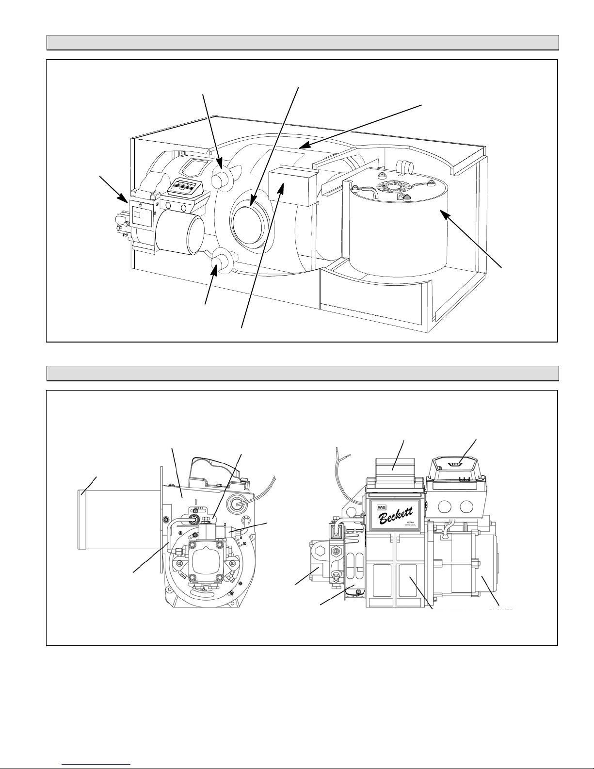
ELO183DH Unit Parts Arrangement
BECKETTR
AFG BURNER
CLEAN-OUT PORT
CLEAN-OUT PORT
FLUE OPENING
HEAT EXCHANGER
INDOOR
BLOWER
CONTROL BOX
Figure 1
ELO183DH Oil Burner Parts Arrangement
MAIN
HEAT
SHIELD
AIR TUBE WITH
ELECTRODE
ASSEMBLY AND
NOZZLE INSIDE
COPPER OIL
TUBE
HOUSING
ESCUTCHEON
PLATE
OIL DELAY
FUEL PUMP
VALVE
AIR BAND AND
AIR SHUTTER
Figure 2
IGNITER
BLOWER WHEEL
WITH AIR GUIDE
(Inside housing)
BURNER CONTROL
(with Reset Button)
BLOWER
MOTOR
Page 3

Requirements
WARNING
Product contains fiberglass wool.
Disturbing the insulation in this product during
installation, maintenance, or repair will expose you
to fiberglass wool dust. Breathing this may cause
lung cancer. (Fiberglass wool is known to the State
of California to cause cancer.)
Fiberglass wool may also cause respiratory, skin,
and eye irritation.
To reduce exposure to this substance or for further
information, consult material safety data sheets
available from address shown below, or contact
your supervisor.
Lennox Industries Inc.
P.O. Box 799900
Dallas, TX 75379-9900
air openings are required. Dimensions of combustion air
openings are shown in table 1. One opening shall be below
burner level and the other opening shall be no more than 6
inches from the room's ceiling.
Combustion air openings should provide a minimum free
area one‐half square inch per 1,000 Btu per hour input.
This combustion air should be brought into the area con
taining the furnace below the level of the furnace burner.
IMPORTANT
An opening to the outside for combustion air is
strongly recommended, especially in new homes.
Refer to table 1 or the unit rating plate for specific
combustion air opening dimensions.
Table 1
Combustion Air Opening Dimensions
Model No. (2 openings required)
WARNING
Improper installation, adjustment, alteration, ser
vice or maintenance can cause property damage,
personal injury or loss of life. Installation and ser
vice must be performed by a qualified installer or
service agency.
Installation of Lennox oil-fired furnaces must conform with
the National Fire Protection Association Standard for the
Installation of Oil Burning Equipment, NFPA No. 31, the
National Electrical Code, ANSI/NFPA No.70 (in the
U.S.A.), CSA Standard CAN/CSA-B139 (in Canada),
Installation Code for Oil Burning Equipment, the Canadian
Electrical Code Part1, CSA 22.1 (Canada), the recom
mendations of the National Environmental Systems Con
tractors Association and any state or provincial laws or lo
cal ordinances. Authorities having jurisdiction should be
consulted before installation. Such applicable regulations
or requirements take precedence over general instruc
tions in this manual.
Chimneys and chimney connectors must be of the type
and construction outlined in section 160 of NFPA No. 31.
Air for combustion and ventilation must conform to stan
dards outlined in section 140 of NFPA No. 31 or, in Cana
da, CSA Standard B139. When installing ELO183DH units
in confined spaces such as utility rooms, two combustion
ELO183DH
-101/114
ELO183DH
-135/150
This unit is approved for clearances to combustible materi
al as listed unit rating plate and in tables 2 or 3. Unit service
and accessibility clearances take precedence over fire
protection clearances.
10” X 20”
11” X 22”
Table 2
Horizontal Installation Clearances
Clearances Inches (mm)
Top of Cabinet 3 (76)
*Bottom and Rear of Cabinet 1 (25)
Front of Cabinet 24 (610)
Service Clearance (Front) 24 (610)
End of Supply Plenum 0 (0)
Supply Air Opening 0 (0)
Return Air Opening 0 (0)
Above Horizontal Warm Air Duct
within 3 ft. (914mm) of Furnace
Flue Pipe Horizontal 7 (178)
Flue Pipe Vertical 7 (178)
*NOTE-When furnace is installed on combustible floor,
1” (25 mm) spacer legs must be installed to elevate unit
off of mounting surface.
0 (0)
Page 4
Table 3
Downflow Installation Clearances
Clearances Inches (mm)
Bottom of Plenum and Ductwork 1 (25)
Plenum Sides 1 (25)
Side of Cabinet 1 (25)
Rear of Cabinet 1 (25)
Front of Cabinet 16 (406)
Service Clearance (Front) 24 (610)
Flue Pipe Horizontal 1 (25)
Flue Pipe Vertical 7 (178)
Return Air Opening 0 (0)
*Floor *Combustible
*NOTE-Clearance for installation on combustible floor if
optional additive base is installed between the furnace
and combustible floor. Not required in add-on coiling ap
plications.
NOTE - Downflow Application Only - For installation on
combustible floors, appliance shall not be installed directly
on carpeting, tile or other combustible material other than
wood flooring. When installed on wood flooring, the addi
tive base must be used. See Unit Dimension illustration.
Combustion & Ventilation Air
Homes built with energy conservation in mind use tight
construction practices. These houses are sealed so well
that it becomes necessary to provide a means of bringing
in air from outside for combustion. Also, exhaust fans, ap
pliance vents, chimneys and fireplaces force additional air
that could be used for combustion out of the house. Unless
outside air is brought into the home for combustion, nega
tive pressure (pressure outside is greater than inside pres
sure) will build to the point that a down draft can occur in the
furnace vent pipe or chimney. Combustion gases enter the
living space creating a potentially dangerous situation. Ne
gative pressure may also interfere with proper combus
tion, causing sooting within the heat exchanger.
The importance of the previous paragraph cannot be over
stated. Users may inadvertently block fresh air intakes af
ter installation.
In the absence of local codes concerning air for combus
tion and ventilation, the following section outlines guide
lines and recommends procedures for operating oil fur
naces in a manner that ensures efficient and safe
operation. Special consideration must be given to com
bustion air needs as well as requirements for exhaust
vents and oil piping.
Combustion Air Requirements
NOTE - Unit must be adjusted to obtain a temperature rise
within the range listed in table 8.
When used in conjunction with a evaporator coil, the fur
nace shall be installed in parallel with, or on the upstream
side of the evaporator coil. In a parallel flow arrangement,
the dampers, or other measures used to control flow of air
flow, shall be adequate to prevent chilled air from entering
the furnace. If the furnace is manually operated, it must be
equipped with means to prevent operation of either unit un
less dampers are in the full‐heat or full‐cool position.
When installed, furnace must be electrically grounded in
accordance with local codes or, in the absence of local
codes, with the current National Electric Code, ANSI/
NFPA No. 70, if an external electrical source is utilized.
Field wiring connection with unit must meet or exceed
specifications of type T wire and withstand a 63_F (17_C)
temperature rise.
Notice to Home Owner
This furnace is equipped with safety devices that protect
you and your property. If one or more of these devices is
activated, furnace operation will stop. If your home is left
unattended for an extended period of time, equipment op
eration must be checked periodically. If this is not possible,
the water supply to the house should be shut off and the
pipes should be drained. This will prevent problems
associated with a NO HEAT condition (frozen pipes, etc.)
CAUTION
Insufficient combustion air can cause headaches,
nausea, dizziness or asphyxiation. It will also cause
excess water in the heat exchanger resulting in rust
ing and premature heat exchanger failure. It can also
cause property damage.
All oil‐fired appliances require air to be used for the com
bustion process. If sufficient amounts of combustion air
are not available, the furnace or other appliance will oper
ate in an inefficient and unsafe manner. Enough air must
be provided to meet the needs of all fuel‐burning ap
pliances, as well as appliances such as exhaust fans which
force air out of the home. When fireplaces, exhaust fans,
or clothes dryers are used at the same time as the furnace,
much more air is required to ensure proper combustion
and to prevent a down‐draft situation. Insufficient amounts
of air also cause incomplete combustion which can result
in sooting. Requirements for providing air for combustion
and ventilation depend largely on whether the furnace is
installed in an unconfined or confined space.
Unconfined Space
An unconfined space is an area such as a basement or
large equipment room with a volume greater than 50 cubic
feet (1.4 cubic meters) per 1,000 Btu (293 W) per hour of
the combined input rating of all appliances installed in that
space. This space also includes adjacent rooms which are
not separated by a door. Though an area may appear to be
unconfined, it might be necessary to bring in outdoor air for
combustion if the structure does not provide enough air by
Page 5
infiltration. If the furnace is located in a building of tight
construction with weather stripping and caulking around
the windows and doors, follow the procedures outlined for
using air from the outside for combustion and ventilation.
Confined Space
A confined space is an area with volume less than 50 cubic
feet (1.4 cubic meters) per 1,000 Btu (293 W) per hour of
the combined input rating of all appliances installed in that
space. This definition includes furnace closets or small
equipment rooms.
When the furnace is installed so that supply ducts carry air
circulated by the furnace to areas outside the space con
taining the furnace, the return air must be handled by ducts
which are sealed to the furnace casing and which termi
nate outside the space containing the furnace. This is es
pecially important when the furnace is mounted on a plat
form in a confined space such as a closet or small
equipment room. Even a small leak around the base of the
unit at the platform or at the return air duct connection can
cause a potentially dangerous negative pressure condi
tion. Air for combustion and ventilation can be brought into
the confined space either from inside the building or from
outside.
Air from an Adjacent Space
If the confined space housing the furnace adjoins space
categorized as unconfined, air can be brought in by provid
ing two permanent openings between the two spaces.
Each opening must have a minimum free area of 1 square
inch (6.4 square centimeters) per 1,000 Btu (293 W) per
hour of the total input rating of all fuel‐fired equipment in the
confined space. Each opening must be at least 100 square
inches (614.5 square centimeters). One opening shall be
within 12” (305 mm) of the top of the enclosure and one
opening within 12” (305 mm) of the bottom (See figure 1).
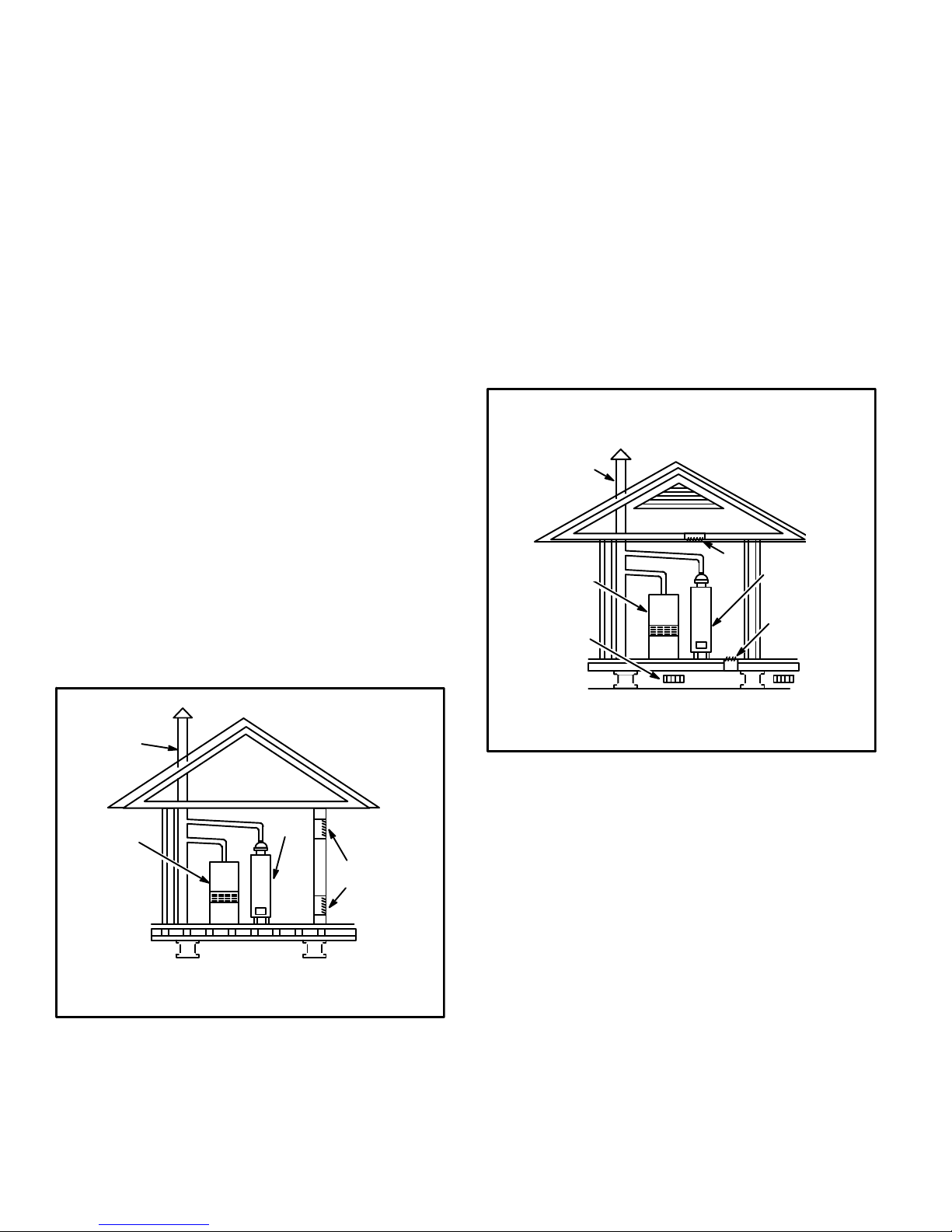
Equipment In Confined Space
All Air From Inside
Chimney or
t
Oil Ven
Air from Outside
If air from outside is brought in for combustion and ventila
tion, the confined space shall be provided with two perma
nent openings. One opening shall be within 12” (305 mm)
of the top of the enclosure and one within 12” (305 mm) of
the bottom. These openings must communicate directly or
by ducts with the outdoors or spaces (crawl or attic) that
freely communicate with the outdoors or indirectly through
vertical ducts. Each opening shall have a minimum free
area of 1 square inch (6.4 square centimeters) per 4,000
Btu (1172 W) per hour of total input rating of all equipment
in the enclosure. (See figure 2.) When communicating with
the outdoors through horizontal ducts, each opening shall
have a minimum free area of 1 square inch (6.4 square
centimeters) per 2,000 Btu (586 W) per total input rating of
all equipment in the enclosure (See figure 3).
Equipment In Confined Space
(Inlet Air from Crawl Space and Outlet Air to
Chimney or
Oil Vent
Oil
Furnace
Ventilation
Louvers
(For unheated
crawl space)
NOTE-The inlet and outlet air openings shall each have a free area of
at least one square inch (6.4 square centimeters) per 4,000 Btu (1172
W) per hour of the total input rating of all equipment in the enclosure.
All Air From Outside
Ventilated Attic)
Ventilation Louvers
(Each End Of Attic)
Outlet
r
Ai
Water
Heater
Inlet
Air
Figure 2
Oil
Furnace
NOTE-Each opening shall have a free area of at least 1 square inch
(6.4 square centimeters) per 1,000 Btu (293 W) per hour of the total
input rating of all equipment in the enclosure, but not less than 100
square inches (614.5 square centimeters).
Water
Heater
Figure 1
Openings
(To Adjacent Room)
When ducts are used, they shall be of the same cross-sec
tional area as the free area of the openings to which they
connect. The minimum dimension of rectangular air ducts
shall be no less than 3” (76 mm). In calculating free area,
the blocking effect of louvers, grilles, or screens must be
considered. If the design and free area of protective cover
ing is not known for calculating the size opening required, it
may be assumed that wood louvers will have 20 to 25 per
cent free area and metal louvers and grilles will have 60 to
75 percent free area. Louvers and grilles must be fixed in
the open position or interlocked with the equipment so that
they are opened automatically during equipment opera
tion.
Page 6
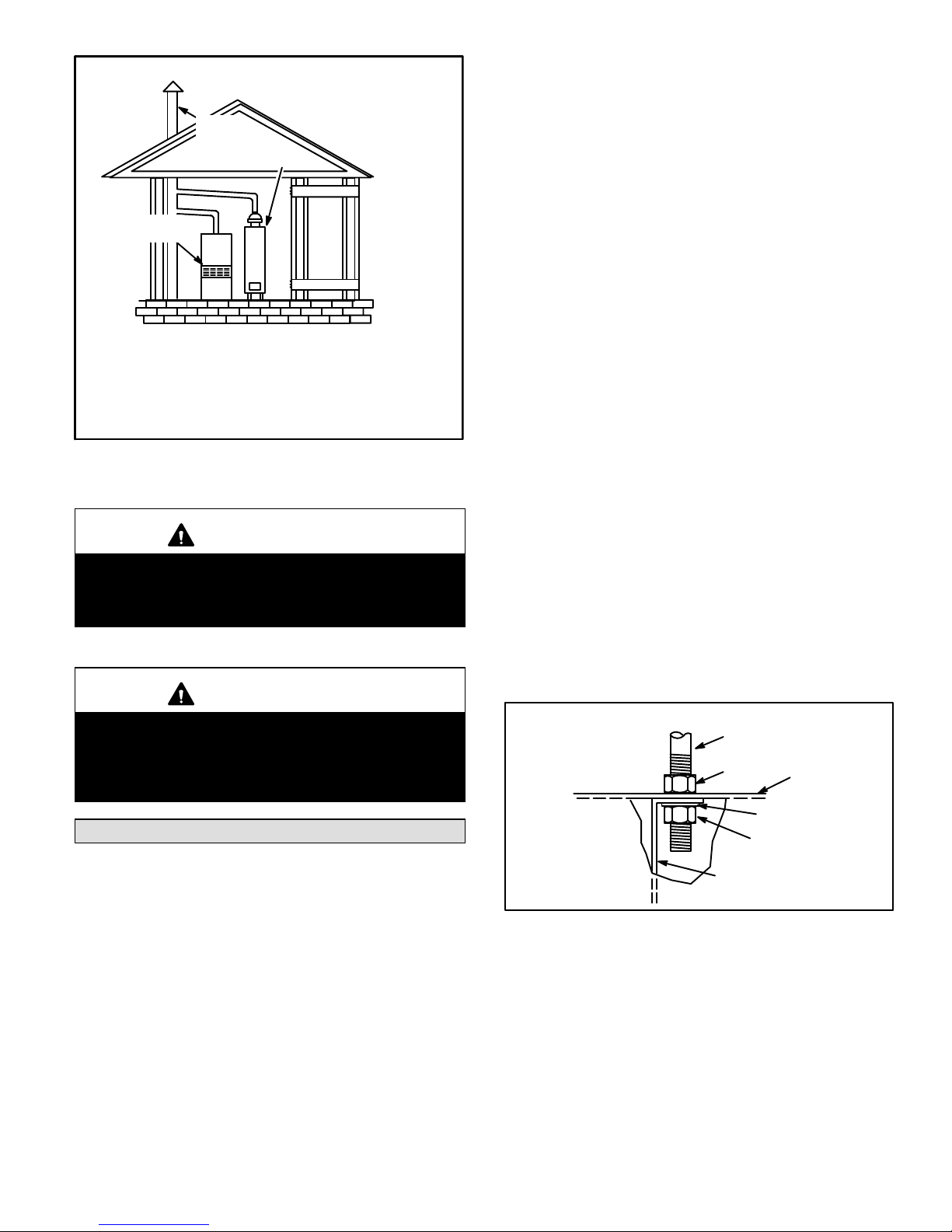
Equipment In Confined Space
All Air From Outside
Chimney
Or Oil
Vent
Oil
Furnace
NOTE-Each air duct opening shall have a free area of at least one
square inch (6.4 square centimeters) per 2,000 Btu (586 W) per hour
of the total input rating of all equipment in the enclosure. If the equip
ment room is located against an outside wall and the air openings
communicate directly with the outdoors, each opening shall have a
free area of at least one square inch (6.4 square centimeters) per
4,000 Btu (1172 W) per hour of the total input rating of all other equip
ment in the enclosure.
Water
Heate
r
Outlet Air
Inlet Air
Figure 3
CAUTION
Combustion air openings in the front of the furnace
must be kept free of obstructions. Any obstruction
will cause improper burner operation and may re
sult in a fire hazard or injury.
CAUTION
The barometric draft control shall be in the same at
mospheric pressure zone as the combustion air in
let to the furnace. Deviation from this practice will
cause improper burner operation and may result in
a fire hazard or injury.
Horizontal Application
The ELO183DH furnace is shipped from the factory in the
horizontal left hand air discharge application. Air flow may
be reversed to right side discharge or unit may be used as
downflow.
1. Reversing Airflow for Right Hand Discharge
D Rotate the furnace 180_ so that, when facing the
front, the warm discharge is to the right.
D Remove the nuts in the bracket that hold the burn
er to the furnace front. Rotate the burner and burn
er mounting plate 180_ and reinstall the nuts.
D Remove the screws that hold the limit control in
place. Use the provided knockout hole to relocate
the limit control to the top side of the front panel.
2. Installation on Non-Combustible Material
D Set the furnace on non‐combustible material
(such as concrete blocks, bricks or angle iron).
Install spacer legs, provided with unit, by using the
cabinet screws from each corner of the unit.
D Use a level to check the level of furnace in at least
two directions. Use shims or non‐combustible ma
terial. A minimum clearance of 1” must be main
tained between bottom of furnace and combus
tible material.
3. Suspended Installation
D To suspend the furnace, remove knockouts in top
of panel at warm air discharge and at blower panel
(Refer to unit dimensions). Use 3/8” rods cut to de
sired length.
D Use one flat washer and two nuts for each rod (a
nut and washer on the inside of unit and the other
“locking” nut on the outside of unit; see figure 4).
Level the unit by adjusting the nuts on the inside of
unit.
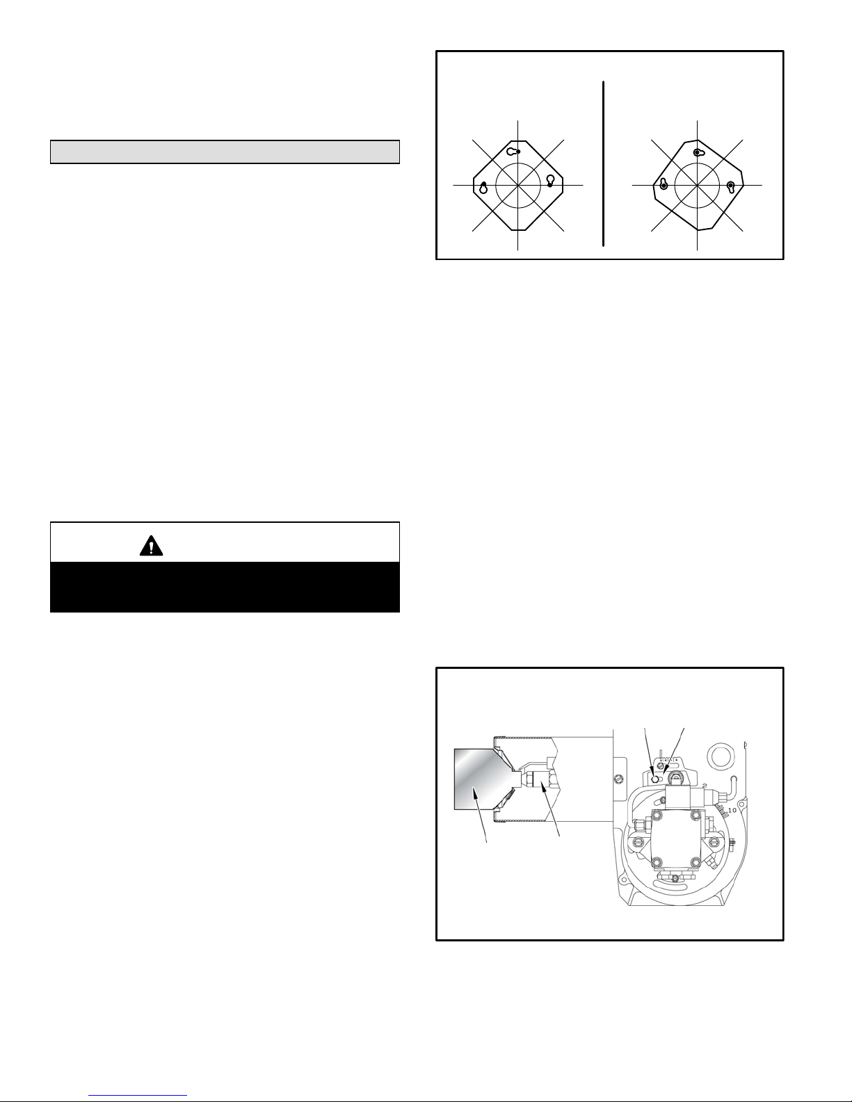
Hanger Rod Installation
ROD
LOCKING
NUT
TOP OF
FURNACE
Installation
When installed, ELO183DH furnaces must be level. If the
furnace is not level, place fireproof wedges or shims be
tween the low side of the furnace and floor. Make sure the
weight of the furnace is evenly distributed on all four cor
ners. Strain on sides of the cabinet causing cracking and
popping noises may occur if weight of furnace is not evenly
distributed.
Set the unit in desired location keeping in mind the clear
ances list in tables 2 and 3. Also keep in mind oil supply
connections, electrical supply, flue connections and suffi
cient clearance for installing and servicing unit.
ELO183DH series units may be installed in a crawl space
under a house, utility room or in a wide variety of sus
pended applications.
WASHER
NUT
BLOWER COMPARTMENT
DIVISION PANEL
Figure 4
Downflow Application
When installing the ELO183DH in a downflow position and
on combustible flooring, a combustible floor base must be
used. See Unit Dimension illustration.
1. Rotate the furnace so that return is on top and supply
is on bottom. Refer to table 3 for clearances to com
bustible flooring.
2. Remove the nuts in the bracket that hold the burner to
the furnace front. Rotate the burner and burner mount
ing plate 90_ and reinstall the nuts.
Page 7
3. It is also recommended that the upper rear screw hold
ing the blower housing to the blower deck be removed
before installation in a closet. Removing this screw al
lows for easy service and removal of the blower as
sembly in a closet installation.
Adjustments
Neither the nozzle setting nor the air adjustments are fac
tory set. The furnace is fire-tested and the limit control is
checked to make sure it functions properly; no factory set
tings are made. During installation, the furnace must be
adjusted to ensure proper operation. The installing dealer/
contractor must have and use proper test equipment in or
der to correctly adjust the oil furnace. The use of test equip
ment is more critical than ever due to tighter tolerances
needed to keep the furnace operating efficiently.
Among the test equipment for an oil furnace, the proper
combustion test kit should contain the following:
D Draft gauge
D CO
or O2 analyzer
2
D Smoke tester
D Pressure gauge
D High temperature thermometer
D Oil vacuum gauge
D Beckett T-501 or Z-2000 nozzle gauge
D Knowledge of proper test equipment operation
CAUTION
Improper nozzle and/or air adjustment of this unit
may result in sooting problems. Refer to the follow
ing section for correct adjustment procedures.
Nozzle Adjustment
Proper adjustment of the nozzle assembly is critical. Be
fore the flue pipe and oil lines are installed, the nozzle as
sembly must be checked for proper depth and alignment.
You must remove the entire burner assembly (not just the
nozzle) from the furnace to check the nozzle depth and
alignment. The smaller sized firing nozzle has been facto
ry-installed. This should be verified by the installer. A larger
nozzle has been provided in the bag assembly for use with
ELO183DH114 and 150 units. Inspect the spark trans
former leads also to ensure they are still attached to the
electrodes.
The burner assembly is attached to the vestibule panel by
three nuts. Slots are provided in the mounting flange for re
moving the burner assembly from the vestibule. Loosen
the nuts and turn the whole burner assembly clockwise
(figure 5) to remove the entire burner assembly from the
furnace. There is adequate wire to remove the burner with
out disconnecting wires. Once removed, turn the burner
around in the vest panel area.
ELO183DH Series Burner Removal
First, loosen three nuts which
attach burner to vest panel.
Next, rotate burner clockwise
on slots then pull toward you.
Figure 5
To correctly check and adjust the nozzle depth and align
ment, use the Beckett T-501 or Z-2000 gauge.
To check the oil nozzle depth, insert the small end of the
gauge into the end of the cone and measure from the flat of
the end cone to the face of the nozzle. When nozzle depth
is correct, the tip of the nozzle should just touch the end of
the gauge. Refer to the illustration sheet provided with the
gauge. Note that the scale side of the gauge is not used for
this purpose. If necessary, loosen the escutcheon plate
securing screw and slide the entire nozzle assembly for
ward or backward within the air tube (figure 6). Re-secure
escutcheon plate screw when adjustment is completed.
To check nozzle alignment, again insert the small end of
gauge into the end cone and measure the nozzle and elec
trode alignment against the center lines marked on the
gauge (again refer to enclosed illustration sheet). If the
nozzle is not centered, but found to be too far left or right, a
new nozzle assembly will need to be ordered. Do not at
tempt to adjust by bending the 90 degree elbow in the oil
line.
Take care to properly re-install burner assembly when
nozzle adjustment has been completed.
Beckett Oil Burner Nozzle Adjustment
Burner must be removed from
furnace for this procedure.
T-501 Gauge
To Adjust Nozzle
1-Loosen escutcheon plate screw.
2-Slide entire nozzle/electrode assembly back and forth inside air
tube until nozzle just touches gauge.
2
1
Escutcheon Plate
Figure 6
Page 8
 Loading...