

Lennox Elite CB30U, Elite CB30U-21, Elite CB30U-26, Elite CB30U-31, Elite CB30U-41 Installation Instructions Manual
...Page 1
zav
,B,2007 Lennox IndustrIes Ins.
Da{las, Texas, USA
INSTALLATION
INSTRUCTIONS
X_ WARNING
_, CAUTION
IMPORTANT
_, IMPORTANT
Elite® Series CB30U Units
AIR HANDLER F[_ Technical
505,340M J_LL Publications
07/07 Litho U.S.A.
Supersedes 504,720M
CB30U Up-flow Unit Dimensions ................ 2
CB30U Up-flow Side Return Air Filter Adapter ..... 2
General Information ............................ 3
Shipping and Packing List ...................... 3
Requirements ................................. 3
Installing the Unit .............................. 3
Brazing Connections ........................... 4
Installing the Condensate Drain .................. 5
Inspecting and Replacing Filters ................. 5
Sealing the Unit ............................... 6
Adjusting the Blower Speed .................... 6
Making Electrical Connections ................... 8
Repairing or Replacing Cabinet Insulation ......... 12
RETAIN THESE INSTRUCTIONS FOR FUTURE REFERENCE
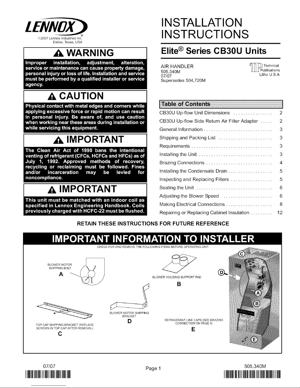
BLOWER MOTOR
SHIPPING BOLT
TOP CAP SHIPPING BRACKET (REPLACE
SCREWS IN TOP CAP AFTER REMOVAL)
C
CHECK FOR AND REMOVE THE FOLLOWING ITEMS BEFORE OPERATING UNIT.
BLOWER HOUSING SUPPORT PAD
B
BLOWER MOTOR SHIPPING
BRACKET
D
REFRIGERANT LINE CAPS [SEE BRAZING
CONNECTION ON PAGE 4]
E
@..
07/07
IIIHIIIIIIIIIIIIIIIIIIIIIIIIIIIIIIIII
Page1
505,340M
IIIIIIIIIIIIIIIIIIIIIIIIIIIIIIIIIIIIIIIIIIIIIIIIII
Page 2
3/4
t(19)
3/4 3/4
(19)_ _1_)
DETAIL OF PIPING PLATE
t 5/8
OPTIONAL
ELECTRIC
HEAT
(Field
InstaBed)
FILTER
ACCESS
A
LIQUID
LINE
SUCTION
LINE
K
SIDE VIEW
LINE VOLTAGE LOW VOLTAGE
INLETS INLETS
(Top and Left Side) (Top and
TOP VIEW
Right Side)
I
I
JL__J JL_
5/8 F (215) BottEom
Bottom 5/8
Return Air (16)
(16) Return Air
FRONTVIEW
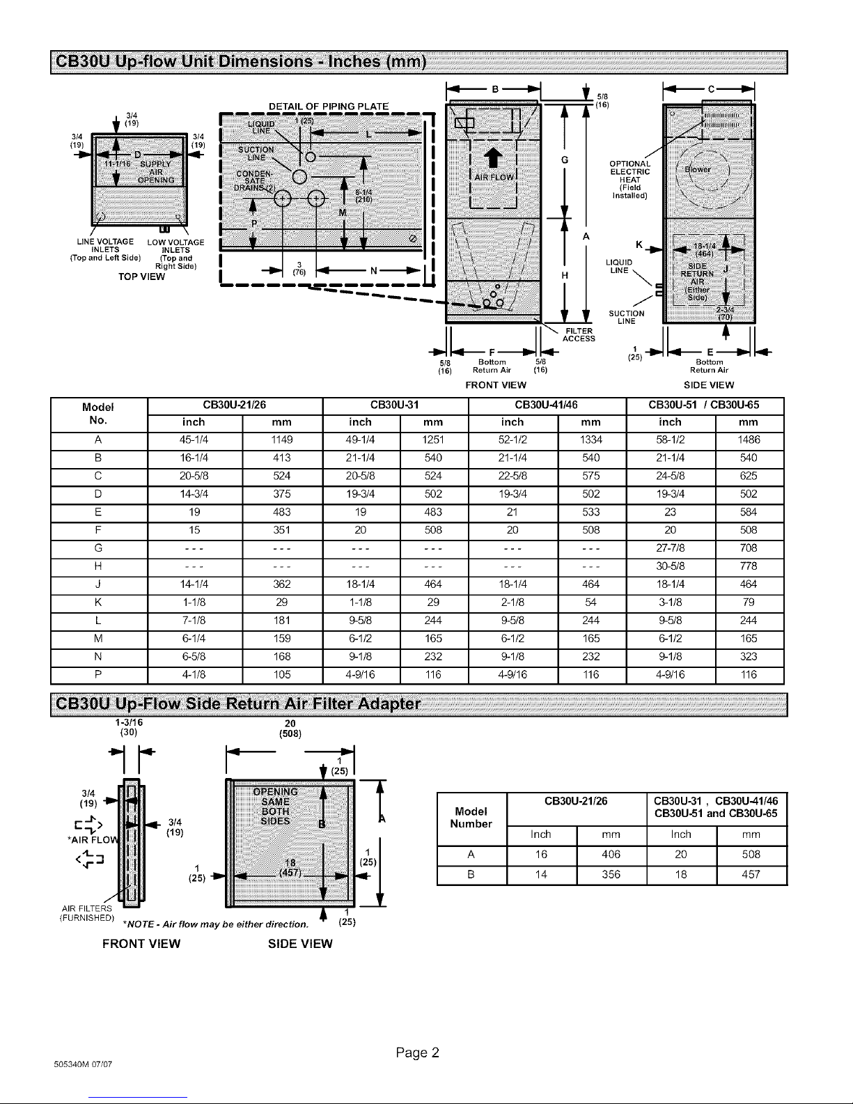
Model CB30U-21/26 CB30U-31 CB30U-51 / CB30U-65
No. inch mm inch mm mm inch mm
A 45-1/4 1149 49-1/4 1251 1334 58-1/2 1486
B 16-1/4 413 21-1/4 540 540 21-1/4 540
C 20-5/8 524 20-5/8 524 575 24-5/8 625
D 14-3/4 375 19-3/4 502 502 19-3/4 502
E 19 483 19 483 533 23 584
F 15 351 20 508 508 20 508
CB30U-41/46
inch
52-1/2
21-1/4
22-5/8
19-3/4
21
2O
G ............... 27-7/8 708
H ............... 30-5/8 778
J 14-1/4 362 18-1/4 464 464 18-1/4 464
K 1-1/8 29 1-1/8 29 54 3-1/8 79
L 7-1/8 181 9-5/8 244 244 9-5/8 244
M 6-1/4 159 6-1/2 165 165 6-1/2 165
N 6-5/8 168 9-1/8 232 232 9-1/8 323
P 4-1/8 105 4-9/16 116 116 4-9/16 116
18-1/4
2-1/8
9-5/8
6-1/2
9-1/8
4-9/16
(19)
3/4
1-3/16
(30)
ii _:_NiN;i!N_;i!iiiili;iiii!ilililililill|!:!:!:;!i!i!_!:!i!ili!iiii_i!!
i
i _iiiiiiiiiiiii'i;!ii_!;i;i
20
(508)
3,, i ii ii ii ii ii ii ii ii iiiiii!;!ii!;'ii]i
(,9, iiiiiiiiiiii i ;! :!: i i i;!i !: ! i i ii i : i ii iiiii i i i iiii iiii iiiiiiiiiiiiiiiiiiiiii!!!!!! iiiiiiiiiiiiiiiiiiiiiiiiiiiiiiiiiiiiiiiiiiiiiii!ii!ii!iiiiiiii"':ii!i!i!!i!iiiiiiiiiiiiiiiii!i!iiiiiiiiiiii!!ii!i!ii'iiil
(25) '_
1 ii_I:I:I:I:_!_!_!_!_!_!_!:_i_!i_i_i_i!i_i_:iiiiiiiiiiiiiiiiiiiiiiiiiiiiiiiiiiiiiiii:!_:_iii:iI_;!!_!I;_i_i ii_iiiii!iiiiiiiiiii!!i_ii
AIR FILTERS
(FURNISHED)
505340M 07/07
*NOTE - Air flow may be either direction.
FRONT VIEW SIDE VIEW
I_ (25)
Page 2
Model CB30U-51 and CB30U-65
CB30U-21/26 CB3OU-31 , CB30U-41/46
Number
Inch mm Inch mm
A 16 406 20 508
B 14 356 18 457
Page 3
WARNING
The CB30U series air handler units are designed for
installation with optional field-installed electric heat and a
matched remote outdoor unit. These units are for indoor
installation only. The CB30U units are designed for up-flow
operations with either bottom or side return air
applications.
These instructions are intended as a general guide and do
not supersede local or national codes in any way. Consult
authorities having jurisdiction before installation. Check
equipment for shipping damage; if found, immediately
report damage to the last carrier.
Package 1 of 1 contains the following:
1--Assembled air handlerunit
In addition to conforming to manufacturer's installation
instructions and local municipal building codes, installation
of Lennox air handler units (with or without optional electric
heat), MUST conform with the following National Fire
Protection Association (NFPA) standards:
• NFPA No. 90A - Standard for Installation of Air
Conditioning and Ventilation Systems
• NFPA No. 90B - Standard for Installation of Residence
Type Warm Air Heating and Air Conditioning Systems
This unit is approved for installation clearances to
combustible materials as listed on the unit rating plate which
is located on the unit. Accessibility and service clearances
must take precedence over combustible material
clearances.
I
CB30U units come from the factory ready for up-flow,
bottom return installation. This unit is not designed for
down-flow or horizontal discharge. Return air for the
CB30U may be either from the bottom or sides of the unit.
Side return air applications require some field
modifications.
WARNING
IMPORTANT
DISASSEMBLE/REASSEMBLE AIR HANDLER UNITS
The air handler units consists of two factory-assembled
sections. It may be necessary to disassemble the sections
when positioning the unit for installation,
To disassemble:
Step 1. Remove access panels,
Step 2, Remove both blower and coil assemblies, This
will lighten the cabinet for lifting,
Step 3, Remove one screw from the left and right posts
To reassemble:
Step 1. Align cabinet sections together.
Step 2, Reinstall screws,
Step 3, Replace blower and coil assemblies,
Step 4, Replace access panel,
UP-FLOW APPLICATION
Use the following procedures to configure the unit for
up-flow operations:
Step 1, Remove access panels and corrugated padding
Step 2. Place unit in desired location. Set unit so that it
Step 3, Mount units that have no return air plenum on a
Table 1. Optional Unit Side Stand (Up-Flow Only)
Model Kit Number
-21, -26, and -31 45K31
41 through-65 45K32
inside the unit, Remove one screw from each
side on the back of the unit, Unit sections will now
separate,
between the blower and coil assembly before
operation,
is level. Connect return and supply air plenums
as required using sheet metal screws.
stand at least 14" from the floor for proper air
return, Lennox offers an optional up-flow unit
stand as listed in table 1.
Page 3
CB30U/CBX27UH SERIES
Page 4
SIDE RETURN AIR APPLICATIONS
The CB30U unit is shipped from the factory ready for
bottom return air application. You can order an optional
side return air filter kit as listed in table 2.
Table 2. Optional Side Return Air Filter Kit
Model Kit Number
-21 and-26 65K23
All other models 65K24
Use the following procedures to configure the unit for side
return air operations:
All CB30U coils are equipped with a factory-installed,
internally mounted expansion valve. Use Lennox L15
(sweat) series line sets as shown in table 2 or use
field-fabricated refrigerant lines, L10 (flare) line sets may
be used by cutting off flare nut. Refer to the piping section
of the Lennox Unit Information Service Manual for proper
size, type, and application of field-fabricated lines.
_WARNING
Step 1,
Step 2,
Step 3.
Step 4.
Step 5.
Remove the coil access panel,
Remove the coil assembly from the cabinet,
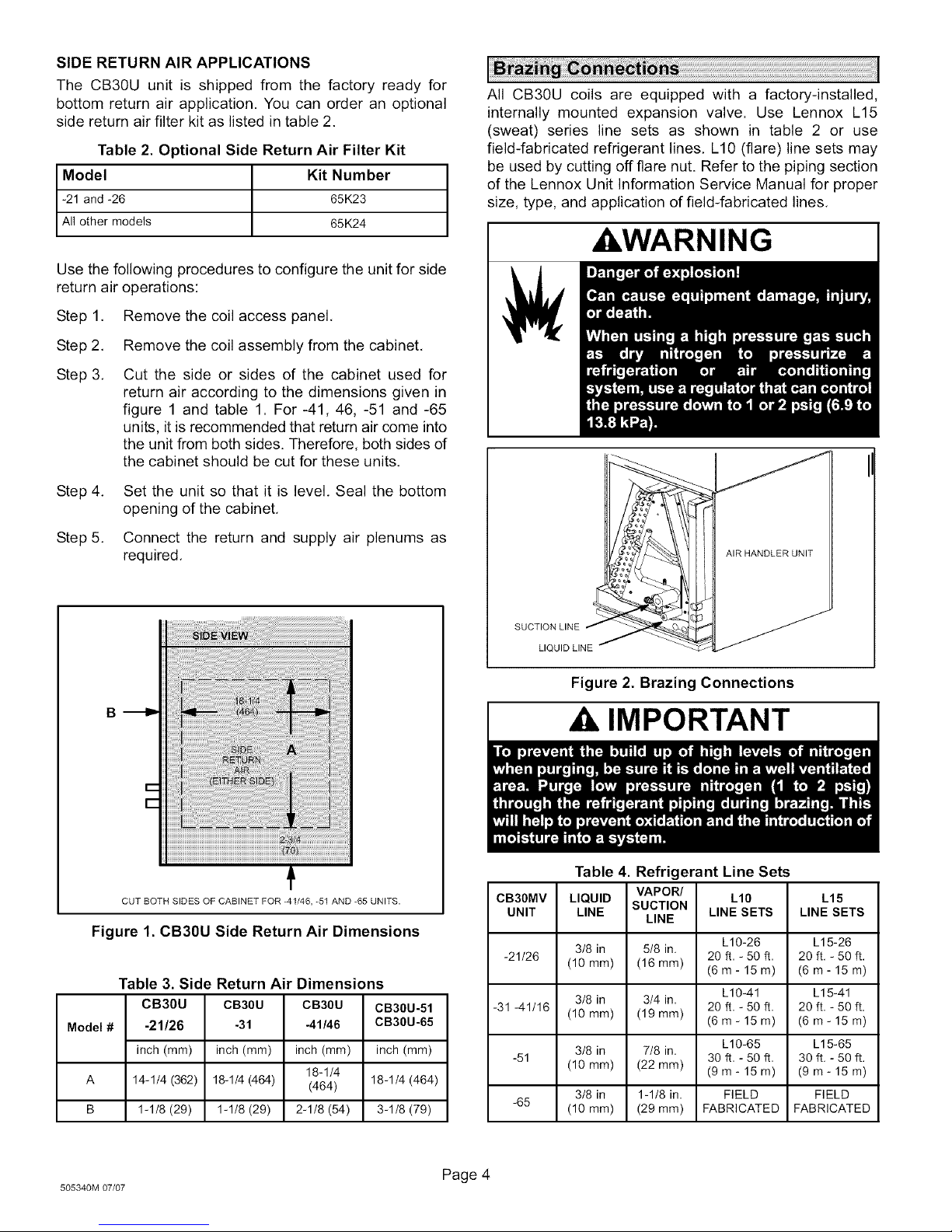
Cut the side or sides of the cabinet used for
return air according to the dimensions given in
figure 1 and table 1. For -41, 46, -51 and -65
units, it is recommended that return air come into
the unit from both sides. Therefore, both sides of
the cabinet should be cut for these units,
Set the unit so that it is level. Seal the bottom
opening of the cabinet,
Connect the return and supply air plenums as
required.
B
I AIR HANDLER UNIT
SUCTION LINE
LIQUID LINE
Figure 2. Brazing Connections
Ak IMPORTANT
CUT BOTH SIDES OF CABINET FOR -41/46, -51 AND -65 UNITS.
Figure 1. CB3OU Side Return Air Dimensions
Table 3. Side Return Air Dimensions
CB3OU CB30U CB30U CB30U-51
Model # -21/26 -31 -41/46 CB30U-65
inch (mm) inch (mm) inch (mm) inch (mm)
18-1/4
A 14-1/4 (362) 18-1/4 (464) (464) 18-1/4 (464)
B 1-1/8 (29) 1-1/8 (29) 2-1/8 (54) 3-1/8 (79)
505340M 07/07
Page 4
Table 4. Refrigerant Line Sets
CB30MV LIQUID SUCTION L10 L15
UNIT LINE LINE SETS LINE SETS
-21/26 (10 mm) (16 mm) 20 ft, - 50 ft, 20 ft. - 50 ft.
-31 -41/16 (10 mm) (19 mm) 20 ft, - 50 ft. 20 ft. - 50 ft.
-51 30 if, - 50 ft, 30 ft. - 50 ft.
-65 (10 ram) (29 ram) FABRICATED FABRICATED
3/8 in 5/8 in.
3/8 in 3/4 in,
3/8 in 7/8 in.
(10 mm) (22 mm) (9 m - 15 m) (9 m- 15 m)
3/8 in 1-1/8 in, FIELD FIELD
VAPOR/
LINE
L10-26 L15-26
(6m- 15m) (6m-15m)
L10-41 L15-41
(6 m - 15 m) (6 m- 15 m)
L10-65 L15-65
Page 5

NOTE - CB3OMV series evaporators use nitrogen or dryair
as aholding charge. If there is no pressure when the rubber
plugs are removed, check the coil or line set for leaks before
installing. After installation, pull a vacuum on theline set and
coil before releasing the unit charge into the system.
NOTE: See outdoor unit instructions on how to flow
nitrogen through line sets.
Step 1. Remove access panel,
Step 2, Remove the refrigerant line caps from the
refrigerant lines,
Step 3, Use a wet rag to protect TXV sensing bulb (or
remove it) when brazing suction line
connections,
Step 4, Place a wet rag against piping plate and around
the suction line connection. The wet rag must be
in place to guard against damage to the paint.
Step 5, With the wet rag in place, position field provided
elbow fitting to air handler's suction line and line
set, Start nitrogen flow before brazing.
Step 6, After the procedure is completed then remove
the wet rag,
Step 7, Place wet rag against piping plate and around
the liquid line connection. Position liquid line
elbow to air handler's suction line and to line set.
Start nitrogen flow and begin brazing both
connections and after procedure is completed
then remove both wet rags,
Step 8, Refer to instructions provided with outdoor unit for
leak testing, evacuating and charging
procedures,
Step 9. Install access panel,
Connect the main condensate drain and route it downward
to an open drain or sump. Do not connect the drain to a
closed waste system. Refer to figure 3 for a typical
condensate trap configuration. If the auxiliary drain is not
connected, it must be plugged,
MINIMUM 1 INCH (25 MM) PIPE DIAMETER
PITCH PER 10 FEET (3048 MM)
TRAP MUST BE DEEP ENOUGH TO OFFSET MAXIMUM STATIC
DIFFERENCE (GENERALLY, 2 INCHES [51 MM] MINIMUM).
OF LINE _. DIFFERENCE
_t .... CO,L
RAIN PAN
Figure 3. Typical Condensate Drain
The following practices are recommended to ensure
condensate removal:
• The drain piping should not be smaller than the drain
connections at drain pan,
• A trap must be installed in the main drain line,
• The trap must be deep enough to offset the difference
in static pressure between drain pan and atmosphere.
Generally, two inches is satisfactory for medium static
applications.
• Horizontal runs must be sloped 1 inch per 10 feet of
drain line to offset friction,
• An open vent inthe drain line will sometimes be required
due to line length, friction, and static pressure,
• Drains should be constructed in a manner to facilitate
future cleaning and should not interfere with filter
access as illustrated in figure 3,
• Auxiliary drain should run to an area where the
homeowner will notice it draining, Refer to local codes,
A IMPORTANT
You can duct mount or install filters in the cabinet, The unit
is not equipped with a filter from the factory. Note that the
filter access door fits over the access panel. Air leaks will
occur if the access panel is placed over the filter door.
Filters should be inspected monthly and must be cleaned
or replaced when they dirty to assure proper furnace
operation,
Reusable filters can be washed with water and mild
detergent, When dry, they should be sprayed with filter
handicoater prior to reinstallation. Filter handicoater is RP
Products coating #418 and is available as Lennox part
number P-8-5069. Replace throw-away type filters when
they are dirty; they cannot be cleaned.
The filter section built into the unit may be used with bottom
return air applications,
To replace filter:
Step 1, Loosen the thumbscrews holding the filter panel
in place.
Step 2. Slide the filter out of the guides on either side of
cabinet,
Step 3, Insert new filter.
Step 4, Replace panel.
See table 5 for replacement filter sizes.
Table 5. Filter Dimensi, >ns
UNIT MODEL
NO.
CB30U-21/26 15 x 20 (381 x508) 16 x 20 (406 x 508)
CB30U-31 20 x 20 (508 x 508) 20 x 20 (508 x 508)
CB30U-41/46 20 x 22 (508 x 559) 20 x 20 (508 x 508)
CB30U-51,-65 20 x 24 (508 x 610) 20 x 20 (508 x 508)
BOTTOM RETURN SIDE RETURN
FILTER SIZE FILTER SIZE
Inches (mm) Inches (mm)
Page 5
CB30U/CBX27UH SERIES
Page 6

Seal the unit so that warm air is not allowed into the
cabinet. Warm air introduces moisture, which results in
water blow-off problems. This is especially important when
the unit is installed in an unconditioned area.
Make sure the liquid line and suction line entry points are
sealed with either the provided flexible elastomeric thermal
insulation, or field provided material (e.g. Armaflex,
Permagum or equivalent). Any of the previously mention
materials may be used to seal around the main and
auxiliary drains, and around open areas of electrical inlets.
AIR VOLUME ADJUSTMENT
Select the Blower speed by changing the taps at the
harness connector at the blower motor as illustrated in
figure 4. For selecting the blower speed and see figure 9 on
page 11 for the unit wiring diagram. Refer to the tables 6
through 10 for blower performance data.
HARNESS
CONNECTOR
MINIMUM BLOWER SPEEDS (WITH ELECTRIC
HEATERS)
Press the tab to release
wire connector, select
connector location for
For the minimum allowable speed for the CB30U series newspeed.Insert wire
units with electric heat, refer to the ECB29/ECB31 untilit clicks.
installation instructions.
Figure 4. Blower Speed Tap Selection
Table 6. CB30U-21/26 Air Handler Performance (208/230v)
External Static Air Volume and Motor Watts at Specific Blower
in. w.g.
.00
.05
.10
.15
,20
.25
.30
.40
.50
.60
.70
.75
Pressure
Pa
o
lO
25
35
50
6o
75
lOO
125
15o
175
185
cfm
1035
1020
1005
985
965
940
920
865
8O5
735
655
615
High
L/s
49O
48O
475
465
455
445
435
410
380
345
310
29O
Watts
390
385
380
375
370
365
360
345
330
320
3o5
295
cfm
85O
840
830
820
8O5
790
770
725
670
610
535
5OO
NOTE - All air data is measured external to the unit with air filter in place
Medium
L/s
4OO
395
395
385
380
37O
365
340
315
285
255
235
bottom return air or side return
with
Watts
3o5
3oo
295
29o
285
28o
275
265
25o
24o
225
215
Taps
Low
cfm L/s Watts
670 315 230
665 315 230
660 310 225
650 305 225
640 300 220
625 295 220
610 290 215
575 270 210
535 250 200
485 230 190
430 200 180
395 190 175
a_ (with bothsides
open). Electric heaters have no appreciable air resistance.
Table 7. CB30U-31 Air Handler Performance (208/230v)
External Static Air Volume and Motor Watts at Specific Blower
in. w.g.
.00
.05
.10
.15
.20
.25
.30
.40
.50
.60
.70
.75
Pressure
Pa
o
lO
25
35
5o
6o
75
lOO
125
15o
175
185
cfm
1255
1245
1230
1205
1170
1125
1065
925
740
520
255
110
High
L/s
59O
59O
58O
57O
55O
53O
5O5
435
350
245
120
5O
Watts
35o
35o
345
340
330
320
315
295
28o
26o
240
23o
cfm L/s
1190 560
1190 560
1175 555
1155 545
1120 530
1080 510
1030 485
895 425
725 340
510 240
260 120
115 55
NOTE - For side return air applications (with both sides open) add:. 10 in. wc. (25 Pa) static capacity to unit performance. Electric heaters
have no appreciable air resistance. Aft air data is measured external to the unit with the air filter in place with bottom return air.
Medium
Watts
315
315
31o
300
290
285
275
255
240
220
2o0
19o
Taps
Low
cfm L/s Watts
1045 495 265
1050 495 265
1040 490 255
1025 485 250
1005 475 245
970 460 235
930 440 225
820 385 205
670 315 185
490 230 165
275 130 145
150 70 135
505340M 07/07
Page 6
Page 7

Table 8. CB3OU-41/46 Air Handler Performance (208/230v)
External Static
Pressure
in. w.g.
.00
.05
.10
.15
.20
.25
.30
.40
.50
.60
.70
.75
Pa
o
lO
25
35
5o
6o
75
lOO
125
15o
175
185
NOTE -For side return a_ applications (with both sides open) add:. 15 in. w._ (35 Pa) static capacity to un# performance. Electric heaters
have no appredable a_ resistance. Aft a_ data _ measured external to the un# with the a_ filter in place with boffom return a_
External Static Air Volume and Motor Watts at Specific Blower Taps
Pressure High Medium Low
in.w.g. Pa cfm L/s Watts cfm L/s Watts cfm L/s Watts
.00 0 1805 855 600 1615 765 525 1355 640 445
.05 10 1780 840 585 1605 755 515 1355 640 445
.10 25 1745 825 570 1585 750 505 1355 640 440
.15 35 1710 805 560 1560 735 490 1350 635 425
.20 50 1670 790 545 1535 725 480 1335 630 415
.25 60 1625 765 530 1500 710 465 1320 620 400
.30 75 1575 745 515 1465 690 450 1295 610 390
.40 100 1470 695 485 1375 650 420 1230 580 360
.50 125 1350 635 460 1265 595 395 1145 540 335
.60 150 1215 570 430 1140 535 365 1035 490 310
.70 175 1060 500 400 990 470 335 905 425 285
.75 185 980 460 385 910 430 320 830 390 270
NOTE -For side return a_ applications (with both sides open) add:. 15 in. w._ (35 Pa) static capacity to un# performance. Electric heaters
have no appredable a_ resistance. Aft a_ data _ measured external to the un# with the a_ filter in place with bosom return a_
External Static Air Volume and Motor Watts at Specific Blower Taps
Pressure
in.w.g. Pa cfm L/s Watts cfm L/s Watts cfm L/s Watts
.00 0 2040 965 750 1900 895 665 1690 800 585
05 10 2005 945 735 1875 885 650 1680 790 570
10 25 1970 930 725 1845 870 635 1660 785 555
15 35 1935 910 710 1815 855 615 1640 775 545
20 50 1890 890 695 1780 840 600 1615 760 530
25 60 1845 870 680 1740 820 585 1585 745 515
30 75 1800 850 665 1700 800 570 1550 730 500
40 100 1690 800 635 1605 755 540 1470 695 470
50 125 1575 745 605 1495 705 510 1375 650 440
60 150 1445 680 575 1375 650 475 1265 600 410
70 175 1305 615 540 1240 585 445 1140 540 380
80 200 1150 545 510 1095 515 415 1000 470 350
85 210 1070 505 490 1015 480 400 920 435 330
NOTE -For side return a_ applications (with both sides open) add:. 15 in. w._ (35 Pa) static capacity to un# performance. Electric heaters
have no appredablea_resistance. Aft a_data_measured extemaltothe un#withthe a_ filterinplacewithbo#omretum a_
cfm
1610
1590
1560
1530
1490
1450
1405
1305
1185
1050
895
815
Table 9. CB3OU-51 Air Handler Performance (208/230v)
Table 10. CB30U-65 Air Handler Performance (208/230v)
Air Volume and Motor Watts at Specific Blower Taps
High
L/s
76o
750
735
72o
705
685
665
615
560
495
420
385
Watts cfm L/s Watts
510 1510 710 470
500 1490 705 460
490 1465 690 450
480 1440 680 435
470 1405 665 425
455 1370 645 410
445 1330 630 400
415 1235 585 370
390 1125 530 345
360 995 470 315
330 845 400 285
320 765 360 270
Medium
cfm L/s Watts
1360 645 430
1355 640 425
1345 635 415
1330 625 405
1305 615 395
1280 605 380
1245 585 370
1160 545 340
1050 495 310
920 435 280
765 360 245
680 320 230
High Medium Low
Low
Page 7
CB30U/CBX27UH SERIES
Page 8

I
WARNING
Wiring must conform to the current National Electric Code
ANSI/NFPA No. 70, or Canadian Electric Code Part I,
CSA Standard C22,1, and local building codes. Refer to
the following wiring diagrams. See the unit nameplate for
minimum circuit ampacity and maximum overcurrent
)rotection size.
L2 LI
BLOWER RELAY
K3 INDOOR I __
CIRCUIT
_LI (Black)
_LZ (Orange)
#m---L3
FIELD-SUPPLIED
WIRE NUTS
Select the proper supply circuit conductors according to
tables 310-16 and 310-17 in the National Electric Code,
ANSI/NFPA No, 70 or tables 1 through 4 inthe Canadian
Electric Code, Part I, CSA Standard C22,1.
This unit is provided with knockouts for conduit. Refer to
figure 9 on page 11 for unit schematic wiring diagram
and figures 5, 6, 7 and 8 for typical field wiring.
Separate openings have been provided for 24V low
voltage and line voltage. Refer to the dimension illustration
of specific location.
NOTE-USE COPPER
CONDUCTORSONLY,
REFER TO UNIT RATINO PLATE
FOR MINIMUM CIRCUIT AMPACITY
TRANSFORMER
AND MAXIMUM OVERCURRENT
PROTECTION SIZE
,II--
Ir
If
z_
GROUND
THERMOSTAT
_1 I L
BREAKER OR
CB1 CIRCUIT _
FUSE
J J TERMINAL
I BLOCK I
--J
TBI I
--J
Figure 5. Cooling Only
-- LINE VOLTAGE FIELD INSTALLED
.... CLASS 2 VOLTAGE FIELD INSTALLED
NEC/CEC
NOTE-ALL REMAINING WIRES
FACTORY INSTALLED
Z_ TO EXTERNAL LOAD 24VAC
AT .50 AMP MAXIMUM
/_FACTORY INSTALLED JUMPERS
505340M 07/07
Page 8
Page 9

L2 LI
LL
CIRCUN
r.i I L
BREAKERS f %_€'*_
_'_ERMINAL
1 i_ O_}
GROUND
I-., /-_ _ TERMINALI O
L-
Ir
Figure 6. Cooling Only and with Electric Heating Applications
L2 LI
HEAT ELEMENT _1
K32
HEAT RELAY _I
'L_,
__i__ __ .j I
J
K 3 INDOOR
BLOWER RELAY
BR ........
OR TRANSFORMER
FUSE
I I
NOTE-USE COPPER
CONDUCTORSONLY,
REFER TO UNIT RATING PLATE
FOR MINIMUM CIRCUIT AMPACITY
AND MAXIMUM OVERCURRENT
PROTECTION SIZE
NOTE-ALL REMAINING WIRES
FACTORY INSTALLED
.... CLASS 2 VOLTAGE FIELD INSTALLED
Z_ TO EXTERNAL LOAD 24VAC
Z_THERMOSTAT HEAT ANTICIPATION
Z_ WHEN TWO STAGE THERMOSTAT IS USED,
_FACTORY INSTALLED JUMPERS
LINE VOLTAGE FIELD INSTALLED
NEC/GEC
AT .50 AMP MAXIMUM
SETTING .€ AMP (ELECTRIC HEAT)
CONNECT SECOND STAGE HEAT BULB TO
TERMINAL "W2," AND REMOVE JUMPER
BETWEEN TERMINALS "R" AND "W2."
L3 CONNECTION USED ON (Y VOLTAGE) THREE PHASE ELECTRIC
HEATERS ONLY.
CIRCUIT BREAKERS
IL
CIRCUI"
,,I----
CLASS 2 VOLIADE FIELD INSIALLEO "h
NEC/CEC
NOTE-ALL REMAINING WIRES FACTORY INSTALLE
OR TERMINAL BLOCK
---D
[]
GROUND
BREAKER OR
CB1 CIRCUIT
TBI
TERMINAL
IJ
TO EXTERNAL LOAD 24VAC AT
.50 AMP MAXIMUM
FACTORY INSTALLED JUMPERS
/_ Y2 USED ONLY WHEN TWO SPEED COM-
PRESSOR IS USED (HP21).
USING SERVICE LIGHT OPTION ($54) WITH
SOME ELECTRONIC THERMOSTATS MAY RE-
QUIRE MOVING S54 COMMON WIRE TO Y1 IN
HEAT PUMP UNIT
/_ COMMON USED ONLY ON SOME THERMOSTATS.
Z_ AMBIENT COMPENSATING THERMISTOR CONNECTION USED ONLY
ON SOME THERMOSTATS.
[__.11
I II
I II
I II
I II
L_
F
K 3 INDOOR
BLOWER RELAY
TRANSFORMER
FUSE
I I
J I
_ uJI LI
J s, Z_
THERMOSTAT
fILl II
Figure 7. Heat Pump Only
Page 9
HEAT PUMP CLASS 2
VOLTAGE TERMINALS
CB30U/CBX27UH SERIES
Page 10

L2 LI
[L
CIRCUIT
CIRCUIT BREAKERS OR
TERMINAL BLOCK
GROUND
,,I
HEAT ELEMENT #I
K32
HEAT RELAY 'I
_TBI
TERMINAL /_
BLOCK _=_
K3 INDOOR
BLOWER RELAY
fuse
c_ TRANSFORMER
FUSE
I I
I I
J
HEAT PUMP APPLICATION
WITH ELECTRIC HEAT
CLASS 2 VOLTAGE FIELD INSTALLED
NEC/CEC
NOTE-ALL REMAINING WIRES FACTORY INSTALLED
//_ THERMOSTAT HEAT ANTICIPATION SETTING 0.4
AMP ELECTRIC HEAT
//_ FACTORY INSTALLED JUMPERS
THERMOSTAT Z_
EM _I2E2ATRELAY_ ,Z_(_
$23
OUTDOOR
THERMOSTAT
(IF USED)
[ I
J I
I
/_ WHEN OUTDOOR THERMOSTAT IS USED, CONNECT LEADS TO TERMINALS "R" AND "W2" (M If
AND REMOVE JUMPER BETWEEN TERMINALS "R' AND "W2." U3
//_ EMERGENCY HEAT RELAY (USED ONLY IF OUTDOOR T'STAT IS USED) FIELD PROVIDED AND _I:_-
INSTALLED NEW INDOOR UNIT. 24VAC 5VA MAX NEC/CEC CLASS 2 (J¢r
/_ USING SERVICE LIGHT OPTION ($54)WITH SOME ELECTRONIC THERMOSTATS MAY RE- I_ _--
QUIRE MOVING $54 COMMON WIRE TO Y1 IN HEAT PUMP UNIT. "5::1h
A
COMMON USED ONLY ON SOME THERMOSTATS. I--_-
//_ Y2 USED ONLY WHEN TWO SPEED COMPRESSOR IS USED (HP21). --
//_ AMBIENT COMPENSATING THERMISTOR CONNECTION USED ONLY ON SOME THERMOSTATS.
_2
HIC
SI
I
I
I
]
DD
5
z
o
o
rqE]D
o
i,,I,
oo
Figure 8. Heat Pump Applications with Electric Heat
505340M 07/07
Page 10
Page 11

FIELD WIRING FOR ECB
SERIES UNITS WITHOUT
CIRCUIT BREAKERS
A CIRCUITi_ Z2_
LI _ :
L2 _ r
ALS = : _ ALS--_--
A EOGIPMENT EQUIPMENT
z_EQUIPMENT GROUND LOCATED IN INDOOR UNIT
GROUND GROUND
CONNECT POWER WIRES PROM
A HEATER LABELED LI,LZ ON
Z_ "P" VOLTAGE UNITS AND
LI,L2,LB ON "Y" VOLTAGE
UNITS TO TB2 TERMINAL
STRIP IN INDOOR UNIT,
J2 BLUE
%-I
/
FIELD WIRING FOR ECB SERIES
UNITS WITH CIRCUIT BREAKERS
CIRCUIT 3 CIRCUIT Z CIRCUIT I
A cBs Z_ z_ CB2Z_ Z_ CB_A
--Z_ LS_ -- ALB_
LI "ll"'xT % L p'mII'XT_
L2 ...le.....-2- L2"II'" 2
EQOIPMENT EQUIPMENTGROUND GROUND
A LB IS NOT PRESENT ON
L_
(P) ELECTRIC HEATERS
Z_ THE NUMBER OF CIRCUITS VARY
ACCORDING TO HEATER MODEL.
REFER TO FAN COIL NAMEPLATE
FOR ACTUAL NUMBER EMPLOYED
24V POWER R
f
A
-6 _)CB8
EQUIP (
GROUND --
BLUE
3 5PD MOTOR 5 SPD MOTOR MOTOR SPEED
A
REFER TO FACTORY BLOWER SPEED TAP SELECTION
CHART ON UNIT FOR BLOWER SPEED INFORMATION
_L NEC/CEC CLASS 2 3VA
USE COPPER CONDUCTORS ONLY,
REFER TO UNIT RATING PLATE FOR MINIMUM
CIRCUIT AMPACITY AND MAXIMUM OVER-
CURRENT PROTECTION SIZE
A
LS CONNECTION USED ON (Y) ELECTRIC HEATERS ONLY
BLOWER G
CB SERIES
KEY COMPONENT
B5 MOTOR-BLOWER
C4 CAPACITOR-BLOWER MOTOR
CB8 CIRCUIT BREAKER-TRANS TI
FI FUSE-TRANSFORMER
J2 JACK-ELECTRIC HEAT
KB,-f,_ RELAY-CONTACTORrBLOWER
K4_,-! RELAY-ECONOMIZER HEAT
T! TRANSFORMER-CONTROL
TBI TERM. STRIP-CLASS II
ICB3 ICIRCUIT BREAKER_ELECT. HTI
ITB_ ITERMINAL STRIP _UNIT
MOTOR SPEED TAP CHART
I I COMMON
2 2 HIGH
5 4 MEDIUM
4 6 LOW
DESCRIPTION
ECB SERIES
CIRCUIT BREAKER-ELECT, HT
DESCRIPTION HT
CIRCUIT BREAKER-ELECT,
3 MEDIUM HIGH
5 MEDIUM LOW
[_H:I 24V COMMON C
ECON
Wl
W2
THIS WIRE USED ON "T"
VOLTAGE UNITS ONLY
A EBB USED ON 51 AND 61 UNITS ONLY
-- -- CLASS II VOLTAGE FIELD WIRING
LINE VOLTAGE FIELD WIRING
Figure 9. CB30U Air Handler Typical Wiring Diagram
SPEED
MOTOR SHOWN
Page 11
CB3OU/CBX27UH SERIES
Page 12

,&IMPORTANT I
Matt or foil-faced insulation is installed in indoor equipment
to provide a barrier between outside air conditions
(surrounding ambient temperature and humidity) and the
varying conditions inside the unit. If the insulation barrier is
damaged (wet, ripped, torn or separated from the cabinet
walls), the surrounding ambient air will affect the inside
surface temperature of the cabinet. The
temperature/humidity difference between the inside and
outside of the cabinet can cause condensation on the
inside or outside of the cabinet which leads to sheet metal
corrosion and subsequently, component failure,
REPAIRING DAMAGED INSULATION
Areas of condensation on the cabinet surface are an
indication that the insulation is in need of repair.
If the insulation in need of repair is otherwise in good
condition, the insulation should be cut in an X pattern,
peeled open, glued with an appropriate all-purpose glue
and placed back against the cabinet surface, being careful
to not overly compress the insulation so the insulation can
retain its original thickness. If such repair is not possible,
replace the insulation. If using foil-faced insulation, any
cut, tear, or separations in the insulation surface must be
taped with a similar foil-faced tape.
Figure 1. Repairing Insulation
,&WARNING
505340M 07/07
Page 12
 Loading...