

Lennox EL296UH070XE36B, EL296UH135XE60D, EL296UH090XE48C, EL296UH110XE60C, EL296DFE Series Unit Information
...Page 1
Corp. 1246-L10
Service Literature
Revised 03/2014
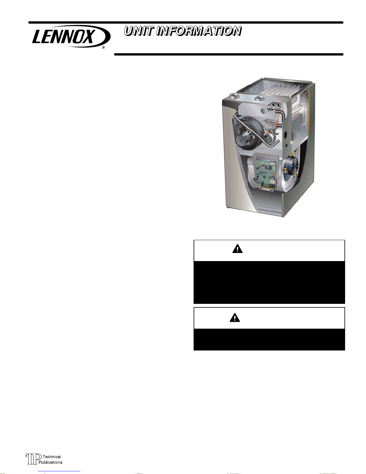
EL296UHE SERIES UNITS
EL296UHE series units are high efficiency condensing gas
furnaces used for upflow or horizontal applications only,
manufactured with Lennox Duralokt heat exchangers
formed of aluminized steel. EL296UHE units are available
in heating capacities of 44,000 to 132,000 Btuh and cooling
applications up to 5 tons. Refer to Product Specifications
Manual for proper sizing.
Units are factory equipped for use with natural gas. Kits are
available for conversion to LPG operation. EL296UHE
model units are equipped with the SureLight
integrated control. EL296UHE unit meets the California Ni
trogen Oxides (NO
Efficiency requirements. All units use a redundant gas
valve to assure safety shut-off as required by C.S.A.
All specifications in this manual are subject to change. Pro
cedures outlined in this manual are presented as a recom
mendation only and do not supersede or replace local or
state codes. In the absence of local or state codes, the
guidelines and procedures outlined in this manual (except
where noted) are recommendations only and do not consti
tute code.
Specifications Page 2.............................
I Unit Components Page 7........................
II Installation Page 22.............................
III Start Up Page 44..............................
IV Heating System Service Checks Page 45.........
V Typical Operating Characteristics Page 49.........
VI Maintenance Page 50..........................
VII Wiring and Sequence of Operation Page 53......
VIII Field Wiring and Jumper Settings Page 56.......
X Troubleshooting Page 60........................
) Standards and California Seasonal
x
TABLE OF CONTENTS
®
two-stage
EL296UHE
WARNING
Improper installation, adjustment, alteration, service
or maintenance can cause property damage, person
al injury or loss of life. Installation and service must
be performed by a licensed professional HVAC in
staller (or equivalent), service agency or the gas sup
plier.
WARNING
Sharp edges.
Be careful when servicing unit to avoid sharp edges
which may result in personal injury.
Page 1
© 2014 Lennox Industries Inc.
Page 2

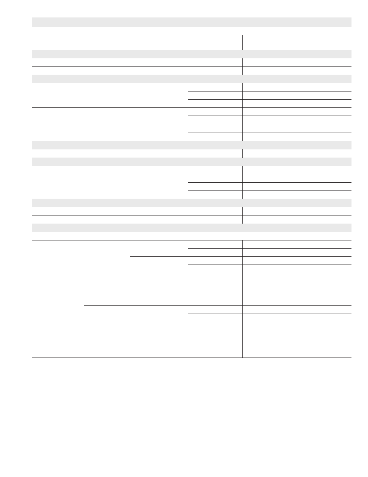
SPECIFICATIONS
Gas
Heating
Performance
High
Fire
Temperature rise range - °F 35-65 50-80 45-75
Gas Manifold Pressure (in. w.g.)
Nat. Gas / LPG/Propane
Low
Fire
Temperature rise range - °F 20 - 50 25 - 55 30 - 60
Gas Manifold Pressure (in. w.g.)
Nat. Gas / LPG/Propane
High static - in. w.g. Heating 0.5 0.5 0.5
Connections
Intake / Exhaust Pipe (PVC) 2 / 2 2 / 2 2 / 2
in.
Condensate Drain Trap (PVC pipe) - i.d. 3/4 3/4 3/4
with furnished 90° street elbow 3/4 slip x 3/4 Mipt 3/4 slip x 3/4 Mipt 3/4 slip x 3/4 Mipt
with eld supplied (PVC coupling) - o.d. 3/4 slip x 3/4 MPT 3/4 slip x 3/4 MPT 3/4 slip x 3/4 MPT
Indoor
Wheel nominal diameter x width - in. 10 x 8 10 x 8 10 x 10
Blower
Tons of add-on cooling 1.5 - 3 1.5 - 3 2.5 - 4
Air Volume Range - cfm 520 - 1345 550 - 1380 760 - 1740
Electrical Data Voltage 120 volts - 60 hertz - 1 phase
Blower motor full load amps 6.8 6.8 8.4
Maximum overcurrent protection 15 15 15
Shipping Data lbs. - 1 package 129 137 161
NOTE - Filters and provisions for mounting are not furnished and must be eld provided.
1
Annual Fuel Utilization Efciency based on DOE test procedures and according to FTC labeling regulations. Isolated combustion system rating for non-weatherized
furnaces.
Model No. EL296UH045XE36B EL296UH070XE36B EL296UH090XE48C
1
AFUE 96% 95.5% 95.7%
Input - Btuh 44,000 66,000 88,000
Output - Btuh 43,000 64,000 85,000
3.5 / 10.0 3.5 / 10.0 3.5 / 10.0
Input - Btuh 29,000 43,000 57,000
Output - Btuh 28,000 42,000 55,000
1.7 / 4.9 1.7 / 4.9 1.7 / 4.9
Cooling 0.5 0.5 0.5
Gas pipe size IPS 1/2 1/2 1/2
Motor output - hp 1/2 1/2 3/4
SPECIFICATIONS
Gas
Heating
Performance
High
Fire
Temperature rise range - °F 45-75 55-85
Gas Manifold Pressure (in. w.g.)
Nat. Gas / LPG/Propane
Low
Fire
Temperature rise range - °F 35 - 65 40 - 70
Gas Manifold Pressure (in. w.g.)
Nat. Gas / LPG/Propane
High static - in. w.g. Heating 0.5 0.5
Connections
Intake / Exhaust Pipe (PVC) 2 / 2 2 / 2
in.
Condensate Drain Trap (PVC pipe) - i.d. 3/4 3/4
with furnished 90° street elbow 3/4 slip x 3/4 Mipt 3/4 slip x 3/4 Mipt
with eld supplied (PVC coupling) - o.d. 3/4 slip x 3/4 MPT 3/4 slip x 3/4 MPT
Indoor
Wheel nominal diameter x width - in. 11-1/2 x 10 11-1/2 x 10
Blower
Tons of add-on cooling 3 - 5 3.5 - 5
Air Volume Range - cfm 1055 - 2220 1260 - 2405
Electrical Data Voltage 120 volts - 60 hertz - 1 phase
Blower motor full load amps 10.9 10.9
Maximum overcurrent protection 15 15
Shipping Data lbs. - 1 package 174 189
NOTE - Filters and provisions for mounting are not furnished and must be eld provided.
1
Annual Fuel Utilization Efciency based on DOE test procedures and according to FTC labeling regulations. Isolated combustion system rating for non-weatherized
furnaces.
Model No. EL296UH110XE60C EL296UH135XE60D
1
AFUE 96% 96%
Input - Btuh 110,000 132,000
Output - Btuh 106,000 127,000
3.5 / 10.0 3.5 / 10.0
Input - Btuh 72,000 86,000
Output - Btuh 70,000 84,000
1.7 / 4.9 1.7 / 4.9
Cooling 0.5 0.5
Gas pipe size IPS 1/2 1/2
Motor output - hp 1 1
Page 2
Page 3
OPTIONAL ACCESSORIES - ORDER SEPARATELY
NOTE - FURNACES CANNOT BE TWINNED!
“B” Width
Models
CABINET ACCESSORIES
Horizontal Suspension Kit - Horizontal only 51W10 51W10 51W10
Return Air Base - Upow only 50W98 50W99 51W00
CONDENSATE DRAIN KITS
Condensate Drain Heat Cable 6 ft. 26K68 26K68 26K68
24 ft. 26K69 26K69 26K69
50 ft. 26K70 26K70 26K70
Heat Cable Tape Fiberglass - 1/2 in. x 66 ft. 36G53 36G53 36G53
Aluminum foil - 2 in. x 60 ft. 16P89 16P89 16P89
Crawl Space Vent Drain Kit US 51W18 51W18 51W18
Canada 51W19 51W19 51W19
CONTROLS
Blower Relay Kit (for two-stage outdoor units) 85W66 85W66 85W66
FILTER KITS
1
Air Filter and
Rack Kit
Horizontal (end) Size of lter - in. 87L96 - 18 x 25 x 1 87L97 - 20 x 25 x 1 87L98 - 25 x 25 x 1
Side Return Single 44J22 44J22 44J22
Ten Pack 66K63 66K63 66K63
Size of lter - in. 16 x 25 x 1 16 x 25 x 1 16 x 25 x 1
SERVICE KITS
Night Service Kit 10B89 10B89 10B89
Universal Service Kit - Switches 89W20 89W20 89W20
TERMINATION KITS
See Installation Instructions for specic venting information.
Termination Kits Direct Vent
Applications Only
Termination Kits Direct or NonDirect vent
2
Roof Termination Flashing Kit - Direct or
Non-Direct Vent (2 ashings)
1
Cleanable polyurethane, frame-type lter.
5
Kits contain enough parts for two, non-direct vent installations.
3
Non-direct vent only.
NOTE - Termination Kits 44W92, 44W93, 30G28, 51W12, 51W19, 81J20 are certied to ULC S636 standard for use in Canada only.
Concentric US - 2 in. 71M80 69M29 - - -
3 in. - - - 60L46 60L46
Canada - 2 in. 44W92 44W92 - - -
3 in. - - - 44W93 44W93
Flush-Mount US - 2, 2-1/2 or 3 in. 51W11 51W11 51W11
Canada - 2, 2-1/2 or 3 in. 51W12 51W12 51W12
Wall - Close
Couple
Wall - Close
Couple WTK
US - 2 in. 22G44 - - - - - -
3 in. 44J40 44J40 44J40
Canada - 2 in. 30G28 - - - - - -
3 in. 81J20 81J20 81J20
Roof 2 in. 15F75 15F75 - - -
Wall Ring Kit 2 in. 15F74
2 in. 44J41 44J41 44J41
“C” Width
“D” Width
Models
3
15F74 - - -
Models
Page 3
Page 4
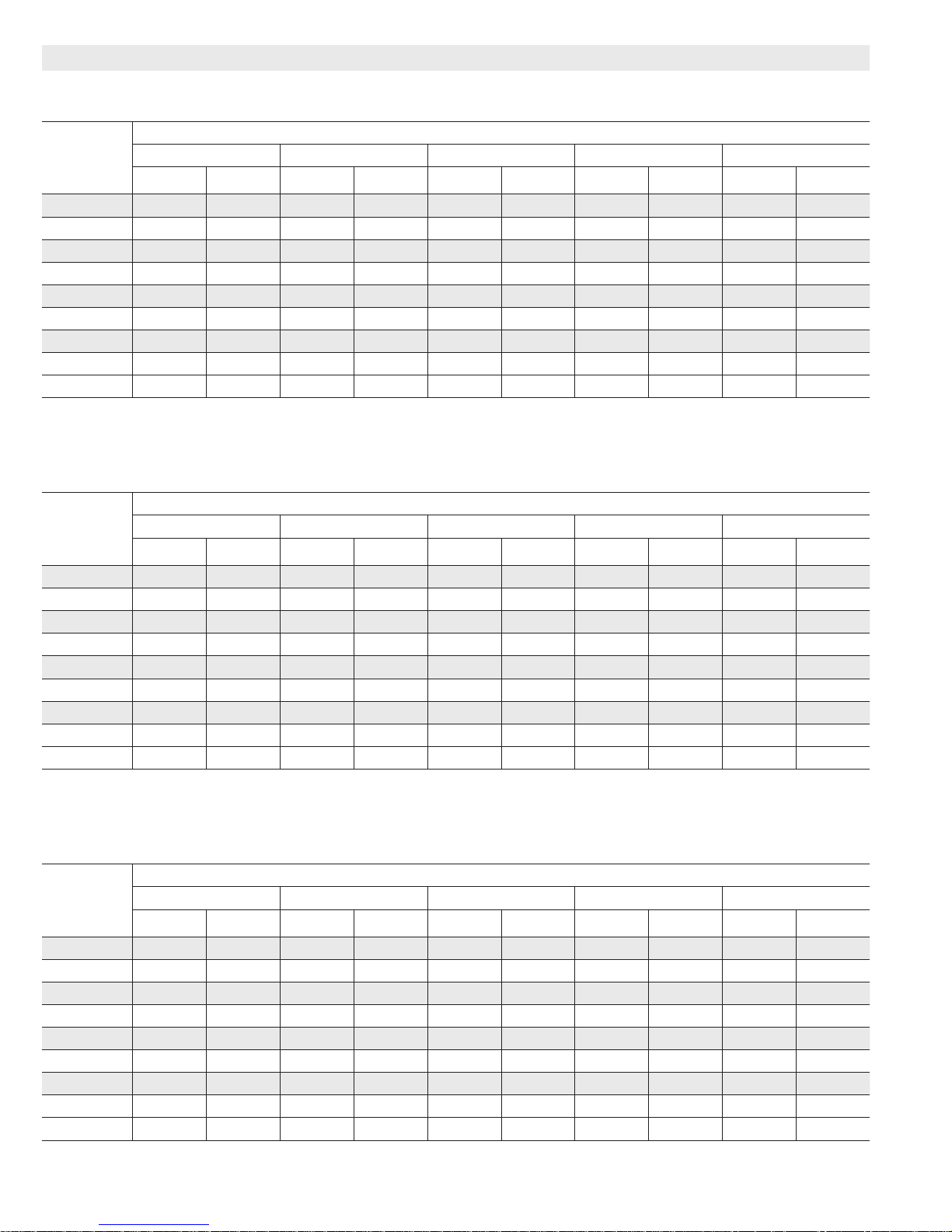
BLOWER DATA
EL296UH045XE36B PERFORMANCE (Less Filter)
External
Static
Pressure
in. w.g.
0.00 1345 340 1255 245 1150 185 895 105 845 95
0.10 1305 345 1225 250 1105 200 855 110 810 95
0.20 1290 360 1190 260 1080 205 825 120 780 105
0.30 1275 370 1150 270 1045 215 785 125 720 110
0.40 1220 385 1120 280 1015 220 735 135 690 120
0.50 1215 390 1090 290 980 230 705 140 635 125
0.60 1190 395 1060 300 950 240 650 150 600 135
0.70 N/A N/A 1015 300 900 250 620 155 555 140
0.80 N/A N/A 1000 310 870 260 580 160 520 145
EL296UH070XE36B PERFORMANCE (Less Filter)
External
Static
Pressure
in. w.g.
0.00 1380 315 1305 250 1190 200 965 105 920 100
0.10 1360 325 1270 255 1180 205 915 115 865 100
0.20 1310 335 1250 265 1130 215 880 120 815 110
0.30 1275 340 1205 275 1100 225 835 125 775 115
0.40 1250 355 1175 280 1065 230 795 135 730 125
0.50 1215 370 1145 295 1045 240 745 145 670 130
0.60 1200 380 1100 310 995 245 705 150 640 140
0.70 1145 380 1070 310 960 255 670 160 585 145
0.80 N/A N/A 1035 320 925 265 610 165 550 155
High Medium-High Medium Medium-Low Low
cfm Watts cfm Watts cfm Watts cfm Watts cfm Watts
High Medium-High Medium Medium-Low Low
cfm Watts cfm Watts cfm Watts cfm Watts cfm Watts
Air Volume / Watts at Various Blower Speeds
Air Volume / Watts at Various Blower Speeds
EL296UH090XE48C PERFORMANCE (Less Filter)
External
Static
Pressure
in. w.g.
0.00 1740 370 1505 250 1370 195 1285 160 1135 125
0.10 1695 390 1470 265 1325 205 1240 170 1090 135
0.20 1660 405 1435 280 1290 220 1195 185 1045 145
0.30 1615 415 1390 295 1240 235 1140 200 995 160
0.40 1590 425 1350 305 1200 245 111 0 210 945 165
0.50 1560 440 1310 320 1155 260 1055 225 895 175
0.60 1525 455 1255 335 1105 270 1005 230 855 190
0.70 1475 470 1220 340 1065 285 960 245 805 200
0.80 N/A N/A 1170 355 1010 295 920 255 760 210
High Medium-High Medium Medium-Low Low
cfm Watts cfm Watts cfm Watts cfm Watts cfm Watts
Air Volume / Watts at Various Blower Speeds
Page 4
Page 5
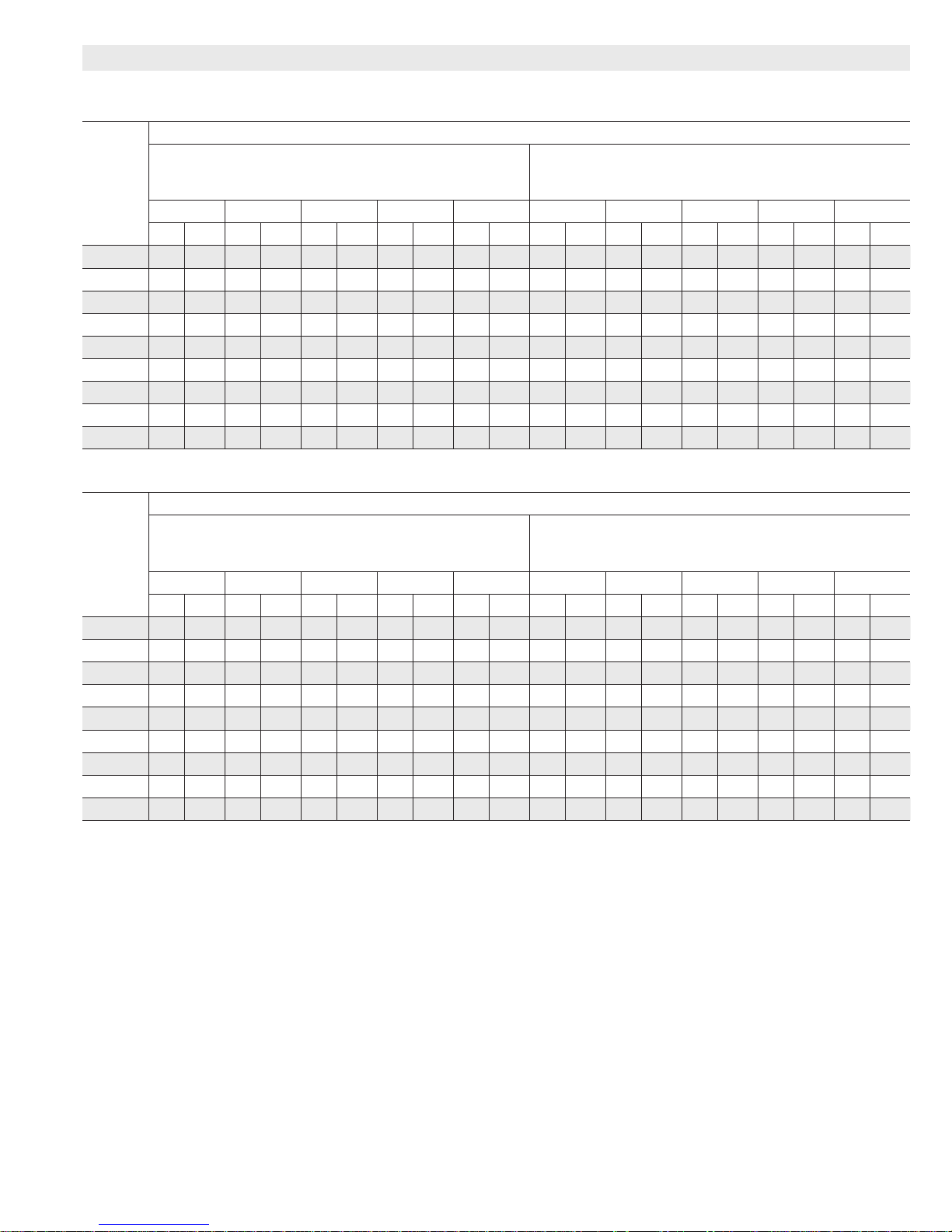
BLOWER DATA
EL296UH110XE60C PERFORMANCE (Less Filter)
Air Volume / Watts at Different Blower Speeds
External
Static
Pressure
in. w.g.
0.00 2220 645 1940 435 1765 335 1635 280 1435 200 2185 655 1915 440 1745 340 1620 275 1430 195
0.10 2170 660 1920 460 1715 350 1595 290 1380 205 2160 660 1880 460 1705 345 1570 285 1380 205
0.20 2130 680 1865 475 1670 370 1560 305 1345 220 2115 680 1835 470 1670 365 1535 305 1325 220
0.30 2095 700 1835 490 1640 390 1525 325 1285 230 2060 705 1795 495 1630 380 1505 320 1285 230
0.40 2065
0.50 2030 740 1755 525 1560 415 1425 355 1215 260 2000 740 1720 530 1535 415 1410 345 1195 260
0.60 1995 760 1705 550 1525 435 1380 370 1150 270 1955 760 1685 550 1505 435 1380 365 1145 275
0.70 1955 770 1660 560 1475 450 1350 375 1100 290 1935 775 1650 555 1455 450 1325 375 1100 285
0.80 1930 790 1635 575 1445 460 1300 395 1050 305 1890 790 1610 575 1425 460 1285 390 1055 295
EL296UH135XE60D PERFORMANCE (Less Filter)
External
Static
Pressure
in. w.g.
0.00 2405 940 2235 735 2070 545 1830 390 1620 280 2395 925 2235 710 2020 550 1800 380 1610 275
0.10 2365 960 2210 745 2020 565 1770 400 1585 295 2360 935 2175 735 2005 555 1760 395 1550 295
0.20 2330 975 2180 770 1950 580 1745 420 1535 315 2350 955 2160 760 1955 565 1725 415 1510 300
0.30 2295 1000 2120 785 1925 595 1690 435 1480 325 2290 990 2095 775 1890 590 1700 435 1420 325
0.40 2275
0.50 2225 1025 2035 815 1845 630 1605 475 1395 360 2230 1010 2040 815 1845 625 1590 470 1375 360
0.60 2185 1010 2020 835 1815 645 1565 485 1330 365 2170 1025 2000 820 1795 640 1580 485 1335 370
0.70 N/A N/A 1940 850 1735 665 1520 500 1310 385 N/A N/A 1935 845 1725 660 1520 500 1295 385
0.80 N/A N/A 1890 860 1715 680 1465 510 1285 400 N/A N/A 1880 855 1705 680 1470 510 1260 405
Bottom Return Air, Side Return Air with Optional Return
Air Base, Return Air from Both Sides or Return Air from
Bottom and One Side.
High Med-High Medium Med-Low Low High Med-High Medium Med-Low Low
cfm Watts cfm Watts cfm Watts cfm Watts cfm Watts cfm Watts cfm Watts cfm Watts cfm Watts cfm Watts
720 1785 510 1600 405 1465 335 1250 245 2050 720 1760 510 1570 400 1455 330 1235 245
Air Volume / Watts at Different Blower Speeds
Bottom Return Air, Side Return Air with Optional Return
Air Base, Return Air from Both Sides or Return Air from
Bottom and One Side.
High Med-High Medium Med-Low Low High Med-High Medium Med-Low Low
cfm Watts cfm Watts cfm Watts cfm Watts cfm Watts cfm Watts cfm Watts cfm Watts cfm Watts cfm Watts
1015 2075 805 1885 615 1640 460 1445 340 2255 995 2060 795 1850 615 1635 445 1390 340
Single Side Return Air − Air volumes in bold require eld
fabricated transition to accommodate 20 x 25 x 1 in. air lter
in order to maintain proper air velocity.
Single Side Return Air − Air volumes in bold require eld
fabricated transition to accommodate 20 x 25 x 1 in. air lter
in order to maintain proper air velocity.
Page 5
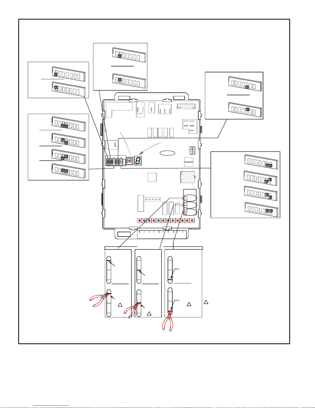
Page 6
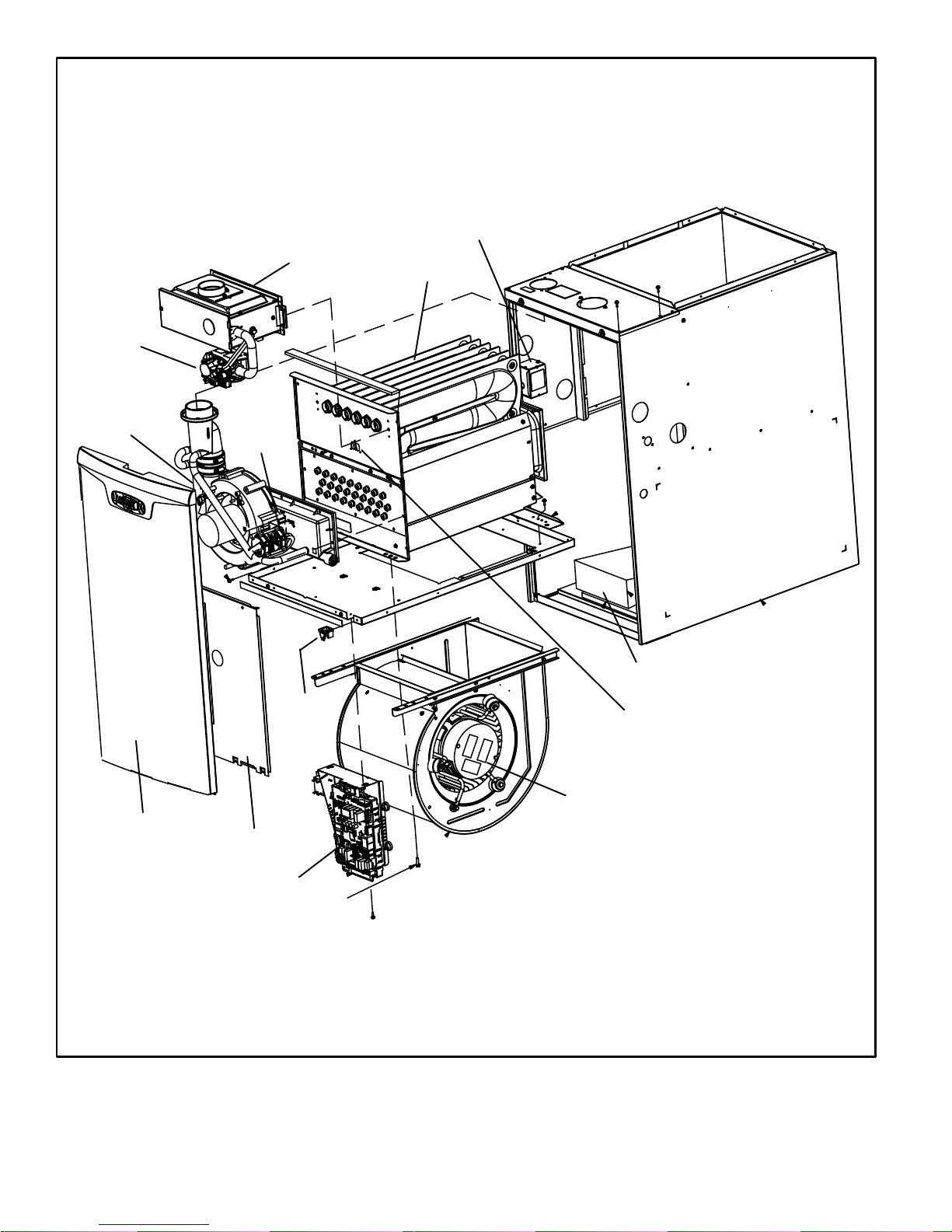
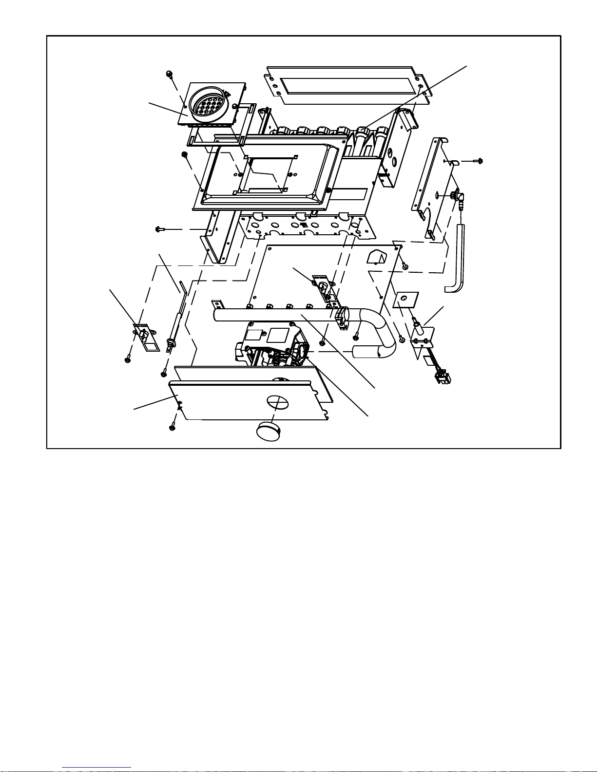
Gas Valve
EL296UHE PARTS IDENTIFICATION
Field Make Up Box
Burner Box Assembly
Heat Exchanger
Combustion
Air Inducer
Outer Access Panel
Pressure
Switch
Assembly
Door
Interlock
Switch
Inner Access Panel
Bag Assemblies
(shipping location)
Primary Limit
Constant Torque Indoor Blower Motor
Two-Stage Integrated Control
FIGURE 1
Page 6
Page 7
I-UNIT COMPONENTS
EL296UHE unit components are shown in figure 1. The
gas valve, combustion air inducer and burners can be ac
cessed by removing the access panel. Electrical compo
nents are in the control box (figure 2) found in the blower
section.
EL296UHE units are factory equipped with a bottom return
air panel in place. The panel is designed to be field re
moved as required for bottom air return. Markings are pro
vided for side return air and may be cut out in the field.
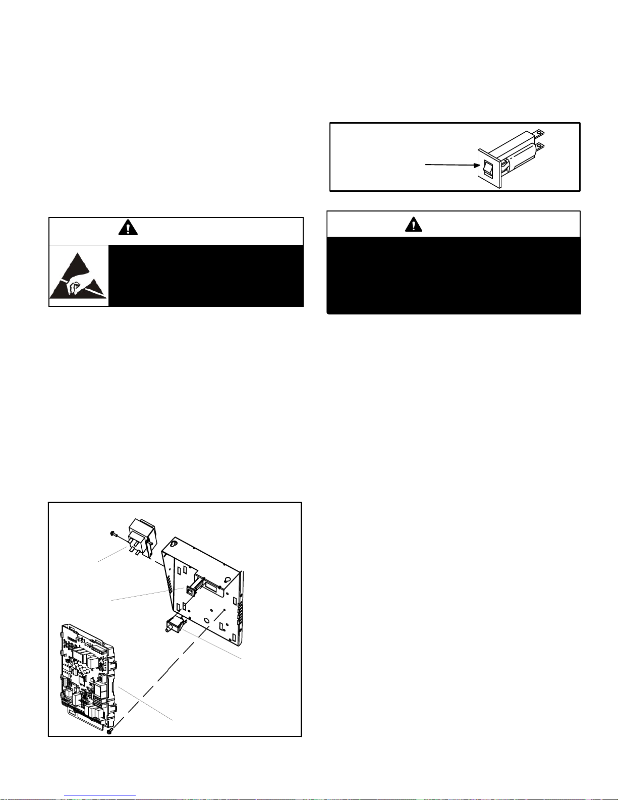
3. Circuit Breaker (CB8)
A 24V circuit breaker is also located in the control box. The
switch provides overcurrent protection to the transformer
(T1). The breaker is rated 3A at 32V. If the current exceeds
this limit the breaker will trip and all unit operation will shut
down. The breaker can be manually reset by pressing the
button on the face. See figure 3.
CIRCUIT BREAKER CB8
PRESS TO RESET
FIGURE 3
CAUTION
Electrostatic discharge can affect elec
tronic components. Take precautions
to neutralize electrostatic charge by
touching your hand and tools to metal
prior to handling the control.
A- Control Box
1. Control Transformer (T1)
A transformer located in the control box provides power to
the low voltage section of the unit. Transformers on all
models are rated 40VA with a 120V primary and a 24V sec
ondary.
2. Door Interlock Switch (S51)
A door interlock switch is wired in series with line voltage.
When the inner blower access panel is removed the unit
will shut down.
CONTROL BOX EL296UHE
Transformer
WARNING
Shock hazard.
Disconnect power before servicing. Integrated
control is not field repairable. If control is inoper
able, simply replace entire control.
Can cause injury or death. Unsafe operation will re
sult if repair is attempted.
4. Integrated Control (A92)
Units are equipped with the SureLight
grated control. The system consists of a ignition / blower
control (figures 4 and 5) with control pin designations in
tables 1 and 2 and ignitor (figure 14). The control and ignitor
work in combination to ensure furnace ignition and ignitor
durability. The control provides gas ignition, safety checks
and indoor blower control with two-stage gas heating. The
furnace combustion air inducer, gas valve and indoor blow
er are controlled in response to various system inputs such
as thermostat signal, pressure and limit switch signal and
flame signal. The control features a seven-segment LED
display, indicating furnace status and error codes. The
LED flashes in single digits. For example using table 4 un
der LIMIT CODE, an “E” followed by “2” followed by “5” fol
lowed by “0”, the limit switch circuit is open. The control also
has two unpowered (dry) 1/4” contacts for a humidifier and
a 120 volt accessory terminal. Both rated at (1) one amp
each.
®
two-stage, inte
Circuit Breaker
SureLight
FIGURE 2
Interlock Switch
®
Integrated Control
Electronic Ignition
At the beginning of the heat cycle the integrated control
monitors the first stage and second stage combustion air
inducer pressure switch. The control will not begin the
heating cycle if the first stage pressure switch is closed (bypassed). Likewise the integrated control will not begin the
second stage heating cycle if the second stage pressure
switch is closed, and will remain in first stage heat. Howev
er, if the second stage pressure switch closes during the
first stage heat pre-purge, the control will allow second
stage heat. Once the first stage pressure switch is deter
mined to be open, the combustion air inducer is energized
on low (first stage) heat speed. When the differential in the
pressure switch is great enough, the pressure switch
closes and a 15-second pre-purge begins.
Page 7
Page 8
®
After the 15-second pre-purge period, the SureLight
igni
tor warms up for 20 seconds after which the gas valve
opens for a 4-second trial for ignition. The ignitor remains
energized during the trial until flame is sensed. If ignition is
not proved during the 4-second period, the control will try
four more times with an inter purge and warm-up time be
tween trials of 35 seconds. After a total of five trials for igni
tion (including the initial trial), the control goes into Watch
guard-Flame Failure mode. After a 60-minute reset period,
the control will begin the ignition sequence again.
NOTE - During abnormal conditions such as low supply
voltage or low outdoor temperatures and the low fire pres
sure switch does not close, the combustion air inducer will
switch to high speed. After the low & high pressure switch
close, the unit will proceed with a 15 sec pre-purge, fol
lowed by a 20 sec ignitor warm up, then ignition on highfire. After 10 to 20 seconds of high fire operation the unit will
switch to low fire.
Two Stage Operation / Thermostat Selection DIP
Switch
The control can be utilized in two modes: SINGLE-STAGE
thermostat or TWO-STAGE thermostat. The thermostat
selection is made using a DIP switch and must be posi
tioned for the particular application. DIP switch 1, labeled
T”STAT HEAT STAGE is factory-set in the OFF position for
use with a two-stage thermostat. Move the DIP switch to
ON for use with a single stage thermostat.
While in the single-stage thermostat mode, the burners will
always fire on first-stage heat. The combustion air inducer
will operate on low speed and indoor blower will operate on
low heat speed. The unit will switch to second stage heat
after a “recognition period”. DIP switch 2, labeled SECOND
STAGE DELAY, is factory set in the OFF position for a 7
minute recognition period. The switch can be moved to the
ON position for a 12 minute recognition period, after which
time the unit will switch to second-stage heat. While in the
two-stage thermostat mode, the burners will fire on firststage heat. The combustion air inducer will operate on low
speed and indoor blower will operate on low heat speed.
The unit will switch to second-stage heat on call from the
indoor thermostat. If there is a simultaneous call for first
and second stage heat, the unit will fire on first stage heat
and switch to second stage heat after 30 seconds of opera
tion. See Sequence of Operation flow charts in the back of
this manual for more detail.
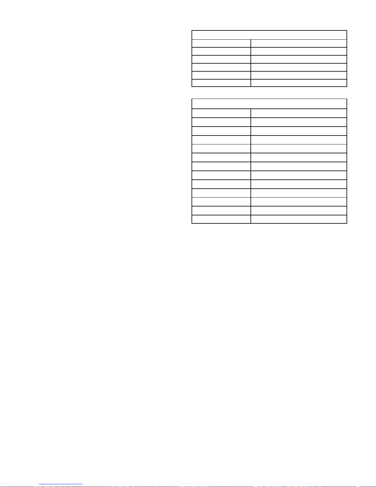
TABLE 1
SureLight
®
Control 5 Pin Terminal Designation
PIN # Function
1 Ignitor
2 Combustion Air Inducer High Speed
3 Combustion Air Inducer Low Speed
4 Combustion Air Inducer Neutral
5 Ignitor Neutral
TABLE 2
®
SureLight
Control 12 Pin Terminal Designation
PIN # Function
1 Gas Valve Second Stage
2 Second Stage pressure Switch
3 Rollout Switch In
4 Ground
5 24V Hot
6 Primary Limit In
7 Gas Valve First Stage
8 Gas Valve Common
9 24V Neutral
10 Ground
11 Primary Limit Out
12 First Stage pressure Switch
Page 8
Page 9
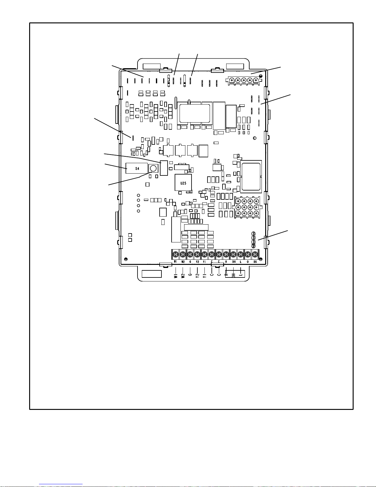
INTEGRATED CONTROL
24VAC Indoor
Blower Terminals
Flame Sense
LED
S4 DIP Switches
Diagnostic Push
Button
HUM
ACC
Ignitor and Combustion
Air Inducer
Neutrals
On Board Links
3/16” QUICK CONNECT TERMINALS
FLAME SENSE SIGNAL
HI COOL 24VAC
HI HEAT 24VAC
LO COOL 24VAC
LO HEAT 24VAC
PAR
PAR
K
COMMON 24VAC
K
1/4” QUICK CONNECT TERMINALS
NEUTRALS = 120 VAC NEUTRAL
HUM = UNPOWERED NORMALLY OPEN (DRY) CONTACTS
LI = 120 VAC INPUT TO CONTROL
ACC = 120 VAC OUTPUT TO OPTIONAL ACCESSORY
FIGURE 4
THERMOSTAT CONNECTIONS (TB1)
DS = DEHUMIDIFICATION SIGNAL
W2 = HEAT DEMAND FROM 2ND STAGE T/STAT
W1 = HEAT DEMAND FROM 1ST STAGE T/STAT
R = CLASS 2 VOLTAGE TO THERMO
G = MANUAL FAN FROM
C = THERMOSTAT SIGNAL GROUND CONNECTED TO
TRANSFORMER GRD (TR) & CHASIS GROUND (GRD)
Y1 = THERMOSTAT 1ST STAGE COOL SIGNAL
Y2 = THERMOSTAT 2ND STAGE COOL SIGNAL
O = THERMOSTAT SIGNAL TO HEAT PUMP
DH = NOT USED
L = NOT USED
STAT
T'STAT
REVERSING VALVE
Page 9
Page 10
THERMOSTAT SELECTION
1
2
*
TWO STAGE
THERMOSTAT
1−STAGE
THERMOSTAT
(TIMED STAGING)
−SEE SW #2
HEATING BLOWER−OFF DELAY
*
90 SECOND
HTG BLOWER
OFF DELAY
60 SECOND
HTG BLOWER
OFF DELAY
120 SECOND
HTG BLOWER
OFF DELAY
180 SECOND
HTG BLOWER
OFF DELAY
−BLOWER ON DELAY − 30 SEC. FIXED
3
ON
1
2
3
ON
1
2
3
ON
1
2
3
ON
1
2
3
ON
1
2
3
ON
INTEGRATED CONTROL CONFIGURATION GUIDE
2ND STAGE HEAT ON DELAY
1
2
3
4
5
6
7
COOLING BLOWER-OFF
5
N
P79
6
12
NEUTRALS
J2
DELAY
*45 SECOND
COOL BLOWER
OFF DELAY
2 SECOND
COOL BLOWER
OFF DELAY
LOW HEAT SPEED
LOW COOL SPEED
HIGH HEAT SPEED
HIGH COOL SPEED
1
2
3
4
5
ON
1
ON
6
7
2
3
4
5
6
7
CONTINUOUS FAN SETTINGS
1
2
3
4
5
ON
1
ON
1
ON
1
ON
6
2
3
4
5
6
7
2
3
4
5
6
7
2
3
4
5
6
7
7
2
3
4
5
6
7
HSI/CAI
L1
LED
1
J3
IGN
CAI2
®
110
4 7
3
SELECTION
N
CAI1
14
3
CUT FOR
OPTION
W915
2 STAGE
COMPR
W951
HEAT
PUMP
W914
DEHUM
ACC
HUM
DIAGNOSTIC
S1
7
SureLight
7 MIN
UPSTAGE
DELAY
12 MIN
UPSTAGE
DELAY
FLAME
SENSE
123456
ON
S4S3
ON
1
ON
DIAGNOSTIC
PUSH BUTTON
*
4
5
6
7
4
5
6
7
4
5
6
7
4
5
6
7
4
5
6
7
4
5
6
7
1−STG COMPRESSOR
W915
2 STAGE
COMPR
DO NOT CUT
2−STG COMPRESSOR
W915
2 STAGE
COMPR
CUT LINK
1
2−STAGE
COMPRESSOR LINK
(JUMPERS Y1 to Y2)
W915
W1W2 G Y2 Y1 C C DHL O DSR
W1
W2GY2
ON−BOARD LINK
OPTION SELECTION
A/C UNIT
W951
HEAT
PUMP
Y1
C
DO NOT CUT
HEAT PUMP UNIT
W951
HEAT
PUMP
CUT LINK
1
HEAT PUMP LINK
(JUMPERS R to O)
W951
FIGURE 5
C
L
R
DH
NO SIGNATURESTAT
W/ DS CONNECTION
DO NOT CUT
W914
DEHUM
SIGNATURESTAT W/
DS CONNECTION
CUT LINK
1
W914
DEHUM
DEHUMIFICATION LINK
(JUMPERS R to DS)
W914
−CUT ON−BOARD LINK (SOLDER TRACE) COMPLETELY THROUGH
1
BOTH LAYERS ON THE CONTROL BOARD
−LINKS CUT IN ERROR −INSTALL A JUMPER ON THE APPROPRIATE
TERMINALS ON THE TERMINAL STRIP
−PROTECTIVE PLASTIC FILM ON DIP SWITCHES MAY BE
REMOVED FOR EASE IN SETTING OF DIP SW.
* FACTORY DEFAULT
Page 10
Page 11
TABLE 3
Integrated Control Diagnostic Modes
Display Action (when button released)
No change (idle)* Remain in idle mode
Solid “E” Enter diagnostic recall mode
Solid “F” Enter flame signal mode
TABLE 4
Integrated Diagnostic Codes/Status of Equipment
Code Diagnostic Codes/Status of Equipment Action Required to Clear and Recover
.
Idle mode (Decimal blinks at 1 Hertz -- 0.5 second ON, 0.5 second OFF).
C
Cooling stage (1 second ON, 0.5 second OFF) 1 or 2 displayed / Pause
/ Repeat codes.
d
Dehumidification mode (1 second ON, 1 second OFF) / Pause / Repeat
Codes).
H
Gas Heat Stage (1 second ON, 0.5 second OFF) 1 or 2 displayed /
Pause / Repeat codes. Blinking during ignition.
h
Heat pump stage.
E 110
Low line voltage. Line Voltage Low (Voltage lower than nameplate
rating). Check power line voltage and correct. Alarm
clears 5 seconds after fault recovered.
E 111
Line voltage polarity reversed. Reverse line power voltage wiring. System resumes
normal operation 5 seconds after fault recovered.
E 112
Ground not detected System shuts down. Provide proper earth ground.
System resumes normal operation 5 seconds after
fault recovered.
E 113
High line voltage. Line Voltage High (Voltage higher than nameplate
rating). Provide power voltage within proper range.
System resumes normal operation 5 seconds after
fault recovered.
E 114
Line voltage frequency out-of-range. No 60 Hertz Power. Check voltage and line power
frequency. Correct voltage and frequency problems.
System resumes normal operation 5 seconds after
fault recovered.
E 115
Low 24V - Control will restart if the error recovers. 24-Volt Power Low (Range is 18 to 30 volts). Check
and correct voltage. Check for additional power-rob
bing equipment connected to system. May require
installation of larger VA transformer to be installed
in furnace / air handler. Clears after fault recovered.
E 117
Poor ground detected (Warning only) Provide proper grounding for unit. Check for proper
earth ground to the system. Warning only will clear
30 seconds after fault recovered.
* No change implies the display will continue to show whatever is currently being displayed for normal operation (blinking decimal, active error code, heat state, etc..)
Diagnostic LED (Figure 4)
The seven-segment diagnostic LED displays operating
status, error codes and other information. The table begin
ning on Page 11 lists diagnostic LED codes.
Diagnostic Push Button (Figure 4)
The diagnostic push button is located adjacent to the
seven-segment diagnostic LED. This button is used to en
able the Error Code Recall “E” mode and the Flame Signal
“F” mode. Press the button and hold it to cycle through a
menu of options. Every five seconds a new menu item will
be displayed. When the button is released, the displayed
item will be selected. Once all items in the menu have been
displayed, the menu resumes from the beginning until the
button is released.
Error Code Recall Mode
Select ”E” from the menu to access the most recent 10 error
codes. Select “c” from the Error Code Recall menu to clear
all error codes. Button must be pressed a second time
while “c” is flashing to confirm command to delete codes.
Press the button until a solid “≡” is displayed to exit the Error
Code Recall mode.
Flame Signal Mode
Select ”F” from the menu to access the flame signal mode.
The integrated control will display the flame current on
seven-segment LED in in micro amps (uA).
Flame signal mode is exited after any of the following:
D Power is reset
D Pressing and holding push button until 3 horizontal
lines “≡” are displayed
D 10 minutes after entering the flame sense mode.
Page 11
Page 12

E 125
E 200
E 204
E 205
E 206
E 207
E 223
E 224
E 225
E 226
E 227
E 229
E 240
E 241
E 250
TABLE 4 Continued
Control failed self-check, internal error, failed hardware. Will restart if
error
recovers. Integrated control not communicating. Covers hardware errors
(flame sense circuit faults, pin shorts, etc.).
Hard lockout - Rollout circuit open or previously open. Correct cause of rollout trip, or replace flame rollout
Gas valve mis-wired. Check gas valve operation and wiring. Clears when
Gas valve control relay contact shorted. Check wiring on control and gas valve. If wiring is
Gas valve second-stage relay failure Furnace will operate on 1st stage for remainder of
Hot surface ignitor sensed open Measure resistance of hot surface ignitor. Replace
Low pressure switch failed open. Check pressure (inches w.c.) of low pressure switch
Low pressure switch failed closed. Check operation of low pressure switch to see if it is
High pressure switch failed open. Check pressure (inches w.c.) of high pressure
High pressure switch failed closed. Check operation of high pressure switch closing on
Low pressure switch open during trial for ignition or run mode. Check pressure (inches w.c.) of low pressure switch
Ignition on High Fire - Information Only. Code is displayed if 1) low pressure switch fails to
Low flame current - Run mode. Check micro-amperes of flame sensor using control
Flame sensed out of sequence - Flame still present. Shut off gas. Check for gas valve leak. Replace, if
Limit switch circuit open. Check for proper firing rate on furnace. Ensure
Hardware problem on the control. Cycle power on
control. Replace if problem prevents service and is
persistent. Critical alert. Cleared 300 seconds after
fault recovered.
switch. Test furnace operation. Cleared after fault
recovered.
repaired.
correct, replace control.
the heating demand. Will clear after fault recovered.
If unable to operate 2nd stage, replace control.
if open or not within specified range found in IOM.
Resumes normal operation after fault is cleared.
closing on heat call. Measure operating pressure
(inches w.c.). Inspect vent and combustion air in
ducer for correct operation and restriction. Re
sumes normal operation after fault is cleared
stuck closed on heat call longer than 150 seconds.
Measure operating pressure (inches w.c.). Inspect
vent and combustion air inducer for correct opera
tion and restriction. Resumes normal operation after
fault is cleared.
switch closing on heat call. Measure operating pres
sure (inches w.c.). Inspect vent and combustion air
inducer for correct operation and restriction. Re
sumes normal operation after fault is cleared.
heat call. Measure operating pressure (inches w.c.).
Inspect vent and combustion air inducer for correct
operation and restriction. Resumes normal opera
tion after fault is cleared.
closing on heat call. Measure operating pressure
(inches w.c.). Inspect vent and combustion air in
ducer for correct operation and restriction. Re
sumes normal operation after fault is cleared.
close, then furnace will switch to high speed inducer
to close both low and high pressure switches, then
furnace lights on high fire, or 2) if continuous fan is
active, furnace lights on high fire for 60 seconds to
improve heat exchanger warm up time.
diagnostics or field-installed mode. Clean or replace
sensor. Measure voltage of neutral to ground to
ensure good unit ground. Alert clears after current
heat call has been completed.
necessary. Alert clears when fault is recovered.
there is no blockage in heater. Check for proper air
flow. If limit not closed within 3 minutes, unit will go
into 1-hour soft lockout. Resumes normal operation
after fault is cleared.
Page 12
Page 13
TABLE 4 Continued
E 270
Soft lockout - Exceeded maximum number of retries. No flame current
sensed.
Code Diagnostic Codes/Status of Equipment Action Required to Clear and Recover
E 271
Soft lockout - Exceeded maximum number of retries. Last retry failed due
to the pressure switch opening.
E 272
Soft lockout - Exceeded maximum number of recycles. Last recycle due
to the pressure switch opening.
E 273
Soft lockout - Exceeded maximum number of recycles. Last recycle due
to flame failure.
E 274
Soft lockout - Exceeded maximum number of recycles. Last recycle
failed due to the limit circuit opening or limit remained open longer than
3 minutes.
E 275
Soft lockout - Flame sensed out of sequence. Flame signal is gone. Shut off gas. Check for gas valve leak. 1-hour soft
E 290
Ignitor circuit fault - Failed ignitor or triggering circuitry. Measure resistance of hot surface ignitor. Replace
Check for proper gas flow. Ensure that ignitor is
lighting burner. Check flame sensor current. Clears
when heat call finishes successfully.
Check pressure (inches w.c.) of low pressure switch
closing on heat call. Measure operating pressure
(inches w.c.). Inspect vent and combustion air in
ducer for correct operation and restriction. Clears
when heat call finishes successfully.
Check operation of low pressure switch to see if it is
stuck closed on heat call. Check pressure (inches
w.c.) of high pressure switch closing on heat call.
Measure operating pressure (inches w.c.). Inspect
vent and combustion air inducer for correct opera
tion and restriction. Clears when heat call finishes
successfully.
Check micro-amperes of flame sensor using control
diagnostics or field-installed mode. Clean or replace
sensor. Measure voltage of neutral to ground to
ensure good unit ground. Clears when heat call
finishes successfully.
Shut down system. 1-hour soft lockout. Check firing
rate and air flow. Check for blockage. Clears when
heat call finishes successfully.
lockout. Clears when flame has been proven stable.
if open or not within specifications. 1-hour soft lock
out. Clears when flame has been proven stable.
Page 13
Page 14
Integrated Control DIP Switches
EL296UHE units are equipped with a two-stage integrated
control. This control manages ignition timing, heating
mode fan off delays and indoor blower speeds based on
selections made using the control dip switches and jump
ers. The control includes an internal watchguard feature
which automatically resets the ignition control when it has
been locked out. After one hour of continuous thermostat
demand for heat, the watchguard will break and remake
thermostat demand to the furnace and automatically reset
the control to relight the furnace.
Heating Operation DIP Switch Settings
Switch 1 -- Thermostat Selection -- This unit may be
used with either a single-stage or two-stage thermostat.
The thermostat selection is made using a DIP switch which
must be properly positioned for the particular application.
The DIP switch is factory-positioned for use with a twostage thermostat. If a single-stage thermostat is to be used,
the DIP switch must be repositioned.
a-a -Select “OFF” for two-stage heating operation con
trolled by a two-stage heating thermostat (factory set
ting);
b - Select “ON” for two-stage heating operation con
trolled by a single-stage heating thermostat. This set
ting provides a timed delay before second-stage heat
is initiated.
Switch 2 a --- Second Stage Delay (Used with SingleStage Thermostat Only) -- This switch is used to deter
mine the second stage on delay when a single-stage ther
mostat is being used. The switch is factory-set in the OFF
position, which provides a 7-minute delay before secondstage heat is initiated. If the switch is toggled to the ON
position, it will provide a 12-minute delay before secondstage heat is initiated. This switch is only activated when
the thermostat selector jumper is positioned for SINGLEstage thermostat use.
Indoor Blower Operation DIP Switch Settings
Switches 3 and 4 -- Heating Mode Blower-Off Delay --
The blower-on delay of 30 seconds is not adjustable. The
blower-off delay (time that the blower operates after the
heating demand has been satisfied) can be adjusted by
moving switches 3 and 4 on the integrated control. The unit
is shipped from the factory with a blower-off delay of 90 se
conds. The blower off delay affects comfort and is adjust
able to satisfy individual applications. Adjust the blower off
delay to achieve a supply air temperature between 90° and
110°F at the exact moment that the blower is de-energized.
Longer off delay settings provide lower supply air tempera
tures; shorter settings provide higher supply air temperatu
res.Table 5 provides the blower off timings that will result
from different switch settings.
Blower Off Heating Mode Delay Switch Settings
Blower Off Delay
(Seconds)
60 On Off
90 (Factory) Off Off
120 Off On
180 On On
Switch 5 -- Cooling Mode Blower-Off Delay-- The unit is
shipped from the factory with the dip switch positioned OFF
for a 45 second delay. Table 6 provides the cooling mode
off delay settings.
Blower Off Cooling Mode Delay Switch Settings
Blower Off Delay
(Seconds)
45 (Factory) Off
2 On
Switches 6 and 7 -- Continuous Fan Mode -- Continuous
fan speed can be controlled by changing DIP switch posi
tions. Table 7 below provides DIP switch settings for con
tinuous fan mode.
Continuous Fan Mode Settings
Continuous Fan
Mode
Low Heat Speed
(factory)
Low Cool Speed Off On
High High Speed On Off
High Cool Speed On On
TABLE 5
Switch 3 Switch 4
TABLE 6
Switch 5
TABLE 7
Switch 6 Switch 7
Off Off
Onboard Links
W914 Dehum
Onboard link W914, is a clippable connection between ter
minals R and DS on the integrated control. W914 must be
cut when the furnace is installed with a thermostat which
features humidity control. If the link is not cut, terminal “DS'
will remain energized not allowing the blower to reduce to
low cool speed upon a call for dehumidification.
W951 Heat Pump (R to O)
Onboard link W951 is a clippable connection between ter
minals R and O on the integrated control. W951 must be cut
when the furnace is installed in applications which include a
heat pump unit and a thermostat which features dual fuel
use. If the link is left intact, terminal “O” will remain ener
gized eliminating the HEAT MODE in the heat pump.
W915 2 Stage Compr (Y1 to Y2)
Onboard link W915 is a clippable connection between ter
minals Y1 and Y2 on the integrated control. W915 must be
cut if two-stage cooling will be used. If the Y1 to Y2 link is
not cut the outdoor unit will operate in second-stage cool
ing only.
IMPORTANT
If any onboard link is cut by mistake, install a jump
er across the corresponding terminals on the low
voltage terminal strip. Do not replace control.
Page 14
Page 15
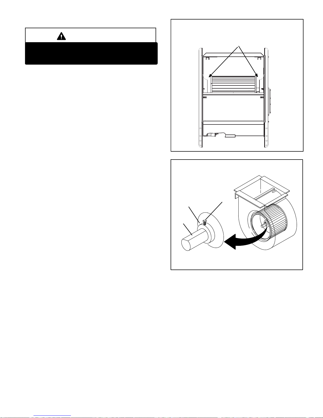
B- Indoor Blower Motor
BLOWER WHEEL REPLACEMENT
IMPORTANT
Each blower is statically and dynamically bal
anced as an assembly before installation in the
unit.
EL296UHE units are equipped with a constant torque ECM
motor. It has a DC motor coupled to an electronic control
module both contained in the same motor housing. The
motor is programmed to provide constant torque at each of
the five selectable speed taps. Each tap requires 24 volts to
energize.
Input Voltage Requirements
The circuit is designed to be operated with AC voltage. To
enable a tap requires 12 to 33VAC. Expected current draw
will be less than 20mA.
Troubleshooting the Motor
Troubleshooting the motor is an easy process. Follow
steps below.
1- Shut off power to unit.
Center Blower Wheel
in Blower Housing
FIGURE 6
ALIGN AND TIGHTEN SET SCREW WITH
FLAT SIDE OF MOTOR SHAFT
2- Remove input plugs P48 and P49 from motor. See fig
ure 8 for troubleshooting procedure.
If correct voltage is present in tests 1 and 2 and motor is not
operating properly, replace motor. The motor is not field re
pairable.
If replacing the indoor blower motor or blower wheel is nec
essary, placement is critical. The blower wheel must be
centered in the blower housing as shown in figure 6. When
replacing the indoor blower motor the set screw must be
aligned and tightened with the motor shaft as shown in fig
ure 7.
Housing Hub
Motor
Shaft
Set Screw
FIGURE 7
Page 15
Page 16
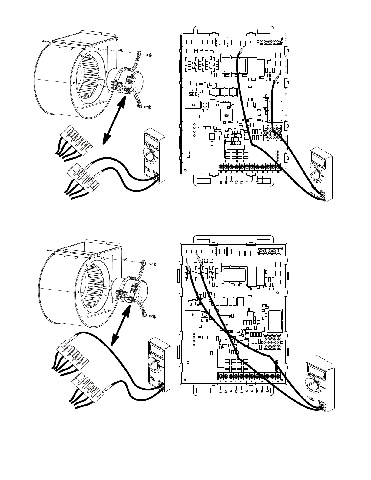
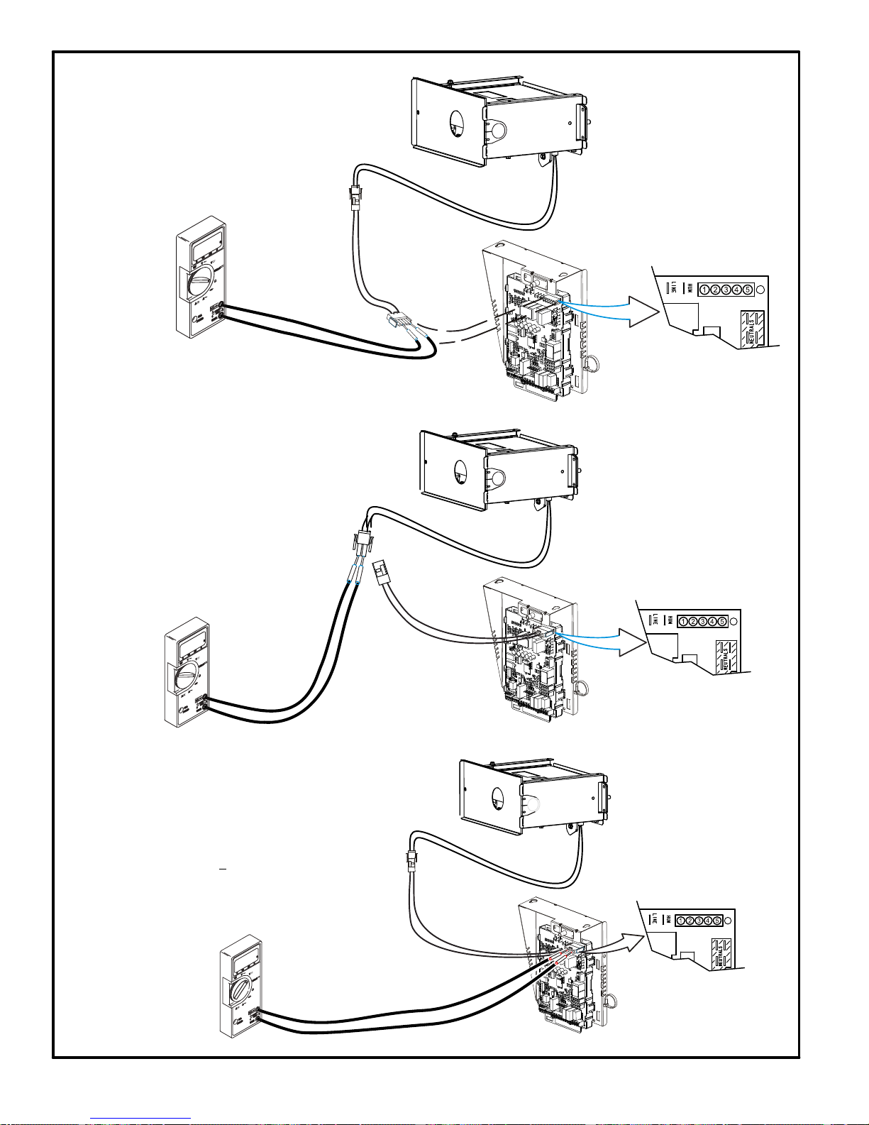
Multi−Meter
r
)
r
)
P49
5
4
3
2
1
N
G
L
C
Test 1
Turn on power to unit. Check for 120 volts across terminals “L”
and “N” on input plug P48. If voltage is present continue to test
2. If voltage is not present problem may be may be upstream
of plug P48 and proceed to test 3.
P48
(set to VAC)
12012
0
Multi−Mete
(set to VAC
12012
Test 3 (if necessary)
Check for 120 volts across terminals “L1” and “Neutrals” on the
integrated control. If voltage is present, problem is with the har
ness. If voltage is not present problem may be may be with the
integrated control.
0
P49
5
4
3
2
1
N
G
L
C
P48
Test 2
Switch thermostat to CONTINUOUS FAN MODE. Check for 24
volts across terminal “C” on input plug P48and speed tap used for
continuous fan. (1, 2, 3, 4 or 5) on input plug P49. If 24 volts is not
present problem may be up stream of plug P49. Proceed to test
4.
Multi−Meter
(set to VAC)
24
FIGURE 8
Page 16
Multi−Mete
(set to VAC
24
Test 4 (if necessary)
Check for 24 volts across terminals “24 COM” and the “active
speed tap” on the integrated control. If voltage is present, prob
lem is with the harness. If voltage is not present problem may
be may be with the integrated control
Page 17
Replacing the Motor Module
1. Disconnect electrical power to unit.
2. Remove unit access panel.
3. Unplug the two harnesses from the motor control mod
ule. See figure 9.
Unplug the Two Harness Connection
Motor Test
TWO HARNESS
CONNECTIONS
MOTOR
MOTOR CONTROL MODULE
FIGURE 9
4. Remove the two hex head bolts securing the motor
control module to the motor (see figure 10).
Remove the Hex Head Bolts
REMOVE BOTH HEX
HEAD BOLTS
FIGURE 10
5. Slide the motor control module away from the motor to
access and disconnect the internal three wire connec
tor. It is not necessary to remove blower motor itself.
Set both hex head bolts aside.
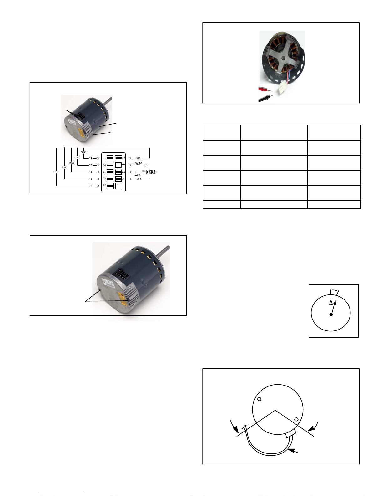
Testing the Motor (Figure11)
FIGURE 11
TABLE 8
Scale
2 M
200 K
20 K
2 K
200 two hundred ohms 0 - 200
Measurement range in
words
two megohm-two million
ohms
two hundred kilo-ohm-two
hundred thousand ohms
twenty kilo-ohm-twenty
thousand ohms
two kilo-ohm two-thousand
ohms
ohms
0 - 2,000,000
0 - 200,000
0 - 20,000
0 - 2,000
Motor Module Installation
All replacement motor control modules look similar; how
ever, each module is designed for a specific motor size. It is
very important to make sure that you are using the correct
replacement motor control module. USE OF THE WRONG
MOTOR CONTROL MODULE MAY RESULT IN UNEX
PECTED UNIT OPERATION.
1. Verify electrical power to unit is disconnected.
2. Connect three-wire harness from motor to control
module.
3. Mount new motor control module
to motor using two hex head bolts
removed in figure 10. Torque bolts
to 22 inch pounds or 1/16
th
clock
turn as exampled to the right.
4. Reconnect the two harnesses to
9
10
8
11
7
12
6
1
5
1/16
TURN
2
3
4
the motor control module.
5. The electrical connectors of the motor should be facing
down to form a drip loop (figure12). This will directs
moisture away from the motor and its electric connec
tions on the motor.
Drip Loop
If any motor fails the below tests, do not install the new con
trol module. The motor is defective and it also must be re
placed. The new control can fail if placed on a defective mo
tor.
1. Using an ohmmeter check the resistance from any one
of the motor connector pins to the aluminum end plate
of the motor. This resistance should be greater than
100k ohms.
2. Check the resistances between each of the three mo
tor connector pins. These should all read approxim
ately the same resistance within an ohm.
3. Check to see if the blower wheel spins freely.
Page 17
BACK OF CONTROL
MODULE
FIGURE 12
CONNECTOR
ORIENTATION
BETWEEN 4 AND 8
O'CLOCK
DRIP LOOP
Page 18
C- Heating Components
1. Ignitor
®
The SureLight
ignitor is made of durable silicon nitride.
The integrated control provides 120 volts to the ignitor for a
consistent ignition and long ignitor life. Ohm value should
be 39 to 70. See figure 14 for ignitor location and figure 15
for ignitor check out.
NOTE - The EL296UHE furnace contains electronic com
ponents that are polarity sensitive. Make sure that the fur
nace is wired correctly and is properly grounded.
2. Flame Sensor
A flame sensor is located on the left side of the burner sup
port. See figure 14. The sensor tip protrudes into the flame
envelope of the left-most burner. The sensor can be re
moved for service without removing any part of the burn
ers. During operation, flame is sensed by current passed
through the flame and sensing electrode. The SureLight
control allows the gas valve to remain open as long as
flame signal is sensed. To check flame sense signal use
the push-button found on the integrated control and go to
Field Test Mode. The menu will display the flame signal.
See table 9 for flame signal.
TABLE 9
Flame Signal in Microamps
Normal
Low Drop Out
2.6 or greater 2.5 or less 0.6
3. Gas Valve
The valve (figure 14) is internally redundant to assure safe
ty shut-off. If the gas valve must be replaced, the same type
valve must be used.
24VAC terminals and gas control knob are located on the
valve. A wire harness connects the terminals from the gas
valve to the electronic ignition control. 24V applied to the
terminals energizes the valve.
Inlet and outlet pressure taps are located on the valve. A
regulator adjustment screw is located on the valve.
LPG change over kits are available from Lennox. Kits in
clude burner orifices and a gas valve.
caused by a blocked heat exchanger, flue or lack of com
bustion air. The switch is factory set to trip (open) at 210°F
and cannot be adjusted. The switch can be manually reset.
To manually reset a tripped switch, push the reset button
located on the control.
5. Burners
All units use inshot burners. Burners are factory set and re
quire no adjustment. Always operate the unit with the burn
er box front panel in place. Each burner uses an orifice that
is precisely matched to the burner input. Burners can be re
moved as a one piece assembly for service. If burner as
sembly has been removed, it is critical to align center of
each burner to the center of the clamshell when re-instal
ling. See more detail in Section VI- MAINTENANCE.
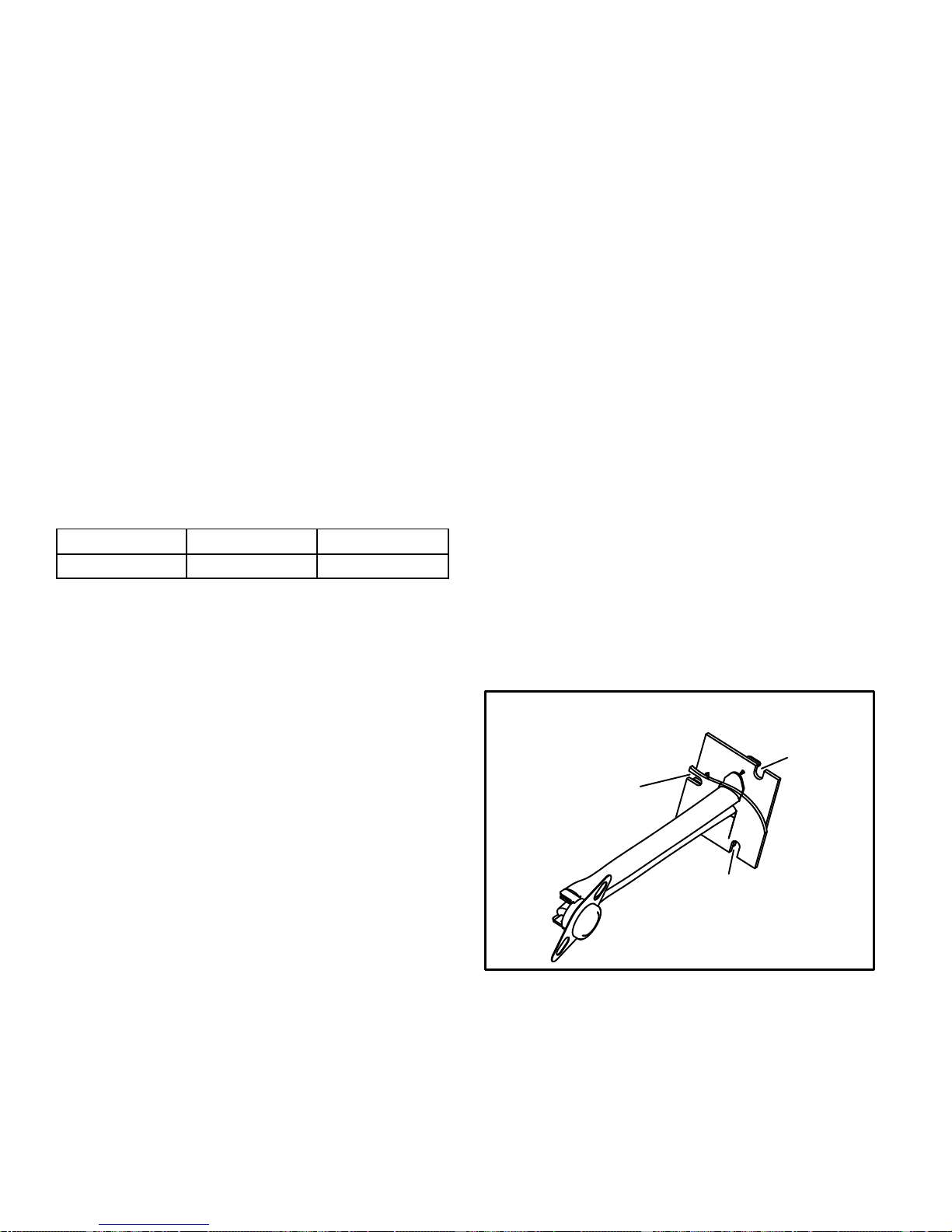
6. Primary Limit Control (S10)
The primary limit (S10) is located in the heating vestibule
panel. When excess heat is sensed in the heat exchanger,
the limit will open. If the limit is open, the furnace control en
ergizes the supply air blower and closes the gas valve. The
limit automatically resets when unit temperature returns to
normal. The switch must reset within three minutes or the
SureLight control will go into Watch guard for one hour.
The switch is factory set and cannot be adjusted.
The switch may have a different set point for each unit mod
el number. See Lennox Repair Parts Handbook if limit
switch must be replaced. When removing switch make
note of orientation. When replacing switch make sure the
three mounting holes are lined up with the screw holes in
the vestibule for correct orientation.
Primary Limit Control (S10)
Mounting Hole
Mounting Hole
4. Flame Rollout Switches (S47)
Flame rollout switch is a high temperature limit located on
top of the burner box, one on each side.- See figure 14. The
limit is a N.C. SPST manual‐reset limit. When S47 senses
rollout, the circuit breaks and the ignition control immedi
ately stops ignition and closes the gas valve. Rollout can be
Mounting Hole
FIGURE 13
Page 18
Page 19
Intake Air Top Cap
Rollout Switch
EL296UHE HEATING COMPONENTS
Burner Assembly
Sensor
Rollout Switch
Ignitor
Burner Box Cover
Manifold And Gas Orifices
Two-Stage Gas Valve
FIGURE 14
Page 19
Page 20
Check ignitor circuit for correct resistance.
Test 1
Remove 5-pin plug from control.
Check ohms reading across terminals 1 and 5.
Reading should be between 39 and 70 ohms. If
value is correct, this is the only test needed.
If the reading on the meter is not correct, (0 or
infinity) then a second test is needed.
Meter
(set to ohms)
EL296UHE Ignitor Check
Integrated Control Detail
Seperate the 2-pin jack-plug near the manifold and check
Check ignitor for correct resistance.
resistance of ignitor at the plug. Reading should be
between 39 and 70 ohms. If the reading is correct, then
the problem is with the wiring between the jack-plug and
the control. If reading is not correct, the issue is the ignitor.
Test 2
Meter
(set to ohms)
Insert meter probes into terminals 1 and 5 (use small
Check ignitor for correct voltage
diameter probes in order not to damage plug).
Check voltage during 20 second ignitor warm up period.
Voltage should read 120 volts +
these values, check for correct supply voltage to furnace.
Test 3
10%. If voltage reads below
Integrated Control Detail
Meter
(set to AC volts)
Integrated Control Detail
FIGURE 15
Page 20
Page 21

7. Combustion Air Inducer (B6) and
Cold End Header Box
All EL296UHE units use a two-speed combustion air induc
er to move air through the burners and heat exchanger dur
ing heating operation. The blower uses a 120VAC motor.
The motor operates during all heating operation and is con
trolled by integrated control control A92. The inducer also
operates for 15 seconds before burner ignition (pre‐purge)
and for 5 seconds after the gas valve closes (post‐purge).
The inducer operates on low speed during first-stage heat,
then switches to high speed for second stage heat.
The combustion air inducer is installed on the cold end
header box (CEHB). The cold end header box is a single
piece made of hard plastic. The box has an internal chan
nel where the combustion air inducer creates negative
pressure at unit start up. The channel contains an orifice
used to regulate flow created by the combustion air induc
er. The box has pressure taps for the combustion air induc
er pressure switch hoses. The pressure switch measures
the pressure differential across the cold end header box
orifice or difference in the channel and the box. If replace
ment is necessary the gaskets used to seal the box to
the vestibule panel and the combustion air inducer to
the box, must also be replaced.
A pressure switch measures the pressure differential
across the CEHB orifice to prove inducer operation. The
CEHB orifice will be different for each model. See table 10
for orifice sizes. When the proving switch opens, the fur
nace control (A92) immediately closes the gas valve to pre
vent burner operation.
TABLE 10
EL296UHE Unit
CEHB Orifice Size
-045 0.618
-070 0.810
-090 0.920
-110 1.040
-135 1.235
8. Combustion Air Inducer Pressure Switch (S18)
(Figure 16)
EL296UHE series units are equipped with a dual combus
tion air pressure switch (first and second stage) located on
the CEHB. The switch is connected to the cold end header
box by means of flexible silicone hoses. It monitors nega
tive differential pressure across the cold end header box
orifice.
The switches are a single‐pole single‐throw pressure
switches electrically connected to the integrated control.
The purpose of the switches is to prevent burner operation
if the combustion air inducer is not operating, the inlet or ex
haust pipes or heat exchanger are restricted.
On heat demand (first or second stage) the switch senses
that the combustion air inducer is operating. It closes a cir
cuit to the integrated control when pressure across the
CEHB orifice becomes greater then the switch set point.
Set points vary depending on unit size. See table 11. Both
pressures sensed by the switches are negative relative to
atmospheric pressure. If the inlet or exhaust pipes, or the
heat exchanger become obstructed, the switch senses the
loss of differential pressure and opens the circuit to the fur
nace integrated control and gas valve. A bleed port on the
switch allows relatively dry air in the vestibule to purge
switch tubing, to prevent condensate build up.
Combustion Air Inducer Pressure Switch
Tap (negative - )
Tap (positive +)
Low Fire Switch
3/16 Terminals
" Terminals
1/4
High Fire Switch
FIGURE 16
NOTE - The switch is factory set and is not field adjustable.
It is a safety shut‐down control in the furnace and must not
be by-passed for any reason. If switch is closed or bypassed, the control will not initiate ignition at start up.
TABLE 11 0- 4500'
Unit Set Point Low Heat Set Point High Heat
-045 0.40 0.70
-070 0.50 0.90
-090 0.50 0.90
-110 0.50 0.90
-135 0.45 0.90
TABLE 12 4501 - 7500'
Unit Set Point Low Heat Set Point High Heat
-045 0.35 0.55
-070 0.45 0.81
-090 0.50 0.85
-110 0.45 0.81
-135 0.45 0.85
TABLE 13 7501 - 10.000'
Unit Set Point Low Heat Set Point High Heat
-045 0.35 0.50
-070 0.41 0.74
-090 0.45 0.81
-110 0.41 0.74
-135 0.41 0.74
Page 21
Page 22

II-PLACEMENT AND INSTALLATION
All pipe, fittings, primer and solvent cement must conform
with American National Standard Institute and the Ameri
can Society for Testing and Materials (ANSI/ASTM) stan
dards. The solvent shall be free flowing and contain no
lumps, undissolved particles or any foreign matter that ad
versely affects the joint strength or chemical resistance of
the cement. The cement shall show no gelation, stratifica
tion, or separation that cannot be removed by stirring. Re
fer to the table 14 below for approved piping and fitting ma
terials.
CAUTION
Solvent cements for plastic pipe are flammable liq
uids and should be kept away from all sources of
ignition. Do not use excessive amounts of solvent
cement when making joints. Good ventilation should
be maintained to reduce fire hazard and to minimize
breathing of solvent vapors. Avoid contact of ce
ment with skin and eyes.
PIPING AND FITTINGS SPECIFICATIONS
Schedule 40 PVC (Pipe) D1785
Schedule 40 PVC (Cellular Core Pipe) F891
Schedule 40 PVC (Fittings) D2466
Schedule 40 CPVC (Pipe) F441
Schedule 40 CPVC (Fittings) F438
SDR-21 PVC or SDR-26 PVC (Pipe) D2241
SDR-21 CPVC or SDR-26 CPVC (Pipe) F442
Schedule 40 ABS Cellular Core DWV (Pipe) F628
Schedule 40 ABS (Pipe) D1527
Schedule 40 ABS (Fittings) D2468
ABS-DWV (Drain Waste & Vent)
(Pipe & Fittings)
PVC-DWV (Drain Waste & Vent)
Pipe & Fittings)
PRIMER & SOLVENT CEMENT
PVC & CPVC Primer F656
PVC Solvent Cement D2564
CPVC Solvent Cement F493
ABS Solvent Cement D2235
PVC/CPVC/ABS All Purpose Cement For
Fittings & Pipe of the same material
ABS to PVC or CPVC Transition Solvent
Cement
CANADA PIPE & FITTING & SOLVENT
CEMENT
PVC & CPVC Pipe and Fittings
PVC & CPVC Solvent Cement
ABS to PVC or CPVC Transition Cement
POLYPROPYLENE VENTING SYSTEM
PolyPro by Duravent
TABLE 14
D2661
D2665
ASTM
SPECIFICATION
D2564, D2235, F493
D3138
MARKING
ULCS636
ULC-S636
IMPORTANT
EL296UHE exhaust and intake connections are
made of PVC. Use PVC primer and solvent cement
when using PVC vent pipe. When using ABS vent
pipe, use transitional solvent cement to make con
nections to the PVC fittings in the unit.
Use PVC primer and solvent cement or ABS solvent ce
ment meeting ASTM specifications, refer to Table 14. As
an alternate, use all purpose cement, to bond ABS, PVC, or
CPVC pipe when using fittings and pipe made of the same
materials. Use transition solvent cement when bonding
ABS to either PVC or CPVC.
Low temperature solvent cement is recommended during
cooler weather. Metal or plastic strapping may be used for
vent pipe hangers. Uniformly apply a liberal coat of PVC
primer for PVC or use a clean dry cloth for ABS to clean in
side socket surface of fitting and male end of pipe to depth
of fitting socket.
Canadian Applications Only - Pipe, fittings, primer and
solvent cement used to vent (exhaust) this appliance must
be certified to ULC S636 and supplied by a single
manufacturer as part of an approved vent (exhaust) sys
tem. In addition, the first three feet of vent pipe from the fur
nace flue collar must be accessible for inspection.
Page 22
Page 23

OUTDOOR TERMINATION USAGE*
TABLE 15
STANDARD CONCENTRIC
Flush
Vent
Input Size
045
070
090
110
135 3 YES
NOTE - Standard Terminations do not include any vent pipe or elbows external to the structure. Any vent pipe or elbows external to the structure must be included in total vent length
calculations. See vent length tables.
* Kits must be properly installed according to kit instructions.
1
Requires field-provided outdoor 1-1/2” exhaust accelerator.
2
Concentric kits 71M80 and 44W92 include 1-1/2” outdoor accelerator, when used with 045 and 070 input models.
3
Flush mount kits 51W11 and 51W12 include 1-1/2 in. outdoor exhaust accelerator, required when used with 045, 070 and 090 input models.
4
Termination kits 30G28, 44W92, 44W93 and 81J20 are certified to ULC S636 for use in Canada only.
5
See table 20 for vent accelerator requirements.
Pipe
Dia. in.
2-1/2
2-1/2
2-1/2
2-1/2 YES YES
Mount
Kit
51W11
(US)
51W12
(CA)
2
3
2
3
2
3
2 YES YES YES
3 YES YES
3
YES YES
3
YES YES
3
YES YES
3
YES YES
3
YES YES
3
YES YES
3
YES YES YES
3
YES YES YES
3
YES YES YES
2 inch 3 inch 2 inch
22G44 (US)
4
30G28 (CA)
Wall Kit Wall Ring Kit
44J40
(US)
4
81J20 (CA)
1
YES
1
YES
1
YES
1
YES
1
YES
1
YES
YES
15F74
1
YES
1
YES
1
YES
1
YES
1
YES
1
YES
1-1/2 inch 2 inch 3 inch
Field
Fabricated
5
YES
5
YES
5
YES
5
YES
5
YES
5
YES
5
YES YES YES
5
YES YES YES
5
YES YES YES
5
YES YES YES
5
YES YES YES
5
YES YES YES
5
YES YES
71M80
(US)
4
44W92
(CA)
2
YES
2
YES
2
YES
2
YES
2
YES
2
YES
69M29
(US)
4
44W92
(CA)
60L46 (US)
4
44W93 (CA)
5 - Uniformly apply a liberal coat of PVC primer for PVC or
Joint Cementing Procedure
All cementing of joints should be done according to the
specifications outlined in ASTM D 2855.
use a clean dry cloth for ABS to clean inside socket
surface of fitting and male end of pipe to depth of fitting
socket.
NOTE - Time is critical at this stage. Do not allow prim
er to dry before applying cement.
6 - Promptly apply solvent cement to end of pipe and in
DANGER
DANGER OF EXPLOSION!
Fumes from PVC glue may ignite during system
check. Allow fumes to dissipate for at least 5 minutes
before placing unit into operation.
side socket surface of fitting. Cement should be ap
plied lightly but uniformly to inside of socket. Take care
to keep excess cement out of socket. Apply second
coat to end of pipe.
7 - Immediately after applying last coat of cement to pipe,
and while both inside socket surface and end of pipe
are wet with cement, forcefully insert end of pipe into
1 - Measure and cut vent pipe to desired length.
2 - Debur and chamfer end of pipe, removing any ridges
or rough edges. If end is not chamfered, edge of pipe
may remove cement from fitting socket and result in a
leaking joint.
NOTE - Check the inside of vent pipe thoroughly for
any obstruction that may alter furnace operation.
socket until it bottoms out. Turn PVC pipe 1/4 turn dur
ing assembly (but not after pipe is fully inserted) to dis
tribute cement evenly. DO NOT turn ABS or cellular
core pipe.
NOTE - Assembly should be completed within 20 sec
onds after last application of cement. Hammer blows
should not be used when inserting pipe.
8 - After assembly, wipe excess cement from pipe at end
of fitting socket. A properly made joint will show a bead
3 - Clean and dry surfaces to be joined.
4 - Test fit joint and mark depth of fitting on outside of
pipe.
around its entire perimeter. Any gaps may indicate an
improper assembly due to insufficient solvent.
9 - Handle joints carefully until completely set.
Page 23
Page 24

Venting Practices
Piping Suspension Guidelines
Conduct the following test while each appliance is operat
ing and the other appliances (which are not operating) re
main connected to the common venting system. If the vent
ing system has been installed improperly, you must cor
rect the system as indicated in the general venting re
quirements section.
SCHEDULE 40
PVC - 5'
all other pipe* - 3'
* See table 14 for allowable pipe.
NOTE - Isolate piping at the point where it exits the outside wall or
roof in order to prevent transmission of vibration to the structure.
NOTE - All horizontal runs of exhaust pipe must slope back to
ward unit a minimum of 1/4” (6mm) drop for each 12” (305mm).
Wall Thickness Guidelines
24” maximum
3/4” minimum
inside outside
Wall
insulation
(if required)
FIGURE 17
9. In areas where piping penetrates joists or interior
walls, hole must be large enough to allow clearance on
all sides of pipe through center of hole using a hanger.
10. When furnace is installed in a residence where unit is
shut down for an extended period of time, such as a
vacation home, make provisions for draining conden
sate collection trap and lines.
Removal of the Furnace from Common Vent
In the event that an existing furnace is removed from a
venting system commonly run with separate gas ap
pliances, the venting system is likely to be too large to prop
erly vent the remaining attached appliances.
WARNING
CARBON MONOXIDE POISONING HAZARD
Failure to follow the steps outlined below for each
appliance connected to the venting system being
placed into operation could result in carbon mon
oxide poisoning or death.
The following steps shall be followed for each ap
pliance connected to the venting system being
placed into operation, while all other appliances
connected to the venting system are not in
operation:
1 - Seal any unused openings in the common venting sys
tem.
2 - Inspect the venting system for proper size and horizon
tal pitch. Determine that there is no blockage, restric
tion, leakage, corrosion, or other deficiencies which
could cause an unsafe condition.
3 - Close all building doors and windows and all doors be
tween the space in which the appliances remaining
connected to the common venting system are located
and other spaces of the building. Turn on clothes dry
ers and any appliances not connected to the common
venting system. Turn on any exhaust fans, such as
range hoods and bathroom exhausts, so they will oper
ate at maximum speed. Do not operate a summer ex
haust fan. Close fireplace dampers.
4 - Follow the lighting instructions. Turn on the appliance
that is being inspected. Adjust the thermostat so that
the appliance operates continuously.
5 - After the main burner has operated for 5 minutes, test
for leaks of flue gases at the draft hood relief opening.
Use the flame of a match or candle.
6 - After determining that each appliance connected to the
common venting system is venting properly, (step 3)
return all doors, widows, exhaust fans, fireplace damp
ers, and any other gas-burning appliances to their pre
vious mode of operation.
Page 24
Page 25

7 - If a venting problem is found during any of the preced
ing tests, the common venting system must be modi
fied to correct the problem.
Resize the common venting system to the minimum
vent pipe size determined by using the appropriate
tables in Appendix G. (These are in the current stan
dards of the National Fuel Gas Code ANSI Z223.1.
CHIMNEY
OR GAS
VENT
(Check sizing
for water
heater only)
FURNACE
(Replaced
by EL296)
REPLACING FURNACE THAT
WAS PART OF A COMMON
VENT SYSTEM
WATER
HEATER
OPENINGS
(To Adjacent
Room)
If an EL296UHE furnace replaces a furnace which
was commonly vented with another gas appliance,
the size of the existing vent pipe for that gas ap
pliance must be checked. Without the heat of the
original furnace flue products, the existing vent pipe
is probably oversized for the single water heater or
other appliance. The vent should be checked for
proper draw with the remaining appliance.
FIGURE 18
Exhaust Piping (Figures 19, 21 and 22)
Route piping to outside of structure. Continue with installa
tion following instructions given in piping termination sec
tion.
®
When using the PolyPro
by DuraVent venting system the
vent pipe requirements stated in the unit installation in
struction – minimum & maximum vent lengths, termination
clearances, etc. – apply and must be followed. Follow the
instructions provided with PoyPro by DuraVent venting
system for assembly or if requirements are more restrict
ive. The PolyPro by Duravent venting system must also fol
low the uninsulated and unconditioned space criteria listed
in table 19.
The EL296UHE can be installed as either a Non-Direct
Vent or a Direct Vent gas central furnace.
NOTE - In Non‐Direct Vent installations, combustion air is
taken from indoors or ventilated attic or crawlspace and
flue gases are discharged outdoors. In Direct Vent installa
tions, combustion air is taken from outdoors and flue gases
are discharged outdoors.
Intake and exhaust pipe sizing -- Size pipe according to
tables 16 and 17. Count all elbows inside and outside the
home. Table 16 lists the minimum vent pipe lengths per
mitted. Table 17 lists the maximum pipe lengths permitted.
Regardless of the diameter of pipe used, the standard roof
and wall terminations described in section Exhaust Piping
Terminations should be used. Exhaust vent termination
pipe is sized to optimize the velocity of the exhaust gas as it
exits the termination. Refer to table 20.
In some applications which permit the use of several differ
ent sizes of vent pipe, a combination vent pipe may be
used. Contact Lennox' Application Department for assis
tance in sizing vent pipe in these applications.
NOTE - The exhaust collar on all models is sized to accom
modate 2” Schedule 40 vent pipe. In horizontal applica
tions, any transition to exhaust pipe larger than 2” must be
made in vertical runs of the pipe. Therefore a 2” elbow must
be added before the pipe is transitioned to any size larger
than 2”. This elbow must be added to the elbow count used
to determine acceptable vent lengths. Contact the Applica
tion Department for more information concerning sizing of
vent systems which include multiple pipe sizes.
CAUTION
Do not discharge exhaust into an existing stack or
stack that also serves another gas appliance. If verti
cal discharge through an existing unused stack is re
quired, insert PVC pipe inside the stack until the end
is even with the top or outlet end of the metal stack.
CAUTION
The exhaust vent pipe operates under positive pres
sure and must be completely sealed to prevent leak
age of combustion products into the living space.
Vent Piping Guidelines
NOTE - Lennox has approved the use of DuraVent® manu
factured vent pipe and terminations as an option to PVC.
Page 25
Horizontal Installation Offset Requirements
Exhaust Pipe
Horizontal
12” Max.
Gas Furnace
NOTE - All horizontal runs of exhaust pipe must slope back to
ward unit. A minimum of 1/4” (6mm) drop for each 12” (305mm)
of horizontal run is mandatory for drainage.
NOTE - Exhaust pipe MUST be glued to furnace exhaust fittings.
NOTE - Exhaust piping should be checked carefully to make
sure there are no sags or low spots.
12” Min.
FIGURE 19
Page 26

MINIMUM VENT PIPE LENGTHS
TABLE 16
EL296UHE
MODEL
045, 070, 090, 110, 135
*Any approved termination may be added to the minimum length listed.
MIN. VENT LENGTH*
15 ft. or
5 ft. plus 2 elbows or
10 ft. plus 1 elbow
Use the following steps to correctly size vent pipe diameter.
Piping Size Process
What is the
furnace capacity?
1
045, 070, 090,
110 or 135?
Which style termination
2
being used?
Standard or concentric?
See table 15.
Which needs
3
most elbows?
Intake or
exhaust?
How many elbows?
Count all elbows inside
4
and outside house.
Desired pipe size?
5
6
2”, 2-1/2”, 3”
What is the altitude of
the furnace installation?
Use table 17 or 18 to find
max intake or exhaust pipe
7
length. Includes all vent
pipe and elbows inside
and outside the house.
FIGURE 20
IMPORTANT
Do not use screens or perforated metal in exhaust or
intake terminations. Doing so will cause freeze-ups
and may block the terminations.
Page 26
Page 27

Maximum Allowable Intake or Exhaust Vent Length in Feet
TABLE 17
NOTE - Size intake and exhaust pipe length separately. Values in table are for Intake OR Exhaust, not combined total. Both Intake and Exhaust must be
same pipe size.
NOTE - Additional vent pipe and elbows used to terminate the vent pipe outside the structure must be included in the total vent length calculation.
Standard Termination at Elevation 0 - 4500 ft
Number Of
90° Elbows
Used
1 81 66 44 24
2 76 61 39 19 110 110 88 53 133 132 113 113 109
3 71 56 34 14 105 105 83 48 128 127 108 108 104
4 66 51 29
5 61 46 24 95 95 73 38 118 117 98 98 94
6 56 41 19 90 90 68 33 113 112 93 93 89
7 51 36 14 85 85 63 28 108 107 88 88 84
8 46 31
9 41 26 75 75 53 18 98 97 78 78 74
10 36 21 70 70 48 13 93 92 73 73 69
045 070 090 110 135 045 070 090 110 135 045 070 090 110 135
2” Pipe 2-1/2” Pipe 3” Pipe
Model Model Model
115 115 93 58
100 100 78 43 123 122 103 103 99
n/a
n/a
80 80 58 23 103 102 83 83 79
n/a
138 137 118 118 114
n/a
Standard Termination Elevation 4500 - 10,000 ft
Number Of
90° Elbows
Used
1 81 66 44
2 76 61 39 110 110 88 53 133 132 113 113 109
3 71 56 34 105 105 83 48 128 127 108 108 104
4 66 51 29 100 100 78 43 123 122 103 103 99
5 61 46 24 95 95 73 38 118 117 98 98 94
6 56 41 19 90 90 68 33 113 112 93 93 89
7 51 36 14 85 85 63 28 108 107 88 88 84
8 46 31
9 41 26 75 75 53 18 98 97 78 78 74
10 36 21 70 70 48 13 93 92 73 73 69
045 070 090 110 135 045 070 090 110 135 045 070 090 110 135
2” Pipe 2-1/2” Pipe 3” Pipe
Model Model Model
115 115 93 58
n/a n/a
80 80 58 23 103 102 83 83 79
n/a
138 137 118 118 114
n/a
See concentric terminations next page.
Page 27
Page 28

Maximum Allowable Intake or Exhaust Vent Length in Feet
TABLE 17 Continued
Size intake and exhaust pipe length separately. Values in table are for Intake OR Exhaust, not combined total. Both Intake and Exhaust must be same pipe
size.
Concentric Termination at Elevation 0 - 4500 ft
Number Of
90° Elbows
Used
045 070 090 110 135 045 070 090 110 135 045 070 090 110 135
1 73 58 42 22
2 68 53 37 17 100 100 84 49 116 116 109 109 100
3 63 48 32 12 95 95 79 44 111 111 104 104 95
4 58 43 27
5 53 38 22 85 85 69 34 101 101 94 94 85
6 48 33 17 80 80 64 29 96 96 89 89 80
7 43 28 12 75 75 59 24 91 91 84 84 75
8 38 23
9 33 18 65 65 49 14 81 81 74 74 65
10 28 13 60 60 44 n/a 76 76 69 69 60
2” Pipe 2-1/2” Pipe 3” Pipe
Model Model Model
n/a
n/a
n/a
105 105 89 54
90 90 74 39 106 106 99 99 90
n/a
70 70 54 19 86 86 79 79 70
121 121 114 114 105
Concentric Termination Elevation 4501 - 10,000 ft
Number Of
90° Elbows
Used
045 070 090 110 135 045 070 090 110 135 045 070 090 110 135
1 73 58 42
2 68 53 37 100 100 84 49 116 116 109 109 100
3 63 48 32 95 95 79 44 111 111 104 104 95
4 58 43 27 90 90 74 39 106 106 99 99 90
5 53 38 22 85 85 69 34 101 101 94 94 85
6 48 33 17 80 80 64 29 96 96 89 89 80
7 43 28 12 75 75 59 24 91 91 84 84 75
8 38 23
9 33 18 65 65 49 14 81 81 74 74 65
10 28 13 60 60 44 n/a 76 76 69 69 60
2” Pipe 2-1/2” Pipe 3” Pipe
Model Model Model
n/a
n/a n/a
105 105 89 54
n/a
70 70 54 19 86 86 79 79 70
121 121 114 114 105
Page 28
Page 29

Maximum Allowable Exhaust Vent Lengths With Furnace Installed in a Closet or Basement Using Ventilated
TABLE 18
Attic or Crawl Space For Intake Air in Feet
NOTE - Size intake and exhaust pipe length separately. Values in table are for Intake OR Exhaust, not combined total. Both Intake and Exhaust must be
same pipe size.
NOTE - Additional vent pipe and elbows used to terminate the vent pipe outside the structure must be included in the total vent length calculation.
Standard Termination at Elevation 0 - 4500 ft
Number Of
90° Elbows
Used
1 71 56 34 14
2 66 51 29 9 95 95 73 38 113 112 93 93 89
3 61 46 24 4 90 90 68 33 108 107 88 88 84
4 56 41 19
5 51 36 14 80 80 58 23 98 97 78 78 74
6 46 31 9 85 75 63 18 93 92 73 73 69
7 41 26 4 70 70 48 13 88 87 68 68 64
8 36 21
9 31 16 60 60 38 3 78 77 58 58 54
10 26 11 55 55 33 n/a 73 72 53 53 49
045 070 090 110 135 045 070 090 110 135 045 070 090 110 135
2” Pipe 2-1/2” Pipe 3” Pipe
Model Model Model
100 100 78 43
85 85 63 28 103 102 83 83 79
n/a
n/a
65 65 43 8 83 82 63 63 59
n/a
118 117 98 98 94
n/a
Standard Termination Elevation 4500 - 10,000 ft
Number Of
90° Elbows
Used
1 71 56 34
2 66 51 29 95 95 73 38 113 112 93 93 89
3 61 46 24 90 90 68 33 108 107 88 88 84
4 56 41 19 85 85 63 28 103 102 83 83 79
5 51 36 14 80 80 58 23 98 97 78 78 74
6 46 31 9 85 85 53 18 93 92 73 73 69
7 41 26 4 70 70 48 13 88 87 68 68 64
8 36 21
9 31 16 60 60 38 3 78 77 58 58 54
10 26 11 55 55 33 n/a 73 72 53 53 49
045 070 090 110 135 045 070 090 110 135 045 070 090 110 135
2” Pipe 2-1/2” Pipe 3” Pipe
Model Model Model
100 100 78 43
n/a n/a
65 65 43 8 83 82 63 63 59
n/a
118 117 98 98 94
n/a
Page 29
Page 30

TYPICAL EXHAUST AND INTAKE PIPE CONNECTIONS IN UPFLOW DIRECT OR
NON-DIRECT VENT APPLICATIONS
EXHAUST
2”
INTAKE
2”
EXHAUST INTAKE
3”
TRANSITION
*2”
2”
3”
TRANSITION
*2”
2”
or
DO NOT transition
from smaller to larger
pipe in horizontal runs
of exhaust pipe.
* When transitioning up in pipe size, use the shortest length of 2” PVC pipe possible.
FIGURE 21
2”
2”
TYPICAL EXHAUST AND INTAKE PIPE CONNECTIONS IN HORIZONTAL DIRECT OR NON-DIRECT VENT
APPLICATIONS
12” max.
EXHAUST
2”
INTAKE
EXHAUST
*2”
(RIGHT HAND DISCHARGE SHOWN)
2”
or
2”
2”
3”
*2”
2”
2”
TRANSITION
*2”
2”
or
2”
3”
*2”
45°
MAX
2”
*2”
2”
SIDE VIEW
45°
MAX
DO NOT transition
from smaller to larger
pipe in horizontal runs
of exhaust pipe.
INTAKE
* When transitioning up in pipe size, use the shortest length of 2” PVC pipe possible.
FIGURE 22
Page 30
Page 31

Intake Piping
The EL296UHE furnace may be installed in either direct
vent or non-direct vent applications. In non-direct vent
applications, when intake air will be drawn into the furnace
from the surrounding space, the indoor air quality must be
considered and guidelines listed in Combustion, Dilution
and Ventilation Air section must be followed.
Follow the next two steps when installing the unit in Direct
Vent applications, where combustion air is taken from
outdoors and flue gases are discharged outdoors. The
provided air intake screen must not be used in direct
vent applications (outdoors).
1 - Use transition solvent cement or a sheet metal screw
to secure the intake pipe to the inlet air connector.
2 - Route piping to outside of structure. Continue with
installation following instructions given in general
guidelines for piping terminations and intake and ex
haust piping terminations for direct vent sections. Re
fer to table 17 for pipe sizes.
TYPICAL AIR INTAKE PIPE CONNECTIONS
HORIZONTAL NON−DIRECT VENT APPLICATIONS
(Horizontal Right−Hand Air Discharge Application Shown)
PVC pipe
coupling
OR
INTAKE
DEBRIS
SCREEN
(Provided)
NOTE - Debris screen may be positioned straight out
(preferred) or with an elbow rotated to face down.
TYPICAL AIR INTAKE PIPE CONNECTIONS
UPFLOW NON−DIRECT
VENT APPLICATIONS
INTAKE
DEBRIS
SCREEN
(Provided)
NOTE - Debris screen and elbow may be rotated, so that
screen may be positioned to face forward or to either side.
FIGURE 23
FIGURE 24
Follow the next two steps when installing the unit in Non‐
Direct Vent applications where combustion air is taken
from indoors or ventilated attic or crawlspace and flue
gases are discharged outdoors.
1 - Use field-provided materials and the factory-provided
air intake screen to route the intake piping as shown in
figure 23 or 24. Maintain a minimum clearance of 3”
(76mm) around the air intake opening. The air intake
opening (with the protective screen) should always be
directed forward or to either side in the upflow position,
and either straight out or downward in the horizontal
position.
The air intake piping must not terminate too close
to the flooring or a platform. Ensure that the intake
air inlet will not be obstructed by loose insulation
or other items that may clog the debris screen.
2 - If intake air is drawn from a ventilated attic (figure 25)
or ventilated crawlspace (figure 26) the exhaust vent
length must not exceed those listed in table 18. If 3” di
ameter pipe is used, reduce to 2” diameter pipe at the
termination point to accommodate the debris screen.
3 - Use a sheet metal screw to secure the intake pipe to
the connector, if desired.
Page 31
Page 32

CAUTION
e
If this unit is being installed in an application with
combustion air coming in from a space serviced by
an exhaust fan, power exhaust fan, or other device
which may create a negative pressure in the space,
take care when sizing the inlet air opening. The in
let air opening must be sized to accommodate the
maximum volume of exhausted air as well as the
maximum volume of combustion air required for
all gas appliances serviced by this space.
(Inlet Air from Ventilated Attic and Outlet Air to Outside)
Roof T erminated
Exhaust Pipe
NOTE-The inlet and outlet air openings shall each have a free area
of at least one square inch per 4,000 Btu (645mm
hour of the total input rating of all equipment in the enclosure.
(Inlet Air from Ventilated Crawlspace and Outlet Air to Outside)
Roof T erminated
Exhaust Pipe
EQUIPMENT IN CONFINED SPACE
Ventilation Louvers
Inlet Air
(Minimum
12 in.(305mm) Abov
attic floor)
*Intake Debris
Screen
(Provided)
Furnace
* See table 18 for maximum vent lengths
2
per 1.17kW) per
FIGURE 25
EQUIPMENT IN CONFINED SPACE
General Guidelines for Vent Terminations
In Non‐Direct Vent applications, combustion air is taken
from indoors or ventilated attic or crawlspace and the flue
gases are discharged to the outdoors. The EL296UHE is
then classified as a non‐direct vent, Category IV gas fur
nace.
In Direct Vent applications, combustion air is taken from
outdoors and the flue gases are discharged to the out
doors. The EL296UHE is then classified as a direct vent,
Category IV gas furnace.
In both Non‐Direct Vent and Direct Vent applications, the
vent termination is limited by local building codes. In the ab
sence of local codes, refer to the current National Fuel Gas
Code ANSI Z223-1/NFPA 54 in U.S.A., and current CSAB149 Natural Gas and Propane Installation Codes in Can
ada for details.
Position termination according to location given in figure 28
or 29. In addition, position termination so it is free from any
obstructions and 12” above the average snow accumula
tion.
At vent termination, care must be taken to maintain
protective coatings over building materials (prolonged
exposure to exhaust condensate can destroy protective
coatings). It is recommended that the exhaust outlet not be
located within 6 feet (1.8m) of a condensing unit because
the condensate can damage the painted coating.
NOTE - See table 19 for maximum allowed exhaust pipe
length without insulation in unconditioned space during
winter design temperatures below 32°F (0°C). If required
exhaust pipe should be insulated with 1/2” (13mm) Arma
flex or equivalent. In extreme cold climate areas, 3/4”
(19mm) Armaflex or equivalent may be necessary. Insula
tion must be protected from deterioration. Armaflex with
UV protection is permissable. Basements or other en
closed areas that are not exposed to the outdoor ambient
temperature and are above 32 degrees F (0°C) are to be
considered conditioned spaces.
Inlet Air
(Minimum
Ventilation
Louvers
(Crawl space)
Coupling or
3 in. to 2 in.
Transition
(Field Provided)
Furnace
12 in.(305mm)
Above crawl
space floor)
*Intake Debris Screen Provided)
* See table 18 for maximum vent lengths
NOTE-The inlet and outlet air openings shall each have a free area
of at least one square inch per 4,000 Btu (645mm
hour of the total input rating of all equipment in the enclosure.
FIGURE 26
2
per 1.17kW) per
IMPORTANT
Do not use screens or perforated metal in exhaust
terminations. Doing so will cause freeze-ups and
may block the terminations.
IMPORTANT
For Canadian Installations Only:
In accordance to CSA International B149 installation
codes, the minimum allowed distance between the
combustion air intake inlet and the exhaust outlet of
other appliances shall not be less than 12 inches
(305mm).
Page 32
Page 33

Maximum Allowable Exhaust Vent Pipe Length (in ft.) Without Insulation
TABLE 19
In Unconditioned Space For Winter Design Temperatures
Winter Design
Temperatures
32 to 21
(0 to -6)
1
°F (°C)
Vent Pipe
Diameter
045 070 090 110 135
PVC
2
PP PVC2PP PVC
2 in. 20 18 30 28 40 36 24 24 N/A N/A
2-1/2 in. 15 N/A 22 N/A 30 N/A 40 N/A N/A N/A
Unit Input Size
2
PP PVC2PP PVC
2
PP
3 in. 12 10 18 15 25 21 32 28 42 37
2 in 12 11 20 18 25 22 24 24 N/A N/A
20 to 1
(-7 to -17)
2-1/2 in. 10 N/A 14 N/A 20 N/A 24 N/A N/A N/A
3 in. 6 5 10 8 15 12 20 17 22 18
2 in. 8 7 12 11 18 16 22 20 N/A N/A
0 to -20
(-18 to -29)
2-1/2 in. 6 N/A 8 N/A 12 N/A 16 N/A N/A N/A
3 in. 2 1 6 5 10 10 12 11 15 12
1Refer to 99% Minimum Design Temperature table provided in the current edition of the ASHRAE Fundamentals Handbook.
2
Poly-Propylene vent pipe (PP)
NOTE - Maximum uninsulated vent lengths listed may include the termination(vent pipe exterior to the structure) and cannot exceed 5 linear feet or the
maximum allowable intake or exhaust vent length listed in table 17 or 18 which ever is less.
NOTE - If insulation is required in an unconditioned space, it must be located on the pipe closest to the furnace. See figure27.
Conditioned
Space
Conditioned
Space
FIGURE 27
Pipe Insulation
Unconditioned
Space
Exhaust
Pipe
Intake
Pipe
Page 33
Page 34

VENT TERMINATION CLEARANCES
FOR NON-DIRECT VENT INSTALLATIONS IN THE US AND CANADA
INSIDE CORNER
DETAIL
G
D
A
E
B
L
C
Fixed
F
Closed
Operable
B
Operable
B
B
VENT TERMINAL
AIR SUPPLY INLET
US Installations
A =
Clearance above grade, veranda,
porch, deck or balcony
B =
Clearance to window or
door that may be opened
C =
Clearance to permanently
closed window
Vertical clearance to ventilated soffit
D =
located above the terminal within a
12 inches (305mm) or 12 in. (305mm)
above average snow accumulation.
4 feet (1.2 m) below or to side of opening;
1 foot (30cm) above opening
* 12”
* Equal to or greater than soffit depth.
horizontal distance of 2 feet (610 mm)
from the center line of the terminal
E =
F =
G =
H =
Clearance to unventilated soffit
Clearance to outside corner
Clearance to inside corner
Clearance to each side of center line ex
tended above meter / regulator assembly
I =
Clearance to service regulator
vent outlet
J =
Clearance to non-mechanical air
supply inlet to building or the com
bustion air inlet to any other ap
* Equal to or greater than soffit depth.
* No minimum to outside corner * No minimum to outside corner
**
3 feet (.9m) within a height 15 feet (4.5m)
*
above the meter / regulator assembly
* 3 feet (.9m)
4 feet (1.2 m) below or to side of opening;
1 foot (30 cm) above opening
pliance
K =
L =
Clearance to mechanical air sup
ply inlet
Clearance above paved sidewalk or
3 feet (.9m) above if within 10 feet
(3m) horizontally
7 feet (2.1m)†
paved driveway located on public property
Clearance under veranda, porch, deck or balcony
M =
1
In accordance with the current ANSI Z223.1/NFPA 54 Natural Fuel Gas Code
2
In accordance with the current CSA B149.1, Natural Gas and Propane Installation Code
† A vent shall not terminate directly above a sidewalk or paved driveway that is
located between two single family dwellings and serves both dwellings.
‡ Permitted only if veranda, porch, deck or balcony is fully open
on a minimum of two sides beneath the floor. Lennox recommends
avoiding this location if possible.
*12 inches (305mm)‡
FIGURE 28
H
B
Fixed
Closed
A
J
I
M
AREA WHERE TERMINAL
IS NOT PERMITTED
1
Canadian Installations
12 inches (305mm) or 12 in. (305mm)
above average snow accumulation.
6 inches (152mm) for appliances <10,000
Btuh (3kw), 12 inches (305mm) for
appliances > 10,000 Btuh (3kw) and
<100,000 Btuh (30kw), 36 inches (.9m)
for appliances > 100,000 Btuh (30kw)
* 12”
* Equal to or greater than soffit depth.
* Equal to or greater than soffit depth.
3 feet (.9m) within a height 15 feet (4.5m)
above the meter / regulator assembly
3 feet (.9m)
6 inches (152mm) for appliances <10,000
Btuh (3kw), 12 inches (305mm) for
appliances > 10,000 Btuh (3kw) and
<100,000 Btuh (30kw), 36 inches (.9m)
for appliances > 100,000 Btuh (30kw)
6 feet (1.8m)
7 feet (2.1m)†
12 inches (305mm)‡
*For clearances not specified in ANSI Z223.1/NFPA 54 or CSA
B149.1, clearance will be in accordance with local installation
codes and the requirements of the gas supplier and these instal
lation instructions.”
K
2
Page 34
Page 35

VENT TERMINATION CLEARANCES
FOR DIRECT VENT INSTALLATIONS IN THE US AND CANADA
INSIDE CORNER
DETAIL
G
D
A
E
B
L
C
Fixed
F
Closed
Operable
B
Operable
B
B
VENT TERMINAL
AIR SUPPLY INLET
US Installations
A =
B =
Clearance above grade, veranda,
porch, deck or balcony
Clearance to window or
door that may be opened
12 inches (305mm) or 12 in. (305mm)
above average snow accumulation.
6 inches (152mm) for appliances <10,000
Btuh (3kw), 9 inches (228mm) for ap
pliances > 10,000 Btuh (3kw) and <50,000
Btuh (15 kw), 12 inches (305mm) for ap
pliances > 50,000 Btuh (15kw)
C =
Clearance to permanently
closed window
Vertical clearance to ventilated soffit
D =
located above the terminal within a
* Equal to or greater than soffit depth
horizontal distance of 2 feet (610mm)
from the center line of the terminal
E =
F =
G =
H =
Clearance to unventilated soffit
Clearance to outside corner
Clearance to inside corner
Clearance to each side of center line ex
tended above meter / regulator assembly
I =
Clearance to service regulator
vent outlet
J =
Clearance to non-mechanical air
supply inlet to building or the com
bustion air inlet to any other ap
pliance
* Equal to or greater than soffit depth * Equal to or greater than soffit depth
* No minimum to outside corner
*
3 feet (.9m) within a height 15 feet (4.5m)
above the meter / regulator assembly
*
3 feet (.9m)
6 inches (152mm) for appliances <10,000
Btuh (3kw), 9 inches (228mm) for ap
pliances > 10,000 Btuh (3kw) and <50,000
Btuh (15 kw), 12 inches (305mm) for ap
pliances > 50,000 Btuh (15kw)
K =
Clearance to mechanical air sup
ply inlet
L =
Clearance above paved sidewalk or
paved driveway located on public property
Clearance under veranda, porch, deck or balcony
M =
1
In accordance with the current ANSI Z223.1/NFPA 54 Natural Fuel Gas Code
2
In accordance with the current CSA B149.1, Natural Gas and Propane Installation Code
† A vent shall not terminate directly above a sidewalk or paved driveway that is located
between two single family dwellings and serves both dwellings.
‡ Permitted only if veranda, porch, deck or balcony is fully open on a minimum of
two sides beneath the floor. Lennox recommends avoiding this location if possible.
3 feet (.9m) above if within 10 feet
(3m) horizontally
* 7 feet (2.1m)
*12 inches (305mm)‡
FIGURE 29
A
* 12”
H
Fixed
Closed
J
B
I
M
K
AREA WHERE TERMINAL
IS NOT PERMITTED
1
Canadian Installations
2
12 inches (305mm) or 12 in. (305mm)
above average snow accumulation.
6 inches (152mm) for appliances <10,000
Btuh (3kw), 12 inches (305mm) for
appliances > 10,000 Btuh (3kw) and
<100,000 Btuh (30kw), 36 inches (.9m)
for appliances > 100,000 Btuh (30kw)
* 12”
* Equal to or greater than soffit depth* Equal to or greater than soffit depth
* No minimum to outside corner
*
3 feet (.9m) within a height 15 feet (4.5m)
above the meter / regulator assembly
3 feet (.9m)
6 inches (152mm) for appliances <10,000
Btuh (3kw), 12 inches (305mm) for
appliances > 10,000 Btuh (3kw) and
<100,000 Btuh (30kw), 36 inches (.9m)
for appliances > 100,000 Btuh (30kw)
6 feet (1.8m)
7 feet (2.1m)†
12 inches (305mm)‡
*For clearances not specified in ANSI Z223.1/NFPA 54 or CSA
B149.1, clearance will be in accordance with local installation
codes and the requirements of the gas supplier and these
installation instructions.”
Page 35
Page 36

Details of Intake and Exhaust Piping Terminations for
Direct Vent Installations
NOTE - In Direct Vent installations, combustion air is taken
from outdoors and flue gases are discharged to outdoors.
NOTE - Flue gas may be slightly acidic and may adversely
affect some building materials. If any vent termination is
used and the flue gasses may impinge on the building ma
terial, a corrosion-resistant shield (minimum 24 inches
square) should be used to protect the wall surface. If the
optional tee is used, the protective shield is recommended.
The shield should be constructed using wood, plastic,
sheet metal or other suitable material. All seams, joints,
cracks, etc. in the affected area should be sealed using an
appropriate sealant. See figure 38.
Intake and exhaust pipes may be routed either horizontally
through an outside wall or vertically through the roof. In at
tic or closet installations, vertical termination through the
roof is preferred. Figures 30 through 37 show typical
terminations.
1. Intake and exhaust terminations are not required to be
in the same pressure zone. You may exit the intake on
one side of the structure and the exhaust on another
side (figure 31). You may exit the exhaust out the roof
and the intake out the side of the structure (figure 32).
2. Intake and exhaust pipes should be placed as close
together as possible at termination end (refer to il
lustrations). Maximum separation is 3” (76MM) on roof
terminations and 6” (152MM) on side wall termina
tions.
NOTE - When venting in different pressure zones, the
maximum separation requirement of intake and ex
haust pipe DOES NOT apply.
3. On roof terminations, the intake piping should termi
nate straight down using two 90° elbows (See figure
30).
4. Exhaust piping must terminate straight out or up as
shown. A reducer may be required on the exhaust pip
ing at the point where it exits the structure to improve
the velocity of exhaust away from the intake piping.
See table 20.
Inches(MM)
8” (203MM) MIN
12” (305MM) ABOVE
AVERAGE SNOW
ACCUMULATION
3” (76MM) OR
2” (51MM) PVC
PROVIDE SUPPORT
FOR INTAKE AND
EXHAUST LINES
DIRECT VENT ROOF TERMINATION KIT
3”(76MM) MAX.
(15F75 or 44J41)
SIZE TERMINATION
PIPE PER TABLE 20.
UNCONDITIONED
ATTIC SPACE
1/2” (13MM) FOAM
INSULATION IN
UNCONDITIONED
SPACE
FIGURE 30
Exiting Exhaust and Intake Vent
(different pressure zones)
Exhaust
Pipe
Furnace
Inlet Air
(Minimum 12 in.
305 MM) above
grade or snow
accumulation
FIGURE 31
Exiting Exhaust and Intake Vent
(different pressure zones)
Roof T
erminated
Exhaust Pipe
Inlet Air
Furnace
(Minimum 12 in.
305 MM) above
grade or snow
accumulation
FIGURE 32
TABLE 20
EXHAUST PIPE TERMINATION SIZE REDUCTION
EL296UHE
MODEL
*045 and 070
*090 2” (51MM)
110 2” (51MM)
135 2” (51MM)
Termination
Pipe Size
1-1/2” (38MM)
*EL296UHE-045, -070 and -090 units with the flush mount
termination must use the 1-1/2”accelerator supplied with
the kit.
NOTE - Care must be taken to avoid recirculation of ex
haust back into intake pipe.
5. On field-supplied terminations for side wall exit, ex
haust piping may extend a maximum of 12 inches
(305MM) for 2” PVC and 20 inches (508MM) for 3”
(76MM) PVC beyond the outside wall. Intake piping
should be as short as possible. See figure 38.
6. On field-supplied terminations, a minimum distance
between the end of the exhaust pipe and the end of the
intake pipe without a termination elbow is 8” and a
minimum distance of 6” with a termination elbow. See
figure 38.
Page 36
Page 37

7. If intake and exhaust piping must be run up a side wall
to position above snow accumulation or other ob
structions, piping must be supported. At least one
bracket must be used within 6” from the top of the el
bow and then every 24” (610mm) as shown in figure
38, to prevent any movement in any direction. When
exhaust and intake piping must be run up an outside
wall, the exhaust piping must be terminated with pipe
sized per table 20.The intake piping may be equipped
with a 90° elbow turndown. Using turndown will add 5
feet (1.5m) to the equivalent length of the pipe.
8. A multiple furnace installation may use a group of up to
four terminations assembled together horizontally, as
shown in figure 36.
2” EXTENSION FOR 2” PVC
PIPE1” EXTENSION FOR 3”
PVC PIPE
FURNACE
4''
EXHAUST
PIPE
FURNACE
INTAKE
PIPE
GLUE EXHAUST
END FLUSH INTO
TERMINATION
FLAT
SIDE
1-1/2” ACCELERATOR
(all -45, -070 and -090 units)
FLUSH-MOUNT SIDE WALL TERMINATION
51W11 (US) or 51W12 (Canada)
FIGURE 33
FIELD-PROVIDED
REDUCER MAY BE REQUIRED
TO ADAPT LARGER VENT
PIPE SIZE TO TERMINATION
OUTSIDE
WALL
EXHAUST
VENT
INTAKE
AIR
CLAMP
(Not Furnished)
1-1/2” (38mm) accelerator
provided on 71M80 & 44W92
kits for EL296UH045XE36B &
INTAKE
AIR
070XE36B
EXHAUST
VENT
AIR
12” (305mm) Min.
above grade or
average snow
accumulation.
INTAKE
GRADE
DIRECT VENT CONCENTRIC WALL TERMINATION
71M80, 69M29 or 60L46 (US)
44W92 or 44W93 (Canada)
FIGURE 35
EXHAUST
VENT
INTAKE
AIR
Inches (MM)
optional intake elbow
5”
(127MM)
18” MAX.
(457MM)
EXHAUST VENT
INTAKE
AIR
12”
(305MM)
5-1/2”
(140mm)
Front View
12” (305MM) Min.
above grade or
average snow
accumulation.
Side View
OPTIONAL VENT TERMINATION FOR MULTIPLE UNIT
INSTALLATION OF DIRECT VENT WALL TERMINATION KIT
(30G28 or 81J20)
FIGURE 36
1 1/2” (38mm) accelerator
EXHAUST
12” (305mm)
Minimum
Above Average
Snow
Accumulation
VENT
provided on 71M80 & 44W92
kits for EL296UH045XE36B,
INTAKE
AIR
SHEET METAL STRAP
(Clamp and sheet metal strap
must be field installed to support
the weight of the termination kit.)
CLAMP
REDUCER MAY BE REQUIRED
TO ADAPT LARGER VENT
PIPE SIZE TO TERMINATION
DIRECT VENT CONCENTRIC ROOFTOP TERMINATION
71M80, 69M29 or 60L46 (US)
44W92 or 44W93 (Canada)
FIGURE 34
070XE36B
FLASHING
(Not Furnished)
FIELD-PROVIDED
Page 37
EL296UHE DIRECT VENT APPLICATION
USING EXISTING CHIMNEY
STRAIGHT-CUT OR
3”-8”
(76MM-203MM)
8” - 12”
(203MM - 305MM)
20.
INTAKE PIPE
INSULATION (optional)
SHEET
METAL TOP
PLATE
INSULATE
TO FORM
SEAL
Minimum 12” (305MM)
above chimney top
plate or average snow
accumulation
*SIZE TERMINATION
PIPE PER TABLE
NOTE - Do not discharge exhaust gases directly into any chimney or vent stack. If ver
tical discharge through an existing unused chimney or stack is required, insert piping
inside chimney until the pipe open end is above top of chimney and terminate as illus
trated. In any exterior portion of chimney, the exhaust vent must be insulated.
ANGLE-CUT IN DIRECTION
OF ROOF SLOPE *
EXHAUST VENT
1/2” (13MM)
WEATHERPROOF
INSULATION
SHOULDER OF FITTINGS
PROVIDE SUPPORT
OF PIPE ON TOP PLATE
3” - 8”
(76MM-
203MM)
ALTERNATE
INTAKE PIPE
EXTERIOR
PORTION OF
CHIMNEY
FIGURE 37
Page 38

NOTE − FIELD−PROVIDED
REQUIRED TO ADAPT
LARGER VENT PIPE SIZE
* WALL
SUPPORT
C1
REDUCER MAY BE
TO TERMINATION
C1
A
E
D
B
STRAIGHT
APPPLICATION
D
B
A
EXTENDED
APPLICATION
FIELD FABRICATED WALL TERMINATION
A− Minimum clearance
above grade or average
snow accumulation
B− Maximum horizontal
separation between
intake and exhaust
C1 -Minimum from end of
exhaust to inlet of intake
C2 -Minimum from end of
exhaust to inlet of intake
D− Maximum exhaust
pipe length
E− Maximum wall support
distance from top of each
pipe (intake/exhaust)
D
B
See venting table 17 for maximum venting lengths
with this arrangement.
* Use wall support every 24” (610 mm). Use two
wall supports if extension is greater than
24” (610 mm) but less than 48” (1219 mm).
NOTE − One wall support must be within 6” (152 mm)
from top of each pipe (intake and exhaust) to prevent
movement in any direction.
Intake
Elbow
C2
D
B
C2
A
E
A
2” (51mm)
Vent Pipe
12” (305 mm)
12” (305 mm)
6” (152 mm)
3” (76mm)
Vent Pipe
12” (305 mm)
6” (152 mm)6” (152 mm)
8” (203 mm)8” (203 mm)
6” (152 mm)6” (152 mm)
20” (508 mm)
6” (152 mm)
ALTERNATE TERMINATIONS (TEE & FORTY−FIVE DEGREE ELBOWS ONLY)
2” (51MM)
B
D
1
C
2
A
D
12”
1
1
The exhaust termination tee should be connected to the 2” or 3” PVC flue pipe as shown in the illustration.
Do not use an accelerator in applications that include an exhaust termination tee.
The accelerator is not required.
2
As required. Flue gas may be acidic and may adversely affect some building materials. If a side wall vent
termination is used and flue gases will impinge on the building materials, a corrosion−resistant shield
(24 inches square) should be used to protect the wall surface. If optional tee is used, the protective shield
is recommended. The shield should be constructed using wood, sheet metal or other suitable material.
All seams, joints, cracks, etc. in affected area, should be sealed using an appropriate sealant.
3
Exhaust pipe 45° elbow can be rotated to the side away from the combustion air inlet to direct exhaust
away from adjacent property. The exhaust must never be directed toward the combustion air inlet.
E
B
C
2
A
B
Intake
Elbow
Intake and Exhaust
Intake
C
A
Front View of
Exhaust
D
Exhaust
3
A− Clearance above
grade or average snow
accumulation
B− Horizontal
separation between
intake and exhaust
C− Minimum from
end of exhaust to
inlet of intake
D− Exhaust pipe length
E− Wall support distance
from top of each pipe
(intake/exhaust)
Vent Pipe
12” (305 mm) Min. 12” (305 mm) Min.
6” (152 mm) Min.
24” (610 mm) Max.
9” (227 mm) Min.
12” (305 mm) Min.
16” (405 mm) Max.
6” (152 mm) Max.
3” (76MM)
Vent Pipe
6” (152 mm) Min.
24” (610 mm) Max.
9” (227 mm) Min.
12” (305 mm) Min.
20” (508 mm) Max.
6” (152 mm) Max.
FIGURE 38
Page 38
Page 39

Details of Exhaust Piping Terminations for Non‐Direct
Vent Applications
Exhaust pipes may be routed either horizontally through an
outside wall or vertically through the roof. In attic or closet
installations, vertical termination through the roof is pre
ferred. Figures 39 and 40 show typical terminations.
1. Exhaust piping must terminate straight out or up as
shown. The termination pipe must be sized as listed in
table 20. The specified pipe size ensures proper
velocity required to move the exhaust gases away
from the building.
2. On field supplied terminations for side wall exit, ex
haust piping may extend a maximum of 12 inches
(305MM) for 2” PVC and 20 inches (508MM) for 3”
(76MM) PVC beyond the outside wall.
3. If exhaust piping must be run up a side wall to position
above snow accumulation or other obstructions, pip
ing must be supported every 24 inches (610MM).
When exhaust piping must be run up an outside wall,
any reduction in exhaust pipe size must be done after
the final elbow.
4. Distance between exhaust pipe terminations on mul
tiple furnaces must meet local codes.
EL296UHE NON-DIRECT VENT APPLICATION
USING EXISTING CHIMNEY
SIZE TERMINATION
PIPE PER TABLE 20.
Minimum 12” (305MM)
above chimney top
plate or average snow
accumulation
SHEET
METAL TOP
PLATE
INSULATE
TO FORM
SEAL
NOTE - Do not discharge exhaust gases directly into any chimney or vent stack. If ver
tical discharge through an existing unused chimney or stack is required, insert piping
inside chimney until the pipe open end is above top of chimney and terminate as illus
trated. In any exterior portion of chimney, the exhaust vent must be insulated.
STRAIGHT-CUT OR
ANGLE-CUT IN DIRECTION
OF ROOF SLOPE
EXHAUST VENT
1/2” (13MM)
WEATHERPROOF
INSULATION
SHOULDER OF FITTINGS
PROVIDE SUPPORT
OF PIPE ON TOP PLATE
EXTERIOR
PORTION OF
CHIMNEY
FIGURE 40
12” (305MM)
ABOVE AVE.
SNOW
ACCUMULATION
3” (76MM) OR
2” (51MM) PVC
PROVIDE SUPPORT
FOR EXHAUST LINES
1/2” (13MM) FOAM
INSULATION
NON-DIRECT VENT ROOF TERMINATION KIT
(15F75 or 44J41)
FIGURE 39
SIZE TERMINATION
PIPE PER TABLE
20.
UNCONDITIONED
ATTIC SPACE
Page 39
Page 40

Condensate Piping
This unit is designed for either right‐ or left‐side exit of con
densate piping in upflow applications. In horizontal applica
tions, the condensate trap must extend below the unit. An
8” service clearance is required for the condensate trap.
Refer to figure 41 for condensate trap locations. Figure 49
shows trap assembly using 1/2” PVC or 3/4” PVC.
NOTE - If necessary the condensate trap may be installed
up to 5’ away from the furnace. Use PVC pipe to connect
trap to furnace condensate outlet. Piping from furnace
must slope down a minimum of 1/4” per ft. toward trap.
1 - Determine which side condensate piping will exit the
unit, location of trap, field-provided fittings and length
of PVC pipe required to reach available drain.
2 - Use a large flat head screw driver or a 1/2” drive socket
extension and remove plug. Install provided 3/4 NPT
street elbow fitting into cold end header box. Use Tef
lon tape or appropriate pipe dope.
3 - Install the cap over the clean out opening at the base
of the trap. Secure with clamp. See figure 49.
4 - Install drain trap using appropriate PVC fittings, glue
all joints. Glue the provided drain trap as shown in fig
ures 49. Route the condensate line to an open drain.
Condensate line must maintain a 1/4” downward slope
from the furnace to the drain.
CONDENSATE TRAP AND PLUG LOCATIONS
(Unit shown in upflow position)
Trap
(same on
right side)
1-1/2 in.
Plug
(same on left side)
5 - Figures 44 and 46 show the furnace and evaporator
coil using a separate drain. If necessary the conden
sate line from the furnace and evaporator coil can
drain together. See figures, 45, 47 and 48.
Upflow furnace (figure 47) - In upflow furnace applica
tions the field provided vent must be a minimum 1” to a
maximum 2” length above the condensate drain outlet
connection. Any length above 2” may result in a
flooded heat exchanger if the combined primary drain
line were to become restricted.
Horizontal furnace (figure 48) - In horizontal furnace
applications the field provided vent must be a mini
mum 4” to a maximum 5” length above the condensate
drain outlet connection. Any length above 5” may re
sult in a flooded heat exchanger if the combined pri
mary drain line were to become restricted.
NOTE - In horizontal applications it is recommended to
install a secondary drain pan underneath the unit and trap
assembly.
NOTE - Appropriately sized tubing and barbed fitting may
be used for condensate drain. Attach to the drain on the
trap using a hose clamp. See figure 42.
Field Provided Drain Components
Elbow
Barbed Fitting
Tubing
Hose Clamp
FIGURE 42
NOTE - In upflow applications where side return
air filter is installed on same side as the conden
sate trap, filter rack must be installed beyond
condensate trap or trap must be re-located to
avoid interference.
FIGURE 41
CAUTION
Do not use copper tubing or existing copper conden
sate lines for drain line.
6 - If unit will be started immediately upon completion of
installation, prime trap per procedure outlined in Unit
Start-Up section.
Condensate line must slope downward away from the
trap to drain. If drain level is above condensate trap,
condensate pump must be used. Condensate drain
line should be routed within the conditioned space to
avoid freezing of condensate and blockage of drain
line. If this is not possible, a heat cable kit may be used
Page 40
Page 41

on the condensate trap and line. Heating cable kit is
available from Lennox in various lengths; 6 ft. (1.8m) kit no. 26K68; 24 ft. (7.3m) - kit no. 26K69; and 50 ft.
(15.2m) - kit no. 26K70.
CONDENSATE TRAP LOCATIONS
(Unit shown in upflow position with remote trap)
Condensate Trap With Optional Overflow Switch
From Evaporator Coil
HorizontalFurnace4”Min.to 5”Max.above
condensatedrainconnection)
FieldProvidedVent
Min.1” AboveCondensate
Drain
Connection
1”
Min.
2”Max.
*5’ max.
PVCPipeOnly
To Drain
*Piping from furnace must slope down a minimum of
1/4” per ft. toward trap.
FIGURE 43
EL29UHE With Evaporator
Coil Using A Separate Drain
Evaporator drain
line required
FurnaceCondensate
DrainConnection
Optional
FIGURE 45
Field Provided Vent
(1” min. 2” max. above
condensate connec
tion)
Condensate
Drain
Connection
FIGURE 44
Page 41
Page 42

EL296UHE with Evaporator Coil Using a Separate Drain
(Unit shown in horizontal left-hand discharge position)
Pan
Drain
Piping from furnace and evaporator coil must slope down a minimum 1/4” per ft. toward trap
EL296UHE with Evaporator
Coil Using a Common Drain
(1”min.to 2”Max.above
condensate drain connection)
Evaporator
Coil
Condensate
DrainConnection
FIGURE 46
Evaporator
drain line re
quired
Field Provided Vent
(4” min. to 5” max. above
condensate connection)
4”min
5”max
5’ max.
PVC Pipe Only
.
IMPORTANT
When combining the furnace and evaporator
coil drains together, the A/C condensate drain
outlet must be vented to relieve pressure in or
der for the furnace pressure switch to operate
properly.
Condensate
DrainConnection
FIGURE 47
EL296UHE with Evaporator Coil Using a Common Drain
Evaporator
Coil
(Unit shown in horizontal left−hand discharge position)
(4”min.to 5”Max.above
condensate drain connection)
4”min
5”max
5’ max.
PVC Pipe Only
CondensateDrain
Connection
Pan
Drain
Piping from furnace and evaporator coil must slope down a minimum 1/4” per ft. toward trap
FIGURE 48
Page 42
Page 43

TRAP / DRAIN ASSEMBLY USING 1/2” PVC OR 3/4” PVC
Optional Condensate Drain Connection
Adapter 3/4 inch slip X
3/4 inch mpt (not furnished)
90° Street Elbow
3/4 inch PVC
(not furnished)
Condensate Drain
Connection In Unit
90° Street Elbow
3/4 inch PVC
( furnished)
To
Trap
OptionalDrainPipingFromTrap
Drain Assembly for 1/2 inch Drain Pipe
1/2 inch PVC Pipe
(Not Furnished)
90° Elbow
1/2 inch PVC
(Not Furnished)
To
Drain
Drain Assembly for 3/4 inch Drain Pipe
1 (25 mm) Min.
2 (50 mm) Max.
Above Top Of
Condensate Drain
Connection In Unit
Elbow 3/4 inch PVC
90°
(Not Furnished)
1/2 inch PVC Pipe
(Not Furnished)
Adapter 3/4 inch slip X
3/4 inch mpt (not furnished)
V
ent
5 Feet
Maximum
3/4 inch PVC Pipe
(Not Furnished)
Coupling 3/4 inch slip X slip
(Not Furnished)
Drain Trap
Assembly
(Furnished)
Condensate Drain
Connection In Unit
90° Elbow
3/4 inch PVC
(Not Furnished)
To
Drain
DrainTrapAssembly
(Furnished)
7
(178)
Drain Trap
Clean Out
90° Elbow
3/4 inch PVC
(Not Furnished)
T
o
Coupling 3/4 inch slip X slip
Drain
DrainTrap Assembly with 1/2 inch Piping
1 (25 mm) Min. 2 (50 mm) Max. Above Top
Of Condensate Drain Connection In Unit
(Not Furnished)
Vent
1/2 inch
Condensate Drain
Connection In Unit
To
Drain
DrainTrap Assembly with 3/4 inch Piping
1 (25 mm) Min. 2 (50 mm) Max. Above Top
Of Condensate Drain Connection In Unit
Vent
3/4 inch
Condensate Drain
Connection In Unit
To
Drain
FIGURE 49
Page 43
Page 44

III-START‐UP
A-Preliminary and Seasonal Checks
1 - Inspect electrical wiring, both field and factory installed
for loose connections. Tighten as required.
2 - Check voltage at disconnect switch. Voltage must be
within range listed on the nameplate. If not, consult the
power company and have voltage condition corrected
before starting unit.
3 - Inspect condition of condensate traps and drain as
sembly. Disassemble and clean seasonally.
B-Heating Start‐Up
BEFORE LIGHTING the unit, smell all around the furnace
area for gas. Be sure to smell next to the floor because
some gas is heavier than air and will settle on the floor.
The gas valve on the EL296UHE is equipped with a gas
control switch. Use only your hand to move the switch. Nev
er use tools. If the the switch will not move by hand, replace
the valve. Do not try to repair it. Force or attempted repair
may result in a fire or explosion.
Placing the furnace into operation:
EL296UHE units are equipped with a SureLight
system. Do not
attempt to manually light burners on this
®
ignition
furnace. Each time the thermostat calls for heat, the burn
ers will automatically light The ignitor does not get hot when
there is no call for heat on units with SureLight ignition sys
tem.
Priming Condensate Trap
The condensate trap should be primed with water prior to
start-up to ensure proper condensate drainage. Either pour
10 fl. oz. (300 ml) of water into the trap, or follow these steps
to prime the trap:
1 - Follow the lighting instructions to place the unit into op
eration.
2 - Set the thermostat to initiate a heating demand.
3 - Allow the burners to fire for approximately 3 minutes.
4 - Adjust the thermostat to deactivate the heating de
mand.
5 - Wait for the combustion air inducer to stop. Set the
thermostat to initiate a heating demand and again al
low the burners to fire for approximately 3 minutes.
6 - Adjust the thermostat to deactivate the heating de
mand and again wait for the combustion air inducer to
stop. At this point, the trap should be primed with suffi
cient water to ensure proper condensate drain opera
tion.
WARNING
If you do not follow these instructions exactly, a fire
or explosion may result causing property damage,
personal injury or death.
Gas Valve Operation (Figure 50)
1 - STOP! Read the safety information at the beginning of
this section.
2 - Set the thermostat to the lowest setting.
3 - Turn off all electrical power to the unit.
4 - This furnace is equipped with an ignition device which
automatically lights the burners. Do not try to light the
burners by hand.
5 - Remove the upper access panel.
6 - Move gas valve switch to OFF. See figure 50.
7 - Wait five minutes to clear out any gas. If you then smell
gas, STOP! Immediately call your gas supplier from a
neighbor's phone. Follow the gas supplier's instruc
tions. If you do not smell gas go to next step.
8 - Move gas valve switch to ON. See figure 50.
INLET PRESSURE POST
GAS VALVE SHOWN IN ON POSITION
MANIFOLD
PRESSURE POST
HIGH FIRE ADJUSTMENT
SCREW
(under cap)
FIGURE 50
9 - Replace the upper access panel.
10- Turn on all electrical power to to the unit.
11- Set the thermostat to desired setting.
NOTE - When unit is initially started, steps 1 through 11
may need to be repeated to purge air from gas line.
12- If the appliance will not operate, follow the instructions
“Turning Off Gas to Unit” and call your service techni
cian or gas supplier.
Turning Off Gas to Unit
1 - Set the thermostat to the lowest setting.
2 - Turn off all electrical power to the unit if service is to be
performed.
3 - Remove the upper access panel.
4 - Move gas valve switch to OFF.
5 - Replace the upper access panel.
Failure To Operate
If the unit fails to operate, check the following:
1 - Is the thermostat calling for heat?
2 - Are access panels securely in place?
3 - Is the main disconnect switch closed?
4 - Is there a blown fuse or tripped breaker?
5 - Is the filter dirty or plugged? Dirty or plugged filters will
cause the limit control to shut the unit off.
6 - Is gas turned on at the meter?
7 - Is the manual main shut‐off valve open?
8 - Is the internal manual shut‐off valve open?
9 - Is the unit ignition system in lockout? If the unit locks
out again, inspect the unit for blockages.
Page 44
Page 45

IV-HEATING SYSTEM SERVICE CHECKS
A-CSA Certification
All units are CSA design certified without modifications.
Refer to the EL296UHE Installation Instruction.
B-Gas Piping
CAUTION
If a flexible gas connector is required or allowed by
the authority that has jurisdiction, black iron pipe
shall be installed at the gas valve and extend outside
the furnace cabinet.
WARNING
Do not exceed 600 in-lbs (50 ft-lbs) torque when
attaching the gas piping to the gas valve.
Gas supply piping should not allow more than 0.5”W.C.
drop in pressure between gas meter and unit. Supply gas
pipe must not be smaller than unit gas connection.
Compounds used on gas piping threaded joints should be
resistant to action of liquefied petroleum gases.
C-Testing Gas Piping
IMPORTANT
In case emergency shutdown is required, turn off
the main shut‐off valve and disconnect the main
power to unit. These controls should be properly
labeled by the installer.
When pressure testing gas lines, the gas valve must be dis
connected and isolated. Gas valves can be damaged if
subjected to more than 0.5 psig (14” W.C.). See figure 51. If
the pressure is greater than 0.5psig (14”W.C.), use the
manual shut-off valve before pressure testing to isolate fur
nace from gas supply.
GAS PIPING TEST PROCEDURE
MANUAL MAIN SHUT-OFF VALVE
WILL NOT HOLD TEST PRESSURE
IN EXCESS OF 0.5 PSIG (14”W.C.)
When checking piping connections for gas leaks, use pre
ferred means. Kitchen detergents can cause harmful cor
rosion on various metals used in gas piping. Use of a spe
cialty Gas Leak Detector is strongly recommended. It is
available through Lennox under part number 31B2001.
See Corp. 8411-L10, for further details.
Do not use matches, candles, flame or any other
source of ignition to check for gas leaks.
D-Testing Gas Supply Pressure
An inlet post located on the gas valve provides access to
the supply pressure. See figure 50. Back out the 3/32 hex
screw one turn, connect a piece of 5/16 tubing and connect
to a manometer to measure supply pressure. See table 23
for supply line pressure.
E-Check Manifold Pressure
A manifold pressure post located on the gas valve provides
access to the manifold pressure. See figure 50. Back out
the 3/32 hex screw one turn. Follow the steps below and
use figure 52 as a reference. Gas manifold Kit 10L34 pro
vides additional components if needed
1 - Connect the 5/16” round tubing to the manifold post.
Secure with the clamp.
2 - Connect the reducer fitting to the 5/16” round tubing
followed by a piece of 10” length square tubing.
3 - Connect the other end of the square tubing to the “+”
positive side of the measuring device.
4 - Take the 2” length square tubing, tee, 10” length of
square tubing and tee into the gas valve regulator vent
hose. Connect to the measuring device negative “-”
side.
5 - Ignite unit on low fire and let run for 5 minutes to allow
for steady state conditions.
6 - After allowing unit to stabilize for 5 minutes, record
manifold pressure and compare to value given in table
23.
7 - If necessary, make adjustments. Figure 50 shows
location of high fire and low fire adjustment screws.
6 - Repeat steps 5, 6 and 7 on high fire. See values in
table 23.
1/8 NPT PLUG
GAS VALVE
FIGURE 51
CAP
IMPORTANT
For safety, connect a shut‐off valve between the ma
nometer and the gas tap to permit shut off of gas
pressure to the manometer.
NOTE - Shut unit off and remove manometer as soon as an
accurate reading has been obtained. Re-start unit and
check gas valve for gas leaks.
Page 45
Page 46

MANIFOLD PRESSURE CHECK SET UP
5/16” Round
Reducer
Fitting
Hose
Manifold Post
Clamp
10” Long
Square
Tubing
Gas Valve Regulator
Vent Hose
(to burner box)
2” Long
Square Tubing
Tee
Measuring Device
FIGURE 52
F- Proper Gas Flow (Approximate)
Furnace should operate at least 5 minutes before checking
gas flow. Determine time in seconds for two revolutions of
gas through the meter. (Two revolutions assures a more
accurate time.) Divide by two and compare to time in table
21 below. If manifold pressure matches table 21 and rate is
incorrect, check gas orifices for proper size and restriction.
NOTE- To obtain accurate reading, shut off all other gas
appliances connected to meter.
TABLE 21
GAS METER CLOCKING CHART
Seconds for One Revolution
EL296
Unit
-045 80 160 200 400
-70 55 110 136 272
-90 41 82 102 204
-110 33 66 82 164
-135 27 54 68 136
Natural-1000 btu/cu ft LP-2500 btu/cu ft
Natural LP
1 cu ft
Dial
2 cu ft
Dial
1 cu ft
Dial
2 cu ft
DIAL
IMPORTANT
For safety, shut unit off and remove manometer as
soon as an accurate reading has been obtained.
Take care to replace pressure tap plug.
G- Proper Combustion
Furnace should operate minimum 15 minutes with correct
manifold pressure and gas flow rate before checking com
bustion. See sections E- and F-. Take combustion sample
beyond the flue outlet. Table 22 shows acceptable com
bustions. The maximum carbon monoxide reading should
not exceed 50 ppm.
TABLE 22
EL296
Model
045 5.4 - 6.4 7.5 - 8.5 6.4 - 7.4 8.8 - 9.8
070 5.3 - 6.3 7.4 - 8.4 6.3 - 7.3 8.7 - 9.7
090 5.8 - 6.8 7.6 - 8.6 6.8 - 7.8 8.9 - 9.9
110 6.1 - 7.1 8.0 - 9.0 7.1 - 8.1 9.3 - 10.3
135 6.1 - 7.1 7.8 - 8.8 7.1 - 8.2 9.1 - 10.1
The maximum carbon monoxide reading should not exceed 50 ppm.
H- High Altitude
The manifold pressure, gas orifice and pressure switch
may require adjustment or replacement to ensure proper
operation at higher altitudes. See table 23 or 24 for man
ifold pressures and table 25 for gas conversion and pres
sure switch kits.
CO2%
Low Fire High Fire Low Fire High Fire
For Nat
CO2%
For L.P
Page 46
Page 47

TABLE 23
Manifold and Supply Line Pressure 0-10,000ft. For -1 Units
EL296
Unit
Gas
Manifold Pressure in.wg. Supply Line Pressure in. w.g.
Low Fire High Fire Min Max
Natural 1.7 3.5 4.5 13.0
All Sizes
NOTE -
A natural to L.P. propane gas changeover kit is necessary to convert this unit. Refer to the changeover kit installation instruction for the conversion
procedure.
LP/propane 4.9 10.0 11.0 13.0
TABLE 24
Manifold and Supply Line Pressure 0-10,000ft. For -2 Units and Later
Manifold Pressure in. wg.
EL296
Unit
All
Sizes
NOTE - A natural to L.P. propane gas changeover kit is necessary to convert this unit. Refer to the changeover kit installation instruction for the conversion
procedure.
Gas
Natural 1.7 3.5 1.6 3.3 1.5 3.2 1.5 3.1 1.7 3.5 4.5 13.0
LP/propane 4.9 10.0 4.6 9.4 4.4 9.1 4.3 8.9 4.9 10.0 11.0 13.0
0-4500 ft. 4501-5500 ft. 5501-6500 ft. 6501 - 7500ft. 7501 - 10000ft.
Low
Fire
High
Fire
Low
Fire
High
Fire
Low
Fire
High
Fire
Low
Fire
High
Fire
Low
Fire
High
Fire
Supply Line
Pressure
in. w.g.
0 - 10000 ft.
Min Max
TABLE 25
LP/Propane Conversion Kit and Pressure Switch Requirements at Varying Altitudes
EL296
Unit
-045
Natural to
LP/Propane
0 - 7500 ft
(0 - 2286m)
High Altitude
Natural Burner
Orifice Kit
7501 - 10,000 ft
(2286 - 3038m)
High Altitude
LP/Propane Burner
Orifice Kit
7501 - 10,000 ft
(2286 - 3038m)
High Altitude Pressure Switch
4501 - 7500 ft
(1373 - 2286m)
7501 -10,000 ft
(2286 - 3048m)
93W81 93W84
-070 93W80 93W85
-090 93W82 93W80
*78W93 73W37 *78W96
-110 93W80 93W85
-135 93W83 93W85
* Conversion requires installation of a gas valve manifold spring which is provided with the gas conversion kit.
Pressure switch is factory set. No adjustment necessary. All models use the factory-installed pressure switch from 0-4500 feet (0-1370 m).
Page 47
Page 48

I- Proper Ground and Voltage
Furnace must be properly grounded for proper perform
ance. Use the following procedure to check for ground and
voltage to the integrated control.
1 - Measure the AC voltage between Line Neutral (spade
terminals) and “C” terminal (low voltage terminal
block) on the integrated control. See figure 53. A wide
variation in the voltage between Line Neutral and “C”
as a function of load indicates a poor or partial ground.
Compare the readings to the table below. If the read
ings exceed the maximum shown in table 26, make re
pairs before operating the furnace.
2 - In addition, measure the AC voltage from Line Hot to
Line Neutral (spade terminals) on the integrated con
trol. See figure 53. This voltage should be in the range
of 97 to 132 Vac
TABLE 26
Furnace Status
Power On Furnace Idle 0.3 2
CAI / Ignitor Energized 0.75 5
Indoor Blower Energized Less than 2 10
Measurement VAC
Expected Maximum
CHECK VOLTAGE BETWEEN LINE NEUTRAL
AND LOW VOLTAGE “C” TERMINAL
CHECK VOLTAGE BETWEEN LINE HOT
AND LINE NEUTRAL
FIGURE 53
Page 48
Page 49

V-TYPICAL OPERATING CHARACTERISTICS
A-Blower Operation and Adjustment
1 - Blower operation is dependent on thermostat control
system.
2 - Generally, blower operation is set at thermostat sub
base fan switch. With fan switch in ON position, blower
operates continuously. With fan switch in AUTO posi
tion, blower cycles with demand or runs continuously
while heating or cooling circuit cycles.
3 - Depending on the type of indoor thermostat, blower
and entire unit will be off when the system switch is in
OFF position.
B-Temperature Rise (Figure 54)
Temperature rise for EL296UHE units depends on unit in
put, blower speed, blower horsepower and static pressure
as marked on the unit rating plate. The blower speed must
be set for unit operation within the range of “TEMP. RISE
°F” listed on the unit rating plate.
TEMPERATURE RISE
Supply Duct Temperature ________
Return Duct Temperature
Temperature Rise = ________
_
_____
C-External Static Pressure
1 - Tap locations shown in figure 55.
2 - Punch a 1/4” diameter hole in supply and return air ple
nums. Insert manometer hose flush with inside edge of
hole or insulation. Seal around the hose with perma
gum. Connect the zero end of the manometer to the
discharge (supply) side of the system. On ducted sys
tems, connect the other end of manometer to the return
duct as above.
3 - With only the blower motor running and the evaporator
coil dry, observe the manometer reading. Adjust blow
er motor speed to deliver the air desired according to
the job requirements. For heating speed (second
stage heat speed) external static pressure drop must
not be more than 0.5” W.C. For cooling speed (second
stage cool speed) external static pressure drop must
not be more than 0.5” W.C.
4 - Seal the hole when the check is complete.
EXTERNAL STATIC PRESSURE
Supply Duct Static ________
Return Duct Static + _____
Total Duct Static = ________ (dry coil)
FIGURE 54
SUPPLY
AIR
Temperature
s
RETURN AIR
Supply Air
Return Air
FIGURE 55
Duct Static
or
Page 49
Page 50

VI-MAINTENANCE
WARNING
ELECTRICAL SHOCK, FIRE,
OR EXPLOSION HAZARD.
Failure to follow safety warnings exactly could result
in dangerous operation, serious injury, death or
property damage.
Improper servicing could result in dangerous opera
tion, serious injury, death, or property damage.
Before servicing, disconnect all electrical power to
furnace.
When servicing controls, label all wires prior to dis
connecting. Take care to reconnect wires correctly.
Verify proper operation after servicing.
At the beginning of each heating season, system should be
checked as follows by a qualified service technician:
Blower
Check the blower wheel for debris and clean if necessary.
The blower motors are prelubricated for extended bearing
life. No further lubrication is needed.
TABLE 27
Furnace
Cabinet Width
17-1/2” 16 X 25 X 1 (1) 16 X 25 X 1 (1)
21” 16 X 25 X 1 (1) 20 X 25 X 1 (1)
24-1/2” 16 X 25 X 1 (2) 24 X 25 X 1 (1)
Exhaust and air intake pipes
Check the exhaust and air intake pipes and all connections
for tightness and to make sure there is no blockage.
NOTE - After any heavy snow, ice or frozen fog event the
furnace vent pipes may become restricted. Always check
the vent system and remove any snow or ice that may be
obstructing the plastic intake or exhaust pipes.
Electrical
1 - Check all wiring for loose connections.
2 - Check for the correct voltage at the furnace (furnace
operating).
3 - Check amp-draw on the blower motor.
Motor Nameplate__________Actual__________
Winterizing and Condensate Trap Care
1 - Turn off power to the furnace.
2 - Have a shallow pan ready to empty condensate water.
3 - Remove the clean out cap from the condensate trap
and empty water. Inspect the trap then reinstall the
clean out cap.
Side Return Bottom Return
Filter Size
WARNING
The blower access panel must be securely in place
when the blower and burners are operating. Gas
fumes, which could contain carbon monoxide, can
be drawn into living space resulting in personal inju
ry or death.
Filters
All air filters are installed external to the unit. Filters should
be inspected monthly. Clean or replace the filters when
necessary to ensure proper furnace operation. Table 27
lists recommended filter sizes.
IMPORTANT
If a highefficiency filter is being installed as part of
this system to ensure better indoor air quality, the fil
ter must be properly sized. Highefficiency filters
have a higher static pressure drop than standardef
ficiency glass/foam filters. If the pressure drop is too
great, system capacity and performance may be re
duced. The pressure drop may also cause the limit to
trip more frequently during the winter and the indoor
coil to freeze in the summer, resulting in an increase
in the number of service calls.
Before using any filter with this system, check the
specifications provided by the filter manufacturer
against the data given in the appropriate Lennox
Product Specifications bulletin. Additional informa
tion is provided in Service and Application Note
ACC002 (August 2000).
Condensate Hose Screens (Figure 56)
Check the condensate hose screens for blockage and
clean if necessary.
1 - Turn off power to the unit.
2 - Remove hoses from cold end header box. Twist and
pull screens to remove.
3 - Inspect screens and rinse with tap water if needed.
4 - Reinstall screens, reconnect hoses and turn on power
to unit.
Condensate Hose Screens
Hose
FIGURE 56
Cleaning Heat Exchanger
If cleaning the heat exchanger becomes necessary, follow
the below procedures and refer to figure 1 when disassem
bling unit. Use papers or protective covering in front of fur
nace while removing heat exchanger assembly.
1 - Turn off electrical and gas supplies to the furnace.
2 - Remove the furnace access panels.
3 - Disconnect the wires from the gas valve.
4 - Remove gas supply line connected to gas valve. Re
move the burner box cover (if equipped) and remove
gas valve/manifold assembly.
Hose
Page 50
Page 51

5 - Remove sensor wire from sensor. Disconnect 2‐pin
plug from the ignitor.
6 - Disconnect wires from flame roll-out switches.
7 - Disconnect combustion air intake pipe. It may be nec
essary to cut the existing pipe to remove burner box
assembly.
8 - Remove four burner box screws at the vestibule panel
and remove burner box. Set burner box assembly
aside.
NOTE - If necessary, clean burners at this time. Follow
procedures outlined in Burner Cleaning section.
9 - Loosen the clamps to the flexible exhaust coupling.
10 - Disconnect condensate drain line from the cold end
header box.
11 - Disconnect condensate drain tubing from flue collar.
Remove screws that secures the flue collar into place.
Remove flue collar. It may be necessary to cut the exit
ing exhaust pipe for removal of the fitting.
12 - Mark and disconnect all combustion air pressure tub
ing from cold end header collector box.
13 - Mark and remove wires from pressure switch assemb
ly. Remove the assembly. Keep tubing attached to
pressure switches.
14 - Disconnect the plug from the combustion air inducer.
Remove two screws which secure combustion air in
ducer to collector box. Remove combustion air induc
er assembly. Remove ground wire from vest panel.
15 - Disconnect the condensate drain line.
16 - Remove cold end header box.
17 - Remove electrical junction box from the side of the fur
nace.
18 - Mark and disconnect any remaining wiring to heating
compartment components. Disengage strain relief
bushing and pull wiring and bushing through the hole
in the blower deck.
19 - Remove the primary limit from the vestibule panel.
20 - Remove two screws from the front cabinet flange at
the blower deck. Spread cabinet sides slightly to allow
clearance for removal of heat exchanger.
21 - Remove screws along vestibule sides and bottom
which secure vestibule panel and heat exchanger as
sembly to cabinet. Remove two screws from blower
rail which secure bottom heat exchanger flange. Re
move heat exchanger from furnace cabinet.
22 - Back wash heat exchanger with soapy water solution
or steam. If steam is used it must be below 275°F
(135°C) .
23 - Thoroughly rinse and drain the heat exchanger. Soap
solutions can be corrosive. Take care to rinse entire
assembly.
24 - Reinstall heat exchanger into cabinet making sure that
the clamshells of the heat exchanger assembly is en
gaged properly into the support bracket on the blower
deck. Remove the indoor blower to view this area
through the blower opening.
25 - Re‐secure the supporting screws along the vestibule
sides and bottom to the cabinet.
26 - Reinstall cabinet screws on front flange at blower
deck.
27 - Reinstall the primary limit on the vestibule panel.
28 - Route heating component wiring through hole in blow
er deck and reinsert strain relief bushing.
29 - Reinstall electrical junction box.
30 - Reinstall the cold end header box.
31 - Reinstall the combustion air inducer. Reconnect the
plug to the wire harness.
32 - Reinstall pressure switches and reconnect pressure
switch wiring.
33 - Carefully connect combustion air pressure switch tub
ing from pressure switches to proper ports on cold end
header collector box.
34 - Reconnect condensate drain line to the cold end
header box.
35 - Use securing screws to reinstall flue collar to the top
cap on the furnace. Reconnect exhaust piping and ex
haust drain tubing.
36 - Replace flexible exhaust adapter on combustion air in
ducer and flue collar. Secure using two existing hose
clamps.
37 - Reinstall burner box assembly in vestibule area. Se
cure burner box assembly to vestibule panel using
four existing screws. Make sure burners line up in
center of burner ports
38 - Reconnect flame roll-out switch wires.
39 - Reconnect sensor wire and reconnect 2-pin plug from
ignitor.
40 - Reinstall gas valve manifold assembly. Reconnect
gas supply line to gas valve.
41 - Reconnect the combustion air intake pipe.
42 - Reinstall burner box cover.
43 - Reconnect wires to gas valve.
44 - Replace the blower compartment access panel.
45 - Reconnect gas supply piping. Turn on power and gas
supply to unit.
46- Follow lighting instructions on unit nameplate to light
and operate furnace for 5 minutes to ensure the fur
nace is operating properly.
47- Check all piping connections, factory and field, for gas
leaks. Use a leak detecting solution or other preferred
means.
48- Replace heating compartment access panel.
CAUTION
Some soaps used for leak detection are corrosive to
certain metals. Carefully rinse piping thoroughly af
ter leak test has been completed. Do not use
matches, candles, flame or other sources of ignition
to check for gas leaks.
Page 51
Page 52

Cleaning the Burner Assembly (if needed)
1 - Turn off electrical and gas power supplies to furnace.
Remove upper and lower furnace access panels.
2 - Disconnect the wires from the gas valve.
3 - Remove the burner box cover (if equipped).
4 - Disconnect the gas supply line from the gas valve. Re
move gas valve/manifold assembly.
5 - Mark and disconnect sensor wire from the sensor. Dis
connect wires from flame rollout switches.
6 - Disconnect combustion air intake pipe. It may be nec
essary to cut the existing pipe to remove burner box
assembly.
7 - Remove four screws which secure burner box assem
bly to vest panel. Remove burner box from the unit.
8 - Use the soft brush attachment on a vacuum cleaner to
gently clean the face of the burners. Visually inspect
the inside of the burners and crossovers for any block
age caused by foreign matter. Remove any blockage.
9 - Reinstall the burner box assembly using the existing
four screws. Make sure that the burners line up in the
center of the burner ports.
10 - Reconnect the sensor wire and reconnect the 2-pin
plug to the ignitor wiring harness. Reconnect wires to
flame rollout switches.
11 - Reinstall the gas valve manifold assembly. Reconnect
the gas supply line to the gas valve. Reinstall the burn
er box cover.
12 - Reconnect wires to gas valve.
13 - Replace the blower compartment access panel.
14 - Refer to instruction on verifying gas and electrical con
nections when re-establishing supplies.
15 - Follow lighting instructions to light and operate fur
nace for 5 minutes to ensure that heat exchanger is
clean and dry and that furnace is operating properly.
16 - Replace heating compartment access panel.
Page 52
Page 53

VII- Wiring and Sequence of Operation
Page 53
Page 54

Electronic Ignition
The two-stage, variable speed integrated control used in
EL296UHE units has an added feature of an internal
Watchguard control. The feature serves as an automatic
reset device for ignition control lockout caused by ignition
failure. After one hour of continuous thermostat demand
for heat, the Watchguard will break and remake thermostat
demand to the furnace and automatically reset the control
to begin the ignition sequence.
NOTE - The ignition control thermostat selection DIP
switch is factory-set in the “TWO-STAGE” position.
Applications Using a Two-Stage Thermostat
See figure 57 for ignition control sequence
A - Heating Sequence -- Integrated Control Thermostat
Selection DIP Switch 1 OFF in “Two-Stage” Position
(Factory Setting)
1. On a call for heat, thermostat first-stage contacts close
sending a signal to the integrated control. The inte
grated control runs a self‐diagnostic program and
checks high temperature limit switches for normally
closed contacts and pressure switches for normally
open contacts. The combustion air inducer is ener
gized at low speed.
2. Once the control receives a signal that the low pres
sure switch has closed, the combustion air inducer be
gins a 15-second pre-purge in low speed.
NOTE - If the low fire pressure switch does not close
the combustion air inducer will switch to high fire. After
a 15 second pre-purge the high fire pressure switch
will close and the unit will begin operation on high fire.
After 10 to 20 seconds of high fire operation the unit
will switch to low fire..
3. After the pre-purge is complete, a 20-second initial ig
nitor warm-up period begins. The combustion air in
ducer continues to operate at low speed.
4 - After the 20-second warm-up period has ended, the
gas valve is energized on low fire (first stage) and igni
tion occurs. At the same time, the control module
sends a signal to begin an indoor blower 30-second
ON-delay. When the delay ends, the indoor blower
motor is energized on the low fire heating speed, the
HUM contacts close energizing the humidifier and
120V ACC terminal is energized. The furnace will con
tinue this operation as long as the thermostat has a
first-stage heating demand.
NOTE - If the indoor thermostat is set on CONTINU
OUS FAN ON mode, the furnace will light on high fire
(second-stage) for 60 seconds to improve heat ex
changer warm up. After 60 second warm-up period,
furnace will switch to low fire (first-stage).
5 - If second-stage heat is required, the thermostat sec
ond-stage heat contacts close and send a signal to the
integrated control. The integrated control initiates a
30-second second-stage recognition delay.
6 - At the end of the recognition delay, the integrated con
trol energizes the combustion air inducer at high
speed. The control also checks the high fire (second
stage) pressure switch to make sure it is closed. The
high fire (second stage) gas valve is energized and the
indoor blower motor is energized for operation at the
high fire heating speed.
7 - When the demand for high fire (second stage) heat is
satisfied, the combustion air inducer is switched to the
low-fire heating speed and the high-fire (second
stage) gas valve is de-energized. The low-fire (first
stage) gas valve continues operation. The indoor
blower motor is switched to the low-fire heating speed.
8 - When the thermostat demand for low-fire (first stage)
heat is satisfied, the gas valve is de-energized and the
field-selected indoor blower off delay begins. The
combustion air inducer begins a 5-second post-purge
period.
9 - When the combustion air post-purge period is com
plete, the inducer and the HUM contacts are de-ener
gized. The indoor blower is de-energized at the end of
the off delay as well a s the 120V ACC terminal.
Page 54
Page 55

Applications Using A Single-Stage Thermostat
See figure 58 for ignition control sequence
B - Heating Sequence -- Integrated Control Thermostat
Selection DIP Switch 1 ON in “Single-Stage” Position
NOTE - In these applications, two-stage heat will be initi
ated by the integrated control if heating demand has not
been satisfied after the field adjustable period (7 or 12 min
utes).
1. On a call for heat, thermostat first-stage contacts close
sending a signal to the integrated control. The inte
grated control runs a self‐diagnostic program and
checks high temperature limit switches for normally
closed contacts and pressure switches for normally
open contacts. The combustion air inducer is ener
gized at low speed.
2. Once the control receives a signal that the low pres
sure switch has closed, the combustion air inducer be
gins a 15-second pre-purge in low speed.
NOTE - If the low fire pressure switch does not close
the combustion air inducer will switch to high fire. After
a 15 second pre-purge the high fire pressure switch
will close and the unit will begin operation on high fire.
After 10 to 20 seconds of high fire operation the unit
will switch to low fire.
3. After the pre-purge is complete, a 20-second initial ig
nitor warm-up period begins. The combustion air in
ducer continues to operate at low speed.
4 - After the 20-second warm-up period has ended, the
gas valve is energized on low fire (first stage) and igni
tion occurs. At the same time, the control module
sends a signal to begin an indoor blower 30-second
ON-delay. When the delay ends, the indoor blower
motor is energized on the low fire heating speed and
the HUM contacts are energized. The integrated con
trol also initiates a second-stage on delay (factory-set
at 7 minutes; adjustable to 12 minutes).
5 - If the heating demand continues beyond the second-
stage on delay, the integrated control energizes the
combustion air inducer at high speed. The control also
checks the high fire (second stage) pressure switch to
make sure it is closed. The high fire (second stage)
gas valve is energized and the indoor blower motor is
energized for operation at the high fire heating speed.
6 - When the thermostat heating demand is satisfied, the
combustion air inducer begins a 5-second low speed
post-purge. The field-selected indoor blower off delay
begins. The indoor blower operates at the low-fire
heating speed.
7 - When the combustion air post-purge period is com
plete, the inducer and the HUM contacts are de-ener
gized. The indoor blower is de-energized at the end of
the off delay as well as the 120V ACC terminal.
ON
OFF
1 stg heat demand
low speed CAI
ignitor
low fire gas valve
indoor blower low heat
2 stg heat demand
high speed CAI
high fire gas valve
indoor blower high heat
ON
OFF
heat demand
low speed CAI
ignitor
low fire gas valve
indoor blower low heat
HEATING OPERATION WITH TWO-STAGE THERMOSTAT
Pre-Purge
15
Ignitor Warm-up
351
30 seconds
39
30 second
Trial For
Ignition
RECOGNITION PERIOD
blower
“on” delay
FIGURE 57
HEATING OPERATION WITH SINGLE STAGE THERMOSTAT
Pre-Purge
15
Ignitor Warm-up
351
39
Trial For
Ignition
30 second
blower
“on” delay
5 SEC80
Post
Purge
5 SEC80
Post
Purge
blower
“off”
delay
blower
“off”
delay
7 or 12 minutes after heating demand begins, furnace switches to high fire (depending on setting)
high speed CAI
high fire gas valve
indoor blower high heat
FIGURE 58
Page 55
Page 56

VIII- EL296UHE Field Wiring Applications
EL296 Field Wiring Applications
DIP Switch Settings and On-Board Links (See figure 4)
Thermostat
1 Heat / 1 Cool
NOTE - Use DIP
switch 2 to set
second-stage
heat ON delay.
OFF-7 minutes.
ON-12 minutes.
DIP Switch 1
Thermostat
Heating
Stages
ON
On Board Links Must Be Cut To Select
System Options
DO NOT CUT ANY
ON-BOARD LINKS
TABLE 28
Wiring Connections
S1
T'STAT
*Not required on all units
FURNACE
TERM. STRIP
OUTDOOR
UNIT
*
1 Heat / 2 Cool
NOTE - Use DIP
switch 2 to set
second-stage
heat ON delay.
OFF-7 minutes.
ON-12 minutes.
1 Heat / 2 Cool
with t'stat with
humidity control
NOTE - Use DIP
switch 2 to set
second-stage
heat ON delay.
OFF-7 minutes.
ON-12 minutes.
ON
ON
CUT ON-BOARD LINK
W915
2 STAGE
COMPR
CUT ON-BOARD LINK
W915
2 STAGE
COMPR
CUT ON-BOARD LINK
W914
DEHUM
DEHUM
DEHUM
S1
T'STAT
*Not required on all units
S1
T'STAT
*Not required on all units
FURNACE
TERM. STRIP
*
FURNACE
TERM. STRIP
o
OUTDOOR
UNIT
OUTDOOR
UNIT
*
Page 56
Page 57

DIP Switch Settings and On-Board Links (See figure 4)
DIP Switch 1
Thermostat
Thermostat
Heating
Stages
2 Heat / 2 Cool OFF
TABLE 28
EL296 Field Wiring Applications (Continued)
On Board Links Must Be Cut To Select
System Options
CUT ON-BOARD LINK
W915
2 STAGE
COMPR
DEHUM
Wiring Connections
S1
T'STAT
*Not required on all units
FURNACE
TERM. STRIP
OUTDOOR
*
UNIT
2 Heat / 2 Cool
with t'stat with
humidity control
2 Heat / 1 Cool
with t'stat with
humidity control
OFF
OFF
CUT ON-BOARD LINK
W915
2 STAGE
COMPR
CUT ON-BOARD LINK
W914
DEHUM
CUT ON-BOARD LINK
W914
DEHUM
S1
T'STAT
*Not required on all units
S1
T'STAT
*Not required on all units
FURNACE
TERM. STRIP
o
FURNACE
TERM. STRIP
o
OUTDOOR
UNIT
*
OUTDOOR
UNIT
*
2 Heat / 1 Cool OFF
DO NOT CUT ANY
ON-BOARD LINKS
Page 57
DEHUM
S1
T'STAT
*Not required on all units
FURNACE
TERM. STRIP
OUTDOOR
UNIT
*
Page 58

Thermostat
Dual Fuel
Single Stage
Heat Pump
ComfortSense
7000 L7724U
thermostat w/
dual fuel capa
bilities
Capable of 2
stage gas heat
control
TABLE 28
EL296 Field Wiring Applications (Continued)
DIP Switch Settings and On-Board Links (figure 4)
DIP Switch 1
Thermostat
Heating
On Board Links Must Be Cut To Select
System Options
Stages
OFF
CUT ON-BOARD LINK
W951
HEAT
PUMP
DEHUM
L7724U
T'STAT
H
L
Y2
D
B
Wiring Connections
FURNACE
TERM. STRIP
Y2
HEAT PUMP
67M41*
L
Y
Dual Fuel
Two Stage
Heat Pump
ComfortSense
OFF
CUT ON-BOARD LINK
W915
2 STAGE
COMPR
L7724U
T'STAT
H
FURNACE
TERM. STRIP
HEAT PUMP
67M41*
7000 L7724U
thermostat w/
dual fuel capa
bilities
Capable of 2
stage gas heat
CUT ON-BOARD LINK
W951
HEAT
PUMP
DEHUM
L
Y2
control
D
B
* Connect W1 to W1 ONLY if using defrost tempering kit 67M41
NOTE - Do NOT make a wire connection between the room thermostat L terminal and the L terminal of the EL296
integrated control.
L
Y2
out blue
Page 58
Page 59

Thermostat
Dual Fuel
Single Stage
Heat Pump
ComfortSense
7000 L7742U
thermostat w/
dual fuel capa
bilities
Capable of 2
stage gas heat
control w/dehu
midification
control
TABLE 28
EL296 Field Wiring Applications (Continued)
DIP Switch Settings and On-Board Links (figure 4)
DIP Switch 1
Thermostat
Heating
On Board Links Must Be Cut To Select
System Options
Stages
OFF
CUT ON-BOARD LINK
W951
HEAT
PUMP
CUT ON-BOARD LINK
W914
DEHUM
Wiring Connections
L7742U
T'STAT
H
L
Y2
D
B
TERM. STRIP
FURNACE
Y2
HEAT PUMP
67M41*
L
Y
Dual Fuel
Two Stage
Heat Pump
ComfortSense
7000 L7742U
thermostat w/
dual fuel capa
bilities
Capable of 2
stage gas heat
OFF
CUT ON-BOARD LINK
W915
2 STAGE
COMPR
CUT ON-BOARD LINK
W951
HEAT
PUMP
CUT ON-BOARD LINK
W914
DEHUM
L7742U
T'STAT
H
L
Y2
FURNACE
TERM. STRIP
HEAT PUMP
67M41*
control w/dehu
midification
D
B
Y2
* Connect W1 to W1 ONLY if using defrost tempering kit 67M41
NOTE - Do NOT make a wire connection between the room thermostat L terminal and the L terminal of the EL296
integrated control.
L
Y2
out blue
Page 59
Page 60

IX- Troubleshooting
Troubleshooting: Heating Sequence of Operation
CALL FOR FIRST-STAGE
HEAT
1ST STAGE GAS
VALVE ENERGIZED
IGNITION TRIAL
BEGINS (H.S.I. ON)
1
CALL FOR
1ST STAGE HEAT
(LOW FIRE)
HIGH
LIMIT SWITCH
CLOSED?
YES
ROLLOUT
CIRCUITS
CLOSED?
YES
LOW
PRESSURE
SWITCH
OPEN?
YES
INDUCER ON
LOW SPEED
LOW
PRESSURE SWITCH
CLOSED WITHIN 120
SECONDS?
YES
PRE−PURGE
(15 SECONDS)
H.S.I. ON
(20 SECONDS)
HEAT FAN ON DELAY
TIMER STARTED
INDOOR BLOWER OFF AFTER
HEAT FAN OFF DELAY
(LOW HEAT SPEED)
ERROR
NO
CODE
FLASHES
DE−ENERGIZE
NO
GAS VALVE
ERROR CODE
FLASHES (AFTER
NO
5 SECONDS)
LOW PRESSURE
SWITCH OPENS
HIGH
PRESSURE
SWITCH
NO
3
OPEN
BEFORE
INDUCER WAS
TURNED ON?
INDOOR
BLOWER
ON(LOW HEAT
SPEED)
INDUCER ON
(HIGH SPEED)
INDOOR BLOWER
ON (LOW HEAT
SPEED)
INTERPURGE
(15 SECONDS)
YES
YES
NO
LIMIT
SWITCH
CLOSED WITHIN 3
MINUTES?
ERROR
CODE
FLASHES
INDUCER TO
HIGH SPEED−
ERROR CODE
FLASHES
NO
AFTER HEAT FAN
NO
OFF DELAY (LOW
ROLLOUT
CIRCUIT
CLOSES
(MANUAL
RE−SET)
NO
INDOOR BLOWER
OFF AFTER HEAT
OFF DELAY
HARD LOCKOUT −
ERROR CODE
FLASHES
LOW & HIGH
PRESSURE SWITCH
CLOSED WITHIN 30
SECONDS?
NO
INDOOR
BLOWER OFF
HEAT SPEED)
INDUCER OFF
AFTER POST
PURGE
YES
WATCHGUARD −
ERROR CODE
FLASHES
YES
2
NO
YES
INDUCER OFF−
WAIT
5 MINUTES
ERROR CODE
FLASHES
1
NO
CALL
FOR HEAT
ENDS?
YES
INDOOR
INDOOR
BLOWER
BLOWER
ON?
ON?
YES
INDOOR
BLOWER
OFF AFTER
HEAT FAN
OFF DELAY
1
NO
FLAME
SENSED WITHIN
4 SECONDS?
YES
H.S.I. OFF
INDOOR
BLOWER ON 30 SEC.
(LOW HEAT SPEED)
2
CALL FOR HEAT SATISFIED
NO
GAS VALVE
DE−ENERGIZED
H.S.I. OFF
1
WATCHGUARD LOCKOUT AUTOMATICALLY RESETS AFTER ONE HOUR
HARD LOCKOUT REQUIRES THERMOSTAT RESET OR CYCLING OF POWER TO RESET THE LOCKOUT.
2
IN CASE HIGH SPEED INDUCER IS RUNNING AT THE TIME THE GAS VALVE GETS ENERGIZED,
3
2ND STAGE GAS VALVE IS ENERGIZED INSTEAD OF 1ST STAGE. 20 SECONDS AFTER FLAME
IS SENSED, INDUCER SWITCHES TO LOW SPEED, AND GAS VALVE SWITCHES TO 1ST STAGE.
5TH
UNSUCCESSFUL
TRIAL?
POSTPURGE
YES
(5 SECONDS)
Page 60
INDUCER
OFF
WATCHGUARD −
ERROR CODE
FLASHES
1
Page 61

Troubleshooting: Heating Sequence of Operation (Continued)
CALL FOR SECOND-STAGE HEAT
2
2 STAGE THERMOSTAT
RECOGNITION DELAY
ONLY FOR 1ST
REQUEST FOR
2ND STAGE HEAT
CALL FOR 2ND STAGE HEAT
(30 SECONDS)
EXPIRED?
(HIGH FIRE)
YES
INDUCER SWITCHED
TO HIGH SPEED
HIGH
PRESSURE SWITCH
CLOSED WITHIN 10
SECONDS?
YES
2ND STAGE GAS VALVE
ENERGIZED
INDOOR BLOWER ENERGIZED
ON HIGH HEAT SPEED
1
SINGLE STAGE
THERMOSTAT
2ND STAGE
ON DELAY
EXPIRED?
YES
2
INDUCER SWITCHED
NO
TO LOW SPEED
5 MINUTE DELAY
(ERROR CODE FLASHES)
3
3
CALL FOR HEAT SATISFIED
1
SYSTEM WILL ALWAYS LIGHT ON LOW FIIRE, EVEN IF 2ND STAGE HEAT IS IN PLACE.
WHEN USED WITH A SINGLE STAGE THERMOSTAT, SET SW1 TO THE ON POSITION IN DIP SWITCH S4.
2
3
IF THE HIGH FIRE PRESSURE SWITCH DOES NOT CLOSE WITHIN 5 ATTEMPTS, THE SYSTEM WILL OPERATE AT
LOW FIRE FOR THE REMAINDER OF THE CALL FOR HEAT REQUEST.
Page 61
Page 62

Troubleshooting: Heating Sequence of Operation (Continued)
CALL FOR HEAT SATISFIED
FIRST-STAGE HEAT SECOND-STAGE HEAT
2 3
RUN MODE:
1ST OR 2ND STAGE CALL FOR HEAT.
ALL INPUTS MONITORED (LIMIT, PRESSURE,
CALL FOR HEAT/COOL, FLAME LEVEL)
2ND STAGE HEAT
NO
2ND STAGE
CALL FOR HEAT
SATISFIED?
YES
DE−ENERGIZE 2ND STAGE
GAS VALVE
INDUCER SPEED SWITCHED
TO LOW SPEED
INDOOR BLOWER SWITCHED
TO LOW HEAT SPEED
1ST STAGE HEAT
1ST STAGE
CALL FOR HEAT
SATISFIED?
YES
GAS VALVE
DE−ENERGIZED
INDUCER OFF AFTER
5 SECOND POST PURGE
INDOOR BLOWER OFF
AFTER FIELD SELECTABLE
OFF DELAY
NO
1
Page 62
Page 63

Troubleshooting: Cooling Sequence of Operation (Continued)
CALL FOR COOLING
1
1ST STAGE COOLING
REQUEST RECEIVED
WAIT FOR COMPRESSOR TIMED
OFF DELAY TO EXPIRE
ENERGIZE 1ST STAGE
COOLING CONTACTOR
(COMPRESSOR & FAN)
INDOOR BLOWER
SECOND ON DELAY
ENERGIZE INDOOR BLOWER
(LOW COOLING MODE)
2ND STAGE
COOLING
REQUEST?
YES
ENERGIZE 2ND STAGE
COOLING CONTACTOR
(COMPRESSOR & FAN)
2ND STAGE
COOLING REQUEST
STILL ACTIVE?
1
MAINTAIN INDOOR
BLOWER
(LOW COOLING MODE)
1
NO
YES
ENERGIZE INDOOR BLOWER
(HIGH COOLING MODE)
YES
MAINTAIN INDOOR BLOWER
(HIGH COOLING MODE)
YES
YES
1ST STAGE
COOLING REQUEST
STILL ACTIVE?
NO
NO
DE−ENERGIZE 2ND
STAGE COOLING
CONTACTOR
(COMPRESSOR & FAN)
1ST STAGE
COOLING REQUEST
STILL ACTIVE?
NO
DE−ENERGIZE 1ST
STAGE COOLING
CONTACTOR
(COMPRESSOR & FAN)
DE−ENERGIZE INDOOR
BLOWER
1
YES
ENERGIZE AND MAINTAIN
INDOOR BLOWER AT
(LOW COOLING MODE)
1
CONTROL WILL NOT RESPOND TO A 2ND STAGE COOLING REQUEST UNLESS A 1ST STAGE
COOLING REQUEST IS ACTIVE.
Page 63
Page 64

Troubleshooting: Continuous Fan Sequence of Operation
CALL FOR FAN
1
CALL FOR FAN
INDOOR BLOWER ON
CONTINUOUS FAN
SPEED
CALL FOR FAN
REMOVED?
YES
REQUEST
FOR COOLING
RECEIVED?
NO
REQUEST
FOR HEAT
RECEIVED?
NO
DE-ENERGIZE INDOOR
BLOWER
1
YES
YES
NO
MAINTAIN INDOOR
BLOWER AT
CONTINUOUS FAN
MAINTAIN INDOOR
BLOWER AT
CONTINUOUS FAN
MAINTAIN INDOOR
BLOWER AT
CONTINUOUS FAN
GO TO CALL FOR COOLING
4
1
GO TO CALL FOR 1ST STAGE HEAT
1 - If continuous fan is active, unit will light and run at high fire
for 60 seconds to improve heat exchanger warm up.
1
Page 64
 Loading...