

Page 1
Service Literature
Corp. 1126-L5
Revised 01/2018
EL296DFV(X)
icomfort
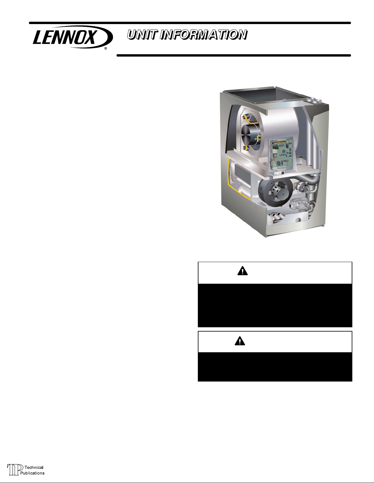
EL296DFV(X) series units are 90% efficiency gas furnaces
used for upflow or horizontal applications only, manufac
tured with Lennox Duralok heat exchangers formed of
aluminized steel. EL296DFV(X) units are available in heat
ing capacities of 44,000 to 110,000 Btuh and cooling ap
plications up to 5 tons. Refer to Engineering Handbook for
proper sizing.
Units are factory equipped for use with natural gas. Kits are
available for conversion to LPG operation. EL296DFV(X)
model units are equipped with the icomfort
®
eLight
EL296DFV(X) unit meets the California Nitrogen Oxides
(NO
quirements. All units use a redundant gas valve to assure
safety shut-off as required by C.S.A.
All specifications in this manual are subject to change. Pro
cedures outlined in this manual are presented as a recom
mendation only and do not supersede or replace local or
state codes. In the absence of local or state codes, the
guidelines and procedures outlined in this manual (except
where noted) are recommendations only and do not consti
tute code.
Specifications Page 2.............................
I Unit Components Page 5........................
II Installation Page 31.............................
III Start Up Page 55..............................
IV Heating System Service Checks Page 56.........
V Typical Operating Characteristics Page 59.........
VI Maintenance Page 59..........................
VII Wiring and Sequence of Operation Page 62......
VIII Field Wiring and Jumper Settings Page 67.......
IX Program Unit Capacity Size Mode Page 71.......
X Troubleshooting Page 72........................
two-stage variable speed integrated control.
) Standards and California Seasonal Efficiency re
x
TABLE OF CONTENTS
®
- ENABLED EL296DFV(X) SERIES UNITS
®
enabled Sur
WARNING
Improper installation, adjustment, alteration, service
or maintenance can cause property damage, person
al injury or loss of life. Installation and service must
be performed by a licensed professional HVAC in
staller (or equivalent), service agency or the gas sup
plier.
CAUTION
As with any mechanical equipment, contact with
sharp sheet metal edges can result in personal in
jury. Take care while handling this equipment and
wear gloves and protective clothing.
Page 1
© 2018 Lennox Industries Inc.
Page 2
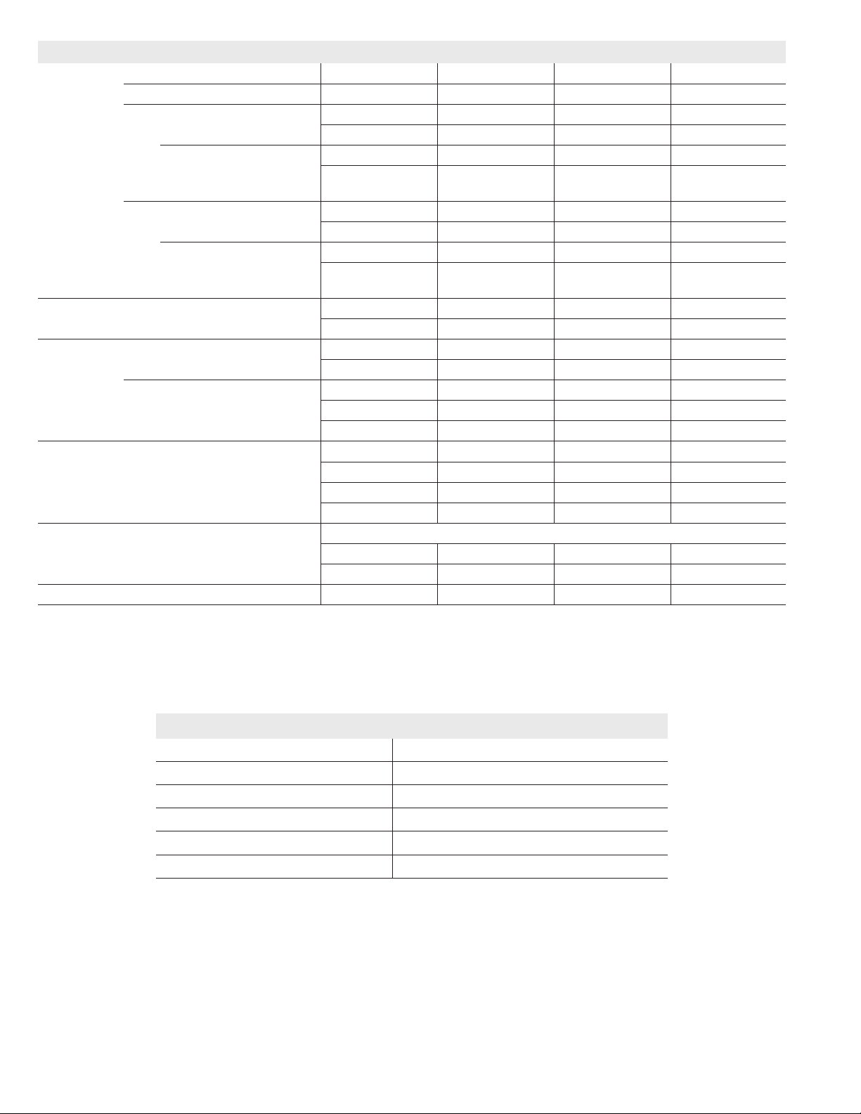
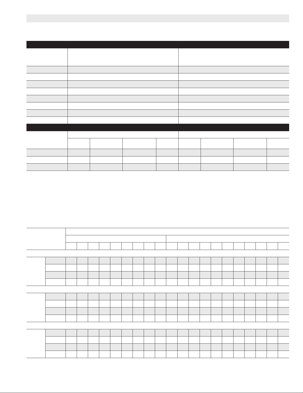
SPECIFICATIONS
Gas
Heating
Performance
High
Fire
Temperature rise range - °F 35-65 35-65 40-70 45-75
Gas Manifold Pressure (in. w.g.)
Nat. Gas / LPG/Propane
Low
Fire
Temperature rise range - °F 20 - 50 25 - 55 30 - 60 35 - 65
Gas Manifold Pressure (in. w.g.)
Nat. Gas / LPG/Propane
High static in. w.g.
Connections
in.
Intake / Exhaust Pipe (PVC) 2 / 2 2 / 2 2 / 2 2 / 2
Gas pipe size IPS 1/2 1/2 1/2 1/2
Condensate Drain Trap (PVC pipe) - i.d. 1/2 1/2 1/2 1/2
with furnished 90° street elbow 1/2 slip x 1/2 Mipt 1/2 slip x 1/2 Mipt 1/2 slip x 1/2 Mipt 1/2 slip x 1/2 Mipt
with eld supplied (PVC coupling) - o.d. 1/2 slip x 1/2 NPT 1/2 slip x 1/2 NPT 1/2 slip x 1/2 NPT 1/2 slip x 1/2 NPT
Indoor
Wheel nom. diameter x width - in. 10 x 9 11 x 10 11 x 11 11 x 11
Blower
Tons of add-on cooling 2 - 3 2.5 - 4 3 - 5 3 - 5
Air Volume Range - cfm 545 - 1360 575 - 1800 890 - 2130 860 - 2180
Electrical
Data
Blower motor full load amps 7.7
Maximum overcurrent protection 15 20 20 20
Shipping Data lbs. - 1 package 131 136 164 176
1
Annual Fuel Utilization Efciency based on DOE test procedures and according to FTC labeling regulations. Isolated combustion system rating for non-weatherized
Model No. EL296DF045XV36B EL296DF070XV48B EL296DF090XV60C EL296DF110XV60C
1
AFUE 96% 96% 96% 96%
Input - Btuh 44,000 66,000 88,000 110,000
Output - Btuh 43,000 64,000 85,000 106,000
3.5 / 10.0 3.5 / 10.0 3.5 / 10.0 3.5 / 10.0
Input - Btuh 29,000 43,000 57,000 72,000
Output - Btuh 28,000 42,000 56,000 70,000
1.7 / 4.9 1.7 / 4.9 1.7 / 4.9 1.7 / 4.9
Heating 0.8 0.8 0.8 0.8
Cooling 1.0 1.0 1.0 1.0
Motor output - hp 1/2 3/4 1 1
Voltage 120 volts - 60 hertz - 1 phase
10.1 12.8 12.8
NOTE - Filters and provisions for mounting are not furnished and must be eld provided.
furnaces.
INSTALLATION CLEARANCES
Sides
Rear 0 inches (0 mm)
Top/Plenum 1 inch (25 mm)
Front 0 inches (0 mm)
Front (service/alcove) 24 inches (610 mm)
Floor
NOTE - Air for combustion must conform to the methods outlined in the National Fuel Gas Code (NFPA 54/ANSI-
NOTE - In the U.S. ue sizing must conform to the methods outlined in the current National Fuel Gas Code (NFPA
2
Z223.1) or the National Standard of Canada CAN/CSA-B149.1 “Natural Gas and Propane Installation
54/ANSI-Z223.1) or applicable provisions of local building codes. In Canada ue sizing must conform to
1
Clearance for installation on combustible oor if Optional Downow Combustible Flooring Base is installed be-
tween furnace and combustible oor. Not required in add-on cooling applications if installed in accordance with
local codes or National Fuel Gas Code ANSI-Z223.1 or CAN/CGA-149.1,.2. Do not install the furnace directly on
the methods outlined in National Standard of Canada CAN/CSA-B149.1.
Allow proper clearances to accommodate condensate trap and vent pipe installation.
carpeting, tile, or other combustible materials other than wood ooring.
Code”.
Page 2
1
0 inches (0 mm)
2
Combustible
Page 3
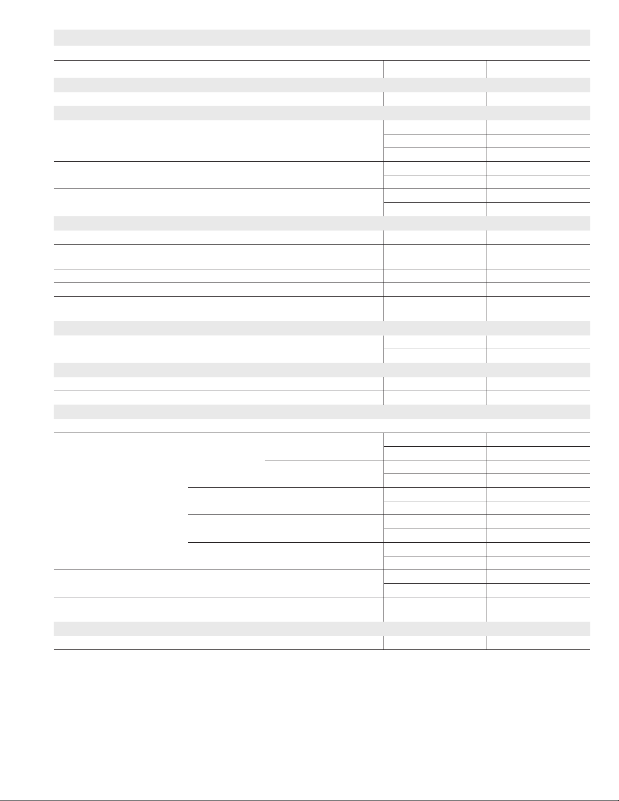
OPTIONAL ACCESSORIES - ORDER SEPARATELY
NOTE - FURNACES CANNOT BE TWINNED!
“B” Width Models “C” Width Models
CABINET ACCESSORIES
Downow Combustible Flooring Base 11M60 11M61
CONDENSATE DRAIN KITS
Condensate Drain Heat Cable 6 ft. 26K68 26K68
24 ft. 26K69 26K69
50 ft. 26K70 26K70
Heat Cable Tape Fiberglass - 1/2 in. x 66 ft. 36G53 36G53
Aluminum foil - 2 in. x 60 ft. 16P89 16P89
Crawl Space Vent Drain Kit US 51W18 51W18
Canada 51W19 51W19
CONTROLS
icomfort Touch® Communicating Thermostat 49W95 49W95
1
Remote Outdoor Temperature Sensor
(for dual fuel and Humiditrol®)
2
Discharge Temperature Sensor 88K38 88K38
®
ComfortSense
3
Remote Outdoor Temperature Sensor
7000 Thermostat Y2081 Y2081
(for dual fuel and Humiditrol)
FILTERS
4
Downow Filter Cabinet 51W07 51W08
No. and Size of lter - in. (2) 16 x 20 x 1 (2) 16 x 20 x 1
NIGHT SERVICE KITS
Night Service Kit 14C99 14C99
Universal Service Kit - Switches 89W20 89W20
TERMINATION KITS
See Installation Instructions for specic venting information.
Termination Kits Direct Vent Applications Only
Concentric US - 2 in. 71M80 69M29
3 in. - - - 60L46
Canada - 2 in. 44W92 44W92
3 in. - - - 44W93
Flush-Mount US - 2, 2-1/2 or 3 in. 51W11 51W11
Canada - 2, 2-1/2 or 3 in. 51W12 51W12
Wall - Close
Couple
Wall - Close
Couple WTK
Termination Kits Direct or Non-Direct vent
5
Roof Termination Flashing Kit - Direct or Non-Direct Vent
Wall Ring Kit 2 in. 15F74
Roof 2 in. 15F75 15F75
US - 2 in. 22G44 - - -
3 in. 44J40 44J40
Canada - 2 in. 30G28 - - -
3 in. 81J20 81J20
2 in. 44J41 44J41
(2 ashings)
VENTING
7
Left Side Vent Kit 2 or 3 in. 87W73 87W73
1
Remote Outdoor Sensor may be used with an icomfort®-enabled outdoor unit for a secondary (alternate) sensor reading. Sensor may also be used with a conventional
2
3
Remote Outdoor Temperature Sensor for ComfortSense 7000 Thermostat must be connected directly to the thermostat, Do not connect it directly to the icomfort® control.
5
Kits contain enough parts for two, non-direct vent installations.
NOTE - The curved exhaust pipe furnished with the Left Side Vent Kit counts as one additional 2 in. diameter 90° elbow. When using 3 in. diameter pipe, the furnished
curved exhaust pipe and eld provided ttings to transition from 2 in. to 3 in. count as 20 feet of equivalent pipe on all units.
NOTE - Termination Kits 44W92, 44W93, 30G28, 51W12, 51W19, 81J20 are certied to ULC S636 standard for use in Canada only.
Optional for service diagnostics.
4
Cleanable polyurethane, frame-type lter.
outdoor unit.
6
Non-direct vent only.
X2658 X2658
X2658 X2658
6
15F74
Page 3
Page 4
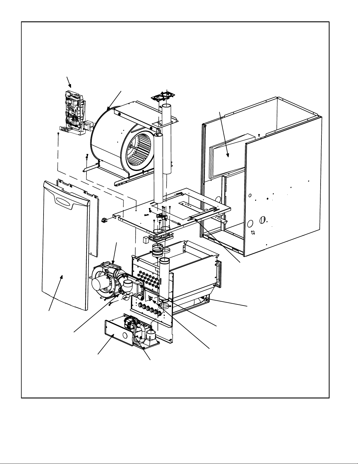
CONTROL BOX
(Includes integrated control,
transformer and door switch)
EL296DFV PARTS IDENTIFICATION
VARIABLE SPEED MOTOR
(hidden)
BAG ASSEMBLY
(shipping location)
COMBUSTION
AIR INDUCER
OUTER
ACCESS
PANEL
COMBUSTION AIR INDUCER
PRESSURE SWITCH
BURNER BOX ASSEMBLY
(includes sensor, rollout switches and ignitor)
GAS VALVE
FIGURE 1
COLD END HEADER BOX
PRIMARY LIMIT
BLOWER DECK
DuralokPlus
HEAT EXCHANGER
ASSEMBLY
TM
Page 4
Page 5
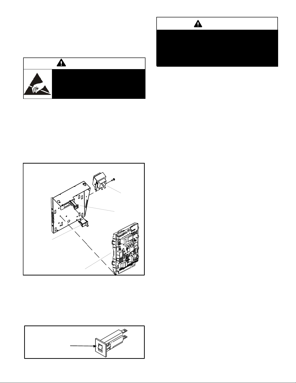
I-UNIT COMPONENTS
EL296DFV(X) unit components are shown in figure 1. The
gas valve, combustion air inducer and burners can be ac
cessed by removing the access panel. Electrical compo
nents are in the control box (figure 2) found in the blower
section.
CAUTION
Electrostatic discharge can affect elec
tronic components. Take precautions
to neutralize electrostatic charge by
touching your hand and tools to metal
prior to handling the control.
A- Control Box
1. Control Transformer (T1)
A transformer located in the control box provides power to
the low voltage section of the unit. Transformers on all
models are rated 40VA with a 120V primary and a 24V sec
ondary.
2. Door Interlock Switch (S51)
A door interlock switch rated 14A at 125VAC is wired in se
ries with line voltage. When the inner blower access panel
is removed the unit will shut down.
CONTROL BOX EL296DFV
Transformer
Circuit Breaker
Interlock Switch
SureLight
3. Circuit Breaker (CB8)
A 24V circuit breaker is also located in the control box.
The switch provides overcurrent protection to the trans
former (T1). The breaker is rated 3A at 32V. If the current
exceeds this limit the breaker will trip and all unit opera
tion will shutdown. The breaker can be manually reset
by pressing the button on the face. See figure 3.
®
Integrated Control
FIGURE 2
CIRCUIT BREAKER CB8
PRESS TO RESET
FIGURE 3
WARNING
Shock hazard.
Disconnect power before servicing. Integrated
control is not field repairable. If control is inoper
able, simply replace entire control.
Can cause injury or death. Unsafe operation will re
sult if repair is attempted.
4. Integrated Control (A92)
Units are equipped with the icomfort
two-stage, variable speed integrated control. This control
is used with the icomfort Touch® thermostat as part of a
communicating comfort system. The control can also oper
ate with a non-communicating conventional single or twostage thermostat. The system consists of a ignition / blow
er control (figures 4 and 5) with control pin designations in
tables 1, 2 and 3 and ignitor (figure 13). The control and
ignitor work in combination to ensure furnace ignition and
ignitor durability. The control provides gas ignition, safety
checks and indoor blower control with two-stage gas heat
ing. The furnace combustion air inducer, gas valve and in
door blower are controlled in response to various system
inputs such as thermostat signal, pressure and limit switch
signal and flame signal. The control features a seven-seg
ment LED display, indicating furnace status (including in
door blower) and error codes. The LED flashes in single
digits. For example using table 5 under LIMIT CODE, an
“E” followed by “2” followed by “5” followed by “0”, the limit
switch circuit is open. The control also has two unpowered
(dry) 1/4” contacts for a humidifier and a 120 volt accessory
terminal. Both rated at (1) one amp each.
Electronic Ignition
At the beginning of the heat cycle the integrated control
monitors the first stage and second stage combustion air
inducer prove switch. The control will not begin the heating
cycle if the first stage prove switch is closed (by-passed).
Likewise the integrated control will not begin the second
stage heating cycle if the second stage prove switch is
closed, and will remain in first stage heat. However, if the
second stage prove switch closes during the first stage
heat pre-purge, the control will allow second stage heat.
Once the first stage prove switch is determined to be open,
the combustion air inducer is energized on low (first stage)
heat speed. When the differential in the prove switch is
great enough, the prove switch closes and a 15-second
pre-purge begins.
NOTE - During abnormal conditions such as low supply
voltage or low outdoor temperatures and the low fire pres
sure switch does not close, the combustion air inducer will
switch to high fire. After a 15 second pre-purge the high fire
pressure switch will close and the unit will begin operation
on high fire. After 10 to 20 seconds of high fire operation the
unit will switch to low fire
After the 15-second pre-purge period, the SureLight ignitor
warms up for 20 seconds after which the gas valve opens
for a 4-second trial for ignition. The ignitor remains ener
gized during the trial until flame is sensed. If ignition is not
®
enabled SureLight
®
Page 5
Page 6
proved during the 4-second period, the control will try four
more times with an inter purge and warm-up time between
trials of 35 seconds. After a total of five trials for ignition (in
cluding the initial trial), the control goes into WatchguardFlame Failure mode. After a 60-minute reset period, the
control will begin the ignition sequence again.
Two Stage Operation / Thermostat Selection DIP
Switch
The control can be utilized in two modes: SINGLE-STAGE
thermostat or TWO-STAGE thermostat. The thermostat
selection is made using a DIP switch and must be posi
tioned for the particular application. DIP switch 1, labeled
T”STAT HEAT STAGE is factory-set in the OFF position for
use with a two-stage thermostat. Move the DIP switch to
ON for use with a single stage thermostat.
While in the single-stage thermostat mode, the burners will
always fire on first-stage heat. The combustion air inducer
will operate on low speed and indoor blower will operate on
low heat speed. The unit will switch to second stage heat
after a "recognition period". DIP switch 2, labeled SECOND
STAGE DELAY, is factory set in the OFF position for a 7
minute recognition period. The switch can be moved to the
ON position for a 12 minute recognition period, after which
time the unit will switch to secondstage heat. While in the
two-stage thermostat mode, the burners will fire on firststage heat. The combustion air inducer will operate on low
speed and indoor blower will operate on low heat speed.
The unit will switch to second-stage heat on call from the
indoor thermostat. If there is a simultaneous call for first
and second stage heat, the unit will fire an first stage heat
and switch to second stage heat after 30 seconds of opera
tion. See Sequence of Operation flow charts in the back of
this manual for more detail.
TABLE 1
®
SureLight
PIN # Function
Control 5 Pin Terminal Designation
1 Ignitor
2 Combustion Air Inducer High Speed
3 Combustion Air Inducer Low Speed
4 Combustion Air Inducer Neutral
5 Ignitor Neutral
TABLE 2
®
SureLight
Control 12 Pin Terminal Designation
PIN # Function
1 Gas Valve Second Stage
2 Second Stage Prove Switch
3 Rollout Switch In
4 Ground
5 24V Hot
6 Primary Limit In
7 Gas Valve First Stage
8 Gas Valve Common
9 24V Neutral
10 Ground
11 Rollout Switch Out
12 First Stage Prove Switch
TABLE 3
®
Control 6 Pin Terminal Designation
SureLight
PIN # Function
1 Data Input From Motor
2 Common
3 Not Used
4 Data Output To Motor
5 5 Volt Bias Supply
6 Not Used
Page 6
Page 7
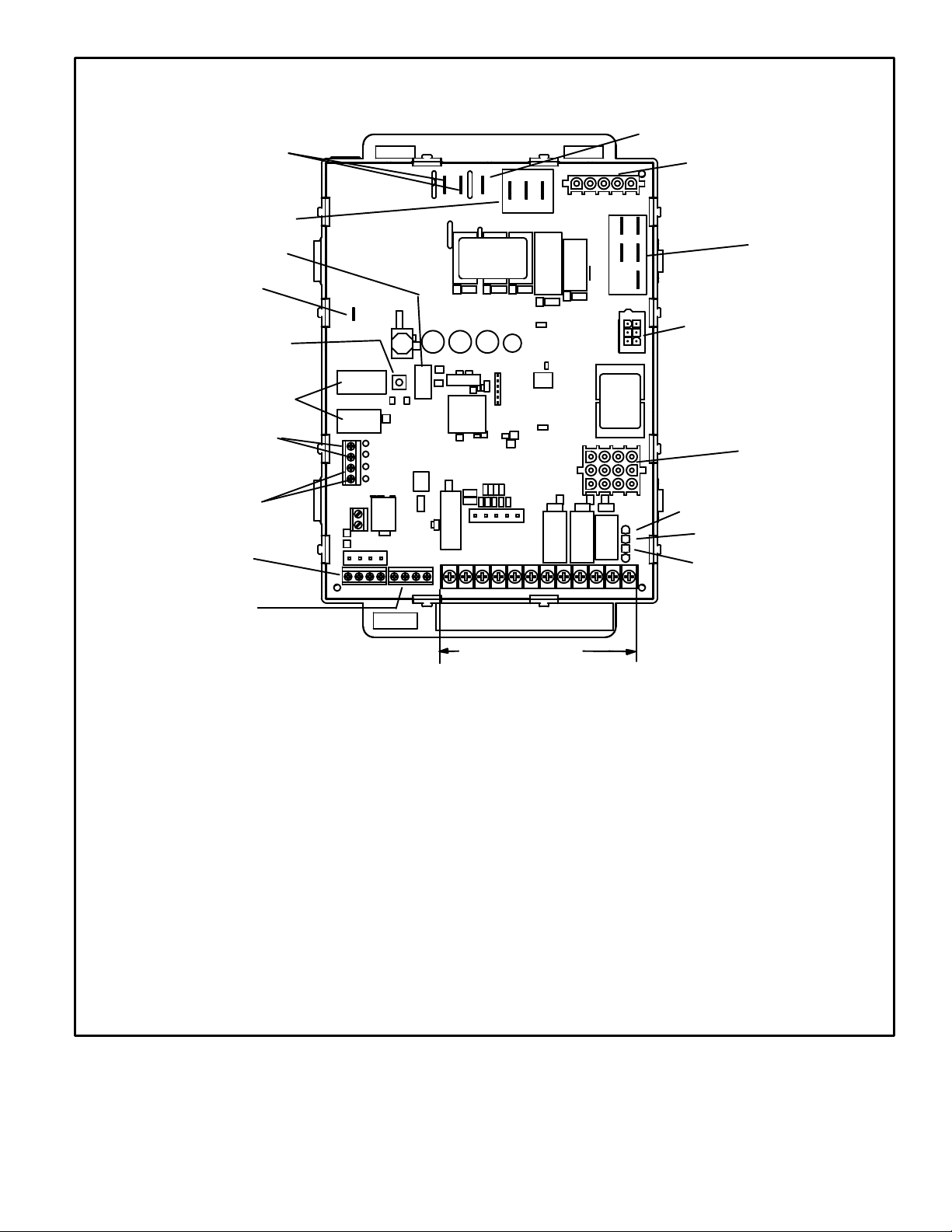
HUM
LINE 1
7 SEGMENT LED
FLAME SENSE
DIAGNOSTIC
PUSH BUTTON
DIP SWITCHES
INTEGRATED CONTROL
ACC
HS/ CAI
INDOOR
BLOWER
CONNECTOR
NEUTRAL
OUTDOOR AIR
SENSOR
TERMINALS
DISCHARGE AIR
SENSOR
TERMINALS
TB83
icomfort
COMMUNICATING
OUTDOOR
EQUIPMENT
TB84
icomfort
COMMUNICATING
INDOOR
THERMOSTAT
I + I -CRI + I -
R
TB83 icomfort Communicating Outdoor Equipment
R = 24VAC
I + = DATA HIGH CONNECTION
I - = DATA LOW CONNECTION
C = 24VAXC COMMON
TB84 icomfort Communicating Indoor Thermostat
R = 24VAC
I + = DATA HIGH CONNECTION
I - = DATA LOW CONNECTION
C = 24VAXC COMMON
1/4” QUICK CONNECT TERMINALS
HUM = UNPOWERED NORMALLY OPEN (DRY) CONTACTS
XMFR = 120 VAC OUTPUT TO TRANSFORMER
LI = 120 VAC INPUT TO CONTROL
ACC = 120 VAC OUTPUT TO OPTIONAL ACCESSORY
NEUTRALS = 120 VAC NEUTRAL
C
W1 W2 GY2Y1
NON-COMMUNICATING
24V TERMINALS
12 PIN LOW
VOLTAGE
CONNECTOR
W915 Y1 TO Y2
2 STAGE COMPR
W951 R TO O
HEAT PUMP
W914 R TO DS
DEHUM OR
CC
RDHLODS
HARMONY
THERMOSTAT CONNECTIONS (TB1)
DS = DEHUMIDIFICATION SIGNAL
W2 = HEAT DEMAND FROM 2ND STAGE T/STAT
W1 = HEAT DEMAND FROM 1ST STAGE T/STAT
R = CLASS 2 VOLTAGE TO THERMOSTAT
G = MANUAL FAN FROM T'STAT
C = THERMOSTAT SIGNAL GROUND CONNECTED TO
TRANSFORMER GRD (TR) & CHASIS GROUND (GRD)
Y1 = THERMOSTAT 1ST STAGE COOL SIGNAL
Y2 = THERMOSTAT 2ND STAGE COOL SIGNAL
O = THERMOSTAT SIGNAL TO HEAT PUMP
DH = DEHUMIDIFICATION OUTPUT COMMUNICATING
L = USE ONLY WITH A COMMUNICATING THERMOSTAT
AND A NON-COMMUNICATING OUTDOOR UNIT
REVERSING VALVE
THERMOSTAT ONLY
FIGURE 4
Page 7
Page 8
THERMOSTAT SELECTION
1
2
3
*
TWO STAGE
THERMOSTAT
1−STAGE
THERMOSTAT
(TIMED STAGING)
−SEE SW #2
HEATING BLOWER−OFF DELAY
*
90 SECOND
HTG BLOWER
OFF DELAY
60 SECOND
HTG BLOWER
OFF DELAY
120 SECOND
HTG BLOWER
OFF DELAY
180 SECOND
HTG BLOWER
OFF DELAY
−BLOWER ON DELAY − 30 SEC. FIXED
4
ON
1
2
3
4
ON
1
2
3
4
ON
1
2
3
4
ON
1
2
3
4
ON
1
2
3
4
ON
HEATING MODE BLOWER SPEED
9
11
10
+ 24%
+ 18%
+ 12%
INCREASE AIR HTG CFM
+ 6%
*
FACTORY
DEFAULT
− 6%
− 12%
DECREASE AIR HTG CFM
− 18%
ON
9
11
10
ON
9
11
10
ON
9
11
10
ON
9
11
10
ON
9
11
10
ON
9
11
10
ON
9
11
10
ON
5
6
7
5
6
7
5
6
7
5
6
7
5
6
7
5
6
7
13
12
13
12
13
12
13
12
13
12
13
12
13
12
13
121415
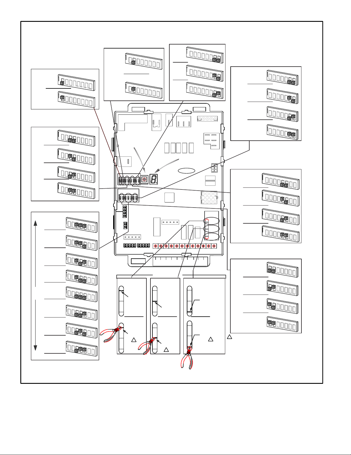
INTEGRATED CONTROL CONFIGURATION GUIDE
2ND STAGE HEAT ON DELAY
1
2
3
4
5
2
3
4
S1
7
8
15
14
INDOOR EQUIPMENT
1
6
5
6
HEAT PUMP LINK
(JUMPERS R to O)
7 MIN
UPSTAGE
DELAY
12 MIN
UPSTAGE
DELAY
FLAME
SENSE
123456
ON
S4S3
911
ON
OUTDOOR
SENSOR
DISCHARGE
AIR SENSOR
I+ I−
OUTDOOR EQUIPMENT
ON
1
ON
DIAGNOSTIC
PUSH BUTTON
13
10
12
RI+ I− CRI+ I− C
*
8
8
8
8
8
8
15
14
15
14
15
14
15
14
1−STG COMPRESSOR
15
14
W915
2 STAGE
COMPR
DO NOT CUT
15
14
2−STG COMPRESSOR
15
14
W915
2 STAGE
COMPR
CUT LINK
2−STAGE
COMPRESSOR LINK
(JUMPERS Y1 to Y2)
W915
CLG BLOWER SPEED ADJUSTMENT
*
7
7
HUM
W1W2 G Y2 Y1 C C DH L O DSR
HEAT PUMP UNIT
DEFAULT
8
8
ACC
W1
W2GY2
ON−BOARD LINK
OPTION SELECTION
A/C UNIT
W951
HEAT
PUMP
DO NOT CUT
W951
HEAT
PUMP
CUT LINK
1
W951
ON
ON
+ 10%
ON
− 10%
L1
DIAGNOSTIC
LED
SureLight
C
C
Y1
1
2
3
4
1
2
3
4
1
2
3
4
HSI/CAI
1
J3
IGN
CAI2
®
110
4 7
3
SELECTION
L
R
DH
NO HARMONY ZONING
OR
NO SIGNATURESTAT
W/ DS CONNECTION
DO NOT CUT
W914
DEHUM
or
HARMONY
HARMONY ZONING
SIGNATURESTAT W/
DS CONNECTION
CUT LINK
W914
DEHUM
or
HARMONY
DEHUMIDIFICATION−
HARMONY LINK
(JUMPERS R to DS)
5
6
5
6
5
6
N
CAI1
14
3
CUT FOR
OPTION
W915
2 STAGE
COMPR
W951
HEAT
PUMP
W914
DEHUM
HARMONY
OR
1
W914
7
7
7
5
N
P79
6
12
8
CONTINUOUS FAN MODE BLOWER SPEED
8
8
NEUTRALS
MEDIUM−LOW
*
SPEED
(38%)
MEDIUM−HIGH
SPEED
(70%)
LOW
SPEED
(28%)
HIGH
SPEED
(100%)
9
11
10
ON
9
11
10
ON
9
11
10
ON
9
11
10
ON
COOLING MODE BLOWER SPEED
1
2
3
*
HIGH
SPEED
MEDIUM−HIGH
J2
SPEED
MEDIUM−LOW
SPEED
LOW
SPEED
COOLING MODE BLOWER RAMPING
*
OPTION A
OFF−50%−82%−
100%−50%−OFF
OPTION B
OFF−82%−100%−OFF
OPTION C
OFF−100%−100%−OFF
OPTION D
OFF−100%−OFF
−CUT ON−BOARD LINK (SOLDER TRACE) COMPLETELY THROUGH
1
BOTH LAYERS ON THE CONTROL BOARD
−LINKS CUT IN ERROR −INSTALL A JUMPER ON THE APPROPRIATE
TERMINALS ON THE TERMINAL STRIP
−PROTECTIVE PLASTIC FILM ON DIP SWITCHES MAY BE
REMOVED FOR EASE IN SETTING OF DIP SW.
* FACTORY DEFAULT
ON
1
2
3
ON
1
2
3
ON
1
2
3
ON
9
11
10
ON
9
11
10
ON
9
11
10
ON
9
11
10
ON
13
15
12
14
15
12
14
15
12
14
15
12
14
4
5
6
7
8
4
5
6
7
8
4
5
6
7
8
4
5
6
7
8
13
15
12
14
13
15
12
14
13
15
12
14
13
15
12
14
FIGURE 5
Page 8
Page 9

TABLE 4
Integrated Control Diagnostic Modes
Display Action (when button released)
No change (idle)* Remain in idle mode
Solid “E” Enter diagnostic recall mode
Solid “F” Enter flame signal mode
Solid “P” (variable speed only) Program unit capacity/size (Unit Code)
__
Two horizontal bars __
Soft disable
* No change implies the display will continue to show whatever is currently being displayed for normal operation (blinking
decimal, active error code, heat state, etc..)
Diagnostic LED (Figure 4)
The seven-segment diagnostic LED displays operating
status, target airflow, error codes and other information.
The table beginning on Page 10 lists diagnostic LED
codes.
Diagnostic Push Button (Figure 4)
The diagnostic push button is located adjacent to the
seven-segment diagnostic LED. This button is used to en
able the Error Code Recall “E” mode, the Flame Signal “F”
mode and “P” the Program Unit Capacity/Size mode. Press
the button and hold it to cycle through a menu of options.
Every five seconds a new menu item will be displayed.
When the button is released, the displayed item will be se
lected. Once all items in the menu have been displayed, the
menu resumes from the beginning until the button is re
Program Unit Capacity/Size Mode
After the “P” is selected (by releasing the push button) the
integrated control will start flashing the “P” on display for 90
seconds. If push button is pressed again and held during
that time, the control will start to display characters corre
sponding to different variable speed furnace models for 3
seconds each. While the wanted character-model is dis
played push button has to be released. Selected option will
flash display for 10 seconds and during that time push but
ton has to be pressed and held for 5 seconds. Once control
accepts new setting it will store data in non-volatile memory
and reset itself. If 10 seconds expires or push button is held
less than 5 seconds, control will exit field test mode and go
into idle without changing programming the unit size.
leased.
Error Code Recall Mode
Select ”E” from the menu to access the most recent 10 error
codes. Select “c” from the Error Code Recall menu to clear
all error codes. Button must be pressed a second time
while “c” is flashing to confirm command to delete codes.
Press the button until a solid “≡” is displayed to exit the Error
Code Recall mode.
Flame Signal Mode
Select ”F” from the menu to access the flame signal mode.
The integrated control will display the flame current on
seven-segment LED in in micro amps (uA).
Soft Disable
Soft disabling is when thermostat finds a device on the BUS
that it does not recognize and the thermostat sends a the
device a message to be in soft disabling mode until proper
ly configured. Two horizontal bars will display.
Steps to follow if the damper control module is displaying
the soft disable code.
1- Confirm proper wiring between all devices (thermo
stat, damper control module, indoor and outdoor).
2- Cycle power to the control that is displaying the soft
disable code.
Flame signal mode is exited after any of the following:
Power is reset
Pressing and holding push button until 3 horizontal
lines “≡” are displayed
10 minutes after entering the flame sense mode.
3- Put the room thermostat through set up.
4- Go to setup / system devices / thermostat / edit /
then push reset.
5- Go to setup / system devices / thermostat / edit /
then push resetAll.
Page 9
Page 10
TABLE 5
Integrated Diagnostic Codes/Status of Equipment
Code Diagnostic Codes/Status of Equipment Action Required to Clear and Recover
.
Idle mode (Decimal blinks at 1 Hertz -- 0.5 second ON, 0.5 second OFF).
A
Cubic feet per minute (cfm) setting for indoor blower (1 second ON, 0.5
second OFF) / cfm setting for current mode displayed.
C
Cooling stage (1 second ON, 0.5 second OFF) / 1 or 2 displayed / Pause
/ cfm setting displayed / Pause / Repeat codes).
d
Dehumidification mode (1 second ON) / 1 second OFF) / cfm setting dis
played / Pause / Repeat Codes).
h
Heat pump stage (1 second ON, 0.5 second OFF) / % of input rate dis
played / Pause / cfm setting / Pause / Repeat codes.
H
Gas Heat Stage (1 second ON, 0.5 second OFF) / 1 or 2 displayed /
Pause / cfm
setting displayed / Pause / Repeat codes. Blinking during ignition.
dF
Defrost mode.
U
Discharge Air Temperature
E 105
Device communication problem - No other devices on RS BUS (Commu
nication
system).
E 110
Low line voltage. Line Voltage Low (Voltage lower than nameplate
E 111
Line voltage polarity reversed. Reverse line power voltage wiring. System resumes
E 112
Ground not detected System shuts down. Provide proper earth ground.
E 113
High line voltage. Line Voltage High (Voltage higher than nameplate
E 114
Line voltage frequency out-of-range. No 60 Hertz Power. Check voltage and line power
E 115
Low 24V - Control will restart if the error recovers. 24-Volt Power Low (Range is 18 to 30 volts). Check
E 116
High 24V. 24 Volt Power High (Range is 18 to 30 volts). Check
E 117
Poor ground detected (Warning only) Provide proper grounding for unit. Check for proper
E 120
Unresponsive device. Communication only. Usually caused by delay in outdoor unit responding
Equipment is unable to communicate. Indicates
numerous message errors. In most cases errors are
related to electrical noise. Make sure high voltage
power is separated from RSBus. Check for miswired and/or loose connections between the stat,
indoor unit and outdoor unit. Check for a high volt
age source of noise close to the system. Fault
clears after communication is restored.
rating). Check power line voltage and correct. Alarm
clears 5 seconds after fault recovered.
normal operation 5 seconds after fault recovered.
System resumes normal operation 5 seconds after
fault recovered.
rating). Provide power voltage within proper range.
System resumes normal operation 5 seconds after
fault recovered.
frequency. Correct voltage and frequency problems.
System resumes normal operation 5 seconds after
fault recovered.
and correct voltage. Check for additional power-rob
bing equipment connected to system. May require
installation of larger VA transformer to be installed
in furnace / air handler. Clears after fault recovered.
and correct voltage. Check for proper line voltage
(120V, 240V, etc.) to equipment. Clears when con
trol senses proper voltage.
earth ground to the system. Warning only will clear
30 seconds after fault recovered.
to indoor unit poling. Recycle power. Check all wir
ing connections. Cleared after unresponsive device
responds to any inquiry.
Page 10
Page 11
TABLE 5 Continued
Code Diagnostic Codes/Status of Equipment Action Required to Clear and Recover
E 124
Active communicating thermostat signal missing for more than 3 min
utes.
E 125
Control failed self-check, internal error, failed hardware. Will restart if
error
recovers. Integrated control not communicating. Covers hardware errors
(flame sense circuit faults, pin shorts, etc.).
E 126
Control internal communication problem. Hardware problem on the control. Cycle power on
E 131
Corrupted control parameters (Verify configuration of system). Communi
cating only.
E 180
Outdoor air temperature sensor failure. Only shown if shorted or out-ofrange.
E 200
Hard lockout - Rollout circuit open or previously open. Correct cause of rollout trip, or replace flame rollout
E 201
Indoor blower communication failure - Unable to communicate with blow
er motor.
E 202
Indoor blower motor mis-match - Indoor motor horsepower does not
match unit capacity. See Page 71.
E 203
Appliance capacity / size is NOT programmed. Invalid unit codes refer to
configuration flow chart. See Page 71.
E 204
Gas valve mis-wired. Check gas valve operation and wiring. Clears when
E 205
Gas valve control relay contact shorted. Check wiring on control and gas valve. If wiring is
Equipment lost communication with the thermostat.
Check four wiring connections, ohm wires and cycle
power at the thermostat. Alert stops all services and
waits for heartbeat message from thermostat (sub
net controller). Cleared after valid thermostat (sub
net controller) message is received.
Hardware problem on the control. Cycle power on
control. Replace if problem prevents service and is
persistent. Critical alert. Cleared 300 seconds after
fault recovered.
control. Replace if problem prevents service and is
persistent. Cleared 300 seconds after fault recov
ered.
Reconfigure the system. Replace control if heating
or cooling is not available. Only applicable in the
communicating mode, not in startup. Exit from Com
missioning and Execute 'Set Factory Default mode'.
Control will still operate on default parameter set
tings.
Compare outdoor sensor resistance to temperature/
resistance charts in unit installation instructions.
Replace sensor pack if necessary. At beginning of
(any) configuration, furnace or air handler control
will sense outdoor air and discharge air temperature
sensor(s). If detected (reading in range), appropri
ate feature will be set as 'installed' and that could be
seen in 'About' screen. In normal operation after
control recognizes sensors, alarm will be sent if
valid temperature reading is lost. To get rid of set
ting and alarm, redo configuration and make sure
that temperature sensor is marked as 'not installed'
in Indoor Unit 'About' screen. When Indoor unit con
trol is replaced, thermostat will 'tell' new control if
temperature sensor is in system or not. Clears 30
seconds after fault recovered.
switch. Test furnace operation. Cleared after fault
recovered.
Indoor blower communication failure (including pow
er outage). Lost communication with indoor blower
motor. Possible causes: motor not powered, loose
wiring. Problem may be on control or motor side.
Cleared after fault recovered.
Incorrect appliance capacity code selected. Check
for proper configuring under: Unit Size Codes for
Furnace/Air Handler on configuration guide or in
installation instructions. Cleared after the correct
match is detected following a reset. (Remove ther
mostat from system while applying power and re
programming.)
No appliance capacity code selected. Check for
proper configuring under: Unit Size Codes for Fur
nace on configuration guide or in installation instruc
tions. Critical Alert. Cleared after valid unit code is
read following a reset. (Remove thermostat from
system while applying power and reprogramming.)
repaired.
correct, replace control.
Page 11
Page 12
TABLE 5 Continued
Code Diagnostic Codes/Status of Equipment Action Required to Clear and Recover
E 206
Gas valve second-stage relay failure Furnace will operate on 1st stage for remainder of
the heating demand. Will clear after fault recovered.
If unable to operate 2nd stage, replace control.
E 207
Hot surface ignitor sensed open - Refer to troubleshooting. See Page 72. Measure resistance of hot surface ignitor. Replace if
open or not within specified range found in IOM.
Resumes normal operation after fault is cleared.
E 223
Low pressure switch failed open. Check pressure (inches w.c.) of low pressure switch
closing on heat call. Measure operating pressure
(inches w.c.). Inspect vent and combustion air in
ducer for correct operation and restriction. Re
sumes normal operation after fault is cleared
E 224
Low pressure switch failed closed - Refer to troubleshooting. See
Page 72.
E 225
High pressure switch failed open - Refer to troubleshooting. See
Page 72.
E 226
High pressure switch failed closed - Refer to troubleshooting. See
Page 72.
E 227
Low pressure switch open during trial for ignition or run mode. Refer to
troubleshooting. See Page 72.
E 228
Combustion air inducer calibration failure Unable to perform pressure switch calibration.
E 229
Ignition on High Fire - Information Only Code is displayed if 1) low pressure switch fails to
E 240
Low flame current - Run mode - Refer to troubleshooting. See Page 72. Check micro-amperes of flame sensor using control
E 241
Flame sensed out of sequence - Flame still present. Shut off gas. Check for gas valve leak. Replace, if
E 250
Limit switch circuit open - Refer to troubleshooting. See Page 72 Check for proper firing rate on furnace. Ensure
E 252
Discharge air temperature too high (gas heat only). Check temperature rise, air flow and input rate.
E 270
Soft lockout - Exceeded maximum number of retries. No flame current
sensed.
Check operation of low pressure switch to see if it is
stuck closed on heat call longer than 150 seconds.
Measure operating pressure (inches w.c.). Inspect
vent and combustion air inducer for correct opera
tion and restriction. Resumes normal operation after
fault is cleared.
Check pressure (inches w.c.) of high pressure
switch closing on heat call. Measure operating pres
sure (inches w.c.). Inspect vent and combustion air
inducer for correct operation and restriction. Re
sumes normal operation after fault is cleared.
Check operation of high pressure switch closing on
heat call. Measure operating pressure (inches w.c.).
Inspect vent and combustion air inducer for correct
operation and restriction. Resumes normal opera
tion after fault is cleared.
Check pressure (inches w.c.) of low pressure switch
closing on heat call. Measure operating pressure
(inches w.c.). Inspect vent and combustion air in
ducer for correct operation and restriction. Re
sumes normal operation after fault is cleared.
Check vent system and pressure switch wiring con
nections. Resumes normal operation after fault is
cleared.
close, then furnace will switch to high speed inducer
to close both low and high pressure switches, then
furnace lights on high fire, or 2) if continuous fan is
active, furnace lights on high fire for 60 seconds to
improve heat exchanger warm up time.
diagnostics or field-installed mode. Clean or replace
sensor. Measure voltage of neutral to ground to
ensure good unit ground. Alert clears after current
heat call has been completed.
necessary. Alert clears when fault is recovered.
there is no blockage in heater. Check for proper air
flow. If limit not closed within 3 minutes, unit will go
into 1-hour soft lockout. Resumes normal operation
after fault is cleared.
Cleared when heat call is finished.
Check for proper gas flow. Ensure that ignitor is
lighting burner. Check flame sensor current. Clears
when heat call finishes successfully.
Page 12
Page 13
TABLE 5 Continued
Code Diagnostic Codes/Status of Equipment Action Required to Clear and Recover
E 271
Soft lockout - Exceeded maximum number of retries. Last retry failed due
to the pressure switch opening.
E 272
Soft lockout - Exceeded maximum number of recycles. Last recycle due
to the pressure switch opening.
E 273
Soft lockout - Exceeded maximum number of recycles. Last recycle due
to flame failure.
E 274
Soft lockout - Exceeded maximum number of recycles. Last recycle
failed due to the limit circuit opening or limit remained open longer than
3 minutes.
E 275
Soft lockout - Flame sensed out of sequence. Flame signal is gone. Shut off gas. Check for gas valve leak. 1-hour soft
E 276
Watchguard calibration failure. Unable to perform pressure switch calibration.
E 290
Ignitor circuit fault - Failed ignitor or triggering circuitry. Measure resistance of hot surface ignitor. Replace if
E 291
Heat air flow restricted below the minimum. Check for dirty filter and air flow restriction. Check
E 292
Indoor blower motor unable to start due to obstructed wheel, seized
bearings.
E 294
Combustion air inducer over current. Check combustion blower bearings, wiring and
E 295
Indoor blower motor temperature is too high. Indoor blower motor over temperature (motor
E 310
Discharge error temperature sensor failure. Only shown if shorted or
out of range.
E 311
Heat rate reduced to match indoor blower air flow. Warning Only. Furnace blower in cutback mode due
Check pressure (inches w.c.) of low pressure switch
closing on heat call. Measure operating pressure
(inches w.c.). Inspect vent and combustion air in
ducer for correct operation and restriction. Clears
when heat call finishes successfully.
Check operation of low pressure switch to see if it is
stuck closed on heat call. Check pressure (inches
w.c.) of high pressure switch closing on heat call.
Measure operating pressure (inches w.c.). Inspect
vent and combustion air inducer for correct opera
tion and restriction. Clears when heat call finishes
successfully.
Check micro-amperes of flame sensor using control
diagnostics or field-installed mode. Clean or replace
sensor. Measure voltage of neutral to ground to
ensure good unit ground. Clears when heat call
finishes successfully.
Shut down system. 1-hour soft lockout. Check firing
rate and air flow. Check for blockage. Clears when
heat call finishes successfully.
lockout. Clears when flame has been proven stable.
Check vent system and pressure switch wiring con
nections. 1-hour soft lockout. Clears when calibra
tion has finished successfully.
open or not within specifications. 1-hour soft lock
out. Clears when flame has been proven stable.
blower performance. 1-hour soft lockout. Cleared
when heat call finishes successfully.
Indoor blower motor unable to start (seized bear
ing, stuck wheel, etc.). Replace motor or wheel if
assembly does not operate or meet performance
standards. 1-hour soft lockout. Clears after circula
tor successfully starts.
amps. Replace if does not operate or does not meet
performance standards. Clears after inducer current
is sensed to be in-range after the ignition following
the soft lockout or reset.
tripped on internal protector). Check motor bearings
and amps. Replace if necessary. Cleared after
blower demand is satisfied.
Compare outdoor sensor resistance to temperature/
resistance charts in installation instructions. Re
place sensor if necessary. Cleared in Communicat
ing mode: 30 seconds after fault recovered. In NonCommunicating mode: Cleared after the current
heat call is completed.
to restricted airflow. Reduce firing rate every 60
seconds to match available CFM. Check filter and
duct system. To clear, replace filter if needed or re
pair/add duct. 2-stage controls will reduce firing rate
st
stage. Clears when heat call finishes success
to 1
fully.
Page 13
Page 14
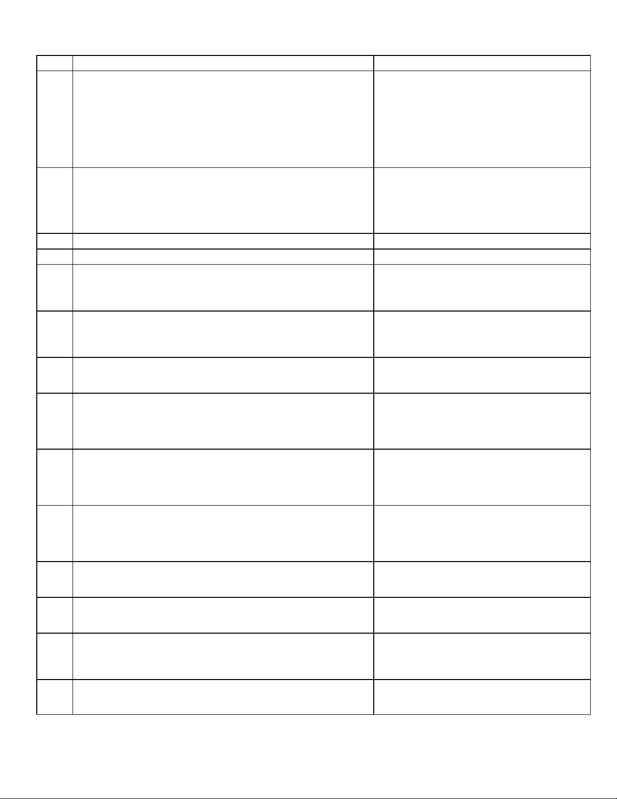
TABLE 5 Continued
Code Diagnostic Codes/Status of Equipment Action Required to Clear and Recover
E 312
E 313
E 331
E 334
E 347
E 348
E 349
E 370
E 400
E 401
E 402
E 403
E 404
E 405
Restricted air flow in cooling or continuous fan mode is lower than cfm
setting.
Indoor or outdoor unit capacity mismatch. Communication only. Incorrect indoor/outdoor capacity code selected.
Global network connection - Communication link problem. For Future Use.
Relay “Y1” stuck on interated control. Replace integrated control.
No 24 Volt output on Y1 of ”integrated control” with non communicating
outdoor unit.
No 24 Volt output on Y2 of ”integrated control” with non?communicating
outdoor unit.
No 24 Volts between R & O on ”integrated control” with non communi
cating outdoor unit (Dual fuel module required for heat pump applica
tion).
Interlock switch sensed open for 2 minutes. Control sees the loss of 24VAC for 2 minutes .Ter
LSOM - Compressor internal overload tripped. Thermostat demand Y1 is present; but, compressor
LSOM Compressor long run cycle or low system pressure. Compressor ran more than 18 hours to satisfy a
LSOM - Outdoor unit system pressure trip. Discharge or suction pressure out-of-limits, or com
LSOM - Compressor short-cycling. .(Running less than 4 minutes). Out
door unit pressure trip
LSOM - Compressor rotor locked. Compressor short-cycling. (Running
less than 4 minutes).
LSOM - Compressor open circuit. Compressor circuit open (due to power disconnec
Warning Only. Restricted airflow - Indoor blower is
running at a reduced CFM (Cutback Mode - The
variable speed motor has pre-set speed and torque
limiters to protect the motor from damage caused
by operating outside of design parameters (0 to 0.8”
W.C.. total external static pressure). Check filter
and duct system. To clear, replace filter if needed or
repair/add duct. Cleared after the current service
demand is satisfied.
Check for proper configuring in installation instruc
tions. Alarm is just a warning. The system will oper
ate, but might not meet efficiency and capacity pa
rameters. Alarm will clear when commissioning is
exited. Cleared after commissioning is complete.
Operation stopped. Y1 relay / Stage 1 failed. (Pilot
relay contacts did not close or the relay coil did not
energize; no input back to IFC chip). Critical Alert.
Cleared after reset and Y1 input sensed.
Y2 relay / Stage 2 failed. (Pilot relay contacts did
not close or the relay coil did not energize; no input
back to IFC chip). Critical Alert. Cleared after reset
and Y1 input sensed.
Configuration link R to O needs to be restored. Re
place link or hard-wire. Applicable in non communi
cating mode. Critical Alert.
minate all services and wait for interlock switch to
close. The alarm will clear when 24VAC is continu
ously sensed on DS terminal for a minimum of 10
seconds or on a power reset.
is not running. Check power to outdoor unit. Clears
the error after current is sensed in both RUN and
START sensors for at least 2 seconds, or after ser
vice is removed, or after power reset.
single thermostat demand. Critical Alert. Clears the
error after 30 consecutive normal run cycles or
power reset. Also monitors low pressure switch
trips.
pressor overloaded. Clears the error after 4 consec
utive normal compressor run cycles.
Compressor runs less than 3 minutes to satisfy a
thermostat demand. Clears the error after 4 consec
utive normal run cycles or power reset.
Compressor rotor locked up due to run capacitor
short, bearings are seized, excessive liquid refriger
ant, etc. Clears the error after 4 consecutive normal
run cycles or after power reset.
tion, open fuse, etc.) Clears the error after 1 normal
compressor run cycle.
Page 14
Page 15
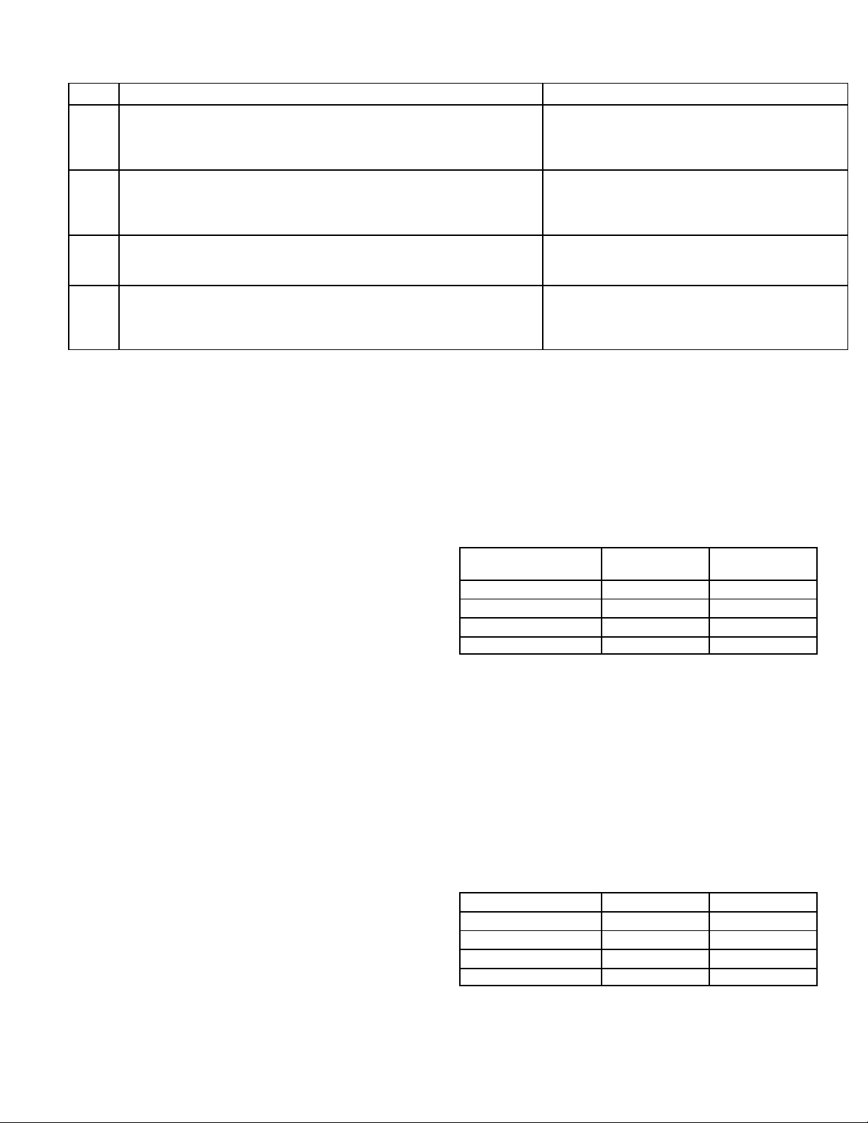
TABLE 5 Continued
Code Diagnostic Codes/Status of Equipment Action Required to Clear and Recover
E 406
E 407
E 408
E 409
LSOM - Compressor open start circuit. Required amount of current is not passing through
Start current transformer. Clears the error after cur
rent is sensed in START sensor, or after power re
set.
LSOM - Compressor open run circuit. Required amount of current is not passing through
Run current transformer. Clears the error after cur
rent is sensed in RUN sensor, or 1 normal compres
sor run cycle, or after power reset.
LSOM - Compressor contactor is welded. Compressor runs continuously. Clears the error
after 1 normal compressor run cycle or after power
reset.
LSOM - Compressor low voltage. Secondary voltage is below 18VAC. After 10 min
utes, operation is discontinued. Clears the code
after voltage is higher than 20 VAC for 2 seconds or
after power reset.
DIP Switch Settings
NOTE - All icomfortt settings are set at the icomfort Wi-Fi
thermostat. See icomfortt installation instruction. In icom
fortt communication system all DIP switch and clippable
link settings are ignored. For conventional thermostats pro
ceed with DIP switch and clippable link settings as outlined
in the following.
Heating Operation DIP Switch Settings
Switch 1 -- Thermostat Selection -- This unit may be
used with either a single-stage or two-stage thermostat.
The thermostat selection is made using a DIP switch which
must be properly positioned for the particular application.
The DIP switch is factory-positioned for use with a twostage thermostat. If a single-stage thermostat is to be used,
the DIP switch must be repositioned.
Select “OFF” for two-stage heating operation con
trolled by a two-stage heating thermostat (factory set
ting);
b - Select “ON” for two-stage heating operation con
trolled by a single-stage heating thermostat. This set
ting provides a timed delay before second-stage heat
is initiated.
Switch 2 -- Second Stage Delay (Used with SingleStage Thermostat Only) -- This switch is used to deter
mine the second stage on delay when a single-stage ther
mostat is being used. The switch is factory-set in the OFF
position, which provides a 7-minute delay before secondstage heat is initiated. If the switch is toggled to the ON
position, it will provide a 12-minute delay before secondstage heat is initiated. This switch is only activated when
the thermostat selector jumper is positioned for SINGLEstage thermostat use.
Switches 3 and 4 -- Blower-Off Delay -- The blower-on
delay of 30 seconds is not adjustable. The blower-off delay
(time that the blower operates after the heating demand
has been satisfied) can be adjusted by moving switches 3
and 4 on the integrated control. The unit is shipped from the
factory with a blower-off delay of 90 seconds. The blower
off delay affects comfort and is adjustable to satisfy individ
®
ual applications. Adjust the blower off delay to achieve a
supply air temperature between 90° and 110°F at the exact
moment that the blower is de-energized. Longer off delay
settings provide lower supply air temperatures; shorter set
tings provide higher supply air temperatures.Table 6 pro
vides the blower off timings that will result from different
switch settings.
TABLE 6
Blower Off Delay Switch Settings
Blower Off Delay
(Seconds)
Switch 3 Switch 4
60 On Off
90 (Factory) Off Off
120 Off On
180 On On
Indoor Blower Operation DIP Switch Settings
Switches 5 and 6 -- Cooling Mode Blower Speed -- The
unit is shipped from the factory with the dip switches posi
tioned for high speed (4) indoor blower motor operation
during the cooling mode. Table 7 provides the cooling
mode blower speeds that will result from different switch
settings. Switches 5 and 6 set the blower cfm for secondstage cool. The integrated control automatically ramps
down to 70% of the second-stage cfm for first-stage cfm.
Refer to tables for corresponding cfm values.
TABLE 7
Cooling Mode Blower Speeds
Speed
Switch 5 Switch 6
Low On On
Medium Low Off On
Medium High On Off
High (Factory) Off Off
Switches 7 and 8 -- Cooling Blower Speed Adjustment
-- The unit is shipped from the factory with the dip switches
positioned for NORMAL (no) adjustment. The dip switches
may be positioned to adjust the blower speed by +10% or
Page 15
Page 16
-10% to better suit the application. Table 8 below provides
blower speed adjustments that will result from different
switch settings. Refer to tables for corresponding cfm val
ues.
TABLE 8
Cooling Blower Speed Adjustment
Adjustment
Switch 7 Switch 8
+10% (approx.) On Off
Factory Default Off Off
-10% (approx.) Off On
Switches 9 and 10 -- Cooling Mode Blower Speed
Ramping -- Blower speed ramping may be used to en
hance dehumidification performance. The switches are
factory set at option A which has the greatest effect on dehumidification performance. Table 9 provides the cooling
mode blower speed ramping options that will result from
different switch settings. The cooling mode blower speed
ramping options are detailed below.
NOTE - In heat pump mode blower operation defaults to
option c.
TABLE 9
Cooling Mode Blower Speed Ramping
Ramping Option
Switch 9 Switch 10
A (Factory) Off Off
B Off On
C On Off
D On On
Ramping Option A (Factory Selection)
Motor runs at 50% for 30 seconds.
Motor then runs at 82% for approximately 7-1/2 minu
tes.
If demand has not been satisfied after 7-1/2 minutes,
motor runs at 100% until demand is satisfied.
Once demand is met, motor runs at 50% for 30 sec
onds then ramps down to stop.
OFF
1/2 MIN
50% CFM
7 1/2 MIN
82% CFM
COMPRESSOR DEMAND
100%
CFM
1/2 MIN
50% CFM
OFF
Ramping Option B
Motor runs at 82% for approximately 7-1/2 minutes. If
demand has not been satisfied after 7-1/2 minutes,
motor runs at 100% until demand is satisfied.
Once demand is met, motor ramps down to stop.
OFF
7 1/2 MIN
82%CFM
COMPRESSOR DEMAND
100% CFM
OFF
Ramping Option C
Motor runs at 100% until demand is satisfied.
Once demand is met, motor runs at 100% for 45 sec
onds then ramps down to stop.
OFF
100% CFM
COMPRESSOR
DEMAND
100% CFM
45 SEC.
OFF
Ramping Option D
Motor runs at 100% until demand is satisfied.
Once demand is met, motor ramps down to stop.
100% CFM
COMPRESSOR
DEMAND
OFFOFF
Switches 11, 12 and 13 -- Heating Mode Blower Speed --
The switches are factory set to the OFF position which pro
vides factory default heat speed. Refer to table 10 for
switches 11, 12 and 13 that provided the corresponding in
creases or decrease to both high and low heat demand.
TABLE 10
Heating Mode Blower Speeds
Heat Speed
Switch11Switch12Switch
13
Increase 24% On On On
Increase 18% On On Off
Increase 12% On Off On
Increase 6% On Off Off
Factory Default Off Off Off
Decrease 6% Off Off On
Decrease 12% Off On Off
Decrease18% Off On On
Switches 14 and 15 -- Continuous Blower Speed --
Table 11 provides continuous blower speed adjustments
that will result from different switch settings.
TABLE 11
Continuous Blower Speed
Continuous
Blower Speed
Switch 14 Switch 15
28% of High Cool Speed Off On
38% of High Cool Speed
(Factory)
Off Off
70% of High Cool Speed On Off
100% of High Cool Speed On On
Page 16
Page 17

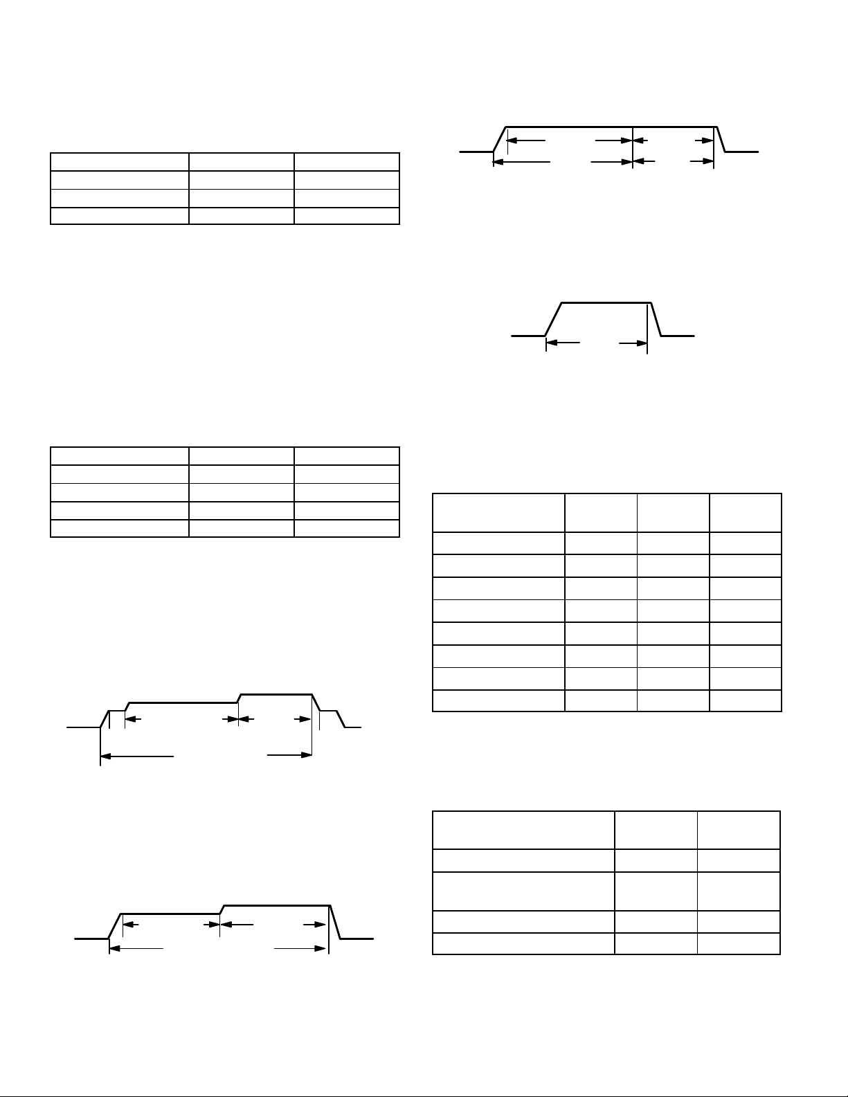
BLOWER DATA
EL296DF045XV36B BLOWER PERFORMANCE (less lter)
BOTTOM RETURN AIR
0 through 0.8 in. w.g. (Heating) and 0 through 1.0 in. w.g. (Cooling) External Static Pressure Range
HEATING
1
Heating Speed
DIP Switch
Settings
+24% 910 1150
+18% 855 1095
+12% 820 1040
+6% 770 990
Factory Default 745 935
–6% 700 880
–12% 665 820
–18% 635 755
1
Cooling Speed
DIP Switch
Settings
Low Medium-Low Medium-High
+ 640 755 850 975 895 1050 1210 1360
Factory Default 580 695 780 880 805 965 1105 1250
– 545 645 720 795 735 865 1000 1130
1
Cooling and heating speeds are based on a combination of DIP switch settings on the furnace control. Refer to Installation Instructions for specic DIP Switch Set-
NOTES - The effect of static pressure is included in air volumes shown.
First stage COOL (two-stage air conditioning units only) is approximately 70% of the same second stage COOL speed position.
Continuous Fan Only speed is selectable at 28%, 38%, 70% and 100% of the selected second stage cooling speed - minimum 250 cfm.
First Stage Heating Speed - cfm Second Stage Heating Speed - cfm
COOLING
First Stage Cooling Speed - cfm Second Stage Cooling Speed - cfm
2
High Low Medium-Low Medium-High
2
First stage HEAT is approximately 91% of the same second stage HEAT.
Lennox Harmony III™ Zone Control Applications - Minimum blower speed is 250 cfm.
tings.
Factory default setting.
2
High
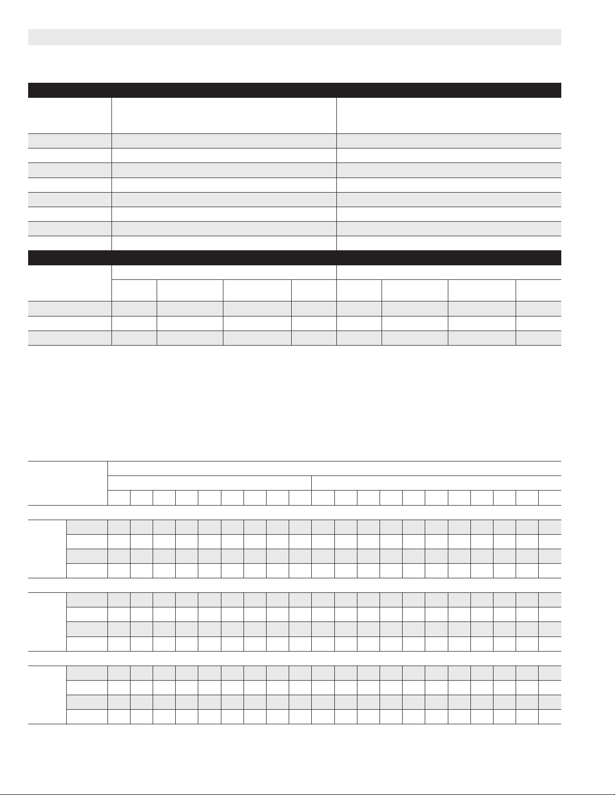
EL296DF045XV36B BLOWER MOTOR WATTS (COOLING)
1
Cooling Speed
DIP Switch
Settings
First Stage Second Stage
0 0.1 0.2 0.3 0.4 0.5 0.6 0.7 0.8 0 0.1 0.2 0.3 0.4 0.5 0.6 0.7 0.8 0.9 1.0
Motor Watts @ Various External Static Pressures - in. wg.
+ Setting
Low 28 44 60 77 93 11 2 128 144 158 59 77 97 121 138 160 182 197 216 241 256
Cooling
Speed
Med-low 47 67 88 105 121 138 161 179 201 131 154 177 202 228 250 277 299 320 344 370
Med-High 69 91 11 3 132 160 183 204 220 246 199 215 248 275 308 340 360 390 407 431 445
High 100 11 7 153 172 192 215 240 260 286 292 313 363 379 419 452 488 5 11 526 523 524
Factory Default
Low 17 34 52 65 82 97 121 132 148 61 79 98 125
Cooling
Speed
Med-low 35 50 70 85 105 125 140 155 175 99 11 5 148 167 188 211 236 256 279 303 317
Med-High 54 72 95 113 131 148 173 189 210 147 170 197 223 252 278 301 330 355 373 398
High 74 96 11 8 141 168 190 212 233 252 216 229 258 303 325 356 390 410 426 448 465
– Setting
Low 17 31 49 61 75 91 107 123 136 46 64 82 101 115 134 155 174 196 205 221
Cooling
Speed
Med-low 28 45 61 77 93 11 2 129 144 159 72 92 114 133 160 184 204 221 247 263 282
Med-High 40 57 77 93 11 2 130 148 165 186 11 2 130 161 183 205 226 252 272
High 57 76 97 119 136 156 179 195 214 155 174 207 235 265 292 3 11 343 370 386 414
141 164 185 201 219 246 259
294 319 341
Page 17
Page 18
BLOWER DATA
EL296DF070XV48B BLOWER PERFORMANCE (less lter)
BOTTOM RETURN AIR
0 through 0.8 in. w.g. (Heating) and 0 through 1.0 in. w.g. (Cooling) External Static Pressure Range
HEATING
1
Heating Speed
DIP Switch
Settings
+24% 1085 1635
+18% 1030 1525
+12% 950 1450
+6% 910 1365
Factory Default 850 1310
–6% 790 1225
–12% 740 1135
–18% 680 1060
1
Cooling Speed
DIP Switch
Settings
Low Medium-Low Medium-High
+ 740 915 1055 1255 1110 1340 1575 1800
Factory Default 660 820 940 1120 995 1230 1420 1650
– 575 735 850 995 880 1085 1290 1460
1
Cooling and heating speeds are based on a combination of DIP switch settings on the furnace control. Refer to Installation Instructions for specic DIP Switch Set-
NOTES - The effect of static pressure is included in air volumes shown.
First stage COOL (two-stage air conditioning units only) is approximately 70% of the same second stage COOL speed position.
Continuous Fan Only speed is selectable at 28%, 38%, 70% and 100% of the selected second stage cooling speed - minimum 380 cfm.
First Stage Heating Speed - cfm Second Stage Heating Speed - cfm
COOLING
First Stage Cooling Speed - cfm Second Stage Cooling Speed - cfm
2
High Low Medium-Low Medium-High
2
First stage HEAT is approximately 91% of the same second stage HEAT.
Lennox Harmony III™ Zone Control Applications - Minimum blower speed is 380 cfm.
tings.
Factory default setting.
2
High
EL296DF070XV48B BLOWER MOTOR WATTS (COOLING)
1
Cooling Speed
DIP Switch
Settings
First Stage Second Stage
0 0.1 0.2 0.3 0.4 0.5 0.6 0.7 0.8 0 0.1 0.2 0.3 0.4 0.5 0.6 0.7 0.8 0.9 1.0
Motor Watts @ Various External Static Pressures - in. wg.
+ Setting
Low 68 88 109 132 154 178 199 213 238 144 169 208 244 270 310 343 378 401 432 457
Cooling
Speed
Med-low 93 120 147 172 198 220 254 274 304 257 276 326 370 398 437 470 492 531 558 598
Med-High 120 152 180 220 254 281 318 344 380 390 428 472 526 574 611 659 706 745 788 820
High 214 237 284 324 352 390 424 456 474 627 604 663 721 775 825 869 908 915 881 864
Factory Default
Low 35 54 74 92 109 129 147 163 191 104 137 162 189
Cooling
Speed
Med-low 75 100 115 140 165 190 210 230 255 188 203 250 297 327 374 399 432 454 486 513
Med-High 99 129 159 179 209 236 270 293 329 304 340 376 418 450 495 533 567 613 637 674
High 157 184 232 264 285 335 365 406 419 454 469 537 589 634 669 724 770 818 833 840
– Setting
Low 27 49 63 73 98 11 6 135 155 168 86 111 135 162 186 206 236 257 283 306 339
Cooling
Speed
Med-low 67 87 109 132 154 177 199 212 238 129 156 187 226 258 288 325 353 385 409 441
Med-High 82 105 127 153 176 196 223 243 269 226 244 290 335 364 402 435 465
High 107 141 164 195 224 263 282 321 347 329 375 403 444 481 526 570 612 656 680 718
219 254 278 312 341 369 400
485 516 556
Page 18
Page 19
BLOWER DATA
EL296DF090XV60C BLOWER PERFORMANCE (less lter)
BOTTOM RETURN AIR
0 through 0.8 in. w.g. (Heating) and 0 through 1.0 in. w.g. (Cooling) External Static Pressure Range
HEATING
1
Heating Speed
DIP Switch
Settings
+24% 1425 1895
+18% 1355 1825
+12% 1280 1740
+6% 1215 1660
Factory Default 1160 1575
–6% 1055 1455
–12% 1010 1365
–18% 950 1265
1
Cooling Speed
DIP Switch
Settings
Low Medium-Low Medium-High
+ 1115 1265 1400 1600 1600 1750 1970 2130
Factory Default 1005 1150 1275 1450 1450 1630 1810 1975
– 890 1065 1150 1270 1270 1450 1645 1810
1
Cooling and heating speeds are based on a combination of DIP switch settings on the furnace control. Refer to Installation Instructions for specic DIP Switch Set-
NOTES - The effect of static pressure is included in air volumes shown.
First stage COOL (two-stage air conditioning units only) is approximately 70% of the same second stage COOL speed position.
Continuous Fan Only speed is selectable at 28%, 38%, 70% and 100% of the selected second stage cooling speed - minimum 450 cfm.
First Stage Heating Speed - cfm Second Stage Heating Speed - cfm
COOLING
First Stage Cooling Speed - cfm Second Stage Cooling Speed - cfm
2
High Low Medium-Low Medium-High
2
First stage HEAT is approximately 91% of the same second stage HEAT.
Lennox Harmony III™ Zone Control Applications - Minimum blower speed is 450 cfm.
tings.
Factory default setting.
2
High
EL296DF090XV60C BLOWER MOTOR WATTS (COOLING)
1
Cooling Speed
DIP Switch
Settings
First Stage Second Stage
0 0.1 0.2 0.3 0.4 0.5 0.6 0.7 0.8 0 0.1 0.2 0.3 0.4 0.5 0.6 0.7 0.8 0.9 1.0
Motor Watts @ Various External Static Pressures - in. wg.
+ Setting
Low 79 108 144 162 207 242 262 293 323 275 299 366 399 449 483 532 584 605 644 680
Cooling
Speed
Med-low 120 156 187 233 261 279 329 368 401 387 409 471 521 562 606 650 688 716 762 800
Med-High 155 202 235 293 317 369 407 453 502 547 577 622 667 744 795 835 872 910 950 963
High 268 299 366 399 449 483 532 584 605 780 775 8 11 898 942 994 1048 1071 1082 1080 1073
Factory Default
Low 56 86 111 140 170 200 232 259 282 186 219 270 308
Cooling
Speed
Med-low 93 11 8 152 195 223 254 283 306 344 278 304 365 420 450 510 544 592 640 665 698
Med-High 123 161 201 228 260 310 341 381 416 446 475 528 582 616 662 686 747 780 823 855
High 182 219 270 308 361 390 431 489 517 576 603 654 704 756 809 871 902 939 972 975
– Setting
Low 48 69 101 120 152 175 201 218 249 11 8 155 181 232 259 299 340 376 402 438 476
Cooling
Speed
Med-low 65 94 123 150 185 220 250 278 296 177 205 267 304 353 390 430 486 515 563 587
Med-High 93 118 152 195 223 254 283 306 344 301 322 392 439 468 531 568 599
High 116 155 181 232 259 299 340 376 402 446 475 528 582 616 662 686 747 780 823 855
361 390 431 489 517 555 590
647 678 721
Page 19
Page 20

BLOWER DATA
EL296DF110XV60C BLOWER PERFORMANCE (less lter)
BOTTOM RETURN AIR
0 through 0.8 in. w.g. (Heating) and 0 through 1.0 in. w.g. (Cooling) External Static Pressure Range
HEATING
1
Heating Speed
DIP Switch
Settings
+24% 1535 2015
+18% 1445 1935
+12% 1370 1855
+6% 1300 1760
Factory Default 1220 1645
–6% 1135 1545
–12% 1070 1420
–18% 1000 1335
1
Cooling Speed
DIP Switch
Settings
Low Medium-Low Medium-High
+ 1095 1265 1395 1585 1585 1790 1990 2180
Factory Default 965 1130 1285 1440 1440 1630 1845 2005
– 860 1035 1130 1275 1275 1475 1655 1845
1
Cooling and heating speeds are based on a combination of DIP switch settings on the furnace control. Refer to Installation Instructions for specic DIP Switch Set-
NOTES - The effect of static pressure is included in air volumes shown.
First stage COOL (two-stage air conditioning units only) is approximately 70% of the same second stage COOL speed position.
Continuous Fan Only speed is selectable at 28%, 38%, 70% and 100% of the selected second stage cooling speed - minimum 450 cfm.
First Stage Heating Speed - cfm Second Stage Heating Speed - cfm
COOLING
First Stage Cooling Speed - cfm Second Stage Cooling Speed - cfm
2
High Low Medium-Low Medium-High
2
First stage HEAT is approximately 91% of the same second stage HEAT.
Lennox Harmony III™ Zone Control Applications - Minimum blower speed is 450 cfm.
tings.
Factory default setting.
2
High
EL296DF110XV60C BLOWER MOTOR WATTS (COOLING)
1
Cooling Speed
DIP Switch
Settings
First Stage Second Stage
0 0.1 0.2 0.3 0.4 0.5 0.6 0.7 0.8 0 0.1 0.2 0.3 0.4 0.5 0.6 0.7 0.8 0.9 1.0
Motor Watts @ Various External Static Pressures - in. wg.
+ Setting
Low 71 99 147 166 202 240 271 302 337 248 280 333 374 429 469 511 548 594 619 677
Cooling
Speed
Med-low 127 159 198 225 256 301 325 365 390 409 427 496 531 587 632 665 721 742 781 805
Med-High 162 204 242 287 316 371 408 446 487 563 589 651 703 755 808 860 888 932 970 1007
High 243 280 333 374 429 469 511 548 594 866 850 915 963 1020 1056 1091 1127 1141 1136 1131
Factory Default
Low 57 88 117 140 165 196 232 259 283 167 214 244 291
Cooling
Speed
Med-low 77 11 2 147 172 209 250 283 317 345 275 321 348 418 447 505 546 597 632 668 716
Med-High 122 154 199 230 268 300 331 373 411 461 493 547 572 628 666 703 745 777 819 860
High 167 214 244 291 331 380 405 467 497 601 626 688 730 787 823 880 924 963 994 1011
– Setting
Low 44 67 99 11 5 144 167 197 215 245 126 165 201 232 262 305 334 373 417 451 479
Cooling
Speed
Med-low 66 97 123 153 186 216 247 275 303 187 219 272 308 360 391 432 479 514 559 588
Med-High 77 112 147 172 209 250 283 317 345 308 341 390 430 490 528 569 617
High 127 165 201 232 262 305 334 373 417 461 493 547 572 628 666 703 745 777 819 860
331 380 405 467 497 539 583
640 691 724
Page 20
Page 21
On-Board Links
Note: In icomfortt systems with a conventional outdoor
unit (non-communicating), the on-board clippable links
must be set to properly configure the system.
damage. Refer to table 12 for operation sequence in ap
plications including EL296DFV, a thermostat which fea
tures humidity control and a single-speed outdoor unit.
Table 13 gives the operation sequence in applications with
a two-speed outdoor unit.
On-Board Link W951 Heat Pump (R to O)
WARNING
Carefully review all configuration information pro
vided. Failure to properly set DIP switches, jumpers
and on-board links can result in improper operation!
On-board link W951 is a clippable connection between ter
minals R and O on the integrated control. W951 must be cut
when the furnace is installed in applications which include a
heat pump unit and a thermostat which features dual fuel
use. If the link is left intact, terminal “O” will remain ener
On-Board Link W914 Dehum or Harmony (R to DS)
On-board link W914, is a clippable connection between ter
minals R and DS on the integrated control. W914 must be
cut when the furnace is installed with either the Harmony
III zone control or a thermostat which features humidity
control. If the link is left intact the PMW signal from the Har
mony III control will be blocked and also lead to control
gized eliminating the HEAT MODE in the heat pump.
On-Board Link W915 2 Stage Compr (Y1 to Y2)
On-board link W915 is a clippable connection between ter
minals Y1 and Y2 on the integrated control. W915 must be
cut if two-stage cooling will be used. If the Y1 to Y2 link is
not cut the outdoor unit will operate in second-stage cool
ing only.
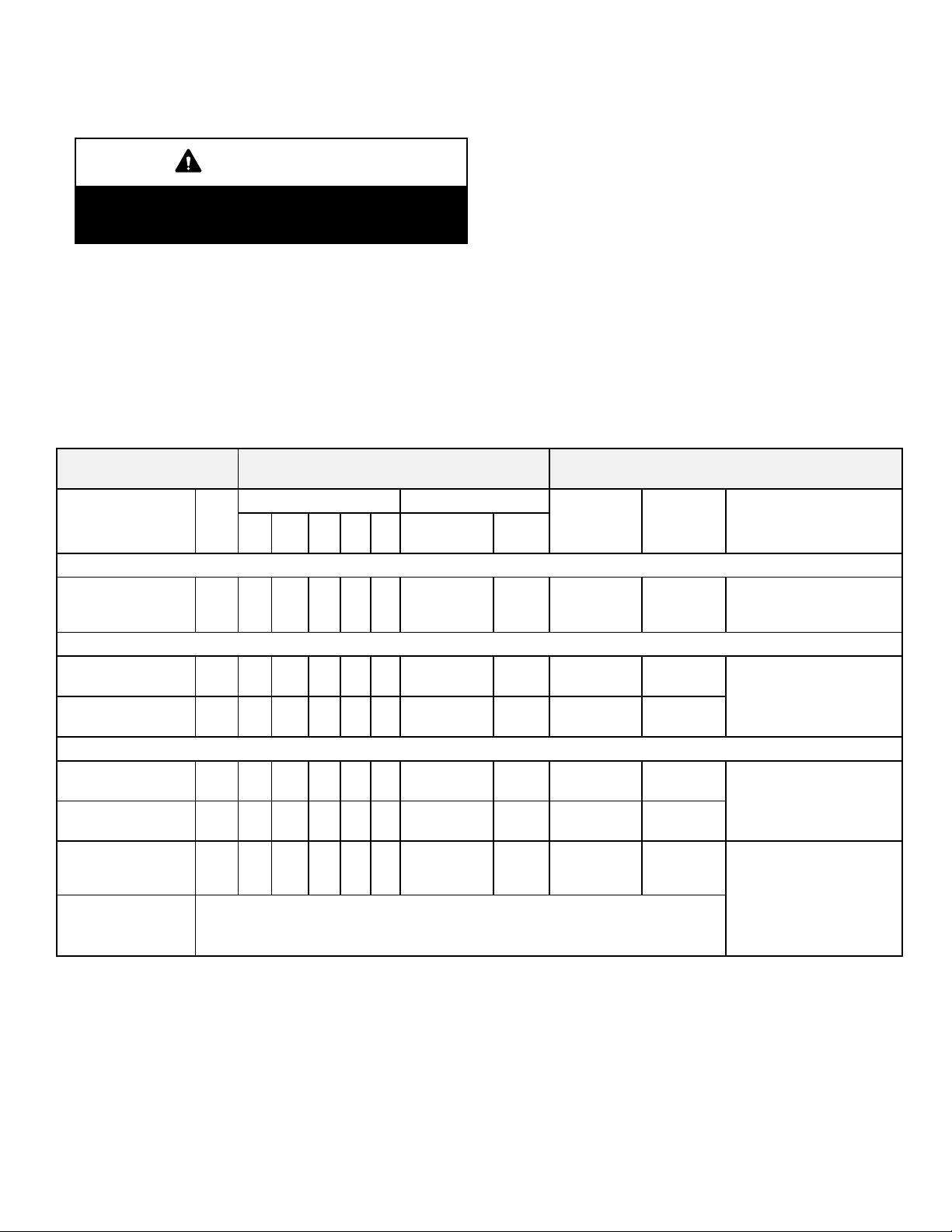
TABLE 12
OPERATING SEQUENCE
EL296DFV, Non-Communicating Thermostat with Humidity Control Feature and Single-Speed Outdoor Unit
OPERATING
SEQUENCE
System
Condition
NO CALL FOR DEHUMIDIFICATION
Normal Operation 1 On On On Acceptable
BASIC MODE (only active on a Y1 thermostat demand)
Normal Operation 1 On On On Acceptable
Dehumidification
Call
PRECISION MODE (operates independent of a Y1 thermostat demand)
Normal Operation 1 On On On Acceptable
Dehumidification
call
Dehumidification
call ONLY
Step
Jumpers at indoor unit with a single stage outdoor unit
With Condensing unit - Cut W914 (R to DS) on SureLight
With Heat Pump - Cut W914 (R to DS) & W951 (R to O) on SureLight
Thermostat Demand Relative Humidity
Y1 O G
2 On On On Demand 0 VAC High 70%*
2 On On On Demand
1 On On On Demand
SYSTEM DEMAND SYSTEM RESPONSE
W
1
Status D
24
VAC
24
VAC
24
VAC
0
VAC
0
VAC
Compressor
High 100%
High 100%
High 100%
High 70%*
High 70%*
®
control
®
Blower
(COOL)
control
CFM
Comments
Compressor and indoor
blower follow thermostat
demand
ComfortSense® 7000
thermostat energizes Y1
and de-energizes D on a
call for de-humidification
Dehumidification mode
begins when humidity is
greater than set point
®
ComfortSense
thermostat
maintain room humidity
setpoint by allowing the
room space to maintain a
cooler room thermostat
setpoint**
7000
will try to
Use Dave Lennox ComfortSense® 7000 thermostat Y2081 4 heat / 2 cool for this application
*Dehumidification blower speed is 70% of COOL speed for all units .
**In Precision mode, ComfortSense
®
7000 thermostat will maintain room temperature up to 2 °F (1.2°C) cooler than room setting.
Page 21
Page 22
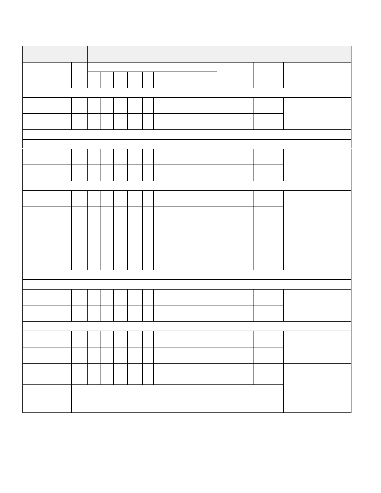
TABLE 13
OPERATING SEQUENCE
EL296DFV, Non-Communicating Thermostat with Humidity Control Feature and Two-Speed Outdoor Unit
OPERATING
SEQUENCE
SYSTEM DEMAND SYSTEM RESPONSE
Thermostat Demand Relative Humidity
System
Condition
Ste
p
Y1 Y2 O G
W1W
2
Status D
NO CALL FOR DEHUMIDIFICATION
Normal Opera
tion - Y1
Normal Opera
tion - Y2
1 On On On Acceptable
2 On On On On Acceptable
24
VAC
24
VAC
ROOM THERMOSTAT CALLS FOR FIRST STAGE COOLING
BASIC MODE (only active on a Y1 thermostat demand)
Normal Opera
tion
Dehumidification
Call
1 On On On Acceptable
2 On On On On Demand
24
VAC
0
VAC
PRECISION MODE (operates independent of a Y1 thermostat demand)
Normal Opera
tion
Dehumidification
call
Dehumidification
call ONLY
1 On On On Acceptable
2 On On On On Demand
1 On On On On Demand
24
VAC
0
VAC
0
VAC
ROOM THERMOSTAT CALLS FOR FIRST AND SECOND STAGE COOLING
BASIC MODE (only active on a Y1 thermostat demand)
Normal Opera
tion
Dehumidification
Call
1 On On On On Acceptable
2 On On On On Demand
24
VAC
0
VAC
PRECISION MODE (operates independent of a Y1 thermostat demand)
Normal Opera
tion
Dehumidification
call
1 On On On Acceptable
2 On On On On Demand
24
VAC
0
VAC
Compressor
Low 70%*
High 100%
Low 70%*
High 70%**
Low 70%*
High 70%**
High 70%**
High 100%
High 70%**
Low 70%*
High 70%**
Blower
CFM
(COOL)
Comments
Compressor and indoor
blower follow thermostat
demand
ComfortSense
®
7000
thermostat energizes Y2
and de-energizes D on a
call for de-humidification
Dehumidification mode
begins when humidity is
greater than set point
ComfortSense® 7000
thermostat will try to
maintain room humidity
setpoint by allowing the
room space to maintain
a cooler room thermostat
setpoint***
ComfortSense® 7000
thermostat energizes Y2
and de-energizes D on a
call for de-humidification
Dehumidification mode
begins when humidity is
greater than set point
Dehumidification
call ONLY
1 On On On On Demand
0
VAC
Jumpers at indoor unit with a two stage outdoor unit
Cut factory jumper from Y1 to Y2 or cut W915 (Y1 to Y2)
With Condensing unit - Cut W914 (R to DS) on SureLight
®
control
With Heat Pump - Cut W914 (R to DS) & W951 (R to O) on SureLight
Use Dave Lennox ComfortSense® 7000 thermostat Y2081 4 heat / 2 cool for this application.
*Normal operation first stage cooling blower speed is 70% COOL speed.
**Dehumidification blower speed is, reduced to 70% of COOL.
***In Precision mode, ComfortSense
®
7000 thermostat will maintain room temperature up to 2 °F (1.2°C) cooler than room setting.
Page 22
High 70%**
®
control
ComfortSense® 7000
thermostat will try to
maintain room humidity
setpoint by allowing the
room space to maintain
a cooler room thermostat
setpoint***
Page 23

B- Indoor Blower Motor
Power Choke
(4 and 5 Ton Only)
To Remove Blower From Unit: Remove access panels,
Control box, Bolts and Wiring Jackplugs.
Blower Motor
(B3)
Then Slide Out Front of Unit.
FIGURE 6
WARNING
During blower operation, the ECM motor emits ener
gy that may interfere with pacemaker operation. In
terference is reduced by both the sheet metal cabinet
and distance.
The motor communicates with the integrated control via a
2-way serial connection. The motor receives all necessary
functional parameters from the integrated control and does
not rely on a factory program like traditional variable speed
motors. EL296DFV units use a three‐phase, electronically
controlled D.C. brushless motor (controller converts single
phase a.c. to three phase D.C.), with a permanent‐magnet‐
type rotor (figure 7). Because this motor has a permanent
magnet rotor it does not need brushes like conventional D.C.
motors.
The stator windings are split into three poles which are electri
cally connected to the controller. This arrangement allows
motor windings to turn on and off in sequence by the con
troller.
IMPORTANT
Earlier ECM motors used on other Lennox furnace
models are not interchangeable with motors used on
the EL296 furnace line.
A solid‐state controller is permanently attached to the
motor. The controller is primarily an A.C. to D.C. con
verter. Converted D.C. power is used to drive the motor.
The controller contains a microprocessor which moni
tors varying conditions inside the motor (such as motor
workload).
BLOWER MOTOR COMPONENTS
STATOR
(WINDINGS)
BEARING
ROTOR
FIGURE 7
The controller uses sensing devices to sense what position
the rotor is in at any given time. By sensing the position of the
rotor and then switching the motor windings on and off in se
quence, the rotor shaft turns the blower.
All EL296DFV blower motors use single phase power.
An external run capacitor is not used. The motor uses
permanently lubricated ball‐type bearings.
Internal Operation
The motor is controlled via serial communication between
the integrated control on the furnace and the controller at
tached to the motor shell. The messages sent back and
forth between the two controls serve to communicate rota
tional direction, demand, motor size, current draw, torque,
and rpm, among other variables.
Motor rpm is continually adjusted internally to maintain
constant static pressure against the blower wheel. The control
ler monitors the static work load on the motor and motor amp‐
draw to determine the amount of rpm adjustment. Blower rpm
may be adjusted any amount in order to maintain a constant
cfm as shown in Blower Ratings Tables. The cfm remains rel
atively stable over a broad range of static pressure. Since the
blower constantly adjusts rpm to maintain a specified cfm, mo
tor rpm is not rated. Hence, the terms “cool speed”, “heat
speed ” or “speed tap” in this manual, on the unit wiring dia
gram and on blower B3, refer to blower cfm regardless of mo
tor rpm.
Initial Power Up
When line voltage is applied to B3, there will be a large inrush
of power lasting less than 1/4 second. This inrush charges a
bank of DC filter capacitors inside the controller. If the discon
nect switch is bounced when the disconnect is closed, the dis
connect contacts may become welded. Try not to bounce the
disconnect switch when applying power to the unit.
Page 23
Page 24

Motor Start‐Up
When B3 begins start‐up, the motor gently vibrates back and
forth for a moment. This is normal. During this time the elec
tronic controller is determining the exact position of the rotor.
Once the motor begins turning, the controller slowly eases
the motor up to speed (this is called “soft‐start”). The motor
may take as long as 10‐15 seconds to reach full speed. If the
motor does not reach 200 rpm within 13 seconds, the motor
shuts down. Then the motor will immediately attempt a re
start. The shutdown feature provides protection in case of a
frozen bearing or blocked blower wheel. The motor may at
tempt to start eight times. If the motor does not start after the
eighth try, the controller locks out. Reset controller by momen
tarily turning off power to unit.
The DC filter capacitors inside the controller are connected
electrically to the motor supply wires. The capacitors take
approximately 5 minutes to discharge when the disconnect
is opened. For this reason it is necessary to wait at least 5
minutes after turning off power to the unit before attempt
ing to service motor.
DANGER
Disconnect power from unit and
wait at least five minutes to allow
capacitors to discharge before at
tempting to service motor. Failure
to wait may cause personal injury
or death.
Power Choke (L13)
A choke coil is used on EL296DFV 4 and 5 ton units
equipped with 1 hp motors. The choke is located on the
blower housing and is used to suppress transient current
spikes.
Troubleshooting Motor Operation
To verify motor operation see steps below and figures 8
and 9.
1- Remove J48 (5 pin power plug) from P48 on the mo
tor.
2- With the power on at the furnace and door switch de
pressed, use a test meter to verify 120V between pins
4 and 5 on J48.
3- Reconnect J48 to P48 on the motor.
4- Remove J49 (4 pin low voltage connector) from P49
on the motor.
5- Using test jumpers, apply 24V to pins 3 and 4 on P49
on the motor.
Note: Do not apply 24V to pins 2 and 4 on P49. Doing so
will cause permanent damage to the motor.
6- Motor should run at 75%.
7- Test is complete. Remove jumpers and reconnect
plugs.
Another option is to use the TECMate PRO motor tester
with the 16 to 4 pin adaptor. The use of the TECMate PRO
isolates the motor from the integrated control. Follow the
instructions provided with the kit. If the motor runs do not
replace.
Page 24
Page 25

BLOWER B3 HARNESS CONNECTORS
P48 5 Pin
SHAFT
BLOWER B3 HARNESS CONNECTORS
P48 5 Pin
P49 4 Pin
SHAFT
MOTOR with INTEGRATED
CONTROLLER
J48 5 Pin
J49 4 Pin
J49 4 Pin Control Connector
J48 5 Pin Line Voltage Connector
FIGURE 8
P49 4 Pin
MOTOR with INTEGRATED
CONTROLLER
P48 5 Pin
P49 4 Pin
1
2
3
4
5
120v
0
J48 Connector
240v
Page 25
J48 Connector
installed on motor
P49 4 Pin
24v Transformer
J49 Connector
FIGURE 9
Page 26

Troubleshooting Motor Windings
Ensure that motor windings are not damaged by perform
ing the following tests:
NOTE - If your ohm meter is not an auto-ranging type, set it
to the highest ohm scale (100k ohms or greater) before
performing tests.
TABLE 14
Flame Signal in Microamps
Scale
2M
200k
20k
2k
200 two hundred ohm 0-200
Measurement Range
in words ohms
two megohm -- two
million ohms
two hundred kilohm
-- two hundred thou
sand ohms
twenty kilohm -twenty thousand
ohms
two kilohm -- two
thousand ohms
0-2,000,000
0-200,000
0-20,000
0-2,000
1 - The lead-to-lead resistance across any two leads
should be less than 20 ohms.
2 - Each lead-to-lead resistance should be the same.
If the measured resistance is greater than 20 ohms, re
place the motor and control module.
Test B
FIGURE 12
C- Heating Components
1. Ignitor
®
The SureLight
ignitor is made of durable silicon nitride. Ig
nitor longevity is enhanced by controlling voltage to the ig
nitor. The integrated control provides a regulated 120 volts
to the ignitor for a consistent ignition and long ignitor life.
Ohm value should be 39 to 70. See figure 13 for ignitor
location and figure 14 for ignitor check out.
FIGURE 10
TEST A
Measure the resistance between each of the three motor
leads (3-pin plug) and the unpainted part of the end shield.
If the winding resistance to ground is <100k
ohms, replace the motor and control module. If
the resistance to ground is >100k, the motor
windings are fine. Proceed to Test B.
Test A
FIGURE 11
TEST B
Use an ohmmeter to measure the motor phase-to-phase
resistance by checking these combinations of the the 3-pin
motor plug. For the purpose of this test, start at either end of
the connector as lead 1.
NOTE - The EL296DFV(X) furnace contains electronic
components that are polarity sensitive. Make sure that the
furnace is wired correctly and is properly grounded.
2. Flame Sensor
A flame sensor is located on the left side of the burner sup
port. See figure 13. The sensor tip protrudes into the flame
envelope of the left-most burner. The sensor can be re
moved for service without removing any part of the burn
ers. During operation, flame is sensed by current passed
through the flame and sensing electrode. The SureLight
control allows the gas valve to remain open as long as
flame signal is sensed. To check flame sense signal use the
push-button found on the integrated control and go to Field
Test Mode. The menu will display the flame signal. See
table 15 for flame signal.
TABLE 15
Flame Signal in Microamps
Normal
Low Drop Out
2.6 or greater 2.5 or less 1.1
3. Gas Valve
The valve (figure 51) is internally redundant to assure safe
ty shut-off. If the gas valve must be replaced, the same type
valve must be used.
24VAC terminals and gas control knob are located on the
valve. A wire harness connects the terminals from the gas
valve to the electronic ignition control. 24V applied to the termi
nals energizes the valve.
Inlet and outlet pressure taps are located on the valve. A regu
lator adjustment screw is located on the valve.
LPG change over kits are available from Lennox. Kits include
burner orifices and a gas valve.
Page 26
Page 27

4. Flame Rollout Switches (S47)
Flame rollout switch is a high temperature limit located on
top of the burner box, one on each side.- See figure 13. The
limit is a N.C. SPST manual‐reset limit. When S47 senses
rollout, the circuit breaks and the ignition control immedi
ately stops ignition and closes the gas valve. Rollout can be
caused by a blocked heat exchanger, flue or lack of com
bustion air. The switch is factory set to trip (open) at 210°F
and cannot be adjusted. The switch can be manually reset.
To manually reset a tripped switch, push the reset button lo
cated on the control.
5. Burners
All units use inshot burners. Burners are factory set and re
quire no adjustment. Always operate the unit with the burner
box front panel in place. Each burner uses an orifice (see
table 28 for orifice size) that is precisely matched to the burn
EL296DFV HEATING COMPONENTS
er input. Burners can be removed as a one piece assembly
for service. If burner assembly has been removed, it is critical
to align center of each burner to the center of the clamshell
when re-installing. See more detail in Section VI- MAINTE
NANCE.
6. Primary Limit Control (S10)
The primary limit (S10) is located in the heating vestibule pan
el. When excess heat is sensed in the heat exchanger, the
limit will open. If the limit is open, the furnace control energizes
the supply air blower and closes the gas valve. The limit auto
matically resets when unit temperature returns to normal. The
switch must reset within three minutes or the SureLight control
will go into Watch guard for one hour. The switch is factory
set and cannot be adjusted. The switch may have a different
set point for each unit model number. See Lennox Repair
Parts Handbook if limit switch must be replaced,
Burner Assembly
Intake Air Top Cap
Rollout Switch
Sensor
Rollout Switch
Ignitor
Burner Box Cover
Manifold And Gas Orifices
Two-Stage Gas Valve
FIGURE 13
Page 27
Page 28

Check ignitor circuit for correct resistance.
Test 1
Remove 4-pin plug from control.
Check ohms reading across terminals 1 and 5.
If value is correct, this is the only test needed.
If the reading on the meter is not correct, (0 or infinity)
then a second test is needed.
Meter
(set to ohms)
EL296DFV Ignitor Check
Integrated Control Detail
Seperate the 2-pin jack-plug near the manifold and check
Check ignitor for correct resistance.
resistance of ignitor at the plug. Reading should be
between 39 and 70 ohms. If the reading is correct, then
the problem is with the wiring between the jack-plug and
the control. If reading is not correct, the issue is the ignitor.
Test 2
Meter
(set to ohms)
Insert meter probes into terminals 1 and 5 (use small
Check ignitor for correct voltage
diameter probes in order not to damage plug).
Check voltage during 20 second ignitor warm up period.
Voltage should read 120 volts +
these values, check for correct supply voltage to furnace.
Test 3
10%. If voltage reads below
Integrated Control Detail
Meter
(set to AC volts)
Integrated Control Detail
FIGURE 14
Page 28
Page 29

7. Combustion Air Inducer (B6) and
Cold End Header Box
All EL296DFV(X) units use a two-stage combustion air in
ducer to move air through the burners and heat exchanger
during heating operation. The blower uses a 120VAC mo
tor. The motor operates during all heating operation and is
controlled by integrated control control A92. The inducer
also operates for 15 seconds before burner ignition (pre‐
purge) and for 5 seconds after the gas valve closes (post‐
purge). The inducer operates on low speed during firststage heat, then switches to high speed for second stage
heat.
NOTE - Each furnace model uses a unique CAI. Refer to
Lennox Repair Parts listing for correct inducer for replace
ment.
The combustion air inducer is installed on the cold end
header box. The cold end header box is a single piece
made of hard plastic. The box has an internal channel
where the combustion air inducer creates negative pres
sure at unit start up. The channel contains an orifice used
to regulate flow created by the combustion air inducer.
The box has pressure taps for the combustion air inducer
pressure switch hoses. The pressure switch measures
the pressure differential across the combustion air induc
er orifice or difference in the channel and the box. If re
placement is necessary the gaskets used to seal the
box to the vestibule panel and the combustion air in
ducer to the box, must also be replaced.
A proving switch connected to the combustion air inducer ori
fice plate is used to prove inducer operation. The combustion
air inducer orifice will be different for each model. See table
16 for orifice sizes. The pressure switch measures the pres
sure differential across the combustion air inducer orifice.
When the proving switch opens, the furnace control (A92) im
mediately closes the gas valve to prevent burner operation.
TABLE 16
EL296DFV(X) Unit
C.A.I. Orifice Size
The switches are a single‐pole single‐throw proving switch
electrically connected to the integrated control. The purpose
of the switch is to prevent burner operation if the combustion
air inducer is not operating or if the flue becomes obstructed.
On heat demand (first or second stage) the switch senses
that the combustion air inducer is operating. It closes a cir
cuit to the integrated control when pressure inside the com
bustion air inducer decreases to a certain set point.
Set points vary depending on unit size. See table 17. The
pressure sensed by the switch is negative relative to atmo
spheric pressure. If the flue becomes obstructed during op
eration, the switch senses a loss of negative pressure
(pressure becomes more equal with atmospheric pres
sure) and opens the circuit to the furnace control and gas
valve. A bleed port on the switch allows relatively dry air in
the vestibule to purge switch tubing, to prevent condensate
build up.
COMBUSTION AIR PRESSURE SWITCH
Tap (negative - )
Tap (positive +)
Low Fire Switch
3/16 Terminals
" Terminals
1/4
High Fire Switch
FIGURE 15
-045 0.618
-070 0.810
-090 0.920
-110 1.040
8. Combustion Air Inducer
Pressure Switch (S18)
EL296DFV(X) series units are equipped with a dual com
bustion air pressure switch (first and second stage) located
on the combustion air inducer orifice bracket. See figure 15.
The switch is connected to the combustion air inducer hous
ing by means of a flexible silicone hose. It monitors negative
air pressure in the combustion air inducer housing.
Page 29
NOTE - The switch is factory set and is not field adjustable.
It is a safety shut‐down control in the furnace and must not
be by-passed for any reason. If switch is closed or bypassed, the control will not initiate ignition at start up.
TABLE 17
EL296DFV(X)
Unit
-045 0.35 0.60
-070 0.45 0.90
-090 0.50 0.90
-110 0.45 0.90
Set Point Low
Heat
Set Point High Heat
Page 30

Pressure Switch Check
To check pressure switch differential, refer to figure 16 and
use the provided fittings and tubing to follow the steps be
low.
1 - Remove thermostat demand and allow unit to cycle
off.
2 - Remove the tubing from the negative side (red and black
or red) and positive side (black) of the pressure switch
(leave both connected to cold end header box).
3 - Take the 2” length square tubing and connect to the
positive (+) side of the pressure switch. Take the 10”
length square tubing and tee into the tubing from the
positive side of the cold end header box and the other
side of the 2” square tubing. Connect the other end of
the 10” square tubing the the positive (+) side of the
measuring device.
4 - Take a second piece the 2” length square tubing and
connect to the negative (-) side of the pressure switch.
Take a second piece of 10” length square tubing and
tee into the tubing from the negative (-) side of the cold
end header box and the other side of the 2” square tub
ing. Connect the other end of the 10” square tubing the
the negative (-) side of the measuring device.
PRESSURE SWITCH CHECK
Black Tubing
(positive +)
Te e
5 - Operate unit and observe manometer reading.
Readings will change as heat exchanger warms.
a. Take one reading immediately after start‐up.
b. Take a second reading after unit has reached steady
state (approximately 5 minutes). This will be the pres
sure differential.
The pressure differential should be at least
0.15” greater than those listed in the table 17. Read
ings in table are the set points or “break points”.
6 - Remove thermostat demand and allow to cycle off.
7 - Replace original pressure switch tubing.
NOTE - Pressure differential values (set point) in table are
the ”break”, or ”open” specifications. ”Make”, or ”close”
pressure differentials are 0.15” greater than the set points
listed in table.
2” long Square
Tubing
Red and Black
or Red Tubing
(negative -)
10” Long Square Tubing
Measuring Device
FIGURE 16
Page 30
Page 31

II-PLACEMENT AND INSTALLATION
Pipe & Fittings Specifications
All pipe, fittings, primer and solvent cement must conform
with American National Standard Institute and the Ameri
can Society for Testing and Materials (ANSI/ASTM) stan
dards. The solvent shall be free flowing and contain no
lumps, undissolved particles or any foreign matter that ad
versely affects the joint strength or chemical resistance of
the cement. The cement shall show no gelation, stratifica
tion, or separation that cannot be removed by stirring. Re
fer to the table 18 below for approved piping and fitting ma
terials.
CAUTION
Solvent cements for plastic pipe are flammable liq
uids and should be kept away from all sources of
ignition. Do not use excessive amounts of solvent
cement when making joints. Good ventilation should
be maintained to reduce fire hazard and to minimize
breathing of solvent vapors. Avoid contact of ce
ment with skin and eyes.
PIPING AND FITTINGS SPECIFICATIONS
Schedule 40 PVC (Pipe) D1785
Schedule 40 PVC (Cellular Core Pipe) F891
Schedule 40 PVC (Fittings) D2466
Schedule 40 CPVC (Pipe) F441
Schedule 40 CPVC (Fittings) F438
SDR-21 PVC or SDR-26 PVC (Pipe) D2241
SDR-21 CPVC or SDR-26 CPVC (Pipe) F442
Schedule 40 ABS Cellular Core DWV (Pipe) F628
Schedule 40 ABS (Pipe) D1527
Schedule 40 ABS (Fittings) D2468
ABS-DWV (Drain Waste & Vent)
(Pipe & Fittings)
PVC-DWV (Drain Waste & Vent)
Pipe & Fittings)
PRIMER & SOLVENT CEMENT
PVC & CPVC Primer F656
PVC Solvent Cement D2564
CPVC Solvent Cement F493
ABS Solvent Cement D2235
PVC/CPVC/ABS All Purpose Cement For
Fittings & Pipe of the same material
ABS to PVC or CPVC Transition Solvent
Cement
CANADA PIPE & FITTING & SOLVENT
CEMENT
PVC & CPVC Pipe and Fittings
PVC & CPVC Solvent Cement
ABS to PVC or CPVC Transition Cement
POLYPROPYLENE VENTING SYSTEM ULC-S636
PolyPro® by Duravent ULC-S636
InnoFlue® by Centrotherm ULC-S636
TABLE 18
D2661
D2665
ASTM
SPECIFICATION
D2564, D2235, F493
D3138
MARKING
ULCS636
IMPORTANT
EL296DFV exhaust and intake connections are made
of PVC. Use PVC primer and solvent cement when
using PVC vent pipe. When using ABS vent pipe, use
transitional solvent cement to make connections to
the PVC fittings in the unit.
Use PVC primer and solvent cement or ABS solvent cement
meeting ASTM specifications, refer to Table 18. As an alter
nate, use all purpose cement, to bond ABS, PVC, or CPVC
pipe when using fittings and pipe made of the same materi
als. Use transition solvent cement when bonding ABS to ei
ther PVC or CPVC.
Low temperature solvent cement is recommended during
cooler weather. Metal or plastic strapping may be used for
vent pipe hangers. Uniformly apply a liberal coat of PVC
primer for PVC or use a clean dry cloth for ABS to clean in
side socket surface of fitting and male end of pipe to depth
of fitting socket.
Canadian Applications Only - Pipe, fittings, primer
and solvent cement used to vent (exhaust) this ap
pliance must be certified to ULC S636 and supplied by a
single manufacturer as part of an approved vent (ex
haust) system. In addition, the first three feet of vent
pipe from the furnace flue collar must be accessible for
inspection.
Venting Options
The EL296DFV is shipped with vent exhaust / air intake
connection at the top cap. See figure 17. Using parts pro
vided, the furnace may be field modified to have these
connections on the right side of the furnace cabinet. See
figure 19 and follow the steps below. For left side venting
order kit 87W73.
1 - Remove inner blower door.
2 - Loosen hose clamps which attach rubber fittings to the
white PVC pipes inside the vestibule area. See figure
17.
3 - Loosen the clamp which secures the pipes at the blow
er deck. See figure 17.
4 - Remove white PVC pipes, slide up and out thru the top
cap.
5 - Remove the black plastic fitting in top cap which pre
viously aligned the PVC pipes.
6 - Remove the remaining parts of the pipe clamp at the
blower deck.
7 - Remove the sheet metal patch plate on the side of the
cabinet which covers the openings for side venting op
tion. Save screws for reuse.
8 - Re-use the patch plate to cover the hole in the top cap.
See figure 18. Remove the 2 screws which secure the
top cap to the furnace on the right side and re-install
securing the right edge of the patch plate and the right
side of the top cap to the furnace. Use 2 self-drilling
sheet metal screws (provided) to finish securing the
left edge of the patch plate on the left side.
Page 31
Page 32

9 - Use a utility knife to cut out the cabinet insulation for
the right side vent / air intake.
10 -Install the two 90° street elbows (provided) through the
side of the cabinet. The male side of each elbow
should extend down through the blower deck and con
nect to the rubber fittings below. Once the elbows are
properly positioned, tighten each clamp.
11 - Peel protective backing from side vent sealing gaskets
(2) and apply to side vent sealing plates (2) as shown
in figure 19.
12 -Install the side vent sealing plates and gaskets on the
exterior of the cabinet as shown in figure 19. Secure
with six mounting screws (four reused and two pro
vided from bag assembly). Holes are pre-punched in
the parts and cabinet, no drilling is required.
13 -Install sheet metal screws (provided) to seal extra two
holes in cabinet not used with side vent clamps.
Patch Plate Top Cap
Sheet Metal
Patch Plate
IMPORTANT
Side vent sealing plates and side vent sealing gas
kets must be used when converting to right side
venting. Failure to use gaskets and plates may lead
to improper operation of unit.
Top Vent Configuration
Exhaust/Air
Intake Connections
Pipe Clamp
FIGURE 18
FIGURE 17
Hose Clamp
Page 32
Page 33

Right Side Vent Configuration
Sealing Plate
Side Vent
Sealing Gaskets
Side Vent
Exhaust
Street Elbows (2)
FIGURE 19
Intake
Page 33
Page 34

Input Size
045
070
090
110
OUTDOOR TERMINATION USAGE*
TABLE 19
STANDARD CONCENTRIC
Flush
Vent
Pipe
Dia. in.
Mount
Kit
51W11
(US)
51W12
2 inch 3 inch 2 inch
22G44 (US)
4
30G28 (CA)
(CA)
2
2-1/2
3
2
2-1/2
3
2
2-1/2
3
3
YES YES
3
YES YES
3
YES YES
3
YES YES
3
YES YES
3
YES YES
3
YES YES YES
3
YES YES YES
3
YES YES YES
2 YES YES YES
2-1/2 YES YES
3 YES YES
Wall Kit Wall Ring Kit
44J40
(US)
4
81J20 (CA)
1
YES
1
YES
1
YES
1
YES
1
YES
1
YES
15F74
1
YES
1
YES
1
YES
1
YES
1
YES
1
YES
1-1/2 inch 2 inch 3 inch
Field
Fabricated
5
YES
5
YES
5
YES
5
YES
5
YES
5
YES
5
YES YES YES
5
YES YES YES
5
YES YES YES
5
YES YES YES
5
YES YES YES
5
YES YES YES
71M80
(US)
4
44W92
(CA)
2
YES
2
YES
2
YES
2
YES
2
YES
2
YES
69M29
(US)
4
44W92
(CA)
60L46 (US)
4
44W93 (CA)
NOTE - Standard Terminations do not include any vent pipe or elbows external to the structure. Any vent pipe or elbows external to the structure must be included in total vent length
calculations. See vent length tables.
* Kits must be properly installed according to kit instructions.
1
Requires field-provided outdoor 1-1/2” exhaust accelerator.
2
Concentric kits 71M80 and 44W92 include 1-1/2” outdoor accelerator, when used with 045 and 070 input models.
3
Flush mount kits 51W11 and 51W12 includes 1-1/2 in. outdoor exhaust accelerator, required when used with 045, 070 and 090 input models.
4
Termination kits 30G28, 44W92, 4493 and 81J20 are certified to ULC S636 for use in Canada only.
5
See table 24 for vent accelerator requirements.
Page 34
Page 35

Joint Cementing Procedure
All cementing of joints should be done according to the
specifications outlined in ASTM D 2855.
NOTE - A sheet metal screw may be used to secure
the intake pipe to the connector, if desired. Use a drill
or self tapping screw to make a pilot hole.
DANGER
DANGER OF EXPLOSION!
Fumes from PVC glue may ignite during system
check. Allow fumes to dissipate for at least 5 minutes
before placing unit into operation.
1 - Measure and cut vent pipe to desired length.
2 - Debur and chamfer end of pipe, removing any ridges
or rough edges. If end is not chamfered, edge of pipe
may remove cement from fitting socket and result in a
leaking joint.
NOTE - Check the inside of vent pipe thoroughly for
any obstruction that may alter furnace operation.
3 - Clean and dry surfaces to be joined.
4 - Test fit joint and mark depth of fitting on outside of pipe.
5 - Uniformly apply a liberal coat of PVC primer for PVC or
use a clean dry cloth for ABS to clean inside socket
surface of fitting and male end of pipe to depth of fitting
socket.
6 - Promptly apply solvent cement to end of pipe and in
side socket surface of fitting. Cement should be ap
plied lightly but uniformly to inside of socket. Take
care to keep excess cement out of socket. Apply sec
ond coat to end of pipe.
NOTE - Time is critical at this stage. Do not allow prim
er to dry before applying cement.
7 - Immediately after applying last coat of cement to pipe,
and while both inside socket surface and end of pipe
are wet with cement, forcefully insert end of pipe into
socket until it bottoms out. Turn PVC pipe 1/4 turn dur
ing assembly (but not after pipe is fully inserted) to dis
tribute cement evenly. DO NOT turn ABS or cellular
core pipe.
NOTE - Assembly should be completed within 20 sec
onds after last application of cement. Hammer blows
should not be used when inserting pipe.
8 - After assembly, wipe excess cement from pipe at end
of fitting socket. A properly made joint will show a
bead around its entire perimeter. Any gaps may indi
cate an improper assembly due to insufficient sol
vent.
9 - Handle joints carefully until completely set.
Venting Practices
Piping Suspension Guidelines
SCHEDULE 40
PVC - 5'
all other pipe* - 3'
* See table 18 for allowable pipe.
NOTE - Isolate piping at the point where it exits the outside wall or
roof in order to prevent transmission of vibration to the structure.
Wall Thickness Guidelines
24” maximum
3/4” minimum
inside outside
FIGURE 20
CHIMNEY
OR GAS
VENT
(Check sizing
for water
heater only)
FURNACE
(Replaced
by EL193)
If an EL296DFV furnace replaces a furnace which was
commonly vented with another gas appliance, the size of
the existing vent pipe for that gas appliance must be
checked. Without the heat of the original furnace flue prod
ucts, the existing vent pipe is probably oversized for the
single water heater or other appliance. The vent should be
checked for proper draw with the remaining appliance.
FIGURE 21
Wall
REPLACING FURNACE THAT
WAS PART OF A COMMON
VENT SYSTEM
WATER
HEATER
OPENINGS
(To Adjacent
Room)
Page 35
Page 36

9. In areas where piping penetrates joists or interior
walls, hole must be large enough to allow clearance on
all sides of pipe through center of hole using a hanger.
10. When furnace is installed in a residence where unit is
shut down for an extended period of time, such as a
vacation home, make provisions for draining conden
sate collection trap and lines.
Removal of the Furnace from Common Vent
In the event that an existing furnace is removed from a
venting system commonly run with separate gas ap
pliances, the venting system is likely to be too large to
properly vent the remaining attached appliances.
Conduct the following test while each appliance is operat
ing and the other appliances (which are not operating) re
main connected to the common venting system. If the
venting system has been installed improperly, you must
correct the system as indicated in the general venting re
quirements section.
WARNING
CARBON MONOXIDE POISONING HAZARD
Failure to follow the steps outlined below for each
appliance connected to the venting system being
placed into operation could result in carbon mon
oxide poisoning or death.
The following steps shall be followed for each ap
pliance connected to the venting system being
placed into operation, while all other appliances
connected to the venting system are not in
operation:
1 - Seal any unused openings in the common venting sys
tem.
2 - Inspect the venting system for proper size and horizontal
pitch. Determine that there is no blockage, restriction,
leakage, corrosion, or other deficiencies which could
cause an unsafe condition.
3 - Close all building doors and windows and all doors be
tween the space in which the appliances remaining
connected to the common venting system are located
and other spaces of the building. Turn on clothes dry
ers and any appliances not connected to the common
venting system. Turn on any exhaust fans, such as
range hoods and bathroom exhausts, so they will oper
ate at maximum speed. Do not operate a summer ex
haust fan. Close fireplace dampers.
4 - Follow the lighting instructions. Turn on the appliance
that is being inspected. Adjust the thermostat so that
the appliance operates continuously.
5 - After the main burner has operated for 5 minutes, test
for leaks of flue gases at the draft hood relief opening.
Use the flame of a match or candle.
6 - After determining that each appliance connected to the
common venting system is venting properly, (step 3)
return all doors, widows, exhaust fans, fireplace damp
ers, and any other gas-burning appliances to their pre
vious mode of operation.
7 - If a venting problem is found during any of the preced
ing tests, the common venting system must be modi
fied to correct the problem.
Resize the common venting system to the minimum
vent pipe size determined by using the appropriate
tables in Appendix G. (These are in the current stan
dards of the National Fuel Gas Code ANSI Z223.1.
Exhaust Piping (Figures 23 and 24)
Route piping to outside of structure. Continue with installa
tion following instructions given in piping termination sec
tion.
CAUTION
Do not discharge exhaust into an existing stack or
stack that also serves another gas appliance. If verti
cal discharge through an existing unused stack is re
quired, insert PVC pipe inside the stack until the end
is even with the top or outlet end of the metal stack.
CAUTION
The exhaust vent pipe operates under positive pres
sure and must be completely sealed to prevent leak
age of combustion products into the living space.
Page 36
Page 37

Vent Piping Guidelines
NOTE - Lennox has approved the use of DuraVent
Centrotherm manufactured vent pipe and terminations as
®
an option to PVC. When using the PolyPro
InnoFlue
®
by Centrotherm venting system the vent pipe re
by DuraVent or
quirements stated in the unit installation instruction – min
imum & maximum vent lengths, termination clearances,
etc. – apply and must be followed. Follow the instructions
provided with PoyPro by DuraVent and InnoFlue by Cen
trotherm venting system for assembly or if requirements
are more restrictive. The PolyPro by Duravent and In
noFlue by Centrotherm venting system must also follow
the uninsulated and unconditioned space criteria listed in
table 22.
The EL296DFV can be installed as either a Non-Direct
Vent or a Direct Vent gas central furnace.
NOTE - In Non‐Direct Vent installations, combustion air is
taken from indoors or ventilated attic or crawlspace and flue
gases are discharged outdoors. In Direct Vent installations,
combustion air is taken from outdoors and flue gases are
discharged outdoors.
Intake and exhaust pipe sizing -- Size pipe according to
tables 20 and 21. Count all elbows inside and outside the
home. Table 20 lists the minimum vent pipe lengths per
mitted. Table 21 lists the maximum pipe lengths permitted.
TABLE 20
MINIMUM VENT PIPE LENGTHS
EL296DFV
MODEL
045, 070, 090, 110
*Any approved termination may be added to the minimum length listed.
MIN. VENT LENGTH*
15 ft. or
5 ft plus 2 elbows or
10 ft plus 1 elbow
Regardless of the diameter of pipe used, the standard roof
and wall terminations described in section Exhaust Piping
Terminations should be used. Exhaust vent termination
pipe is sized to optimize the velocity of the exhaust gas as
it exits the termination. Refer to table 24.
In some applications which permit the use of several differ
ent sizes of vent pipe, a combination vent pipe may be
used. Contact Lennox' Application Department for assis
tance in sizing vent pipe in these applications.
®
and
NOTE - Exhaust pipe MUST be glued to furnace exhaust
fittings.
NOTE - Exhaust piping should be checked carefully to
make sure there are no sags or low spots.
NOTE - If right side venting option is used, you must include
the elbow at the furnace in the elbow count. If transitioning
to 3” dia pipe, this elbow equates to 20' of equivalent vent
length for all models.
Use the following steps to correctly size vent pipe diameter.
Piping Size Process
What is the
furnace capacity?
1
045, 070, 090,
110 or 135?
Which style termination
2
being used?
Standard or concentric?
See table 19.
Which needs
3
most elbows?
Intake or
exhaust?
How many elbows?
Count all elbows inside
4
and outside house.
Desired pipe size?
5
6
2”, 2-1/2”, 3”
What is the altitude of
the furnace installation?
IMPORTANT
Do not use screens or perforated metal in exhaust or
intake terminations. Doing so will cause freeze-ups
and may block the terminations.
NOTE - It is acceptable to use any pipe size which fits within
the guidelines allowed in table 21.
NOTE toward unit. A minimum of 1/4” (6mm) drop for each 12”
(305mm) of horizontal run is mandatory for drainage.
All horizontal runs of exhaust pipe must slope back
Page 37
Use table 21 or 23 to find
max intake or exhaust pipe
7
length. Includes all vent
pipe and elbows inside
and outside the house.
FIGURE 22
Page 38

Maximum Allowable Intake or Exhaust Vent Length
TABLE 21
Size intake and exhaust pipe length separately. Values in table are for Intake OR Exhaust, not combined total. Both Intake and Exhaust must be same pipe size.
NOTE - Additional vent pipe and elbows used to terminate the vent pipe outside the structure must be included in the total vent length calculation.
Standard Termination at Elevation 0 - 4500 ft
Number Of
90° Elbows
Used
1 71 56 34 14 105 105 83 48 128 127 108 108
2 66 51 29 9 100 100 78 43 123 122 103 103
3 61 46 24 4 95 95 73 38 118 117 98 98
4 56 41 19 n/a 90 90 68 33 113 11 2 93 93
5 51 36 14 n/a 85 85 63 28 108 107 88 88
6 46 31 9 n/a 80 80 58 23 101 102 83 83
7 41 26 4 n/a 75 75 53 18 98 97 78 78
8 36 21 n/a n/a 70 70 48 13 93 92 73 73
9 31 16 n/a n/a 65 65 43 8 88 87 68 68
10 26 11 n/a n/a 60 60 38 3 83 82 63 63
Number Of
90° Elbows
Used
1 71 56 34 n/a 105 105 83 48 128 127 108 108
2 66 51 29 n/a 100 100 78 43 123 122 103 103
3 61 46 24 n/a 95 95 73 38 118 11 7 98 98
4 56 41 19 n/a 90 90 68 33 113 11 2 93 93
5 51 36 14 n/a 85 85 63 28 108 107 88 88
6 46 31 9 n/a 80 80 58 23 103 102 83 83
7 41 26 4 n/a 75 75 53 18 98 97 78 78
8 36 21 n/a n/a 70 70 48 13 93 92 73 73
9 31 16 n/a n/a 65 65 43 8 88 87 68 68
10 26 11 n/a n/a 60 60 38 3 83 82 63 63
045 070 090 110 045 070 090 110 045 070 090 110
045 070 090 110 045 070 090 110 045 070 090 110
2” Pipe 2-1/2” Pipe 3” Pipe
Model Model Model
Standard Termination Elevation 4500 - 10,000 ft
2” Pipe 2-1/2” Pipe 3” Pipe
Model Model Model
Concentric Termination at Elevation 0 - 4500 ft
Number Of 90°
Elbows Used
1 63 48 32 12 95 95 79 44 111 111 104 104
2 58 43 27 7 90 90 74 39 106 106 99 99
3 53 38 22 2 85 85 69 34 101 91 94 94
4 48 33 17
5 43 28 12 75 75 59 24 91 91 84 84
6 38 23 7 70 70 54 19 96 86 79 79
7 33 18 2 65 65 49 14 81 81 74 74
8 28 13
9 23 8 55 55 39 4 71 71 64 64
10 18 3 50 50 34 n/a 66 66 59 59
Number Of 90°
Elbows Used
1 63 48 32
2 58 43 27 90 90 74 39 106 106 99 99
3 53 38 22 85 85 69 34 101 101 94 94
4 48 33 17 80 80 64 29 96 96 89 89
5 43 28 12 75 75 59 24 91 91 84 84
6 38 23 7 70 70 54 19 86 86 79 79
7 33 18 2 65 65 49 14 81 81 74 74
8 28 13
9 23 8 55 55 39 4 71 71 64 64
10 18 3 50 50 34 n/a 66 66 59 59
045 070 090 110 045 070 090 110 045 070 090 110
045 070 090 110 045 070 090 110 045 070 090 110
2” Pipe 2-1/2” Pipe 3” Pipe
Model Model Model
80 80 64 29 96 96 89 89
n/a
60 60 44 9 76 76 69 69
n/a
Concentric Termination Elevation 4501 - 10,000 ft
2” Pipe 2-1/2” Pipe 3” Pipe
Model Model Model
95 95 79 44 111 111 104 94
n/a
60 60 44 9 76 76 69 69
n/a
Page 38
Page 39

TYPICAL EXHAUST PIPE CONNECTIONS
Pipe size determined in table 21.
*2”
2”
2”
2”
or
DO NOT transition from smaller
2”
2”
3”
TRANSITION
to larger pipe size in horizontal
runs of exhaust pipe.
* When transitioning up in pipe size, use the shortest length of 2” PVC pipe possible.
NOTE − Exhaust pipe and intake pipe must be the same diameter.
FIGURE 23
INTAKE
EXHAUST
TOP VIEW
Pipe size determined in table 21.
TYPICAL INTAKE PIPE CONNECTIONS
2”
TRANSITION
* When transitioning up in pipe size, use the shortest length of 2” PVC pipe possible.
NOTE − Intake pipe and exhaust pipe must be the same diameter.
2”
3”
*2”
2”
*2”
2”
or
TRANSITION
*2”
2”
3”
INTAKE
FIGURE 24
EXHAUST
TOP VIEW
Page 39
Page 40

TYPICAL EXHAUST CONNECTIONS WITH RIGHT SIDE VENT OPTION
Pipe Length
4” Maximum
2”
Street Ell
(Not Furnished)
(Not Furnished)
2”
TRANSITION
2”
3
”
*2”
Plate
(Furnished)
TOP VIEW
* When transitioning up in pipe size, use the shortest length of 2” PVC pipe possible.
Intake pipe and exhaust pipe must be the same diameter.
NOTE
FIGURE 25
TYPICAL AIR INTAKE PIPE CONNECTIONS WITH RIGHT SIDE VENT OPTION
3
2”
*2”
Street Ell
(Not Furnished)
* When transitioning up in pipe size, use the shortest length of 2” PVC pipe possible.
NOTE Intake pipe and exhaust pipe must be the same diameter.
2”
TRANSITION
”
*2”
Plate
(Furnished)
TOP VIEW
FIGURE 26
Page 40
Page 41

Intake Piping
The EL296DFV furnace may be installed in either direct
vent or non-direct vent applications. In non-direct vent
applications, when intake air will be drawn into the furnace
from the surrounding space, the indoor air quality must be
considered. Guidelines listed in Combustion, Dilution and
Ventilation Air section must be followed.
Follow the next two steps when installing the unit in Direct
Vent applications, where combustion air is taken from
outdoors and flue gases are discharged outdoors. The
provided air intake screen must not be used in direct
vent applications (outdoors).
1 - Use cement or a sheet metal screw to secure the in
take pipe to the inlet air connector.
2 - If intake air is drawn from a ventilated crawlspace (fig
ure 28) or ventilated attic (figure 27) the exhaust vent
length must not exceed those listed in table 23. If 3” di
ameter pipe is used, reduce to 2” diameter pipe to ac
commodate the debris screen.
3 - Route piping to outside of structure. Continue with
installation following instructions given in general
guide lines for piping terminations and intake and ex
haust piping terminations for direct vent sections. Re
fer to table
21 for pipe sizes.
(Inlet Air from Ventilated Crawlspace and Outlet Air to Outside)
Roof Terminated
Exhaust Pipe
Ventilation
Louvers
(Crawl space)
(Field Provided)
EQUIPMENT IN CONFINED SPACE
Furnace
Coupling or
3 in. to 2 in.
Transition
12 in.(305mm)
*Intake Debris Screen Provided)
Inlet Air
(Minimum
Above crawl
space floor)
* See table 23 for maximum vent lengths
NOTE-The inlet and outlet air openings shall each have a free area
of at least one square inch per 4,000 Btu (645mm
hour of the total input rating of all equipment in the enclosure.
2
per 1.17kW) per
FIGURE 27
(Inlet Air from Ventilated Attic and Outlet Air to Outside)
Roof Terminated
Exhaust Pipe
EQUIPMENT IN CONFINED SPACE
Ventilation Louvers
Inlet Air
(Minimum
12 in.(305mm) Above
attic floor)
CAUTION
If this unit is being installed in an application with
combustion air coming in from a space serviced by
an exhaust fan, power exhaust fan, or other device
which may create a negative pressure in the space,
take care when sizing the inlet air opening. The in
let air opening must be sized to accommodate the
maximum volume of exhausted air as well as the
maximum volume of combustion air required for
all gas appliances serviced by this space.
*Intake Debris
Screen
(Provided)
Furnace
* See table 23 for maximum vent lengths
NOTE-The inlet and outlet air openings shall each have a free area
of at least one square inch per 4,000 Btu (645mm
hour of the total input rating of all equipment in the enclosure.
2
per 1.17kW) per
FIGURE 28
Page 41
Page 42

TYPICAL AIR INTAKE PIPE CONNECTIONS
NON−DIRECT VENT APPLICATIONS
AIR
INTAKE
SCREEN
(Provided)
NOTE - Air intake screen and elbow may be rotated, so that
screen may be positioned to face forward or to either side.
FIGURE 29
Follow the next two steps when installing the unit in Non‐
Direct Vent applications where combustion air is taken
from indoors and flue gases are discharged outdoors.
1 - Use field-provided materials and the factory-provided
air intake screen to route the intake piping as shown in
figure 29. Maintain a minimum clearance of 3” (76mm)
around the air intake opening. The air intake opening
(with the protective screen) should always be directed
forward, or sideways.
2 - Use cement to secure the intake pipe to the connector,
if desired.
General Guidelines for Vent Terminations
In Non‐Direct Vent applications, combustion air is taken
from indoors and the flue gases are discharged to the out
doors. The EL296DFV is then classified as a non‐direct
vent, Category IV gas furnace.
In Direct Vent applications, combustion air is taken from
outdoors and the flue gases are discharged to the out
doors. The EL296DFV is then classified as a direct vent,
Category IV gas furnace.
In both Non‐Direct Vent and Direct Vent applications, the
vent termination is limited by local building codes. In the
absence of local codes, refer to the current National Fuel
Gas Code ANSI Z223-1/NFPA 54 in U.S.A., and current
CSA-B149 Natural Gas and Propane Installation Codes in
Canada for details.
Position termination according to location given in figure 31
or 32. In addition, position termination so it is free from any
obstructions and 12” above the average snow accumula
tion.
At vent termination, care must be taken to maintain
protective coatings over building materials (prolonged
exposure to exhaust condensate can destroy protective
coatings). It is recommended that the exhaust outlet not be
located within 6 feet (1.8m) of an outdoor AC unit because
the condensate can damage the painted coating.
NOTE - See table 22 for maximum allowed exhaust pipe
length without insulation in unconditioned space during
winter design temperatures below 32°F (0°C). If required
exhaust pipe should be insulated with 1/2” (13mm) Arma
flex or equivalent. In extreme cold climate areas, 3/4”
(19mm) Armaflex or equivalent may be necessary. Insula
tion must be protected from deterioration. Armaflex with
UV protection is permissable. Basements or other en
closed areas that are not exposed to the outdoor ambient
temperature and are above 32 degrees F (0°C) are to be
considered conditioned spaces.
IMPORTANT
Do not use screens or perforated metal in exhaust
terminations. Doing so will cause freeze-ups and
may block the terminations.
IMPORTANT
For Canadian Installations Only:
In accordance to CSA International B149 installation
codes, the minimum allowed distance between the
combustion air intake inlet and the exhaust outlet of
other appliances shall not be less than 12 inches
(305mm).
Page 42
Page 43

Maximum Allowable Exhaust Vent Pipe Length (in ft.) Without Insulation In Unconditioned Space For
TABLE 22
Winter Design Temperatures Two - Stage High Efficiency Furnace
Winter Design
Temperatures
32 to 21
(0 to -6)
1
°F (°C)
Vent Pipe
Diameter
045 070 090 110
PVC
2
PP PVC
2 in. 21 18 33 30 46 42 30 30
2-1/2 in. 16 N/A 26 N/A 37 N/A 36 N/A
Unit Input Size
2
PP PVC
2
PP PVC
2
PP
3 in. 12 12 21 21 30 30 29 29
2 in 11 9 19 17 28 25 27 24
20 to 1
(-7 to -17)
2-1/2 in. 7 N/A 14 N/A 21 N/A 20 N/A
3 in. N/A N/A 9 9 16 16 14 14
2 in. 6 4 12 10 19 16 18 15
0 to -20
(-18 to -29)
2-1/2 in. N/A N/A 7 N/A 13 N/A 12 N/A
3 in. N/A N/A N/A N/A 8 8 7 7
1Refer to 99% Minimum Design Temperature table provided in the current edition of the ASHRAE Fundamentals Handbook.
2
Poly-Propylene vent pipe (PP) by Duravent and Centrotherm.
NOTE - Concentric terminations are the equivalent of 5' and should be considered when measuring pipe length.
NOTE - Maximum uninsulated vent lengths listed may include the termination(vent pipe exterior to the structure) and cannot exceed 5 linear feet or the
maximum allowable intake or exhaust vent length listed in table 21 or 23 which ever is less.
NOTE - If insulation is required in an unconditioned space, it must be located on the pipe closest to the furnace. See figure30.
Conditioned
Space
Conditioned
Space
FIGURE 30
Pipe Insulation
Unconditioned
Space
Exhaust
Pipe
Intake
Pipe
Page 43
Page 44

Maximum Allowable Exhaust Vent Length Using Ventilated Attic or Crawl Space For Intake Air in Feet
TABLE 23
NOTE - Additional vent pipe and elbows used to terminate the vent pipe outside the structure must be included in the total vent length calculation.
Standard Termination at Elevation 0 - 10,000 ft
Number Of
90° El
bows
Used
045 070 090 110 045 070 090 110 045 070 090 110
2” Pipe 2-1/2” Pipe 3” Pipe
Model Model Model
1 61 46 24 4 90 90 68 33 108 107 88 88
2 56 41 19
85 85 63 28 103 102 83 83
3 51 36 14 80 80 58 23 98 97 78 78
4 46 31 9 75 75 53 18 93 92 73 73
5 41 26 4 70 70 48 13 88 87 68 68
6 36 21
n/a
65 65 43 8 81 82 63 63
7 31 16 60 60 38 3 78 77 58 58
8 26 11 55 55 33 n/a 73 72 53 53
n/a
9 21 6 50 50 28 n/a 68 67 48 48
10 16 1 45 45 23 n/a 63 62 43 43
Page 44
Page 45

VENT TERMINATION CLEARANCES
FOR NON-DIRECT VENT INSTALLATIONS IN THE USA AND CANADA
INSIDE CORNER
DETAIL
G
D
A
E
B
L
C
Fixed
F
Closed
Operable
B
Operable
B
B
VENT TERMINAL
AIR SUPPLY INLET
US Installations
A =
Clearance above grade, veranda,
porch, deck or balcony
B =
Clearance to window or
door that may be opened
C =
Clearance to permanently
closed window
Vertical clearance to ventilated soffit
D =
located above the terminal within a
12 inches (305mm) or 12 in. (305mm)
above average snow accumulation.
4 feet (1.2 m) below or to side of opening;
1 foot (30cm) above opening
* 12”
* Equal to or greater than soffit depth.
horizontal distance of 2 feet (610 mm)
from the center line of the terminal
E =
F =
G =
H =
Clearance to unventilated soffit
Clearance to outside corner
Clearance to inside corner
Clearance to each side of center line ex
tended above meter / regulator assembly
I =
Clearance to service regulator
vent outlet
J =
Clearance to non-mechanical air
supply inlet to building or the com
bustion air inlet to any other ap
* Equal to or greater than soffit depth.
* No minimum to outside corner * No minimum to outside corner
**
3 feet (.9m) within a height 15 feet (4.5m)
*
above the meter / regulator assembly
* 3 feet (.9m)
4 feet (1.2 m) below or to side of opening;
1 foot (30 cm) above opening
pliance
K =
L =
Clearance to mechanical air sup
ply inlet
Clearance above paved sidewalk or
3 feet (.9m) above if within 10 feet
(3m) horizontally
7 feet (2.1m)†
paved driveway located on public property
Clearance under veranda, porch, deck or balcony
M =
1
In accordance with the current ANSI Z223.1/NFPA 54 Natural Fuel Gas Code
2
In accordance with the current CSA B149.1, Natural Gas and Propane Installation Code
† A vent shall not terminate directly above a sidewalk or paved driveway that is
located between two single family dwellings and serves both dwellings.
‡ Permitted only if veranda, porch, deck or balcony is fully open
on a minimum of two sides beneath the floor. Lennox recommends
avoiding this location if possible.
*12 inches (305mm)‡
FIGURE 31
H
B
Fixed
Closed
A
J
I
M
AREA WHERE TERMINAL
IS NOT PERMITTED
1
Canadian Installations
12 inches (305mm) or 12 in. (305mm)
above average snow accumulation.
6 inches (152mm) for appliances <10,000
Btuh (3kw), 12 inches (305mm) for
appliances > 10,000 Btuh (3kw) and
<100,000 Btuh (30kw), 36 inches (.9m)
for appliances > 100,000 Btuh (30kw)
* 12”
* Equal to or greater than soffit depth.
* Equal to or greater than soffit depth.
3 feet (.9m) within a height 15 feet (4.5m)
above the meter / regulator assembly
3 feet (.9m)
6 inches (152mm) for appliances <10,000
Btuh (3kw), 12 inches (305mm) for
appliances > 10,000 Btuh (3kw) and
<100,000 Btuh (30kw), 36 inches (.9m)
for appliances > 100,000 Btuh (30kw)
6 feet (1.8m)
7 feet (2.1m)†
12 inches (305mm)‡
*For clearances not specified in ANSI Z223.1/NFPA 54 or CSA
B149.1, clearance will be in accordance with local installation
codes and the requirements of the gas supplier and these instal
lation instructions.”
K
2
Page 45
Page 46

VENT TERMINATION CLEARANCES
FOR DIRECT VENT INSTALLATIONS IN THE USA AND CANADA
INSIDE CORNER
DETAIL
G
D
A
E
B
L
C
Fixed
F
Closed
Operable
B
Operable
B
B
VENT TERMINAL
AIR SUPPLY INLET
US Installations
A =
B =
Clearance above grade, veranda,
porch, deck or balcony
Clearance to window or
door that may be opened
12 inches (305mm) or 12 in. (305mm)
above average snow accumulation.
6 inches (152mm) for appliances <10,000
Btuh (3kw), 9 inches (228mm) for ap
pliances > 10,000 Btuh (3kw) and <50,000
Btuh (15 kw), 12 inches (305mm) for ap
pliances > 50,000 Btuh (15kw)
C =
Clearance to permanently
* 12”
closed window
Vertical clearance to ventilated soffit
D =
located above the terminal within a
* Equal to or greater than soffit depth
horizontal distance of 2 feet (610mm)
from the center line of the terminal
E =
F =
G =
H =
Clearance to unventilated soffit
Clearance to outside corner
Clearance to inside corner
Clearance to each side of center line ex
tended above meter / regulator assembly
I =
Clearance to service regulator
vent outlet
J =
Clearance to non-mechanical air
supply inlet to building or the com
bustion air inlet to any other ap
pliance
* Equal to or greater than soffit depth * Equal to or greater than soffit depth
* No minimum to outside corner
*
3 feet (.9m) within a height 15 feet (4.5m)
above the meter / regulator assembly
3 feet (.9m)
*
6 inches (152mm) for appliances <10,000
Btuh (3kw), 9 inches (228mm) for ap
pliances > 10,000 Btuh (3kw) and <50,000
Btuh (15 kw), 12 inches (305mm) for ap
pliances > 50,000 Btuh (15kw)
K =
Clearance to mechanical air sup
ply inlet
L =
Clearance above paved sidewalk or
paved driveway located on public property
Clearance under veranda, porch, deck or balcony
M =
1
In accordance with the current ANSI Z223.1/NFPA 54 Natural Fuel Gas Code
2
In accordance with the current CSA B149.1, Natural Gas and Propane Installation Code
† A vent shall not terminate directly above a sidewalk or paved driveway that is located
between two single family dwellings and serves both dwellings.
‡ Permitted only if veranda, porch, deck or balcony is fully open on a minimum of
two sides beneath the floor. Lennox recommends avoiding this location if possible.
3 feet (.9m) above if within 10 feet
(3m) horizontally
* 7 feet (2.1m)
*12 inches (305mm)‡
FIGURE 32
H
B
Fixed
Closed
A
J
I
M
K
AREA WHERE TERMINAL
IS NOT PERMITTED
1
Canadian Installations
2
12 inches (305mm) or 12 in. (305mm)
above average snow accumulation.
6 inches (152mm) for appliances <10,000
Btuh (3kw), 12 inches (305mm) for
appliances > 10,000 Btuh (3kw) and
<100,000 Btuh (30kw), 36 inches (.9m)
for appliances > 100,000 Btuh (30kw)
* 12”
* Equal to or greater than soffit depth* Equal to or greater than soffit depth
* No minimum to outside corner
*
3 feet (.9m) within a height 15 feet (4.5m)
above the meter / regulator assembly
3 feet (.9m)
6 inches (152mm) for appliances <10,000
Btuh (3kw), 12 inches (305mm) for
appliances > 10,000 Btuh (3kw) and
<100,000 Btuh (30kw), 36 inches (.9m)
for appliances > 100,000 Btuh (30kw)
6 feet (1.8m)
7 feet (2.1m)†
12 inches (305mm)‡
*For clearances not specified in ANSI Z223.1/NFPA 54 or CSA
B149.1, clearance will be in accordance with local installation
codes and the requirements of the gas supplier and these
installation instructions.”
Page 46
Page 47

Details of Intake and Exhaust Piping Terminations for
Direct Vent Installations
NOTE - In Direct Vent installations, combustion air is tak
en from outdoors and flue gases are discharged to out
doors.
NOTE - Flue gas may be slightly acidic and may adversely
affect some building materials. If any vent termination is
used and the flue gasses may impinge on the building ma
terial, a corrosion-resistant shield (minimum 24 inches
square) should be used to protect the wall surface. If the
optional tee is used, the protective shield is recommended.
The shield should be constructed using wood, plastic,
sheet metal or other suitable material. All seams, joints,
cracks, etc. in the affected area should be sealed using an
appropriate sealant. See figure 36.
Intake and exhaust pipes may be routed either horizontally
through an outside wall or vertically through the roof. In at
tic or closet installations, vertical termination through the
roof is preferred. Figures 33 through 41 show typical ter
minations.
1. Vent terminations are not required to be in the same
pressure zone. You may exit the intake on one side of
the structure and the exhaust on another side (figure
34). You may exit the exhaust out the roof and the in
take out the side of the structure (figure 35).
2. Intake and exhaust pipes should be placed as close
together as possible at termination end (refer to il
lustrations). Maximum separation is 3” (76mm) on roof
terminations and 6” (152mm) on side wall termina
tions.
NOTE - When venting in different pressure zones, the
maximum separation requirement of intake and ex
haust pipe DOES NOT apply.
3. On roof terminations, the intake piping should termi
nate straight down using two 90° elbows (See figure
33).
4. Exhaust piping must terminate straight out or up as
shown. A reducer may be required on the exhaust pip
ing at the point where it exits the structure to improve
the velocity of exhaust away from the intake piping.
See table 24.
TABLE 24
EXHAUST PIPE TERMINATION SIZE REDUCTION
EL296
MODEL
*045 and *070
*090 2” (51mm)
110 2” (51mm)
*EL296DFV-045, -070 and -090 units with the flush-mount termina
tion must use the 1-1/2”accelerator supplied with the kit.
Termination
Pipe Size
1-1/2” (38mm)
5. On field-supplied terminations for side wall exit, ex
haust piping may extend a maximum of 12 inches
(305mm) for 2” PVC and 20 inches (508mm) for 3”
(76mm) PVC beyond the outside wall. Intake piping
should be as short as possible. See figure 36.
NOTE - Care must be taken to avoid recirculation of
exhaust back into intake pipe.
6. On field supplied terminations, a minimum distance
between the end of the exhaust pipe and the end of
the intake pipe without a termination elbow is 8” and a
minimum distance of 6” with a termination elbow. See
figure 36.
Inches(mm)
8” (203mm) MIN
12” (305mm) ABOVE
AVERAGE SNOW
ACCUMULATION
3” (76mm) OR
2” (51mm) PVC
PROVIDE SUPPORT
FOR INTAKE AND
EXHAUST LINES
DIRECT VENT ROOF TERMINATION KIT
3”(76mm) MAX.
(15F75 or 44J41)
SIZE TERMINATION
PIPE PER TABLE 24.
UNCONDITIONED
ATTIC SPACE
1/2” (13mm) FOAM
INSULATION IN
UNCONDITIONED
SPACE
FIGURE 33
Exiting Exhaust and Intake Vent
(different pressure zones)
Inlet Air
Exhaust
Pipe
Furnace
(Minimum 12in.
(305 mm) Above
grade or snow
accumulation)
FIGURE 34
Exiting Exhaust and Intake Vent
(different pressure zones)
Roof T
erminated
Exhaust Pipe
Inlet Air
Furnace
(Minimum 12in.
(305 mm) Above
grade or snow
accumulation)
FIGURE 35
Page 47
Page 48

7. If intake and exhaust piping must be run up a side wall
to position above snow accumulation or other ob
structions, piping must be supported. At least one
bracket must be used within 6” from the top of the el
bow and then every 24” (610mm) as shown in figure
36, to prevent any movement in any direction. When
exhaust and intake piping must be run up an outside
wall, the exhaust piping must be terminated with pipe
sized per table 24.The intake piping may be equipped
with a 90° elbow turndown. Using turndown will add 5
feet (1.5m) to the equivalent length of the pipe.
8. A multiple furnace installation may use a group of up to
four terminations assembled together horizontally, as
shown in figure 39.
Page 48
Page 49

NOTE − FIELD−PROVIDED
REQUIRED TO ADAPT
LARGER VENT PIPE SIZE
C1
* WALL
SUPPORT
C1
REDUCER MAY BE
TO TERMINATION
A
E
D
B
Intake
Elbow
STRAIGHT
APPPLICATION
D
B
A
EXTENDED
APPLICATION
FIELD FABRICATED WALL TERMINATION
A− Minimum clearance
above grade or average
snow accumulation
B− Maximum horizontal
separation between
intake and exhaust
C1 -Minimum from end of
exhaust to inlet of intake
C2 -Minimum from end of
exhaust to inlet of intake
D− Maximum exhaust
pipe length
E− Maximum wall support
distance from top of each
pipe (intake/exhaust)
D
B
See venting table 21 for maximum venting lengths
with this arrangement.
* Use wall support every 24” (610 mm). Use two
wall supports if extension is greater than
24” (610 mm) but less than 48” (1219 mm).
NOTE − One wall support must be within 6” (152 mm)
from top of each pipe (intake and exhaust) to prevent
movement in any direction.
C2
D
B
C2
A
E
A
2” (51mm)
Vent Pipe
12” (305 mm)
12” (305 mm)
6” (152 mm)
3” (76mm)
Vent Pipe
12” (305 mm)
6” (152 mm)6” (152 mm)
8” (203 mm)8” (203 mm)
6” (152 mm)6” (152 mm)
20” (508 mm)
6” (152 mm)
ALTERNATE TERMINATIONS (TEE & FORTY−FIVE DEGREE ELBOWS ONLY)
2” (51MM)
B
D
1
C
2
A
D
E
B
C
2
A
1
1
The exhaust termination tee should be connected to the 2” or 3” PVC flue pipe as shown in the illustration.
12”
Do not use an accelerator in applications that include an exhaust termination tee.
The accelerator is not required.
2
As required. Flue gas may be acidic and may adversely affect some building materials. If a side wall vent
termination is used and flue gases will impinge on the building materials, a corrosion−resistant shield
(24 inches square) should be used to protect the wall surface. If optional tee is used, the protective shield
is recommended. The shield should be constructed using wood, sheet metal or other suitable material.
All seams, joints, cracks, etc. in affected area, should be sealed using an appropriate sealant.
3
Exhaust pipe 45° elbow can be rotated to the side away from the combustion air inlet to direct exhaust
away from adjacent property. The exhaust must never be directed toward the combustion air inlet.
B
Intake
Elbow
Intake and Exhaust
Intake
C
A
Front View of
Exhaust
D
Exhaust
3
A− Clearance above
grade or average snow
accumulation
B− Horizontal
separation between
intake and exhaust
C− Minimum from
end of exhaust to
inlet of intake
D− Exhaust pipe length
E− Wall support distance
from top of each pipe
(intake/exhaust)
Vent Pipe
12” (305 mm) Min. 12” (305 mm) Min.
6” (152 mm) Min.
24” (610 mm) Max.
9” (227 mm) Min.
12” (305 mm) Min.
16” (405 mm) Max.
6” (152 mm) Max.
3” (76MM)
Vent Pipe
6” (152 mm) Min.
24” (610 mm) Max.
9” (227 mm) Min.
12” (305 mm) Min.
20” (508 mm) Max.
6” (152 mm) Max.
FIGURE 36
Page 49
Page 50

12” (305mm)
Minimum
Above Average
Snow
Accumulation
CLAMP
1-1/2” (38mm) accelerator
provided on 71M80 & 44W92
kits for EL296DFV045P36B-
& 070P36B
FLASHING
INTAKE
(Not Furnished)
SHEET METAL STRAP
(Clamp and sheet metal strap
must be field installed to support
the weight of the termination kit.)
FIELD-PROVIDED
REDUCER MAY BE REQUIRED
TO ADAPT LARGER VENT
PIPE SIZE TO TERMINATION
2” EXTENSION FOR
2” PVC PIPE
1” EXTENSION FOR
3” PVC PIPE
FURNACE
INTAKE
PIPE
FLUSH-MOUNT SIDE WALL TERMINATION
KIT 51W11 (US) or 51W12 (Canada)
4''
FIGURE 40
FURNACE
EXHAUST
PIPE
GLUE EXHAUST
END FLUSH INTO
TERMINATION
1-1/2” ACCELERATOR
(all-045, -070 and -090 units)
DIRECT VENT CONCENTRIC ROOFTOP TERMINATION
71M80, 69M29 or 60L46 (US)
44W92 or 44W93 (Canada)
FIGURE 37
1-1/2” (38mm) accelerator
FIELD-PROVIDED
REDUCER MAY BE
REQUIRED TO ADAPT
LARGER VENT PIPE
SIZE TO TERMINATION
EXHAUST
AIR
INTAKE
AIR
(Not Furnished)
OUTSIDE
WALL
CLAMP
provided on 71M80 &
44W92 kits for
EL296DFV045P36B- &
070P36B
INTAKE
AIR
EXHAUST
12” (305mm) Min.
INTAKE
AIR
above grade or
average snow ac
cumulation.
GRADE
DIRECT VENT CONCENTRIC WALL TERMINATION
71M80, 69M29 or 60L46 (US)
44W92 or 44W93 (Canada)
FIGURE 38
AIR
EL296DFV DIRECT VENT APPLICATION
USING EXISTING CHIMNEY
8” - 12”
(203mm - 305mm)
Minimum 12” (305MM)
above chimney top
plate or average snow
accumulation
*SIZE TERMINATION
PIPE PER TABLE 24.
NOTE - Do not discharge exhaust gases directly into any chimney or vent stack. If ver
tical discharge through an existing unused chimney or stack is required, insert piping
inside chimney until the pipe open end is above top of chimney and terminate as illus
trated. In any exterior portion of chimney, the exhaust vent must be insulated.
INTAKE PIPE
INSULATION (optional)
SHEET
METAL TOP
PLATE
INSULATE
TO FORM
SEAL
3” - 8”
(76mm203mm)
STRAIGHT-CUT OR
ANGLE-CUT IN DIRECTION
OF ROOF SLOPE *
EXHAUST VENT
1/2” (13mm)
WEATHERPROOF
INSULATION
SHOULDER OF FITTINGS
PROVIDE SUPPORT
OF PIPE ON TOP PLATE
3” - 8”
(76mm-
203mm)
ALTERNATE
INTAKE PIPE
EXTERIOR
PORTION OF
CHIMNEY
FIGURE 41
EXHAUST
VENT
5”
(127mm)
5-1/2”
(140mm)
12”
(305mm)
INTAKE
AIR
18” MAX.
(457mm)
Front View
EXHAUST VENT
12” (305mm) Min.
above grade or
Inches (mm)
INTAKE
average snow ac
cumulation.
AIR
optional intake elbow
Side View
OPTIONAL VENT TERMINATION FOR MULTIPLE UNIT
INSTALLATION OF DIRECT VENT WALL TERMINATION KIT
(30G28 or 81J20)
FIGURE 39
Details of Exhaust Piping Terminations for Non‐Direct
Vent Applications
Exhaust pipes may be routed either horizontally through an
outside wall or vertically through the roof. In attic or closet
installations, vertical termination through the roof is pre
ferred. Figures 42 through 43 show typical terminations.
1. Exhaust piping must terminate straight out or up as
shown. The termination pipe must be sized as listed in
table 24.The specified pipe size ensures proper ve
locity required to move the exhaust gases away from
the building.
2. On field supplied terminations for side wall exit, ex
haust piping may extend a maximum of 12 inches
(305mm) for 2” PVC and 20 inches (508mm) for 3”
(76mm) PVC beyond the outside wall.
Page 50
Page 51

3. If exhaust piping must be run up a side wall to position
above snow accumulation or other obstructions, pip
ing must be supported every 24 inches (610mm).
When exhaust piping must be run up an outside wall,
any reduction in exhaust pipe size must be done after
the final elbow.
4. Distance between exhaust pipe terminations on mul
tiple furnaces must meet local codes.
SIZE TERMINATION
PIPE PER TABLE
12” (305mm)
ABOVE AVE.
SNOW
ACCUMULATION
1/2” (13mm) FOAM
INSULATION
24.
CONDENSATE TRAP AND PLUG LOCATIONS
Trap
(same on
right side)
1-1/2 in.
Plug
(same on left
side)
3” (76mm) OR
2” (51mm) PVC
PROVIDE SUPPORT
FOR EXHAUST LINES
UNCONDITIONED
ATTIC SPACE
NON-DIRECT VENT ROOF TERMINATION KIT
(15F75 or 44J41)
FIGURE 42
EL296DFV NON-DIRECT VENT APPLICATION
USING EXISTING CHIMNEY
SIZE TERMINATION
PIPE PER TABLE 24.
3” - 8”
(76mm-
Minimum 12” (305MM)
above chimney top
plate or average snow
accumulation
METAL TOP
INSULATE
TO FORM
SEAL
NOTE - Do not discharge exhaust gases directly into any chimney or vent stack. If ver
tical discharge through an existing unused chimney or stack is required, insert piping
inside chimney until the pipe open end is above top of chimney and terminate as illus
trated. In any exterior portion of chimney, the exhaust vent must be insulated.
203mm)
SHEET
PLATE
STRAIGHT-CUT OR
ANGLE-CUT IN DIRECTION
OF ROOF SLOPE
EXHAUST VENT
1/2” (13mm)
WEATHERPROOF
INSULATION
SHOULDER OF FITTINGS
PROVIDE SUPPORT
OF PIPE ON TOP PLATE
3” - 8”
(76mm203mm)
EXTERIOR
PORTION OF
CHIMNEY
FIGURE 43
Condensate Piping
This unit is designed for either right‐ or left‐side exit of con
densate piping. Refer to figures 44 and 46 for condensate
trap locations.
FIGURE 44
1 - Determine which side condensate piping will exit the
unit, location of trap, field-provided fittings and length of
PVC pipe required to reach available drain.
2 - For furnaces with a 1/2” drain connection use a 3/8 al
len wrench and remove plug (figure 44) from the cold
end header box at the appropriate location on the side
of the unit. Install field-provided 1/2 NPT male fitting
into cold end header box. For furnaces with a 3/4”
drain connection use a large flat head screw driver or a
1/2” drive socket extension and remove plug. Install
provided 3/4 NPT street elbow fitting into cold end
header box. Use Teflon tape or appropriate pipe dope.
3 - Install the cap over the clean out opening at the base
of the trap. Secure with clamp. See figure 49 (3/4”
drain connection) or 50 (1/2” drain connection).
4 - Install drain trap using appropriate PVC fittings, glue
all joints. Glue the provided drain trap as shown in fig
ure 49 or 50. Route the condensate line to an open
drain.
5 - Figure 47 shows the furnace and evaporator coil using
a separate drain. If necessary, the condensate line
from the furnace and evaporator coil can drain togeth
er. See figure 48. The field provided vent must be a
minimum 1” to a maximum 2” length above the con
densate drain outlet connection.
NOTE - If necessary the condensate trap may be installed
up to 5 feet away from the furnace. Piping from furnace
must slope down a minimum of 1/4” per ft. toward trap.
Page 51
Page 52

NOTE - Appropriately sized tubing and barbed fitting may
be used for condensate drain. Attach to the drain on the
trap using a hose clamp. See figure 45.
Field Provided Drain Components
Elbow
EL296DFV with Evaporator Coil
Using a Separate Drain
Field Provided Vent
1” min. 2” max. above
condensate drain.
Condensate Drain
Connection
Tubing
Barbed Fitting
Hose Clamp
FIGURE 45
6 - If unit will be started immediately upon completion of
installation, prime trap per procedure outlined in Unit
Start-Up section.
Condensate line must slope downward away from the
trap to drain. If drain level is above condensate trap,
condensate pump must be used. Condensate drain
line should be routed within the conditioned space to
avoid freezing of condensate and blockage of drain
line. If this is not possible, a heat cable kit may be used
on the condensate trap and line. Heat cable kit is avail
able from Lennox in various lengths; 6 ft. (1.8m) - kit
no. 26K68; 24 ft. (7.3m) - kit no. 26K69; and 50 ft.
(15.2m) - kit no. 26K70.
CONDENSATE TRAP LOCATION
(shown with right side exit of condensation)
Evaporator Drain Line
(vent required)
Drain
FIGURE 47
IMPORTANT
When combining the furnace and evaporator
coil drains together, the A/C condensate drain
outlet must be vented to relieve pressure in or
der for the furnace pressure switch to operate
properly.
CAUTION
Do not use copper tubing or existing copper
condensate lines for drain line.
EL296DFV with Evaporator
Coil Using a Common Drain
Trap can be installed a maximum
of 5ft. from furnace (*PVC only)
Field Provided Vent
1” min. 2” max. above
condensate drain.
1” min.
2” max.
5’ max.
to drain
*Piping from furnace must slope down a
minimum 1/4” per ft. toward trap
FIGURE 46
Field Provided Vent
1” min. 2” max. above
condensate drain.
Condensate Drain
Connection
Evaporator Drain Line
(vent required)
FIGURE 48
Page 52
Page 53

TRAP / DRAIN ASSEMBLY USING 1/2” PVC OR 3/4” PVC
COLD END HEADER BOX WITH 3/4” DRAIN CONNECTION
Optional Condensate Drain Connection
Adapter 3/4 inch slip X
3/4 inch mpt (not furnished)
90° Street Elbow
3/4 inch PVC
(not furnished)
Condensate Drain
Connection In Unit
90° Street Elbow
3/4 inch PVC
( furnished)
To
Trap
Optional Drain Piping FromTrap
Drain Assembly for 1/2 inch Drain Pipe
1/2 inch PVC Pipe
(Not Furnished)
90° Elbow
1/2 inch PVC
(Not Furnished)
To
Drain
Drain Assembly for 3/4 inch Drain Pipe
1 (25 mm) Min.
2 (50 mm) Max.
Above Top Of
Condensate Drain
Connection In Unit
Elbow 3/4 inch PVC
90°
(Not Furnished)
1/2 inch PVC Pipe
(Not Furnished)
Adapter 3/4 inch slip X
3/4 inch mpt (not furnished)
ent
V
5 Feet
Maximum
3/4 inch PVC Pipe
(Not Furnished)
Coupling 3/4 inch slip X slip
(Not Furnished)
Drain Trap
Assembly
(Furnished)
Condensate Drain
Connection In Unit
90° Elbow
3/4 inch PVC
(Not Furnished)
To
Drain
DrainTrap Assembly
(Furnished)
7
(178)
Drain Trap
Clean Out
90° Elbow
3/4 inch PVC
(Not Furnished)
T
o
Coupling 3/4 inch slip X slip
Drain
DrainTrap Assembly with 1/2 inch Piping
1 (25 mm) Min. 2 (50 mm) Max. Above Top
Of Condensate Drain Connection In Unit
(Not Furnished)
Vent
1/2 inch
Condensate Drain
Connection In Unit
To
Drain
DrainTrap Assembly with 3/4 inch Piping
1 (25 mm) Min. 2 (50 mm) Max. Above Top
Of Condensate Drain Connection In Unit
Vent
3/4 inch
Condensate Drain
Connection In Unit
To
Drain
FIGURE 49
Page 53
Page 54

TRAP / DRAIN ASSEMBLY USING 1/2” PVC OR 3/4” PVC
COLD END HEADER BOX WITH 1/2” DRAIN CONNECTION
Optional Condensate Drain Connection
Adapter 1/2 inch slip X
1/2 inch mpt (Not Furnished)
90° Street Elbow
1/2 inch PVC
(Not Furnished)
Condensate Drain
Connection In Unit
90° Street Elbow
1/2 inch PVC
(Furnished)
To
Trap
Optional Drain Piping From Trap
Drain Assembly for 1/2 inch Drain Pipe
1/2 inch PVC Pipe
(Not Furnished)
90° Elbow
1/2 inch PVC
(Not Furnished)
To
Drain
Drain Assembly for 3/4 inch Drain Pipe
1 (25 mm) Min.
2 (50 mm) Max.
Above Top Of
Condensate Drain
Connection In Unit
90° Elbow 1/2 inch PVC
(Not Furnished)
1/2 inch PVC Pipe
(Not Furnished)
Adapter 1/2 inch slip X
1/2 inch mpt (Not Furnished)
Vent
5 Feet
Maximum
1/2 inch PVC Pipe
(Not Furnished)
Coupling 1/2 inch slip X slip
(Not Furnished)
Drain Trap
Assembly
(Furnished)
Condensate Drain
Connection In Unit
90° Elbow
3/4 inch PVC
(Not Furnished)
To
Drain
Drain Trap Assembly
(Furnished)
7
(178)
90° Elbow
3/4 inch PVC
(Not Furnished)
To
Coupling 3/4 inch slip X slip
Drain
Drain Trap Assembly with 1/2 inch Piping
1 (25 mm) Min. 2 (50 mm) Max. Above Top
Of Condensate Drain Connection In Unit
(Not Furnished)
Vent
1/2 inch
Condensate Drain
Connection In Unit
To
Drain
Drain Trap
Clean Out
Drain Trap Assembly with 3/4 inch Piping
Drain Trap Assembly with 3/4 inch Piping
1 (25 mm) Min. 2 (50 mm) Max. Above Top
Of Condensate Drain Connection In Unit
Vent
3/4 inch
Condensate Drain
Connection In Unit
To
Drain
FIGURE 50
Page 54
Page 55

III-START‐UP
A-Preliminary and Seasonal Checks
1 - Inspect electrical wiring, both field and factory installed
for loose connections. Tighten as required.
2 - Check voltage at disconnect switch. Voltage must be with
in range listed on the nameplate. If not, consult the power
company and have voltage condition corrected be
fore starting unit.
3 - Inspect condition of condensate traps and drain as
sembly. Disassemble and clean seasonally.
B-Heating Start‐Up
BEFORE LIGHTING the unit, smell all around the fur
nace area for gas. Be sure to smell next to the floor be
cause some gas is heavier than air and will settle on the
floor.
The gas valve on the EL296DFV is equipped with a gas
control switch. Use only your hand to move the switch.
Never use tools. If the the switch will not move by hand,
replace the valve. Do not try to repair it. Force or at
tempted repair may result in a fire or explosion.
Placing the furnace into operation:
EL296DFV units are equipped with a SureLight
system. Do not
attempt to manually light burners on this
®
ignition
furnace. Each time the thermostat calls for heat, the
burners will automatically light The ignitor does not get
hot when there is no call for heat on units with SureLight
ignition system.
Priming Condensate Trap
The condensate trap should be primed with water prior to
start-up to ensure proper condensate drainage. Either
pour 10 fl. oz. (300 ml) of water into the trap, or follow
these steps to prime the trap:
1 - Follow the lighting instructions to place the unit into op
eration.
2 - Set the thermostat to initiate a heating demand.
3 - Allow the burners to fire for approximately 3 minutes.
4 - Adjust the thermostat to deactivate the heating de
mand.
5 - Wait for the combustion air inducer to stop. Set the
thermostat to initiate a heating demand and again al
low the burners to fire for approximately 3 minutes.
6 - Adjust the thermostat to deactivate the heating de
mand and again wait for the combustion air inducer to
stop. At this point, the trap should be primed with suffi
cient water to ensure proper condensate drain opera
tion.
WARNING
If you do not follow these instructions exactly, a fire
or explosion may result causing property damage,
personal injury or death.
Gas Valve Operation (Figure 51)
1 - STOP! Read the safety information at the beginning of
this section.
2 - Set the thermostat to the lowest setting.
3 - Turn off all electrical power to the unit.
4 - This furnace is equipped with an ignition device which
automatically lights the burners. Do not try to light the
burners by hand.
5 - Remove the upper access panel.
6 - Move gas valve switch to OFF. See figure 51.
7 - Wait five minutes to clear out any gas. If you then smell
gas, STOP! Immediately call your gas supplier from a
neighbor's phone. Follow the gas supplier's instruc
tions. If you do not smell gas go to next step.
8 - Move gas valve switch to ON. See figure 51.
WHITE RODGERS GAS VALVE
MANIFOLD
PRESSURE POST
INLET PRESSURE
POST
GAS VALVE SHOWN IN OFF POSITION
HIGH FIRE ADJUSTMENT
SCREW
(under cap)
LOW FIRE ADJUSTMENT
SCREW
(under cap)
FIGURE 51
9 - Replace the upper access panel.
10- Turn on all electrical power to to the unit.
11- Set the thermostat to desired setting.
NOTE - When unit is initially started, steps 1 through 11
may need to be repeated to purge air from gas line.
12- If the appliance will not operate, follow the instructions
“Turning Off Gas to Unit” and call your service techni
cian or gas supplier.
Turning Off Gas to Unit
1 - Set the thermostat to the lowest setting.
2 - Turn off all electrical power to the unit if service is to be
performed.
3 - Remove the upper access panel.
4 - Move gas valve switch to OFF.
5 - Replace the upper access panel.
Failure To Operate
If the unit fails to operate, check the following:
1 - Is the thermostat calling for heat?
2 - Are access panels securely in place?
3 - Is the main disconnect switch closed?
4 - Is there a blown fuse or tripped breaker?
5 - Is the filter dirty or plugged? Dirty or plugged filters will
cause the limit control to shut the unit off.
6 - Is gas turned on at the meter?
7 - Is the manual main shut‐off valve open?
8 - Is the internal manual shut‐off valve open?
9 - Is the unit ignition system in lockout? If the unit locks out
again, inspect the unit for blockages.
Page 55
Page 56

IV-HEATING SYSTEM SERVICE CHECKS
A-CSA Certification
All units are CSA design certified without modifications.
Refer to the EL296DFV(X) Installation Instruction.
B-Gas Piping
CAUTION
If a flexible gas connector is required or allowed by
the authority that has jurisdiction, black iron pipe
shall be installed at the gas valve and extend outside
the furnace cabinet.
WARNING
Do not exceed 600 in-lbs (50 ft-lbs) torque when
attaching the gas piping to the gas valve.
Gas supply piping should not allow more than 0.5”W.C. drop
in pressure between gas meter and unit. Supply gas pipe
must not be smaller than unit gas connection.
Compounds used on gas piping threaded joints should be
resistant to action of liquefied petroleum gases.
C-Testing Gas Piping
IMPORTANT
through Lennox under part number 31B2001. See Corp.
8411-L10, for further details.
Do not use matches, candles, flame or any other
source of ignition to check for gas leaks.
D-Testing Gas Supply Pressure
An inlet pressure post located on the gas valve provides ac
cess to the supply pressure. See figure 51. Back out the
3/32 hex screw one turn, connect a piece of 5/16 tubing and
connect to a manometer to measure supply pressure. See
table 28 for supply line pressure.
E-Check Manifold Pressure
NOTE - Pressure test adapter kit (10L34) is available from
Lennox to facilitate manifold pressure measurement.
A manifold pressure post located on the gas valve provides
access to the manifold pressure. See figure 51. Back out
the 3/32 hex screw one turn, connect a piece of 5/16 tubing
and connect to a manometer to measure manifold pres
sure.
To correctly measure manifold pressure, the differential
pressure between the positive gas manifold and the nega
tive burner box must be considered.
IMPORTANT
For safety, connect a shut‐off valve between the ma
nometer and the gas tap to permit shut off of gas
pressure to the manometer.
In case emergency shutdown is required, turn off
the main shut‐off valve and disconnect the main
power to unit. These controls should be properly
labeled by the installer.
When pressure testing gas lines, the gas valve must be dis
connected and isolated. Gas valves can be damaged if
subjected to more than 0.5 psig (14” W.C.). See figure 52. If
the pressure is greater than 0.5psig (14”W.C.), use the
manual shut-off valve before pressure testing to isolate fur
nace from gas supply.
GAS PIPING TEST PROCEDURE
MANUAL MAIN SHUT-OFF VALVE
WILL NOT HOLD TEST PRESSURE
IN EXCESS OF 0.5 PSIG (14”W.C.)
1/8 NPT PLUG
GAS VALVE
FIGURE 52
When checking piping connections for gas leaks, use pre
ferred means. Kitchen detergents can cause harmful corro
sion on various metals used in gas piping. Use of a specialty
Gas Leak Detector is strongly recommended. It is available
CAP
1 - Connect the test gauge positive side “+“ to manifold
pressure tap on gas valve as noted above.
2 - Tee into the gas valve regulator vent hose and connect
to test gauge negative “-”.
3 - Ignite unit on low fire and let run for 5 minutes to allow
for steady state conditions.
4 - After allowing unit to stabilize for 5 minutes, record low
fire manifold pressure and compare to value given in
table 28. If necessary, make adjustment. Figure 51
shows location of low fire adjustment screw.
5 - Repeat on high fire and compare to value given in
table 28. If necessary, make adjustment. Figure 51
shows location of high fire adjustment screw.
6 - Shut unit off and remove manometer as soon as an ac
curate reading has been obtained.
7 - Start unit and perform leak check. Seal leaks if found.
The gas valve is factory set and should not require adjust
ment. All gas valves are factory regulated.
F- Proper Gas Flow (Approximate)
Furnace should operate at least 5 minutes before check
ing gas flow. Determine time in seconds for two revolu
tions of gas through the meter. (Two revolutions assures a
more accurate time.) Divide by two and compare to time
in table 25 below. If manifold pressure matches table 28
and rate is incorrect, check gas orifices for proper size and
restriction.
Page 56
Page 57

NOTE- To obtain accurate reading, shut off all other gas
appliances connected to meter.
TABLE 25
GAS METER CLOCKING CHART
Seconds for One Revolution
EL296
Unit
Natural LP
1 cu ft
Dial
2 cu ft
Dial
1 cu ft
Dial
2 cu ft
DIAL
-045 80 160 200 400
-70 55 110 136 272
-90 41 82 102 204
-110 33 66 82 164
-135 27 54 68 136
Natural-1000 btu/cu ft LP-2500 btu/cu ft
Furnace should operate minimum 15 minutes with correct
manifold pressure and gas flow rate before checking com
bustion. See sections E- and F-. Take combustion sample
beyond the flue outlet. Table 26 shows acceptable com
bustions. The maximum carbon monoxide reading should
not exceed 100 ppm.
TABLE 26
EL296
Unit
CO2%
For Nat
Low Fire High Fire Low Fire High Fire
CO2%
For L.P
045 5.6 - 6.6 7.8 - 8.8 6.6 - 7.6 9.1 - 10.1
070 5.5 - 6.5 7.3 - 8.3 6.5 - 7.5 8.6 - 9.6
090 5.9 - 6.9 7.8 - 8.8 6.9 - 7.9 9.1 - 10.1
110 6.3 - 7.3 8.2 - 9.2 7.3 - 8.3 9.5 - 10.5
The maximum carbon monoxide reading should not exceed 100ppm.
IMPORTANT
For safety, shut unit off and remove manometer as
soon as an accurate reading has been obtained.
Take care to replace pressure tap plug.
H- High Altitude
The manifold pressure, gas orifice and pressure switch
may require adjustment or replacement to ensure proper
operation at higher altitudes. See table 27 for gas conver
sion and pressure switch kits. See table 28 for manifold
G- Proper Combustion
pressures
TABLE 27
LP/Propane Conversion Kit and Pressure Switch Requirements at Varying Altitudes
EL296
Unit
-045
Natural to
LP/Propane
0 - 7500 ft
(0 - 2286m)
High Altitude
Natural Burner
Orifice Kit
7501 - 10,000 ft
(2286 - 3038m)
High Altitude
LP/Propane Burner
Orifice Kit
7501 - 10,000 ft
(2286 - 3038m)
High Altitude Pressure Switch
4501 - 7500 ft
(1373 - 2286m)
7501 -10,000 ft
(2286 - 3048m)
14A57 14A50
-070 14A55 14A56
-090 14A54 14A53
*11K51 73W37 *11K46
-110 14A46 14A51
* Conversion requires installation of a gas valve manifold spring which is provided with the gas conversion kit.
Pressure switch is factory set. No adjustment necessary. All models use the factory-installed pressure switch from 0-4500 feet (0-1370 m).
TABLE 28
Manifold Pressure Settings
EL296
Unit
All Sizes
NOTE -
A natural to L.P. propane gas changeover kit is necessary to convert this unit. Refer to the changeover kit installation instruction for the conversion
procedure.
Gas
Natural 1.7 3.5 4.5 10.5
LP/propane 4.9 10.0 11.0 13.0
Manifold Pressure in.wg. Supply Line Pressure in. w.g.
Low Fire High Fire Min Max
Page 57
Page 58

I- Proper Ground and Voltage
A poorly grounded furnace can contribute to premature ig
nitor failure. Use the following procedure to check for
ground and voltage to the integrated control.
1 - Measure the AC voltage between Line Neutral (spade
terminals) and “C” terminal (low voltage terminal
block) on the integrated control. See figure 53. A wide
variation in the voltage between Line Neutral and “C”
as a function of load indicates a poor or partial ground.
Compare the readings to the table below. If the read
ings exceed the maximum shown in table 1, make re
pairs before operating the furnace.
2 - In addition, measure the AC voltage from Line Hot to
Line Neutral (spade terminals) on the integrated con
trol. See figure 53. This voltage should be in the range
of 97 to 132 Vac
TABLE 29
Furnace Status
Power On Furnace Idle 0.3 2
CAI / Ignitor Energized 0.75 5
Indoor Blower Energized Less than 2 10
Measurement VAC
Expected Maximum
CHECK VOLTAGE BETWEEN LINE NEUTRAL
AND LOW VOLTAGE “C” TERMINAL
CHECK VOLTAGE BETWEEN LINE HOT
AND LINE NEUTRAL
W1 W2 GY2Y1
CC
RDHLODS
FIGURE 53
Page 58
W1 W2 GY2Y1
CC
RDHLODS
Page 59

V-TYPICAL OPERATING CHARACTERISTICS
A-Blower Operation and Adjustment
1 - Blower operation is dependent on thermostat control
system.
2 - Generally, blower operation is set at thermostat sub
base fan switch. With fan switch in ON position, blower
operates continuously. With fan switch in AUTO position,
blower cycles with demand or runs continuously while
heating or cooling circuit cycles.
3 - Depending on the type of indoor thermostat, blower
and entire unit will be off when the system switch is in
OFF position.
B-Temperature Rise (Figure 54)
Temperature rise for EL296DFV units depends on unit in
put, blower speed, blower horsepower and static pressure
as marked on the unit rating plate. The blower speed must
be set for unit operation within the range of “TEMP. RISE
°F” listed on the unit rating plate.
3 - With only the blower motor running and the evaporator
coil dry, observe the manometer reading. Adjust blow
er motor speed to deliver the air desired according to
the job requirements. For heating speed (second
stage heat speed) external static pressure drop must
not be more than 0.8” W.C. For cooling speed (second
stage cool speed) external static pressure drop must
not be more than 1.0” W.C.
4 - Seal the hole when the check is complete.
EXTERNAL STATIC PRESSURE
Supply Duct Static ________
Return Duct Static + _____
Total Duct Static = ________(dry coil)
Supply Air
TEMPERATURE RISE
Supply Duct Temperature ________
Return Duct Temperature
Temperature Rise = ________
FIGURE 54
C-External Static Pressure
1 - Tap locations shown in figure 55.
2 - Punch a 1/4” diameter hole in supply and return air ple
nums. Insert manometer hose flush with inside edge of
hole or insulation. Seal around the hose with perma
gum. Connect the zero end of the manometer to the
discharge (supply) side of the system. On ducted sys
tems, connect the other end of manometer to the return
duct as above.
_
_____
SUPPLY
AIR
Temperatures
RETURN AIR
Duct Static
or
Return Air
FIGURE 55
VI-MAINTENANCE
WARNING
ELECTRICAL SHOCK, FIRE,
OR EXPLOSION HAZARD.
Failure to follow safety warnings exactly could result
in dangerous operation, serious injury, death or
property damage.
Improper servicing could result in dangerous opera
tion, serious injury, death, or property damage.
Before servicing, disconnect all electrical power to
furnace.
When servicing controls, label all wires prior to dis
connecting. Take care to reconnect wires correctly.
Verify proper operation after servicing.
At the beginning of each heating season, system should be
checked as follows by a qualified service technician:
Blower
Check the blower wheel for debris and clean if necessary.
The blower motors are prelubricated for extended bearing
life. No further lubrication is needed.
Page 59
Page 60

WARNING
The blower access panel must be securely in place
when the blower and burners are operating. Gas
fumes, which could contain carbon monoxide, can
be drawn into living space resulting in personal inju
ry or death.
Filters
All air filters are installed external to the unit. Filters should
be inspected monthly. Clean or replace the filters when
necessary to ensure proper furnace operation. Table 30
lists recommended filter sizes.
IMPORTANT
If a highefficiency filter is being installed as part of
this system to ensure better indoor air quality, the fil
ter must be properly sized. Highefficiency filters
have a higher static pressure drop than standardef
ficiency glass/foam filters. If the pressure drop is too
great, system capacity and performance may be re
duced. The pressure drop may also cause the limit to
trip more frequently during the winter and the indoor
coil to freeze in the summer, resulting in an increase
in the number of service calls.
Before using any filter with this system, check the
specifications provided by the filter manufacturer
against the data given in the appropriate Lennox
Product Specifications bulletin. Additional informa
tion is provided in Service and Application Note
ACC002 (August 2000).
TABLE 30
Furnace
Cabinet Width
17-1/2”
21”
Exhaust and air intake pipes
Check the exhaust and air intake pipes and all connections
for tightness and to make sure there is no blockage.
NOTE - After any heavy snow, ice or frozen fog event the
furnace vent pipes may become restricted. Always check
the vent system and remove any snow or ice that may be
obstructing the plastic intake or exhaust pipes.
Electrical
1 - Check all wiring for loose connections.
2 - Check for the correct voltage at the furnace (furnace
operating).
3 - Check amp-draw on the blower motor.
Motor Nameplate__________Actual__________
Winterizing and Condensate Trap Care
1 - Turn off power to the furnace.
2 - Have a shallow pan ready to empty condensate water.
Minimum Filter Size
16 x 25 x 1 (1)
3 - Remove the clean out cap from the condensate trap
and empty water. Inspect the trap then reinstall the
clean out cap.
Condensate Hose Screen (Figure 56)
Check the condensate hose screen for blockage and clean
if necessary.
1 - Turn off power to the unit.
2 - Remove hose from cold end header box. Twist and pull
screen to remove.
3 - Inspect screen and rinse with tap water if needed.
4 - Reinstall screen and turn on power to unit.
Condensate Hose Screen
Hose
FIGURE 56
Cleaning Heat Exchanger
If cleaning the heat exchanger becomes necessary, follow
the below procedures and refer to figure 1 when disassem
bling unit. Use papers or protective covering in front of fur
nace while removing heat exchanger assembly.
1 - Turn off electrical and gas supplies to the furnace.
2 - Remove the furnace access panels.
3 - Disconnect the wires from the gas valve.
4 - Remove gas supply line connected to gas valve. Re
move the burner box cover (if equipped) and remove
gas valve/manifold assembly.
5 - Remove sensor wire from sensor. Disconnect 2‐pin
plug from the ignitor.
6 - Disconnect wires from flame roll-out switches.
7 - Loosen clamps at vent elbow. Disconnect condensate
drain tubing from flue collar. and remove the vent el
bow.
8 - Loosen clamps and remove combustion air intake
flexible connector if equipped.
9 - Remove four burner box screws at the vestibule panel
and remove burner box. Set burner box assembly
aside.
NOTE - If necessary, clean burners at this time. Follow
procedures outlined in Burner Cleaning section.
10 - Mark and disconnect all combustion air pressure tub
ing from cold end header collector box.
11 - Mark and remove wires from pressure switch assem
bly. Remove pressure switch assembly. Keep tubing
attached to pressure switch assembly.
12 - Disconnect the plug from the combustion air inducer.
Remove two screws which secure combustion air in
ducer to collector box. Remove combustion air induc
er assembly. Remove ground wire from vest panel.
13 - Remove electrical junction box from the side of the fur
nace.
Page 60
Page 61

14 - Disconnect condensate line from cold end header
box. Remove cold end header box.
15 - Loosen clamps on exhaust and air intake pipe seal
plate. Slide exhaust and intake pipes up and out to
clear blower deck. Remove exhaust and air intake
pipe seal plate.
16 - Mark and disconnect any remaining wiring to heating
compartment components. Disengage strain relief
bushing and pull wiring and bushing through the hole in
the blower deck.
17 - Remove the primary limit from the vestibule panel.
18 - Remove two screws from the front cabinet flange at
the blower deck. Spread cabinet sides slightly to allow
clearance for removal of heat exchanger.
19 - Remove screws along vestibule sides which secure
vestibule panel and heat exchanger assembly to cabi
net. Remove two screws from blower rail which secure
top heat exchanger flange. Remove heat exchanger
from furnace cabinet.
20 - Back wash heat exchanger with soapy water solution
or steam. If steam is used it must be below 275°F
(135°C) .
21 - Thoroughly rinse and drain the heat exchanger. Soap
solutions can be corrosive. Take care to rinse entire
assembly.
22 - Reinstall heat exchanger into cabinet making sure that
the clamshells of the heat exchanger assembly are
engaged properly into the support bracket on the
blower deck. Remove the indoor blower to view this
area through the blower opening.
23 - Re‐secure the supporting screws along the vestibule
sides and top to the cabinet.
24 - Reinstall cabinet screws on front flange at blower
deck.
25 - Reinstall the primary limit on the vestibule panel.
26 - Route heating component wiring through hole in blow
er deck and reinsert strain relief bushing.
27 - Reinstall electrical junction box.
28 - Reinstall exhaust and air intake pipe seal plate. Rein
stall exhaust and air intake pipes and tighten clamps
on pipe seal plate.
29 - Reinstall the cold end header box.
30 - Reinstall the combustion air inducer. Reconnect the
combustion air inducer to the wire harness.
31 - Reinstall pressure switch assembly and reconnect
pressure switch wiring.
32 - Carefully connect combustion air pressure switch
tubing from pressure switches to proper ports on
cold end header collector box.
33 - Reinstall condensate trap.
34 - Secure burner box assembly to vestibule panel using
four existing screws. Make sure burners line up in
center of burner ports.
35 - Reconnect exhaust piping and exhaust drain tubing.
36 - Reconnect flame roll-out switch wires.
37 - Reconnect sensor wire and reconnect 2-pin plug from
ignitor.
38 - Reinstall gas valve manifold assembly. Reconnect
gas supply line to gas valve.
39 - Reinstall burner box cover if equipped.
40 - Reconnect plug to gas valve.
41 - Replace the blower compartment access panel.
42 - Follow lighting instructions on unit nameplate to light
and operate furnace for 5 minutes to ensure the fur
nace is operating properly.
43- Check all piping connections, factory and field, for gas
leaks. Use a leak detecting solution or other preferred
means.
CAUTION
Some soaps used for leak detection are corrosive to
certain metals. Carefully rinse piping thoroughly af
ter leak test has been completed. Do not use
matches, candles, flame or other sources of ignition
to check for gas leaks.
44 - Replace access panel.
Cleaning the Burner Assembly (if needed)
1 - Turn off electrical and gas power supplies to furnace.
Remove upper and lower furnace access panels.
2 - Disconnect the 2-pin plug from the gas valve.
3 - Remove the burner box cover (if equipped).
4 - Disconnect the gas supply line from the gas valve. Re
move gas valve/manifold assembly.
5 - -Loosen clamps and remove combustion air intake
flexible connector (if equipped).
5 - Mark and disconnect sensor wire from the sensor. Dis
connect plug from the ignitor at the burner box.
6 - Remove four screws which secure burner box assem
bly to vest panel. Remove burner box from the unit.
7 - Use the soft brush attachment on a vacuum cleaner to
gently clean the face of the burners. Visually inspect
the inside of the burners and crossovers for any block
age caused by foreign matter. Remove any blockage.
8 - Reinstall the burner box assembly using the existing
four screws. Make sure that the burners line up in the
center of the burner ports.
9 - Reconnect the sensor wire and reconnect the 2-pin
plug to the ignitor wiring harness.
10 - Reinstall combustion air intake flexible connector (if
equipped), secure using existing clamps.
11 - Reinstall the gas valve manifold assembly. Reconnect
the gas supply line to the gas valve. Reinstall the burn
er box cover.
12 - Reconnect plug to gas valve.
13 - Replace the blower compartment access panel.
14 - Refer to instruction on verifying gas and electrical con
nections when re-establishing supplies.
15 - Follow lighting instructions to light and operate fur
nace for 5 minutes to ensure that heat exchanger is
clean and dry and that furnace is operating properly.
16 - Replace access panel.
Page 61
Page 62

VII- Wiring and Sequence of Operation
Page 62
Page 63

WARNING
Electric Shock Hazard. Can cause
injury or death. Unit must be properly
grounded in accordance with national
and local codes.
WARNING
Fire Hazard. Use of aluminum wire with this
product may result in a fire, causing property dam
age, severe injury or death. Use copper wire only
with this product.
CAUTION
Failure to use properly sized wiring and circuit
breaker may result in property damage. Size wiring
and circuit breaker(s) per Product Specifications
bulletin (EHB) and unit rating plate.
Electronic Ignition
The two-stage, variable speed integrated control used in
EL296DFV units has an added feature of an internal Watch
guard control. The feature serves as an automatic reset de
vice for ignition control lockout caused by ignition failure. Af
ter one hour of continuous thermostat demand for heat, the
Watchguard will break and remake thermostat demand to
the furnace and automatically reset the control to begin the
ignition sequence.
NOTE - The ignition control thermostat selection DIP switch is
factory-set in the “TWO-STAGE” position.
Applications Using a Two-Stage Thermostat
See figure 57 for ignition control sequence
A - Heating Sequence -- Integrated Control Thermostat
Selection DIP Switch 1 OFF in “Two-Stage” Position
(Factory Setting)
1. On a call for heat, thermostat first-stage contacts close
sending a signal to the integrated control. The inte
grated control runs a self‐diagnostic program and
checks high temperature limit switches for normally
closed contacts and pressure switches for normally
open contacts. The combustion air inducer is ener
gized at low speed.
2. Once the control receives a signal that the low pres
sure switch has closed, the combustion air inducer be
gins a 15-second pre-purge in low speed.
NOTE - If the low fire pressure switch does not close
the combustion air inducer will switch to high fire. After
a 15 second pre-purge the high fire pressure switch
will close and the unit will begin operation on high fire.
After 10 to 20 seconds of high fire operation the unit
will switch to low fire..
3. After the pre-purge is complete, a 20-second initial ig
nitor warm-up period begins. The combustion air in
ducer continues to operate at low speed.
4 - After the 20-second warm-up period has ended, the gas
valve is energized on low fire (first stage) and ignition oc
curs. At the same time, the control module sends a sig
nal to begin an indoor blower 30-second ON-delay.
When the delay ends, the indoor blower motor is ener
gized on the low fire heating speed, the HUM contacts
close energizing the humidifier and 120V ACC termi
nal is energized. The furnace will continue this opera
tion as long as the thermostat has a first-stage heating
demand.
5 - If second-stage heat is required, the thermostat sec
ond-stage heat contacts close and send a signal to the
integrated control. The integrated control initiates a
30-second second-stage recognition delay.
NOTE - If the indoor thermostat is set on CONTINU
OUS FAN ON mode, the furnace will light on high fire
(second-stage) for 60 seconds to improve heat ex
changer warm up. After 60 second warm-up period,
furnace will switch to low fire (first-stage).
6 - At the end of the recognition delay, the integrated con
trol energizes the combustion air inducer at high
speed. The control also checks the high fire (second
stage) pressure switch to make sure it is closed. The
high fire (second stage) gas valve is energized and the
indoor blower motor is energized for operation at the
high fire heating speed.
7 - When the demand for high fire (second stage) heat is
satisfied, the combustion air inducer is switched to the
low-fire heating speed and the high-fire (second
stage) gas valve is de-energized. The low-fire (first
stage) gas valve continues operation. The indoor
blower motor is switched to the low-fire heating speed.
8 - When the thermostat demand for low-fire (first stage)
heat is satisfied, the gas valve is de-energized and the
field-selected indoor blower off delay begins. The
combustion air inducer begins a 5-second post-purge
period.
9 - When the combustion air post-purge period is com
plete, the inducer and the HUM contacts are de-ener
gized. The indoor blower is de-energized at the end of
the off delay as well as the 120V ACC terminal.
Page 63
Page 64

Applications Using A Single-Stage Thermostat
See figure 58 for ignition control sequence
B - Heating Sequence -- Integrated Control Thermostat
Selection DIP Switch 1 ON in “Single-Stage” Position
NOTE - In these applications, two-stage heat will be initi
ated by the integrated control if heating demand has not
been satisfied after the field adjustable period (7 or 12 min
utes).
1. On a call for heat, thermostat first-stage contacts close
sending a signal to the integrated control. The inte
grated control runs a self‐diagnostic program and
checks high temperature limit switches for normally
closed contacts and pressure switches for normally
open contacts. The combustion air inducer is ener
gized at low speed.
2. Once the control receives a signal that the low pres
sure switch has closed, the combustion air inducer be
gins a 15-second pre-purge in low speed.
NOTE - If the low fire pressure switch does not close
the combustion air inducer will switch to high fire. After
a 15 second pre-purge the high fire pressure switch
will close and the unit will begin operation on high fire.
After 10 to 20 seconds of high fire operation the unit
will switch to low fire.
3. After the pre-purge is complete, a 20-second initial ig
nitor warm-up period begins. The combustion air in
ducer continues to operate at low speed.
4 - After the 20-second warm-up period has ended, the gas
valve is energized on low fire (first stage) and ignition oc
curs. At the same time, the control module sends a sig
nal to begin an indoor blower 30-second ON-delay.
When the delay ends, the indoor blower motor is ener
gized on the low fire heating speed and the HUM con
tacts are energized. The integrated control also initi
ates a second-stage on delay (factory-set at 7 min
utes; adjustable to 12 minutes).
5 - If the heating demand continues beyond the second-
stage on delay, the integrated control energizes the
combustion air inducer at high speed. The control also
checks the high fire (second stage) pressure switch to
make sure it is closed. The high fire (second stage)
gas valve is energized and the indoor blower motor is
energized for operation at the high fire heating speed.
6 - When the thermostat heating demand is satisfied, the
combustion air inducer begins a 5-second low speed
post-purge. The field-selected indoor blower off delay
begins. The indoor blower operates at the low-fire
heating speed.
7 - When the combustion air post-purge period is com
plete, the inducer and the HUM contacts are de-ener
gized. The indoor blower is de-energized at the end of
the off delay as well as the 120V ACC terminal.
ON
OFF
1 stg heat demand
low speed CAI
ignitor
low fire gas valve
indoor blower low heat
2 stg heat demand
high speed CAI
high fire gas valve
indoor blower high heat
* Conventional thermostat 30 seconds, icomfort Touch® thermostat set for 30 adjustable 15 to 45 seconds.
ON
OFF
heat demand
low speed CAI
ignitor
low fire gas valve
indoor blower low heat
HEATING OPERATION WITH TWO-STAGE THERMOSTAT
1
Pre-Purge
15
Ignitor Warm-up
35
Trial For
Ignition
30 seconds
39
30* second
blower
“on” delay
RECOGNITION PERIOD
FIGURE 57
HEATING OPERATION WITH SINGLE STAGE THERMOSTAT
Pre-Purge
15
Ignitor Warm-up
351
Trial For
Ignition
39
30* second
“on” delay
blower
5 SEC80
Post
Purge
5 SEC80
Post
Purge
blower
“off”
delay
blower
“off”
delay
7 or 12 minutes after heating demand begins, furnace switches to high fire (depending on setting)
high speed CAI
high fire gas valve
indoor blower high heat
* Conventional thermostat 30 seconds, icomfort Touch® thermostat set for 30 adjustable 15 to 45 seconds.
FIGURE 58
Page 64
Page 65

icomfort Wi-Fi® Thermostat with EL296DFV
and Non-Communicating Outdoor Unit
icomfort Wi-Fi® Thermostat with EL296DFV
and icomfort-ENABLED Outdoor Unit
icomfort Wi-Fi® Thermostat
icomfort-Enabled EL296DFV Indoor Furnace
Non-Communicating Outdoor Air Conditioner
icomfort-
ENABLED
EL296DFV
OPTIONAL
DISCHARGE
AIR SENSOR
Icomfort Wi-Fi®
THERMOSTAT
CLIP ON-BOARD LINK
W915 (Y1 TO Y2) FOR
TWO-STAGE OPERATION
FURNACE
NON-COMMUNICATING
OUTDOOR AIR
CONDITIONING UNIT -
1 OR 2 STAGE
OPTIONAL
OUTDOOR
AIR SENSOR
icomfort Wi-Fi® Thermostat
icomfort-Enabled EL296DFV Indoor Furnace
icomfort-Enabled Outdoor Air Conditioner or Heat Pump
icomfortENABLED
EL296DFV
FURNACE
OPTIONAL
DISCHARGE
AIR SENSOR
OPTIONAL
OUTDOOR
AIR SENSOR
icomfort Wi-Fi®
THERMOSTAT
icomfort- ENABLED
OUTDOOR AIR CONDITIONING
OR HEAT PUMP UNIT
Outdoor Unit
Indoor Unit
Controller
Single wire to
Single wire to
terminal C
terminal C
Unused wires
Unused wires
Communicating systems using the icomfort Wi-Fi® thermostat require four
thermostat wires between the thermostat and the furnace/air handler control
and four wires between the outdoor unit and the furnace/air handler control.
When a thermostat cable with more than four wires is used, the extra wires
must be properly connected to avoid electrical noise. The wires must not be
left disconnected.
Use wire nuts to bundle the four unused wires at each end of the cable. A
single wire should then be connected to the indoor unit end of the wire bundle
and attached to the “C” terminals as shown above.
FIGURE 59
icomfort Wi-Fi
®
thermostat
Page 65
Page 66

Optional Accessories for use with any icomfort Touch® System
NOTE: icomfort Wi-Fi® THERMOSTAT SENSES HUMIDITY & CON
TROLS HUM CONTACTS TO CYCLE HUMIDIFIER BASED ON
DEMAND. NO OTHER CONTROL OR HUMIDISTAT REQUIRED.
OPTIONAL OUTDOOR AIR SENSOR FOR USE WITH HUMIDI
FIER (IF NOT ALREADY IN THE SYSTEM FOR OTHER FUNC
TIONS. BUILT INTO ALL icomfort by Lennox OUTDOOR UNITS).
120V CONNECTIONS
“HUM” CONTACT IS
CLOSED ANYTIME
HUMIDITY DEMAND
IS PRESENT
icomfort ENABLED
Discharge Air Sen
sor (Required for
even heat)
icomfort Wi-Fi
THERMOSTAT
EL296DFV FURNACE
®
RSBus
Maximum total
length of all connec
tions on the RSBus
is limited to 1500ft.
Wire gauge of
RSBus wire is 18.
icomfort
ENABLED OUTDOOR AIR
CONDITIONING OR HEAT
PUMP UNIT
EL296DFV FURNACE
icomfort ENABLED
(POWER COMPANY INTERRUPTION SYSTEMS ARE
WIRED SAME AS OVERFLOW SWITCH)
HEPA BYPASS FILTER X2680 HEPA INTERLOCK KIT
PASS INDOOR BLOWER MO
TOR COMMON WIRE
THROUGH CURRENT LOOP.
SEE HEPA INTERLOCK KIT
FOR INSTALLATION DETAILS
EL296DFV FURNACE
icomfort ENABLED
LVCS VENTILATION CONTROL SYSTEM
SEE LVCS VENTILATION
INSTRUCTIONS FOR DAMPER &
SENSOR WIRING
NOTE: 24V UV LIGHT
APPLICATIONS
In an icomfort by Lennox system,
neither furnace nor air handler
transformer will have adequate VA
to power 24V UV light applications.
An additional transformer for UV
light applications is required.
icomfort Wi-Fi
THERMOSTAT
HVAC
EQUIPMENT
STANDARD 1 OR 2 STAGE
AC OR HP UNIT
2 STAGE FURNACE
24V HUMIDIFIER CONNECTIONS
CS 7000
THERMOSTAT
CONVENTIONAL NONCOMMUNICATING
SYSTEM
COMMUNICATING SYSTEM
*24V IN jumper not used in noncommunicating configuration
*24V IN
JUMPER
icomfort ENABLED
EL296DFV FURNACE
®
DEHUMIDIFIER
CONTROL
Rf WGhGsCf
HVAC EQUIP
DH
NON-COMMUNICATING
SYSTEM WIRING
EL296DFV FURNACE
icomfort ENABLED
Page 66
CUT R-DS
W914
DS
COMMUNICATING
SYSTEM WIRING
R
Page 67

VIII- EL296DFV Field Wiring Applications With Conventional Thermostat
TABLE 29
DIP Switch Settings and On-Board Links (See figure 4)
Thermostat
1 Heat / 1 Cool
NOTE - Use DIP
switch 2 to set
second-stage
heat ON delay.
OFF-7 minutes.
ON-12 minutes.
DIP Switch 1
Thermostat
Heating
Stages
ON
On Board Links Must Be Cut To Select
System Options
DO NOT CUT ANY
ON-BOARD LINKS
Wiring Connections
S1
T'STAT
*Not required on all units
FURNACE
TERM. STRIP
OUTDOOR
UNIT
*
1 Heat / 2 Cool
NOTE - Use DIP
switch 2 to set
second-stage
heat ON delay.
OFF-7 minutes.
ON-12 minutes.
1 Heat / 2 Cool
with t'stat with
humidity control
NOTE - Use DIP
switch 2 to set
second-stage
heat ON delay.
OFF-7 minutes.
ON-12 minutes.
ON
ON
CUT ON-BOARD LINK
W915
2 STAGE
COMPR
CUT ON-BOARD LINK
W915
2 STAGE
COMPR
CUT ON-BOARD LINK
W914
DEHUM
OR
HARMONY
S1
T'STAT
*Not required on all units
S1
T'STAT
*Not required on all units
FURNACE
TERM. STRIP
*
FURNACE
TERM. STRIP
o
OUTDOOR
UNIT
OUTDOOR
UNIT
*
Page 67
Page 68

EL296 Field Wiring Applications With Conventional Thermostat (Continued)
DIP Switch Settings and On-Board Links (See figure 4)
DIP Switch 1
Thermostat
Thermostat
Heating
Stages
2 Heat / 2 Cool OFF
TABLE 29
On Board Links Must Be Cut To Select
System Options
CUT ON-BOARD LINK
W915
2 STAGE
COMPR
Wiring Connections
S1
T'STAT
*Not required on all units
FURNACE
TERM. STRIP
OUTDOOR
UNIT
*
2 Heat / 2 Cool
with t'stat with
humidity control
2 Heat / 1 Cool
with t'stat with
humidity control
OFF
OFF
CUT ON-BOARD LINK
W915
2 STAGE
COMPR
CUT ON-BOARD LINK
W914
DEHUM
OR
HARMONY
CUT ON-BOARD LINK
W914
DEHUM
OR
HARMONY
S1
T'STAT
*Not required on all units
S1
T'STAT
*Not required on all units
FURNACE
TERM. STRIP
o
FURNACE
TERM. STRIP
o
OUTDOOR
UNIT
*
OUTDOOR
UNIT
*
2 Heat / 1 Cool OFF
DO NOT CUT ANY
ON-BOARD LINKS
Page 68
S1
T'STAT
*Not required on all units
FURNACE
TERM. STRIP
OUTDOOR
UNIT
*
Page 69

Thermostat
Dual Fuel
Single Stage
Heat Pump
ComfortSense
7000 L7724U
thermostat w/
dual fuel capa
bilities
Capable of 2
stage gas heat
control
TABLE 29
EL296 Field Wiring Applications With Conventional Thermostat (Continued)
DIP Switch Settings and On-Board Links (figure 4)
DIP Switch 1
Thermostat
Heating
On Board Links Must Be Cut To Select
System Options
Wiring Connections
Stages
FURNACE
TERM. STRIP
OFF
CUT ON-BOARD LINK
W951
HEAT
PUMP
L7724U
T'STAT
H
L
Y2
D
B
HEAT PUMP
67M41*
L
Y
Y2
T
T
Dual Fuel
Two Stage
Heat Pump
ComfortSense
OFF
CUT ON-BOARD LINK
W915
2 STAGE
COMPR
L7724U
T'STAT
H
FURNACE
TERM. STRIP
HEAT PUMP
67M41*
7000 L7724U
thermostat w/
dual fuel capa
bilities
Capable of 2
stage gas heat
CUT ON-BOARD LINK
W951
HEAT
PUMP
L
Y2
control
D
B
T
T
outdoor
sensor
* Connect W1 to W1 ONLY if using defrost tempering kit 67M41
NOTE - Do NOT make a wire connection between the room thermostat L terminal and the L terminal of the EL296
integrated control.
outdoor
sensor
L
Y2
out blue
Page 69
Page 70

Thermostat
Dual Fuel
Single Stage
Heat Pump
ComfortSense
7000 L7724U
thermostat w/
dual fuel capa
bilities
Capable of 2
stage gas heat
control w/dehu
midification
control
TABLE 29
EL296 Field Wiring Applications With Conventional Thermostat (Continued)
DIP Switch Settings and On-Board Links (figure 4)
DIP Switch 1
Thermostat
Heating
On Board Links Must Be Cut To Select
System Options
Wiring Connections
Stages
FURNACE
TERM. STRIP
OFF
CUT ON-BOARD LINK
W951
HEAT
PUMP
CUT ON-BOARD LINK
W914
DEHUM
OR
HARMONY
L7724U
T'STAT
H
L
Y2
D
B
HEAT PUMP
67M41*
L
Y
Y2
T
T
Dual Fuel
Two Stage
Heat Pump
ComfortSense
7000 L7724U
thermostat w/
dual fuel capa
bilities
Capable of 2
stage gas heat
control w/dehu
midification
OFF
CUT ON-BOARD LINK
W915
2 STAGE
COMPR
CUT ON-BOARD LINK
W951
HEAT
PUMP
CUT ON-BOARD LINK
W914
DEHUM
OR
HARMONY
L7724U
T'STAT
H
L
Y2
D
B
T
T
FURNACE
TERM. STRIP
Y2
HEAT PUMP
67M41*
out blue
* Connect W1 to W1 ONLY if using defrost tempering kit 67M41
NOTE - Do NOT make a wire connection between the room thermostat L terminal and the L terminal of the EL296
integrated control.
outdoor
sensor
L
Y2
outdoor
sensor
Page 70
Page 71

IX- Program Unit Capacity Size Modes
Power-Up - Number displayed represents by integrated control unit size code (furnace model
and capacity). If three horizontal bars are displayed followed by continuous E203, furnace
control does not recognize unit size code. Configure per the following:
Yes
To enter Program Unit
Capacity/Size: push
and hold button next to
7-segment LED display
until solid “P” symbol
appears. Release
button.
IMPORTANT: Field replacement controls may
need to be manually configured to validate
furnace unit size code.
Solid P starts
blinking on
7-Segment LED
P
Furnace control in IDLE mode
No heating, cooling or indoor fan
operation)
_
UNIT SIZE
CODE
0
1
2
3
4
5
6
7
FURNACE MODEL
EL296UH045V36B
EL296UH070V36B
EL296UH090V36B
EL296UH09048C
EL296UH090V60C
EL296UH110V48C
EL296UH110V60C
EL296UH135V60D
−
−
−
No
Turn room thermostat to OFF
UNIT SIZE
CODE
FURNACE MODEL
8
EL296DF0450V36A
9
EL296DF070V48B
11
EL296DF090V60C
U
EL296DF110V60C
Push and hold button. Integrated control will
display unit size code number for each
furnace model for three seconds.
When the correct unit size code is displayed, release
button. Selected code will flash for 10-second period.
During that period, press and hold push button for 5
seconds. Integrated control will store code in
memory and will automatically exit Program Unit
Capacity/Size Mode and reset. (If second period
expires or push button is held less than five seconds,
control will automatically exit Program
Capacity/Size Mode and go into IDLE mode without
storing unit size code. If this happens, programming
function must be repeated).
−
. If
−
−
Verify that the selected unit size code is correct
and stored in non-volatile memory by cycling
the 24 volt power to the furnace control. (At 24
volt power-up of the furnace control, the
7-segment LED will display a unit size code
three horizontal bars display, board does not
recognize unit size code
function must be repeated)
. Programming
FINISHED
Page 71
Page 72

X- Troubleshooting
Troubleshooting: Heating Sequence of Operation
CALL FOR FIRST-STAGE HEAT
1
CALL FOR
1ST STAGE HEAT
(LOW FIRE)
LIMIT SWITCH
PRESSURE
INDUCER ON
LOW SPEED
PRESSURE SWITCH
CLOSED WITHIN 120
SECONDS?
PRE−PURGE
(15 SECONDS)
H.S.I. ON
(20 SECONDS)
1ST STAGE GAS
VALVE ENERGIZED
IGNITION TRIAL
BEGINS (H.S.I. ON)
HIGH
CLOSED?
YES
ROLLOUT
CIRCUITS
CLOSED?
YES
LOW
SWITCH
OPEN?
YES
LOW
YES
HEAT FAN ON DELAY
TIMER STARTED
INDOOR BLOWER OFF AFTER
HEAT FAN OFF DELAY
(LOW HEAT SPEED)
ERROR
NO
CODE
FLASHES
DE−ENERGIZE
NO
GAS VALVE
ERROR CODE
FLASHES (AFTER
NO
5 SECONDS)
LOW PRESSURE
SWITCH OPENS
HIGH
PRESSURE
SWITCH
NO
3
OPEN
BEFORE
INDUCER WAS
TURNED ON?
INDOOR
BLOWER
ON(LOW HEAT
SPEED)
INDUCER ON
(HIGH SPEED)
INDOOR BLOWER
ON (LOW HEAT
SPEED)
INTERPURGE
(15 SECONDS)
YES
YES
NO
LIMIT
SWITCH
CLOSED WITHIN 3
MINUTES?
ERROR
CODE
FLASHES
INDUCER TO
HIGH SPEED−
ERROR CODE
FLASHES
NO
BLOWER OFF
AFTER HEAT FAN
NO
OFF DELAY (LOW
ROLLOUT
CIRCUIT
CLOSES
(MANUAL
RE−SET)
NO
INDOOR BLOWER
OFF AFTER HEAT
OFF DELAY
HARD LOCKOUT −
ERROR CODE
FLASHES
LOW & HIGH
PRESSURE SWITCH
CLOSED WITHIN 30
SECONDS?
NO
INDOOR
HEAT SPEED)
INDUCER OFF
AFTER POST
PURGE
YES
WATCHGUARD −
ERROR CODE
FLASHES
YES
2
NO
YES
INDUCER OFF−
WAIT
5 MINUTES
ERROR CODE
FLASHES
1
NO
CALL
FOR HEAT
ENDS?
YES
INDOOR
INDOOR
BLOWER
BLOWER
ON?
ON?
YES
INDOOR
BLOWER
OFF AFTER
HEAT FAN
OFF DELAY
1
NO
FLAME
SENSED WITHIN
4 SECONDS?
YES
H.S.I. OFF
INDOOR
BLOWER ON 30 SEC.
(LOW HEAT SPEED)
2
CALL FOR HEAT SATISFIED
NO
GAS VALVE
DE−ENERGIZED
H.S.I. OFF
1
WATCHGUARD LOCKOUT AUTOMATICALLY RESETS AFTER ONE HOUR
HARD LOCKOUT REQUIRES THERMOSTAT RESET OR CYCLING OF POWER TO RESET THE LOCKOUT.
2
IN CASE HIGH SPEED INDUCER IS RUNNING AT THE TIME THE GAS VALVE GETS ENERGIZED,
3
2ND STAGE GAS VALVE IS ENERGIZED INSTEAD OF 1ST STAGE. 20 SECONDS AFTER FLAME
IS SENSED, INDUCER SWITCHES TO LOW SPEED, AND GAS VALVE SWITCHES TO 1ST STAGE.
5TH
UNSUCCESSFUL
TRIAL?
POSTPURGE
YES
(5 SECONDS)
Page 72
INDUCER
OFF
WATCHGUARD −
ERROR CODE
FLASHES
1
Page 73

Troubleshooting: Heating Sequence of Operation (Continued)
CALL FOR SECOND-STAGE HEAT
2
2 STAGE THERMOSTAT
RECOGNITION DELAY
ONLY FOR 1ST
REQUEST FOR
2ND STAGE HEAT
CALL FOR 2ND STAGE HEAT
(30 SECONDS)
EXPIRED?
(HIGH FIRE)
YES
INDUCER SWITCHED
TO HIGH SPEED
HIGH
PRESSURE SWITCH
CLOSED WITHIN 10
SECONDS?
YES
2ND STAGE GAS VALVE
ENERGIZED
INDOOR BLOWER ENERGIZED
ON HIGH HEAT SPEED
1
SINGLE STAGE
THERMOSTAT
2ND STAGE
ON DELAY
EXPIRED?
YES
2
INDUCER SWITCHED
NO
TO LOW SPEED
5 MINUTE DELAY
(ERROR CODE FLASHES)
3
3
CALL FOR HEAT SATISFIED
1
SYSTEM WILL ALWAYS LIGHT ON LOW FIIRE, EVEN IF 2ND STAGE HEAT IS IN PLACE.
WHEN USED WITH A SINGLE STAGE THERMOSTAT, SET SW1 TO THE ON POSITION IN DIP SWITCH S4.
2
3
IF THE HIGH FIRE PRESSURE SWITCH DOES NOT CLOSE WITHIN 5 ATTEMPTS, THE SYSTEM WILL OPERATE AT
LOW FIRE FOR THE REMAINDER OF THE CALL FOR HEAT REQUEST.
Page 73
Page 74

Troubleshooting: Heating Sequence of Operation (Continued)
CALL FOR HEAT SATISFIED
FIRST-STAGE HEAT SECOND-STAGE HEAT
2 3
RUN MODE:
1ST OR 2ND STAGE CALL FOR HEAT.
ALL INPUTS MONITORED (LIMIT, PRESSURE,
CALL FOR HEAT/COOL, FLAME LEVEL)
2ND STAGE HEAT
NO
2ND STAGE
CALL FOR HEAT
SATISFIED?
YES
DE−ENERGIZE 2ND STAGE
GAS VALVE
INDUCER SPEED SWITCHED
TO LOW SPEED
INDOOR BLOWER SWITCHED
TO LOW HEAT SPEED
1ST STAGE HEAT
1ST STAGE
CALL FOR HEAT
SATISFIED?
YES
GAS VALVE
DE−ENERGIZED
INDUCER OFF AFTER
5 SECOND POST PURGE
INDOOR BLOWER OFF
AFTER FIELD SELECTABLE
OFF DELAY
NO
1
Page 74
Page 75

Troubleshooting: Cooling Sequence of Operation (Continued)
CALL FOR COOLING
1
1ST STAGE COOLING
REQUEST RECEIVED
WAIT FOR COMPRESSOR TIMED
OFF DELAY TO EXPIRE
ENERGIZE 1ST STAGE
COOLING CONTACTOR
(COMPRESSOR & FAN)
INDOOR BLOWER 2
SECOND ON DELAY
ENERGIZE INDOOR BLOWER
(LOW COOLING MODE)
2ND STAGE
COOLING
REQUEST?
YES
ENERGIZE 2ND STAGE
COOLING CONTACTOR
(COMPRESSOR & FAN)
2ND STAGE
COOLING REQUEST
STILL ACTIVE?
1
2
MAINTAIN INDOOR
BLOWER
(LOW COOLING MODE)
1
NO
YES
ENERGIZE INDOOR BLOWER
(HIGH COOLING MODE)
MAINTAIN INDOOR BLOWER
YES
YES
YES
1ST STAGE
COOLING REQUEST
STILL ACTIVE?
2
(HIGH COOLING MODE)
NO
NO
DE−ENERGIZE 2ND
STAGE COOLING
CONTACTOR
(COMPRESSOR & FAN)
1ST STAGE
COOLING REQUEST
STILL ACTIVE?
NO
DE−ENERGIZE 1ST
STAGE COOLING
CONTACTOR
(COMPRESSOR & FAN)
DE−ENERGIZE INDOOR
BLOWER
1
YES
2
ENERGIZE AND MAINTAIN
INDOOR BLOWER AT
(LOW COOLING MODE)
1
CONTROL WILL NOT RESPOND TO A 2ND STAGE COOLING REQUEST UNLESS A 1ST STAGE
COOLING REQUEST IS ACTIVE.
INDOOR BLOWER LOW COOLING MODE AND HIGH COOLING MODE HAVE SPECIFIC ON, OFF
2
AND SPEED RAMPING PROFILES. THE SPECIFIC PROFILE IS SELECTED USING THE
DIP SWITCHES ON THE CONROL.
Page 75
Page 76

Troubleshooting: Continuous Fan Sequence of Operation
CALL FOR FAN
1
CALL FOR FAN
INDOOR BLOWER ON
CONTINUOUS FAN
SPEED
CALL FOR FAN
REMOVED?
YES
REQUEST
FOR COOLING
RECEIVED?
NO
REQUEST
FOR HEAT
RECEIVED?
NO
DE-ENERGIZE INDOOR
BLOWER
1
YES
YES
NO
MAINTAIN INDOOR
BLOWER AT
CONTINUOUS FAN
MAINTAIN INDOOR
BLOWER AT
CONTINUOUS FAN
MAINTAIN INDOOR
BLOWER AT
CONTINUOUS FAN
GO TO CALL FOR COOLING
4
1
GO TO CALL FOR 1ST STAGE HEAT
1 - If continuous fan is active, unit will light and run at high fire
for 60 seconds to improve heat exchanger warm up.
1
Page 76
 Loading...