

Page 1
CARE AND OPERATION INSTRUCTIONS
US
Direct-Vent Gas
Fireplace Heater Inserts
P/N 775,157M Rev. J, 12/2007
Installer: Leave This Manual With The Appliance.
Consumer: Retain This Manual For Future Reference.
A French manual is available upon request. Order P/N 775,157CF.
Ce manuel d’installation est disponible en francais, simplement
en faire la demande. Numéro de la pièce 775,157CF.
Report No. 116-F-14-5
WARNINGS
Models: EDVI25, EDVI30 & EDVI35
• Hot! Do not touch! The glass and surfaces of this appliance will be hot during operation and will
retain heat for a while after shutting off the appliance. Severe burns may result.
• Carefully supervise children in the same room as appliance.
• If small children are present in the home, it is recommended that this appliance be fitted with a
screen door or screen panel kit. See Page 14 for ordering information.
• Suitable for installation into masonry or factory built fireplaces.
• Lennox™ gas-burning appliances are designed for use as a supplemental heater. They are not intended for
continuous use as a primary heat source.
WARNING: If the information in this manual is not
followed exactly, a fire or explosion may result
causing property damage, personal injury or loss
of life.
Do not store or use gasoline or other flammable
vapors or liquids in the vicinity of this or any other
appliance.
AVERTISSEMENT: Assurez-vous de bien suivre les
instructions donné dans cette notice pour réduire au
minimum le risque d’incendie ou pour éviter tout dommage matériel, toute blessure ou la mort.
POUR VOTRE SÉCURITÉ: Ne pas entreposer ni utiliser
d’essence ni d’autre vapeurs ou liquides inflammables dans
le voisinage de cet appareil ou de tout autre appareil.
POUR VOTRE SÉCURITÉ: Que faire si vous sentez une odeur
WHAT TO DO IF YOU SMELL GAS:
• Do not light any appliance.
• Do not touch any electrical switch; do not
Use any phone in your building.
• Immediately call your gas supplier from a
neighbor’s phone. Follow your gas supplier's
instructions.
• If your gas supplier cannot be reached, call
the fire department.
de gaz:
• Ne pas tenter d’allumer d’appareil.
• Ne touchez à aucun interrupteur. Ne pas vous servir
des téléphones se trouvant dans le batiment où vous
vous trouvez.
• Evacuez la piéce, le bâtiment ou la zone.
• Appelez immédiatement votre fournisseur de gaz depuis
un voisin. Suivez les instructions du fournisseur.
• Si vous ne pouvez rejoindre le fournisseur de gaz,
appelez le service dos incendies.
Installation and service must be performed by a qualified installer, service agency or the gas supplier.
L’installation et service doit être exécuté par un qualifié instal-
leur, agence de service ou le fournisseur de gaz.
Page 2
IMPORTANT SAFETY AND
WARNING INFORMATION
READ THIS MANUAL IN ITS
ENTIRETY AND UNDER-STAND
THESE RULES TO FOLLOW FOR
SAFETY.
WARNING
Improper installation, adjustment, alteration, service or
maintenance can cause injury
or property damage. Refer to
this manual. For assistance or
additional information consult
a qualified installer, service
agency or the gas supplier.
WARNING
Do not attempt to alter or modify
the construction of the appliance or its components. Any
modification or alteration may
void the warranty, certification
and listings of this unit.
WARNING
These fireplace Inserts are
vented heaters. Do not burn
wood or other material in these
appliances.
WARNING
Failure to comply with the installation and operating instructions
provided in this document will
result in an improperly installed
and operating appliance, voiding
its warranty. Any change to this
appliance and/or its operating
controls is dangerous. Improper
installation or use of this appliance can cause serious injury or
death from fire, burns, explosion
or carbon monoxide poisoning.
WARNING
Carbon Monoxide Poisoning:
Early signs of carbon monoxide
poisoning are similar to the flu
with headaches, dizziness and/or
nausea. If you have these signs,
obtain fresh air immediately.
Have the appliance serviced
by a qualified technician as it
may not be operating correctly.
Some people are more affected
by carbon monoxide than others.
These include pregnant women,
people with heart or lung disease
or anemia, those under the influence of alcohol, and those at high
altitudes.
WARNING
Do not place clothing or other
flammable materials on or near
this appliance.
AVERTISSEMENT
Surveiller les enfants. Garder les
vêtements, les meubles, l'essence
ou autres liquides à vapeur inflammables loin de l'appareil.
WARNING
Children and adults should be
alerted to the hazards of high
surface temperatures. Use caution around the appliance to
avoid burns or clothing ignition.
Young children should be carefully
supervised when they are in the
same room as the appliance.
Do not attempt to touch the front
enclosure glass with your hands
while the fireplace is in use.
Note: An Optional Screen Panel for
the glass is available (see Page
14 for ordering information).
WARNING
Do not use these appliances if
any part has been under water.
Immediately call a qualified,
professional service technician
to inspect the appliances and to
replace any parts of the control
system and any gas controls
which have been under water.
AVERTISSEMENT
Ne pas se servir de cet appareil
s'il a été plongé dans l'eau,
complètement ou en partie.
Appeler un technicien qualifié
pour inspecter l'appareil et remplacer toute partie du système de
contrôle et toute commande qui
ont été plongés dans l'leau.
IMPORTANT
• Provide adequate clearances
around air openings and
adequate accessibility clearance for service and proper
operation.
Never obstruct the front open-
•
ings of the appliance.
Due to high temperatures of
•
these appliances, adequate
clearances need to be maintained from furniture, draperies and other combustibles.
Locate furniture and window
coverings accordingly. The
recommended clearance zone
from the front of the appliance
to combustibles is 36 inches
(914 mm). Maintain all other
clearances as outlined in the
Installation Manual.
These appliances are designed
•
as supplemental heaters.
Therefore, it is advisable to
have an alternate heat source
when installed in a dwelling.
2
Page 3
CONGRATULATIONS ON THE PURCHASE OF YOUR NEW GAS APPLIANCE MANUFACTURED BY LENNOX HEARTH PRODUCTS.
When you purchased your new gas-fired heater, you joined the ranks of thousands
of individuals whose answer to their home heating needs reflects their concern for
efficiency and our environment. We extend our continued support to help you achieve
the maximum benefit and enjoyment available from your new gas-fired heater. It is our
goal at Lennox Hearth Products to provide you, our valued customer, with an appliance
that will ensure years of trouble-free warmth and pleasure.
Thank you for selecting a Lennox Hearth Products gas-fired heater as the answer to
your home heating needs.
Sincerely,
All of us at Lennox Hearth Products
TABLE OF CONTENTS
Important Safety and
Warning Information ....................
Introduction ......................................Page 3
General Information ..........................
Burn-In Period ..................................
Gas Controls .....................................
Variable Flame Adjustment ................
Control Compartment Access ...........
Operation/Care of Your Appliance .....
Maintenance ......................................Page 5
Maintenance Schedule ......................
Front Glass Enclosure Panel,
Removal and Installation .................
Burner Adjustments ..........................
Flame Appearance and Sooting .........
Log/Rockwool/Vermiculite Placement
Millivolt Appliance Checkout .............
Blower Operation ..............................
Fireplace Requirements .....................
Wiring Diagrams ...............................
Accessory Components ....................
Lighting Instructions – Millivolt ........
Replacement Parts List .....................
Troubleshooting Guide – Millivolt
Product Reference Information .........
INTRODUCTION
The Insert models covered in this manual are
Direct-Vent sealed combustion gas heaters
designed for residential application for install
ion into an existing masonry or factory built
solid-fuel fireplace. The required liners for the
air intake and exhaust are as follows:
Air Intake: Use 3” diameter UL 1181 or UL
1777 listed liner only.
Exhaust: Use 3” diameter UL1777 listed
gas vent liner only. DO NOT USE UL 1181
LISTED LINER.
Page 2
Page 3
Page 4
Page 4
Page 4
Page 4
Page 5
Page 7
Page 8
Page 8
Page 8
Page 9
Page 13
Page 13
Page 13
Page 13
Page 14
Page 16
Page 18
......Page 20
Page 24
These millivolt appliances are designed to
operate on either natural or propane gas. A
millivolt gas control valve with piezo ignition
system provides safe, efficient operation.
External electrical power is required to operate
the air circulation blower.
These appliances comply with National
Safety Standards and are tested and listed
by OMNI-Test Laboratories Inc.; Beaverton,
Oregon (see report numbers on cover) to
ANSI Z21.88 (in Canada, CSA-2.33), and
CAN/CGA-2.17-M91 in both USA and Canada,
as vented gas heaters.
Installation must conform to local codes.
In the absence of local codes, installation
must comply with the current National Fuel
Gas Code, ANSI Z223.1 / NFPA 54 - latest
edition. (In Canada, the current CAN-1 B149
installation code.) Electrical wiring must
comply with the National Electrical Code
ANSI/ NFPA 70 - latest edition. In Canada,
the current CSA C22-1 Canadian Electrical
Code - latest edition.
GENERAL INFORMATION
Installation, repair and annual service inspection should be performed by a qualified
service technician.
It is imperative that the control compart-
ment, burners and circulating air passage
ways of the appliance be kept clean.
S'assurer que le brùleur et le compartiment
des commandes sont propres. Voir les
instructions d'installation et d'utilisation
qui accompagnent l'appareil.
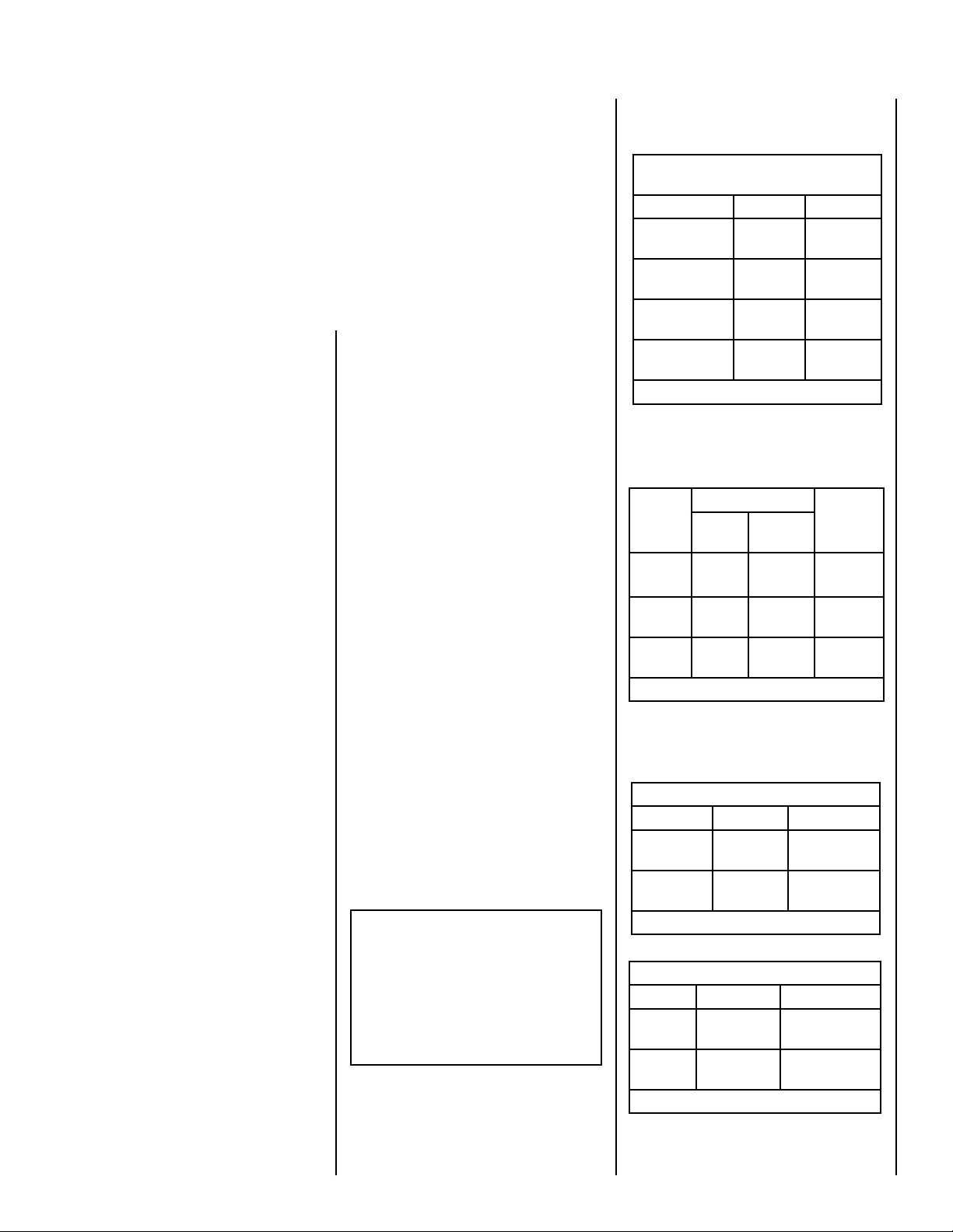
Input of millivolt models is variable. These rates
are shown in the following table:
Millivolt Models with
MAnnually-Modulated Gas Valves
Nat. Gas Propane
Model No. Input Rate
(BTU/HR)
EDVI25
EDVI30 21,500 to
EDVI35 25,500 to
Table 1
17,000 to
25,000
30,000
35,000
Input Rate
(BTU/HR)
19,000 to
25,000
22,000 to
28,000
26,000 to
34,000
Table 2 shows the units' gas orifice size for
the elevations indicated.
Model
No.
EDVI25
EDVI30 #37
EDVI35 #33
Table 2
Orifice Size Elevation
Nat.
Gas
#41
(.096”)
(.104”)
(.113”)
Prop.
Gas
#53
(.0595”)
1/16”
(.0625”)
#51
(.067”)
Feet
(meters)
0-4500
(0-1372)
0-4500
(0-1372)
0-4500
(0-1372)
Tables 3 and 4 show the gas pressure
requirements for all models:
Inlet Gas Supply Pressure (all models)
Fuel # Minimum Maximum
Natural Gas 4.5" WC
(1.12 kPa)
Propane 11.0" WC
(2.73 kPa)
Table 3
Manifold Gas Supply Pressure (all models)
Fuel # Low High
Natural
Gas
Propane (Lo) 6.3" WC
Table 4
(Lo) 1.6" WC
(.40 kPa)
(1.57 kPa)
10.5" WC
(2.61 kPa)
13.0" WC
(3.23 kPa)
(Hi) 3.5" WC
(.87 kPa)
(Hi) 10.0" WC
(2.49 kPa)
These vent systems must be routed through
the existing fireplace flue system to the vent
termination.
NOTE: DIAGRAMS & ILLUSTRATIONS ARE NOT TO SCALE
3
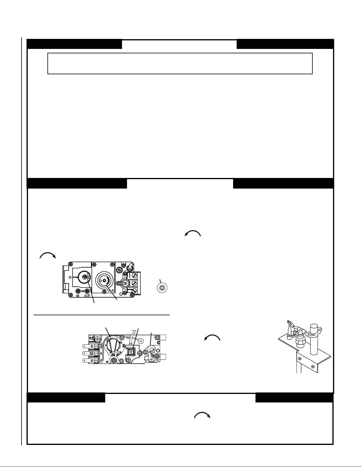
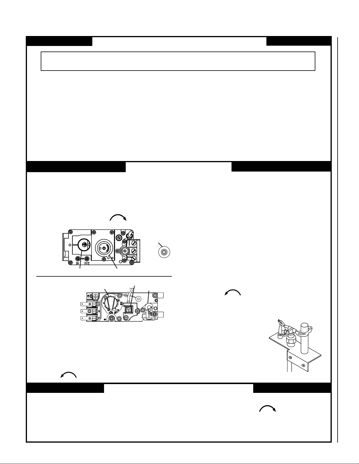
Page 4
Test gauge connections are provided on the
O
N
O
F
F
P
I
L
O
T
L
O
H
I
H
I
L
O
W
TPTH TP TH
P
I
L
O
T
P
I
L
O
T
O
N
it
O
F
F
IN
OUT
front of the millivolt gas control valve (identi
fied IN for the inlet and OUT for the manifold
side). See
Figures 1 & 2.
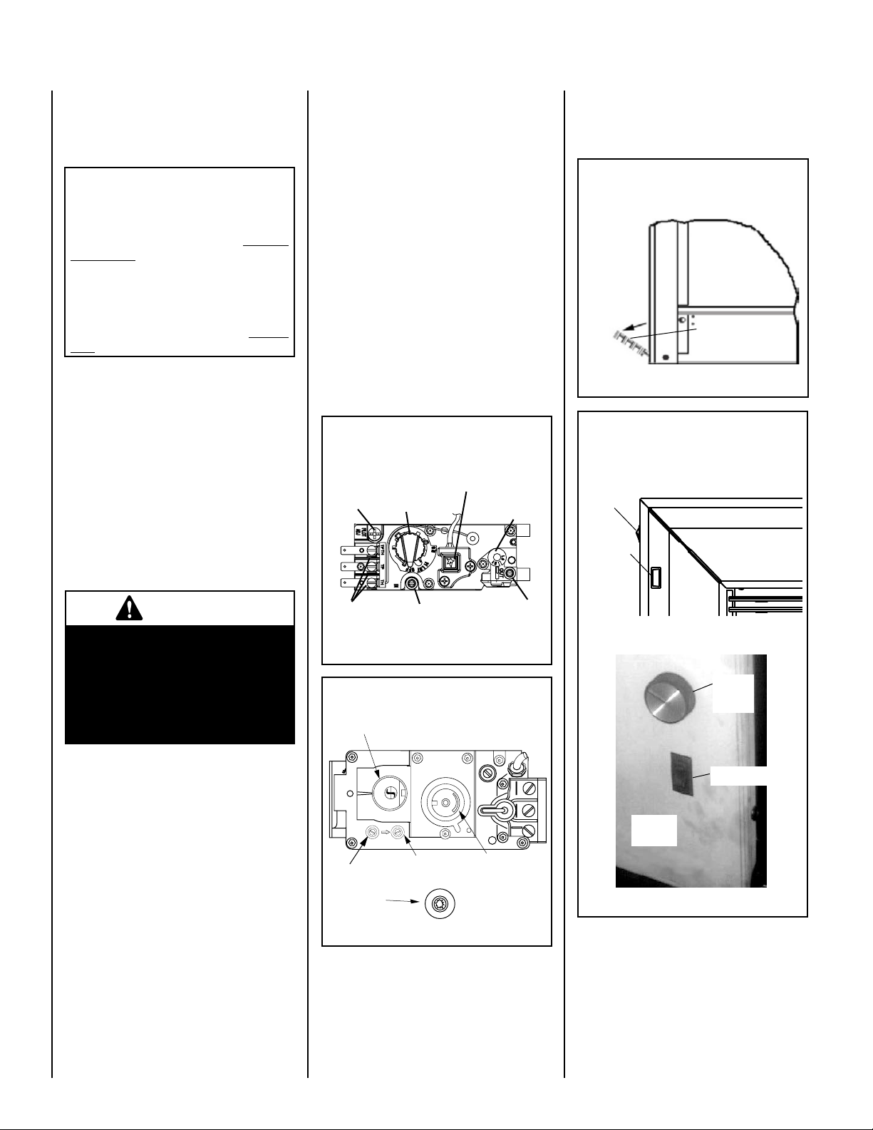
GAS CONTROLS
-
See Figure 3, showing how to access the
control compartment.
CONTROL COMPARTMENT ACCESS
Pull down hinged door to access control
compartment
(see Figure 3).
This appliance must be isolated from the
gas supply piping system (by closing its
individual manual shut-off valve) during
any pressure testing of the gas supply
piping system at test pressures
equal to
or less than 1/2 psig (3.5 kPa).
This appliance and its individual shut-off
valve
must be disconnected from the gas
supply piping system during any pressure
testing of that system at pressures
greater
than 1/2 psig (3.5 kPa).
This appliance must not be connected to a
chimney or flue serving a separate solid-fuel
appliance.
Burn-in Period
During the first few burns of these appliances
there will be some odor due to the curing of the
high temperature paint and burning off of lubri
cants used in the manufacturing process.
Depending on your use, the burn-in period may
take a few hours or a few days.
Do not turn on
blower during Burn-In period.
IMPORTANT
Keep your house well ventilated
during the curing process. The
odor and haze emitted by the
curing process can be quite
noticeable and may set off a
smoke detector.
These millivolt appliances are fitted with a burner
ON/OFF Switch, located on the side surround
panel as shown in
Figure 4 on Page 4. Once
the pilot is lit, and valve knob is in the ON posi
tion, the ON/OFF switch will control the appliance
ON/OFF operation. To operate, toggle the switch
between its ON and OFF positions.
Variable Flame Height Adjustment
These millivolt appliances are equipped with a
variable gas control valve. Flame height may be
adjusted through a range between fixed low and
high settings by rotating the HI/LO knob on the
valve (see Figures 1 & 2) alternately, while the
appliances are in operation.
MODELS: EDVI30 & EDVI35
Honeywell Millivolt Gas Valve Controls
PIEZO
CONVERTIBLE
INLET
PRESSURE
TAP
IGNITER
HI/LO REGULATOR
(adjusts flame height
and heat output)
PILOT
ADJUSTMENT
-
SCREW
TP/TH
TP
TH
WIRING
TERMINALS
GAS CONTROL
KNOB
Figure 1
MODEL EDVI25
SIT Millivolt Gas Valve Controls
GAS CONTROL
KNOB
OUTLET
PRESSURE
TAP
Control Compartment Access
Pull down hinged door to access control compartment
-
Side View of Insert
Pull down lower
louver (hinged)
Figure 3
Burner On/Off Switch and Rheostat Location
Burner On/Off
Switch
If optional surround is installed
Units with Beveled Surround
Rheostat
(blower
speed
control)
Left Front
surround
Panel
Units with Flat Surround
Rheostat
(blower
speed
control)
Lighting Millivolt Appliances
To light millivolt appliances refer to the detailed
lighting instructions found on
lish) and
lighting instructions may also be found on the
pull-out lighting instruction labels located in the
control compartment (below glass door).
4
Page 17 (French). Millivolt appliance
Page 16 (Eng-
INLET
PRESSURE
TAP
PIEZO
IGNITER
OUTLET
PRESSURE
TAP
CONVERTIBLE
HI/LO REGULATOR
(adjusts flame height
and heat output)
Figure 2
NOTE: DIAGRAMS & ILLUSTRATIONS ARE NOT TO SCALE
Figure 4
Left Front
surround
Panel
Burner On/Off
Switch
Page 5
OPERATION AND CARE OF YOUR
APPLIANCE
WARNING
IMPORTANT
Appliance operation may be controlled through
a remotely located optional wall thermostat or
remote control.
In lieu of remote control or remote wall thermo
stat operation, the appliance must be operated
directly through the on/off switch located on the
surround panel (see
If your millivolt appliance is equipped with an
optional wall thermostat kit or remote control
kit and the pilot is lit (and valve is in the On
position), the appliance main burner may be
turned on and off with the wall thermostat or
remote control.
Always keep the appliance area clear and free
from combustible materials, gasoline and other
flammable liquids.
Remember, Millivolt appliances have a continu
ous burning pilot flame. Exercise caution when
using products with combustible vapors.
Figure 4).
MAINTENANCE
The appliance and venting system should be
thoroughly inspected before initial use and at
least annually by a qualified service technician.
However, more frequent periodic inspections
and cleanings should be performed by the
homeowner. Homeowner must contact a quali
fied service technician at once if any abnormal
condition is observed.
Refer to the maintenance schedule on
7 for maintenance tasks, procedures, recommended frequency and by whom they should
be performed. Always verify proper operation
of the appliance after servicing.
Always turn off the gas to the appliance before
cleaning. Before re-lighting, refer to the lighting
instructions in this manual. Instructions are also
found on pull-out panels located below the glass
door in the control compartment.
Keep lower control compartment clean by
vacuuming or brushing at least twice a year.
More frequent cleaning may be required due to
excessive lint from carpeting, bedding materials,
etc. It is important that control compartments,
burners and circulating air passageways of the
appliance be kept clean.
Page
Turn off gas and electrical power
before servicing the appliance.
-
CAUTION
Wear gloves and safety glasses
for protection while doing
required maintenance.
IMPORTANT
Always verify proper operation
after servicing.
Check Burner Flame Appearance
-
Visually check the flame of the burner periodi
cally making sure the flames are steady and not
lifting or floating (see
Glass Cleaning
Note: Clean glass after first two weeks of operation (after Burn-In period is over).
The viewing glass should be cleaned periodi
cally to remove any build-ups caused from the
-
following:
• During start-up, it is normal for condensa
tion to form on the inside of the glass (this
condensation and fog will usually disappear
in a few minutes). This can cause lint, dust
and other airborne particles to cling to the
glass surface.
• Initial curing of the high temperature paint
and burning off of lubricants used in the
manufacturing process may result in a film
on the glass.
• A white coating may form on the glass as a
result of impurities and minerals in the fuel.
It is recommended that the glass be cleaned
two or three times during each heating season,
depending on the circumstances present.
Use one of the following to clean glass:
• Non-ammonia based household cleaner
• 50%-50% mix of white vinegar & water
• gas stove glass cleaner
Figure 19 on Page 8).
Do not use abrasive cleaners
on glass. Never clean the glass
when it is hot.
WARNING
Do not attempt to touch the front
enclosure glass with your hands
while the fireplace is in use.
Servicing Blower
Refer to blower wiring diagram on Page 13.
To access the blower assembly for maintenance, adjustment or replacement, see the
following procedure:
1. Unplug 120-volt A.C. power supply to
-
-
-
insert.
2. Shut off gas supply to insert.
3. Remove Glass Door (see
Removing Standard Glass Door Assembly
on
Page 8).
4. Remove log set, burner and grate.
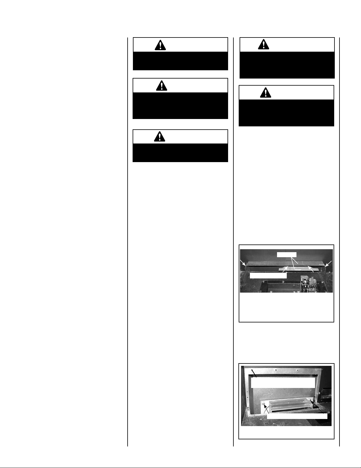
5. (EDVI25 only) Remove the two shields
shown in
Figure 5
6. (EDVI25 only) Remove blower access panel
(see
7. (EDVI25 only) Remove the two blower
mounting screws and remove the blower
(see
Figure 5.
Shields
Remove 4 Screws
Remove the 4 screws from back
wall (indicated by arrows).
EDVI25
Figure 6).
Figure 6).
Remove screws around parimeter of
blower access panel, then lift out.
Procedure For
NOTE: DIAGRAMS & ILLUSTRATIONS ARE NOT TO SCALE
Figure 6
Remove blower mounting screws.
EDVI25
5
Page 6
TH
TP
TP
TH
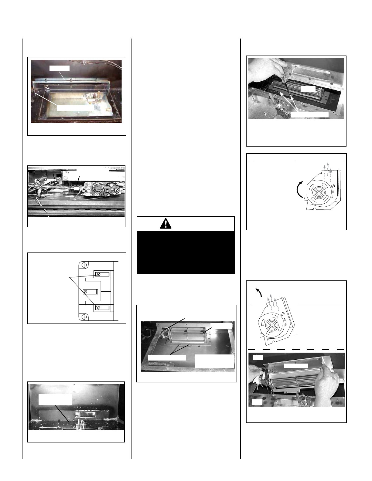
8. (EDVI30 only) Remove the two screws
shown in
Figure 7
Figure 7, then lift out air hood.
Air Hood
Remove 2 Screws
EDVI30
9. ENSURE THAT GAS SUPPLY IS SHUT OFF.
Disconnect gas line fitting at the valve (for
models EDVI30 & EDVI35). See
Disconnect Gas
Line Fitting
Figure 8.
Figure 8
Small Area Paint Touch-up
The finish of the insert body and surround
(optional) is a high-quality powdercoat. Only
use factory supplied powdercoat paint for
touch-ups, cat. no. 90L74.
Do not attempt to repaint the insert until the
finish is completely cured (see Burn-In Period
on this page). If the surface later becomes
stained or marred, it may be lightly sanded and
touched up with spray paint.
Paint is available at your local authorized Lennox
Hearth Products dealer. Never attempt to paint
a hot insert.
Inspect Wiring
Inspect and clean all wire connections. Ensure
that there is no melting or damage. Inspection
should include:
• Terminals at the valve
• On/Off switch
• Wall thermostat, remote control, or control
kit (optional parts)
Refer to wiring diagrams on Pages 13
& 14.
CAUTION
14. (EDVI35 only) Remove the blower per
instruction in
Disconnect wires from terminals on blower (including green
ground wire). Proceed to instructions in Figure 13.
Figures 12 through 14.
Blower
Remove 2 Screws
Figure 12 - EDVI35
Access Opening
Front
Rotate blower 45° clockwise toward the back,
then pull it forward so that
it is directly below the
blower access opening.
Rotate it so that the outlet
is again pointing upward.
Proceed to instructions in
Figure 14.
Blower - RH Side View
Outlet
Figure 13 - EDVI35
Back
10. Disconnect the two burner circuit wires
from the valve terminals (see
Disconnect Blue
Wires From Valve
Terminals
Figure 9).
Figure 9
11. (EDVI30 only) Remove the screws around
the perimeter of the gas valve train, then
lift out and set aside (see
Figure 11).
12. (EDVI35 only) Remove the screws around
the perimeter of the blower access panel,
then lift out and set aside (see
Remove Blower
Access Panel
Figure 10).
Label all wires prior to disconnection when servicing controls. Wiring errors can cause
improper and dangerous appliance operation.
13. (EDVI30 only) Remove the two blower
mounting screws and remove blower per
instructions in
Disconnect wires from terminals & green
ground wire after blower is pulled forward.
Remove 2 Screws
Figure 11
Figure 11.
EDVI30
Blower
To remove, tip blower
back, pull it forward,
then tip back upright.
14. (EDVI35 ONLY) When reinstalling the
blower (reverse steps in
Figures 12
through 14),
15. To reinstall blower, reverse steps 1-14.
Front
Rotate Blower 90°
counterclockwise,
while lifting blower up
at the same time. Lift
out as shown below.
Back
Blower Outlet
Front
Back
6
Figure 10
Figure 14 - EDVI35
EDVI35
NOTE: DIAGRAMS & ILLUSTRATIONS ARE NOT TO SCALE
Page 7

MAINTENANCE SCHEDULE
Annually (Before the onset of the Burning Season)
Maintenance Task Accomplishing Person Procedure
Inspecting/Cleaning Burner, Logs
and Controls
Check Flame Patterns and Flame
Height
Inspecting/Cleaning Pilot and Burner Qualified Service Technician Refer to
Checking Vent System Qualified Service Technician Inspect the vent system at the top and at the base (within the
Appliance Checkout Qualified Service Technician Perform the appropriate appliance checkout procedure detailed
Replacing Rockwool Ember Materials Homeowner/Qualified Service
Qualified Service Technician Inspect valve and ensure it is properly operating. Check piping
for leaks. Vacuum the control compartment, fireplace logs and
burner area.
Qualified Service Technician Refer to
and height displayed by the appliance conforms to the picture.
Flames must not impinge on the logs.
Remove any surface build-up on pilot and burner assembly.
Wipe the pilot nozzles, igniter/flame rod and hood. Ensure the
pilot flame engulfs the flame sensor as shown.
firebox) for signs of blockage or obstruction. Look for any signs
of dislocation of the vent components.
in this manual.
Remove old ember materials and vacuum the rockwool placement
Technician
area. Place new rockwool as described on Pages 11 & 12.
Figure 19 on Page 8 and verify the flame pattern
Figure 19 on Page 8 and Figure 38 on Page 13.
Periodically (After the Burning Season)
Maintenance Task Accomplishing Person Procedure
Cleaning Firebox Interior
Check Flame Patterns and Flame
Height
Checking Vent System
Cleaning Front Door Window
Homeowner Carefully remove logs, rockwool and and vermiculite. Vacuum out
interior of the firebox. Clean firebox walls and log grate. Replace
logs, Rockwool and vermiculite as detailed in this manual.
Homeowner Refer to
height displayed by the appliance conforms to the picture. Flames
must not impinge on the logs.
Homeowner Inspect the vent system at the top and at the base (within the
firebox) for signs of blockage or obstruction. Look for any signs
of dislocation of the vent components.
Homeowner Clean as necessary following the directions provided in this
manual. DO NOT TOUCH OR ATTEMPT TO CLEAN GLASS WHILE
HOT.
Figure 19 on Page 8 and verify the flame pattern and
NOTE: DIAGRAMS & ILLUSTRATIONS ARE NOT TO SCALE
7
Page 8
PROCEDURE FOR REMOVING THE STANDARD GLASS DOOR
ASSEMBLY
WARNING
Handle glass door with extreme care! The glass
door assembly is susceptible to damage. Do not
scratch while handling or while reinstalling.
WARNING
Never operate unit without the front glass door
panel in place and secure.
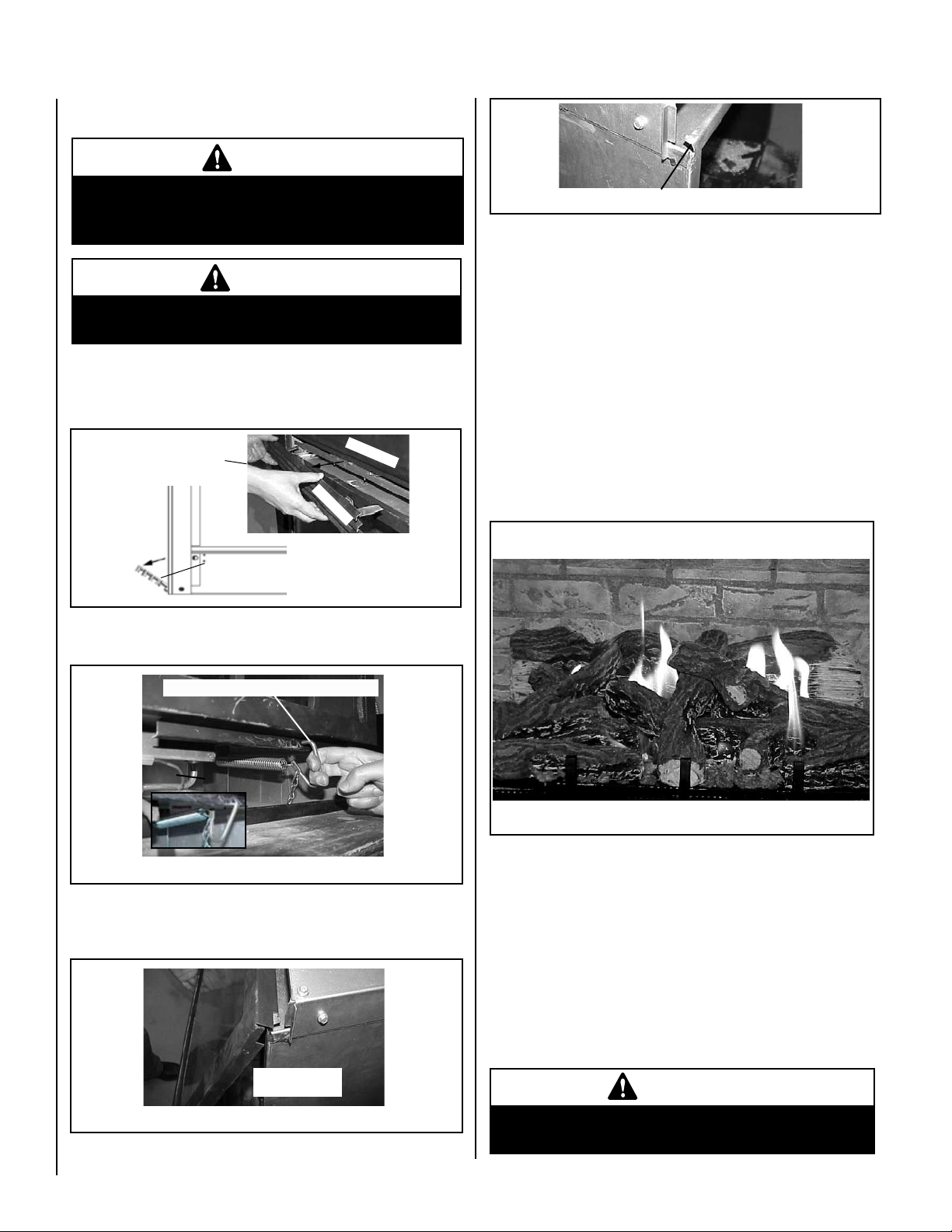
Remove the front door assembly from insert as follows:
1) Pull off top louver and hinge down lower louver (see
Pull Off
Top Louver
(side view)
Glass Front
Pull down lower louver (hinged)
Top Surround
Top Louver
2) Locate the spring hook under the glass door assembly (see
Pull hook forward until it releases out of the bottom door frame.
Figure 15).
Figure 15
Figure 16).
Figure 18
To reinstall glass door assembly panel, reverse instructions 1 - 3 on
this page.
Lift top of door off this flange
BURNER ADJUSTMENT
Flame Appearance and Sooting
Proper flame appearance is a flame which is blue at the base and becomes
yellow/orange in the body of the flame. When the insert is first lit, the
entire flame may be blue and will gradually turn yellow/orange during
the first 6-8 minutes of operation. If after 6-8 minutes the flame stays
blue, or if the flame is orange with evidence of sooting (black tip), the
air shutter may require adjustment.
An appliance operated with an air shutter opening that is too large will
exhibit flames that are blue and transparent. These weak, blue and
transparent flames are termed anemic. If the air shutter opening is too
small, sooting may develop.
Burner Flame Appearance
Pull door hook forward until it releases
Figure 16
3) Swing the bottom of the door outward (see
Door hook is located below glass door
Figures 17 & 18) and
lift it off of the flange on unit (where door hooks onto, at top). Set
door aside in a safe place.
Swing bottom of
door outward
Figure 17
8
NOTE: DIAGRAMS & ILLUSTRATIONS ARE NOT TO SCALE
Figure 19
EDVI35 Shown
Sooting is indicated by black puffs developing at the tips of very long
orange flames. Sooting results in black deposits forming on the logs,
appliance inside surfaces and on exterior surfaces adjacent to the
vent termination. Sooting is caused by incomplete combustion in the
flames and lack of combustion air entering the air shutter opening.
To achieve a warm yellow-to-orange flame that does not soot, the
shutter opening must be adjusted between these two extremes.
No smoke or soot should be present. Reposition the logs if flames
impinge on any of them. If the logs are properly positioned and
sooting conditions exist, the air shutter opening on the main burner
tube should be adjusted.
IMPORTANT
Ensure that the front glass panel is in place and
sealed during adjustment.
Page 9

Burner Adjustment Procedure
Adjustment Rod Up
(1/8" Open Position)
Air Shutter
Burner T
ube
Adjusting Set Screw
Adjustment Rod Down
(full open position)
CAUTION
WARNING
Air shutter adjustment should
only be performed by a qualified
professional service technician.
CAUTION
The adjustment rod and nearby
appliance surfaces are hot. Exercise caution to avoid injury while
adjusting flame appearance.
If the burner flame appearance differs greatly
from what is shown on this Page (see Burner
Flame Appearance), some adjustment from
the factory setting for the air shutter gap may
be necessary (to compensate for variables in
the installation and fuel such as, BTU value
composition, gas pressure, specific gravity
of gas, altitude, etc.).
Table 5 for Burner Air Shutter Adjust-
See
ment Guidelines.
Initially, always position the air shutter to the
factory setting as shown in
ment rod is located in the lower control area).
This can be done by moving the adjustment
rod up or down accordingly. Allow the burner
to operate for at least 15 minutes. Observe
the flame continuously. If it appears weak
or sooty as previously described, adjust the
air shutter to a more open position until the
proper flame appearance is achieved.
Figure 20 (adjust-
Carbon will be produced if the air shutter is closed too much. Any
damage due to carboning resulting from improperly setting the air
shutter is not covered under the warranty.
The following chart (Table 5) is provided to aid you in achieving the correct air shutter
adjustment for your installation.
Air Shutter Adjustment Guidelines
Amount of
Primary Air
If air shutter is
closed too far
If air shutter is open
Table 5
LOGS, VERMICULITE AND EMBERS - Models EDVI25 & EDVI30
(For EDVI35 Log Installation Instructions, see Page 11).
Installation Instructions
too far
Flame Color Air Shutter
Adjustment
Flame will be orange Air shutter gap should
be increased
Flame will be blue Air shutter gap should
be decreased
WARNING
If logs are not installed according to the directions shown here, flame
impingement and improper combustion could occur and result in soot
and/or excessive production of carbon monoxide (CO) - a colorless,
odorless, toxic gas.
Carefully install the seven-piece log set into the firebox as shown in these instructions. All
logs should fit onto corresponding pins and/or log stoppers. This will ensure a proper flame
and safe combustion.
Burner Air Shutter Adjustment
Ref. Air shutter Patent:
U.S. Pat. 5,553,603
FACTORY AIR SHUTTER OPENING SETTING
Model Gas Type Air Shutter Gap
EDVI25
EDVI30 Natural Gas
EDVI35 Natural Gas
Natural Gas
Propane
Propane
Propane
3/16” (4.76 mm)
3/8” (9.52 mm)
5/16” (7.94 mm)
1/2” (12.7 mm)
3/8” (9.52 mm)
1/2” (12.7 mm)
Figure 20
Note: Place some vermiculite around the burner as shown in Figure 30, if necessary, before
installing the logs (the entire bag of vermiculite will NOT be used).
Rear Log
Top Left Log
Front Center Log
Top Right Log
Center Log
Figure 21
NOTE: DIAGRAMS & ILLUSTRATIONS ARE NOT TO SCALE
Front Left Log
Front Right Log
9
Page 10

1. Place the rear log onto the two corresponding locating pins at the
back of the firebox as shown in Figure 22.
Figure 22
Rear Log
2. Place the Front Right Log onto the two corresponding locating pins
as shown in Figure 23.
Figure 23
Front Right Log
3. Place the Center Log onto the two corresponding locating pins
as shown in Figure 24.
Figure 25
Front Left Log
5. Install the Top Left Log onto the corresponding locating pin and
indentation on Center Log as shown in Figure 26.
Figure 26
Top Left Log
6. Install the Front Center Log over the Front Right Log . The front
of log will rest on the burner and the back of log will rest on rear log
as shown in
Figure 27.
Figure 24
Center Log
4. Place the Front Left Log onto the two corresponding locating pins
as shown in Figure 25.
10
NOTE: DIAGRAMS & ILLUSTRATIONS ARE NOT TO SCALE
Figure 27
Front Center Log
7. Install the Top Right Log into the corresponding indentations on
Front Center Log and Locating Pin as shown in Figure 28.
Page 11

Figure 29
Embers
Figure 28
8. Place the glowing embers on the burner as shown in Figure 29.
One package of ember material has been included with this log set
You will not need to use the entire bag.
IMPORTANT: The quantity and placement of the ember material can
affect insert performance therefore it is very important that it be placed
as shown in Figure 29.
a. Unpackage and divide the fine ember material (mineral wool) into
dime-sized fluffy pieces.
b. Distribute the pieces over the top of the front burner ports, filling the
area in front of the forward logs.
LOGS, VERMICULITE AND EMBERS - Model EDVI35
Center Left Log
Top Right Log
Rear Log
Figure 30
Vermiculite
Top Right Log
Front Right Log
Top Left Log
Figure 31
Front Left Log
Front Center Log
WARNING
If logs are not installed according to the directions shown here, flame impingement and improper combustion could occur and result in soot and/or excessive production of carbon monoxide (CO) - a colorless,
odorless, toxic gas.
11
Page 12

Carefully install the seven-piece log set into the firebox as shown in
these instructions. All logs should fit onto corresponding pins and/or
log stoppers. This will ensure a proper flame and safe combustion.
1. Place some vermiculite around the burner as shown in Figure 32
(the entire bag of vermiculite will NOT be used).
2. Place the Rear Log onto the two corresponding locating pins at
the back of the firebox as shown in
Figure 32.
Rear Log
5. Place the Front Center Log in place as shown in Figure 35. The
back of the log fits into the corresponding indent on Rear Log.
Figure 32
Vermiculite
3. Place the Front Right Log and the Center Left Log onto the two
corresponding locating pins (each) as shown in
Figure 33
Center Left Log
Front Right Log
Figure 33.
4. Place the Front Left Log onto the two corresponding locating pins,
then place the Top Left Log onto the locating pin on the Center Left
Log (the log will rest in the corresponding indent on Rear Log). See
Figure 34.
Top Left Log
Figure 35
Front Center Log
6. Install the Top Right Log into the corresponding indentations on
Front Center Log and Front Right Log as shown in
Figure 36
Top Right Log
Figure 36.
7. Place the glowing embers on the burner as shown in Figure 37.
One package of ember material has been included with this log set
You will not need to use the entire bag.
IMPORTANT: The quantity and placement of the ember material can
affect insert performance, therefore, it is very important that it be
placed as shown in Figure 37.
a. Unpackage and divide the fine ember material (mineral wool) into
dime-sized fluffy pieces.
b. Distribute the pieces over the top of the front burner area in front of
the forward logs (see
Figure 37).
12
Figure 34
Front Left Log
Figure 37
NOTE: DIAGRAMS & ILLUSTRATIONS ARE NOT TO SCALE
Embers
Page 13
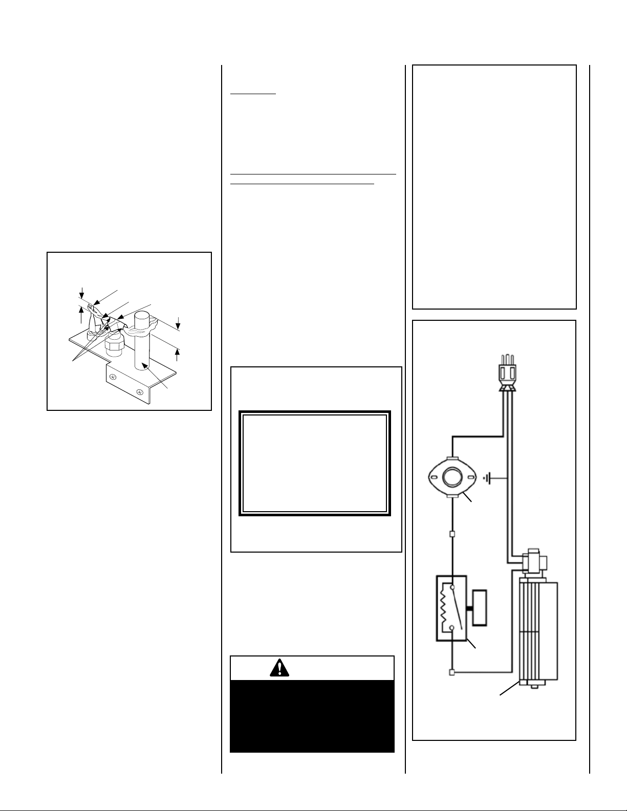
MILLIVOLT APPLIANCE CHECKOUT
¹⁄₈" Min
(3 mm)
Thermocouple
Igniter Rod
Hood
³⁄₈" Min
(9 mm)
Thermopile
Pilot
Nozzels
Light the pilot by following the instructions
Pages 16 or 17 of this manual.
The pilot flame should be steady, not lifting
or floating. Flame should be blue in color with
traces of orange at the outer edge. The top 3/8"
(10 mm) at the pilot generator (thermopile)
and the top 1/8" minimum (tip) of the quick
drop out thermocouple should be engulfed
in the pilot flame. The flame should project 1"
(25 mm) beyond the hood at all three ports
(Figure 38).
Replace logs if removed for pilot inspec
tion.
Proper Pilot Flame Appearance
FIREPLACE REQUIREMENTS
IMPORTANT: When installing these appliances
into a factory built fireplaces or heatforms, the
air flow within and around the fireplace shall not
be altered by the installation of the insert (i.e.
DO NOT BLOCK louvers or cooling air inlet or
outlet ports, circulating air chambers in a steel
fireplace liner or metal heat circulator).
CAUTION: The factory built firebox must
accept the insert without modification other
than removing bolted or screwed together
pieces such as smoke shelf/deflectors, ash lips,
screen or door tracks, log grates, refractory and
damper assemblies. Any fireplace component,
-
which is removed, must be retained so they
can be reinstalled to restore the fireplace to
its original operating condition. The removal
of any part must not alter the integrity of the
outer shell of the pre-engineered fireplace
cabinet in any way.
If any components are removed from (or altered)
from the existing fireplace, a Warning Label (see
Figure 39) must be affixed inside the fireplace
firebox, so that it shall be visible upon removal of
the fireplace insert. Note: RTV high temperature
silicone is an approved adhesive.
Room Air Circulation Blower
IMPORTANT: Blower ground wire with
power cord green wire should be attached
to the ground screw. Failure to do so will
result in a potential safety hazard. The
appliance must be electrically grounded
in accordance with local codes or, in
the absence of local codes, the National
Electrical Code, ANSI/NFPA 70 - latest
edition. (In Canada, the current CSA C22-1
Canadian Electrical Code - latest edition.
WARNING: THE POWER CORD MUST BE
PLUGGED DIRECTLY INTO A PROPERLY
GROUNDED THREE-PRONG 120 VOLT,
60 HZ WALL RECEPTACLE. DO NOT CUT
OR REMOVE THE GROUNDING PRONG
FROM THIS PLUG. DO NOT ROUTE
POWER CORD UNDER OR IN FRONT OF
APPLIANCE.
Blower Wiring Diagram
Figure 38
To light the burner, rotate the gas valve
control knob counterclockwise to the “ON”
position then turn “ON” the on/off switch To
light the burner, rotate the gas valve control
knob counterclockwise to the “ON” position
then turn “ON” the on/off switch mounted
on the surround assembly (see
Figure 4
on Page 4) or operate the burner with the
optional remote control, wall thermostat or
control switch.
With proper care and maintenance, your appliance will provide many years of enjoyment. If
you should experience any problem, first refer
to the troubleshooting guide in this manual. If
problem persists, contact your Lennox Hearth
Products Dealer.
BLOWER OPERATION
When the insert heats up, the blower will automat
ically be turned on by the fan disc located under
the firebox bottom on the front left side. It will
come on at the speed determined by the rheostat
located on the side surround panel (see Figure
4 on Page 4). To adjust the blower speed, dial
the rheostat to the desired speed setting. Rotate
the dial down (clockwise), just past the click (the
first ON position) for the highest speed setting.
Turning the knob further clockwise will provide
slower blower speeds. Note: If the rheostat is not
turned “on,” the blower will not operate.
Fireplace Warning Label
(Provided in Accessory Package)
WARNING
THIS FIREPLACE HAS BEEN ALTERED TO
ACCOMMODATE A FIREPLACE INSERT
AND SHOULD BE INSPECTED BY A QUALI-
FIED PERSON PRIOR TO RE-USE AS A
CONVENTIONAL FIREPLACE.
Figure 39
WIRING DIAGRAMS
Wiring diagrams are provided here for reference purposes only. This information is also
provided on schematics attached directly to the
appliance on a pullout panel located within the
control compartment.
-
CAUTION
Label all wires prior to disconnection when servicing controls. Wiring errors can cause
improper and dangerous appliance operation.
NOTE: DIAGRAMS & ILLUSTRATIONS ARE NOT TO SCALE
RedBlackBlack
Figure 40
Black
Fan Disc
Rheostat
Black
Hot (Live)
Green
(Ground)
Blower
Assembly
120 V AC
Power Cord
White
(Neutral)
13
Page 14

TH
TP
TH
TP
SIT & Honeywell
P
A
I
N
T
Millivolt Wiring Diagram
If any of the original wire as supplied must be
replaced, it must be replaced with Type AWM
105° C - 18 Gauge wire.
Thermopile
* Switch
* On/off Switch, Optional Thermostat or
Remote Control Receiver
Figure 41
ACCESSORY COMPONENTS
Tall Arch Pane Screen Door Kits
These decorative screen door panels fit on the
face of the appliance surround (eliminating the
need for the top and bottom louver panels).
Screen Door Kits
These decorative screen door panels fit over
the standard glass door panels.
Cat. No. Model Description
H1501 TPSDK-25 Twin-Pane Screen Door Kit, EDVI25
H0877 TPSDK-30DVI Twin-Pane Screen Door Kit, EDVI30
H0878 TPSDK-35I Twin-Pane Screen Door Kit, EDVI35
Brickaded Liner Kits
The brickaded liner kits include panels for the
rear and side walls of the firebox. The panels
have brick-like features in relief. These kits
can be retrofitted into previously installed
Elite™ inserts.
Deluxe Remote Control System
The Model RCL-T (Deluxe) Remote Control
System has all of the features of the standard
system along with an added easy to read LCD
screen which presents access to many enhance
ments, including; battery power level indicator,
timer, mode of operation, thermostatic display
including room temperature in either metric
or English units, flame indicator and clock.
Fully programmable, the Model RCL-T allows
for command over nearly all operational and
temperature variables, using the hand held
remote control transmitter.
Cat. No. Model Description
H0251 RCL-T Remote Control System (Deluxe)
Standard Remote Control System
-
The Model RCL (Standard) Remote Control
System, features a simple On/Off control
function for the insert. This model includes a
hand-held transmitter, a remote receiver with
wall-mount coverplate and all hardware required
to install the unit. The remote receiver can be
wall or hearth mounted.
EDVI35 Brick Liner Kit Shown
Cat. No. Model Description
H0904 BLK-30DVI Brick Liner Kit, EDVI30
H0905 BLK-35DVI Brick Liner Kit, EDVI35
H1513 BLK-25DVI Brick Liner Kit, EDVI25
CAT# MODEL# DESCRIPTION
H3595 TAPSDK25C 25” Charcoal, EDVI25
H3596 TAPSDK25TI 25” Textured Iron, EDVI25
H3597 TAPSDK25SP 25” Satin Pewter, EDVI25
H3840 TAPSDK25PC 25” Pewt/Charc, EDVI25
H3598 TAPSDK30C 30” Charcoal, EDVI30
H3599 TAPSDK30TI 30” Textured Iron, EDVI30
H3600 TAPSDK30SP 30” Satin Pewter, EDVI30
H3841 TAPSDK30PC 30” Pewt/Charc, EDVI30
H3601 TAPSDK35C 35” Charcoal, EDVI35
H3602 TAPSDK35TI 35” Textured Iron, EDVI35
H3603 TAPSDK35TSP 35” Satin Pewter, EDVI35
H3842 TAPSDK35TPC 35” Pewt/Charc, EDVI35
Control Kit
If an optional surround kit is not purchased,
this kit is required to provide the on/off switch
and rheostat.
Cat. No. Model Description
H0249 RCL Remote Control System (Standard)
Touch-Up Powdercoat Paint Kit
Repair of minor scratches and
discoloration of the appliance's
charcoal powdercoated sur
faces may be accomplished
with the use of this touch-up
14
Cat. No. Model Description
H0919 CK-EI Control Kit, Elite Inserts
NOTE: DIAGRAMS & ILLUSTRATIONS ARE NOT TO SCALE
paint kit.
Cat. No. Model Description
90L74 TPK-C Touch-Up Powdercoat Paint Kit
Page 15

ACCESSORY COMPONENTS
Surround Kits
Hearth Riser Kits
Wall Thermostat
The wall thermostat kit provides temperature
control for optimum comfort.
H4635 DWTK Wall Thermostat Kit, Digital
Decorative Flat Louver Kits
These decorative trim accents, installl above and
below the glass door. They are available in three
different finishes to enhance the beauty of the
insert and are sure to fit into any decor.
Cat. No. Model Description
H0886 FLK-30DVI Flat Louver Kit, Charcoal, EDVI30
H0887 FLK-30DVIG Flat Louver Kit, Gold, EDVI30
H0888 FLK-30DVIBS Flat Louver Kit, Brushed Stainless, EDVI30
H0889 FLK-35 Flat Louver Kit, Charcoal, EDVI35
H0890 FLK-35G Flat Louver Kit, Gold, EDVI35
H0891 FLK-35BS Flat Louver Kit, Brushed Stainless, EDVI35
H1505 FLK-25 Flat Louver Kit, Charcoal, EDVI25
H1506 FLK-25G Flat Louver Kit, Gold, EDVI25
H1507 FLK-25BS Flat Louver Kit, Brushed Stainless, EDVI25
These surround panels install around the insert
body providing an attractive finished look.
Width
SKS-25 = 41 1/16" W X 26 1/16" H
SKM-25 = 44 1/8" W X 27 5/8" H
SKS-30 = 40 1/4" W x 27 1/2" H
SKM-30 = 45 3/4" W x 30 1/4" H
SKL-30 = 49 1/4"" W x 30" H
SKM-35 = 48 1/16" W x 34 1/16" H
Cat. No. Model Description
H0881 SKS-30 Beveled Surround, Sm, EDVI30
H0882 SKM-30 Beveled Surround, Med, EDVI30
H0883 SKL-30 Beveled Surround, Lg, EDVI30
H0884 SKM-35 Beveled Surround, Med, EDVI35
H1503 SKS-25 Beveled Surround, Sm, EDVI25
H1504 SKM-25 Beveled Surround, Med, EDVI25
SIZES
Height
Flat Surround Kits
These flat surround kits are designed to have
the outside overall dimensions cut down
when custom shaped surround trim panels
are needed.
Cat. No Model Description
H3389 EFS-E35I Elite Insert Flat Surround Kit, E35I
H3390 EFS-E30I Elite Insert Flat Surround Kit, E30I
H3391 EFS-E25I Elite Insert Flat Surround Kit, E25I
The hearth riser trim kits are designed to be
used with the optional surround kits (sold
separately). It provides a finished look below
the insert face when installed into fireplaces
with a elevated firebox.
Surround
Insert
Hearth Riser Trim Panel
Panels are available in 1”, 3” & 6” heights
Cat. No. Model Description
EDVI25
H2042 HRKS1-25 Hearth Riser Kit, SM, E25I, 1”
H2043 HRKS3-25 Hearth Riser Kit,, SM, E25I, 3”
H2044 HRKS6-25 Hearth Riser Kit, SM, E25I, 6”
H2045 HRKM1-25 Hearth Riser Kit, MED, E25I, 1”
H2046 HRKM3-25 Hearth Riser Kit, MED, E25I, 3”
H2047 HRKM6-25 Hearth Riser Kit, MED, E25I, 6”
EDVI30
H2098
HRKS1-30 Hearth Riser Kit, SM, E30I, 1”
H2099
HRKS3-30 Hearth Riser Kit, SM, E30I, 3”
H2100
HRKS6-30 Hearth Riser Kit, SM, E30I, 6”
H2101
HRKM1-30 Hearth Riser Kit, MED, E30I, 1”
H2102
HRKM3-30 Hearth Riser Kit, MED, E30I, 3”
H2103
HRKM6-30 Hearth Riser Kit, MED, E30I, 6”
H2104
HRKL1-30 Hearth Riser Kit, LG, E30I, 1”
H2105
HRKL3-30 Hearth Riser Kit, LG, E30I, 3”
H2106
HRKL6-30 Hearth Riser Kit, LG, E30I, 6”
EDVI35
H2107
HRKM1-35 Hearth Riser Kit, MED, E30I, 1”
H2108
HRKM3-35 Hearth Riser Kit, MED, E30I, 3”
H2109
HRKM6-35 Hearth Riser Kit, MED, E30I, 6”
SM = used with small surround
MED = used with medium surround
LG = used with large surround
NOTE: DIAGRAMS & ILLUSTRATIONS ARE NOT TO SCALE
15
Page 16
H
I
L
O
W
TPTH TP TH
P
I
L
O
T
P
I
L
O
T
O
N
it
O
F
F
OUT
IN
LIGHTING INSTRUCTIONS – MILLIVOLT GAS VALVE
O
N
O
F
F
P
I
L
O
T
L
O
H
I
FOR YOUR SAFETY, READ BEFORE LIGHTING
WARNING: IF YOU DO NOT FOLLOW THESE INSTRUCTIONS EXACTLY, A FIRE OR EXPLOSION
MAY RESULT CAUSING PROPERTY DAMAGE, PERSONAL INJURY OR LOSS OF LIFE.
A. This appliance has a pilot which must be lighted with a piezo
igniter. When lighting the pilot, follow these instructions
exactly.
B. BEFORE OPERATING, smell all around the appliance area for
gas. Be sure to smell next to the floor because some gas is
heavier than air and will settle on the floor.
WHAT TO DO IF YOU SMELL GAS
• Extinguish any open flame.
• Open windows.
• Do not light any appliance.
• Do not touch any electrical switches.
LIGHTING INSTRUCTIONS
1. STOP! Read the safety information above on this page.
2. Access the lower control compartment.
3. Turn remote wall switch to “OFF.”
4. Verify main line shut-off valve is open.
5. Push in gas control knob slightly and turn clockwise
to “OFF.”
PIEZO
TH
SIT Millivolt
Gas Valve
Honeywell Millivolt
Gas Valve
TP/TH
TP
TH
GAS CONTROL
KNOB
GAS CONTROL
KNOB
- LO/HI +
PIEZO
IGNITER
IGNITER
TP
TP/TH
- LO/HI +
• Do not use any phone in your building.
• Immediately call your gas supplier from a neighbor’s
phone.
• If your gas supplier cannot be reached, call the fire depart-
ment.
C. Use only your hand to push in or turn the gas control knob.
Never use tools. If the knob will not push in or turn by hand,
do not try to repair it, call a qualified service technician. Force
or attempted repair may result in a fire or an explosion.
D. Do not use this appliance if any part has been under water.
Immediately call a qualified service technician to inspect the
appliance and to replace any part of the control system and
any gas control which has been under water.
6. Wait five (5) minutes to clear out any gas. If you then smell gas,
STOP! Follow “B” in the safety information above on this page. If you
do not smell gas, go to the next step.
7. Push in gas control knob slightly and turn counterclockwise
to “PILOT.”
8. Push in control knob all the way and hold in. Immediately light the
pilot by triggering the spark igniter (pushing the button) until pilot
lights. Continue to hold the control knob in for about 1-1/2 minutes
after the pilot is lit. Release knob and it will pop back up. Pilot should
remain lit. If it goes out, repeat steps 5 through 8.
• If knob does not pop up when released, stop
and immediately call your service technician
or gas supplier.
• If pilot will not stay lit after several tries,
turn the control knob to “OFF” and call
your service technician or gas supplier.
Millivolt Pilot
9. Turn gas control knob counterclockwise
to “ON.”
10. Close lower control compartment.
Note: Knob cannot be turned from “PILOT” to “OFF”
unless the knob is pushed in slightly. Do not force.
1. Turn remote wall switch “OFF.” The pilot will remain lit for
normal service.
2. For complete shutdown, turn remote wall switch to “OFF.”
16
3. Access the lower control compartment.
TO TURN OFF GAS TO APPLIANCE
4. Depress gas control knob slightly and turn clockwise
to “OFF.” Do not force.
5. Close lower control compartment.
Page 17
INSTRUCTIONS D’ALLUMAGE – VANNE GAZ MILLIVOLT
O
N
O
F
F
P
I
L
O
T
L
O
H
I
H
I
L
O
W
TPTH TP TH
P
I
L
O
T
P
I
L
O
T
O
N
it
O
F
F
OUT
IN
POUR VOTRE SÉCURITÉ, LISEZ CES INSTRUCTIONS AVANT L’ALLUMAGE
AVERTISSEMENT : SI VOUS NE SUIVEZ PAS CES INSTRUCTIONS À LA LETTRE, IL POURRAIT S’EN SUIVRE UN INCENDIE OU
UNE EXPLOSION CAUSANT DES DOMMAGES MATÉRIELS, DES BLESSURES CORPORELLES OU MÊME DES PERTES DE VIE.
A. Cet appareil est muni d’une veilleuse qui doit être allumée avec un
allumeur piézo-électrique. Lorsque vous allumez la veilleuse, suivre
exactement ces instructions.
B. AVANT L’ALLUMAGE: Assurez-vous que vous ne détectez aucune odeur
de gaz autour de l’apareil ainsi que près du sol; certains gaz, étant plus
lourds que l’air, descendent au niveau du sol.
VOICI CE QUE VOUS DEVEZ FAIRE SI VOUS DÉCELEZ UNE ODEUR
DE GAZ:
• Éteignez toute flamme visible.
• Ouvrez les fenêtres.
• N’allumez aucun appareil.
• Ne touchez à aucun commutateur électrique.
• Ne vous servez d’aucun téléphone dans votre édifice.
INSTRUCTIONS D'ALLUMAGE
1. ARRÊTEZ! Lisez les consignes de sécurité au verso de cette plaque.
2. Ouvrez le compartiment de contrôle du bas.
3. Tournez l’interrupteur mural à la position d’arrêt “OFF”.
4. Assurez-vous que la soupape d’arrêt de la canalisation principale est
ouverte.
5. Enfoncez légèrement le bouton de réglage du gaz et tournez-le dans
le sens des aiguilles d’une montre jusqu’à la position
d’arrêt “OFF”.
ALLUMEUR
SIT Vanne
Gaz Millivolt
BOUTON DE RÉGLAGE DU GAZ
BOUTON DE RÉGLAGE DU GAZ
- LO/HI + (COMMANDE
DE TAILLE DE FLAMME)
ALLUMEUR
Honeywell Vanne
Gaz Millivolt
Remarque: Il est impossible de tourner le bouton de “PILOT” à “OFF” à
moins qu’il ne soit légèrement enfoncé. Ne le forcez pas.
6. Attendez cinq (5) minutes pour l’evacuation du gaz. Si vous décelez
une odeur de gaz, ARRÊTEZ ! Retournez au point “B” des consignes
de sécurité au verso de cette plaque. Si vous ne remarquez aucune
odeur de gaz, passez à l’étape suivante.
7. Enfoncez légèrement le bouton de réglage du gaz et tournez-le en
sens inverse des aiguilles d’une montre jusqu’à la position de veil
leuse “PILOT”.
TP/TH
TP
TH
TH
TP
TP/TH
- LO/HI + (COMMANDE
DE TAILLE DE FLAMME)
-
• Appelez immédiatement votre compagnie de gaz en utilisant le télé-
phone du voisin.
• S’il vous est impossible de contacter votre compagnie de gaz, appelez
le service des incendies.
C. N’utilisez que votre main pour manipuler le bouton de réglage du gaz.
N’utilisez jamais d’outils. Si le bouton refuse de tourner ou de bouger,
n’essayez pas de le réparer. Communiquez immédiatement avec un
technicien de service qualifié. Toute tentative pour le forcer ou le
réparer, risquerait de provoquer un incendie ou une explosion.
D. Ne vous servez pas de cet appareil si l’un de ses éléments a été
immergé dans l’eau. Appelez immédiatement un technicien compétent
pour faire inspecter l’appareil et remplacer toute pièce du système de
réglage ou commande du gaz qui a été sous l’eau.
8. Enfoncez le bouton de réglage jusqu’au fond et gardez-le enfoncé.
Allumez immédiatement la veilleuse en déclenchant l’allume-gaz
à étincelle (en poussant le bouton) jusqu’à ce que la veilleuse
s’enflamme. Continuez de tenir le bouton de réglage enfoncé
pendant environ 90 secondes après l’allumage de la veilleuse.
Relâchez le bouton et il sortira subitement. La veilleuse devrait
rester allumée. Si elle s’éteint, répétez les étapes 5 à 8 inclusive
-
ment.
• Si le bouton ne sort pas automatiquement après avoir été relâché,
arrêtez immédiatement et téléphonez à votre technicien de service
ou à votre fournisseur de gaz.
• Si la veilleuse refuse de rester allumée après plusieurs tentatives,
tournez le bouton de réglage jusqu’à sa position d’arrêt “OFF” et
téléphonez à votre technicien de service ou à votre fournisseur de
gaz.
9. Tournez le bouton de réglage du gaz en sens inverse des aiguilles
d’une montre jusqu’à sa position de marche “ON”.
10. Fermez le compartiment de contrôle du bas.
11. Au besoin, rebrancher l’appareil au
courant électrique et remettre
Millivolt Pilot
l’interrupteur du brûleur principal
à la position “ON” ou régler le
0thermostat à la température désirée.
12. Si l’appareil ne fonctionne pas,
suivre les instructions intitulées
“Pour fermer le gaz qui alimente
l’appareil” et appeler un technicien
ou le fournisseur de gaz.
POUR FERMER LE GAZ QUI ALIMENTE L’APPAREIL
1. Tournez l’interrupteur mural à la position d’arrêt “OFF”. La veilleuse
restera allumée jusqu’au retour du service normal.
2. Pour une fermeture complète, tournez l’interrupteur mural à la posi
tion d’arrêt “OFF”.
3. Ouvrez le compartiment de contrôle du bas.
4. Enfoncez légèrement le bouton de réglage du gaz et tournez-le dans
le sens des aiguilles d’une montre jusqu’à la position
-
d’arrêt “OFF”. Ne forcez pas le bouton.
5. Fermez le compartiment de contrôle du bas.
17
Page 18

REPLACEMENT PARTS LIST
Item # Part/Cat. No. Description Where Used
1 67L70 Pilot Assembly, NG/LP All
2 67L68 Pilot Tube All
3 67L67 Thermocouple All
4 60J79 Thermopile (pilot generator) All
10a 10K86 Piezo Igniter (wire not included) EDVI25
10b 24M89 Piezo Igniter (wire included) EDVI30 & EDVI35
7 67L87 Electrode Cable (piezo igniter wire w/ electrode) All
5a H1657 Gas Valve, NG – SIT EDVI25
5b H6196 Gas Valve, NG – Honeywell EDVI30 & EDVI35
6 H1127 Burner Assembly NG/LP EDVI25 & EDVI30
6 H1160 Burner Assembly NG/LP EDVI35
8 93L32 Connector-Flex Gas ALL
9 21L79 Orifice, Burner, NG (.#41) EDVI25
9 24M10 Orifice, Burner, NG (.#37) EDVI30
9 99K77 Orifice, Burner, NG (#33) EDVI35
9 39L10 Orifice, Burner, LP (#53) EDVI25
9 21L01 Orifice, Burner, LP (.0625) EDVI30
9 H0922 Orifice, Burner, LP (#51) EDVI35
11 H1585 Door Kit, Complete EDVI25
11 H0923 Door Kit, Complete EDVI30
11 H0924 Door Kit, Complete EDVI35
23
24 H6236
12 H0928
13 H0927 Grate Assembly EDVI35
14 H0929 Lock Assembly, Door (w/spring) All
15 27K30 Switch, On/Off All
16 88L53 FGE Glowing Embers All
17 H6235 Log Set, 7 pc. EDVI25 & EDVI30
17 H1103 Log Set, 7 pc. EDVI35
18 H3696 Vermiculite, Bag All
19 H1391 Blower Assembly, 7” EDVI25
19 H1141 Blower Assembly, 9" EDVI30 & EDVI35
20
21a H1290
21b 527
22 13M23 Switch, Temp. Control (TOD) All
18
Gas Controls
Misc. Gas Components
H0920
H0921
H1576 GCKNL-E25I, Conversion Kit, NG to LP EDVI25
GCKNL-E30I, Conversion Kit, NG to LP EDVI30
GCKNL-E35I, Conversion Kit, NG to LP EDVI35
Miscellaneous Parts
H1393 Gasket, Flue Adapter EDVI25
Gasket, Flue Adapter EDVI30 & EDVI35
Grate Assembly EDVI25 & EDVI30
Log Sets
Room Air Blower System
H1157 Power Cord All
Rheostat (knob included) All
Knob, Rheostat All
Page 19
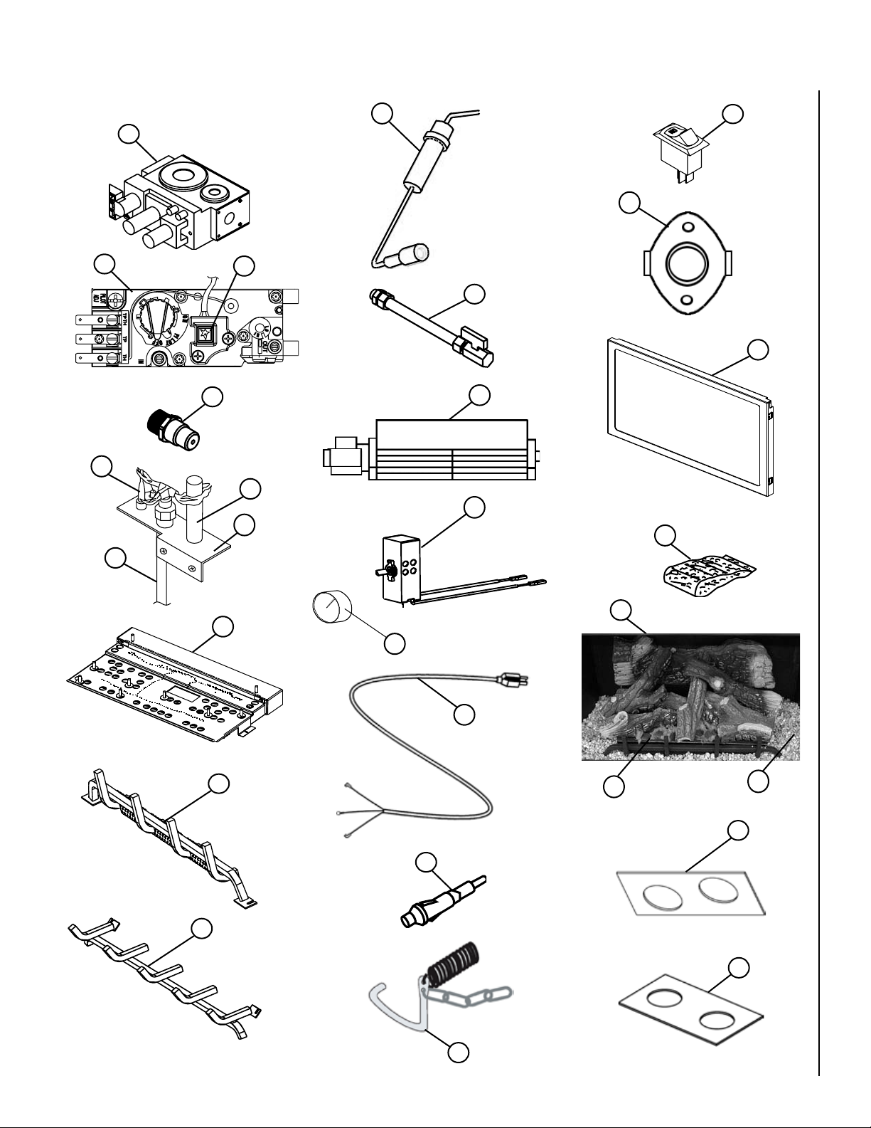
REPLACEMENT PARTS DIAGRAMS
O
N
O
F
F
P
I
L
O
T
L
O
H
I
5a
7
15
22
5b
10b
8
11
9
3
3
19
4
21a
1
16
2
17
6
21b
20
12
16
18
23
10a
13
24
NOTE: DIAGRAMS & ILLUSTRATIONS ARE NOT TO SCALE
14
19
Page 20
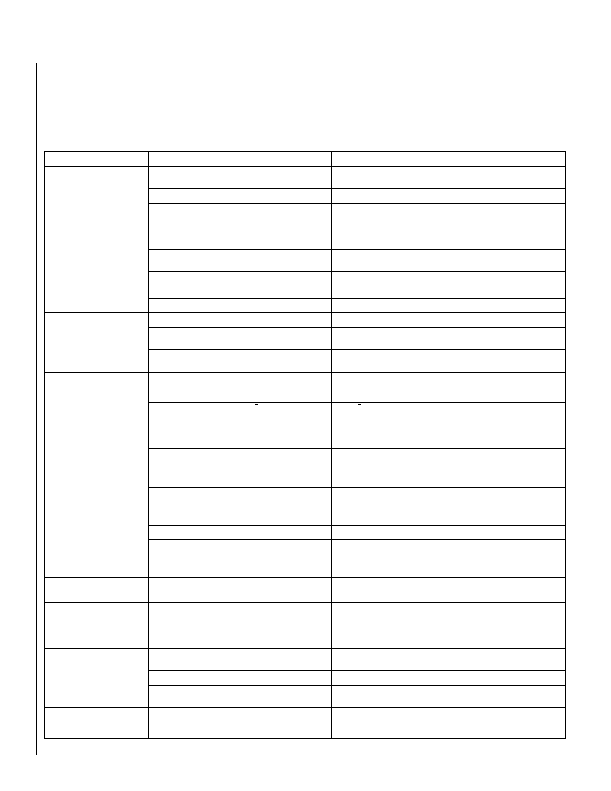
TROUBLESHOOTING THE MILLIVOLT GAS CONTROL SYSTEM
Note: Before troubleshooting the gas control system, be sure external gas shut off valve (located at gas supply inlet) is
in the “ON” position.
Important: Valve system troubleshooting should only be accomplished by a qualified service technician.
SYMPTOM POSSIBLE CAUSES CORRECTIVE ACTION
1) Spark igniter will not light
pilot after repeated triggering of
igniter button.
WARNING: IF THE PILOT WILL
NOT LIGHT AFTER ONE MINUTE
OF ATTEMPTING, WAIT FOR AT
LEAST FIVE MINUTES FOR GAS
TO CLEAR BEFORE ATTEMPTING
AGAIN.
2) Pilot will not stay lit after
carefully following the lighting
instructions.
3) Pilot flame stays lit, but
main burner will not light. (Valve
pilot/on/off knob is in ON position,
on/off switch, wall thermostat or
remote control is set to ON).
Read important note below.
IMPORTANT NOTE: If an
optional Remote Switch*
is used for burner operation and if the standard
burner OFF/ON switch is
still installed on appliance, it must be in the
"OFF" position.
4) Frequent pilot/burner outage
problem
5) Smell of gas A. Pilot, gas supply system, or pilot & burner adjustment
6) A thin coating of black soot
forms on the window. NOTE: See
Page 5, Glass Cleaning.
7) A white coating forms on
windows, logs, and/or inside
walls of firebox.
*Optional Remote Switch kits: wall switch, wall thermostat or remote control.
20
A. Electrode wire (at Piezo Igniter) not pushed completely
on.
B. Piezo igniter is defective • Replace piezo igniter
C. Defective or misaligned electrode at pilot (spark at
electrode)
D. Incorrect lighting procedure • Carefully follow the lighting instructions on Pages 16 &17 or as found in
E. Gas supply problem • Check for multiple gas shut-offs. Check gas supply lines.· Check inlet gas
F. Pilot orifice plugged • Clean or replace pilot orifice
A. Thermocouple is not firmly connected to control valve • Check connection at valve
B. Pilot flame is not directed to top of thermocouple • Ensure thermocouple is fully inserted into pilot assembly. Clean and/or adjust
C. Thermocouple is defective. The millivolt production should
be a minimum of 14 MV with pilot only.
A. Burner control switch (on/off switch, wall thermostat or
remote control) is in “OFF” position; or thermostat (if installed)
is set to a temperature setting that is too low.
B. Electrical wiring is damaged or poorly connected or
remote switch is defective.
C. One of the following components may be defective:
burner control switch, thermostat or thermopile. Thermopile:
Millivolt production should be a minimum of 325 MV with
pilot only.
D. Thermopile may not be generating sufficient mil-
livolts
E. Plugged burner orifice heck burner orifice for blockage and remove.
F. OFF/ON Switch & Remote Switch* are in the "ON"
position resulting in excessive resistance
A. Pilot flame may be too low or blowing (high) causing the
pilot/valve safety to drop out.
screws on valve may be leaking. FOLLOW INSTRUCTIONS
ON THE COVER OF THIS MANUAL
A. Burner primary air inlet is restricted or blocked • Ensure all openings (fresh air inlets) in the insert are free from dust and
B. Flames make contact with logs or other surfaces • Ensure ceramic logs are in their correct positions.
C. Improper venting • Check for flue blockage, disconnected flue, improper installation. Make
A. Residues/impurities being burned off or impurities in the
fuel
• Check connection
• Using a match, light pilot. If pilot lights, turn off pilot and trigger the igniter
button again. If pilot lights, an improper gas mixture caused the bad lighting
and a longer purge period is recommended. If pilot will not light – check gap at
electrode and pilot – It should be between 1/8” and 3/16.” If the gap is out of this
range, adjust the gap or replace the pilot assembly. (
the insert control compartment.
pressure. It should be within the limits as marked on the rating plate.
pilot for maximum flame impingement on thermocouple if necessary.
• Replace thermocouple
• Turn burner on/off switch on and/or refer to instructions provided with
optional thermostat or remote control, if applicable.
• Check wall switch and wires for proper connections. Refer to Millivolt Wiring
Diagram (
switch, if the burner comes on, replace the defective wall switch. If okay, jumper
the wires across the wall switch wires at the valve. If the burner comes on,
wires are faulty or connections are bad.
• Refer to Millivolt Wiring Diagram (Page 14, Figure 41). Electrically bypass
components one at a time and replace defective item.
• Check thermopile with millivolt meter. Take reading at thermopile ter
minals of gas valve. It should read 325 millivolts minimum with optional
wall switch “OFF.” Replace faulty thermopile if reading is below specified
minimum.
When turning on the burner using a Remote Switch,* ensure that the
standard OFF/ON Switch is in the "OFF" position. If both switches are in
the ON position, it may result in excessive resistance (& millivolt drainage)
and the burner may not come on.
• Clean and/or adjust pilot flame for maximum flame impingement on ther
mocouple (Page 13, Figure 38).
• WARNING: NEVER USE AN OPEN FLAME TO CHECK FOR LEAKS.
After the gas company or fire department has given clearance to re-enter the
dwelling, have a qualified technician test all gas joints from the gas meter to
the gas heater regulator for leaks using a gas leak test solution (also referred
to as bubble leak solution).
debris. Recheck these areas periodically.
appropriate corrections.
• Follow cleaning guidelines outlined in the MAINTENANCE section of this
manual.
Page 14, Figure 41). Jump the wire across terminals at the wall
Page 13, Figure 38)
-
-
Page 21

NOTES:
THIS PAGE LEFT BLANK INTENTIONALLY
21
Page 22

NOTES:
22
THIS PAGE LEFT BLANK INTENTIONALLY
Page 23

NOTES:
THIS PAGE LEFT BLANK INTENTIONALLY
23
Page 24
WARRANTY
Your gas appliance is covered by a limited warranty (see warranty
certificate provided with appliance). Please read the warranty to be
familiar with its coverage.
Retain this manual. File it with your other documents for future refer
ence.
PRODUCT REFERENCE INFORMATION
We recommend that you record the following important information about
your fireplace. Please contact your Lennox dealer for any questions or
concerns. For the number of your nearest Lennox dealer, please call
1-800-9-LENNOX.
REPLACEMENT PARTS
See Pages 18 and 19 for a complete replacement parts list. Use only
parts supplied from the manufacturer.
Your Fireplace Insert's Model Number ___________________________________
Your Fireplace Insert’s Serial Number ___________________________________
The Date On Which Your Fireplace Insert Was Installed ______________________
Normally, all parts should be ordered through your Lennox distributor or
dealer. Parts will be shipped at prevailing prices at time of order.
When ordering repair parts, always give the following information:
1. The model number of the appliance.
2. The serial number of the appliance.
-
3. The part number.
4. The description of the part.
5. The quantity required.
6. The installation date of the appliance.
If you encounter any problems or have any questions concerning the
installation or application of this system, please contact your dealer.
LENNOX HEARTH PRODUCTS
1110 West Taft
Orange, CA 92865
visit us at www.Lennox.com
The Type of Gas Your Fireplace Insert Uses _______________________________
Your Dealer's Name _________________________________________________
Fuel Type (Check one) c Natural Gas c Propane Gas (LP)
Lennox reserves the right to make changes at any time, without notice, in design,
materials, specifications, prices and also to discontinue colors, styles and products.
Consult your local distributor for fireplace code information.
Printed in U.S.A. © LENNOX HEARTH PRODUCTS 2003
P/N 775,157M REV. J 12/2007
24
1110 West Taft Avenue • Orange, CA 92865
 Loading...