

Lennox EDV40RNM, EDV45RNM, EDV45RPM, EDV35RNE, EDV40RNE Care And Operation Instructions Manual
...Page 1
P/N 506013-05 Rev. NC 11/2013
▪
F
▪
R
▪
E
▪
E
▪
▪
See Page 2 For Details
▪
SAFETY
GUARD
PROTECTS AGAINST BURNS
AVERTISSEMENT : Assurez-vous de bien suivre les
instructions données dans cette notice pour réduire au
minimum le risque d’incindie ou d’explosion ou pour
éviter tout dommage matériel, toute blessure ou la mort.
WARNING: If the information in these instructions
is not followed exactly, a fire or explosion may
result, causing property damage, personal injury,
or death.
WARNING /AVERTISSEMENT/AVISO
HOT GLASS WILL
CAUSE BURNS.
DO NOT TOUCH GLASS
UNTIL COOLED.
NEVER ALLOW CHILDREN
TO TOUCH GLASS.
UNE SURFACE VITRÉE CHAUDE
PEUT CAUSER DES BRÛLURES.
LAISSER REFROIDIR LA SURFACE
VITRÉE AVANT D'Y TOUCHER.
NE PERMETTEZ JAMAIS À UN ENFANT
DE TOUCHER LA SURFACE VITRÉE.
EL VIDRIO CALIENTE
CAUSARÁ QUEMADURAS.
USTED DEBE NUNCA
TOCAR EL VIDRIO CALIENTE.
LOS NIÑOS DEBEN NUNCA
TOCAR EL VIDRIO.
- Do not store or use gasoline or other flammable
vapors and liquids in the vicinity of this or any other
appliance.
- WHAT TO DO IF YOU SMELL GAS:
• Do not try to light any appliance.
• Do not touch any electrical switch; do not use any
phone in your building.
• Immediately call your gas supplier from a
neighbor’s phone. Follow the gas supplier’s
instructions.
• If you cannot reach your gas supplier, call the fire
department.
- Installation and service must be performed by a
qualified installer, service agency or the gas supplier.
- Ne pas entreposer ni utilizer d’essence ni d’autres vapeurs
ou liquides inflammables dans le voisinage de cet appareil
ou de tout autre appareil.
- QUE FAIRE SI VOUS SENTEZ UNE ODEUR DE GAZ :
• Ne pas tenter d’allumer d’appareil.
• Ne touchez à aucan interrupteur. Ne pas vous servir des
téléphones se trouvant dans le bâtiment où vous trouvez.
• Appelez immédiatement votre fournisseur de gaz depuis
un voisin. Suivez les instructions du fournisseur.
• Si vous ne pouvez rejoindre le fournisseur de gaz,
appelez le service des incindies.
- L’installation et l’entretien doivent être assurés par un
installateur ou un service d’entretien qualifié ou par le
fournisseur de gaz.
This manual is part of a set of two supporting this product. Refer to P/N 506011-05 for
Installation Instructions.
Ce manuel est disponible en francais, simplement en faire la demande. Numéro de la pièce
506223-69.
WHAT'S INSIDE
Table of Contents ........................................... 2
Safety and Your Fireplace.................................... 2
FREE Safety Guard Offer (Protects Against Burns) ................. 2
Important Safety Information ................................. 4
Attaching the Safety-in-Operation Warnings ..................... 5
[EN FRANÇAIS] L’information de sûreté importante ............... 3-4
Apposition des mises en garde relatives à la sécurité d’utilisation .... 5
[EN ESPAÑOL] Información importante de seguridad . . . . . . . . . . . . . . 3-4
Colocación de advertencias de seguridad en operación ............ 5
Wait...
DON’T
THROW
IT AWAY!
This manual contains
important operating
and safety
information.
INSTALLER: Leave this manual with the appliance.
CONSUMER: Retain this manual for future reference.
INSTALLATEUR : Laissez cette notice avec l'appareil.
CONSOMMATEUR : Conservez cette notice pour consultation ultérieure.
CARE AND OPERATION INSTRUCTIONS
EDV Direct-Vent
Gas Fireplaces
MODELS
EDV35RNM
EDV40RNM
EDV45RNM
OTL Report No. 116-F-05d-5
MILLIVOLT:
EDV35RPM
EDV40RPM
EDV45RPM
Portland
US
ELECTRONIC:
EDV35RNE
EDV40RNE
EDV45RNE
P506013-05
Page 2
Thank you for your purchase. We appreciate your business!
Please carefully read and follow all instructions in this manual.
Pay special attention to all warnings and safety information.
Following these safety, care, and operation instructions will help ensure
many years of dependable and enjoyable service from your fireplace.
Register your product online today!
To help us keep you up-to-date on product information and offers,
please take a few moments to register your product online at:
www.lennoxhearthproducts.com (Owner Resources > Product Registration)
Safety and Your
Fireplace
All parts of your Lennox
Hearth Products fireplace
•
FREE
The Lennox® SAFETY GUARD protects against severe
burns and injuries by preventing direct contact
with the front glass surface of your fireplace.
To receive your FREE SAFETY GUARD, call 1-800-655-2008, or visit
www.LennoxHearthProducts.com (Owner Resources/Safety).
NOTE: Safety Guards may not be available for some older models that
SAFETY GUARD
are no longer in production.
OFFER
•
Table of Contents
Safety and Your Fireplace.................................... 2
Important Safety Information ................................. 4
Attaching the Safety-in-Operation Warnings ..................... 5
Appliance Installation, Service, And Maintenance Notices .............6
Appliance Operation Notices....................................6
Warranty Information .........................................6
General Information ......................................... 6
Operation/Care of Your Appliance ............................... 8
Gas Controls Access ......................................... 8
Variable Flame Adjustment .....................................9
Maintenance ...............................................10
Front Glass Enclosure Panel, Removal and Installation .............. 11
Install Volcanic Stone, Embers and Logs ......................... 12
Burner Flame Appearance/Sooting ..............................15
Burner Flame Adjustments ....................................16
Millivolt Appliance Checkout .................................. 16
Electronic Appliance Checkout ................................. 16
Wiring Diagrams ........................................... 17
Replacement Parts .......................................... 17
Product Reference Information ................................17
Accessory Components ...................................... 18
Maintenance Schedule ....................................... 22
Lighting Instructions - Millivolt ................................ 23
Lighting Instructions - Electronic ............................... 25
Troubleshooting Guide - Millivolt ...............................27
Troubleshooting Guide - Electronic ............................. 28
Replacement Parts List ...................................... 30
get EXTREMELY HOT!
To prevent severe burns and injuries, install
a screen or physical barrier to prevent direct
contact with the glass.
To order a FREE Lennox® SAFETY GUARD for
your fireplace, see details at left.
Follow the safety instructions below
and be sure everyone in your household
understands this burn hazard:
•The surfaces on your fireplace get
EXTREMELY HOT!
•The glass on the front
of the fireplace reaches
EXTREMELY HIGH
temperatures and can
cause severe burns if touched.
•Keep children away from an operating
fireplace. Closely supervise children in
any room where a fireplace is operating
to prevent contact with glass.
•Keep clothing, furniture,
gasoline, and other
flammable liquids away
from the fireplace.
•Even after the gas is turned off, fireplace
surfaces remain extremely hot.
Be sure to attach the enclosed Safety-in-
Operation Warnings where you turn on your
fireplace, to help remind everyone of the
dangers associated with high temperatures
(see page 5).
Read Important Safety Information on
page 4.
2
Page 3
[FRENCH] [SPANISH]
La sécurité et
votre foyer
Toutes les parties de votre foyer
Lennox Hearth Products deviennent
EXTRÊMEMENT CHAUDES !
Afin d'éviter de vous brûler gravement ou de
vous blesser, installez une grille ou une barrière
physique pour empêcher tout contact direct
avec la vitre.
Pour commander un PANNEAU DE PROTECTION
Lennox® GRATUIT pour votre foyer, consultez
les détails dans la partie gauche.
Suivez les instructions de sécurité ci-dessous
et veillez à ce que tous les membres de votre
famille soient conscients du danger de brûlure
encouru :
• Les surfaces de votre foyer deviennent
EXTRÊMEMENT CHAUDES !
•La vitre située à l'avant du foyer atteint
des températures EXTRÊMEMENT
ÉLEVÉES et peut causer de graves blessures
en cas de contact.
•Tenez les enfants à l'écart du foyer lorsqu'il
fonctionne. Surveillez attentivement les
enfants dans les pièces où un foyer est
utilisé afin d'éviter qu'ils ne soient en
contact avec la vitre.
•Tenez tous les vêtements, les
meubles, l'essence et tout autre
liquide inflammable à l'écart du foyer.
•Même après fermeture du gaz, les surfaces
du foyer restent extrêmement chaudes.
Seguridad y su
chimenea
¡Todas las partes de la chimenea
Lennox Hearth Products se ponen
MUY CALIENTES!
Instale una malla o barrera física para evitar
el contacto directo con el vidrio y prevenir las
quemaduras y lesiones graves.
Ver los detalles a la izquierda para ordenar
un Lennox® SAFETY GUARD GRATIS para su
chimenea.
Siga las instrucciones de seguridad a
continuación y asegúrese de que todos en
su hogar sepan acerca de este peligro de
quemadura:
•¡Las superficies de la chimenea se ponen
MUY CALIENTES!
•El vidrio delante de la chimenea alcanza
temperaturas EXTREMADAMENTE ALTAS y
puede causar quemaduras graves si se toca.
•Mantenga a los niños alejados de la
chimenea en funcionamiento. Supervise
en forma cercana a los niños en cualquier
cuarto donde haya una chimenea
funcionando para impedir el contacto con el
vidrio.
•Mantenga la ropa, mobiliario, gasolina y
otros líquidos inflamables alejados de la
chimenea.
•Aún después de haber apagado el gas, las
superficies de la chimenea permanecen
extremadamente calientes.
Veillez à coller les Étiquettes de mise en garde
relatives à la sécurité d'utilisation à l'endroit
où vous utilisez le foyer, pour rappeler à tous les
utilisateurs les dangers liés aux températures
élevées (voir page 5).
Lisez la section Informations importantes
relatives à la sécurité, page 4.
Asegúrese de colocar las Etiquetas de
advertencia de seguridad de operación en el
lugar donde enciende la chimenea, para que
todos recuerden los peligros asociados con las
altas temperaturas (ver la página 5).
Lea la Información importante de seguridad en
la página 4.
3
Page 4

Important Safety Information
L'information de sûreté importante
1. WARNING: Do not operate appliance with the glass front
removed, cracked or broken.
2. Do not use this appliance if any part has been under water.
Immediately call a qualified service technician to inspect the
appliance and to replace any part of the control system and
any gas control which has been under water.
3. Due to high temperatures, the appliance should be located
out of traffic and away from furniture and draperies.
4. Children and adults should be alerted to the hazards of high
surface temperature and should stay away to avoid burns or
clothing ignition.
5. Clothing or other flammable material should not be placed
on or near the appliance.
6. Young children should be carefully supervised when they
are in the same room as the appliance. Toddlers, young
children, and others may be susceptible to accidental contact
burns. A physical barrier is recommended if there are at-risk
individuals in the house. To restrict access to a fireplace or
stove, install an adjustable safety gate to keep toddlers,
young children, and other at-risk individuals out of the room
and away from hot surfaces.
7. Any safety screen or guard removed for servicing an
appliance must be replaced prior to operating the appliance.
8. Installation and repair should be done by a qualified service
person. The appliance should be inspected before use and
at least annually by a professional service person. More
frequent cleaning may be required due to excessive lint
from carpeting, bedding material, et cetera. It is imperative
that control compartments, burners, and circulating
air passageways of the appliance be kept clean. See
maintenance instructions on page 10.
1. AVERTISSEMENT. Ne pas utiliser l’appareil si le panneau frontal en
verre n’est pas en place, est craqué ou brisé.
2. Ne pas utiliser cet appareil s’il a été plongé, même partiellement,
dans l’eau. Appeler un technicien qualifié pour inspecter l’appareil et
remplacer toute partie du système de commande et toute commande
qui a été plongée dans l’eau.
3. En raison des températures élevées, l’appareil devrait être installé
dans un endroit où il y a peu de circulation et loin du mobilier et
des tentures.
4. Les enfants et les adultes devraient être informés des dangers que
posent les températures de surface élevées et se tenir à distance
afin d’éviter des brûlures ou que leurs vêtements ne s’enflamment.
5. On ne devrait pas placer de vêtements ni d’autres matières
inflammables sur l’appareil ni à proximité.
6. Les jeunes enfants devraient être surveillés étroitement lorsqu’ils
se trouvent dans la même pièce que l’appareil. Les tout petits,
les jeunes enfants ou les adultes peuvent subir des brûlures s’ils
viennent en contact avec la surface chaude. Il est recommandé
d’installer une barrière physique si des personnes à risques habitent
la maison. Pour empêcher l’accès à un foyer ou à un poêle, installez
une barrière de sécurité ; cette mesure empêchera les tout petits,
les jeunes enfants et toute autre personne à risque d’avoir accès à
la pièce et aux surfaces chaudes.
7. Tout écran ou protecteur retiré pour permettre l’entretien de l’appareil
doit être remis en place avant de mettre l’appareil en marche.
8. L’installation et la réparation devrait être confiées à un technicien
qualifié. L’appareil devrait faire l’objet d’une inspection par un
technicien professionnel avant d’être utilisé et au moins une fois l’an
par la suite. Des nettoyages plus fréquents peuvent être nécessaires
si les tapis, la literie, et cetera produisent une quantité importante
de poussière. Il est essentiel que les compartiments abritant les
commandes, les brûleurs et les conduits de circulation d’air de
l’appareil soient tenus propres. Voyez les instructions d’entretien
à la page 10.
[SPANISH]
Información importante de seguridad
1. ADVERTENCIA: No opere el artefacto con el frente de vidrio quitado,
agrietado o roto.
2. No use este artefacto si alguna de sus partes ha estado bajo agua.
Llame de inmediato a un técnico de servicio calificado para que
inspeccione el artefacto y reemplace cualquier parte del sistema de
control y cualquier control de gas que haya estado bajo agua.
3. Debido a las altas temperaturas, el artefacto debe situarse fuera de
las áreas de tráfico y lejos del mobiliario y cortinas.
4. Se debe alertar a los niños y adultos sobre los peligros de las altas
temperaturas en la superficie y que se mantengan alejados para evitar
quemaduras o ignición de la ropa.
5. No debe colocarse ropa u otros materiales inflamables sobre y cerca
del artefacto.
4
NOTE: DIAGRAMS & ILLUSTRATIONS ARE NOT TO SCALE.
6. Se debe supervisar de cerca a los niños cuando estén en el mismo
cuarto que el artefacto. Los niños pequeños, los jóvenes y otras
personas pueden ser susceptibles a quemaduras por contacto
accidental. Se recomienda instalar una barrera física si hay personas
en riesgo en la casa. Para restringir el acceso a una chimenea o estufa,
instale una puerta de seguridad ajustable para mantener a los niños
pequeños, jóvenes y otras personas en riesgo fuera del cuarto y lejos
de las superficies calientes.
7. Cualquier malla o resguardo de seguridad quitado para dar servicio a
un artefacto, debe reinstalarse antes de operar el artefacto.
8. Una persona de servicio competente debe realizar la instalación y
reparación. Una persona de servicio profesional debe inspeccionar
el artefacto antes de usar al menos una vez por año. Se puede
requerir limpieza más frecuente debido a la pelusa excesiva del
alfombrado, del material de cobijas, etc. Es imprescindible mantener
limpios los compartimientos de control, los quemadores y los
pasajes de circulación del aire del artefacto. Ver las instrucciones de
mantenimiento en la página 10.
Page 5
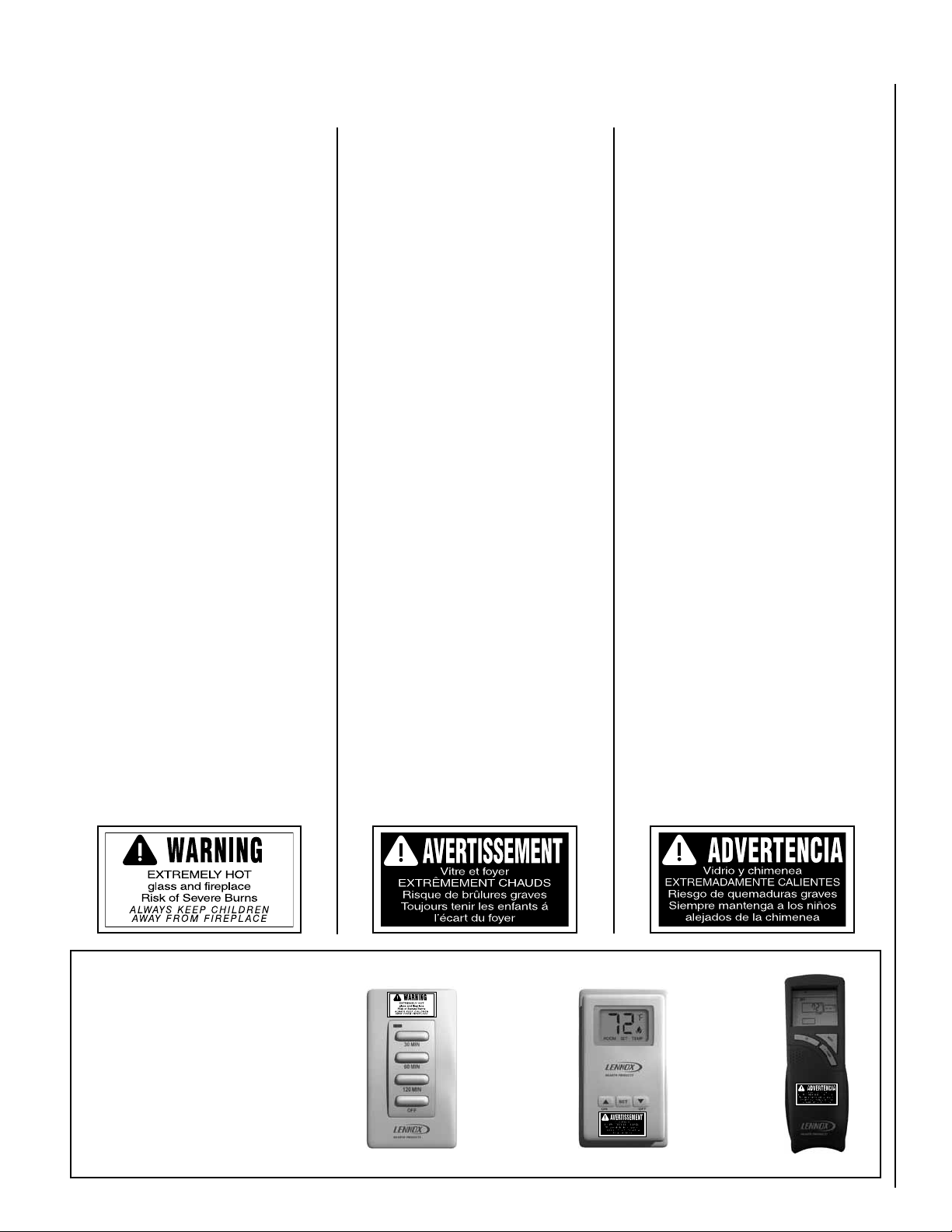
HOMEOWNER’S INSTRUCTIONS - ATTACHING SAFETY IN OPERATION WARNINGS
ATTACHING SAFETY IN OPERATION WARNINGS
Your fireplace has been furnished with safety instruction labels that are to be affixed to the operation and
control point of the fireplace. A safety instruction
label should be affixed to the wall switch plate where
the fireplace is turned on and off (See Figure A) or
wall thermostat (See Figure B) and if used on the
remote control handheld transmitter (Figure C).
The warnings should already have been put in place
when the fireplace initial set-up was completed.
If they are not affixed at these spots, locate the
multi-lingual adhesive labels provided with these
instructions and proceed as follows:
1. Locate the wall switch or wall thermostat that
controls the fireplace (verify the switch operates
the fireplace by turning it on and off). Clean the
wall switch plate or wall thermostat thoroughly
to remove any dust and oils. Affix the label to
the surface of the plate of the wall switch that
controls the fireplace (Figure A) or the wall
thermostat (Figure B). Choose the language
primarily spoken in the home.
2. If a remote control is used to control the fireplace,
locate the transmitter and clean it thoroughly
to remove any dust and oils. Affix the label to
the surface of handheld transmitter (Figure C).
Choose the language primarily spoken in the
home.
3. If you are unable to locate the labels, please call
Lennox Hearth Products or your nearest Lennox
Hearth Products dealer to receive additional
safety instruction labels free of charge.
Cat. No. H8024 Replacement Label Kit
LENNOX HEARTH PRODUCTS
1-800-655-2008
NOTE: English is red text on clear label. French
and Spanish are white text on black label.
APPOSITION DES MISES EN GARDE RELATIVES À
LA SÉCURITÉ D’UTILISATION
Votre foyer a été livré avec des étiquettes de sécurité qui
doivent être collées à côté des dispositifs de contrôle du
foyer. Une étiquette de sécurité doit être collée sur la
plaque de l’interrupteur contrôlant l’allumage du foyer
(voir Figure A) ou sur le thermostat mural (voir Figure
B) et, le cas échéant, sur le boîtier de la télé commande
(Figure C). Les mises en garde auraient dû être collées
au moment de l’installation initiale du foyer. Si ce n’est
pas le cas, prenez les étiquettes adhésives multilingues
fournies avec ces instructions et procédez comme suit:
1. Repérez l’interrupteur ou le thermostat mural
qui contrôle le foyer (vérifiez que l’interrupteur
contrôle le fonctionnement du foyer en le faisant
basculer de Marche à Arrêt, et vice-versa). Nettoyez
soigneusement la plaque murale de l’interrupteur
ou le thermostat mural pour éliminer la poussière
et les traces de graisse ou d’huile. Collez l’étiquette
sur la surface de la plaque de l’interrupteur mural
qui contrôle le foyer (Figure A) ou du thermostat
mural (Figure B). Choisissez la langue qui est
principalement parlée dans la résidence du
propriétaire.
2. Si une télécommande est utilisée pour contrôler le
foyer, nettoyez la soigneusement pour éliminer la
poussière et les traces de graisse ou d’huile. Collez
l’étiquette sur le boîtier de la télécommande (Figure
C). Choisissez la langue qui est principale ment parlée
dans la résidence du propriétaire.
3. Si vous ne trouvez pas les étiquettes, veuillez appeler
Lennox Hearth Products ou votre distribu teur Lennox
Hearth Products local pour recevoir gratuitement
des étiquettes supplémentaires.
Étiquettes de remplacement, n° cat. H8024
LENNOX HEARTH PRODUCTS
1-800-655-2008
Remarque : Le texte anglais est rouge sur un support
transparent. Le texte français et espagnol est blanc
sur un support noir.
COLOCACIÓN DE ADVERTENCIAS DE SEGURIDAD
EN OPERACIÓN
Su chimenea incluye etiquetas de instrucciones de
seguridad que deben colocarse en el punto de operación
y control de la chimenea. Se debe colocar una etiqueta de
instrucciones de seguridad en la placa del interruptor de
pared desde el cual se enciende y se apaga la chimenea
(ver la Figura A) o en el termostato de pared (ver la Figura
B) y en el transmisor de control remoto (Figura C) si
se usa. Las advertencias ya deben haberse colocado
cuando se completó la instalación inicial de la chimenea.
Si no están colocadas en estos lugares, encuentre las
etiquetas adhesivas multilingües proporcionadas con
estas instrucciones y prosiga de la siguiente manera:
1. Identifique el interruptor o el termostato de pared
que controla la chimenea (verifique que el interruptor
opera la chimenea encendiéndola y apagándola).
Limpie bien la placa del interruptor o el termostato de
pared para quitar el polvo y aceite. Pegue la etiqueta
en la superficie de la placa del interruptor que controla
la chimenea (Figura A) o en el termostato de pared
(Figura B). Seleccione el idioma que más se habla
en la casa.
2. Si se usa un control remoto para controlar la
chimenea, encuentre el transmisor y límpielo bien
para quitar el polvo y aceite. Pegue la etiqueta en la
superficie del transmisor (Figura C). Seleccione el
idioma que más se habla en la casa.
3. Si no puede encontrar las etiquetas, sírvase llamar a
Lennox Hearth Products o al distribuidor de Lennox
Hearth Products más cercano para recibir etiquetas
de instrucciones de seguridad adicionales gratuitas.
Juego de etiquetas de repuesto - Nº de cat. H8024
LENNOX HEARTH PRODUCTS
1-800-655-2008
Nota: La etiqueta en inglés es transparente con texto
rojo. Las etiquetas en francés y español son negras
con texto blanco.
SAFETY LABEL DIAGRAMS
Illustrations are for example only.
Your accessories may be different.
Les illustrations sont par exemple
uniquement. Vos accessoires
peuvent être différents.
Las ilustraciones son sólo ejemplos.
Tu accesorios pueden ser diferentes.
Figure A
DIAGRAMMES DES ÉTIQUETTES
DE SÉCURITÉ
Figure B
NOTE: DIAGRAMS & ILLUSTRATIONS ARE NOT TO SCALE.
DIAGRAMAS DE ETIQUETAS DE
SEGURIDAD
Figure C
5
Page 6

APPLIANCE INSTALLATION, SERVICE,
AND MAINTENANCE NOTICES
WARNING: Improper installation,
adjustment, alteration, service or
maintenance can cause injury or
property damage. Refer to the owner’s
information manual provided with this
appliance. For assistance or additional
information consult a qualified installer,
service agency or the gas supplier.
AVERTISSEMENT : Une installation, un
réglage, une modification, une réparation
ou un entretien mal effectué peut causer
des dommages matériels ou des
blessures. Voir la notice de l’utilisateur
qui accompgne l’appareil. Pour de l’aide
ou des renseignements supplémentaires,
consultez un installateur, un technicien
agréé ou le fournisseur de gaz.
Only trim kit(s) supplied by the manufacturer shall be used in the installation of
this appliance.
Seules les trousses de garniture fournies
par le fabricant doivent être utilisées
pour l’installation de cet appareil.
These appliances must not be connected
to a chimney or flue serving a separate
solid fuel burning appliance.
Any change to this appliance and/or
its operating controls is dangerous.
Improper installation or use of this
appliance can cause serious injury or
death from fire, burns, explosion or
carbon monoxide poisoning.
CARBON MONOXIDE POISONING: Early
signs of carbon monoxide poisoning are
similar to the flu with headaches, dizziness and/or nausea. If you have these
signs, obtain fresh air immediately.
Turn off the gas supply to the appliance
and have it serviced by a qualified
professional, as it may not be operating
correctly. Some people are more
affected by carbon monoxide than others,
including pregnant women, people with
heart or lung disease or anemia, those
under the influence of alcohol, and those
at high altitudes.
6
Turn off gas and electrical power to the
fireplace and allow it to cool before
cleaning or servicing the appliance.
The vent termination is hot while in
operation and for a period of time following the use of the fireplace. Young
children should be carefully supervised
when they are in the same area as a hot
termination.
APPLIANCE OPERATION NOTICES
Do not operate appliance with the glass
front removed, cracked, or broken.
These fireplaces are vented gas appliances. Do not burn wood or other
material in these appliances.
This appliance is only for use with the
type of gas indicated on rating plate. This
appliance is not convertible for use with
other gases, unless a certified kit is used.
Cet appareil doit être utilisé uniquement
avec les types de gaz indiqués sur la
plaque signalétique. Ne pas l’utiliser
avec d’autres gaz sauf si un kit de
conversion certifié est installé.
These appliances are designed to operate
on natural gas or propane gas only. The
use of other fuels or combinations of
fuels will degrade the performance of this
system and may be dangerous.
Provide adequate clearances around
air openings and adequate accessibility
clearance for service and proper operation. Never obstruct the front openings
of the appliance.
Do not use this appliance if any part has
been under water. Immediately call a
qualified service technician to inspect
the appliance and to replace any part of
the control system and any gas control
that has been under water.
These fireplaces are designed as supplemental heaters. Therefore, it is advisable
to have an alternate primary heat source
when installed in a dwelling.
CAUTION: Hot while in operation. Do not
touch. Severe Burns may result. Keep
children, clothing furniture, gasoline
and other liquids having flammable
vapors away.
ATTENTION : L’appareil est chaud
lorsqu’il fonctionne. Ne pas toucher
l’appareil. Risque de brûlures graves.
Surveiller les enfants. Garder les
vêtements, les meubles, l’essence ou
autres liquides produisant des vapeur
inflammables loin de l’appareil.
NOTE: DIAGRAMS & ILLUSTRATIONS ARE NOT TO SCALE.
WARRANTY INFORMATION
Your gas appliance is covered by a
limited twenty-year warranty. You will
find a copy of the warranty accompanying
this manual. Please read the warranty to
be familiar with its coverage.
Retain this manual. File it with your other
documents for future reference.
Failure to comply with the installation
and operating instructions provided
will result in an improperly installed
and operating appliance, voiding its
warranty.
Do not attempt to alter or modify the
construction of the appliance or its components. Any modification or alteration
may void the warranty, certification, and
listings of this unit.
GENERAL INFORMATION
The fireplace models covered in this manual
are direct-vent sealed combustion gas fireplace
heaters designed for residential application.
These direct-vent appliances operate with the
combustion chamber completely isolated from
the indoor environment.
All air for combustion is brought in from the
outside and exhaust gases are vented through
the same direct-vent, co-axial (intake/exhaust)
vent system.
The Millivolt appliances have a millivolt gas
control valve with piezo ignition system. If any
optional accessories which require electrical
power are being installed, the electrical power
must be provided at the time of appliance
installation.
The Electronic appliances are designed to
operate on either natural or propane gas. An
electronic intermittent pilot system provides
safe, efficient operation. External electrical
power is required to operate these units.
Page 7
These appliances comply with National
Safety Standards and are tested and listed
by OMNI-Test Laboratories, Inc. (Report No.
116-F-05d-5) to ANSI Z21.88-2009 (in Canada,
CSA-2.33-2009), and CAN/CGA-2.17-M91
(R2009) in both USA and Canada, as vented
gas fireplace heaters.
The Installation must conform to local codes
or, in the absence of local codes, with the
National Fuel Gas Code, ANSI Z223.1/NFPA
54-latest edition, or the Natural Gas and Propane
Installation Code, CAN/CGA B149.1-latest edition. The appliance, when installed, must be
electrically grounded in accordance with local
codes or, in the absence of local codes, the
latest edition of the National Electrical Code,
ANSI/NFPA 70, or the Canadian Electrical Code,
CSA C22.1 - latest editions.
BTU Input
Millivolt Models - The millivolt appliances are
manually controlled and feature a spark igniter
(piezo) that allows the appliance's pilot gas to
be lit without the use of matches or batteries.
This system provides continued service in the
event of a power outage.
Electronic and Millivolt models come standard
with a manually-modulated gas valve; flame appearance and heat output can be controlled at the
gas valve. The BTU Input for these appliances
is shown in Table 1.
Input (BTU/HR) Gas Valves (all models)
Input Rate (BTU / HR)
Models
EDV35
EDV40
EDV45
Nat. Gas Prop. Gas
25,000 high
19,000 low
27,000 high
21,000 low
31,000 high
25,000 low
24,000 high
18,000 low
27,000 high
21,000 low
29,000 high
23,000 low
Table 1
Gas Pressure - All Models
Tables 2 and 3 show the appliances' inlet and
manifold gas pressure requirements:
Inlet Gas Supply Pressure
(all models)
Fuel # Minimum Maximum
Natural Gas
Propane
4.5" WC
(1.12 kPa)
11.0" WC
(2.74 kPa)
10.5" WC
(2.61 kPa)
13.0" WC
(3.23 kPa)
Table 2
Manifold Gas Supply Pressure
(all models)
Fuel #
Natural Gas
Propane
Low
(Lo) 2.2" WC
(0.55 kPa)
(Lo) 6.3" WC
(1.57 kPa)
High
(Hi) 3.5" WC
(0.87 kPa)
(Hi) 10.0" WC
(2.49 kPa)
Table 3
Test gauge connections are provided on the
front of the millivolt and electronic gas control
valve (identified IN for the inlet and OUT for the
manifold side). The control valves have a 3/8"
(10mm) NPT thread inlet and outlet side of the
valve (refer to Figures 2 and 3).
Propane tanks are at pressures that will cause
damage to valve components. Verify that the
tanks have step down regulators to reduce the
pressure to safe levels.
The appliance and its appliance main gas
valve must be disconnected from the gas
supply piping system during any pressure
testing of that system at test pressures in
excess of 1/2 psi (3.5 kPa).
The appliance must be isolated from the
gas supply piping system by closing its
equipment shutoff valve during any pressure
testing of the gas supply piping system at
test pressures equal to or less than 1/2 psi
(3.5 kPa).
Orifice Sizes - Sea Level to High Altitude
(All Models)
These appliances are tested and approved for
installation at elevations of 0-4500 feet (0-1372
meters) above sea level using the standard burner
orifice sizes (marked with an "*" in Table 4).
For elevations above 4500 feet, contact your
gas supplier or qualified service technician.
Flame breadth, height and width will dimenish
4% for every 1,000 feet of altitude.
NOTE: DIAGRAMS & ILLUSTRATIONS ARE NOT TO SCALE.
Deration - At higher elevations, the amount
of BTU fuel value delivered must be reduced
by either:
• Using gas that has been derated by the gas
company.
• Changing the burner orice to a smaller size
as regulated by the local authorities having
jurisdiction and by the (USA) National Fuel
Gas Code NFPA 54/ANSI Z223.1 - latest
edition or, in Canada, the CAN/CGA-B149.1
codes - latest edition.
Burner Orifice Sizes
Elevation 0-4500 feet ( 0-1372 meters)
Model
EDV35
EDV40
EDV45
Table 4
Nat.Gas
drill size (inches)
#42 (0.0935")*
H3721•
#40 (0.0980")*
69L96•
#37 (0.1040")*
24M10•
* Standard size installed at factory
• Part /Cat. Number
Propane
drill size (inches)
(0.0570")*
H8998•
#53 (0.0595")*
39L10•
(0.0620")*
21L01•
In Canada - CAN/CGA-2.17-M91 (R2009)
(high altitude):
THE CONVERSION SHALL BE CARRIED
OUT BY A MANUFACTURER’S AUTHORIZED REPRESENTATIVE, IN ACCORDANCE WITH THE REQUIREMENTS OF
THE MANUFACTURER, PROVINCIAL OR
TERRITORIAL AUTHORITIES HAVING
JURISDICTION AND IN ACCORDANCE
WITH THE REQUIREMENTS OF THE
CAN/CGA-B149.1 OR CAN/CGA-B149.2
INSTALLATION CODES.
Burn-in Period
During the first few fires of this appliance there
will be some odor due to the curing of the
paint and burning off of lubricants used in the
manufacturing process. Depending on your
use, the burn-in period may take a few hours
or a few days.
KEEP YOUR HOUSE WELL VENTILATED
DURING THE CURING PROCESS. THE ODOR
AND HAZE EMITTED DURING THE CURING
PROCESS CAN BE QUITE NOTICEABLE AND
MAY SET OFF A SMOKE DETECTOR.
If an optional blower is installed, Do Not turn
it on during the Burn-In period.
A white film may develop on the glass front
during the first few fires as part of the curing
process. The glass should be kept clean during
the first two weeks of use to prevent the film from
baking on (making it very difficult to remove).
See Cleaning Glass on Page 10.
7
Page 8
OPERATION AND CARE OF YOUR APPLIANCE
Pilot Assembly
Pilot Assembly
Burner Assembly
Burner Assembly
CPI Switch*
Door Latch
Main Gas
Shut-Off Valve
Gas Valve
Battery
Holder
DFC Board
*CPI Switch Positions
(o) = Intermittent Pilot Mode
(-) = Standing Pilot Mode
Pilot Assembly
Burner Assembly
Gas Controls/Control Compartment
Access
WARNING
Young children should be carefully supervised when they are in the
same room as the appliance. Toddlers, young children and others
may be susceptible to accidental contact burns. A physical barrier is
recommended if there are at risk individuals in the house. To restrict
access to a fireplace or stove, install an adjustable safety gate to keep
toddlers, young children and other at risk individuals out of the room
and away from hot surfaces.
AVERTISSEMENT
Les jeunes enfants devraient être surveillés étroitement lorsqu’ils se trouvent dans la même pièce que l’appareil. Les tout petits, les jeunes enfants
ou les adultes peuvent subir des brûlures s’ils viennent en contact avec
la surface chaude. Il est recommandé d’installer une barrière physique
si des personnes à risques habitent la maison. Pour empêcher l’accès
à un foyer ou à un poêle, installez une barrière de sécurité; cette mesure
empêchera les tout petits, les jeunes enfants et toute autre personne à
risque d’avoir accès à la pièce et aux surfaces chaudes.
ELECTRONIC MODELS
The gas controls can be found behind the hinged
drop-down panel.
To open the hinged drop-down panel, actuate
the spring loaded magnetic catches securing
the door. First, gently depress the upper right
top corner of the panel until the magnet catch
"pops" the door free. Then, gently pulling the
panel forward, disengage the left magnet catch
and allow the panel to swing down to open.
On millivolt systems, the piezo igniter, Hi/Lo
flame adjustment knob, and pilot and main gas
ON/OFF control knob are located in the control
compartment. On both millivolt and electronic
systems the gas valve is located in the control
compartment. See Figure 1.
Remove the bottom compartment door by
sliding the hinge pin, located at the door’s left
side, to the right until it disengages from the
left corner post hole. Pull the door diagonally
to the left, away from the fireplace.
To ease door closure, depress the catches to
place them in their retracted position until they
stay there, then close the door.
Main Gas
Shut-Off Valve
*CPI Switch - Switches from an
intermittent pilot mode to a standing pilot mode (a standing pilot
stays lit when the fireplace is off).
Main Gas
Shut-Off Valve
Figure 1 - Control Compartment Access
DFC Board
Battery
Holder
*CPI Switch Positions
(o) = Intermittent Pilot Mode
(-) = Standing Pilot Mode
MILLIVOLT MODELS
Gas Valve
(Optional) Burner
Burner ON/OFF
ON/OFF Switch
Switch (optional)
Gas Valve
CPI Switch*
Piezo
Glass Door
Door Latch
Spring Latch
Door Latch
Glass Door
Spring Latch
Operation of millivolt and electronic gas control systems are different. Before lighting and
operating your appliance determine if you have
a millivolt or electronic appliance.
Refer to Figure 1 for access to the gas control
valve. Millivolt appliances will be fitted with the
gas control valve shown in Figure 2.
Appliances with electronic systems will be fitted
with the electronic valve shown in Figure 3.
Familiarize yourself with the gas control valve
that your appliance uses.
8
NOTE: DIAGRAMS & ILLUSTRATIONS ARE NOT TO SCALE.
Page 9
Variable Flame Height Adjustment
Variable Flame Height Adjustment
Inlet Pressure Port
Manifold Pressure Port
IN
TPTH TP TH
I
H
L
O
W
P
I
L
O
T
OUT
F
F
O
P
I
L
it
O
T
O
N
Main Gas
SIT Millivolt Gas Valve
Control Knob
NOTE: The piezo igniter is located in the control compartment - refer to Figure 1
Figure 2
If your millivolt appliance is equipped with an
optional remote wall switch or remote control
kit and the pilot is lit, the appliance main burner
may be turned on and off with the wall switch
or remote control.
Electronic Appliances
To light electronic appliances refer to the
detailed lighting instructions found in both
English and French on Pages 25 and 26 of
these instructions respectively. Electronic
Manifold
(OUT)
Test Port
Orange
Wire
(From DFC
Wire
Harness)
Inlet (IN)
Test Port
Hi/Lo Flame
Control Knob
Green Wire
(From DFC Wire
Harness)
appliance lighting instructions may also be
found on the pull out lighting instruction labels
attached to the gas control valve.
All Electronic and Millivolt appliances are
equipped with a variable gas control valve. Flame
height for these models may be adjusted through
a range between fixed low and high settings,
alternately, while the appliance is in operation.
Adjust the flame height as desired after lighting
the appliance by rotating the variable adjustment
control knob located on the front of the valve
(refer to Figures 2 and 3).
Main Gas Inlet
3/8" NPT
Figure 3 - SIT Electronic Gas Valve
Millivolt Appliances
To light millivolt appliances refer to the detailed
lighting instructions found on Page 23 (English)
and Page 24 (French). Millivolt appliance
lighting instructions may also be found on the
pull out lighting instruction labels attached to
the gas control valve.
Millivolt appliances are fitted with an ON/OFF
Rocker Switch for appliance ON/OFF control.
Refer to Figure 1 for its location. Once the
pilot is lighted, the ON/OFF rocker switch will
control the appliance ON/OFF operation. To
operate: Toggle the switch between its ON and
OFF positions.
Yellow Ground Wire
(From DFC Wire
Harness)
If your electronic appliance is equipped with an
optional wall switch or remote control kit, the
appliance main burner may be turned ON and
OFF using the wall switch or remote control.
CPI switch located to the left of the gas valve
switches the pilot from intermittent operation
(pilot goes out when the fireplace is turned off)
to continuous pilot mode. The rocker switch
will not turn the burner on or off.
NOTE: DIAGRAMS & ILLUSTRATIONS ARE NOT TO SCALE.
9
Page 10
MAINTENANCE
(See Maintenance Schedule, Page 22)
Refer to the maintenance schedule for maintenance
tasks, procedures, frequency and by whom they
should be performed. Always verify proper operation of the appliance after servicing.
WARNING
Turn off gas and electrical power
to the fireplace and allow it to
cool before cleaning or servicing
the appliance.
CAUTION: Wear gloves and safety
glasses for protection while doing
required maintenance.
Verify proper operation after servicing.
S'assurer que l'appareil fonctionne adéquatement une fois l'entretien terminé.
Always turn off gas to the pilot (millivolt
appliances) before cleaning. Before relighting, refer to the lighting instructions
in this manual. Instructions are also found
on a pull-out panel located in the control
compartment.
Always keep the appliance area clear
and free from combustible materials,
gasoline and other flammable liquids.
WARNING: Do not use abrasive cleaners
on glass. Never clean the glass when it
is hot.
The viewing glass should be cleaned periodically to remove any build-up caused from the
following:
• During start-up, it is normal for condensation to form on the inside of the glass (this
condensation and fog will usually disappear
in a few minutes). The moisture can cause
lint, dust and other airborne particles to cling
to the glass surface.
• Initial curing of the high temperature paint
and burning off of lubricants used in the
manufacturing process may result in a film
on the glass.
• A white coating may form on the glass as a
result of impurities and minerals in the fuel.
It is recommended that the glass be cleaned
two or three times during each heating season,
depending on the circumstances present. The
following cleaning solutions are approved for
use to clean glass:
• Non-ammonia based household cleaner
• 50%-50% mix of white vinegar and water
• Gas replace/stove glass cleaner
Inspect Glass Gasket - Visually inspect the
gasket on the backside of the glass enclosure
panels. The gasket surface must be clean, free
of irregularities and seated firmly.
Clean Control Compartment
Replacing Logs
If the logs become damaged by accident or
improper handling and need replacement, use
only the proper replacement logs from manufacturer (see Page 29 for ordering information).
Re-Install Embers and Logs
Carefully follow placement instructions on
Pages 12 through 14. All logs should fit
onto corresponding pins and/or log stoppers. This will ensure a proper flame and safe
combustion.
Inspect Wiring
Refer to wiring diagrams on Page 17.
CAUTION: Label all wires prior to disconnection when servicing controls. Wiring
errors can cause improper and dangerous
operation. Verify proper operation after
servicing.
ATTENTION: Au moment de l'entretien
des commandes, étiquetez tous les fils
avant de les débrancher. Des erreurs
de cáblage peuvent entraîner un fonctionnement inadéquat et dangereux.
Inspect and clean all wire connections. Ensure
that there is no melting or damage. Inspection
should include:
• Terminals at the Valve
• OFF/ON Switch
• (Optional Control Switch) Wall Thermostat,
Remote Control or Remote Wall Switch Kit
Inspect Venting System
The appliance and venting system should be
thoroughly inspected before initial use and
at least annually by a qualified service technician (inspection should include ensuring that
exhaust or intake passages are unobstructed
and vent components are properly assembled
and not damaged). Homeowner must contact
a qualified service technician at once if any
abnormal condition is observed.
If the venting system is disassembled for any
reason, a qualified service technician should
follow vent installation instructions for proper
reassembly and proper sealing of the venting
system components. However, more frequent
periodic inspections and cleanings should be
performed by the homeowner.
Cleaning Glass
(see Front Glass Enclosure Panel, Removal and
Installation on Page 11).
NOTE: Clean glass after first two weeks of
operation (after Burn-In period is over) and then
only when necessary and when the fireplace is
cool. Wipe surface with a clean, dampened, soft
cloth. Follow with a dry, soft towel as desired.
Take care not to scratch the glass surface.
10
Keep control compartment clean by vacuuming
or brushing at least twice a year. More frequent
cleaning may be required due to excessive lint
from carpeting, bedding materials, etc. It is
important that control compartments, burners
and circulating air passageways of the appliance
be kept clean.
Clean Logs And Burner
Carefully remove the logs (use care when handling the fiber logs, as they become quite fragile
after curing). Vacuum out any foreign matter
(lint, carbon, etc.) on the burner. Ensure the
burner ports are “open.” Remove any carbon
deposits from the under side of the logs using
a vacuum cleaner, or a soft bristled brush (i.e.
paint brush).
NOTE: Improper positioning of logs can create
carbon build-up and will alter the performance
of the appliance.
Inspect Burner Flame and Pilot Flame
Appearance
Periodically do a visual check of the burner
flame and the pilot flame. Ensure that the burner
flame appearance resembles the flame shown
in Figures 9, 10 and 11 and as described in
Flame Appearance and Sooting on Page 15.
Refer to Figures 13 and 14 on Page 16 for
more information about the pilot flame appearance. Contact a qualified service technician at
once if any abnormal condition is observed.
Small Area Paint Touch-up
Only use a factory supplied paint kit for touchups. Paint is available at your local Lennox
Hearth Products dealer. Never attempt to
paint a hot fireplace.
Do not attempt to repaint the appliance until
the finish is completely cured (see Burn-In
Period on Page 7). If the sur face later becomes
stained or marred, it may be lightly sanded and
touched up with spray paint.
Page 11

Front Glass Enclosure Panel, Removal
Glass Door
Spring Latch
Lower Compartment Door and Hinge
Glass Door
Firebox Floor
Bottom Vee-flange
Glass Door Frame
Top Flange
Glass Door Frame
Modesty
Panel
and Installation
Only doors certified with the appliance
shall be used.
Installing Glass Enclosure Panel
(see Figure 4)
WARNING
• Do not attempt to substitute the
materials used on these doors,
or replace cracked or broken
glass.
•Handlethisglasswithextreme
care! Glass is susceptible to
damage - Do not scratch or
handle roughly while reinstalling the glass door frame.
•Theglassdoor(s)ofthisappliance must only be replaced as
a complete unit as provided
by the manufacturer. Do not
attempt to replace broken,
cracked or chipped glass separately.
• Do not attempt to touch the
front enclosure glass with your
hands while the fireplace is in
use.
WARNING
Do not operate appliance with
the glass front removed, cracked
or broken.
Seules des portes certifiées pour cet
appareil doivent être utilisées.
WARNING: DO NOT abuse glass door by
striking or slamming shut.
Removing Glass Enclosure Panel
(see Figure 4)
Remove the top radiant panel or louver assembly
(optional kit).
To access the glass door securing spring latches,
first open the lower control compartment door
(Figure 4) by pushing in simultaneously the left
and right top corners of the door (the door is
hinged at the bottom).
Remove the bottom compartment door by
sliding the hinge pin, located at the door’s left
side, to the right until it disengages from the
left corner post hole. Pull the door diagonally
to the left, away from the fireplace.
Locate the two (2) glass door spring latches at
the top of the control compartment (see Figure
4). Pull out each spring latch until it disengages
from the door frame bottom vee-flange. Remove
the door by tilting it outward at the bottom and
lifting it up. Set the door aside, taking care to
protect it from inadvertent damage.
Retrieve the glass door. Visually inspect the
gasket on the backside of the frame. Gasket
surface must be clean, free of irregularities
and seated firmly.
Position the door in front of the firebox opening
with the bottom of the door held away from the
fireplace (Figure 4). Hook the top flange of the
door frame over the top of the firebox frame.
Let the bottom of the door frame swing gently
in towards the fireplace ensuring that the gasket
seats evenly as the door frame draws shut. Fasten the two spring latches located underneath
the firebox floor to the door's vee-flange.
AVERTISSEMENT
Ne pas utiliser l'appareil si le
panneau frontal en verre n'est
pas en place, est craqué ou
brisé.
Any safety screen or guard
removed for servicing the appli-
WARNING
ance must be replaced prior to
operating the appliance.
AVERTISSEMENT
Tout écran ou protecteur retiré
pour permettre l’entretien de
l’appareil doit être remis en
place avant de mettre l’appareil
en marche.
(shown with optional louver panel)
Figure 4
11
NOTE: DIAGRAMS & ILLUSTRATIONS ARE NOT TO SCALE.
Page 12

Glowing Embers
INSTALL VOLCANIC STONE, GLOWING
EMBERS AND LOGS
NOTE: Turn off all electricity to the appliance
before you install volcanic stone, embers and
logs.
WARNING
• DO NOT attempt to install the logs
until the appliance installation
has been completed, the gas
line connected and tested for
leaks and the initial burner
operation has been checked out.
•
The size and position of the log
set was engineered to give the
appliance a safe, reliable and
attractive flame pattern. Any
attempt to use a different log
set in the fireplace will void
the warranty and will result
in incomplete combustion,
sooting, and poor flame quality.
•
Logs get very hot and will remain
hot up to one hour after gas
supply is turned off. Handle
only when logs are cool. Turn
off all electricity to the appliance
before you install grate, volcanic
stone, vermiculite, embers and
logs.
•
This appliance is not designed
to burn wood. Any attempt to
do so could cause irreparable
damage to the appliance and
prove hazardous to your safety.
•
If logs are not installed
according to the log installation
instructions, flame impingement
and improper combustion could
occur and result in soot and/or
excessive production of carbon
monoxide (CO), a colorless,
odorless, toxic gas.
REFERENCE
Firebox Accessories / Parts
Cat. No. Model No. Description
88L53 FGE Bag of Glowing Embers
80L42 FDVS
Bag of Decorative
Volcanic Stone
Figure 6
Step 1. Remove the appliance front door (see
Removing Glass Encloslure panel on Page 11.
Step 2. Install decorative volcanic stone -
Sprinkle the decorative volcanic stone in a pleasing pattern. The volcanic stone should be placed
directly on top of the firebox bottom, along the
front and to the back at the right and left sides of
the burner. Position any optional ceramic fiber
liners before placing the stone. Logs should be
positioned after the volcanic stone.
NOTE: This appliance is provided with enough
Glowing Embers for several applications, do
not feel compelled to use all that is in a new
bag. For best glowing effect, replace the ember
material annually. Replacement Glowing Embers are available (Catalog Number 88L53).
Step 3. Separate the Glowing Ember
(Rockwool) into pieces about the size of a
quarter (Figure 5). Keep the pieces fluffed up,
not matted. Distribute these pieces over the
front surface of the burner, as shown in Figure
6. Do not use more than is necessary. When
properly positioned, the Glowing Embers will
cover approximately 65% of the front burner
and with no appreciable gaps or openings.
Ensure that the main burner ports remain
uncovered by the ember material.
Glowing Embers
Separate into Quarter
Size (separate) Pieces
Bag of Glowing
Embers (rockwool)
Figure 5
Step 4. Placement of Logs -
All top logs that rest on lower logs, do so over
notches, indents or nubs. Proper log placement
is critical to prevent sooting. Logs should be
placed in the gaps between the flame peaks and
should be positioned so they do not impinge
the flames.
Step 5. Position the individual logs as shown
in Figures 7 and 8. Logs should be placed in
the order shown. All logs that have notches
to fit over the grate tines should be positioned
with these notches directly against the grate.
Handle logs carefully to prevent breakage.
Proper log placement is critical to encourage
outstanding flame appearance and prevent
sooting. When positioned properly as shown,
logs will be positioned between flame peaks
and will not impinge any flames.
Refer to Figure 7 for EDV35 Series appliances
and to Figure 8 for EDV40 and EDV45 Series
appliances.
12
NOTE: DIAGRAMS & ILLUSTRATIONS ARE NOT TO SCALE.
Page 13

EDV35 LOG PLACEMENT
Log
2
1
3
4
6
5
Number Description
1 Log, Rear
2 Log, Diagonal/Left
3 Log, Diagonal/Right
4 Log, Front/Left
5 Log, Top/Right
6 Log, Front/Center
Catalog Number for the entire log set: 55M02
Locating Pins
2
1
Align Groove At The Bottom
Of Log (1) Over The Grate And
Push It Towards The Rear.
Locating Pin
Align The Hole On The Log (5) Over The Locating Pin
And Postition The Notch Over The Grate As Shown
4
Align The Groove In The Bottom Of Log (4) Over
The Grate And Slide It Toward The Front.
5
Align The Holes In One End Of Logs 2 & 3 Over The
Locating Pins And Align The Grooves On The Other
End Over The Grate And Push It Toward The Rear
Figure 7
NOTE: DIAGRAMS & ILLUSTRATIONS ARE NOT TO SCALE.
3
6
Position The Grooves On Log (6)
Against The Grate As Shown
13
Page 14

EDV40 AND EDV45 LOG PLACEMENT
Log
Number Description
1 Log, Rear
2 Log, Diagonal/Left
3 Log, Diagonal/Right
4 Log, Front/Left
5 Log, Top/Right
6 Log, Front/Center
Catalog Number for the entire log set: 55M03
1
2
1
3
4
6
5
Align The Hole On The Log (5) Over The Locating Pin
And Postition The Notch Over The Grate As Shown
4
5
Locating Pins
Align Groove At The Bottom
Of Log (1) Over The Grate And
Push It Towards The Rear.
Locating Pin
2
Align The Holes In One End Of Logs 2 & 3 Over The
Locating Pins And Align The Grooves On The Other
End Over The Grate And Push It Toward The Rear
Align The Groove In The Bottom Of Log (4)
Over The Grate And Slide It Toward The Front.
3
6
Position The Grooves On Log (6)
Against The Grate As Shown
14
Figure 8
NOTE: DIAGRAMS & ILLUSTRATIONS ARE NOT TO SCALE.
Page 15

BURNER ADJUSTMENTS
(QUALIFIED TECHNICIANS ONLY)
Flame Appearance and Sooting
Proper flame appearance is a flame which is
blue at the base and becomes yellowish-orange
in the body of the flame.
When the appliance is first lit, the entire flame
may be blue and will gradually turn yellowishorange during the first 15 minutes of operation.
If the flame remains blue, or if the flame is
orange with evidence of sooting (black tip), the
air shutter opening may need to be adjusted.
If the air shutter opening is closed too far,
sooting may develop. Sooting is indicated by
black puffs developing at the tips of very long
orange flames. Sooting results in black deposits
forming on the logs, appliance inside surfaces
and on exterior surfaces adjacent to the vent
termination.
Sooting is caused by incomplete combustion
in the flames and lack of combustion air entering the air shutter opening. To achieve a warm
yellowish-orange flame with an orange body
that does not soot, the shutter opening must be
adjusted between these two extremes.
Figure 9
EDV35
Air Shutter Adjustment Guidelines
• If there is smoke or soot present, rst check
the log set positioning to ensure that the
flames are not impinging on any of the logs.
If the log set is properly positioned and a
sooting condition still exists, then the air
shutter opening should be increased.
• The more offsets in the vent system, the larger
the air shutter opening will need to be.
• An appliance operated with the air shutter
opened too far, may have flames that appear
blue and transparent. These weak, blue and
transparent flames are termed anemic.
• Propane models may exhibit ames which
candle or appear stringy. If this is present
and persists, adjust the air shutter to a more
closed position, then operate the appliance
for a few more minutes to ensure that the
flame normalizes and the flames do not
appear sooty.
The following chart is provided to aid you in
achieving the correct air shutter adjustment
for your installation.
Air Shutter Adjustment Guidelines:
Amount of
Primary Air
If air shutter is
closed too far
If air shutter is
open too far
Flame
Color
Flame will
be orange
Flame will
be blue
Air Shutter
Adjustment
Air shutter
gap should be
increased
Air shutter
gap should be
decreased
Figure 10
Figure 11
NOTE: DIAGRAMS & ILLUSTRATIONS ARE NOT TO SCALE.
EDV40
EDV45
15
Page 16

MILLIVOLT
Thermocouple
Hood Igniter Rod
3/8" Min
(9 mm)
Thermopile
Pilot
Nozzels
Burner Flame Adjustments
Igniter
WARNING
Burner
Venturi
Tube
• Air shutter adjustment should
only be performed by a qualified professional service technician.
• Ensure front glass panel are
in place and sealed during
adjustment.
CAUTION
• Soot will be produced if the
air shutter is closed too much.
Any damage due to sooting,
resulting from improperly
setting the air shutter, is not
covered under the warranty.
• The air shutter door and
nearby appliance surfaces
are hot. Exercise caution to
avoid injury while adjusting
flame appearance.
1. Refer to Figures 9, 10 and 11 for proper
flame app earance. To adjust the flame, rotate
the adjustment rod toward the back or toward
the front of the fireplace (rod located in the
lower control area). Position the air shutter
to the factory setting as shown in the table
in Figure 12.
2. Light appliance (follow lighting procedure
on lighting label in control compartment or
see the Pages 23 through 26).
3. Allow the burner to operate for at least 15
minutes while observing the flame continuously to ensure that the proper flame appearance has been achieved. If the following
conditions are present, adjust accordingly.
• If ame appears weak or sooty, adjust
the air shutter, incrementally, to a more
open position until the proper flame
appearance is achieved.
• If ame remains blue, adjust the air
shutter, incrementally, to a more closed
position until the proper flame appearance is achieved.
4. Leave the control knob (off/pilot/on) in the
ON position and the burner OFF/ON switch
OFF (and remote switches, if applicable).
5. When satisfied that the burner flame appear-
ance is normal, re-install the lower control
compartment door then proceed to finish
the installation.
Air Shutter
Opening
Orifice
Air
Shutter
Door
Increase
Air Shutter
Opening
Air Shutter
Adjusting
Arm
Factory Shutter Opening Setting
Models
EDV35
EDV40
EDV45
Decrease
Air Shutter
Opening
Main Burner
Natural Gas
inches (mm)
1/8 (3.2) 3/8 (9.5)
Propane Gas
inches (mm)
Figure 12
Millivolt Appliance Checkout
The pilot flame should be steady, not lifting
or floating. Flame should be blue in color with
traces of orange at the outer edge.
The top 3/8" (10 mm) at the pilot generator
(thermopile) and the top 1/8" minimum (tip)
of the quick drop out thermocouple should be
engulfed in the pilot flame.
The flame should project 1" (25 mm) beyond
the hood at all three ports (see Figure 13).
Replace logs if removed for pilot inspection.
To light the burner; turn “ON” the remote wall
switch and rotate the gas valve control knob
counterclockwise to the “ON” position (“ON”
will be at the top side of the valve).
Figure 13 - Millivolt Pilot
Electronic Appliance Checkout
To light the burner, turn ‘ON’ the wall or remote
control switch. Ensure the igniter lights the pilot.
The pilot flame should engulf the flame rod as
shown in Figure 14.
Flame Rod
Flame Rod
(Sensor)
(sensor)
Igniter
Pilot
Hood
Pilot Hood
Figure 14 - Electronic Pilot
16
NOTE: DIAGRAMS & ILLUSTRATIONS ARE NOT TO SCALE.
Page 17

JUNCTION BOX
Millivolt Wiring Diagram
WIRING DIAGRAMS
Wiring diagrams are provided here for reference
purposes only. This information is also provided
on schematics attached directly to the appliance
on a pullout panel located within the control
compartment.
CAUTION: LABEL ALL WIRES PRIOR TO
DISCONNECTION WHEN SERVICING
CONTROLS. WIRING ERRORS CAN
CAUSE IMPROPER AND DANGEROUS
APPLIANCE OPERATION.
ATTENTION: AU MOMENT DE
L'ENTRETIEN DES COMMANDES,
ÉTIQUETEZ TOUS LES FILS AVANT DE
LES DÉBRANCHER. DES ERREURS
DE CÁBLAGE PEU-VENT ENTRAÎNER
UN FONCTIONNEMENT INADÉQUAT
ET DANGEREUX.
If any of the original wire as supplied must be replaced,
it must be replaced with Type AWM 105º C – 18 GA. wire.
TH
TP
TP
TH
Thermopile
Field Wired
Factory Wired
APPLIANCE-MOUNTED ON/OFF SWITCH
*OR OPTIONAL WALL-MOUNTED ON/OFF SWITCH
OR OPTIONAL THERMOSTAT
OR OPTIONAL REMOTE CONTROL RECEIVER
*Turn the appliance-mounted ON/OFF burner control switch
to the OFF position if an optional
control switch is installed.
Figure 15
REPLACEMENT PARTS
A complete parts list is found at the end of
this manual. Use only parts supplied from the
manufacturer.
With proper care and maintenance, your appliance will provide many years of enjoyment. If
you should experience any problem, first refer
to the troubleshooting guide in this manual. If
problem persists, contact your Lennox Hearth
Products dealer or distributor.
Normally, all parts should be ordered through your
Lennox Hearth Products distributor or dealer.
R
BATTERY HOLDER
AC/DC
POWER
ADAPTOR
Y
G
O
B
PROFLAME VALVE
B
R
B
W
G
OPTIONAL
REMOTE RECEIVER
ON/OFF SWITCH
WALL SWITCH
WIRING COLOR CODE
B = BLACK
BR = BROWN
GY = GRAY
PU = PURPLE
R = RED
P/N 580491-01
120V AC
HOT
NEUTRAL
GROUND
LIMIT SWITCH
B-VENT MODELS
ONLY
BL = BLUE
G = GREEN
O = ORANGE
W = WHITE
Y = YELLOW
SCHEMATIC REPRESENTATION ONLY
Figure 16 - Wiring Diagram - Electronic Gas Valves
Parts will be shipped at prevailing prices at
time of order.
When ordering repair parts, always give the
following information:
1. The model number of the appliance.
2. The serial number of the appliance.
3. The part number.
4. The description of the part.
5. The quantity required.
6. The installation date of the appliance.
If you encounter any problems or have any
questions concerning the installation or application of this system, please contact your
dealer or distributor.
LENNOX HEARTH PRODUCTS
1508 Elm Hill Pike, Suite 108
Nashville, TN 37210
visit us at www.LennoxHearthProducts.com
1-800-655-2008
PRODUCT REFERENCE INFORMATION
We recommend that you record the following
important information about your fireplace.
Please call Lennox Hearth Products for the
phone number of your nearest Lennox Hearth
Products dealer who will answer your questions
or address your concerns.
W
BL
PILOT TUBE
SPARK WIRE CABLE
PILOT GROUND WIRE
R
R
ELECTRONIC PILOT ASSEMBLY
IGNITER ROD
FLAME SENSOR
B
Y
G
O
W
PROFLAME DFC BOARD
BL
G
DFC WIRE HARNESS
OPTIONAL CPI SWITCH
OFF (O) = INTERMITTENT PILOT MODE
ON (-) = STANDING PILOT MODE
Y
B
B
HOOD
B
PILOT
SENSOR
CABLE
Your Fireplace's Model Number ___________________________________________
Your Fireplace's Serial Number ___________________________________________
The Date On Which Your Fireplace Was Installed ______________________________
The Type of Gas Your Fireplace Uses _______________________________________
Your Dealer's Name ___________________________________________________
NOTE: DIAGRAMS & ILLUSTRATIONS ARE NOT TO SCALE.
17
Page 18

ACCESSORY COMPONENTS
Product Reference Information
Cat.
No.
H9026 EDV35RNM
H9027 EDV35RPM
H9028 EDV35RNE
H9029 EDV40RNM
H9030 EDV40RPM
H9031 EDV40RNE
H9032 EDV45RNM
H9033 EDV45RPM
H9034 EDV45RNE
State-of-the-art control with touch screen
operation
• Backlit LCD display
• Wall mounted docking station for the trans-
mitter
• Thermostatic or manual ON/OFF
• Programmable Weekday/Weekend modes
• Flame icon and low battery indicator
• Receiver may be wall mounted or placed in
the valve compartment
• Includes batteries
Remote, Touch Screen, Thermostat, On/Off
Cat. No. Model No. Description
H8865 RC-S-TOUCH Remote Control
Model Ship.
Weight
78 lb. 9.09 cu. ft.
78 lb. 9.09 cu. ft.
78 lb. 9.09 cu. ft.
86 lb. 10.61 cu. ft.
86 lb. 10.61 cu. ft.
86 lb. 10.61 cu. ft.
108 lb. 14.01 cu. ft.
108 lb. 14.01 cu. ft.
108 lb. 14.01 cu. ft.
Ship.
Volumn
Thermostatic or Manual modes
• LCD Display
• Up to 9 hour Count down Timer
• Includes batteries
• Child lock
• Low battery indicator
• Receiver may be wall mounted or placed in
the valve compartment
Remote, LCD Stat, Thermostat, On/Off
Cat. No. Model No. Description
H8861 RC-S-STAT Remote Control
Cost Effective Solution
• Simple On/Off operation
• Works with millivolt and low voltage electronic
ignition controls
Kit includes:
Remote and Receiver
G-Fire Remote, Simple On/Off
Cat. No. Model No. Description
H8840 KIT-RC-G-FIRE Remote Control
Wall Thermostat
• Wall surface mounted
• Thermostat or manual ON/OFF operation
• Large LCD screen to display room and set
temperature in ºF and ºC
• Connects to wall switch wire
Wall Thermostat, On/Off and
Thermostatic functions
Cat. No. Model No. Description
H8864 WS-S-TSTAT Wall Thermostat
ON/OFF Wall Switch Kit
The ON/OFF wall switch may be used to control
the operation of the fireplace burner as an
alternative to the optional unit-mountable ON/
OFF rocker switch. Install the wall switch in a
convenient location near the fireplace.
ON/OFF Wall Switch
Cat. No. Model No. Description
18
85L87 FWSK ON/OFF Wall Switch
Flame and Heat modulation
• Includes solenoid for SIT millivolt valves
• Thermostatic, manual or up to 9 hour Count-
down Timer modes
• 3 Fan speed settings
• Child lock
• Low battery indicator
• Wall clip included
• Includes batteries
Remote With Hi/Low Flame, Millivolt
Cat. No. Model No. Description
H8862 RC-S-MODMV Remote Control
NOTE: DIAGRAMS & ILLUSTRATIONS ARE NOT TO SCALE.
Wall Control
• 4-button timer with 30/60/120/OFF minutes
• Wall surface mounted
• Connects to wall switch wire
• Perfect for rental and resort applications
Wall Switch, Countdown Timer
Cat. No. Model No. Description
H8863 WS-S-TMR Wall Switch
Page 19

ACCESSORY COMPONENTS CONTINUED
(FBK-200 Models Only)
Manual or up to 3 hr Countdown Timer modes
• LCD display
• Displays room temp. in ºF or ºC
• Flame icon and low battery indicator
• Includes batteries
• Wall clip included
• Receiver may be wall mounted or placed in
the control compartment
• Includes white face plate
• Flame icon
• Low battery indicator
• Batteries included
Remote, Two Button, Timer,
On/Off Or Timer Mode
Cat. No. Model No. Description
H8860 RC-S-1 Remote Control
Black Louvers
Catalog No.
Model No.
EDV35
EDV40
EDV45
Top Louver Kit Bottom Louver Kit
Model No.
H6337 H6344
H2727 H6345
H3146 H6346
These louvers are designed to replace the
standard radiant panels that are provided with
the appliance.
Termination Shroud
(Fits H1968)
Deluxe Termination
Guard (Fits 94L10)
Square Termination
Guard (Fits 94L10)
Termination Guard Kits
The vent termination guards may be used to cover the
vent termination on the exterior of the home to minimize exposure to the hot surface of the termination.
Termination Guard Kits
(all models)
Cat. No. Model No. Description
H5820 4.5HTSK Termination Shroud
87L02 SV4.5HGS
17M52 SV4.5HGS-1
Termination Guard,
Deluxe
Termination Guard,
Square
Unit-Mountable ON/OFF Rocker Switch Kit
(Millivolt systems only)
The rocker switch may be used to provide ON/
OFF operation as an alternative to the optional
wall switch. The rocker switch installs directly
in the gas valve mounting bracket (millivolt gas
valve-equipped fireplaces only).
Rocker Switch Kit
Cat. No. Model No. Description
80L41 FRS Rocker Switch Kit
Blower Kits
Cat. No. Model No. Description
80L84 FBK-100 Single Speed
80L85 FBK-200
80L86 FBK-250
Variable Speed with
wall-mountable switch
Heat activated variable speed with unit
mounted switch
Forced Air Kit
The FBK-100 blower provides constant velocity
forced air circulation. The FBK-200 assembly
with variable speed, wall-mountable switch
provides variable speed forced air circulation.
The FBK-250 assembly with heat activation and
a unit mounted switch which provides variable
speed forced air circulation.
NOTE: DIAGRAMS & ILLUSTRATIONS ARE NOT TO SCALE.
Touch-Up Paint Kit
Repair of minor scratches and discoloration
of the appliance painted surfaces may be accomplished with the touch-up paint kit.
Touch-Up Paint (Black) Kit
Cat. No. Model No. Description
90L73 TPK-B Touch-Up Paint
19
Page 20

ACCESSORY COMPONENTS CONTINUED
Arch Design
Arch Pane Design
Square Pane Design
Style View Doors -
Style View Doors come in three beautiful styles. They are easy to install. The door includes heavy duty magnet door latches and functional twin-pane
doors.
ARCH DESIGN KITS
Cat. No. Model Description Model Series
H9143 AD35EB-2 Arch Doors, Black
H9144 AD35ESP-2 Arch Doors, Satin Pewter
H8771 AD40B-2 Arch Doors, Black
H8772 AD40SP-2 Arch Doors, Satin Pewter
H8773 AD45B-2 Arch Doors, Black
H8774 AD45SP-2 Arch Doors, Satin Pewter
ARCH PANE DESIGN KITS
H9145 APD35B-2 Arch Pane Doors, Black
H9146 APD35ESP-2 Arch Pane Doors, Satin Pewter
H8777 APD40B-2 Arch Pane Doors, Black
H8778 APD40SP-2 Arch Pane Doors, Satin Pewter
H8779 APD45B-2 Arch Pane Doors, Black
H8780 APD45SP-2 Arch Pane Doors, Satin Pewter
EDV35
EDV40
EDV45
EDV35
EDV40
EDV45
Cat. No. Model Description Model Series
H9147 SPD35EB-2 Sq. Pane Doors, Black
H9148 SPD35SP-2 Sq. Pane Doors, Satin Pewter
H8783 SP40B-2 Sq. Pane Doors, Black
H8784 SP40SP-2 Sq. Pane Doors, Satin Pewter
H8785 SP45B-2 Sq. Pane Doors, Black
H8786 SP45SP-2 Sq. Pane Doors, Satin Pewter
SQUARE PANE DESIGN KITS
EDV35
EDV40
EDV45
20
These barrier screen kits create a barrier to
prevent direct contact with the hot glass. The
screen panel affixes directly to the front glass
enclosure panel.
Barrier Screen Kits
Model No.
EDV35
EDV40
EDV45
Catalog No.
Model No.
88L52
HGE35
96K32
HG40
96K33
HG45
NOTE: DIAGRAMS & ILLUSTRATIONS ARE NOT TO SCALE.
Bag of Glowing Embers
Bag of Decorative Volcanic Stone
Replacement ember material and volcanic stone
is available for use with these appliances. Order
to replace materials as part of the periodic
maintenance of the appliance.
Firebox Accessories / Parts
Cat. No. Model No. Description
88L53 FGE Bag of Glowing Embers
80L42 FDVS
Bag of Decorative
Volcanic Stone
Page 21

ACCESSORY COMPONENTS CONTINUED
The firebox liner kits include ceramic panels
of the side walls, the rear and the baffle of the
firebox. The panels have brick-like features
in relief.
Firebox Liner Kits
Cat. No. Model Description
H0775 EBLK-35 35 -Buff Rustic
H2025 EBLKH-35 35 - Buff Herringbone
H0776 EBLK-40 40 - Buff Rustic
H2026 EBLKH-40 40 - Buff Herringbone
H0777 EBLK-45 45 - Buff Rustic
H2027 EBLKH-45 45 - Buff Herringbone
Grill Kits
The distinctive sunrise design grille is available in black or satin pewter finish. This grill may be
used to replace the standard radiant panels or optional louvered panels. Upper and lower grille
are sold seperately.
Sunrise Grill Kits
Cat. No. Model Description
H3565 SUGK35C 35" Sunrise Upper Grill Kit, Black
H3567 SUGK35SP 35" Sunrise Upper Grill Kit, Satin Pewter
H3569 SLGK35C 35" Sunrise Lower Grill Kit, Black
H3571 SLGK35SP 35" Sunrise Lower Grill Kit, Satin Pewter
H3573 SUGK40C 40" Sunrise Upper Grill Kit, Charcoal
H3575 SUGK40SP 40" Sunrise Upper Grill Kit, Satin Pewter
H3577 SLGK40C 40" Sunrise Lower Grill Kit, Black
H3579 SLGK40SP 40" Sunrise Lower Grill Kit, Satin Pewter
H3581 SUGK45C 45" Sunrise Upper Grill Kit, Black
H3583 SUGK45SP 45" Sunrise Upper Grill Kit, Satin Pewter
H3585 SLGK45C 45" Sunrise Lower Grill Kit, Black
H3587 SLGK45SP 45" Sunrise Lower Grill Kit, Satin Pewter
EDV35
EDV40
EDV45
NOTE: DIAGRAMS & ILLUSTRATIONS ARE NOT TO SCALE.
21
Page 22

MAINTENANCE SCHEDULE
Turn off gas and electrical power to the fireplace and allow it to cool before cleaning or servicing the appliance.
Annually (Before the onset of the Burning Season)
MAINTENANCE TASK ACCOMPLISHING PERSON PROCEDURE
Inspect/Clean Burner, Logs
and Controls
Check Flame Patterns and Flame Height Qualified Service Technician Refer to Figures 9 (EDV35), 10 (EDV40) or 11 (EDV45) on Page 15 and
Inspect/Clean Pilot and Burner Qualified Service Technician Refer to Figure 13 (Millivolt) or Figure 14 (Electronic) on Page 16.
Check Vent System Qualified Service Technician Inspect the vent system at the top and at the base (within the firebox) for
Appliance Checkout Qualified Service Technician Perform the appropriate appliance checkout procedure detailed in this
Replace Glowing Embers Homeowner/Qualified Service
Qualified Service Technician Inspect valve and ensure it is properly operating. Check piping for
leaks. Vacuum the control compartment, fireplace logs and burner area.
verify the flame pattern and height displayed by the appliance conforms
to the picture. Flames must not impinge on the logs. Ensure flames
are steady (not lifting or floating).
Remove any surface build-up on pilot and burner assembly. Wipe the
pilot nozzles, igniter/flame rod and hood. Ensure the pilot flame engulfs
the flame sensor as shown.
signs of blockage or obstruction. Look for any signs of dislocation or
deterioration of the vent components (reconnect or replace as necessary).
NOTE: Excessive condensation can cause corrosion of caps, pipe & fittings (excessive condensation can be caused by long lateral runs, too
many elbows, and/or exterior portions of the system being exposed to
cold weather). Also, inspect the wall straps or plumbers's tape to ensure
they are securely in place.
manual.
Remove old glowing ember materials and vacuum the ember placement
Technician
area. Place new embers per instructions on Page 12.
Periodically (After the Burning Season)
MAINTENANCE TASK ACCOMPLISHING PERSON PROCEDURE
Clean Firebox Interior Homeowner Carefully remove logs, glowing embers and volcanic stone. Vacuum
out interior of the firebox. Clean firebox walls and log grate. Replace
logs, glowing embers and volcanic stone as detailed in this manual.
Check Flame Patterns and Flame Height Homeowner Refer to Refer to Figures 9 (EDV35), 10 (EDV40) or 11 (EDV45) on Page
15 and verify the flame pattern and height displayed by the appliance
conforms to the picture. Flames must not impinge on the logs.
Check Vent System Homeowner Inspect the vent system at the top and at the base (within the firebox)
for signs of blockage or obstruction. Look for any signs of dislocation
of the vent components (reconnect or replace as necessary).
Clean Front Glass Enclosure Panel Homeowner Clean as necessary following the directions provided in this manual. DO
NOT TOUCH OR ATTEMPT TO CLEAN GLASS WHILE HOT.
22
Page 23

LIGHTING INSTRUCTIONS - MILLIVOLT GAS VALVE
FOR YOUR SAFETY READ BEFORE LIGHTING
WARNING: If you do not follow these instructions exactly, a fire or explosion may result causing
property damage, personal injury or loss of life.
A. This appliance has a pilot which must be lighted by a piezo
igniter. When lighting the pilot, follow these instructions
exactly.
B. BEFORE LIGHTING smell all around the appliance area for
gas. Be sure to smell next to the floor because some gas is
heavier than air and will settle on the floor.
WHAT TO DO IF YOU SMELL GAS:
• Donottrytolightanyappliance.
• Donottouchanyelectricswitch;donotuseanyphoneinyour
building.
• Immediatelycall your gas supplier froma neighbor’s phone.
Follow the gas supplier’s instructions.
• Ifyoucannotreachyourgassupplier,callthefiredepartment.
C. Use only your hand to push in or turn the gas control knob.
Never use tools. If the knob will not push in or turn by hand,
don’t try to repair it, call a qualified service technician. Force
or attempted repair may result in a fire or explosion.
D. Do not use this appliance if any part has been under water.
Immediately call a qualified service technician to inspect the
appliance and to replace any part of the control system and
any gas control which has been under water.
LIGHTING INSTRUCTIONS
1. STOP! Read the safety information above on this label.
2. (If applicable) Set the thermostat to lowest setting. Turn wall on/off
switch, unit mounted on/off switch or remote control switch "OFF."
3. Turn OFF all electric power to the appliance.
4. Access the control compartment.
5. Push in gas control knob slightly and turn clockwise to "OFF."
NOTE: Knob cannot be turned from "PILOT" to "OFF" unless knob is
pushed in slightly. Do Not force.
6. Wait five (5) minutes to clear out any gas. Then smell for gas,
including near the floor. If you smell gas, STOP! Follow "B" in the
safety information above on this label. If you don't smell gas, go to the
next step.
7. Find pilot - located in firebox on the same plane as the top of the burner.
8. Turn knob on gas control counterclockwise to "PILOT."
9. Push in control knob all the way and hold in. Immediately light the pilot
by triggering the piezo igniter (pushing the button) until pilot lights.
Continue to hold the control knob in for about 1-1/2 minutes after the
pilot is lit. Release knob and it will pop back up. Pilot should remain
lit. If it goes out, repeat steps 5 through 9.
• If knobdoes not popup when released,stop and immediatelycall
your service technician or gas supplier.
• If the pilot willnot stay litafter several tries,turn the gas control
knob to "OFF" and call your service technician or gas supplier.
10. Turn gas control knob counterclockwise to "ON."
11. Close control compartment.
12. (If applicable) Turn on all electrical power to the appliance.
13. (If applicable) Set thermostat to desired setting. Turn wall on/off switch,
unit mounted on/off switch or remote control switch "ON."
SIT
Robertshaw
Honeywell
Gas Control Valves
T
O
L
I
N
O
T
O
L
I
P
F
F
OUT
IN
Gas Control Knobs
ON
PILOT
OFF
PILOT
H
I
O
L
P
O
W
L
it
O
H
I
HI
LO
IN OUT
F
T
F
O
O
L
I
P
N
O
Pilot Assemblies
TPTH TP TH
TO TURN OFF GAS TO APPLIANCE
1. (If applicable) Set the thermostat to lowest setting. Turn wall on/off
switch, unit mounted on/off switch or remote control switch "OFF."
2. Turn OFF all electric power to the appliance, if service is to be
performed.
3. Access the control compartment.
WARNING
DO NOT TOUCH GLASS UNTIL COOLED.
NEVER ALLOW CHILDREN TO TOUCH GLASS.
P/N 62L2901_5
NOTE: DIAGRAMS & ILLUSTRATIONS ARE NOT TO SCALE.
4. Push in gas control knob slightly and turn clockwise to "OFF." Do
not force.
5. Close the main line gas shut-off valve.
6. Close control compartment.
HOT GLASS WILL CAUSE BURNS.
23
Page 24

INSTRUCTIONS D’ALLUMAGE - VANNE GAZ MILLIVOLT
POUR PLUS DE SÉCURITÉ, LIRE AVANT D’ALLUMER
AVERTISSEMENT. Quiconque ne respecte pas à la lettre les instructions dans la présente notice risque
de déclencher un incendie ou une explosion entraînant des dommages, des blessures ou la mort.
A.Cet appareil est muni d’une veilleuse qui doit être
• Appelezimmédiatement votre fournisseurdegaz depuis un
allumée avec un allumeur piézo-électrique. Respectez les
instructions ci-dessous à la lettre.
B. AVANT L’ALLUMAGE: Avant d’allumer la veilleuse, reniflez
• Sivousnepouvezrejoindrelefournisseur,appelezleservice
C. Ne pousser ou tourner la manette d’admission du gaz qu’à la
tout autour de l’appareil pour déceler une odeur de gaz.
Reniflez près du plancher, car certains gaz sont plus lourds
que l’air et peuvent s’accumuler au niveau du sol.
QUE FAIRE SI VOUS SENTEZ UNE ODEUR DE GAZ :
• Nepastenterd’allumerd’appareil.
D. N’utilisez pas cet appareil s’il a été plongé dans l’eau, même
• Netouchez à aucuninterrupteur; ne pasvous servir des
téléphones se trouvant dans le bâtiment.
INSTRUCTIONS D’ALLUMAGE
1. ARRÊTEZ ! Lisez les instructions de sécurité sur la portion supérieure de
cette étiquette.
2. (Si applicable) Réglez le thermostat à la température la plus basse.
Tournez l’interrupteur murale, l’interrupteur sur l’unité ou le contrôle à
distance à "OFF. "
3. Coupez l’alimentation électrique de l’appareil.
4. Accédez au compartiment de contrôle.
5. Enfoncez légèrement le bouton de réglage du gaz et tournez-le dans le sens
des aiguilles d’une montre jusqu’à la position d’arrêt “OFF”.
Remarque: Il est impossible de tourner le bouton de “PILOT” à “OFF” à
moins qu’il ne soit légèrement enfoncé. Ne le forcez pas.
6. Attendre cinq (5) minutes pour laisser échapper tout le gaz. Reniflez tout
autour de l’appareil, y compris près du plancher, pour déceler une odeur
de gaz. Si vous sentez une odeur de gaz, ARRÊTEZ ! Passez à l’étape B des
instructions de sécurité sur la portion supérieure de cette étiquette. S’il n’y
a pas d’odeur de gaz, passez à l’étape suivante.
7. Trouver le pilote -
Situé dans l’âtre sur la même surface que le dessus du
brûleur.
8. Tournez le bouton de contrôle sur la valve à gaz dans le sens antihoraire
vers "Pilote".
9. Enfoncez le bouton de réglage jusqu’au fond et gardez-le enfoncé. Allumez
immédiatement la veilleuse en déclenchant l’allume-gaz à étincelle (en
poussant le bouton) jusqu’à ce que la veilleuse s’enflamme. Continuez
de tenir le bouton de réglage enfoncé pendant environ 90 secondes après
l’allumage de la veilleuse. Relâchez le bouton et il sortira subitement. La
veilleuse devrait rester allumée. Si
elle s’éteint, répétez les étapes 5 à 8
inclusivement.
10. Tournez le bouton de réglage du gaz en sens inverse des aiguilles d’une
11. Fermer le compartiment de contrôle.
12. (Si applicable) Mettez l’appareil sous tension.
13. (Si applicable) Réglez le thermostat à la température désirée.
voisin. Suivez les instructions du fournisseur.
des incendies.
main. Ne jamais employer d’outil à cette fin. Si la manette
reste coincée, ne tentez pas de la réparer; appelez un
technicien qualifié. Quiconque tente de forcer la manette ou
de la réparer peut provoquer une explosion ou un incendie.
partiellement. Faites inspecter l’appareil par un technicien
qualifié et remplacez toute partie du système de contrôle et
toute commande qui ont été plongés dans l’eau.
• Si la manettene se soulèvepas d’elle-même lorsqu’on larelâche,
arrêter et appeler immédiatement un technicien qualifié ou le
fournisseur de gaz.
• Si la veilleuse ne reste pas allumée aprèsplusieurs tentatives,
réglez la manette d’admission du gaz à la position OFF et appelez un
technicien qualifié ou le fournisseur de gaz.
montre jusqu’à sa position de marche “ON”.
l’interrupteur murale, l’interrupteur sur l’unité ou le contrôle à distance
à "ON."
SIT
Robertshaw
Honeywell
Vanne Gaz Millivolt
IN
Bouton de réglage du gaz
ON
PILOT
OFF
PILOT
H
I
O
L
T
O
L
I
P
N
O
T
O
W
L
O
it
L
I
P
O
F
F
H
I
OUT
HI
LO
IN OUT
F
T
F
O
O
L
I
P
N
O
Millivolt Pilot
TPTH TP TH
Tournez
24
COMMENT COUPER L’ADMISSION DE GAZ DE L’APPAREIL
1. (Si applicable) Réglez le thermostat à la température la plus basse. Tournez
l’interrupteur murale, l’interrupteur sur l’unité ou le contrôle à distance à
"OFF. "
2. Coupez l’alimentation électrique de l’appareil s’il faut procéder à l’entretien.
3. Accédez au compartiment de contrôle.
AVERTISSEMENT
UNE SURFACE VITRÉE CHAUDE PEUT CAUSER DES BRÛLURES.
LAISSER REFROIDIR LA SURFACE VITRÉE AVANT D'Y TOUCHER.
NE PERMETTEZ JAMAIS À UN ENFANT DE TOUCHER LA SURFACE VITRÉE.
P/N 62L3001_4
REMARQUE : LES SCHÉMAS ET LES ILLUSTRATIONS NE SONT PAS À L’ÉCHELLE
4. Enfoncez légèrement le bouton de réglage du gaz et tournez-le dans le
sens des aiguilles d’une montre jusqu’à la position d’arrêt “OFF”.
Ne forcez pas le bouton.
5. Fermer la valve de gaz principale.
6. Fermer le compartiment de contrôle.
Page 25

LIGHTING INSTRUCTIONS - ELECTRONIC
FOR YOUR SAFETY READ BEFORE OPERATING
WARNING: If you do not follow these instructions exactly, a fire or explosion may result causing
property damage, personal injury or loss of life.
A. This appliance is equipped with an ignition device which
automatically lights the pilot. Do not try to light the pilot by
hand.
B. BEFORE OPERATING smell all around the appliance area for
gas. Be sure to smell next to the floor because some gas is
heavier than air and will settle on the floor.
WHAT TO DO IF YOU SMELL GAS:
• Donottrytolightanyappliance.
• Donottouchanyelectricswitch;donotuseanyphoneinyour
building.
• Immediatelycall your gas supplier froma neighbor’s phone.
Follow the gas supplier’s instructions.
• Ifyoucannotreachyourgassupplier,callthefiredepartment.
C. If any portion of this appliance does not operate as the
instructions indicate, do not try to repair it, call a qualified
service technician. Do not use tools. Force or attempted
repair may result in a fire or explosion.
D. Do not use this appliance if any part has been under water.
Immediately call a qualified service technician to inspect the
appliance and to replace any part of the control system and
any gas control which has been under water.
OPERATING INSTRUCTIONS
1. STOP! Read the safety information above on this label.
2. Read the Care and Operation manual including the section on
"Remote Control System," (if applicable).
3. Slide the switch on the receiver, wall switch or ON/OFF switch to
"OFF."
4. Turn "OFF" all electric power to the appliance. Note: The control
may have a battery backup (remove batteries, if installed).
5. This appliance is equipped with an ignition device which
automatically lights the pilot. Do not try to light the pilot by hand.
6. Wait five (5) minutes to clear out any gas. Then smell for gas,
including near the floor. If you smell gas, STOP! Follow “B” in the
safety information above on this label. If you don’t smell gas, go
to the next step.
7. Turn on all electric power to the appliance. Note: The control may
have a battery backup (install batteries, if applicable).
8. Slide the switch on the receiver to REMOTE or ON/OFF switch /
wall switch to ON.
9. (if applicable) Press ON/OFF button on remote control transmitter
to "ON."
10. (if applicable)
11. If the appliance will not operate, follow the instructions "To Turn
Off Gas To Appliance" and call your service technician or gas
supplier.
Set thermostat on remote control to desired setting.
Electronic Gas Control
Valve - SIT
Electronic Pilot Assembly
TO TURN OFF GAS TO APPLIANCE
1.
Slide the switch on the receiver, wall switch or ON/OFF
switch to "OFF.
2. (if applicable) Press ON/OFF button on remote control
transmitter to "OFF."
WARNING
DO NOT TOUCH GLASS UNTIL COOLED.
NEVER ALLOW CHILDREN TO TOUCH GLASS.
P/N 580491-01, REV. 01
NOTE: DIAGRAMS & ILLUSTRATIONS ARE NOT TO SCALE.
NOTE: DIAGRAMS & ILLUSTRATIONS ARE NOT TO SCALE.
3. Turn off all electric power to the appliance if service is to
be performed.
(remove batteries, if installed).
4. Close the main line gas shut-off valve.
Note: The control may have a battery backup
HOT GLASS WILL CAUSE BURNS.
25
Page 26

INSTRUCTIONS D’ALLUMAGE - ELECTRONIC
POUR PLUS DE SÉCURITÉ LIRE AVANT DE METTRE EN MARCHE
AVERTISSEMENT. Quiconque ne respecte pas à la lettre les instructions dans la présente notice risque
de déclencher un incendie ou une explosion entraînant des dommages, des blessures ou la mort.
A. Cet appareil est muni d’un dispositif d’allumage qui allume
automatiquement la veilleuse. Ne tentez pas d’allumer la
veilleuse manuellement.
B. AVANT DE FAIRE FONCTIONNER, reniflez tout autour de
l’appareil pour déceler une odeur de gaz. Reniflez près
du plancher, car certains gaz sont plus lourds que l’air et
peuvent s’accumuler au niveau du sol.
QUE FAIRE SI VOUS SENTEZ UNE ODEUR DE GAZ :
•Nepastenterd’allumerd’appareil.
•Ne touchezà aucun interrupteur;nepas vous servirdes
téléphones se trouvant dans le bâtiment.
• Appelez immédiatement votrefournisseur de gazdepuisun
voisin. Suivez les instructions du fournisseur.
•Sivousnepouvezrejoindrelefournisseur,appelezleservice
des incendies.
C. Si un élément de cette unité ne fonctionne pas tel que décrit
dans les instructions, n’essayez pas de le réparer, appelez un
technicien qualifié. N’utilisez-pas d’outils. Le fait de forcer la
manette ou de la réparer peut déclencher une explosion ou un
incendie.
D. N’utilisez pas cet appareil s’il a été plongé dans l’eau, même
partiellement. Faites inspecter l’appareil par un technicien
qualifié et remplacez toute partie du système de contrôle et
toute commande qui ont été plongés dans l’eau.
INSTRUCTIONS DE MISE EN MARCHE
1. ARRÊTEZ ! Lisez les avertissements de sécurité à l’endos de cette étiquette.
2. Lisez le manuel d’utilisation et d’entretien incluant la section
« Système de télécommande » (si applicable).
3. Placez l’interrupteur mural ou "on/off" en position "off."
4. Coupez l’alimentation électrique de l’appareil. Note: Le contrôleur peut avoir une
batterie de secours (retirer les batteries au besoin).
5. Cet appareil est muni d’un dispositif d’allumage qui allume automatiquement la
veilleuse. Ne tentez pas d’allumer la veilleuse manuellement.
6. Attendre cinq (5) minutes pour laisser échapper tout le gaz. Reniflez tout autour de
l’appareil, y compris près du plancher, pour déceler une odeur de gaz. Si vous sentez
une odeur de gaz, ARRÊTEZ ! Passez à l’étape B des instructions de sécurité sur la
portion supérieure de cette étiquette. S’il n’y a pas d’odeur de gaz, passez à l’étape
suivante.
7. Mettez l’appareil sous tension. Note: Le contrôleur peut avoir une batterie de secours
(installer les batteries au besoin).
8. Placez l’interrupteur du récepteur en position “REMOTE” (ou l’interrupteur mural en
position ON).
9. (Si applicable)
10. (Si applicable) Ajustez le thermostat sur la télécommande à l’ajustement désiré.
11. Si l’appareil ne se met pas en marche, suivez les instructions intitulées « Comment
couper l’admission de gaz de l’appareil » et appelez un technicien qualifié ou le
fournisseur de gaz.
Appuyez sur le bouton “ON/OFF” pour sélectionner “ON”.
Valve électronique -
SIT
Module de veilleuse
électronique
26
COMMENT COUPER L’ADMISSION DE GAZ DE L’APPAREIL
1. Placez l’interrupteur mural ou "on/off" en position "off."
2. (Si applicable) Sélectionnez OFF sur le récepteur.
AVERTISSEMENT
UNE SURFACE VITRÉE CHAUDE PEUT CAUSER DES BRÛLURES.
LAISSER REFROIDIR LA SURFACE VITRÉE AVANT D'Y TOUCHER.
NE PERMETTEZ JAMAIS À UN ENFANT DE TOUCHER LA SURFACE VITRÉE.
P/N 580456-01, REV. 01
NOTE: DIAGRAMS & ILLUSTRATIONS ARE NOT TO SCALE.
3. Coupez l’alimentation électrique de l’appareil s’il faut procéder à
l’entretien. Note: Le contrôleur peut avoir une batterie de secours (retirer
les batteries au besoin).
4. Fermer la valve de gaz principale.
Page 27

TROUBLESHOOTING - MILLIVOLT GAS CONTROL SYSTEM
NOTE: Before troubleshooting the gas control system, Ensure external gas shut off valve, located at gas supply inlet, (and wall switch, if applicable), is
in the “ON” position.
IMPORTANT: Valve system troubleshooting should only be accomplished by a qualified service technician.
SYMPTOM POSSIBLE CAUSES CORRECTIVE ACTION
1. Spark igniter will not light pilot after
repeated triggering of igniter button.
WARNING: if the pilot will not light
after 1 minute of attempting, wait
for at least 5 minutes for gas to
clear before attempting again.
2. Pilot will not stay lit after carefully
following the lighting instructions.
3. Pilot burning, no gas to burner, Valve
knob “ON,” and the (standard) burner
OFF/ON switch is “ON." Read important note below.
IMPORTANT NOTE: If an optional
*remote switch is used for burner
operation, if the standard burner
OFF/ON switch is still installed on
appliance it must be in the "OFF"
position.
*Optional remote switch kits - wall
switch, thermostat or timer, or
remote control.
4. Frequent pilot/burner outage prob-
lem.
A. Defective igniter
(no spark at electrode).
B. Defective or misaligned electrode at pilot
(spark at electrode).
C. Gas supply pressure errant. Check inlet gas pressure. It should be within the limits
D. Pilot orifice plugged. Clean or replace pilot orifice.
A. Defective pilot generator
(thermocouple).
A. Wall switch or wires defective. Check wall switch and wires for proper connections.
B. Thermopile may not be generating suf-
ficient millivolts.
C. Plugged burner orifice. Check burner orifice for blockage and remove.
D. OFF/ON Switch & *Remote Switch are in
the "ON" position resulting in excessive
resistance.
A. Pilot flame may be too low or blowing (high)
causing the pilot/valve safety to drop out.
Check for spark at electrode and pilot; if no spark and
electrode wire is properly connected, replace igniter.
Using a match, light pilot. If pilot lights, turn off pilot
and trigger the igniter button again. If pilot lights, an
improper gas mixture caused the bad lighting and
a longer purge period is recommended. If pilot will
not light - check gap at electrode and pilot - should
be 1/8" to have a strong spark. If gap measures 1/8",
replace pilot (see Figure 13 on Page 16).
as marked on the rating plate.
Check pilot flame, it must impinge on thermocouple
(see Figure 13 on Page 16). Clean and/or adjust pilot
for maximum flame impingement on thermocouple.
Ensure that the connection between the valve and
thermocouple are tight and secure.
Jumper wire across terminals at wall switch, if burner
comes on, replace defective wall switch. If okay, jumper
wires across wall switch wires at valve, if burner comes
on, wires are faulty or connections are bad.
Check thermopile with millivolt meter. Take reading
at thermopile terminals of gas valve. Should read
325 millivolts minimum with optional wall switch
“OFF.” Replace faulty thermopile if reading is below
specified minimum.
When turning on the burner using a *remote switch,
ensure that the standard OFF/ON switch is in the "OFF"
position. If both switches are in the ON position, it
may result in excessive resistance (& millivolt drainage) and the burner may not come on.
Clean and/or adjust pilot flame for maximum flame
impingement on thermocouple (see Figure 13 on
Page 16).
27
Page 28

TROUBLESHOOTING GUIDE - ELECTRONIC GAS CONTROL SYSTEM
NOTE: Before troubleshooting the gas control system, make sure the external gas shut off valve (located at gas supply inlet) is in the “ON”
position.
IMPORTANT: Valve system troubleshooting should only be performed by a qualified service technician.
SYMPTOM POSSIBLE CAUSES CORRECTIVE ACTION
1. Nothing happens
when the fireplace is
turned ON/OFF.
2. The main burner
does not light
and the igniter is
sparking.
3. The burner lights,
then immediately
goes out.
4. Soot is present on
the glass and panels.
5. Poor flame and/or
blue flame.
A. Remote control system is
not functioning properly.
B. Unit is not receiving power. Check/replace batteries behind the wall switchplate.
C. Gas is not reaching the
fireplace.
A. Gas is not reaching the
fireplace.
B. Unit is not receiving power. Replace unit battery backup.
C. Loose wires to the valve. Check control compartment for any obvious loose wiring (call a service technician).
D. Loose wires to ignition
module.
E. Air in the gas line. Purge gas line of air (call a service technician).
A. Gas is not reaching the
fireplace.
B. Loose wires to the valve or
ignition module.
C. Pilot flame is not engulfing
the sensor.
D. Obstructed vent system. Call a service technician.
A. Initial fireplace operation.
B. Excessive flame
impingement on panels
and fireplace ceiling.
C. Improper air shutter
opening.
D. Improper vent restrictor
setting.
Door seal is not properly
aligned, causing gaps and air
leaks.
To use the remote control system, the wall switch plate must be set to REMOTE.
Manually operate the fireplace using the wall switch (ON/OFF).
Replace the batteries in the handheld remote and/or behind the wall switchplate.
Replace unit battery backup.
Check building circuit breakers to ensure power is on to the fireplace.
Check the gas supply and gas shutoff valves (call a service technician, if required).*
Check the gas supply and gas shutoff valves (call a service technician, if required).*
Check control compartment for any obvious loose wiring (call a service technician).
Check the gas supply and gas shutoff valves (call a service technician, if required).*
Check the gas supply and gas shutoff valves (call a service technician, if required).*
Call a service technician.
A white film may develop on the glass during the first few fires as part of the burn-in
process.
The first few times you use the fireplace, clean the glass after each use (AFTER
THE GLASS HAS COMPLETELY COOLED); otherwise, the white film will bake onto
the glass and become difficult to remove.
See glass cleaning instructions in the MAINTENANCE section of this manual.
Properly position the media as detailed in the instructions provided with the Media Kit.
Open the air shutter by adjusting the air shutter adjustment lever according to the
instructions in this manual.
Open the air shutter by adjusting the air shutter adjustment lever according to the
instructions in this manual.
Remove and realign the door so the gasket seal is fully engaged around the door
frame.
*The unit may have multiple gas supply shutoffs (the main gas supply valve in the house, the gas supply valve in the fireplace control
compartment, and/or an additional shutoff valve near the fireplace).
28
Page 29

REPLACEMENT PARTS LIST
Item No.
1
4
6 Door Latch Spring H1264 2 H1264 2 H1264 2
7
9
10
11
12
13
14
14
16
19
20
21
22 Radiant Panel Assembly, Upper H8661 1 H8662 1 H8663 1
23 Radiant Panel Assembly, Lower H8665* 1 H8666* 1 H8667* 1
Item
No.
30 Gas Valve, SIT
31 Piezo Igniter 10K86 1 10K86 1
32 Pilot Assembly 69L17 1 69L18 1
33 Pilot Generator 60J79 1 60J79 1
34 Thermocouple 74L57 1 74L57 1
35 Pilot Tube 74L56 1 74L56 1
36 Electrode And Cable
Description EDV35 EDV40 EDV45
Part No. Qty. Part No. Qty. Part No. Qty.
Hood 97K51 1 97K52 1 97K53 1
Enclosure, Glass Front (Complete) 91L18 1 H8122 1 H6225 1
Nameplate (Brand) 12L15 1 12L15 1 12L15 1
Catch, Door, Magnetic 69L31 1 69L31 1 69L31 1
Log Set (Complete) 55M02 1 55M03 1 55M03 1
Burner Assembly 55M29 1 H3044 1 H3044 1
Grate Assembly H6604 1 H6605 1 H6605 1
Venturi/Air Shutter H6321 1 H6321 1 H6321 1
Orifice, Main Burner - Nat. Gas H3721 1 69L96 1 24M10 1
Orifice, Main Burner - LP Gas H8998 1 39L10 1 21L01 1
Bag of Glowing Embers (rockwool) 88L53 1 88L53 1 88L53 1
Gasket - Venturi Tube Mounting 43K85 1 43K85 1 43K85 1
Gas Line Flexible Connector 93L32 1 93L32 1 93L32 1
Magnet H3699 1 H3699 1 H3699 1
Gas Controls - SIT Millivolt
Description Natural Gas Propane Gas
Part No. Qty. Part No. Qty.
H6209
1 88J53 1
* Lennox Nameplate Logo, 12L15, is not included.
WARNING
Failure to position the parts in accordance with these
diagrams or failure to use only parts specifically
approved with this appliance may result in property
damage or personal injury.
H6212
1
H6212
1
Gas Controls - SIT Electronic
Item
Description
No.
40 Gas Valve, SIT H8844 1 H8594 1
41 Pilot Assembly H7268 1 H7269 1
42 Transformer H8006 1 H8006 1
--- Pilot Shield H3737 1 H3737 1
DIgital Flame Control
43
Module
Battery Holder
--DFC Wiring Harness
--CPI On/Off Switch
17
Natural Gas Propane Gas
Part No. Qty. Part No. Qty.
H7272 1 H7272 1
H8803 1 H8803 1
H8601 1 H8601 1
27K30 1 27K30 1
NOTE: DIAGRAMS & ILLUSTRATIONS ARE NOT TO SCALE.
AVERTISSEMENT
Risque de dommages ou de blessures si les pièces
ne sont pas installées conformément à ces schémas
et ou si des pièces autres que celles spécifiquement
approuvées avec cet appareil sont utilisées.
Contact an Lennox Hearth Products dealer to obtain any of these parts.
Never use substitute materials. Use of non-approved parts can result
in poor performance and safety hazards.
29
Page 30

REPLACEMENT PARTS
10
12
19
EDV35
EDV40 AND
EDV45
15
17
1
31
16
11
21
30
8
13
43
41
40
14
34
35
36
9
20
33
2
7
32
3
4
42
6
30
NOTE: DIAGRAMS & ILLUSTRATIONS ARE NOT TO SCALE.
Page 31

NOTES
31
Page 32

Lennox Hearth Products reserves the right to make changes at any time, without notice, in
design, materials, specifications, and prices, and also to discontinue colors, styles, and products.
Consult your local distributor for fireplace code information.
LENNOX®, the LENNOX design, DAVE LENNOX, the image of DAVE LENNOX and other related
LENNOX marks are registered or common law trademarks of Lennox Industries Inc. and are
used with permission.
Printed in U.S.A. © 2013 Lennox Hearth Products LLC
P/N 506013-05 REV. NC 11/2013
P506013-05
1508ElmHillPike,Suite108•Nashville,TN37210
 Loading...