

Lennox ED4540CNM-2, ED4540CPM-2, ED4540CPE-2, ED4540CNE-2 Homeowner's Care And Operation Instructions Manual
HOMEOWNER'S CARE AND
OPERATION INSTRUCTIONS
DIRECT VENT
®
ELITE
45" DIRECT-VENT GAS FIREPLACE HEATERS
P/N 504,135M REV. A 04/2001
MODELS
SERIES
RETAIN THESE INSTRUCTIONS
FOR FUTURE REFERENCE
WH Report No. J20006701
WARNING: IF THE INFORMATION IN THIS MANUAL
IS NOT FOLLOWED EXACTLY, A FIRE OR EXPLOSION MAY RESULT CAUSING PROPERTY DAMAGE, PERSONAL INJURY OR LOSS OF LIFE.
FOR YOUR SAFETY: Do not store or use gasoline
or other flammable vapors or liquids in the vicinity of this or any other appliance.
tlovilliM
sledoM
2-MNC0454DE2-ENC0454DE
2-MPC0454DE2-EPC0454DE
AVERTISSEMENT: ASSUREZ-VOUS DE BIEN SUIVRE
LES INSTRUCTIONS DONNÉ DANS CETTE NOTICE POUR
RÉDUIRE AU MINIMUM LE RISQUE D'INCENDIE OU
POUR ÉVITER TOUT DOMMAGE MATÉRIEL, TOUTE
BLESSURE OU LA MORT.
POUR VOTRE SÉCURITÉ: Ne pas entreposer ni utiliser
d'essence ni d'autre vapeurs ou liquides inflammables
dans le voisinage de cet appareil ou de tout autre
appareil.
POUR VOTRE SÉCURITÉ: Que faire si vous sentez une
odiur de gaz:
cinortcelE
sledoM
FOR YOUR SAFETY: What to do if you smell gas:
• DO NOT light any appliance.
• DO NOT touch any electrical switches.
• DO NOT use any phone in your building.
• Immediately call your gas supplier from a
neighbor’s phone.
Follow your gas suppliers instructions.
• If your gas supplier cannot be reached, call the
fire department.
Installation and service must be performed by a
qualified installer, service agency or the gas
supplier.
NOTE: DIAGRAMS & ILLUSTRATIONS NOT TO SCALE.
• Ne pas tenter d'allumer d'appareil.
• Ne touchez à aucun interrupteur. Ne pas vous servir
des téléphones se trouvant dans le batiment où
vous vous trouvez.
• Evacuez la piéce, le bâtiment ou la zone.
• Appelez immédiatement votre fournisseur de gaz
depuis un voisin. Suivez les instructions du
fournisseur.
• Si vous ne pouvez rejoindre le fournisseur de gaz,
appelez le service dos incendies.
L'installation et service doit être exécuté par un qualifié
installeur, agence de service ou le fournisseur de gaz.
1
CONGRATULATIONS!
GENERAL INFORMATION
In selecting this LENNOX Direct-Vent Gas Appliance you have chosen the finest and most
dependable fireplace to be found anywhere. A beautiful, prestigious, alternative to a
wood burning fireplace. Welcome to a Family of tens of thousands of satisfied LENNOX
Fireplace Owners.
Please read and carefully follow all of the instructions found in this manual. Please pay
special attention to the safety instructions provided in this manual. The Homeowner's
Care and Operation Instructions included here will assure that you have many years of
dependable and enjoyable service from your LENNOX product.
TABLE OF CONTENTS
Introduction ..................................... page 2
General Information ......................... page 2
Operation/Care of Your Appliance .... page 3
Variable Flame Adjustment .............. page 4
Maintenance .................................... page 4
Maintenance Schedule ..................... page 5
Control Compartment Access .......... page 5
Front Glass Enclosure Panel,
Removal and Installation ............... page 6
Burner Adjustments ......................... page 6
Flame Appearance and Sooting........ page 6
Adjustment ...................................... page 6
Log Placement ................................. page 7
Rockwool Placement ....................... page 7
Vermiculite Placement ..................... page 7
Millivolt Appliance Checkout ............ page 7
Electronic Appliance Checkout ......... page 7
Wiring Diagrams .............................. page 8
Warranty .......................................... page 8
Replacement Parts........................... page 8
Product Reference Information ........ page 8
Accessory Components ................... page 9
Lighting Instructions – Millivolt ....... page 11
Lighting Instructions – Electronic .... page 13
Troubleshooting Guide – Millivolt ...... page 15
Troubleshooting Guide – Electronic ... page 16
Replacement Parts List ..................... page 17
The millivolt appliances are designed to operate on either natural or propane gas. A millivolt
gas control valve with piezo ignition system
provides safe, efficient operation. External
electrical power is required to operate the
optional electrically powered components if
installed. Electrical power must be wired during appliance installation.
The electronic appliances are designed to operate on either natural or propane gas. An
electronic intermittent pilot system provides
safe, efficient operation. External electrical
power is required to operate these units.
These appliances comply with National Safety
Standards and are tested and listed by (Report
No. J20006711) to ANSI Z21.88b-1999 (in
Canada, CSA-2.33b-M99), and CAN/CGA-2.17M91 in both USA and Canada, as vented gas
fireplace heaters.
Installation must conform to local codes. In
the absence of local codes, installation must
comply with the current National Fuel Gas
Code, ANSI Z223.1 (NFPA 54). (In Canada, the
current CAN/CGA B149 installation code.) Electrical wiring must comply with local codes. In
the absence of local codes, installation must
be in accordance with the National Electrical
Code, NFPA 70 - (latest edition). (In Canada,
the current CSA C22.1 Canadian Electric Code.)
DO NOT ATTEMPT TO ALTER OR MODIFY
THE CONSTRUCTION OF THE APPLIANCE OR
ITS COMPONENTS. ANY MODIFICATION OR
ALTERATION MAY VOID THE WARRANTY,
CERTIFICATION AND LISTINGS OF THIS UNIT.
INTRODUCTION
The Fireplace models covered in this manual
are Direct-Vent sealed combustion gas fireplace heaters designed for residential application. Direct-Vent appliances operate with the
combustion chamber completely isolated from
the inside atmosphere. All air for combustion
is brought in from the outside and exhaust
gases are vented through the same direct vent,
vent system.
2
WARNING: IMPROPER INSTALLATION,
ADJUSTMENT, ALTERATION, SERVICE
OR MAINTENANCE CAN CAUSE INJURY
OR PROPERTY DAMAGE. REFER TO THIS
MANUAL. FOR ASSISTANCE OR ADDITIONAL INFORMATION CONSULT A
QUALIFIED INSTALLER, SERVICE
AGENCY OR THE GAS SUPPLIER.
NOTE: DIAGRAMS & ILLUSTRATIONS NOT TO SCALE.
Note: Installation and repair should be performed by a qualified service person. The
appliance should be inspected annually by a
qualified professional service technician. More
frequent inspections and cleanings may be
required due to excessive lint from carpeting,
bedding material, etc. It is imperative that the
control compartment, burners and circulating
air passage ways of the appliance be kept
clean.
S'assurer que le brùleur et le compartiment
des commandes sont propres. Voir les instructions d'installation et d'utilisation qui
accompagnent l'appareil.
Provide adequate clearances around air openings and adequate accessibility clearance for
service and proper operation. Never obstruct
the front openings of the appliance.
Due to high temperatures the appliance should
be located out of traffic and away from furniture and draperies. Locate furniture and window coverings accordingly.
WARNING: THESE FIREPLACES ARE
VENTED HEATERS. DO NOT BURN WOOD
OR OTHER MATERIAL IN THESE APPLIANCES.
These appliances are designed to operate on
natural or propane gas only. The use of other
fuels or combination of fuels will degrade the
performance of this system and may be dangerous.
On Millivolt models the input of the appliance
can be varied from 27,000 to 35,000 BTU/HR
when using natural gas or from 26,000 to
35,000 BTU/HR when using propane gas.
On Electronic models the input is fixed at 35,000
BTU/HR for both gas types.
.taN.porP
33#15#
ezisecifirO
noitavelE
0054-0
)0731-0(
ledoM
.oN
2-0454DE
Maximum manifold pressure is 3.5 in. w.c.
(0.87 kPa) for natural gas and 10 in. w.c.
(2.49 kPa) for LP/Propane gas.
)sretem(teeF
Do not use these appliances if any part has
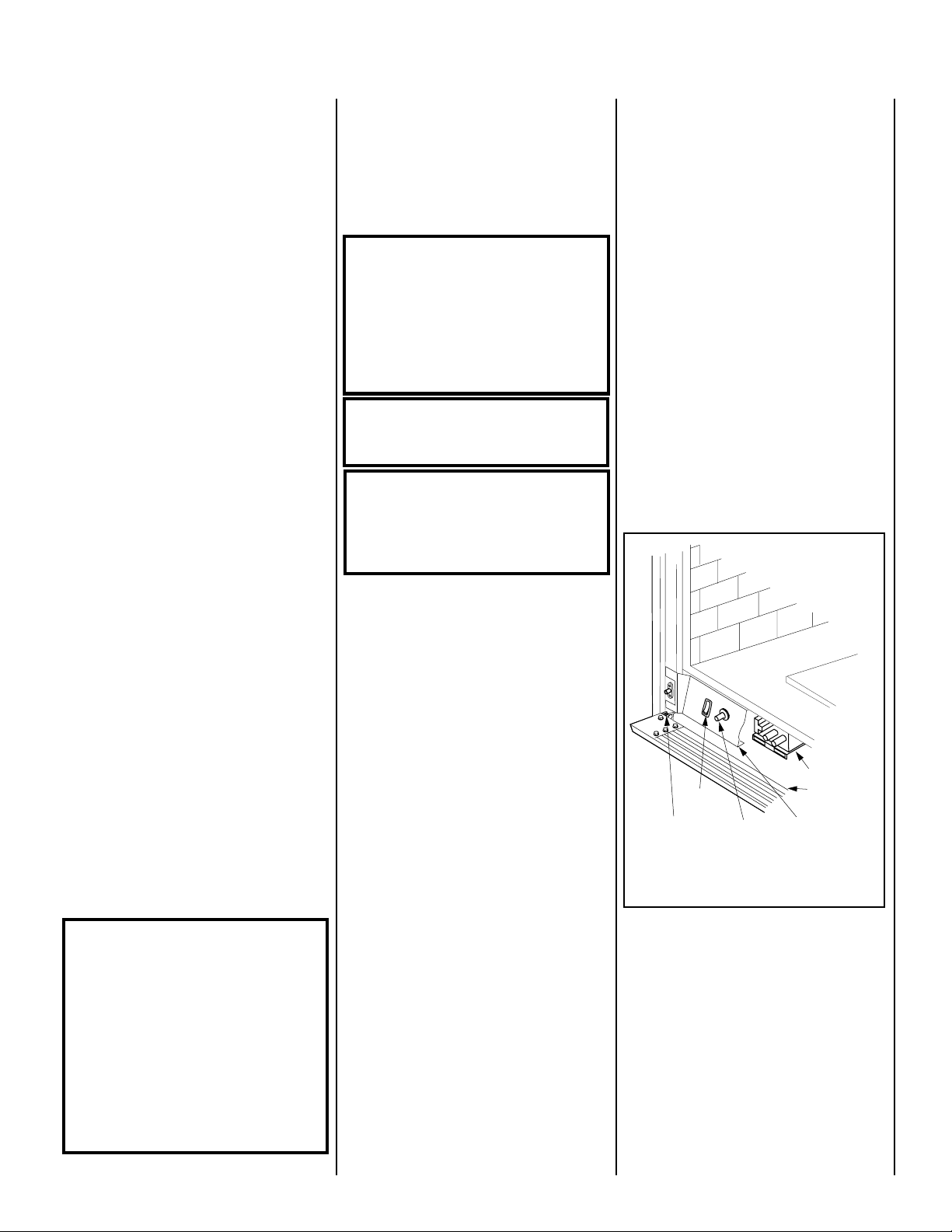
Piezo Ignitor
Gas Valve
Modesty Panel
Drop-down
Lower Door
ON/OFF
Switch
Hinge Pin
been under water. Immediately call a qualified,
professional service technician to inspect the
appliance and to replace any parts of the control system and any gas control which have
been under water.
Ne pas se servir de cet appareil s'il a été plongé
dans l'eau, complètement ou en partie. Appeler
un technicien qualifié pour inspecter l'appareil et
remplacer toute partie du système de contrôle et
toute commande qui ont été plongés dans l'leau.
Test gage connections are provided on the
front of the millivolt gas control valve (identified OUT for the manifold side and IN for inlet
pressure. A ¹⁄₈" NPT test gage connection is
provided on the electronic gas control valve
adjacent to the outlet to the main burner.
Minimum inlet gas pressure to these appliances
is 5.0 inches water column (1.24 kPa) for natural
gas and 11 inches water column (2.74 kPa) for
propane for the purpose of input adjustment.
Maximum inlet gas supply pressure to these appliances is 10.5 inches water column (2.61 kPa) for
natural gas and 13.0 inches water column (3.23 kPa)
for propane.
The appliance must be isolated from the gas
supply piping system (by closing its individual
manual shut-off valve) during any pressure testing of the gas supply piping system at test
pressures equal to or less than ¹⁄₂ psig (3.5 kPa).
The appliance and its individual shut-off valve must
be disconnected from the gas supply piping system
during any pressure testing of that system at pressures in excess of ¹⁄₂ psig (3.5 kPa).
These appliances must not be connected to a
chimney or flue serving a separate solid fuel
burning appliance.
Any safety guard or screen removed for servicing the appliance must be replaced prior to
operating the appliance.
WARNING: FAILURE TO COMPLY WITH
THE INSTALLATION AND OPERATING INSTRUCTIONS PROVIDED IN THIS DOCUMENT WILL RESULT IN AN IMPROPERLY INSTALLED AND OPERATING APPLIANCE, VOIDING ITS WARRANTY. ANY
CHANGE TO THIS APPLIANCE AND/OR
ITS OPERATING CONTROLS IS DANGEROUS. IMPROPER INSTALLATION OR USE
OF THIS APPLIANCE CAN CAUSE SERIOUS INJURY OR DEATH FROM FIRE,
BURNS, EXPLOSION OR CARBON MONOXIDE POISONING.
Carbon Monoxide Poisoning: Early signs of
carbon monoxide poisoning are similar to
the flu with headaches, dizziness and/or nausea. If you have these signs, obtain fresh air
immediately. Turn off the gas supply to the
appliance and have it serviced by a qualified
professional, as it may not be operating
correctly.
WARNING: CHILDREN AND ADULTS
SHOULD BE ALERTED TO THE HAZARDS
OF HIGH SURFACE TEMPERATURES. USE
CAUTION AROUND THE APPLIANCE TO
AVOID BURNS OR CLOTHING IGNITION.
YOUNG CHILDREN SHOULD BE CAREFULLY SUPERVISED WHEN THEY ARE IN
THE SAME ROOM AS THE APPLIANCE.
WARNING: DO NOT PLACE CLOTHING
OR OTHER FLAMMABLE MATERIALS
ON OR NEAR THIS APPLIANCE.
AVERTISSEMENT: SURVEILLER LES
ENFANTS. GARDER LES VÊTEMENTS,
LES MEUBLES, L'ESSENCE OU AUTRES
LIQUIDES À VAPEUR INFLAMMABLES
LOIN DE L'APPAREIL.
OPERATION AND CARE OF YOUR
APPLIANCE
Appliance operation may be controlled by the
following means: the factory provided modesty
panel-mounted ON-OFF control switch, a remotely located optional wall switch or optional
remote control.
The modesty panel mounted ON-OFF control
switch is located behind the hinged drop-down
panel below the appliance front glass enclosure
panel. See
Figure 1.
Gas Controls
The gas controls can be found behind the
hinged drop-down panel.
To open the hinged drop-down panel, actuate the
spring loaded, magnetic catches securing the
door, by gently depressing the outer top corners
of the door until the catches "pop" the door free,
allowing it to swing out and down to open.
On millivolt systems, the piezo ignitor, Hi/Lo
flame adjustment knob, and pilot and main gas
ON/OFF control knob are located on the modesty panel. On both millivolt and electronic
systems the gas valve is located behind the
modesty panel. See
Remove the bottom compartment door by
sliding the hinge pin, located at the door’s
left side, to the right until it disengages
from the left corner post hole. Pull the
door diagonally to the left, away from the
fireplace.
NOTE: DIAGRAMS & ILLUSTRATIONS NOT TO SCALE.
Figure 1.
Once the control compartment door has been
removed, the modesty panel can be removed
as follows: lift the modesty panel by the tab on
the panel’s right end, pull the right end of the
panel away from cabinet and then pull the
panel diagonally out of the corner post slots on
the left side of the unit. Remove the modesty
panel carefully, so that none of the wires
become loose or disconnected. Now complete
access to the gas control valve and its related
controls is attainable.
Operation of millivolt and electronic gas
control systems are different. Before lighting and operating your appliance determine
if you have a millivolt or electronic appli-
Refer to Figure 1
ance.
control valve. Millivolt appliances will be
fitted with the gas control valve shown in
Figure 2 on page 4
Appliances with electronic systems will be
fitted with the electronic valve shown in
3 on page 4
control valve that your appliance uses.
Figure 1
Millivolt Appliances -
To light millivolt appliances refer to the detailed
lighting instructions found on
and page 12
ing instructions may also be found on the pull
out lighting instruction labels attached to the
gas control valve.
Millivolt appliances are fitted with an ON/OFF
Rocker Switch for appliance ON/OFF control.
See
lighted, the ON/OFF rocker switch will control
the appliance ON/OFF operation. To operate:
Toggle the switch between its ON and OFF
positions.
. Familiarize yourself with the gas
Control Compartment Access Millivolt Control Valve Shown
(French). Millivolt appliance light-
Figure 1
for its location. Once the pilot is
for access to the gas
.
Figure
page 11 (English)
3
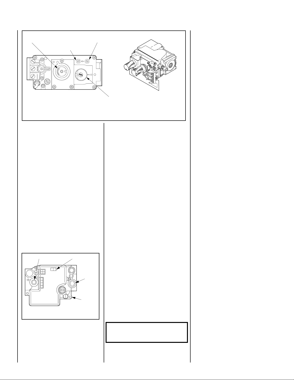
Variable Flame Height Adjustment
Manifold Pressure Port
TPTH TP TH
I
H
L
O
W
P
I
L
O
T
SIT Millivolt Gas Valve
Note: The piezo ignitor is located on the modesty panel - see Figure 1.
Figure 2
If your millivolt appliance is equipped with an
optional remote wall switch or remote control
kit and the pilot is lit, the appliance main burner
may be turned on and off with the wall switch or
remote control.
Electronic Appliances -
To light electronic appliances refer to the detailed lighting instructions found in both English and French on
pages 13 and 14
instructions respectively. Electronic appliance
lighting instructions may also be found on the
pull out lighting instruction labels attached to
the gas control valve.
Electronic appliances are fitted with an ON/OFF
Rocker Switch for appliance ON/OFF control.
See
Figure 1
for its location. Once the pilot is
lighted, the ON/OFF rocker switch will control
the appliance ON/OFF operation. To operate:
Toggle the switch between its ON and OFF
positions.
If your electronic appliance is equipped with an
optional remote wall switch or remote control
kit the appliance main burner may be turned on
and off with the wall switch or remote control.
Manifold Pressure Port
CONTROL
IG
N
IT
E
Figure 3
Honeywell Electronic
OFF
ON
Gas Valve
ON/OFF Switch
I
I
S
P
Variable Flame Height Adjustment
( Millivolt Appliances only)
1. All Millivolt appliances are equipped with a
variable gas control valve. Flame height for
these models may be adjusted through a range
between fixed low and high settings, alternately, while the appliance is in operation.
4
Inlet Pressure Port
IN
OUT
F
F
O
P
I
L
it
O
T
O
N
of these
Inlet
Pressure
Port
Electronic
Gas Control
Valve
Main Gas
Control Knob
Adjust the flame height as desired after lighting the appliance by rotating the variable
adjustment control knob located on the front
of the valve
(refer to Figure 2)
. (An extension
is provided to this knob so that the adjustment
may be made at the modesty panel.)
2. When lit for the first time, this appliance will
emit a slight odor for an hour or two. This is
due to the “burn-in” of internal paints and
lubricants used in the manufacturing process.
3. Keep lower control compartment clean by
vacuuming or brushing at least twice a year.
More frequent cleaning may be required due to
excessive lint from carpeting, bedding materials, etc. It is important that control compartments, burners and circulating air passageways of the appliance be kept clean.
4. Always turn off gas to the pilot (millivolt
appliances) before cleaning. Before re-lighting, refer to the lighting instructions in this
manual. Instructions are also found on a pullout panel located on the floor of the appliance.
5. Always keep the appliance area clear and
free from combustible materials, gasoline and
other flammable liquids.
6. Remember, Millivolt appliances have a continuous burning pilot flame. Exercise caution
when using products with combustible vapors.
7. Clean the front glass enclosure only when
necessary. Wipe surface with clean, dampened, soft cloth. Follow with dry, soft towel as
desired. Take care not to scratch the glass
surface.
WARNING: DO NOT USE ABRASIVE
CLEANERS. NEVER CLEAN THE GLASS
WHEN IT IS HOT.
NOTE: DIAGRAMS & ILLUSTRATIONS NOT TO SCALE.
CAUTION: DO NOT ATTEMPT TO TOUCH THE
FRONT ENCLOSURE GLASS WITH YOUR
HANDS WHILE THE FIREPLACE IS IN USE.
Maintenance
The appliance and venting system should be
thoroughly inspected before initial use and at
least annually by a qualified service technician. Proper maintenance and use will require
more frequent, less extensive inspections and
servicing by the homeowner.
Generally, annual inspections should be performed by a qualified service technician. More
frequent periodic inspections and cleanings
should be performed by the homeowner. Any
discrepancies discovered by the homeowner
should result in a call to a qualified service
technician to effect the repair or correction.
Refer to the maintenance schedule for maintenance tasks, procedures, periodicity and by
whom they should be performed. Always
verify proper operation of the appliance after
servicing.
IMPORTANT: TURN OFF GAS AND ANY ELECTRICAL POWER BEFORE SERVICING THE
APPLIANCE.
Control Compartment Access
The gas controls can be found behind the
hinged drop-down panel.
To open the door, actuate the spring loaded,
magnetic catches securing the door by gently
depressing the outer top corners of the door
until the catches "pop" the door free, allowing
it to swing out and down to open.
On millivolt systems, the piezo ignitor, Hi/Lo
flame adjustment knob, and pilot and main gas
ON/OFF control knob are located on the modesty panel. On both millivolt and electronic
systems the gas valve is located behind the
modesty panel. See
Remove the bottom compartment door by
sliding the hinge pin, located at the door’s
left side, to the right until it disengages
from the left corner post hole. Pull the
door diagonally to the left, away from the
fireplace.
Once the control compartment door has been
removed, the modesty panel can be removed
as follows: lift the modesty panel by the tab on
the panel’s right end, pull the right end of the
panel away from cabinet and then pull the
panel diagonally out of the corner post slots on
the left side of the unit. Remove the modesty
panel carefully, so that none of the wires
become loose or disconnected. Now complete
access to the gas control valve and its related
controls is attainable.
To ease door closure, depress the catches to
place them in their retracted position until they
stay there, then close the door.
Figure 1.
Maintenance Schedule
Annually (Before the onset of the Burning Season)
Maintenance Task Accomplishing Person Procedure
Inspecting/Cleaning Burner, Logs
and Controls
Check Flame Patterns and Flame Height
Inspecting/Cleaning Pilot and Burner
Checking Vent System
Appliance Checkout
Replacing Rockwool Ember Materials
Qualified Service Technician
Qualified Service Technician
Qualified Service Technician
Qualified Service Technician
Qualified Service Technician
Homeowner/Qualified Services Technician
Inspect valve and ensure it is properly operating. Check piping for leaks. Vacuum the
control compartment, fireplace logs and burner
area.
Figure 7 on page 7
Refer to
and verify the flame
pattern and height displayed by the appliance
conforms to the picture. Flames must not
impinge on the logs.
Refer to
Figure 8 (SIT) or Figure 9 (Honeywell)
on page 7
. Remove any surface build-up on pilot
and burner assembly. Wipe the pilot nozzles,
ignitor/flame rod and hood. Ensure the pilot
flame engulfs the flame sensor as shown.
Inspect the vent system at the top and at the
base (within the firebox) for signs of blockage
or obstruction. Look for any signs of dislocation of the vent components.
Perform the appropriate appliance checkout
procedure detailed in this manual.
Remove old ember materials and vacuum the
screened rockwool placement area. Place new
rockwool as described in this document.
Periodically (After the Burning Season)
Maintenance Task Accomplishing Person Procedure
Cleaning Firebox Interior
Check Flame Patterns and Flame Height
Checking Vent System
Cleaning Front Glass Enclosure Panel
Homeowner
Homeowner
Homeowner
Homeowner
Carefully remove logs, Rockwool and volcanic stone if used. Vacuum out interior of the
firebox. Clean firebox walls and log grate.
Replace logs, Rockwool and volcanic stone
as detailed in this manual.
Refer to Refer to
Figure 7 on page 7
and verify
the flame pattern and height displayed by the
appliance conforms to the picture. Flames
must not impinge on the logs.
Inspect the vent system at the top and at the
base (within the firebox) for signs of blockage or obstruction. Look for any signs of
dislocation of the vent components.
Clean as necessary following the directions
provided in this manual. DO NOT TOUCH OR
ATTEMPT TO CLEAN GLASS WHILE HOT.
NOTE: DIAGRAMS & ILLUSTRATIONS NOT TO SCALE.
5
Front Glass Enclosure Panel, Removal
and Installation.
WARNING: NEVER OPERATE THE APPLIANCE WITHOUT THE FRONT GLASS ENCLOSURE PANEL IN PLACE AND SECURE.
DO NOT OPERATE APPLIANCE WITH
FRONT GLASS CRACKED, BROKEN OR
MISSING. REPLACEMENT MUST BE
DONE BY A LICENSED OR QUALIFIED
SERVICE TECHNICIAN.
These are direct-vent appliances. They are
designed to operate only when the front glass
enclosure panel is installed. Generally the front
glass enclosure panel should not be removed
except to gain access to the components within
the firebox, and the appliance may only be
operated without the front glass enclosure panel
in place for very brief periods of time during
appliance checkout and adjustment. Be sure
that the flame appearance will be diminished
while the front glass enclosure panel is removed.
WARNING: HANDLE THIS GLASS WITH
EXTREME CARE! TEMPERED GLASS IS
SUSCEPTIBLE TO DAMAGE – DO NOT
SCRATCH OR HANDLE ROUGHLY WHILE
REINSTALLING THE GLASS DOOR
FRAME.
WARNING: NO NOT ATTEMPT TO SUBSTITUTE THE MATERIALS USED ON THIS
DOOR, OR REPLACE CRACKED OR BROKEN GLASS WITH ANY MATERIALS
OTHER THAN THOSE PROVIDED BY THE
APPLIANCE MANUFACTURER.
THE GLASS DOOR OF THIS APPLIANCE MUST
ONLY BE REPLACED AS A COMPLETE UNIT AS
PROVIDED BY THE MANUFACTURER. DO
NOT ATTEMPT TO REPLACE BROKEN,
CRACKED OR CHIPPED GLASS SEPARATELY.
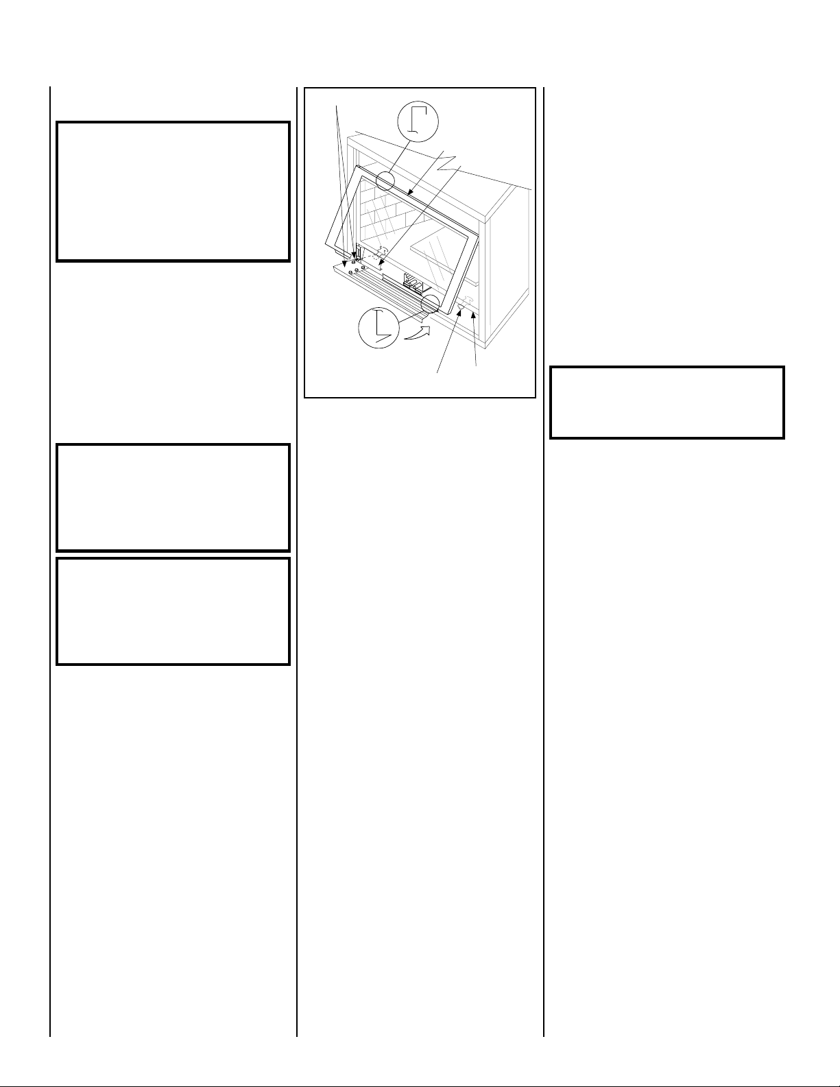
Refer to
enclosure panel as follows:
1. Open the hinged drop-down control com-
partment panel.
2. Remove the bottom compartment door
by sliding the hinge pin, located at the
door’s left side, to the right until it disengages from the left corner post hole. Pull
the door diagonally to the left, away from
the fireplace.
3. Remove the modesty panel as follows: lift the
modesty panel by the tab on the panel’s right end,
pull the right end of the panel away from cabinet
and then pull the panel diagonally out of the
corner post slots on the left side of the unit.
Remove the modesty panel carefully, so that
none of the wires become loose or disconnected.
6
Figure 4
and remove the front glass
Lower Compartment Door and Hinge
Top Flange
Glass Door Frame
Glass Door
Modesty Panel
Bottom Vee-flange
Glass Door Frame
Figure 4
4. Locate the two (2) latches at the top of the
control compartment and disengage them from
the floor frame bottom Vee-flange, pulling
down on their handles to open them.
5. Swing the bottom of the door out and raise
it slightly to lift the top flange of the door frame
away from the appliance.
To install the front glass enclosure panel,
proceed as follows:
1. Retrieve the glass door frame. Visually
inspect the gasket on the backside of the panel.
The gasket surface must be clean, free of
irregularities and seated firmly.
2. Position the door frame in front of the
firebox opening and engage the top flange over
the lip at the top of the firebox opening.
3. Swing the door down and back. Ensure the
gasket seats evenly as the door draws shut.
Engage the Vee-flange at the bottom of the
door with the latches and close the latches to
secure the door.
4. Reinstall the modesty panel by inserting the
left end of it into the left corner post slots,
swing the right end toward the right corner
post and hook it in the right corner post slot.
5. Reinstall the bottom compartment door by
inserting the right side locating pin into the right
cabinet corner post and then the left side springloaded pin into the left cabinet corner post.
Glass Door Latch
Firebox Floor
Burner Adjustments
The following paragraphs address burner adjustment concerns and procedures.
Flame Appearance and Sooting
Proper flame appearance is a matter of taste.
Generally most people prefer the warm glow of
a yellow to orange flame. Appliances operated
with air shutter openings that are too large will
exhibit flames that are blue and transparent.
These weak, blue and transparent flames are
termed anemic. If the air shutter opening is too
small sooting may develop.
NOTE: DIAGRAMS & ILLUSTRATIONS NOT TO SCALE.
Sooting is indicated by black puffs developing
at the tips of very long orange flames. Sooting
results in black deposits forming on the logs,
appliance inside surfaces and on exterior surfaces adjacent to the vent termination.
Sooting is caused by incomplete combustion in
the flames and a lack of combustion air entering
the air shutter opening. To achieve a warm
yellow to orange flame with an orange body that
does not soot, the shutter opening must be
adjusted between these two extremes. No smoke
or soot should be present. Reposition the logs if
the flames impinge on any of them.
If the logs are properly positioned and sooting
conditions exist, the air shutter opening on the
main burner tube should be adjusted. Normally,
the more offsets in the vent system, the greater
the need for the air shutter to be opened further.
WARNING: AIR SHUTTER ADJUSTMENT
SHOULD ONLY BE PERFORMED BY A
QUALIFIED PROFESSIONAL SERVICE
TECHNICIAN.
ENSURE THAT THE FRONT GLASS PANEL IS IN
PLACE AND SEALED DURING ADJUSTMENT.
Adjustment
CAUTION: THE ADJUSTMENT ROD AND
NEARBY APPLIANCE SURFACES ARE HOT.
EXERCISE CAUTION TO AVOID INJURY WHILE
ADJUSTING FLAME APPEARANCE.
To adjust the flame, move the adjustment rod
(located in the lower control area) back or
forward to increase or reduce the air shutter
opening, respectively. Position the air shutter
to the factory setting as shown in
page 7
. Allow the burner to operate for at least
15 minutes. Observe the flame continuously. If
it appears weak or sooty as previously described, adjust the air shutter by pushing or
pulling on the adjustment rod until the flame
appearance is as desired.
The adjustment rod and associated adjustable
air shutter is patented technology. Flame adjustments can be made quickly and accurately
to taste without the need of disassembling the
appliance and waiting for 30 minutes after each
adjustment.
Propane models may exhibit a flame pattern
that may candle or appear stringy. If this is
problematic or persists as the appliance is
continually operated, adjust the air shutter closed
as described in the previous paragraphs. Operate the appliance for a period of time as the
effect diminishes, ensuring that the appliance
does not develop sooty flames.
When satisfied that the appliance operates properly, proceed to finish the installation. Leave the
control knob in “ON” position and turn the
remote switch “OFF.” Close the lower control
compartment door.
Figure 5 on
 Loading...